CN106576350B - Channel selection scanning in shared spectrum - Google Patents
Channel selection scanning in shared spectrum Download PDFInfo
- Publication number
- CN106576350B CN106576350B CN201580019935.7A CN201580019935A CN106576350B CN 106576350 B CN106576350 B CN 106576350B CN 201580019935 A CN201580019935 A CN 201580019935A CN 106576350 B CN106576350 B CN 106576350B
- Authority
- CN
- China
- Prior art keywords
- channel
- rat
- access
- access point
- operating channel
- Prior art date
- Legal status (The legal status is an assumption and is not a legal conclusion. Google has not performed a legal analysis and makes no representation as to the accuracy of the status listed.)
- Active
Links
- 238000001228 spectrum Methods 0.000 title abstract description 9
- 238000004891 communication Methods 0.000 claims abstract description 126
- 238000000034 method Methods 0.000 claims abstract description 41
- 238000013442 quality metrics Methods 0.000 claims abstract description 39
- 230000004044 response Effects 0.000 claims abstract description 28
- 238000005259 measurement Methods 0.000 claims description 89
- 238000005516 engineering process Methods 0.000 claims description 29
- 230000011664 signaling Effects 0.000 claims description 25
- 230000007774 longterm Effects 0.000 claims description 4
- 230000006870 function Effects 0.000 abstract description 35
- 238000013461 design Methods 0.000 description 17
- 230000005540 biological transmission Effects 0.000 description 15
- 238000010586 diagram Methods 0.000 description 12
- 238000007781 pre-processing Methods 0.000 description 8
- 230000001960 triggered effect Effects 0.000 description 7
- 230000008901 benefit Effects 0.000 description 5
- 230000009471 action Effects 0.000 description 4
- 230000004913 activation Effects 0.000 description 4
- 230000009849 deactivation Effects 0.000 description 4
- 230000003044 adaptive effect Effects 0.000 description 3
- 238000012545 processing Methods 0.000 description 3
- 230000004931 aggregating effect Effects 0.000 description 2
- 239000002245 particle Substances 0.000 description 2
- 239000013589 supplement Substances 0.000 description 2
- 230000002776 aggregation Effects 0.000 description 1
- 238000004220 aggregation Methods 0.000 description 1
- 239000000969 carrier Substances 0.000 description 1
- 230000001413 cellular effect Effects 0.000 description 1
- 230000005754 cellular signaling Effects 0.000 description 1
- 230000001351 cycling effect Effects 0.000 description 1
- 238000012986 modification Methods 0.000 description 1
- 230000004048 modification Effects 0.000 description 1
- 238000012544 monitoring process Methods 0.000 description 1
- 230000003287 optical effect Effects 0.000 description 1
- 230000000737 periodic effect Effects 0.000 description 1
- 230000009467 reduction Effects 0.000 description 1
- 230000008054 signal transmission Effects 0.000 description 1
- 238000000638 solvent extraction Methods 0.000 description 1
- 230000003595 spectral effect Effects 0.000 description 1
- 230000000153 supplemental effect Effects 0.000 description 1
Images


Classifications
-
- H—ELECTRICITY
- H04—ELECTRIC COMMUNICATION TECHNIQUE
- H04W—WIRELESS COMMUNICATION NETWORKS
- H04W16/00—Network planning, e.g. coverage or traffic planning tools; Network deployment, e.g. resource partitioning or cells structures
- H04W16/14—Spectrum sharing arrangements between different networks
-
- H—ELECTRICITY
- H04—ELECTRIC COMMUNICATION TECHNIQUE
- H04J—MULTIPLEX COMMUNICATION
- H04J3/00—Time-division multiplex systems
- H04J3/16—Time-division multiplex systems in which the time allocation to individual channels within a transmission cycle is variable, e.g. to accommodate varying complexity of signals, to vary number of channels transmitted
- H04J3/1694—Allocation of channels in TDM/TDMA networks, e.g. distributed multiplexers
-
- H—ELECTRICITY
- H04—ELECTRIC COMMUNICATION TECHNIQUE
- H04W—WIRELESS COMMUNICATION NETWORKS
- H04W24/00—Supervisory, monitoring or testing arrangements
- H04W24/08—Testing, supervising or monitoring using real traffic
-
- H—ELECTRICITY
- H04—ELECTRIC COMMUNICATION TECHNIQUE
- H04W—WIRELESS COMMUNICATION NETWORKS
- H04W72/00—Local resource management
- H04W72/04—Wireless resource allocation
- H04W72/044—Wireless resource allocation based on the type of the allocated resource
- H04W72/0453—Resources in frequency domain, e.g. a carrier in FDMA
-
- H—ELECTRICITY
- H04—ELECTRIC COMMUNICATION TECHNIQUE
- H04W—WIRELESS COMMUNICATION NETWORKS
- H04W72/00—Local resource management
- H04W72/50—Allocation or scheduling criteria for wireless resources
- H04W72/54—Allocation or scheduling criteria for wireless resources based on quality criteria
-
- H—ELECTRICITY
- H04—ELECTRIC COMMUNICATION TECHNIQUE
- H04W—WIRELESS COMMUNICATION NETWORKS
- H04W72/00—Local resource management
- H04W72/50—Allocation or scheduling criteria for wireless resources
- H04W72/54—Allocation or scheduling criteria for wireless resources based on quality criteria
- H04W72/541—Allocation or scheduling criteria for wireless resources based on quality criteria using the level of interference
-
- H—ELECTRICITY
- H04—ELECTRIC COMMUNICATION TECHNIQUE
- H04W—WIRELESS COMMUNICATION NETWORKS
- H04W72/00—Local resource management
- H04W72/50—Allocation or scheduling criteria for wireless resources
- H04W72/54—Allocation or scheduling criteria for wireless resources based on quality criteria
- H04W72/542—Allocation or scheduling criteria for wireless resources based on quality criteria using measured or perceived quality
-
- H—ELECTRICITY
- H04—ELECTRIC COMMUNICATION TECHNIQUE
- H04W—WIRELESS COMMUNICATION NETWORKS
- H04W74/00—Wireless channel access
- H04W74/08—Non-scheduled access, e.g. ALOHA
- H04W74/0808—Non-scheduled access, e.g. ALOHA using carrier sensing, e.g. carrier sense multiple access [CSMA]
-
- H—ELECTRICITY
- H04—ELECTRIC COMMUNICATION TECHNIQUE
- H04W—WIRELESS COMMUNICATION NETWORKS
- H04W88/00—Devices specially adapted for wireless communication networks, e.g. terminals, base stations or access point devices
- H04W88/08—Access point devices
- H04W88/10—Access point devices adapted for operation in multiple networks, e.g. multi-mode access points
-
- H—ELECTRICITY
- H04—ELECTRIC COMMUNICATION TECHNIQUE
- H04W—WIRELESS COMMUNICATION NETWORKS
- H04W84/00—Network topologies
- H04W84/02—Hierarchically pre-organised networks, e.g. paging networks, cellular networks, WLAN [Wireless Local Area Network] or WLL [Wireless Local Loop]
- H04W84/04—Large scale networks; Deep hierarchical networks
- H04W84/042—Public Land Mobile systems, e.g. cellular systems
- H04W84/045—Public Land Mobile systems, e.g. cellular systems using private Base Stations, e.g. femto Base Stations, home Node B
Landscapes
- Engineering & Computer Science (AREA)
- Computer Networks & Wireless Communication (AREA)
- Signal Processing (AREA)
- Quality & Reliability (AREA)
- Mobile Radio Communication Systems (AREA)
- Time-Division Multiplex Systems (AREA)
Abstract
Techniques for channel selection and related operations in a shared spectrum environment are disclosed. In one example, a channel selector or the like may be used to select one of the plurality of available channels as the operating channel based on a comparison of cost functions for each of the available channels, where the cost functions are based on separate utility and penalty metrics. In another example, a channel scanner or the like can be employed to trigger a channel scan in response to a channel quality metric indicating poor service for a threshold number or proportion of access terminals. In another example, the operating mode controller may be to trigger a Time Division Multiplexing (TDM) mode on the operating channel in response to the utilization metric being above a threshold. The TDM pattern may cycle between activated periods and deactivated periods according to a TDM communication pattern.
Description
Cross Reference to Related Applications
This patent application has priority TO U.S. provisional application No.61/981,564 entitled "CHANNEL SELECTION for preliminary PRE-PROCESSING IN unlicenced speed" filed on 18.2014 and U.S. provisional application No.62/013,412 entitled "CHANNEL SELECTION TO temporary inter-PROCESSING A WIRELESS LOCAL AREA NETWORK FROM a cell NETWORK", filed on 17.6.2014, each of which is assigned TO the assignee of the present application and is hereby expressly incorporated herein by reference IN its entirety.
Citation of pending patent application
This patent application is also related to the following pending U.S. patent applications: U.S. patent application Ser. No.144315U 1, "CHANNEL SELECTION METRICS IN SHARED SPECTRUM," and U.S. patent application Ser. No.144315U3, "CHANNEL SELECTION CO-EXISTENCE IN SHORED SPECTRUM," each of which is filed concurrently with the present patent application and each of which is assigned to the assignee of the present application and is hereby expressly incorporated herein by reference IN its entirety.
Technical Field
Aspects of the present disclosure relate generally to telecommunications, and more particularly to coexistence between wireless Radio Access Technologies (RATs), and the like.
Background
Wireless communication systems are widely deployed to provide various types of communication content such as voice, data, multimedia, and so on. A typical wireless communication system is a multiple-access system capable of supporting communication with multiple users by sharing available system resources (e.g., bandwidth, transmit power, etc.). Examples of such multiple-access systems may include Code Division Multiple Access (CDMA) systems, Time Division Multiple Access (TDMA) systems, Frequency Division Multiple Access (FDMA) systems, Orthogonal Frequency Division Multiple Access (OFDMA) systems, and others. These systems are typically deployed in compliance with specifications such as Long Term Evolution (LTE) provided by the third generation partnership project (3GPP), Ultra Mobile Broadband (UMB) and evolution data optimized (EV-DO) provided by the third generation partnership project 2(3GPP2), 802.11 provided by the Institute of Electrical and Electronics Engineers (IEEE), and so on.
In cellular networks, a "macrocell" access point provides connection and coverage to a large number of users over a particular geographic area. Macro network deployments are carefully planned, designed and implemented to provide good coverage over the geographic area. To improve indoor or other specific geographic coverage (such as for residential homes and office buildings), additional "small cells" (typically low power access points) have recently begun to be deployed to supplement conventional macro networks. Small cell access points may also provide incremental capacity growth, richer user experience, and the like.
Recently, small cell LTE operation has been extended, for example, into unlicensed frequency bands, such as the unlicensed national information infrastructure (U-NII) band used by Wireless Local Area Network (WLAN) technologies. This extension of small cell LTE operation is designed to improve spectral efficiency and thus increase the capacity of LTE systems. However, it is also possible to encroach on the operation of other Radio Access Technologies (RATs) that typically utilize the same unlicensed frequency band, most notably the ieee802.11x WLAN technology commonly referred to as "Wi-Fi".
Disclosure of Invention
Techniques for channel selection and related operations in a shared spectrum environment are disclosed.
In one example, an access point apparatus for managing an operating channel of a first Radio Access Technology (RAT) over a communication medium shared with a second RAT is disclosed. The access point device may include, for example, one or more transceivers, a penalty metric generator, a utility metric generator, a cost function generator, and a channel selector. The one or more transceivers may be configured to perform, at an access point, a scan of available channels and receive channel measurement reports for the available channels from an access terminal. The penalty metric generator may be configured to determine a penalty metric for each of the available channels based on a channel scan. The utility metric generator may be configured to determine a utility metric for each of the available channels based on the channel measurement reports. The cost function generator may be configured to calculate a cost function for each of the available channels based on the respective penalty metrics and the respective utility metrics. The channel selector may be configured to select one of the available channels as the operating channel based on a comparison of a cost function for each of the available channels.
In another example, a method for managing an operating channel of a first Radio Access Technology (RAT) over a communication medium shared with a second RAT is disclosed. The method may for example comprise: performing a scan of available channels at an access point; receiving a channel measurement report for the available channels from an access terminal; determining a penalty metric for each of the available channels based on a channel scan; determining a utility metric for each of the available channels based on the channel measurement reports; calculating a cost function for each of the available channels based on the respective penalty metrics and the respective utility metrics; and selecting one of the available channels as the operating channel based on a comparison of the cost functions for each of the available channels.
In another example, another apparatus for managing an operating channel of a first Radio Access Technology (RAT) over a communication medium shared with a second RAT is disclosed. The apparatus may for example comprise: means for performing a scan of available channels at an access point; means for receiving a channel measurement report for the available channels from an access terminal; means for determining a penalty metric for each of the available channels based on a channel scan; means for determining a utility metric for each of the available channels based on the channel measurement reports; means for calculating a cost function for each of the available channels based on the respective penalty metrics and the respective utility metrics; and means for selecting one of the available channels as the operating channel based on a comparison of the cost functions for each of the available channels.
In another example, a computer-readable medium is disclosed that includes code, which, when executed by a processor, causes the processor to perform operations for managing an operating channel of a first RAT over a communication medium shared with a second RAT. The computer-readable medium may include, for example: code for performing a scan of available channels at an access point; code for receiving a channel measurement report for the available channels from an access terminal; code for determining a penalty metric for each of the available channels based on a channel scan; code for determining a utility metric for each of the available channels based on the channel measurement reports; code for calculating a cost function for each of the available channels based on the respective penalty metrics and the respective utility metrics; and code for selecting one of the available channels as the operating channel based on a comparison of the cost functions for each of the available channels.
In another example, another access point apparatus for managing an operating channel of a first RAT over a communication medium shared with a second RAT is disclosed. The access point device may, for example, comprise: a transceiver, a channel quality analyzer, a channel scanner, and a channel selector. The transceiver may be configured to receive one or more channel measurement reports for a current operating channel of the first RAT from each of a plurality of access terminals. The channel quality analyzer may be configured to determine a channel quality metric for the current operating channel based on the channel measurement report. The channel scanner may be configured to: triggering a channel scan in response to the channel quality metric indicating poor service for a threshold number or proportion of access terminals. The channel selector may be configured to select a new operating channel based on the channel scan.
In another example, another method for managing an operating channel of a first RAT over a communication medium shared with a second RAT is disclosed. The method may for example comprise: receiving one or more channel measurement reports for a current operating channel of the first RAT from each of a plurality of access terminals; determining a channel quality metric for the current operating channel based on the channel measurement report; triggering a channel scan in response to the channel quality metric indicating poor service for a threshold number or proportion of access terminals; and selecting a new operating channel based on the channel scan.
In another example, another apparatus for managing an operating channel of a first RAT over a communication medium shared with a second RAT is disclosed. The apparatus may for example comprise: means for receiving one or more channel measurement reports for a current operating channel of the first RAT from each of a plurality of access terminals; means for determining a channel quality metric for the current operating channel based on the channel measurement report; means for triggering a channel scan in response to the channel quality metric indicating poor service for a threshold number or proportion of access terminals; and means for selecting a new operating channel based on the channel scan.
In another example, another computer-readable medium is disclosed that includes code, which, when executed by a processor, causes the processor to perform operations for managing an operating channel of a first RAT over a communication medium shared with a second RAT. The computer-readable medium may include, for example: code for receiving one or more channel measurement reports for a current operating channel of the first RAT from each of a plurality of access terminals; code for determining a channel quality metric for the current operating channel based on the channel measurement report; code for triggering a channel scan in response to the channel quality metric indicating poor service for a threshold number or proportion of access terminals; and code for selecting a new operating channel based on the channel scan.
In another example, another access point apparatus for managing an operating channel of a first RAT over a communication medium shared with a second RAT is disclosed. The access point device may include, for example, one or more transceivers, a channel selector, an interference analyzer, and an operation mode controller. The one or more transceivers may be configured to perform a scan of available channels at the access point. The channel selector may be configured to select one of the available channels as an operating channel of the first RAT based on a channel scan. The analysis jammer may be configured to determine a utilization metric for the operating channel. The operation mode controller may be configured to: triggering a Time Division Multiplexing (TDM) pattern on the operating channel in response to the utilization metric being above a threshold, wherein the TDM pattern cycles operation between activated and deactivated periods of communication in accordance with a TDM communication pattern.
In another example, another method for managing an operating channel of a first RAT over a communication medium shared with a second RAT is disclosed. The method may for example comprise: performing a scan of available channels at an access point; selecting one of the available channels as an operating channel of the first RAT based on a channel scan; determining a utilization metric for the operating channel; and in response to the utilization metric being above a threshold, triggering a TDM pattern on the operating channel, wherein the TDM pattern cycles operation between activated and deactivated periods of communication in accordance with a TDM communication pattern.
In another example, another apparatus for managing an operating channel of a first RAT over a communication medium shared with a second RAT is disclosed. The apparatus may for example comprise: means for performing a scan of available channels at an access point; means for selecting one of the available channels as an operating channel of the first RAT based on a channel scan; means for determining a utilization metric for the operating channel; and means for triggering a TDM pattern on the operating channel in response to the utilization metric being above a threshold, wherein the TDM pattern cycles operation between activated and deactivated periods of communication in accordance with a TDM communication pattern.
In another example, another computer-readable medium is disclosed that includes code, which, when executed by a processor, causes the processor to perform operations for managing an operating channel of a first RAT over a communication medium shared with a second RAT. The computer-readable medium may include, for example: code for performing a scan of available channels at an access point; code for selecting one of the available channels as an operating channel of the first RAT based on a channel scan; code for determining a utilization metric for the operating channel; and code for triggering a TDM pattern on the operating channel in response to the utilization metric being above a threshold, wherein the TDM pattern cycles operation between activated and deactivated periods of communication in accordance with a TDM communication pattern.
Drawings
The accompanying drawings are presented to aid in the description of various aspects of the disclosure and are provided solely for illustration of the aspects and not limitation thereof.
Fig. 1 illustrates an example wireless communication system that includes a small cell Access Point (AP) in communication with an Access Terminal (AT).
Fig. 2 is a block diagram illustrating certain example aspects of a channel selection controller in greater detail.
Fig. 3 is a block diagram illustrating certain example aspects of a channel scan controller in greater detail.
FIG. 4 is a block diagram illustrating certain example aspects of a coexist controller in greater detail.
Fig. 5 illustrates certain aspects of an example Time Division Multiplexing (TDM) communication scheme, referred to herein as Carrier Sense Adaptive Transmission (CSAT), that may be used to implement a TDM mode of operation.
Fig. 6 is a flow diagram illustrating an example method of managing an operating channel of a first Radio Access Technology (RAT) over a communication medium shared with a second RAT, according to techniques herein.
Fig. 7 is a flow diagram illustrating another example method for managing an operating channel of a first RAT over a communication medium shared with a second RAT in accordance with the techniques herein.
Fig. 8 is a flow diagram illustrating another example method for managing an operating channel of a first RAT over a communication medium shared with a second RAT in accordance with the techniques herein.
Fig. 9-11 provide alternative illustrations of an apparatus for implementing an access point and/or an access terminal represented as a series of interrelated functional modules.
Detailed Description
The present disclosure relates generally to channel selection and related operations in a shared spectrum environment. According to certain aspects, one of the plurality of available channels may be selected as the operating channel based on a comparison of a cost function for each of the available channels, wherein the cost function is based on separate utility and penalty metrics. According to other aspects, a channel scan for a new operating channel may be triggered in response to a channel quality metric indicating poor service for a threshold number or proportion of access terminals. According to other aspects, a Time Division Multiplexing (TDM) mode may be triggered on an operating channel in response to a utilization metric being above a threshold. An example TDM communication scheme, referred to herein as Carrier Sense Adaptive Transmission (CSAT), may be used to define a series of activated and deactivated operating periods over a given communication medium.
More particular aspects of the disclosure are provided in the following description and related drawings directed to various examples provided for purposes of illustration. Alternative aspects may be devised without departing from the scope of the disclosure. Additionally, well-known aspects of the disclosure may not be described in detail or may be omitted so as not to obscure the more relevant details.
Those of skill in the art would understand that the information and signals described below may be represented using any of a variety of different technologies and techniques. For example, data, instructions, commands, information, signals, bits, symbols, and chips that may be referenced throughout the following description may be represented by voltages, currents, electromagnetic waves, magnetic fields or particles, optical fields or particles, or any combination thereof, depending in part on the particular application, desired design, corresponding technology, and so forth.
Further, many aspects are described in terms of sequences of actions to be performed by, for example, elements of a computing device. It will be recognized that various actions described herein can be performed by specific circuits (e.g., Application Specific Integrated Circuits (ASICs)), by program instructions being executed by one or more processors, or by a combination of both. Further, for each of the aspects described herein, the corresponding form of any such aspect may be implemented, for example, as a "logic configured to perform the described action.
Fig. 1 illustrates an example wireless communication system that includes a small cell Access Point (AP) in communication with an Access Terminal (AT). Unless otherwise specified, the terms "access terminal" and "access point" are not intended to be specific or limited to any particular Radio Access Technology (RAT). In general, an access terminal may be any wireless communication device (e.g., a mobile phone, router, personal computer, server, entertainment device, internet of things (IOT)/internet of everything (IOE)) capable device, in-vehicle communication device, etc.) that allows a user to communicate over a communication network, and may alternatively be referred to as a user equipment (UD), a Mobile Station (MS), a user Station (STA), a User Equipment (UE), etc. in different RAT environments. Similarly, an access point may operate in accordance with one or more RATs when communicating with access terminals depending on the network in which the access point is deployed and may alternatively be referred to as a Base Station (BS), network node, node B, evolved node B (enb), etc. A "small cell" generally refers to a type of low power access point that may include or otherwise be referred to as a femtocell, picocell, microcell, Wi-Fi AP, other small coverage area AP. Small cells may be deployed to supplement macro cell coverage, which may cover several square miles in a neighborhood or rural environment, enabling improved signal transmission, incremental capacity growth, richer user experience, and the like.
In the example of fig. 1, access point 110 and access terminal 120 each typically include a wireless communication device (represented by communication devices 112 and 122) for communicating with other network nodes via at least one specified RAT. The communication devices 112 and 122 may be configured differently for: signals (e.g., messages, indications, information, etc.) are transmitted and encoded, and conversely, signals (e.g., messages, indications, information, pilots, etc.) are received and decoded, in accordance with the specified RAT. Access point 110 and access terminal 120 may also each generally include a communication controller (represented by communication controllers 114 and 124) for controlling (e.g., directing, modifying, enabling, disabling, etc.) operation of their respective communication devices 112 and 122. The communication controllers 114 and 124 may operate under the direction of or otherwise in conjunction with respective host system functions (shown as processing systems 116 and 126 and memory components 118 and 128). In some designs, communication controllers 114 and 124 may be partially or wholly attributed to respective host system functions.
Turning in more detail to the illustrated communications, the access terminal 120 can send and receive messages with the access point 110 via the wireless link 130 that include information related to various types of communications (e.g., voice, data, multimedia services, associated control signaling, etc.). The wireless link 130 may operate over a communication channel of interest, shown for example in fig. 1 as medium 132, which may be shared with other communications as well as other RATs. This type of medium may be comprised of one or more frequency, time, and/or spatial communication resources (e.g., including one or more channels across one or more carriers) associated with communication between one or more transmitter/receiver pairs, such as access point 110 and access terminal 120 for medium 132.
As a particular example, the medium 132 may correspond to at least a portion of an unlicensed frequency band shared with other RATs. In general, the access point 110 and the access terminal 120 may operate according to one or more RATs via the wireless link 130 depending on the network in which they are deployed. These networks may include, for example, different variations of Code Division Multiple Access (CDMA) networks, Time Division Multiple Access (TDMA) networks, Frequency Division Multiple Access (FDMA) networks, orthogonal FDMA (ofdma) networks, single carrier FDMA (SC-FDMA) networks, and the like. While different licensed frequency bands have been reserved for such communications (e.g., by government entities such as the Federal Communications Commission (FCC) in the united states), certain communication networks, particularly those employing small cell access points as in the system of fig. 1, have extended operation to unlicensed frequency bands such as the unlicensed national information infrastructure (U-NII) frequency bands used by Wireless Local Area Network (WLAN) technology (most notably the IEEE802.11x WLAN technology commonly referred to as "Wi-Fi").
In the example of fig. 1, the communication device 112 of the access point 110 includes two co-located transceivers operating according to respective RATs, including a "RAT a" transceiver 140 and a "RAT B" transceiver 142. As used herein, a "transceiver" may include a transmitter circuit, a receiver circuit, or a combination thereof, but need not provide both transmit and receive functionality in all designs. For example, when it is not necessary to provide full communication, low functionality receiver circuitry may be employed in some designs to reduce cost (e.g., a Wi-Fi chip or similar circuitry that provides only low level sniffing). Further, as used herein, the term "co-located" (e.g., radio, access point, transceiver, etc.) may refer to one of various arrangements. For example, components in the same housing; components hosted by the same processor; components within a specified distance of each other; and/or components connected via an interface (e.g., an ethernet switch), where the interface meets the latency requirements of any required inter-component communication (e.g., messaging).
The RAT a transceiver 140 and the RAT B transceiver 142 may provide different functions and may be used for different purposes. By way of example, the RAT a transceiver 140 may operate in accordance with Long Term Evolution (LTE) technology to provide communications with the access terminal 120 over the wireless link 130, while the RAT B transceiver 142 operates in accordance with Wi-Fi technology to monitor for Wi-Fi signaling on the medium 132 that may interfere with or may be interfered with by LTE communications. As desired, in some designs, the communication device 122 of the access terminal 120 may include similar RAT a transceiver functionality and/or RAT B transceiver functionality.
As discussed in more detail below with reference to fig. 2-5, the communication controller 114 of the access point 110 may include, in various aspects, a channel selection controller 144, a channel scanning controller 146, and/or a coexistence controller 148, which may operate in conjunction with the RAT a transceiver 140 and the RAT B transceiver 142 to manage operations on the medium 132. As will be apparent from the discussion below, in different designs, one or more of these components may be omitted when their respective functions are not desired. It is not necessary that channel selection controller 144, channel scan controller 146, and coexistence controller 148 be deployed in conjunction with one another.
Fig. 2 is a block diagram illustrating certain example aspects of the channel selection controller 144 of fig. 1 in greater detail. As shown, channel selection controller 144 may include a penalty metric generator 202, a utility metric generator 204, a cost function generator 206, and a channel selector 208.
To assess the feasibility of various channels available for use on the medium 132 for communication over the wireless link 130, the communication device 112, via the RAT a transceiver 140 and/or the RAT B transceiver 142, may be configured to: scanning for available channels is performed at the access point 110 and channel measurement reports for the available channels are received from the access terminal 120. For example, the RAT a transceiver 140 may perform a scan of available channels (e.g., via a corresponding LTE Network Listening Module (NLM), etc.) for signaling energy (e.g., signal strength in the form of Reference Signal Received Power (RSRP)), which may be generic or RAT a specific communication. Similarly, the RAT B transceiver 142 may perform a scan of available channels (e.g., via a corresponding Wi-Fi Network Listen Module (NLM), etc.) for signaling energy (e.g., signal strength in the form of a Received Signal Strength Indication (RSSI)), which may be generic or specific to RAT B communications. Meanwhile, the access terminal 120 may send channel measurement reports (e.g., LTE-based measurements from LTE User Equipment (UE), Wi-Fi based measurements from IEEE802.11 k-capable Wi-Fi user Stations (STAs), etc.) for the available channels to the access point 110 according to the RAT employed by the access terminal 120.
Based on the channel scan, penalty metric generator 202 may be configured to determine a penalty metric for each of the available channels. The penalty metrics may correspond to a measure of the performance benefit provided by selecting the respective channel as the operating channel. For example, the penalty metric may be implemented as a proportional fair throughput metric that considers the minimum level of service to be given to contend for use of the channel according to the RATB. As discussed above, the channel scan performed by the RAT a transceiver 140 and/or the RAT B transceiver 142 may identify signal strength measurements for each of the available channels such that the penalty metric generator 202 may determine penalty metrics from the signal strength measurements.
Based on the channel measurement reports, utility metric generator 204 may be configured to determine a utility metric for each of the available channels. The utility metric may correspond to a measure of the performance benefit provided by selecting the respective channel as the operating channel. For example, the utility metric may be implemented as a proportional fair throughput metric that takes into account the maximum overall throughput of communicating over the channel in accordance with RAT a. As discussed above, channel measurement reports received from access terminals 120 can identify signal strength measurements for access point 110 and signal strength measurements for one or more neighboring access points visible to access terminal 120, such that utility metric generator 204 can determine utility metrics from the signal strength measurements.
To illustrate a particular example, an LTE/Wi-Fi coexistence environment will be described below in which the access point 110 includes an LTE eNB transceiver for RAT a transceiver 140 that communicates with the first access terminal 120 (i.e., an LTE UE) and a co-located Wi-Fi AP transceiver for RAT B transceiver 142 that communicates with the second access terminal 120 (i.e., a Wi-Fi STA). In this example, two metrics are determined: (1) utility metric U that captures performance benefits provided by selecting a given channel n as an LTE operating channelnAnd (2) a penalty metric P that captures the performance impact caused by selecting the channel nn。
As discussed above, in general, LTE UE measurements and Wi-Fi STA measurements (e.g., from IEEE802.11 k capable STAs) may be used to derive utility metrics UnWhile LTE eNB measurements and co-located Wi-Fi AP measurements (e.g., using corresponding NLMs) may be used to derive a penalty metric Pn. This partitioning, and splitting of the UE/STA measurements into separate utility metrics, may be used, since the UE does not generate interference,since its RSRP is only an indication of the hidden LTE node and any affected hidden LTE node may switch channels when its utility is low. Thus, ultimately, each LTE device is able to achieve efficient operation (e.g., Nash optimum efficiency). Similarly, the STA is also a receiver, and its measurement result is used as an in-use utility metric UiAnd balancing LTE UE measurement results.
Utility metric UnThe UE and STA components of (a) may be constructed as a proportional fair throughput metric, e.g., as follows:


for the UE metric component, RSRP _ i is the RSRP of the LTE eNB to UE i and Σ RSRP _ neighbor is the sum RSRP of neighboring cells detected by UE i, as described above. For the STA metric, Σ Bcn _ RSSI is the sum RSSI of adjacent Wi-Fi beacons detected by each STA i, and a is a configurable parameter that can be set to adjust the level of Wi-Fi protection. In general, the higher the value of a, the less protection is given to Wi-Fi. For example, the configurable parameter a may be used in place of the signal strength of the STA because the signal strength of the STA may be relatively high and otherwise mask potential strong interference to a hidden Wi-Fi Basic Service Set (BSS), which may not be able to switch channels.
Total channel utility metric UnMay accordingly be constructed as the sum of the UE and STA components as follows:

go to example penalty metric PnIn this example, the metric may generally consist of different penalty components reflecting channel RSSI, individual Wi-Fi beacon RSSI, intra-operator LTE RSRP, inter-operator LTE RSRP, and so on. One example is as follows:

here, q isi,0Is the channel RSSI penalty, siIs the cost associated with the spectrum scan measurement for detecting non-Wi-Fi/non-LTE, artificial noise in the channel, qwlan,i,jIs a penalty for the jth beacon RSSI from the Wi-Fi AP scan, q _ same _ opLTE,i,lIs a penalty for the l same operator RSRP from the eNB NLM scan, q _ diff _ opLTE,i,mIs a penalty for the mth different operator RSRP from the eNB NLM scan. Each q value may be assigned (e.g., low, medium, high) based on a different threshold for its corresponding measurement.
Returning to fig. 2, cost function generator 206 may be configured to calculate a cost function for each of the available channels based on the respective penalty metrics and the respective utility metrics. Based on a comparison of the cost functions for each of the available channels, the channel selector 208 may be configured to select one of the available channels as the operating channel.
As also shown in fig. 2, in some designs, communication controller 114 may also include an optional pre-processing unit 210 configured to aggregate channel measurement reports for each of the available channels on a per-access terminal basis, which may better achieve a desired user experience at the device level. For example, the preprocessing unit 210 may be configured to aggregate channel measurement reports by generating a linear sum of measurements associated with each of the available channels (e.g., a linear sum spanning different, phase-adjacent access points visible to the access terminal 120 on a given channel).
Table 1 below provides specific examples of RSSI measurement reports for two example access terminals (device _1 and device _2) monitoring two example channels (channel _1 and channel _2) for illustrative purposes.


TABLE 1
As shown, associated access terminals may each provide one or more measurement reports for respective neighbor cells. In the example of table 1, a first access terminal provides two RSSI measurement reports from different neighbor cells, while a second access terminal provides one RSSI measurement report from one neighbor cell. If each measurement is treated independently, the same three RSSI measurements (i.e., -50dBm, -70dBm, and-80 dBm) will be observed in each channel, and the two channels will be considered identical in terms of radio interference. However, the first channel may actually be a better choice in terms of interference than the second channel because the first access terminal sees approximately the same interference in the first channel, but the second access terminal experiences substantially lower interference in the second channel, as compared to the second channel.
Rather than blindly and independently aggregating the measurements, the pre-processing unit 210 may be employed to aggregate the measurements on a per-device basis rather than on a per-measurement basis. In the numerical example of table 1, the preprocessing unit 210 may aggregate two RSSI measurement reports provided by the first access terminal, as shown below in table 2.

TABLE 2
As shown here, this preprocessing may be used to reveal how the first channel is a better choice in terms of interference than the second channel. In particular, it can be seen that the first access terminal sees approximately the same interference in the first channel (i.e., -49.99dBm vs. -49.95 dBm) as compared to the second channel, while the second access terminal experiences substantially lower interference in the second channel (i.e., -80dBm vs. -70 dBm).
Fig. 3 is a block diagram illustrating certain example aspects of the channel scan controller 146 of fig. 1 in greater detail. As shown, the channel scan controller 146 may include a channel quality analyzer 302, a channel scanner 304, and a channel selector 306.
To assess when a channel scan for a new operating channel used on medium 132 is expected or must be triggered for communication over wireless link 130, communication device 112, via RAT a transceiver 140 and/or RAT B transceiver 142, may be configured to receive one or more channel measurement reports for the current operating channel from each of the plurality of access terminals 120 (e.g., RAT a transceiver 140 may receive channel measurement reports for the operating channel of RAT a). The channel measurement reports may include or be used to derive various information related to the level of service experienced at each of the access terminals 120, such as Channel Quality Indicators (CQIs), Packet Error Rates (PERs), Modulation and Coding Schemes (MCSs), and so forth.
Based on the channel measurement reports, the channel quality analyzer 302 may be configured to determine a channel quality metric for the current operating channel. The channel quality metric may be used to give an indication of the number or proportion of access terminals 120 that are experiencing an acceptable level of service on the current operating channel. For example, the service level experienced by each of the access terminals 120 (e.g., in terms of CQI, PER, and/or MCS values, or other statistical information) may be compared to a service level threshold, and the channel quality metric may be determined as an indicator function that is averaged across multiple comparisons. The service level threshold may correspond to a predetermined minimum service level or a dynamic minimum service level. The dynamic minimum service level may be derived from a desired service level based on signaling from the independent, operating RAT (e.g., LTE serving cell and neighbor cell signaling) in an ideal case of interference-free RAT signaling (e.g., Wi-Fi interference signaling), and an offset value configurable as a backoff parameter.
The channel scanner 304 may be configured to: channel scanning is triggered in response to a channel quality metric indicating poor service for a threshold number or proportion of access terminals 120. In general, the threshold number or proportion of access terminals 120 may be a predetermined value or dynamically set. Returning to the above example where the channel quality metric is determined as an indicator function averaged across access terminal service level determinations, the threshold may correspond to a desired percentage of access terminals that are sufficiently served on the current operating channel, below which it may be deemed necessary to switch operating channels.
In some designs, channel scanner 304 may be configured to: a channel scan is also triggered in response to the channel quality metric indicating poor service for a threshold amount of time. Adding a time component to the analysis may help reduce false positives when channel quality drops (dip) only in a short amount of time, which may not be sufficient to offset (justify) the overhead associated with operating channel switching. Such a threshold amount of time may be adjusted as appropriate for the operating environment. For example, the channel scanner 304 can also be configured to set a threshold amount of time to account for periodic or intermittent inactivity based on a Discontinuous Reception (DRX) configuration of the access terminal 120, if employed.
To illustrate one particular example, an LTE/Wi-Fi coexistence environment will be described below, where the access point 110 includes an LTE eNB transceiver for the RAT a transceiver 140, and each of the access terminals 120 may correspond to an LTE UE. In this example, a new channel scan may be triggered by a low CQI condition, where the proportion of UEs that are adequately served on the current operating channel drops below a threshold for a period of time, prompting an "emergency" scan for the new channel. An exemplary CQI-based channel quality metric may be calculated as follows:

Here, 1 () is an indicator function that generates a true (e.g., '1') indication or a false (e.g., '0') indication for a sufficient service of UE i (taken out of a total of N UEs), RSRPiIs the signal strength, Σ RSRP, from eNB to UE ineighborIs the sum of the neighbor cell signal strengths detected by UE i, is an estimated CQI based on LTE signaling (e.g., a signal-to-interference-plus-noise ratio (SINR) derived from UE rsrp measurements and a particular UE class), and Δ is a configurable CQI backoff parameter.
Returning to fig. 3, the channel selector 306 may be configured to select a new operating channel based on the channel scan. In some instances, the new operating channel may be different from the current operating channel. In other instances, the new operating channel may be the same as the current operating channel.
FIG. 4 is a block diagram illustrating certain example aspects of the coexist controller 148 of FIG. 1 in greater detail. As shown, the coexist controller 148 may include a channel selector 402, an interference analyzer 404, and an operating mode controller 406. As discussed above, the communication device 112, via the RAT a transceiver 140 and/or the RAT B transceiver 142, may be configured to: at the access point 110, a scan for available channels is performed. Based on the channel scan, the channel selector 402 may be configured to select one of the available channels as an operating channel.
To assess when it is desirable or necessary to trigger a special mode of operation for facilitating inter-RAT coexistence on medium 132 (e.g., when the operating channel is particularly congested), the interference analyzer 404 may be configured to determine a utilization metric for the operating channel. The utilization metric may take into account interference from RAT a (e.g., LTE), RAT B (e.g., Wi-Fi), or a combination thereof. For example, the utilization metric may take into account the number of other nodes sharing the operating channel (e.g., via the number of detected beacon signals or other unique identifiers), the manner in which those nodes use the operating channel (e.g., as a primary channel or as a secondary channel), the proximity of those other nodes (e.g., as a function of signal strength), and so forth. The operation mode controller 406 may accordingly be configured to: in response to the interference metric being above a threshold, a Time Division Multiplexing (TDM) pattern is triggered on the operating channel. In general, TDM patterns may be used to cycle between activated and deactivated periods of communication in accordance with a TDM communication pattern.
Fig. 5 illustrates certain aspects of an example TDM communication scheme, referred to herein as Carrier Sense Adaptive Transmission (CSAT), that may be used to implement a TDM mode of operation over medium 132. The CSAT communication scheme may be used to facilitate coexistence between RAT a communications between the access point 110 and the access terminal 120 and other RAT communications between neighboring devices operating according to RAT B, for example, according to the TDM communication pattern 500 by cycling operation of RAT a over the medium 132 (e.g., over a corresponding secondary cell (SCell) provided by the access point 110 over an unlicensed band). The CSAT communication scheme as provided herein may provide several advantages for a mixed RAT coexistence environment.
As shown, during the CSAT enabled period 502, operation of RAT a may cycle in time between an activation (CSAT on) period 504 and a deactivation (CSAT off) period 506. A given pair of activation period 504/deactivation period 506 may constitute a CSAT cycle (T;)CSAT) 508. For a period of time T associated with each activation period 504ONDuring which RAT a transmissions on medium 132 may be conducted at normal, relatively high transmission power. However, for a period of time T associated with each deactivation period 506OFFDuring which RAT a transmissions on medium 132 are reduced or even completely disabled to yield medium 132 to neighboring devices operating according to RAT B. In contrast, during the CSAT disable period 510, loops may be disabled.
Returning to fig. 4, the utilization metric may correspond to a measure of interference from signaling on an operating channel associated with RAT a (where the operating channel is selected for RAT a), or RAT B (where coexistence on the operating system is managed for RAT B), or a combination thereof.
For example, the utilization metric may correspond to a measure of interference from signaling on an operating channel associated with RAT B (e.g., Wi-Fi). RAT B signaling may correspond to one or more beacons on the primary or secondary channel that are associated with the second RAT and exceed a signal strength threshold (e.g., RSSI is greater than a minimum level). For example, in Wi-Fi, the IEEE802.11 family of protocol standards prescribes the operation of a primary 20MHz channel and optionally the use of secondary adjacent channels (e.g., extension channels) spaced ± 20MHz apart. The supplemental channel may be used for channel bonding to increase the Wi-Fi bandwidth to, for example, 40MHz, 80MHz, or 160 MHz. In scenarios where the Wi-Fi AP uses channel bonding of two 20MHz channels to form a 40MHz channel, or four 20MHz channels to form an 80MHz channel, etc., one of the 20MHz channels will be designated as the primary channel and the remaining channels as the secondary channels.
The TDM pattern may be set differently when the signaling corresponds to the primary channel rather than the secondary channel. When the beacon exceeds a threshold number on the primary channel, the operational mode controller 406 may be configured to utilize a first set of parameters (e.g., a relatively short CSAT duty cycle) T for the TDM patternCSATWith shorter but more frequent transmission gaps) to trigger the TDM pattern. In contrast, when the beacon exceeds a threshold number on the secondary channel, the operating mode controller 406 may be configured to utilize a second set of parameters for the TDM pattern (e.g., a relatively long CSAT duty cycle T)CSATWith longer but less frequent transmission gaps) to trigger the TDM pattern.
As another example, the utilization metric may correspond to a measure of interference from signaling on an operating channel associated with RAT a (e.g., LTE). The TDM pattern may be set differently based on the number of access points operating according to RAT a on the operating channel. When the signaling identifies that at least a threshold number of access points are operating according to RAT a on the operating channel (e.g., via a different number of Physical Cell Identifiers (PCIs), etc.), the operating mode controller 406 may be configured to utilize a first set of parameters for the TDM pattern (e.g., a relatively long CSAT duty cycle T)CSATWith longer but less frequent transmission gaps) to trigger the TDM pattern. In contrast, when the signaling identifies that less than a threshold number of access points are operating according to RAT a on the operating channel, the operating mode controller 406 may be configured to utilize a second set of parameters for the TDM pattern (e.g., a relatively short CSAT duty cycle T)CSATWith shorter but more frequent transmission gaps) to trigger the TDM pattern.
In some designs, the operating mode controller 406 may be further configured to: one or more parameters of the TDM pattern are modified in response to the utilization metric being above a threshold for triggering the TDM mode at the first location. For example, the operation mode controller 406 may be configured to: one or more parameters of the TDM pattern are modified at the next scheduled channel scan to dynamically adapt to current channel conditions. These parameters may include, for example, the duty cycle of the TDM pattern, transmission power, cycle timing, and the like.
In the example of fig. 5, each of the associated CSAT parameters (which includes, for example, a duty cycle (i.e., T;) isON/TCSAT) And corresponding transmission power during the activation period 504 and the deactivation period 506) may be adapted based on current signaling conditions on the medium 132 to dynamically optimize the CSAT communication scheme. For example, a RAT B transceiver 142 configured to operate according to RAT B (e.g., Wi-Fi) may also be configured to: the medium 132 is monitored for RAT B signaling, which may interfere with or be interfered with by RAT a communications over the medium 132. Based on the utilization metrics, associated parameters may be set, and the RAT a transceiver 140 configured to operate in accordance with RAT a (e.g., LTE) may also be configured to cycle between communication activated periods 504 and communication deactivated periods 506 in accordance therewith on medium 132. For example, if the utilization metric is high (e.g., above a threshold), one or more of the parameters may be adjusted such that the usage of the medium 132 by the RAT a transceiver 140 is reduced (e.g., via a reduction in duty cycle or transmission power). Conversely, if the utilization metric is low (e.g., below a threshold), one or more of the parameters may be adjusted such that the use of the medium 132 by the RAT a transceiver 140 is increased (e.g., via an increase in duty cycle or transmission power).
Fig. 6 is a flow diagram illustrating an example method of managing an operating channel of a first RAT over a communication medium shared with a second RAT in accordance with the techniques described above. As a particular example, the first RAT may include LTE technology, the second RAT may include Wi-Fi technology, and the operating channel may include a channel in an unlicensed frequency band. Method 600 may be performed by, for example, an access point (e.g., access point 110 shown in fig. 1).
As shown, an access point may perform a scan of available channels (e.g., via one or more transceivers such as RAT a transceiver 140 and/or RAT B transceiver 142) (block 602) and receive channel measurement reports for the available channels from an access terminal such as access terminal 120 (e.g., via one or more transceivers such as RAT a transceiver 140 and/or RAT B transceiver 142, etc.) (block 604). Based on the channel scan, the access point may determine (e.g., via a penalty metric generator such as penalty metric generator 202, etc.) a penalty metric for each of the available channels (block 606). Based on the channel measurement reports, the access point may determine (e.g., via a utility metric generator such as utility metric generator 204, etc.) a utility metric for each of the available channels (block 608). The access point may then calculate (e.g., via a cost function generator such as cost function generator 206, etc.) a cost function for each of the available channels based on the respective penalty metrics and the respective utility metrics (block 610). Based on the comparison of the cost functions for each of the available channels, the access point may select (e.g., via a channel selector such as channel selector 208, etc.) one of the available channels as an operating channel (block 612).
As discussed in more detail above, the penalty metric, the utility metric, or a combination thereof may correspond to, for example, a proportional fair throughput metric.
More specifically, the penalty metrics may correspond to, for example, a measure of the performance benefit provided by selecting the respective channel as the operating channel. The channel scan may identify signal strength measurements for each of the available channels, e.g., such that the access point determines a penalty metric from the signal strength measurements.
Instead, the utility metric may correspond to, for example, a measure of the performance impact caused by selecting the respective channel as the operating channel. The channel measurement report may include signal strength measurements for the access point and signal strength measurements for one or more neighboring access points visible to the access terminal, e.g., such that the access point determines a utility metric from the signal strength measurements.
In some designs, the channel measurement reports may be received from multiple access terminals operating according to different RATs. For example, an access point may receive (i) first channel measurement reports for each of the available channels via a first transceiver configured to operate according to a first RAT and from a first access terminal configured to operate according to the first RAT, and (ii) second channel measurement reports for each of the available channels via a second transceiver configured to operate according to a second RAT and from a second access terminal configured to operate according to the second RAT.
Returning to fig. 6, in some designs, the access point may also optionally aggregate (e.g., via a preprocessing unit such as preprocessing unit 210, etc.) channel measurement reports for each of the available channels on a per-access terminal basis (optional block 614), where the utility metric for each of the available channels is determined based on the aggregated channel measurement reports. For example, the aggregation may include: channel measurement reports are aggregated by generating a linear sum of at least two measurement results associated with at least one of the available channels. The at least two measurements may correspond to different neighboring access points.
Fig. 7 is a flow diagram illustrating another example method for managing an operating channel of a first RAT over a communication medium shared with a second RAT in accordance with the techniques described above. As a particular example, the first RAT may include LTE technology, the second RAT may include Wi-Fi technology, and the operating channel may include a channel in an unlicensed frequency band. Method 700 may be performed by, for example, an access point (e.g., access point 110 shown in fig. 1).
As shown, the access point may receive (e.g., via one or more transceivers such as RAT a transceiver 140 and/or RAT B transceiver 142, etc.) one or more channel measurement reports for a current operating channel of the first RAT from each of a plurality of access terminals, such as access terminal 120 (block 702). Based on the channel measurement reports, the access point may determine (e.g., via a channel quality analyzer such as channel quality analyzer 302, etc.) a channel quality metric for the current operating channel (block 704). The access point may then trigger (e.g., via a channel scanner such as channel scanner 304, etc.) a channel scan (block 706) in response to the channel quality metric indicating poor service for a threshold number or proportion of access terminals. Based on the channel scan, the access point may select (e.g., via a channel selector such as channel selector 306, etc.) a new operating channel based on the channel scan (block 708).
As discussed in more detail above, poor service may correspond to a service level that is, for example, below a service level threshold. The service level threshold may correspond to a predetermined minimum service level. Alternatively, the service level threshold may correspond to a dynamic minimum service level derived from: (i) a desired level of service based on the first RAT signaling, and (ii) a slave offset value.
In some designs, the access point may also optionally dynamically set (e.g., via a channel scanner such as channel scanner 304, etc.) a threshold number or proportion of access terminals. The threshold number or proportion of access terminals may generally be non-trivial (e.g., more than one access terminal).
The triggering of the channel scan (block 706) may also indicate poor service in response to the channel quality metric for a threshold amount of time, which may be set based on, for example, a Discontinuous Reception (DRX) configuration of the access terminal.
The determination of the channel quality metric (block 704) may be based on, for example, CQI, PER, MCS, or a combination thereof from the channel measurement report.
In some cases, the new operating channel may be different from the current operating channel. In other cases, when a better channel is not identified, the new operating channel may be the same as the current operating channel.
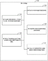
Fig. 8 is a flow diagram illustrating another example method for managing an operating channel of a first RAT over a communication medium shared with a second RAT in accordance with the techniques described above. As a particular example, the first RAT may include LTE technology, the second RAT may include Wi-Fi technology, and the operating channel may include a channel in an unlicensed frequency band. Method 800 may be performed by, for example, an access point (e.g., access point 110 shown in fig. 1).
As shown, the access point may perform (e.g., via one or more transceivers, such as RAT a transceiver 140 and/or RAT B transceiver 142, etc.) a scan of available channels (block 802). Based on the channel scan, the access point may select (e.g., via a channel selector such as channel selector 402, etc.) one of the available channels as an operating channel of the first RAT (block 804). The access point may also determine (e.g., via an interference analyzer such as interference analyzer 404, etc.) a utilization metric for the operating channel (block 806). The access point may then trigger (e.g., via an operating mode controller such as operating mode controller 406, etc.) a TDM pattern on the operating channel in response to the utilization metric being above the threshold (block 808). The TDM pattern may be used to cycle between activated and deactivated periods of communication according to a TDM communication pattern.
As discussed in more detail above, the utilization metric may correspond to, for example, a measure of interference from signaling on an operating channel associated with the second RAT. Here, the signaling may correspond to one or more beacons on the primary or secondary channel that are associated with the second RAT and exceed the signal strength threshold. The triggering (block 808) may include triggering the TDM pattern with: (i) utilize a first set of parameters for the TDM pattern based on the one or more beacons exceeding a threshold number on the primary channel, or (ii) utilize a second set of parameters for the TDM pattern based on the one or more beacons exceeding a threshold number on the secondary channel.
The utilization metric may also correspond to, for example, a measure of interference from signaling associated with the first RAT on the operating channel. Here, the triggering (block 808) may include triggering the TDM pattern with: (i) identify, based on the signaling, that at least a threshold number of access points are operating according to the first RAT on the operating channel, utilizing a first set of parameters for the TDM pattern, or (ii) identify, based on the signaling, that less than the threshold number of access points are operating according to the first RAT on the operating channel, utilizing a second set of parameters for the TDM pattern.
In some designs, the access point may also optionally modify (e.g., via an operating mode controller such as operating mode controller 406, etc.) one or more parameters of the TDM pattern in response to the utilization metric being above the threshold (optional block 810). The modifying may include modifying one or more parameters of the TDM pattern at a next scheduled channel scan. The one or more parameters may include, for example, a duty cycle, a transmission power, or a cycle timing of the TDM pattern.
For convenience, access point 110 and access terminal 120 are illustrated in fig. 1 as including various components that may be configured in accordance with various examples described herein. It will be appreciated, however, that the illustrated blocks may be implemented in various ways. In some implementations, the components of fig. 1 may be implemented in one or more circuits, such as, for example, one or more processors and/or one or more ASICs (which may include one or more processors). Here, each circuit may use and/or include at least one memory component for storing information or executable code used by the circuit to provide the functionality.
Fig. 9-11 provide alternative illustrations of means for implementing an access point 110 and/or an access terminal 120 as represented as a series of interrelated functional modules.
Fig. 9 illustrates an example access point apparatus 900 that is represented as a series of interrelated functional modules. In at least some aspects, the module for performing 902 may correspond to, for example, a communication device or component thereof (e.g., communication device 112, etc.) as discussed herein. In at least some aspects, the means for receiving 904 may correspond to, for example, a communication device or component thereof (e.g., communication device 112, etc.) as discussed herein. In at least some aspects, the means for determining 906 may correspond to, for example, a communication controller or component thereof (e.g., communication controller 114, etc.) as discussed herein. In at least some aspects, the means for determining 908 may correspond to, for example, a communication controller or component thereof (e.g., communication controller 114, etc.) as discussed herein. In at least some aspects, the module for calculating 910 may correspond to, for example, a communication controller or component thereof (e.g., communication controller 114, etc.) as discussed herein. In at least some aspects, the module for selecting 912 may correspond to, for example, a communication controller or component thereof (e.g., communication controller 114, etc.) as discussed herein. In at least some aspects, the optional means 914 for aggregating can correspond to, for example, a communication controller or component thereof as discussed herein (e.g., communication controller 114, etc.).
Fig. 10 illustrates an example access point device 1000 represented as a series of interrelated functional modules. In at least some aspects, the means for receiving 1002 may correspond to, for example, a communication device or component thereof (e.g., communication device 112, etc.) as discussed herein. In at least some aspects, the means for determining 1004 may correspond to, for example, a communication controller or component thereof (e.g., communication controller 114, etc.) as discussed herein. In at least some aspects, the module for triggering 1006 may correspond to, for example, a communication controller or component thereof (e.g., communication controller 114, etc.) as discussed herein. In at least some aspects, the means for selecting 1008 may correspond to, for example, a communication controller or component thereof (e.g., communication controller 114, etc.) as discussed herein.
Fig. 11 illustrates an example access point apparatus 1100 that is represented as a series of interrelated functional modules. In at least some aspects, the means for performing 1102 may correspond to, for example, a communication device or component thereof (e.g., communication device 112, etc.) as discussed herein. In at least some aspects, the means for selecting 1104 may correspond to, for example, a communication controller or component thereof (e.g., communication controller 114, etc.) as discussed herein. In at least some aspects, the means for determining 1106 may correspond to, for example, a communication controller or component thereof (e.g., communication controller 114, etc.) as discussed herein. In at least some aspects, the means for triggering 1108 may correspond to, for example, a communication controller or component thereof (e.g., communication controller 114, etc.) as discussed herein. In at least some aspects, optional means for modifying 1110 may correspond to, for example, a communication controller or component thereof (e.g., communication controller 114, etc.) as discussed herein.
The functionality of the modules of fig. 9-11 may be implemented in a variety of ways consistent with the teachings herein. In some designs, the functionality of these modules may be implemented as one or more electrical components. In some designs, the functionality of these blocks may be implemented as a processing system including one or more processor components. In some designs, the functionality of these modules may be implemented using, for example, at least a portion of one or more integrated circuits (e.g., an ASIC). As discussed herein, an integrated circuit may include a processor, software, other related components, or some combination thereof. Thus, the functionality of different modules may be implemented, for example, as different subsets of an integrated circuit, as different subsets of a set of software modules, or as a combination thereof. Further, it will be appreciated that a given subset (e.g., a given subset of an integrated circuit and/or a given subset of a set of software modules) may provide at least a portion of the functionality for more than one module.
Further, the components and functions represented in fig. 9-11, as well as other components and functions described herein, may be implemented using any suitable means. Such units may also be implemented, at least in part, using corresponding structures as taught herein. For example, the components described above in connection with the "module for … …" component of fig. 9-11 may also correspond to similarly designated "unit for … …" functionality. Thus, in some aspects, one or more of such units may be implemented using one or more of a processor, a component, an integrated circuit, other suitable structure as taught herein.
It will be understood that the use of, for example, "first," "second," etc., herein indicates that any reference to an element does not generally limit the number or order of elements described. Rather, these representations may be used herein as a convenient method of distinguishing between two or more elements or instances of an element. Thus, references to first and second elements do not imply that only two elements may be used or that the first element must somehow precede the second element. Further, a set of elements may include one or more elements unless otherwise specified. Furthermore, as used in the specification or claims, terms in the form of "at least one of A, B or C" or "one or more of A, B or C" or "at least one of the group consisting of A, B and C" mean "a or B or C or any combination of these elements. For example, the term may include A, or B, or C, or A and B, or A and C, or A and B and C, or 2A, or 2B, or 2C, and the like.
In view of the above description and explanation, those skilled in the art will appreciate that the various illustrative logical blocks, modules, circuits, and algorithm steps described in connection with the aspects disclosed herein may be implemented as electronic hardware, computer software, or combinations of both. To clearly illustrate this interchangeability of hardware and software, various illustrative components, blocks, modules, circuits, and steps have been described above generally in terms of their functionality. Whether such functionality is implemented as hardware or software depends upon the particular application and design constraints imposed on the overall system. Skilled artisans may implement the described functionality in varying ways for each particular application, but such implementation decisions should not be interpreted as causing a departure from the scope of the present disclosure.
Thus, it will be appreciated that the apparatus or any component of the apparatus may be configured (or made operative or adapted) to provide functionality as taught herein, for example. This can be achieved, for example, in the following way: fabricating (e.g., fabricating) a device or component such that it will provide the described functionality; programming the device and components such that they will provide the described functionality; or by using some other suitable implementation technique. In one example, an integrated circuit may be fabricated to provide the necessary functionality. As another example, an integrated circuit may be manufactured to support the necessary functionality and then configured (e.g., via programming) to provide the necessary functionality. As another example, a processor circuit may execute code to provide the necessary functionality.
Furthermore, the methods, sequences and/or algorithms described in connection with the aspects disclosed herein may be embodied directly in hardware, in a software module executed by a processor, or in a combination of the two. A software module may reside in Random Access Memory (RAM), flash memory, Read Only Memory (ROM), Erasable Programmable Read Only Memory (EPROM), Electrically Erasable Programmable Read Only Memory (EEPROM), registers, a hard disk, a removable disk, a CD-ROM, or any other form of storage medium known in the art. An exemplary storage medium is coupled to the processor such the processor can read information from, and write information to, the storage medium. In the alternative, the storage medium may be integral to the processor (e.g., cache memory).
Thus, it will also be appreciated that certain aspects of the disclosure may include, for example, transitory or non-transitory computer-readable media embodying methods for communication management between RATs sharing operating spectrum in unlicensed radio frequency bands. By way of example, such computer-readable media may comprise: code for performing a scan of available channels at an access point; code for receiving a channel measurement report for an available channel from an access terminal; code for determining a penalty metric for each of the available channels based on the channel scan; code for determining a utility metric for each of the available channels based on the channel measurement reports; code for calculating a cost function for each of the available channels based on the respective penalty metrics and the respective utility metrics; and code for selecting one of the available channels as an operating channel based on a comparison of the cost functions for each of the available channels. As another example, such a computer-readable medium may include: code for receiving one or more channel measurement reports for a current operating channel of a first RAT from each of a plurality of access terminals; code for determining a channel quality metric for a current operating channel based on the channel measurement report; code for triggering a channel scan in response to the channel quality metric indicating poor service for a threshold number or proportion of access terminals; and code for selecting a new operating channel based on the channel scan. As another example, such a computer-readable medium may include: code for performing a scan of available channels at an access point; code for selecting one of the available channels as an operating channel of the first RAT based on the channel scan; code for determining a utilization metric for an operating channel; and code for triggering a TDM pattern on the operating channel in response to the utilization metric being above the threshold, wherein the TDM pattern cycles operation between activated periods and deactivated periods of communication in accordance with the TDM communication pattern.
While the foregoing disclosure shows various illustrative aspects, it should be noted that various changes and modifications could be made to the examples shown without departing from the scope as defined by the appended claims. The present disclosure is not intended to be limited to the specifically described examples alone. For example, the functions, steps, and/or actions of the method claims in accordance with the aspects of the disclosure described herein need not be performed in any particular order unless otherwise specified. Furthermore, although elements disclosed may be described or claimed in the singular, the plural is contemplated unless limitation to the singular is explicitly stated.
Claims (30)
1. An access point apparatus for managing an operating channel of a first Radio Access Technology (RAT) over a communication medium shared with a second RAT, comprising:
a transceiver configured to receive one or more channel measurement reports for a current operating channel of the first RAT from each of a plurality of access terminals;
a channel quality analyzer configured to determine a channel quality metric for the current operating channel based on the channel measurement report;
a channel scanner configured to trigger a channel scan in response to the channel quality metric indicating poor service for a threshold number or proportion of the access terminals; and
a channel selector configured to select a new operating channel based on the channel scan.
2. The access point apparatus of claim 1, wherein the poor service corresponds to a service level below a service level threshold.
3. The access point apparatus of claim 2, wherein the service level threshold corresponds to a predetermined minimum service level.
4. The access point apparatus of claim 2, wherein the service level threshold corresponds to a dynamic minimum service level derived from: (i) a desired level of service based on the first RAT signaling; and (ii) an offset value.
5. The access point apparatus of claim 1, wherein said channel selector is further configured to dynamically set said threshold number or proportion of said access terminals.
6. The access point apparatus of claim 1, wherein the threshold number or proportion of the access terminals is more than one access terminal.
7. The access point apparatus of claim 1, wherein the channel scanner is configured to trigger the channel scan further in response to the channel quality metric indicating the poor service within a threshold amount of time.
8. The access point apparatus of claim 7, wherein the channel scanner is further configured to set the threshold amount of time based on a Discontinuous Reception (DRX) configuration of the access terminal.
9. The access point apparatus of claim 1, wherein the channel quality analyzer is configured to determine the channel quality metric based on a Channel Quality Indicator (CQI), a Packet Error Rate (PER), a Modulation and Coding Scheme (MCS), or a combination thereof, from the channel measurement report.
10. The access point apparatus of claim 1, wherein the new operating channel is different from the current operating channel.
11. The access point apparatus of claim 1, wherein the new operating channel is the same as the current operating channel.
12. The access point device of claim 1, wherein:
the first RAT comprises a Long Term Evolution (LTE) technology;
the second RAT comprises Wi-Fi technology; and
the operating channel comprises a channel in an unlicensed frequency band.
13. A method for managing an operating channel of a first Radio Access Technology (RAT) over a communication medium shared with a second RAT, comprising:
receiving one or more channel measurement reports for a current operating channel of the first RAT from each of a plurality of access terminals;
determining a channel quality metric for the current operating channel based on the channel measurement report;
triggering a channel scan in response to the channel quality metric indicating poor service for a threshold number or proportion of the access terminals; and
selecting a new operating channel based on the channel scan.
14. The method of claim 13, wherein the poor service corresponds to a service level below a service level threshold.
15. The method of claim 14, wherein the service level threshold corresponds to a predetermined minimum service level.
16. The method of claim 14, wherein the service level threshold corresponds to a dynamic minimum service level derived from: (i) a desired level of service based on the first RAT signaling; and (ii) an offset value.
17. The method of claim 13, further comprising: dynamically setting the threshold number or proportion of the access terminals.
18. The method of claim 13, wherein the threshold number or proportion of the access terminals is more than one access terminal.
19. The method of claim 13, wherein the triggering of the channel scan is further in response to the channel quality metric indicating the poor service within a threshold amount of time.
20. The method of claim 19, further comprising: setting the threshold amount of time based on a Discontinuous Reception (DRX) configuration of the access terminal.
21. The method of claim 13, wherein the determination of the channel quality metric is based on a Channel Quality Indicator (CQI), a Packet Error Rate (PER), a Modulation and Coding Scheme (MCS), or a combination thereof, from the channel measurement report.
22. The method of claim 13, wherein the new operating channel is different from the current operating channel.
23. The method of claim 13, wherein the new operating channel is the same as the current operating channel.
24. The method of claim 13, wherein:
the first RAT comprises a Long Term Evolution (LTE) technology;
the second RAT comprises Wi-Fi technology; and
the operating channel comprises a channel in an unlicensed frequency band.
25. An apparatus for managing an operating channel of a first Radio Access Technology (RAT) over a communication medium shared with a second RAT, comprising:
means for receiving one or more channel measurement reports for a current operating channel of the first RAT from each of a plurality of access terminals;
means for determining a channel quality metric for the current operating channel based on the channel measurement report;
means for triggering a channel scan in response to the channel quality metric indicating poor service for a threshold number or proportion of the access terminals; and
means for selecting a new operating channel based on the channel scan.
26. The apparatus of claim 25, wherein the poor service corresponds to a service level below a service level threshold.
27. The apparatus of claim 25, wherein the means for determining the channel quality metric comprises: means for determining the channel quality metric based on a Channel Quality Indicator (CQI), a Packet Error Rate (PER), a Modulation and Coding Scheme (MCS), or a combination thereof from the channel measurement report.
28. A computer-readable medium having code stored thereon, which, when executed by a processor, causes the processor to perform operations for managing an operating channel of a first Radio Access Technology (RAT) over a communication medium shared with a second RAT, the operations comprising:
receiving one or more channel measurement reports for a current operating channel of the first RAT from each of a plurality of access terminals;
determining a channel quality metric for the current operating channel based on the channel measurement report;
triggering a channel scan in response to the channel quality metric indicating poor service for a threshold number or proportion of the access terminals; and
selecting a new operating channel based on the channel scan.
29. The computer-readable medium of claim 28, wherein the poor service corresponds to a service level below a service level threshold.
30. The computer-readable medium of claim 28, wherein the determining the channel quality metric comprises: determining the channel quality metric based on a Channel Quality Indicator (CQI), a Packet Error Rate (PER), a Modulation and Coding Scheme (MCS), or a combination thereof from the channel measurement report.
Applications Claiming Priority (7)
| Application Number | Priority Date | Filing Date | Title |
|---|---|---|---|
| US201461981564P | 2014-04-18 | 2014-04-18 | |
| US61/981,564 | 2014-04-18 | ||
| US201462013412P | 2014-06-17 | 2014-06-17 | |
| US62/013,412 | 2014-06-17 | ||
| US14/687,411 | 2015-04-15 | ||
| US14/687,411 US10602527B2 (en) | 2014-04-18 | 2015-04-15 | Channel selection scanning in shared spectrum |
| PCT/US2015/026227 WO2015161109A1 (en) | 2014-04-18 | 2015-04-16 | Channel selection scanning in shared spectrum |
Publications (2)
| Publication Number | Publication Date |
|---|---|
| CN106576350A CN106576350A (en) | 2017-04-19 |
| CN106576350B true CN106576350B (en) | 2020-11-03 |
Family
ID=54323188
Family Applications (3)
| Application Number | Title | Priority Date | Filing Date |
|---|---|---|---|
| CN201580019942.7A Active CN106576351B (en) | 2014-04-18 | 2015-04-16 | Channel selection metrics in a shared spectrum |
| CN201580019986.XA Active CN106233763B (en) | 2014-04-18 | 2015-04-16 | Channel selection in shared frequency spectrum coexists |
| CN201580019935.7A Active CN106576350B (en) | 2014-04-18 | 2015-04-16 | Channel selection scanning in shared spectrum |
Family Applications Before (2)
| Application Number | Title | Priority Date | Filing Date |
|---|---|---|---|
| CN201580019942.7A Active CN106576351B (en) | 2014-04-18 | 2015-04-16 | Channel selection metrics in a shared spectrum |
| CN201580019986.XA Active CN106233763B (en) | 2014-04-18 | 2015-04-16 | Channel selection in shared frequency spectrum coexists |
Country Status (7)
| Country | Link |
|---|---|
| US (3) | US10602527B2 (en) |
| EP (3) | EP3132643B1 (en) |
| JP (3) | JP6469722B2 (en) |
| KR (3) | KR101910726B1 (en) |
| CN (3) | CN106576351B (en) |
| BR (3) | BR112016024254A2 (en) |
| WO (3) | WO2015161109A1 (en) |
Families Citing this family (26)
| Publication number | Priority date | Publication date | Assignee | Title |
|---|---|---|---|---|
| US10979203B2 (en) | 2013-09-04 | 2021-04-13 | Qualcomm Incorporated | Channel selection to reduce interference to a wireless local area network from a cellular network |
| US10602527B2 (en) | 2014-04-18 | 2020-03-24 | Qualcomm Incorporated | Channel selection scanning in shared spectrum |
| US10206129B2 (en) * | 2014-09-16 | 2019-02-12 | Empire Technology Development Llc | Cellular range expansion of base station |
| KR102565155B1 (en) * | 2016-01-27 | 2023-08-10 | 삼성전자주식회사 | Method and apparatus for measuring a channel in a wireless communication system |
| WO2018058325A1 (en) * | 2016-09-27 | 2018-04-05 | 深圳市大疆创新科技有限公司 | Channel parameter displaying method and apparatus, and control terminal |
| US10938523B2 (en) | 2016-10-13 | 2021-03-02 | Netally, Llc | WLAN RF environment evaluation for 802.11ac channels |
| WO2018087663A1 (en) * | 2016-11-08 | 2018-05-17 | Telefonaktiebolaget Lm Ericsson (Publ) | A method and a controlling node for controlling resources in a shared channel |
| CN108235345B (en) * | 2016-12-22 | 2021-06-08 | 上海诺基亚贝尔股份有限公司 | Method and device for determining low-quality area in cell |
| EP3571811A1 (en) | 2017-01-20 | 2019-11-27 | Airties Kablosuz Lietisim Sanayi Ve Dis Ticaret A.S | Cloud controlled mesh networking |
| US10111228B2 (en) * | 2017-03-16 | 2018-10-23 | Cognitive Systems Corp. | Selecting wireless communication channels based on signal quality metrics |
| TWI677256B (en) | 2017-05-01 | 2019-11-11 | 宏達國際電子股份有限公司 | Device and method of handling a channel access procedure |
| WO2018201463A1 (en) | 2017-05-05 | 2018-11-08 | SZ DJI Technology Co., Ltd. | Working wireless communication channel selection based on spectral estimation |
| CN107318168B (en) * | 2017-06-21 | 2020-07-24 | 深圳市盛路物联通讯技术有限公司 | Method and system for controlling communication of terminal equipment of Internet of things |
| KR101979278B1 (en) | 2017-09-28 | 2019-05-16 | 엘지전자 주식회사 | Control method of air-conditioner system |
| KR101922954B1 (en) | 2017-09-28 | 2018-11-28 | 엘지전자 주식회사 | Control method of air-conditioner system |
| US10667274B2 (en) * | 2018-06-29 | 2020-05-26 | Wipro Limited | Method and system for dynamic channel allocation in long-range land-to-sea (LRLS) wireless communication |
| CN108566683B (en) * | 2018-07-10 | 2020-01-10 | 北京邮电大学 | Method and device for accessing unauthorized frequency band, electronic equipment and readable storage medium |
| EP3641373B1 (en) * | 2018-10-16 | 2021-09-15 | Advanced Digital Broadcast S.A. | System and method for determining communication channels in a wireless network |
| US10455488B1 (en) | 2019-02-15 | 2019-10-22 | At&T Intellectual Property I, L.P. | Discontinuous access to unlicensed spectrum in a new radio environment |
| US11234173B2 (en) * | 2019-05-09 | 2022-01-25 | Cisco Technology, Inc. | Serving internet of things (IoT) devices in a wireless network |
| US11259210B2 (en) * | 2020-01-13 | 2022-02-22 | Mediatek Inc. | Methods for data traffic switching and network selection |
| CN112399522B (en) * | 2020-10-12 | 2022-09-13 | 北京通广龙电子科技有限公司 | Topology control method, electronic device, and storage medium |
| CN112532310B (en) * | 2020-12-21 | 2022-11-15 | 国网浙江省电力有限公司信息通信分公司 | Satellite emergency communication and ubiquitous satellite Internet of things spectrum sharing method and device |
| US11659588B1 (en) * | 2021-01-27 | 2023-05-23 | Amazon Technologies, Inc. | Multi-tier coordinated channel prioritization system |
| EP4333537A1 (en) * | 2022-08-31 | 2024-03-06 | Advanced Digital Broadcast S.A. | A method for selecting a wireless channel to prevent interferences |
| WO2024079659A1 (en) * | 2022-10-11 | 2024-04-18 | Airties S.A.S. | Dynamic coordinated channel allocation system for clusters of wireless networks |
Family Cites Families (57)
| Publication number | Priority date | Publication date | Assignee | Title |
|---|---|---|---|---|
| US5675629A (en) | 1995-09-08 | 1997-10-07 | At&T | Cordless cellular system base station |
| US5963848A (en) | 1996-04-24 | 1999-10-05 | Motorola, Inc. | Method and apparatus for assigning a channel to a mobile unit in a wireless communication system |
| US6985465B2 (en) | 2000-07-07 | 2006-01-10 | Koninklijke Philips Electronics N.V. | Dynamic channel selection scheme for IEEE 802.11 WLANs |
| US7450943B2 (en) * | 2003-02-12 | 2008-11-11 | Qualcomm Incorporated | Method and apparatus for determining coverage and switching between overlay communication systems |
| US20040259555A1 (en) | 2003-04-23 | 2004-12-23 | Rappaport Theodore S. | System and method for predicting network performance and position location using multiple table lookups |
| US20050265288A1 (en) | 2004-05-27 | 2005-12-01 | Jiewen Liu | Apparatus and method capable of automatic allocation of operating channels in a wireless network |
| US9031568B2 (en) | 2004-07-28 | 2015-05-12 | Broadcom Corporation | Quality-of-service (QoS)-based association with a new network using background network scanning |
| ES2293868T3 (en) * | 2004-10-20 | 2012-11-02 | Qualcomm Incorporated | Operation in multiple frequency bands in wireless networks |
| US7684464B2 (en) * | 2004-12-21 | 2010-03-23 | Qualcomm Incorporated | Method and apparatus for performing channel assessment in a wireless communication system |
| US8498237B2 (en) | 2006-01-11 | 2013-07-30 | Qualcomm Incorporated | Methods and apparatus for communicating device capability and/or setup information |
| US8472998B2 (en) | 2006-09-05 | 2013-06-25 | Motorola Mobility Llc | System and method for achieving WLAN communications between access point and mobile device |
| US9265003B2 (en) | 2006-11-13 | 2016-02-16 | Qualcomm Incorporated | Apparatus and methods for reducing power consumption and/or radio frequency interference in a mobile computing device |
| WO2009055304A1 (en) | 2007-10-22 | 2009-04-30 | Marvell Semiconductor, Inc. | Location aware background access point scanning for wlan |
| US8139528B2 (en) | 2008-01-28 | 2012-03-20 | Qualcomm Incorporated | Adaptive transmission of resource utilization messages |
| US8457549B2 (en) | 2008-02-29 | 2013-06-04 | Lingna Holdings Pte., Llc | Multi-user MIMO relay protocol with self-interference cancellation |
| US8265017B2 (en) | 2008-04-11 | 2012-09-11 | Apple Inc. | Methods and apparatus for network capacity enhancement for wireless device coexistence |
| US8072896B2 (en) | 2008-04-18 | 2011-12-06 | Telefonaktiebolaget L M Ericsson (Publ) | Adaptive coexistence between different wireless communication systems |
| US20090310565A1 (en) | 2008-06-13 | 2009-12-17 | Fujitsu Microelectronics Limited | System And Method For Selecting Parameters In Wireless Communication |
| US8588148B2 (en) | 2008-06-13 | 2013-11-19 | Fujitsu Semiconductor Limited | System and method for selecting channels in wireless communication |
| US8577377B2 (en) | 2009-01-22 | 2013-11-05 | Qualcomm Incorporated | Methods and apparatus for providing a wireless expansion network |
| US8675623B2 (en) * | 2009-02-01 | 2014-03-18 | Qualcomm Incorporated | Distributed prioritized contention for spectrum sharing |
| CN101521924B (en) * | 2009-04-27 | 2011-11-16 | 杭州华三通信技术有限公司 | Switching method and device of wireless local area network |
| US9210586B2 (en) | 2009-05-08 | 2015-12-08 | Qualcomm Incorporated | Method and apparatus for generating and exchanging information for coverage optimization in wireless networks |
| US8825053B2 (en) | 2009-05-11 | 2014-09-02 | Telefonaktiebolaget L M Ericsson (Publ) | Technique for instructing mobile stations communicating with cooperating access nodes |
| US8588149B2 (en) | 2009-06-12 | 2013-11-19 | Fujitsu Semiconductor Limited | System and method for adjusting channels in wireless communication |
| US8938238B2 (en) * | 2009-11-06 | 2015-01-20 | Qualcomm Incorporated | Restricting access point transmissions |
| US8848607B2 (en) | 2010-03-30 | 2014-09-30 | Qualcomm Incorporated | Method and apparatus to facilitate support for multi-radio coexistence |
| KR101637587B1 (en) | 2010-04-07 | 2016-07-07 | 엘지전자 주식회사 | METHOD FOR CONTROLLING CONNECTION AT Femto Base station and Connection METHOD AT Terminal |
| US8737924B2 (en) | 2010-08-12 | 2014-05-27 | Mediatek Inc. | Method to trigger in-device coexistence interference mitigation in mobile cellular systems |
| EP2609772A4 (en) | 2010-08-26 | 2016-08-24 | Ericsson Telefon Ab L M | Method and network node in a communications system |
| US9002277B2 (en) | 2010-09-07 | 2015-04-07 | Aerohive Networks, Inc. | Distributed channel selection for wireless networks |
| CA2808472C (en) | 2010-09-23 | 2016-10-11 | Research In Motion Limited | System and method for dynamic coordination of radio resources usage in a wireless network environment |
| US8780880B2 (en) * | 2010-10-01 | 2014-07-15 | Mediatek Singapore Pte, Ltd. | Method of TDM in-device coexistence interference avoidance |
| SI2641427T1 (en) | 2010-11-17 | 2021-01-29 | Aviat Networks, Inc. | Systems and methods of backhaul optimization |
| KR101794058B1 (en) | 2011-03-08 | 2017-12-04 | 삼성전자주식회사 | Wireless Network Channel Allocation Method For Interference Avoidance |
| US8798566B2 (en) | 2011-03-30 | 2014-08-05 | Texas Instruments Incorporated | Rapid autonomous scan in FM or other receivers with parallel search strategy, and circuits, processes and systems |
| US8971813B2 (en) | 2011-04-26 | 2015-03-03 | Broadcom Corporation | Method and apparatus for avoiding in-device interference |
| US9161273B2 (en) | 2011-09-06 | 2015-10-13 | Intel Corporation | Small cells implementing multiple air interfaces |
| US9055588B2 (en) * | 2011-09-06 | 2015-06-09 | Qualcomm Incorporated | Methods and apparatus for identifying and/or selecting channels |
| BR112014007959A2 (en) | 2011-10-03 | 2017-06-13 | Intel Corp | mechanisms for device to device communication |
| WO2013067668A1 (en) | 2011-11-07 | 2013-05-16 | Empire Technology Development Llc | Tdma-based self-adaptive channel-switching |
| KR20140113976A (en) | 2011-12-22 | 2014-09-25 | 인터디지탈 패튼 홀딩스, 인크 | Methods, apparatus, and systems for dynamic spectrum allocation |
| EP2813121A2 (en) | 2012-01-11 | 2014-12-17 | Interdigital Patent Holdings, Inc. | Adaptive control channel |
| JP6309900B2 (en) | 2012-01-26 | 2018-04-11 | インターデイジタル パテント ホールディングス インコーポレイテッド | Dynamic parameter adjustment for LTE coexistence |
| WO2013116857A1 (en) | 2012-02-03 | 2013-08-08 | Eden Rock Communications, Llc | Method and apparatus for measuring multi-cell data efficiency in link adaptive wireless networks |
| US9031592B2 (en) | 2012-03-31 | 2015-05-12 | Tejas Networks Limited | Method and system for cancelling adjacent cells interference signal in a wireless communication system |
| US8874124B2 (en) | 2012-06-14 | 2014-10-28 | Netgear, Inc. | Dual band LTE small cell |
| US9184886B2 (en) | 2012-08-10 | 2015-11-10 | Blackberry Limited | TD LTE secondary component carrier in unlicensed bands |
| EP2898724B1 (en) | 2012-09-24 | 2017-12-20 | Interdigital Patent Holdings, Inc. | Channel quality measurement and transmit power allocation in a dynamic spectrum management system |
| CN103813368B (en) | 2012-11-12 | 2017-09-15 | 中国移动通信集团公司 | A kind of method, apparatus and system being monitored to network operation state |
| CN103582081B (en) | 2013-08-30 | 2017-04-19 | 英特尔公司 | Device and method used for access detection switching |
| US9768929B2 (en) * | 2012-12-21 | 2017-09-19 | Blackberry Limited | Method and apparatus for identifying interference type in time division duplex systems |
| US10979203B2 (en) | 2013-09-04 | 2021-04-13 | Qualcomm Incorporated | Channel selection to reduce interference to a wireless local area network from a cellular network |
| US9264968B2 (en) | 2013-12-03 | 2016-02-16 | Apple Inc. | Device to device communications with carrier aggregation |
| US9497699B2 (en) | 2014-03-31 | 2016-11-15 | Qualcomm Incorporated | Dedicated channel for fast initial link setup in a wireless network |
| US10602527B2 (en) | 2014-04-18 | 2020-03-24 | Qualcomm Incorporated | Channel selection scanning in shared spectrum |
| US9847962B2 (en) | 2014-07-29 | 2017-12-19 | Futurewei Technologies, Inc. | Device, network, and method for communications with spatial-specific sensing |
-
2015
- 2015-04-15 US US14/687,411 patent/US10602527B2/en active Active
- 2015-04-15 US US14/687,600 patent/US10743325B2/en active Active
- 2015-04-15 US US14/687,264 patent/US9986574B2/en active Active
- 2015-04-16 WO PCT/US2015/026227 patent/WO2015161109A1/en active Application Filing
- 2015-04-16 WO PCT/US2015/026203 patent/WO2015161096A1/en active Application Filing
- 2015-04-16 JP JP2016562527A patent/JP6469722B2/en active Active
- 2015-04-16 WO PCT/US2015/026238 patent/WO2015161116A1/en active Application Filing
- 2015-04-16 EP EP15720838.0A patent/EP3132643B1/en active Active
- 2015-04-16 BR BR112016024254A patent/BR112016024254A2/en not_active IP Right Cessation
- 2015-04-16 CN CN201580019942.7A patent/CN106576351B/en active Active
- 2015-04-16 KR KR1020167030107A patent/KR101910726B1/en active IP Right Grant
- 2015-04-16 EP EP15720839.8A patent/EP3132644B1/en active Active
- 2015-04-16 BR BR112016024283A patent/BR112016024283A2/en not_active IP Right Cessation
- 2015-04-16 CN CN201580019986.XA patent/CN106233763B/en active Active
- 2015-04-16 JP JP2016562246A patent/JP6568870B2/en active Active
- 2015-04-16 KR KR1020167030106A patent/KR101910725B1/en active IP Right Grant
- 2015-04-16 CN CN201580019935.7A patent/CN106576350B/en active Active
- 2015-04-16 BR BR112016024230A patent/BR112016024230A2/en not_active IP Right Cessation
- 2015-04-16 JP JP2016562240A patent/JP6378362B2/en active Active
- 2015-04-16 EP EP15718415.1A patent/EP3132642A1/en not_active Withdrawn
- 2015-04-16 KR KR1020167030105A patent/KR101911159B1/en active IP Right Grant
Also Published As
Similar Documents
| Publication | Publication Date | Title |
|---|---|---|
| CN106576350B (en) | Channel selection scanning in shared spectrum | |
| CN108781421B (en) | Coordination of operating modes on a shared communication medium | |
| US9750014B2 (en) | Interlaced carrier sense adaptive transmission (CSAT) co-existence in shared spectrum | |
| EP3162131B1 (en) | Improving cca clearance in unlicensed spectrum | |
| US9729299B2 (en) | Methods and systems for communication in dense wireless environments | |
| WO2015034944A1 (en) | Robust inter-radio access technology operations in unlicensed spectrum | |
| US9806836B2 (en) | Co-existence-aware communication in shared spectrum | |
| US20170086076A1 (en) | Setting transmission parameters in shared spectrum | |
| US20170366979A1 (en) | Radio access technology (rat) prioritization on a shared communication medium | |
| US9999094B2 (en) | Wakeup schedule coordination on a shared communication medium |
Legal Events
| Date | Code | Title | Description |
|---|---|---|---|
| PB01 | Publication | ||
| PB01 | Publication | ||
| SE01 | Entry into force of request for substantive examination | ||
| SE01 | Entry into force of request for substantive examination | ||
| GR01 | Patent grant | ||
| GR01 | Patent grant |