CN106456855B - Percutaneous systems, devices and methods - Google Patents
Percutaneous systems, devices and methods Download PDFInfo
- Publication number
- CN106456855B CN106456855B CN201580004854.XA CN201580004854A CN106456855B CN 106456855 B CN106456855 B CN 106456855B CN 201580004854 A CN201580004854 A CN 201580004854A CN 106456855 B CN106456855 B CN 106456855B
- Authority
- CN
- China
- Prior art keywords
- connector
- compartment
- fluid
- anatomical
- flow
- Prior art date
- Legal status (The legal status is an assumption and is not a legal conclusion. Google has not performed a legal analysis and makes no representation as to the accuracy of the status listed.)
- Active
Links
Images


Classifications
-
- A—HUMAN NECESSITIES
- A61—MEDICAL OR VETERINARY SCIENCE; HYGIENE
- A61B—DIAGNOSIS; SURGERY; IDENTIFICATION
- A61B17/00—Surgical instruments, devices or methods, e.g. tourniquets
- A61B17/00234—Surgical instruments, devices or methods, e.g. tourniquets for minimally invasive surgery
-
- A—HUMAN NECESSITIES
- A61—MEDICAL OR VETERINARY SCIENCE; HYGIENE
- A61B—DIAGNOSIS; SURGERY; IDENTIFICATION
- A61B17/00—Surgical instruments, devices or methods, e.g. tourniquets
- A61B17/11—Surgical instruments, devices or methods, e.g. tourniquets for performing anastomosis; Buttons for anastomosis
-
- A—HUMAN NECESSITIES
- A61—MEDICAL OR VETERINARY SCIENCE; HYGIENE
- A61B—DIAGNOSIS; SURGERY; IDENTIFICATION
- A61B17/00—Surgical instruments, devices or methods, e.g. tourniquets
- A61B17/34—Trocars; Puncturing needles
- A61B17/3468—Trocars; Puncturing needles for implanting or removing devices, e.g. prostheses, implants, seeds, wires
-
- A—HUMAN NECESSITIES
- A61—MEDICAL OR VETERINARY SCIENCE; HYGIENE
- A61B—DIAGNOSIS; SURGERY; IDENTIFICATION
- A61B17/00—Surgical instruments, devices or methods, e.g. tourniquets
- A61B17/34—Trocars; Puncturing needles
- A61B17/3478—Endoscopic needles, e.g. for infusion
-
- A—HUMAN NECESSITIES
- A61—MEDICAL OR VETERINARY SCIENCE; HYGIENE
- A61F—FILTERS IMPLANTABLE INTO BLOOD VESSELS; PROSTHESES; DEVICES PROVIDING PATENCY TO, OR PREVENTING COLLAPSING OF, TUBULAR STRUCTURES OF THE BODY, e.g. STENTS; ORTHOPAEDIC, NURSING OR CONTRACEPTIVE DEVICES; FOMENTATION; TREATMENT OR PROTECTION OF EYES OR EARS; BANDAGES, DRESSINGS OR ABSORBENT PADS; FIRST-AID KITS
- A61F2/00—Filters implantable into blood vessels; Prostheses, i.e. artificial substitutes or replacements for parts of the body; Appliances for connecting them with the body; Devices providing patency to, or preventing collapsing of, tubular structures of the body, e.g. stents
- A61F2/02—Prostheses implantable into the body
- A61F2/24—Heart valves ; Vascular valves, e.g. venous valves; Heart implants, e.g. passive devices for improving the function of the native valve or the heart muscle; Transmyocardial revascularisation [TMR] devices; Valves implantable in the body
- A61F2/2427—Devices for manipulating or deploying heart valves during implantation
- A61F2/2436—Deployment by retracting a sheath
-
- A—HUMAN NECESSITIES
- A61—MEDICAL OR VETERINARY SCIENCE; HYGIENE
- A61M—DEVICES FOR INTRODUCING MEDIA INTO, OR ONTO, THE BODY; DEVICES FOR TRANSDUCING BODY MEDIA OR FOR TAKING MEDIA FROM THE BODY; DEVICES FOR PRODUCING OR ENDING SLEEP OR STUPOR
- A61M27/00—Drainage appliance for wounds or the like, i.e. wound drains, implanted drains
- A61M27/002—Implant devices for drainage of body fluids from one part of the body to another
-
- A—HUMAN NECESSITIES
- A61—MEDICAL OR VETERINARY SCIENCE; HYGIENE
- A61M—DEVICES FOR INTRODUCING MEDIA INTO, OR ONTO, THE BODY; DEVICES FOR TRANSDUCING BODY MEDIA OR FOR TAKING MEDIA FROM THE BODY; DEVICES FOR PRODUCING OR ENDING SLEEP OR STUPOR
- A61M29/00—Dilators with or without means for introducing media, e.g. remedies
-
- A—HUMAN NECESSITIES
- A61—MEDICAL OR VETERINARY SCIENCE; HYGIENE
- A61M—DEVICES FOR INTRODUCING MEDIA INTO, OR ONTO, THE BODY; DEVICES FOR TRANSDUCING BODY MEDIA OR FOR TAKING MEDIA FROM THE BODY; DEVICES FOR PRODUCING OR ENDING SLEEP OR STUPOR
- A61M60/00—Blood pumps; Devices for mechanical circulatory actuation; Balloon pumps for circulatory assistance
- A61M60/10—Location thereof with respect to the patient's body
- A61M60/122—Implantable pumps or pumping devices, i.e. the blood being pumped inside the patient's body
- A61M60/126—Implantable pumps or pumping devices, i.e. the blood being pumped inside the patient's body implantable via, into, inside, in line, branching on, or around a blood vessel
- A61M60/135—Implantable pumps or pumping devices, i.e. the blood being pumped inside the patient's body implantable via, into, inside, in line, branching on, or around a blood vessel inside a blood vessel, e.g. using grafting
-
- A—HUMAN NECESSITIES
- A61—MEDICAL OR VETERINARY SCIENCE; HYGIENE
- A61M—DEVICES FOR INTRODUCING MEDIA INTO, OR ONTO, THE BODY; DEVICES FOR TRANSDUCING BODY MEDIA OR FOR TAKING MEDIA FROM THE BODY; DEVICES FOR PRODUCING OR ENDING SLEEP OR STUPOR
- A61M60/00—Blood pumps; Devices for mechanical circulatory actuation; Balloon pumps for circulatory assistance
- A61M60/10—Location thereof with respect to the patient's body
- A61M60/122—Implantable pumps or pumping devices, i.e. the blood being pumped inside the patient's body
- A61M60/126—Implantable pumps or pumping devices, i.e. the blood being pumped inside the patient's body implantable via, into, inside, in line, branching on, or around a blood vessel
- A61M60/148—Implantable pumps or pumping devices, i.e. the blood being pumped inside the patient's body implantable via, into, inside, in line, branching on, or around a blood vessel in line with a blood vessel using resection or like techniques, e.g. permanent endovascular heart assist devices
-
- A—HUMAN NECESSITIES
- A61—MEDICAL OR VETERINARY SCIENCE; HYGIENE
- A61M—DEVICES FOR INTRODUCING MEDIA INTO, OR ONTO, THE BODY; DEVICES FOR TRANSDUCING BODY MEDIA OR FOR TAKING MEDIA FROM THE BODY; DEVICES FOR PRODUCING OR ENDING SLEEP OR STUPOR
- A61M60/00—Blood pumps; Devices for mechanical circulatory actuation; Balloon pumps for circulatory assistance
- A61M60/10—Location thereof with respect to the patient's body
- A61M60/122—Implantable pumps or pumping devices, i.e. the blood being pumped inside the patient's body
- A61M60/126—Implantable pumps or pumping devices, i.e. the blood being pumped inside the patient's body implantable via, into, inside, in line, branching on, or around a blood vessel
- A61M60/152—Implantable pumps or pumping devices, i.e. the blood being pumped inside the patient's body implantable via, into, inside, in line, branching on, or around a blood vessel branching on and drawing blood from a blood vessel
-
- A—HUMAN NECESSITIES
- A61—MEDICAL OR VETERINARY SCIENCE; HYGIENE
- A61M—DEVICES FOR INTRODUCING MEDIA INTO, OR ONTO, THE BODY; DEVICES FOR TRANSDUCING BODY MEDIA OR FOR TAKING MEDIA FROM THE BODY; DEVICES FOR PRODUCING OR ENDING SLEEP OR STUPOR
- A61M60/00—Blood pumps; Devices for mechanical circulatory actuation; Balloon pumps for circulatory assistance
- A61M60/10—Location thereof with respect to the patient's body
- A61M60/122—Implantable pumps or pumping devices, i.e. the blood being pumped inside the patient's body
- A61M60/165—Implantable pumps or pumping devices, i.e. the blood being pumped inside the patient's body implantable in, on, or around the heart
- A61M60/17—Implantable pumps or pumping devices, i.e. the blood being pumped inside the patient's body implantable in, on, or around the heart inside a ventricle, e.g. intraventricular balloon pumps
-
- A—HUMAN NECESSITIES
- A61—MEDICAL OR VETERINARY SCIENCE; HYGIENE
- A61M—DEVICES FOR INTRODUCING MEDIA INTO, OR ONTO, THE BODY; DEVICES FOR TRANSDUCING BODY MEDIA OR FOR TAKING MEDIA FROM THE BODY; DEVICES FOR PRODUCING OR ENDING SLEEP OR STUPOR
- A61M60/00—Blood pumps; Devices for mechanical circulatory actuation; Balloon pumps for circulatory assistance
- A61M60/20—Type thereof
- A61M60/205—Non-positive displacement blood pumps
- A61M60/216—Non-positive displacement blood pumps including a rotating member acting on the blood, e.g. impeller
-
- A—HUMAN NECESSITIES
- A61—MEDICAL OR VETERINARY SCIENCE; HYGIENE
- A61M—DEVICES FOR INTRODUCING MEDIA INTO, OR ONTO, THE BODY; DEVICES FOR TRANSDUCING BODY MEDIA OR FOR TAKING MEDIA FROM THE BODY; DEVICES FOR PRODUCING OR ENDING SLEEP OR STUPOR
- A61M60/00—Blood pumps; Devices for mechanical circulatory actuation; Balloon pumps for circulatory assistance
- A61M60/40—Details relating to driving
- A61M60/465—Details relating to driving for devices for mechanical circulatory actuation
- A61M60/489—Details relating to driving for devices for mechanical circulatory actuation the force acting on the actuation means being magnetic
-
- A—HUMAN NECESSITIES
- A61—MEDICAL OR VETERINARY SCIENCE; HYGIENE
- A61M—DEVICES FOR INTRODUCING MEDIA INTO, OR ONTO, THE BODY; DEVICES FOR TRANSDUCING BODY MEDIA OR FOR TAKING MEDIA FROM THE BODY; DEVICES FOR PRODUCING OR ENDING SLEEP OR STUPOR
- A61M60/00—Blood pumps; Devices for mechanical circulatory actuation; Balloon pumps for circulatory assistance
- A61M60/50—Details relating to control
- A61M60/508—Electronic control means, e.g. for feedback regulation
-
- A—HUMAN NECESSITIES
- A61—MEDICAL OR VETERINARY SCIENCE; HYGIENE
- A61M—DEVICES FOR INTRODUCING MEDIA INTO, OR ONTO, THE BODY; DEVICES FOR TRANSDUCING BODY MEDIA OR FOR TAKING MEDIA FROM THE BODY; DEVICES FOR PRODUCING OR ENDING SLEEP OR STUPOR
- A61M60/00—Blood pumps; Devices for mechanical circulatory actuation; Balloon pumps for circulatory assistance
- A61M60/80—Constructional details other than related to driving
- A61M60/802—Constructional details other than related to driving of non-positive displacement blood pumps
- A61M60/804—Impellers
- A61M60/806—Vanes or blades
-
- A—HUMAN NECESSITIES
- A61—MEDICAL OR VETERINARY SCIENCE; HYGIENE
- A61M—DEVICES FOR INTRODUCING MEDIA INTO, OR ONTO, THE BODY; DEVICES FOR TRANSDUCING BODY MEDIA OR FOR TAKING MEDIA FROM THE BODY; DEVICES FOR PRODUCING OR ENDING SLEEP OR STUPOR
- A61M60/00—Blood pumps; Devices for mechanical circulatory actuation; Balloon pumps for circulatory assistance
- A61M60/80—Constructional details other than related to driving
- A61M60/855—Constructional details other than related to driving of implantable pumps or pumping devices
- A61M60/857—Implantable blood tubes
-
- A—HUMAN NECESSITIES
- A61—MEDICAL OR VETERINARY SCIENCE; HYGIENE
- A61M—DEVICES FOR INTRODUCING MEDIA INTO, OR ONTO, THE BODY; DEVICES FOR TRANSDUCING BODY MEDIA OR FOR TAKING MEDIA FROM THE BODY; DEVICES FOR PRODUCING OR ENDING SLEEP OR STUPOR
- A61M60/00—Blood pumps; Devices for mechanical circulatory actuation; Balloon pumps for circulatory assistance
- A61M60/80—Constructional details other than related to driving
- A61M60/855—Constructional details other than related to driving of implantable pumps or pumping devices
- A61M60/861—Connections or anchorings for connecting or anchoring pumps or pumping devices to parts of the patient's body
-
- A—HUMAN NECESSITIES
- A61—MEDICAL OR VETERINARY SCIENCE; HYGIENE
- A61M—DEVICES FOR INTRODUCING MEDIA INTO, OR ONTO, THE BODY; DEVICES FOR TRANSDUCING BODY MEDIA OR FOR TAKING MEDIA FROM THE BODY; DEVICES FOR PRODUCING OR ENDING SLEEP OR STUPOR
- A61M60/00—Blood pumps; Devices for mechanical circulatory actuation; Balloon pumps for circulatory assistance
- A61M60/80—Constructional details other than related to driving
- A61M60/855—Constructional details other than related to driving of implantable pumps or pumping devices
- A61M60/871—Energy supply devices; Converters therefor
- A61M60/876—Implantable batteries
-
- A—HUMAN NECESSITIES
- A61—MEDICAL OR VETERINARY SCIENCE; HYGIENE
- A61B—DIAGNOSIS; SURGERY; IDENTIFICATION
- A61B17/00—Surgical instruments, devices or methods, e.g. tourniquets
- A61B17/00234—Surgical instruments, devices or methods, e.g. tourniquets for minimally invasive surgery
- A61B2017/00238—Type of minimally invasive operation
- A61B2017/00243—Type of minimally invasive operation cardiac
- A61B2017/00247—Making holes in the wall of the heart, e.g. laser Myocardial revascularization
- A61B2017/00252—Making holes in the wall of the heart, e.g. laser Myocardial revascularization for by-pass connections, i.e. connections from heart chamber to blood vessel or from blood vessel to blood vessel
-
- A—HUMAN NECESSITIES
- A61—MEDICAL OR VETERINARY SCIENCE; HYGIENE
- A61B—DIAGNOSIS; SURGERY; IDENTIFICATION
- A61B17/00—Surgical instruments, devices or methods, e.g. tourniquets
- A61B2017/00681—Aspects not otherwise provided for
- A61B2017/00685—Archimedes screw
-
- A—HUMAN NECESSITIES
- A61—MEDICAL OR VETERINARY SCIENCE; HYGIENE
- A61B—DIAGNOSIS; SURGERY; IDENTIFICATION
- A61B17/00—Surgical instruments, devices or methods, e.g. tourniquets
- A61B2017/00831—Material properties
- A61B2017/00867—Material properties shape memory effect
-
- A—HUMAN NECESSITIES
- A61—MEDICAL OR VETERINARY SCIENCE; HYGIENE
- A61B—DIAGNOSIS; SURGERY; IDENTIFICATION
- A61B17/00—Surgical instruments, devices or methods, e.g. tourniquets
- A61B2017/00831—Material properties
- A61B2017/00876—Material properties magnetic
-
- A—HUMAN NECESSITIES
- A61—MEDICAL OR VETERINARY SCIENCE; HYGIENE
- A61B—DIAGNOSIS; SURGERY; IDENTIFICATION
- A61B17/00—Surgical instruments, devices or methods, e.g. tourniquets
- A61B17/11—Surgical instruments, devices or methods, e.g. tourniquets for performing anastomosis; Buttons for anastomosis
- A61B2017/1107—Surgical instruments, devices or methods, e.g. tourniquets for performing anastomosis; Buttons for anastomosis for blood vessels
-
- A—HUMAN NECESSITIES
- A61—MEDICAL OR VETERINARY SCIENCE; HYGIENE
- A61B—DIAGNOSIS; SURGERY; IDENTIFICATION
- A61B17/00—Surgical instruments, devices or methods, e.g. tourniquets
- A61B17/11—Surgical instruments, devices or methods, e.g. tourniquets for performing anastomosis; Buttons for anastomosis
- A61B2017/1139—Side-to-side connections, e.g. shunt or X-connections
-
- A—HUMAN NECESSITIES
- A61—MEDICAL OR VETERINARY SCIENCE; HYGIENE
- A61B—DIAGNOSIS; SURGERY; IDENTIFICATION
- A61B17/00—Surgical instruments, devices or methods, e.g. tourniquets
- A61B17/34—Trocars; Puncturing needles
- A61B2017/348—Means for supporting the trocar against the body or retaining the trocar inside the body
- A61B2017/3482—Means for supporting the trocar against the body or retaining the trocar inside the body inside
- A61B2017/3484—Anchoring means, e.g. spreading-out umbrella-like structure
- A61B2017/3488—Fixation to inner organ or inner body tissue
-
- A—HUMAN NECESSITIES
- A61—MEDICAL OR VETERINARY SCIENCE; HYGIENE
- A61M—DEVICES FOR INTRODUCING MEDIA INTO, OR ONTO, THE BODY; DEVICES FOR TRANSDUCING BODY MEDIA OR FOR TAKING MEDIA FROM THE BODY; DEVICES FOR PRODUCING OR ENDING SLEEP OR STUPOR
- A61M25/00—Catheters; Hollow probes
- A61M25/01—Introducing, guiding, advancing, emplacing or holding catheters
- A61M25/06—Body-piercing guide needles or the like
- A61M25/0662—Guide tubes
- A61M2025/0681—Systems with catheter and outer tubing, e.g. sheath, sleeve or guide tube
-
- A—HUMAN NECESSITIES
- A61—MEDICAL OR VETERINARY SCIENCE; HYGIENE
- A61M—DEVICES FOR INTRODUCING MEDIA INTO, OR ONTO, THE BODY; DEVICES FOR TRANSDUCING BODY MEDIA OR FOR TAKING MEDIA FROM THE BODY; DEVICES FOR PRODUCING OR ENDING SLEEP OR STUPOR
- A61M2205/00—General characteristics of the apparatus
- A61M2205/82—Internal energy supply devices
- A61M2205/8237—Charging means
- A61M2205/8243—Charging means by induction
-
- A—HUMAN NECESSITIES
- A61—MEDICAL OR VETERINARY SCIENCE; HYGIENE
- A61M—DEVICES FOR INTRODUCING MEDIA INTO, OR ONTO, THE BODY; DEVICES FOR TRANSDUCING BODY MEDIA OR FOR TAKING MEDIA FROM THE BODY; DEVICES FOR PRODUCING OR ENDING SLEEP OR STUPOR
- A61M25/00—Catheters; Hollow probes
- A61M25/01—Introducing, guiding, advancing, emplacing or holding catheters
- A61M25/02—Holding devices, e.g. on the body
- A61M25/04—Holding devices, e.g. on the body in the body, e.g. expansible
-
- A—HUMAN NECESSITIES
- A61—MEDICAL OR VETERINARY SCIENCE; HYGIENE
- A61M—DEVICES FOR INTRODUCING MEDIA INTO, OR ONTO, THE BODY; DEVICES FOR TRANSDUCING BODY MEDIA OR FOR TAKING MEDIA FROM THE BODY; DEVICES FOR PRODUCING OR ENDING SLEEP OR STUPOR
- A61M25/00—Catheters; Hollow probes
- A61M25/01—Introducing, guiding, advancing, emplacing or holding catheters
- A61M25/06—Body-piercing guide needles or the like
- A61M25/0662—Guide tubes
-
- A—HUMAN NECESSITIES
- A61—MEDICAL OR VETERINARY SCIENCE; HYGIENE
- A61M—DEVICES FOR INTRODUCING MEDIA INTO, OR ONTO, THE BODY; DEVICES FOR TRANSDUCING BODY MEDIA OR FOR TAKING MEDIA FROM THE BODY; DEVICES FOR PRODUCING OR ENDING SLEEP OR STUPOR
- A61M25/00—Catheters; Hollow probes
- A61M25/01—Introducing, guiding, advancing, emplacing or holding catheters
- A61M25/09—Guide wires
-
- A—HUMAN NECESSITIES
- A61—MEDICAL OR VETERINARY SCIENCE; HYGIENE
- A61M—DEVICES FOR INTRODUCING MEDIA INTO, OR ONTO, THE BODY; DEVICES FOR TRANSDUCING BODY MEDIA OR FOR TAKING MEDIA FROM THE BODY; DEVICES FOR PRODUCING OR ENDING SLEEP OR STUPOR
- A61M27/00—Drainage appliance for wounds or the like, i.e. wound drains, implanted drains
- A61M27/002—Implant devices for drainage of body fluids from one part of the body to another
- A61M27/006—Cerebrospinal drainage; Accessories therefor, e.g. valves
Landscapes
- Health & Medical Sciences (AREA)
- Heart & Thoracic Surgery (AREA)
- Engineering & Computer Science (AREA)
- Life Sciences & Earth Sciences (AREA)
- Veterinary Medicine (AREA)
- Biomedical Technology (AREA)
- Animal Behavior & Ethology (AREA)
- General Health & Medical Sciences (AREA)
- Public Health (AREA)
- Cardiology (AREA)
- Anesthesiology (AREA)
- Hematology (AREA)
- Mechanical Engineering (AREA)
- Surgery (AREA)
- Vascular Medicine (AREA)
- Nuclear Medicine, Radiotherapy & Molecular Imaging (AREA)
- Medical Informatics (AREA)
- Molecular Biology (AREA)
- Pathology (AREA)
- Ophthalmology & Optometry (AREA)
- Otolaryngology (AREA)
- Transplantation (AREA)
- Oral & Maxillofacial Surgery (AREA)
- External Artificial Organs (AREA)
- Prostheses (AREA)
- Biophysics (AREA)
- Pulmonology (AREA)
- Infusion, Injection, And Reservoir Apparatuses (AREA)
- Medicines Containing Material From Animals Or Micro-Organisms (AREA)
Abstract
The present invention relates to a transcatheter method for providing fluid communication between two anatomical compartments. The invention also relates to a transcatheter system comprising an in vivo connector for fluid communication between two anatomical compartments through at least one anatomical wall, wherein the connector is configured to receive a flow regulating device, a connector, a flow regulating device and an insertion device.
Description
Technical Field
The present invention relates to medical and surgical devices. More particularly, the present invention relates to transcatheter systems and corresponding treatment devices and methods. The invention is particularly useful as a mechanical circulatory support system, for example for the treatment of circulatory failure, heart failure, cardiac conditions requiring circulatory assistance, but has a wide range of uses.
Background
Examples of mechanical circulatory support systems (MCS) include Ventricular Assist Devices (VAD). VADs are mechanical pump devices that can support cardiac function and blood flow. In particular, VADs assist one or both ventricles of the heart in pumping blood through the circulatory system. Left Ventricular Assist Devices (LVADs), Right Ventricular Assist Devices (RVADs) and biventricular assist devices (bivads) are currently available. Also, the circulatory support system may include cardiopulmonary support (CPS, ECMO), which provides blood oxygenation and blood pumping. Such devices may be needed before and/or after cardiac surgery or treatment of severe heart disease (e.g., heart failure, cardiopulmonary arrest, arrhythmia, or cardiogenic shock).
Traditionally, VADs are equipped in open-heart procedures with thoracotomy, which involves puncturing the tip of the left ventricle and rerouting the blood from the aorta to the ventricle by an external pump. One example of a VAD used in surgery is the HeartMate II device. This procedure is clearly invasive and is not suitable for weaker patients due to the extensive rehabilitation time required and the risk of infection and trauma. Existing surgical instruments and devices are relatively bulky and more aggressive, especially in the treatment of children, and it is often difficult, if not impossible, to reduce the size of the devices in view of the instruments and methods involved. Furthermore, the use of these devices requires a skilled group of operating personnel in the hospital and is therefore less available and expensive.
More procedures are non-surgical and involve inserting the VAD through a small incision at the groin of the patient. One common type of such so-called percutaneous VADs is the TandemHeart device. The tube is introduced through an incision adjacent the groin of the patient and advanced along the femoral neck and inferior vena cava across the interatrial septum into the left atrium, whereby oxygenated blood from the left atrium is fed to a pump device located outside the patient's body and recirculated through an outflow tube into the femoral artery. While this device has satisfactory results, it can only provide short-term support (up to two weeks) and cannot be used for long-term treatment. External pumps are bulky and require the patient to be immobile as long as the device is fitted. Also, there is a life-threatening risk of infection near the groin incision because the incision is always open during treatment and there is a risk of major aortic bleeding. In addition, the TandemHeartTM tube terminates in the left atrium, from which blood is pumped and directed outside the patient's body. Such blood access systems may become occluded, which if left unoccluded, may result in loss of efficacy of the system if the surrounding tissue is accidentally aspirated.
Another common percutaneous VAD is the Impella device, which is inserted into the femoral artery and descending aorta. The Impella device includes an elongated tip that is implanted across the native aortic valve and places a blood inlet into the left ventricle and a blood outlet above the aortic valve. The pump circulates blood from the inlet to the outlet. In use, the driveline externalizes through the femoral artery, with the same limitations of use as the TandemHeartTM and other current percutaneous MCS systems. The device can provide support for up to one week. There is therefore a need for a device with reduced risk of infection and bleeding and enhanced mechanical stability that can be used as part of a short term "resuscitation bridge" treatment or to allow a patient to exercise a long term treatment. Furthermore, the efficiency of the pump is limited because it is not possible to insert a pump of the size necessary to provide adequate blood flow using the percutaneous arterial access. Currently, the problem of limited pump capacity and duration of percutaneous MCS and all of the potential problems mentioned above are solved by surgically inserting larger in vivo pumps or selecting an in vitro pump.
Existing mechanical circulatory support systems are life-saving. However, they are still expensive, complex, have limited clinical potential and most patients remain unassisted.
Currently available percutaneous treatments rely on the primary structure of the patient's not yet damaged anatomical vascular structure. However, many patients with heart disease are children with congenital heart defects or elderly patients with anatomical vascular abnormalities, e.g., calcification and heart valve disease. This limitation can be overcome by surgery but with the attendant risks associated with surgical trauma. There is therefore a need for a method and apparatus that can be safely and predictably implemented by percutaneously accessing a passageway from one anatomical structure to another, as this will allow for the safe delivery of a more efficient pump without surgical trauma.
Disclosure of Invention
It is an object of the present invention to alleviate the above problems.
According to a first method of the invention, a transcatheter system includes a connector fluidly connecting two anatomical compartments through at least one anatomical wall. More specifically, the connector is configured to receive an in-vivo flow regulating device.
In the context of the present invention, transcatheter includes percutaneous, transatrial, transfemoral (through the thigh), transapical (in the chest between ribs), and transarterial (in the upper chest). Preferred embodiments are percutaneous systems, devices and methods.
The system according to the invention is a transcatheter system and therefore does not require invasive surgery (which is necessary for the placement of the HeartMate system). Furthermore, both the connector and the flow regulating device are in-vivo, so that no major external components are required. There is no need to completely immobilize the patient as in the case of using the HeartMate system, in which case an extracorporeal pump is required. Thus, the system can be used for short, medium, and long-term treatment. In addition, by connecting two anatomical compartments through one or both anatomical walls, the present system can bypass defective or abnormal anatomical parts. Without repairing or replacing existing problematic anatomical parts, the system according to the invention effectively establishes a new path for fluid circulation. This is therefore a more inclusive and versatile treatment procedure.
The connector may maintain anatomical structural and tissue integrity against pressure exerted by fluid (blood) flow, whereby the flow regulating device prevents collapse of the compartment.
In a preferred embodiment, fluid may flow from the first compartment to the second compartment when the flow regulating device is coupled to the connector, and fluid may not flow from the first compartment to the second compartment when the flow regulating device is not coupled to the connector. Thus, the fluid regulating device functions as an actuator for the connector, and thus fluid cannot flow between the compartments without the fluid regulating device. The connector is inserted percutaneously or transcatheter, followed by a flow regulating device that is also inserted percutaneously or transcatheter. Thus, the flow regulating device couples the connector in situ. This is a significant difference over prior systems (systems using an extracorporeal pump or a VAD fitted outside the patient's body and then inserted in a bulky device). The advantages of the present invention are particularly that the in-vivo device allows for the use of smaller components to achieve minimally invasive medical procedures. Furthermore, the present medical procedure is more ideal for small patients, e.g. for pediatric use. Also interesting is that the flow adjustment device and/or the connector are collapsible, as will be explained in detail below.
The invention is particularly advantageous when one or both compartments are compartments of the circulation system. One preferred embodiment relates to a left atrial-aortic procedure. However, other pairs of compartments may include, but are not limited to, right ventricular-aorta, left ventricular-aorta, right atrial-superior vena cava, left atrial-descending aorta, left atrial-ascending aorta, right ventricular-pulmonary artery.
The present invention is particularly advantageous when used to treat heart failure, diastolic heart failure, systolic heart failure, left ventricular failure, right ventricular failure, pediatric cardiac abnormalities and/or shunts. Alternatively or additionally, one or both compartments are compartments within the thoracic or abdominal cavity.
Preferably, the at least one anatomical wall is an outer wall of the compartment. For example, following the present treatment of the heart, the artificial fluid passageway is an extracardiac passageway. In the context of the present invention, the term "extra-cardiac access" refers to the space between the interior of the heart and the exterior of the heart.
The number of walls through which fluid communication passes depends on the compartments to be connected. For example, the left atrium to aorta connection involves puncture and fluid communication through two anatomical walls (i.e., the top of the left atrium and the aortic wall), while the right atrium to left atrium connection involves only one anatomical wall (i.e., the atrial septum). Fluid communication is established through the inner anatomical wall and not through the outer wall, e.g., dermal tissue. Preferably, the anatomical compartment is divided by two anatomical walls. More preferably, the connectors connect anatomically non-adjacent compartments. This means that, for example, the two compartments are very close to each other, but not in direct anatomical contact. This may also include that while there is anatomical contact between certain portions of the two compartments, non-anatomical contact portions between the two compartments are connected by the system of the present invention. For example, the aorta and the left atrium of the heart are anatomically in contact at some portions, but the junction is formed through the apex of the left atrium and the aortic wall where the two compartments are not anatomically in contact.
Preferably, the connector comprises a neck for fluid passage from one compartment to the other and stabilising means for the neck across the anatomical wall. In use, the neck of the connector preferably fits transversely into the anatomical wall and, if appropriate, into the interstitial space between the two anatomical compartments/walls. Preferably, the neck comprises means for fixedly or removably securing the flow regulating device to the connector.
One embodiment of the neck may include a passage for fluid passage from one compartment to another. Preferably, the passage of fluid is along the central longitudinal axis of the neck. The neck is preferably sealed so that no fluid can leak sideways into the anatomical wall and/or into any space separating the two anatomical walls.
The neck may be easily moved, not only by the patient's motion, but also by the heart beat mechanism itself, and therefore includes a means to stabilize or anchor the neck across the anatomical wall. Thus, the stabilization device also includes an anchor portion extending from the first end of the neck portion. The anchor portion may be expandable. More preferably, in the secured position, the anchor portion is positioned substantially parallel to the anatomical wall. In a preferred embodiment, the anchor portion may extend substantially perpendicular to the first end of the neck portion and be disposed substantially parallel to the anatomical wall. Preferably, the anchor portion is located within an anatomical compartment that delivers fluid. The anchor portion stabilizes the neck portion so the connector spans the anatomical wall, but also assists in maintaining the integrity of the anatomical wall.
In one embodiment, the (deployed) anchor portion is substantially disc-shaped. In another embodiment, the anchor portion includes a plurality of deployable arms. Preferably, the deployable arm bends or may include one or more elbows.
The connector may also be secured to the anatomical wall, for example by using a neck portion made of an expandable material, such that the neck portion is inserted in an unexpanded state and expands upon release to tightly contact an opening through the anatomical wall.
Preferably, the connector includes means to prevent tissue from obstructing the fluid pathway through the neck. The fluid pathway, especially in the case of a pump device, creates a suction force that draws surrounding tissue toward the neck of the connector. The inhibiting means may comprise a shield extending from the second end of said neck. The shield may be expandable. The shield prevents surrounding tissue from sinking into the neck of the connector and also prevents the fluid pathway from being obstructed. Shields of this type may also be used as a means of securing the neck of the connector in its correct position. Preferably, the shield is located within the anatomical compartment from which the fluid is removed. Preferably, the shield is substantially umbrella or bowl shaped in the expanded state. This embodiment has the advantage that surrounding tissue does not directly rub against the shield and is not sucked into the shield, which avoids chafing and damage. Mesh or lattice materials are preferred in order to minimize the introduction of foreign materials into the patient. The shield prevents obstruction of tissue, but also secures the connectors through the anatomical wall and assists in maintaining the integrity of the anatomical wall.
In one embodiment, the (unfolded) shield is substantially bowl-shaped or umbrella-shaped. In another embodiment, the shield includes a plurality of deployable arms. Preferably, the deployable arms are curved.
Although the preferred connector described herein includes one anchor and one shield, it is also contemplated that the connector may include one anchor or one shield, two anchors or two shields.
As mentioned above, the integrity of the anatomical wall may be compromised due to the pressure exerted by the fluid/blood flow and the flow regulating means. The system according to the invention comprises means for maintaining the integrity of the anatomical wall, in particular, for example, the anchor portion and the shield of the connector. The invention is particularly valuable when applied to delicate anatomical walls, such as the aortic wall. Great care must be taken in manipulating the aortic wall because rupture of the aorta or any embolism can have serious, if not fatal, consequences. The present invention provides a method, system and device that allows for safe puncture, delivery, insertion and implantation.
In a preferred embodiment, the connector is made in whole or in part of a shape memory material. Thus, the non-deployable connector may be inserted into a sheath for introduction into a patient via a catheter. Preferably, the anchor and/or the shield are made of a shape memory material. The connector may be introduced in a non-deployed, elongated state through a delivery sheath.
Preferably, the neck includes a gate that selectively prevents or allows fluid passage through the neck. In the closed state, the gate blocks fluid communication from one anatomical compartment to another. The door may be mechanically actuated, opened and maintained in an open state, such as by the flow regulating device described above.
Preferably, the device comprises a fixing means for fixing the flow regulating device to the connector. One example of such a fixture is a door as described above that closes around the neck of the flow regulating device. In another embodiment, the connector and the flow adjustment device may include cooperating fastening means (e.g., tightening means), preferably located on an inner surface of the neck of the connector and an outer surface of the intermediate portion of the flow adjustment device.
In another embodiment, the anchor portion and/or shield of the connector includes a plurality of arms. Arms extend from one or both ends of the neck to form an anchor and/or shield. The arms may extend along an inner surface of the neck to form a tightening device that secures the flow regulating device to the machine.
The advantage of the tightening device is especially that the flow adjustment device can be (detachably) fixed to the connector, but can also be used to assist the forward passage and positioning of the flow adjustment device through the connector.
The connector may include a sealing device for preventing unwanted fluid flow at the coupling interface between the connector and the flow regulating device or the fixture. In a preferred embodiment, the connector and the flow regulating device comprise cooperating tightening means, the sealing means comprising a strip of sealing material mirroring the helical profile of the tightening means. Thus, in use, the sealing means is sandwiched between the tightening means of the connector and the tightening means of the flow adjustment device.
In a preferred embodiment, the sealing means is inflatable. In its expanded state, the sealing device is a substantially rectangular strip of sealing material. In its contracted form, the sealing device is substantially helical. The sealing means may be made of a flexible material and/or a shape memory material. The sealing means may comprise means for securing the sealing means to the connector and/or the flow regulating device.
In a preferred embodiment, the system further comprises an in-vivo device for regulating fluid flow between two anatomical compartments. The flow regulating device may be such that the flow of fluid from one compartment to another is interrupted or opened, or the flow rate of the fluid may be regulated. This is particularly advantageous because the present invention establishes fluid communication through an artificial opening in the anatomical wall, and thus there is no natural mechanism for regulating fluid flow between anatomical compartments. For example, in the circulatory system, blood circulation is regulated by the heart muscles and natural orifices, such as the arterial or mitral valves. The present invention does not rely on natural openings nor attempts to repair defective natural openings, but creates a new artificial blood pathway.
Preferably, the flow regulating means comprises an actuator which may allow or prevent fluid to pass through the in vivo connector. Thus, the actuator may be used to open or terminate fluid communication through the connector from one anatomical compartment to another, preferably by opening or closing a gate in the neck of the connector. In a preferred embodiment, fluid communication is opened when the flow regulating device is mechanically coupled to the connector and terminated when the two devices are separated.
In a preferred embodiment, the flow regulating device comprises a first portion which in use is located in the first compartment, a second portion which in use is located in the second compartment, and an intermediate portion which in use passes through the anatomical wall.
Preferably, in use, (i.e. when the flow regulating device is properly implanted and traverses the anatomical wall) the intermediate portion passes through and is secured to the neck portion of the connector. Preferably, in use, the intermediate portion passes through the door of the connector. In a preferred embodiment, the outer dimension of the intermediate portion of the flow adjustment device substantially matches the inner dimension of the neck portion of the connector.
Preferably, the first portion comprises one or more apertures for fluid communication between the first and second compartments. Preferably, the intermediate portion comprises a passage for fluid communication between the first and second compartments. Preferably, the second portion comprises one or more apertures for fluid communication between the first and second compartments.
In a preferred embodiment, fluid may flow from the first compartment to the second compartment when the intermediate portion of the flow regulating device is coupled to the connector, and fluid may not flow from the first compartment to the second compartment when the intermediate portion of the flow regulating device is not coupled to the connector.
Preferably, the flow regulating means comprises a pump. Thereby, parameters such as the fluid flow rate between the two anatomical compartments and/or the timing of the fluid flow may be adjusted. Preferably, the pump is located in the first part of the flow regulating device.
The system may include a device for treating or managing a fluid. In some instances, the fluid, such as blood, may be defective or require treatment. If the circulating blood is hypoxic, it can be oxygenated. The flow regulating means may comprise means for delivering oxygen, preferably by attaching an external oxygenator line to the means, such that oxygen may be released through the transmembrane pathway (membrane oxygenation) or directly into the blood through the micropores (bubble oxygenation).
In addition, the blood can be treated by delivering one or more pharmaceutical compounds to the fluid or, similarly, a component (e.g., a contaminant) can be designed to be removed from the fluid as it flows through the system of the present invention. Such delivery or removal means may be one or more openings in the chemical filter, membrane and/or device in conjunction with the substance transfer line. Advantageously, the in-vivo device for regulating fluid flow comprises a fluid treatment device. The present system may also remove oxygen and/or other gases from the fluid, if desired. Other treatments, such as heating or cooling of the fluid, may also be implemented if desired.
The fluid treatment device may enable the introduction of one or more pharmaceutical compounds for treatment fluid or for delivery into one or both compartments and/or the introduction of one or more gases, such as oxygen. The flow regulating device may include a controller that regulates treatment parameters such as timing, concentration, and dosage. A slow or controlled release mechanism may also be designed for delivering the drug.
Preferably, the system includes means for securing the flow regulating device to the connector. The connector and/or the flow regulating device may comprise one or more fixation means for interconnection. The two devices may be removably or non-removably secured to each other. The fixation device is particularly advantageous when there is a risk of accidental detachment of the two devices due to anatomical activity (e.g., activity of heart muscles), patient activity, and/or fluid flow.
In a preferred embodiment, the second portion of the flow adjustment device includes one or more flanges for abutting the expandable anchor portion of the anatomical wall or the connector, thereby securing the flow adjustment device to the anatomical wall and the connector.
Preferably, the intermediate portion is made of an expandable material to closely contact an inner surface of the neck portion of the connector, thereby securing the flow regulating device to the connector.
In a preferred embodiment, the first portion has a larger cross-sectional diameter than the intermediate portion. The benefit of this feature is for two reasons. First, the intermediate portion, which has a smaller diameter, passes through the anatomical wall and/or the connector and is fixedly positionable by the first and second portions. Second, fluid is drawn into the first portion having the larger diameter and flows through the intermediate portion having the smaller diameter, thereby creating a Venturi effect (Venturi effect) that promotes the pumping efficiency of the flow regulating device.
Preferably, the second portion is substantially conical so as to facilitate insertion of the flow regulating device through the connector and/or anatomical wall and to minimise the risk of trauma. More preferably, to achieve atraumatic insertion, the second portion includes a rounded distal tip.
In a preferred embodiment, the flow regulating device is configured to receive a wire therethrough. Preferably, the first portion, the second portion and/or the intermediate portion comprise holes which comprise wires received therethrough. Preferably, the flow regulating device is configured to receive the wire along its longitudinal axis. More preferably, the first portion, the second portion and/or the intermediate portion comprise a channel for receiving a wire therethrough. Most preferably, the channel is disposed along a longitudinal axis of the flow conditioning device.
In a preferred embodiment, the flow regulating device is collapsible. Preferably, the flow regulating device may be configured to be inserted through the sheath in a first configuration and to operate in a second configuration. Preferably, the flow regulating device comprises a housing. The housing is preferably made of a flexible material. This is particularly advantageous because it increases the potential size (and thus efficiency) of the pump delivered through the conduit, which also increases the ability of the magnetically driven pump to be used for a long period of time through the conduit.
In a preferred embodiment, the flow regulating device may comprise a rotatable shaft supporting at least one vane configured to extend in the longitudinal direction of the shaft to enter the insertion configuration and to relax in the longitudinal direction of the shaft to enter the working configuration.
The dimension of the blade in the transverse direction of the shaft is greater in the active configuration than in the insertion configuration. Thereby, the blade as well as the flow regulating device can be easily inserted into the sheath.
Preferably, the vanes are helical vanes. The blade may be a continuous piece of blade and/or a serpentine blade. Preferably, the blades are made of a resilient (memory) material whereby the blades can extend or stretch in the longitudinal direction of the shaft.
The flow regulating device in the insertion configuration may be delivered to its working position by a delivery sheath or catheter. After the flow regulating device exits the sheath, it is deployed into an operative configuration and positioned in an operative position across the anatomical wall. In a preferred embodiment, the flow conditioning device includes a shaft and blade assembly within a telescoping housing. The shaft and blade assembly may be longitudinally expandable into the insertion configuration to reduce the transverse dimension of the blade.
In another embodiment, the flow regulating device comprises a reverse screw pump. In this embodiment, a spiral or vane is formed on the inner surface of the flow regulating device, whereby fluid is drawn from the first compartment into the second compartment.
Preferably, the flow regulating means is partially or wholly made of a magnetic material. For example, one or more components of the device (e.g., housing, blades, magnetic bearings, magnetic drives, etc.) are made of a magnetic material.
The present system is particularly advantageous when one or both anatomical compartments are compartments of the circulatory system. Compartments of the circulatory system include, for example, the left atrium, right atrium, left ventricle, right ventricle, aorta, pulmonary artery, superior vena cava, and arteries, veins and other compartments of the peripheral vasculature. More preferably, the system according to the invention establishes fluid communication between adjacent compartments.
Preferably, the fluid comprises or is blood, which may be oxygenated or deoxygenated. The system according to the invention is advantageously used as a mechanical support system, preferably as a mechanical circulatory support system, such as a ventricular assist device.
In another embodiment, the connector and the flow regulating device are constructed as one device.
According to a second aspect of the present invention, there is provided an in vivo connector as described above.
According to a third aspect of the present invention, there is provided an in vivo flow modulation device as described above.
According to a fourth aspect of the present invention, there is provided a transcatheter insertion device comprising a guide wire having an integrally formed piercing head. The transcatheter insertion device enables puncture of anatomical structures, such as anatomical walls separating anatomical compartments, and is particularly advantageous for puncture of the outer walls of anatomical compartments with greater resistance to tissue. Preferably, the piercing tip forms an extremely sharp tip to facilitate greater precision and control by the user during the critical stages of use. Such sharp tips are not typically used because of the risk of accidental puncture and/or injury. In the present invention, however, the transcatheter insertion device is configured to prevent such accidents, as will be explained in detail below.
In addition, the insertion device serves as a guide wire over which various components of the system of the present invention, such as an intracorporeal connector or an intracorporeal flow regulating device, may be inserted into a patient. Thereby, one device can be used for both the puncturing step and the insertion/delivery step during the puncturing procedure. In conventional methods, the puncture device is operated by using a separate puncture needle, which is removed after the puncture and followed by the introduction of a lead. This is not essential to the invention. In a known insertion system, a hollow needle is used to pierce the skin. The wire is inserted through the needle channel and the needle is removed leaving the wire behind. The catheter is then inserted along the guide wire and the guide wire is removed leaving the catheter behind. In the present invention, the puncture is made by the distal end of the lead, and in particular the puncture head of the lead. This allows for a gentle, atraumatic and precise incision to be made, and is particularly advantageous when puncturing the outer wall of an anatomical compartment, for example, to form a heart-to-extracardiac puncture (e.g., from a cardiac compartment to a major blood vessel).
Preferably, the piercing head comprises a solid distal tip. In other words, the puncture head is not cannulated or does not include the distal bore of a conventional vascular puncture needle, as this would result in an unnecessarily large incision and often require the application of undesirable forces for successful puncture. It is undesirable to form a large incision that may cause dangerously high blood flow rates. For puncture of anatomical walls, such as the aortic wall, the use of conventional needles is not recommended in view of the risk of aortic rupture. In another common method, the puncture may be made using a standard guidewire. However, standard guidewires have rounded or flattened heads that do not allow for accurate puncture and can be dangerous if accidentally dislodged from the anatomical wall to be punctured. Preferably, the present piercing head comprises a tapered distal tip.
In a preferred embodiment, the diameter of the base of the tapered tip is substantially equal to the diameter of the wire.
In a preferred embodiment, the lead may be looped around the puncture head. Preferably, the lead includes a flexible distal portion adjacent the puncture head and a relatively rigid proximal portion. These features are particularly advantageous in preventing damage caused by the sharpness of the piercing body. Once the puncture is made, the puncture head and dilator together enter the second compartment. When the dilator is withdrawn, the flexible portion of the guide wire becomes unsupported and wraps around the anchored puncture head to provide effective shielding between the puncture head and the surrounding tissue. More preferably, the lead is made of a shape memory material so that the lead can be configured as a shield around the puncture head.
Preferably, the insertion device further comprises a dilator. Preferably, the cross-section at the widest point of the penetration head has a dimension substantially equal to the dimension of the distal end of the dilator.
Preferably, the insertion device comprises a delivery sheath. More preferably, the insertion device comprises an inner delivery sheath and an outer delivery sheath. In a preferred embodiment, the insertion device includes a guide wire having a puncture head, a dilator, an inner delivery sheath, and an outer delivery sheath.
The insertion device allows puncture of the anatomical wall and penetration of the sheath or catheter into the patient for subsequent introduction of the transcatheter device, and may also include means for guiding the sheath. The invention is particularly advantageous when the medical procedure involves insertion and implantation through two anatomical walls. This is because the insertion device may push one wall into contact with another such wall to facilitate penetration and subsequent insertion and implantation.
The present system may be presented in the form of a kit comprising an in vivo connector, an in vivo flow regulating device, and/or a transcatheter insertion device.
According to a fifth aspect of the present invention, there is provided a transcatheter method for providing fluid communication between two anatomical compartments separated by at least one anatomical wall, the method comprising (a) piercing a wall separating the compartments; (b) inserting an in-vivo connector through a puncture; and (c) coupling the in vivo flow modulation device to the in vivo connector. Preferably, step (c) is carried out in vivo.
Preferably, the puncturing step is carried out by using an insertion device as described in any of the preceding paragraphs.
Preferably, the in vivo connector is a connector as described in any of the preceding paragraphs.
Preferably, the in vivo flow modulation device is a flow modulation device as described in any of the preceding paragraphs.
Preferably, the anatomical compartment is separated by two anatomical walls. More preferably, the two anatomical compartments are not anatomically adjacent. One advantage of the present invention is that fluid pathways can be created between anatomically distinct compartments by an artificial fluid communication pathway.
Preferably, the method further comprises pushing the two anatomical walls into contact prior to the puncturing step (a) using the insertion device.
Preferably, the inserting step (b) is carried out by using an inserting device. The piercing head of the insertion device may be used to perform step (a) to pierce the anatomical wall and step (b) of the insertion procedure using the guide wire. Thus, in a preferred embodiment, the insertion device comprises a lead having an integrally formed piercing tip.
Preferably, the method includes piercing the wall separating the compartments with a piercing head and guiding the in vivo connector through the piercing hole with a guide wire.
Preferably, the method further comprises inserting the flow adjustment device and positioning it in a coupled position relative to the connector.
Preferably, the method includes using a guide wire of the insertion device to guide the flow regulating device.
In a preferred embodiment, the intracorporeal connector and/or the intracorporeal flow regulating device is inserted into the body in a contracted state.
Preferably, the method further comprises securing the connector to the anatomical wall.
Preferably, the method further comprises securing the flow regulating device to the connector.
Preferably, the method further comprises preventing tissue from obstructing the fluid pathway through the flow regulating device.
Preferably, the method further comprises regulating the flow of the fluid by means of a flow regulating device comprising a pump.
Preferably, the method further comprises the step of treating the fluid. In a preferred embodiment, the treatment of the fluid, including contacting the fluid with one or more pharmaceutical compounds, is performed using the treatment device described above. Preferably, the method comprises contacting the fluid with one or more gases, such as oxygen.
In a preferred embodiment, the method further comprises detaching and retrieving the flow regulating device from the connector. The present invention is ideal for permanent or semi-permanent use. However, in some cases, the flow conditioning device may need to be retrieved, for example for replacement and/or repair purposes.
Preferably, the separating and retrieving the flow regulating device is performed by using a party device. Preferably, the retrieval means comprises means for grasping the flow regulating means.
Preferably, one or both compartments are compartments of the circulatory system. More preferably, one of the compartments is a compartment of the left atrium and/or aorta of the heart. Most preferably, the anatomical walls are the apex of the left atrium and the aortic wall.
According to a sixth aspect of the present invention there is provided a method of inserting a transcatheter system, comprising piercing at least one anatomical wall separating two anatomical compartments using an insertion device as described above.
Preferably, the anatomical compartment is separated by two anatomical walls. More preferably, the two anatomical compartments are not anatomically adjacent.
Preferably, the method of puncturing comprises inserting the insertion device into the circulatory system of the patient until the puncturing head abuts the anatomical wall to be punctured.
Preferably, the puncturing method comprises pushing the two anatomical compartments into contact with each other using the insertion device.
Preferably, the puncture method comprises puncturing the wall separating the compartments with a puncture tip and guiding the transcutaneous device through the puncture with a guide wire.
Preferably, the method of lancing includes preventing the lancet from causing anatomical trauma to the patient.
Preferably, the puncture method comprises inserting the system from the femoral artery and/or inferior vena cava.
Preferably, one of the compartments is a compartment of the left atrium and/or aorta of the heart. More preferably, the anatomical walls are the apex of the left atrium and the aortic wall.
According to a seventh aspect of the present invention, there is provided a device for coupling or decoupling a flow regulating device to or from a connector. The coupling/decoupling means comprises means for detachably coupling the flow adjustment means. Thus, the coupling/decoupling device may grasp the flow regulating device for coupling or decoupling and implanting or retrieving the flow regulating device. Preferably, the coupling means comprises one or more projections for engaging the flow regulating means.
Preferably, the coupling/decoupling means comprises means for remotely controlling the coupling means, such that the remotely controllable coupling/decoupling means selectively grips or releases the flow regulating means. Preferably, the coupling/decoupling means is rotatable, such that the coupling/decoupling means can be remotely controlled to selectively tighten or loosen the flow adjustment means from the connector.
Preferably, the coupling/decoupling means comprises a catheter and a distal coupling means. Preferably, the catheter includes one or more bends so that the catheter can be advanced through the patient without kinking.
The systems and devices of the present invention are particularly advantageous when used to treat heart failure, diastolic heart failure, systolic heart failure, left ventricular failure, right ventricular failure, pediatric cardiac abnormalities and/or shunts.
The invention also relates to: a transcatheter method for creating an artificial communication between two separate compartments through an anatomical wall (instead of a naturally occurring anatomical opening), comprising the steps of using a transcatheter insertion device as described above; a transcatheter method for treating and/or treating a fluid, comprising the steps of using a flow regulating device as described above; a method for inserting an in vivo connector as described above; a method for inserting an in vivo flow modulation device as described above. Other methods to which the present invention relates will be set forth below by way of example.
In the context of the present invention, the term "percutaneous" refers to any medical procedure in which access to an internal organ or other tissue is accomplished by a puncture and/or incision through the skin (and/or vascular system), such as into the circulatory system, rather than an open surgical procedure. Thus, percutaneous approaches involve percutaneous delivery of the components, and may involve incisions (e.g., made with a scalpel) that allow percutaneous delivery. In a preferred embodiment, the method provides for delivery of one or more devices within a cardiovascular system after access to the vascular system by a puncture or incision in order to establish fluid communication between anatomically spaced but adjacent thoracic organs. The puncture or incision may be made in various sites where blood vessels may be accessed, such as the groin, underarm, chest, or abdomen.
Drawings
The invention will be further elucidated with reference to the drawings, in which:
FIG. 1 is a schematic view of an in vivo connector and flow regulating device according to the present invention;
fig. 2A to 2C are schematic views of an in vivo connector according to the present invention;
FIG. 3 is a schematic view of an in vivo connector according to the present invention;
FIGS. 3A and 3B are schematic views of a door of an in-body connector according to the present invention;
FIGS. 4A and 4B are schematic views of a flow conditioning device according to the present invention;
fig. 5A to 5C are schematic views of an in vivo connector according to the present invention;
figures 6A to 6C are schematic views of a percutaneous insertion device according to the invention;
figures 7A to 7C are schematic views of a percutaneous insertion device according to the invention;
figure 7D is a schematic view of a percutaneous insertion device in accordance with the invention in a substantially straight configuration and a coiled configuration;
FIGS. 8A to 8J are schematic illustrations of the piercing, inserting, positioning steps according to the method of the present invention;
FIG. 9 shows an insertion path according to the method of the invention;
FIGS. 10A and 10B are schematic views of an in vivo connector according to the present invention in a compressed state;
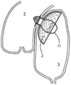
FIG. 11 is a schematic view of an in vivo connector according to the present invention in situ;
FIG. 12 is a schematic view of a flow regulating device according to the present invention during insertion;
FIG. 13 is a schematic view of a system according to the present invention in situ;
FIGS. 14 and 15 are schematic illustrations of a first preferred flow adjustment device according to the present invention in an inserted state;
FIG. 16 is a schematic illustration of a second preferred flow adjustment device according to the present invention in an inserted state;
FIG. 17 is a partial schematic view of the compressible flow adjustment device shown in FIG. 15;
FIG. 18 is a schematic view of the compressible flow conditioning device shown in FIG. 16 during insertion;
FIG. 19 is a partial schematic view of the compressible flow adjustment device shown in FIG. 18;
FIG. 20A is a schematic view of a first seal member used in the present invention in a deployed position and two alternative operating positions;
FIG. 20B is a schematic view of a second seal used in the present invention;
21A-21D are top and bottom views of a connector having an anchor portion with multiple arms and a shield in accordance with the present invention;
FIG. 21E is a partial schematic view of a connector according to the present invention;
FIG. 22 is a schematic view of a flow conditioning device including a reverse screw pump according to the present invention;
fig. 23 is a schematic view of the coupling/decoupling apparatus according to the present invention.
Detailed Description
Referring to fig. 1, the percutaneous puncture system 1 as shown, in situ, includes an in vivo connector 2 passing through at least one wall 5, 6 and for fluidly communicating two anatomical compartments 3, 4. In this figure, the first anatomical compartment is the left atrium 3 of the heart, the second anatomical compartment is the aorta 4, the first anatomical wall is the apex 5 of the left atrium 3, and the second wall is the wall 6 of the aorta 4.
The connector 2 is designed to maintain and support structural integrity of the anatomical walls and compartments, which are typically resistant to pressure exerted by flooding, but is also used during insertion, implantation and retrieval of the transcutaneous penetration device.
An in-body connector 2 according to the present invention will be explained below with reference to fig. 1 and fig. 2A to 2C. The connector 2 comprises a waist or neck portion 7, and an anchor portion 8 and a shield 9. Fluid, here blood, may flow through the neck 7 through the portal 10. The connector 2 is made of one or more biocompatible materials and may be left in the patient after treatment is completed, as desired.
Typically, the neck 7 is made of a semi-flexible to substantially rigid material, whereby pressure from the surrounding tissue does not compress the neck 7 and impede fluid flow. The neck 7 comprises a biocompatible or surgical material, for example a metal or a plastic material. The doorway 10 is made of an elastic material (e.g., a plastic material or a shape memory material) and thus may be in an s-open position to allow fluid flow or a closed position to prevent fluid flow. The neck 7 may comprise a solid surface as shown in fig. 1-3, or may be comprised of a mesh-shaped surface as shown in fig. 21E.
With the actuator stationary, the doorway 10 is maintained in a closed position. Two examples of doorways 10 are shown in figures 3A and 3B. In fig. 3A, doorway 10 is comprised of several sections that can fit together in a closed position and be pushed apart to form an opening. In fig. 3B, doorway 10 includes an opening 10A that prevents blood flow in the closed position, but may be stretched to the open position to allow blood flow.
In this embodiment, the system 1 connects the left atrium 3 to the aorta 4, the left atrium 3 and the aorta 4 being relatively close to each other. However, the shape and size of the neck 7 can be adjusted when the compartments are located at different or distant locations. For example, the neck 7 may be made sufficiently flexible to bend into place or set to hinge.
An anchor portion 8 extends from a first end of the neck portion 7. The anchor portion 8 is made of an elastic material, such as a shape memory material, whereby it can be embedded in a contracted state (as shown in fig. 10A and 10B) and mounted in an expanded state (as shown in fig. 1 and 2). In its contracted state, the anchor portion 8 is substantially cylindrical. In its deployed state, the anchor portion 8 may be arranged to prevent the connector 2 from moving within the anatomical wall 5, 6 or from moving out of the anatomical wall 5, 6. In this embodiment, the anchor portion 8 in the deployed state is attached to and extends substantially perpendicularly from the end of the neck portion 7, whereby it abuts and/or is substantially parallel to the anatomical wall, i.e. the aortic wall 6.
A shield 9 extends from the second end of the neck 7. The shield 9 is made of an elastic material, for example a shape memory material, whereby it can be embedded in a contracted state (as shown in fig. 10A and 10B) and mounted in an expanded state (as shown in fig. 1 and 2). The shield 9 comprises a mesh or grid-like material and may be made of the same or a different material than the anchor 8. In its retracted state, the shield 9 is substantially cylindrical. In its deployed state, the shield 9 may be arranged to prevent surrounding tissue from being suction punctured through the anatomical walls 5, 6. The shield 9 is spread apart so that the surrounding tissue does not contact the shield. This minimizes the risk of damage caused by suction or friction shielding through the mesh. In this embodiment the shield 9 is unfolded substantially in the shape of a bowl or an umbrella.
In fig. 1-3, the anchor 8 is disc-shaped and the shield is bowl-shaped. Both made of a mesh material. In another or alternative embodiment, the connector 2 includes a plurality of arms that extend from one or both ends of the connector 2 to form the anchor 8 and/or the shield 9. The plurality of arms may be curved and/or include one or more elbows, and may be deployable/non-deployable. The plurality of arms may extend along the inner surface of the neck 7 to form a tightening means for securing the flow adjustment device 11 to the connector 2. Examples of such connectors are shown in fig. 21A to 21E.
The flow regulating device 11 according to the present invention will be explained below with reference to fig. 4 and 5.
The device 11 includes a distal portion 11A, an intermediate portion 11B, and a proximal portion 11C. In use, the distal end or tip of the distal portion 11A extends into one anatomical compartment 4 and the proximal end or tip of the proximal portion 11C extends into a second anatomical compartment. The intermediate portion 11B is located partially or entirely within the neck portion 7 of the connector 2. Within the scope of the present invention, the term "distal" refers to the position closest to the patient in the insertion direction and the term "proximal" refers to the position closest to the medical staff in this direction. In other words, the distal end of the device is inserted first, and the proximal end of the device is inserted last.
The device 11 includes a channel (not shown) for the passage of blood from the proximal end 11C of the device 11 through its distal end 11A. The proximal end includes one or more openings 12 to allow blood to flow into the device 11 and the distal end includes one or more openings 13 to allow blood to flow out of the device 11. The distal end of the device 11 is rounded to minimize trauma and protrudes in a pointed shape to make insertion easier.
The flow adjustment device 11 includes a means of fixing the device 11 to the connector 2, and an example of such a fixing means is shown in fig. 5A to 5B. In fig. 5A, the distal end of the device 11 includes one or more ribs 14 or protrusions that serve to prevent the device 11 from moving against the flow of fluid. In fig. 5B, part or all of the intermediate portion 11B is made of a resilient or expandable material that holds the device 11 in place. A better grip may be provided to the inner surface of the neck of the connector by modifying the outer surface of the intermediate portion 11B. In fig. 5C, the distal end 11A of the device 11 includes a flap 15 or protrusion that can be deployed to prevent the device 11 from moving against the flow of fluid or can be retracted during insertion.
Another example of a fixture is presented through doorway 10. During insertion, the distal end of the device 11 is pushed through and opens the doorway 10, and, in the insertion position, the intermediate portion 11B is located partially or entirely within the neck portion 7 of the connector 2, passing through the doorway 10. Thus, the gateway material elastically closes around the distal end 11A of the device 11 and secures the device 11 to the connector 2. According to the insertion procedure of the present invention, the distal portion 11A of the device 11, or the distal end of the distal portion 11A, acts as an actuator for the connector 2 by opening the doorway 10 and allowing blood to flow from the left atrium to the aorta.
Alternatively or additionally, the connector 2 and the flow adjustment device 11 may comprise complementary securing means, such as tightening means, located on the inner surface of the neck portion 7 of the connector 2 and the outer surface of the intermediate portion 11B of the flow adjustment device 11. The advantage of the tightening device is in particular that the flow adjustment device can be (detachably) fixed to the connector, but can also be used to assist in advancing and positioning the flow adjustment device through the connector.
In another preferred embodiment, the connector 2 and the flow adjustment device 11 may be connected by a twist lock mechanism, an example of which is shown in FIG. 21E. In this embodiment, the neck 7 may comprise two or more channels or longitudinal protrusions for locking.
The connector 2 may also include sealing means for preventing unwanted fluid flow or securing means at the coupling interface of the connector and the flow regulating means. For example, the connector and flow conditioning device include a complementary tightening device, and the sealing device includes a strip of sealing material that mirrors the screw profile of the tightening device. Thereby, in use, the sealing means is sandwiched between the tightening means of the connector and the tightening means of the flow adjustment device.
The deployable sealing means used, in its deployed state, are substantially in the form of a rectangular strip of sealing material. In its contracted state, the sealing device is substantially helical. The sealing means may be made of a flexible material and/or a shape memory material. The sealing means may comprise fixing means for fixing the sealing means to the connector and/or flow regulating means.
The flow regulating device 11 includes a channel 34 through which channel 34 receives the wire 19 b. In a preferred embodiment, the channel 34 extends from the proximal end to the distal end of the flow adjustment device 11. Preferably, the channel 34 extends along a central longitudinal axis of the flow conditioning device 11.
The flow regulating device 11 comprises an internal pump 16. The pumping parameters are adjusted by an in-vivo or in-vitro controller (not shown). If an external controller is used, a wireless controller is preferred. Current may be supplied to the pump 16 via electrical leads 17 or the device 11 may include an internal battery. If a rechargeable battery is used, it is preferred that no charging mechanism, e.g., a magnetic charging mechanism, of the device inserted into the patient is required. If a non-rechargeable battery is used, the device 11 may be removed and replaced or discarded after use. The electrical lead 17 or other conduit may be used as a pull cord to remove the device 11 from the patient after use or a special pull cord may be attached.
If the fluid pumped from compartment 3 requires treatment or treatment before it is delivered to compartment 4, a suitable device (not shown) may be incorporated into device 11. For example, a drug delivery device may contact blood with one or more drugs via device 11; or may utilize an oxygen supply device or membrane to oxygenate the blood prior to its exiting the device 11. In the case of drug administration, the device 11 is integrated with the drug container or the device 11 is connected to an external drug container. A slow release or controlled release mechanism may also be designed. The system 1 according to the invention can also be regarded as an in vivo drug delivery system with or without blood flow, wherein a drug is delivered into the target compartment.
The flow regulating device 11 is self-contained and therefore all elements, including the pump 16, the administration or oxygenation device, may be incorporated into the housing of the flow regulating device 11 as desired.
The preferred flow conditioning device 11 for use in the present invention is described below in connection with fig. 16-19. This device 11 is a variation of the apparatus described above and may include any of the features described above with respect to the device 11.
The flow regulating device 11 includes a distal end portion 11A, an intermediate portion 11B, and a proximal end portion 11C. Proximal portion 11C forms a housing that partially or completely encloses pump 16. Proximal portion 11C also includes a removable base 11D. The base 11D may be attached by rotation, for example by a screw or bayonet arrangement. This removable base 11D includes one or more openings 27 so that fluid can flow from the first anatomical compartment into the base opening 27, through the device 11, and out the opening 13 at the distal end 11A of the device 11 into the second anatomical compartment.
The base 11D includes a rotatable shaft 16A that supports at least one blade 16B. The blade 16B is a spiral blade extending from the shaft 16A. The proximal end of the blade may extend from the shaft 16A. The distal end of the blade 16B may/may not be attached to the distal end of the proximal portion 11C of the device 11 or the proximal end of the intermediate portion 11B of the device 11. The helical blade 16B is provided and constructed so that it can be extended or stretched in the longitudinal direction of the shaft 16A to make it easy to insert the working sheath 21. In the extended configuration, the rotating blades 16B are longitudinally stretched such that the overall diameter of the blades 16B is smaller than its diameter in the relaxed configuration. As the blade 16B passes out of the sheath 21, the blade 16B returns to its initial relaxed configuration, i.e.: in its operating configuration. In this operating configuration, the overall diameter of the blade 16B is greater than its diameter in the extended configuration. Thus, when the helical blade 16B is in the extended configuration, the blade 16B can easily pass through the sheath 21, whereas in the working configuration, the size of the blade 16B is maximized for optimum energy efficiency. This also means that it is possible to use blades 16B having a greater number of turns of the helix to form a unit length (and thus more efficient). Any part of the device 11, in particular the proximal portion 11C and/or the blades 16B of the device 11, may be made of an elastic (or shape memory) material, which may be the same or different. In a preferred embodiment, the extendable pump is surrounded by the proximal portion 11C of the device 11, and the proximal portion 11C is made of a resilient material so that it can be compressed to fit within a sheath and then deployed for use. In this embodiment, the base 11D is preferably made of a rigid material.
In another embodiment as shown in fig. 22, the flow adjustment device 11 comprises a reverse threaded pump mechanism with threads and/or vanes 33 disposed on a rotatable inner surface of the flow adjustment device 11 such that fluid is drawn from a first compartment into a second compartment. In this embodiment, blood flows centrally within the flow regulating device. This arrangement also has the advantage that the wires can be easily placed along the central longitudinal axis of the flow conditioning device 11.
The use of deployable percutaneous penetration components (e.g., expandable connectors and flow regulating devices) is intended to meet the demands of miniaturization. In other words, a full-size component may be inserted through a small incision into a patient's vascular system in a collapsed or compressed state, deployed at the correct site and subsequently removed from the patient's body in the collapsed or compressed state without having to reduce the size of the component (thereby resulting in reduced energy efficiency). This provides a more versatile system in terms of size and shape from which especially children would benefit greatly. This also means that not only the subcutaneous drive train can be used, but also the external drive train and the deployable components can be used to traverse the venous system. Thus, if the aorta can be avoided, the risk of infection and major bleeding is greatly reduced.
A percutaneous insertion device 18 in accordance with the present invention will be described below in connection with fig. 6-8.
The percutaneous insertion device 18 includes a puncture tip 19a integral with a lead 19b and a dilator 19 c. The insertion device further comprises a working sheath 21 and an outer sheath 23. Any equipment or components required for the method according to the invention are inserted using the insertion means 18. As described in more detail below, the needle 19, and in particular the piercing head 19a, is used to pierce one or more anatomical walls; the wire 19 is used to guide the component during insertion; the dilator 19c is used for stretching the puncture hole formed by the puncture head 19 a; the working sheath 21 is used to insert, transport and position the devices of the system 1; and the outer sheath 23 is used to form a safe channel for inserting devices of the system 1.
In this embodiment, the puncture tip 19a is attached, such as by welding, to the distal end of the lead 19 b. The piercing head 19a has a solid tip, i.e., no hollow passage for a standard insertion needle or injection needle. The piercing head 19a is conical and forms a very sharp tip. The diameter of the bottom of the conical piercing tip 19a is larger than the diameter of the lead 19 b. The lead wire 19b slidably passes through the dilator 19 c. The diameter of the base of the conical piercing head 19a is substantially equal to the diameter of the distal end of the dilator 19c to form a flush, smooth transition.
In another embodiment (not shown), the diameter of the bottom of the conical piercing tip 19a is substantially equal to the diameter of the wire 19b, such that the wire 19b is a tapered wire having a sharp tapered tip. In this embodiment, the piercing head 19a and the lead 19b are formed as a single piece. The diameter of the guidewire 19b is substantially equal to the diameter of the distal end of the dilator to form a flush, smooth transition; however, the dilator 19c may not be required when the tapered wire 19b acts as a needle.
The use of a sharp piercing tip 19a at the distal end of the lead 19b makes the insertion device 18 a non-invasive and accurate piercing device. The relative sizes of the puncture tip 19a, the lead 19b and the dilator 19c provide a gradual gentle enlargement of the puncture.
Preferably, the lead 19b includes two or three sections of different stiffness, e.g., a more stiff distal section of material, a flexible intermediate section of material, and a more stiff proximal section of material. The difference in rigidity makes it possible to manipulate and guide a guide wire through the patient.
Referring to fig. 7D, the lead 19a includes at least two sections having different rigidities, namely: the more rigid proximal portion of material is used to guide and push the piercing head 19a through the patient's body, and the more flexible distal portion of material. The flexible portion is particularly advantageous in preventing injury within the patient's body, for example, when advancing the guide wire 19b or inserting and positioning an intracorporeal device. For example, the flexible portion may be looped around the piercing head 19a to protect surrounding tissue and prevent accidental movement of the piercing head 19 a.
As described in more detail below, the insertion component 18 makes it possible to create a secure path for inserting, installing, and removing various components of the system 1. More specifically, the insertion device 18 according to the invention is particularly advantageous for the penetration of anatomical walls, for example of the outer walls of anatomical compartments having a greater resistance to tissue. The insertion device 18 makes it possible to create very precise and small wounds, which is very important for wounds involving high pressure blood flow. One preferred use of insertion member 18 is for external wall piercing of an organ within the body, such as external heart piercing.
The method according to the invention will be explained below in connection with the example of a left atrial-aortic junction.
The first step is to insert the wire, which can be accomplished by techniques known in the art. The needle with the guide wire is placed in the groin area of the patient, adjacent to the femoral artery. Pressure is applied to cause the needle tip to pierce the patient's skin and pass through the skin and tissue into the femoral artery. Once in place, the guide wire is advanced along the femoral artery and ascends into the inferior vena cava 25. Referring to fig. 9, the lead is in the inferior vena cava 25 and enters the right atrium 26. Septum puncture between the left atrium and the right atrium can be performed by prior art techniques. The lead is now extended from outside the patient's body through a skin puncture into the femoral artery, inferior vena cava 25, right atrium 26, atrial septum and left atrium 3, preferably temporarily attached to the left superior pulmonary vein. A large steerable support sheath may then be placed into the left atrium over the guide wire to facilitate the final steps in the overall procedure. Skin and/or septum punctures may be equally performed using the insertion device 18 of the present invention, although the insertion device 18 is most advantageous when performing an extracardiac puncture as described below.
The second step is to insert and install the insertion device 18 of the present invention. Preferably, the needle 19 is advanced through the groin and along the route described above by means of dedicated sheaths 21 and 23. The lead 19b includes a relatively flexible distal portion adjacent the puncture head and forward of a relatively rigid proximal portion such that the flexible portion of the lead 19b folds upon itself to form a U-shape. The flexible portion is preceded by a rigid proximal portion. Thus, the lead 19b may be atraumatically passed through a delivery sheath or through a patient's blood vessel. If desired, the lead 19b can be straightened by pulling slightly on the proximal end and repositioning the distal end portion at its forwardmost end. The piercing head 19a is pulled towards the distal end of the dilator 19 c.
The third step is to perform an extracardiac puncture of the left atrium using the insertion device 18 of the present invention. The distal end of the outer sheath 23 abuts the tip of the left atrium 3 and is pushed against the wall so that the tip of the left atrium 3 contacts the aortic wall. The puncture head is advanced to form a puncture in the top of the left atrium 3. This sharp conical shape enables medical personnel to form small and precise extra-cardiac incisions in a smooth, atraumatic manner. The puncture head 19a and dilator 19c are advanced through the puncture towards the aortic wall. The outer sheath 23 is used to push the wall of the left atrium against the aortic wall and to control the two walls together to assist in the puncture of the aortic wall. Once the aortic wall is pierced, the dilator 20 can distract the two punctures to facilitate insertion of the working sheath 21. The dilator 19c may be removed leaving and positioning the guide wire 19b and working sheath 21 within the aorta 4. The outer sheath 23 may remain within the left atrium 3.
The puncture head 19a is advanced further into the aorta 4. As the dilator 19c is withdrawn, the flexible portion of the guidewire 19b will coil around the puncture tip 19a, thereby anchoring and shielding the puncture tip 19a from the surrounding tissue. Additionally or alternatively, a receiving catheter may be placed inside the aorta 4 by known techniques for receiving and protecting the puncture tip 19a within the aorta.
Thus, it will be appreciated that the support sheath 23 may be used to safely transport an in-vivo device but also to assist in the penetration of anatomical walls, particularly methods involving the penetration of more than one anatomical wall.
The fourth step is to insert the in-body connector 2 according to the present invention. Referring to fig. 10A and 10B, the in vivo connector 2 in a folded or compressed state is inserted along the working sheath 21 of the lead 19B. When the connector 2 reaches the top of the left atrium, it is pushed along the guide wire 19b through the incision in the anatomical walls 5, 6 until the neck 7 is correctly placed between the anatomical walls 5, 6 and the anchor 8 and the shield 9 are deployed inside the aorta 4 and left atrium 3 on both sides of the walls 5, 6, respectively (fig. 11). As the connector 2 moves away from the distal end of the working sheath 21, the connector 2 gradually deploys.
The fifth step is the insertion of an in vivo flow modulation device 11, as shown in figure 4 or figure 15 of the present invention. Referring to fig. 12, body flow modulation device 11 is inserted and advanced through sheath 21 along guidewire 19b until it reaches connector 2. The distal end portion 11A, in particular the distal tip of the connector 2, acts as an actuator to open the gateway 10 of the neck 7 of the connector 2 by stretching the opening 10A of the gateway 10. The intermediate portion 11B of the flow regulating device 11 is located in the neck portion 7 of the connector 2 and is securely positioned. The flow regulating device 11 can be fixed by the pressure of the elastic material of the doorway 10 and the rib 14. Additionally or alternatively, the flow may secure the flow conditioning device 11 by screwing the intermediate portion 11B of the flow conditioning device 11 to the neck portion 7 of the connector 2. This tightening mechanism also enables the flow adjustment device 11 to be safely guided to the interior of the connector 2. Where a sealing means is provided, the sealing means prevents any leakage through the coupling interface between the flow adjustment device 11 and the connector 2. Unless further required, the working sheath 21 can now be removed.
Thus, it will be appreciated that the insertion device 18 according to the present invention provides a dual purpose. First, the piercing head 19 can be used to pierce the anatomical wall in a safe, controlled and atraumatic manner. Second, the insertion device 18 may be used as an integrated lead 19 b. Thus, there is no need to use a needle and a separate wire in two separate steps. This reduces the risk of accidents and simplifies the insertion procedure.
As shown in fig. 16-19 for a compressible/expandable flow adjustment device, the base 11D of the device 11 is separated from the proximal end portion 11C and the blades 16B are stretched to their deployed positions. For example, the base 11D is rotated or not tightened, so simultaneously, the base 11D separates from the proximal end portion 11C and the blade 16B extends. The device 11 is advanced into the distal end of the sheath 21 and the distal end 11A of the device 11 is properly positioned ready to activate the portal 10. The base 11D is reattached to the proximal end 11C of the device 11, for example by rotating the cinching device, whereby the blade 16B relaxes into the operative configuration. The distal end 11A of the flow regulating device 11 can now be pushed through the doorway 10 to allow fluid flow.
The insertion and installation method described above may be facilitated by visualization techniques, such as X-ray, fluoroscopy, echocardiography, ultrasound techniques.
The pump 16 is activated to regulate blood flow between the left atrium 3 and the aorta 4. Blood flows from the left atrium 3 into the proximal end of the device 11, through the device and into the aorta 4 from an aperture 13 at the distal end of the device 11.
Blood flow, timing of blood flow, temperature, and other parameters may be controlled and adjusted. Similarly, as blood flows through the device 11, drugs and/or oxygen may be added and/or contaminants may be removed from the blood. As blood is drawn into the device 11, the surrounding tissue is prevented from obstructing the blood passage by the shield 9. Blood flow has a tendency to push the device 11 back into the left atrium, but the fixation device as described above immobilizes the device 11.
When the treatment is complete, the flow regulating device 11 may be removed from the patient's body if a recharging service or replacement is required. The sheaths 21, 23 are inserted through the patient and a dedicated coupling/decoupling device 35 is used, which includes a means for coupling the flow regulating device 11. The coupling/decoupling device is attached to the flow conditioning device 11, such as by one or more engagement tabs 36a engaging corresponding recesses 36b in the flow conditioning device 11. The attachment means is remotely steerable. The coupling/decoupling means comprises a rotation means for unscrewing the flow regulating means 11 from the connector 2 and the flow regulating means 11 can be safely retrieved through the sheaths 21, 23. The coupling/decoupling device may also be used in an insertion process to advance the flow adjustment device 11 through the sheaths 21, 23 and to screw the flow adjustment device 11 to the connector 2.
After removal of the device 11, the door 11 is closed and blood flow is halted and the connector 2 is left in place or removed.
Although the present invention as described above is directed to a left atrial-to-aorta procedure, the systems and methods may also be used for other delivery points including, but not limited to, the right atrium-aorta, the vena cava-pulmonary artery, and the vena cava-aorta. Thus, the invention can be used broadly as, for example, a left heart assist device (LVAD), a right heart assist device (RVAD), or a BiVAD for cardiopulmonary support (CPS), or for in vivo membrane oxygenation (ICMO) or bubbleoxygenation, or for the treatment of other organs with pressure problems (e.g., gastric or neurological treatments). The present invention is versatile and therefore widely applicable.
From the foregoing, it will be appreciated that the present invention constitutes a new alternative to existing percutaneous procedures. The percutaneous puncture procedure of the present invention requires limited machinery and equipment, providing a simple, safer, and less expensive alternative to existing procedures. All components are inserted and implanted percutaneously, so invasive open surgery is not always required. Furthermore, the device described herein can be easily used for pediatric treatment.
It is important to note that the present invention relies on artificially created fluid channels. Cardiopulmonary or circulatory collapse and heart failure can result from a variety of acquired or congenital conditions and can affect different anatomical regions of the heart and circulatory system and respiratory system. Existing treatment procedures often seek to repair or replace defective anatomical sites. The present invention provides a more inclusive treatment procedure as it relies on manually created channels that bypass defective portions of the circulatory system and allows for the use of new treatment concepts and techniques compared to current treatment methods.
However, the present invention is designed to be used in the following cases: insufficient, defective or uncontrolled fluid flow through natural pathways, and the necessity to restore pathways or fluid flow. For example, the condition is severe pulmonary valve stenosis, severe aortic valve stenosis, atresia, or severe mitral valve stenosis.
By using an insertion device that includes the above-described lead and an integrated piercing head, the present invention allows for safe and atraumatic penetration of structurally sensitive anatomical walls. The present invention allows for the safe implantation, positioning and operation of flow regulating devices using connectors as described above, which provides structurally sensitive anatomical wall integrity. The present invention allows for the treatment of patients who may have anatomical defects that do not receive conventional treatment. The invention is applicable to smaller patients, such as children, or where it is not possible to use or introduce large instruments. The present invention provides minimally invasive treatment that does not affect the post-operative mobility of the patient.
The system has a safe, stable, predictable structure that allows improved therapeutic devices to be transferred from one compartment to another through a shorter and more beneficial route.
Further aspects of the invention can be found in the following paragraphs.
1. The percutaneous system includes an in vivo connector for fluid communication of two anatomical compartments through at least one anatomical wall.
2. The system according to paragraph 1, wherein the connector comprises a neck providing fluid passage from one compartment to another and means for securing the neck across the anatomical wall.
3. The system of paragraph 2, wherein the fixation device includes an expandable anchor extending from a first end of the neck.
4. The system of paragraph 3, wherein the anchor portion is positioned substantially parallel to the anatomical wall in its expanded state.
5. The system of any of paragraphs 2-4, wherein the connector comprises a prevention device to prevent tissue from obstructing the fluid pathway through the neck.
6. The system of paragraph 5, wherein the prevention means comprises an expandable shield extending from the second end of the neck.
7. The system of paragraph 6, wherein the shield in its expanded state does not substantially contact the anatomical wall.
8. The system of any preceding paragraph, wherein the connector is made entirely or partially of a shape memory material.
9. The system of any of paragraphs 2-8, wherein the neck comprises a gate that selectively prevents or allows fluid passage through the neck.
10. The system according to any of the preceding paragraphs, further comprising an in vivo flow regulating device for regulating fluid flow between the two anatomical compartments.
11. The system according to paragraph 10, wherein the flow regulating device comprises an actuator for allowing or preventing fluid flow through the connector in the body.
12. The system according to paragraph 11 or 12, wherein the flow regulating device comprises a pump.
13. The system of any preceding paragraph, further comprising a fluid treatment device for treating the fluid.
14. The system according to paragraph 13, wherein the fluid handling device comprises a device for contacting the fluid with one or more pharmaceutical compounds.
15. The system according to paragraph 13 or 14, wherein the fluid treatment means comprises means for contacting the fluid with one or more gases, such as oxygen.
16. The system of any of paragraphs 10-15, further comprising means for securing the flow regulating device to the connector.
17. The system of any of paragraphs 10-16, wherein the flow regulating device comprises a selectively rotatable shaft supporting at least one vane adapted to extend in a length direction of the shaft into the insertion configuration.
18. The system of paragraph 17, wherein the blade is adapted to relax into the operating configuration in a direction of the length of the shaft.
19. The system according to section 18, wherein the dimension of the blade in the transverse direction of the shaft is greater in the working configuration than in the insertion configuration.
20. The system of any of the paragraphs 17-19, wherein the blade is a helical blade.
21. The system of any of the paragraphs 17-20 wherein the blade is made of a length of resilient material.
22. The system according to any of the preceding paragraphs, wherein one or both anatomical compartments are compartments of the circulatory system.
23. The system according to any preceding paragraph, wherein the fluid is blood.
24. The system according to any preceding paragraph, wherein the system is a ventricular assist device.
25. The system of any of the preceding paragraphs, further comprising a percutaneous insertion device having a needle comprising a needle body, a guidewire, and a puncture head.
26. The system of paragraph 25, wherein the piercing head comprises a solid tip.
27. The system of paragraph 25 or 26, wherein the widest cross-section of the penetration head has dimensions substantially equal to the dimensions of the cross-section of the distal end of the lead.
28. The system of any of paragraphs 25-27, wherein the insertion device further comprises a dilator.
29. The system of paragraph 28, wherein the size of the widest cross-section of the puncture head is substantially equal to the size of the cross-section of the distal end of the dilator.
30. The system of any of paragraphs 25-29, wherein the insertion device further comprises a means for guiding a sheath.
31. An in vivo connector as described in any preceding paragraph.
32. An in vivo flow modulation device as described in any of paragraphs 10-21.
33. A percutaneous insertion device as in any of the paragraphs 25-30.
34. A percutaneous method for providing fluid communication between two anatomical compartments, the method comprising the steps of: piercing the wall separating the compartments, and inserting an in vivo connector through the pierced hole between the two compartments.
35. The method of paragraph 34, wherein the piercing step is performed using an insertion device as described in any of paragraphs 25-30.
36. The method of paragraph 34 or 35, wherein the in vivo connector is a connector as described in any of paragraphs 1-30.
37. The method of any of paragraphs 34-36, further comprising the step of regulating fluid flow between the two anatomical compartments.
38. The method of paragraph 37, regulating the fluid flow using an in vivo flow regulation device as described in any of paragraphs 10-30.
39. The method of any of paragraphs 34-38, further comprising the step of treating the fluid.
40. The method of paragraph 38, wherein the treatment fluid is carried out using a treatment device as set forth in any of paragraphs 13-15.
41. The method of any of paragraphs 34-40, wherein one or both compartments are compartments of a circulatory system.
Claims (54)
1. A transcatheter system comprising an in vivo connector for fluid communication between two anatomical compartments through at least one anatomical wall, wherein the connector is adapted to receive a flow modulation device,
it is characterized in that the preparation method is characterized in that,
the connector comprises a neck adapted for fluid passage from a first compartment to a second compartment, and the connector comprises a prevention means to prevent tissue from obstructing the fluid passage through the neck, wherein the prevention means comprises an expandable shield extending from a first end of the neck.
2. The system of claim 1, wherein the prevention device comprises a plurality of arms extending from the first end of the neck.
3. The system of claim 1, wherein fluid is flowable from the first compartment to the second compartment when the flow regulating device is coupled to the connector and is not flowable from the first compartment to the second compartment when the flow regulating device is not coupled to the connector.
4. The system of claim 1, further comprising a securing device that removably secures the flow adjustment device to the connector.
5. The system of claim 4, wherein the connector and flow adjustment device comprise cooperating tightening devices.
6. The system of claim 4, further comprising a device that encloses the fixation device.
7. The system of claim 1, wherein the neck is configured to removably secure a flow adjustment device to the connector.
8. The system of claim 1, further comprising a stabilizing device that traverses the neck across the anatomical wall.
9. The system of claim 8, wherein the stabilizing device includes an expandable anchor extending from the second end of the neck.
10. The system of claim 9, wherein the anchor portion in its expanded state is positioned substantially parallel to an anatomical wall of the second compartment.
11. The system of claim 9, wherein the anchor portion comprises a plurality of arms extending from the second end of the neck portion.
12. The system of any preceding claim, wherein the connector further comprises a door that selectively prevents or allows fluid passage from the first compartment to the second compartment.
13. The system of claim 12, wherein the gate is located at the neck of the connector.
14. The system of claim 12, wherein the gate can allow fluid passage when the flow regulating device is received through the gate and prevent fluid passage when the flow regulating device is absent.
15. The system of claim 1, wherein the connector is collapsible.
16. The system of claim 1, wherein the connector is made in whole or in part of a shape memory material.
17. The system of claim 1, the flow regulating device comprising an in vivo flow regulating device adapted to regulate fluid flow between the two anatomical compartments.
18. The system of claim 17, wherein the in vivo flow modulation device comprises an actuator that allows or prevents fluid flow through the in vivo connector.
19. The system of claim 17 or 18, wherein the in vivo flow modulation device comprises a first portion in use located in the first compartment, a second portion in use located in the second compartment, and an intermediate portion in use passing through the anatomical wall.
20. The system of claim 19, wherein the intermediate portion passes through and is secured to a neck portion of the connector in use.
21. The system of claim 20, wherein the intermediate portion passes through a door of the connector.
22. The system of claim 19, wherein the intermediate portion comprises a channel adapted for fluid communication between the first compartment and the second compartment.
23. The system of claim 19, wherein fluid is flowable from the first compartment to the second compartment when the connector is coupled to the intermediate portion of the body flow modulation device, and fluid is not flowable from the first compartment to the second compartment when the connector is not coupled to the intermediate portion of the body flow modulation device.
24. The system of claim 19, wherein the in vivo flow modulation device comprises a pump.
25. The system of claim 24, wherein the pump is located within the first portion of the body flow modulation device.
26. The system of claim 24 or 25, wherein the pump comprises a rotating shaft supporting at least one blade configured to extend longitudinally of the shaft into an insertion configuration.
27. The system of claim 26, wherein the blade is configured to relax into an operational configuration along a longitudinal direction of the shaft.
28. The system of claim 27, wherein the blade has a greater dimension in a transverse direction of the shaft in the operating configuration than in the insertion configuration.
29. The system of claim 26, wherein the blade is a helical blade.
30. The system of claim 26, wherein the blade is made of a longitudinally elastic material.
31. The system of claim 24 or 25, wherein the pump comprises a reverse screw pump device.
32. The system of claim 17, wherein the in vivo flow modulation device comprises a fluid treatment device.
33. The system of claim 32, wherein the fluid treatment device comprises a device that contacts the fluid with one or more pharmaceutical compounds.
34. A system according to claim 32 or 33, wherein the fluid treatment device comprises means for contacting the fluid with one or more gases.
35. The system of claim 34, wherein the gas comprises oxygen.
36. The system of claim 19, wherein the first portion and/or the second portion comprises one or more apertures for fluid passage from the first compartment to the second compartment.
37. The system of claim 19, wherein the in vivo flow modulation device comprises a means for securing the in vivo flow modulation device to the connector.
38. The system of claim 37, wherein the second portion of the body flow modulation device includes one or more flanges for abutting the anatomical wall or the expandable anchor portion of the connector.
39. The system of claim 19, wherein the intermediate portion is made of an expandable material.
40. The system of claim 19, wherein the first portion has a cross-section with a diameter greater than a diameter of a cross-section of the intermediate portion.
41. The system of claim 19, wherein the second portion is substantially conical.
42. The system of claim 19, wherein the second portion has a rounded distal tip.
43. The system of claim 19, wherein the in vivo flow modulation device is configured to receive a guidewire therethrough.
44. The system of claim 43, wherein the first portion, the second portion, and/or the intermediate portion includes an aperture to receive a lead therethrough.
45. The system of claim 43 or 44, wherein the in vivo flow modulation device is configured to receive a guide wire along a longitudinal axis.
46. The system of claim 17, wherein all or a portion of the in vivo flow modulation device is collapsible.
47. The system of claim 1, wherein one or both of the two anatomical compartments are compartments of the circulatory system.
48. The system of claim 1, wherein the fluid is blood.
49. The system of claim 1, which is a ventricular assist device.
50. The system of claim 1, wherein the anatomical compartments are separated by two anatomical walls.
51. The system of claim 1, wherein the two anatomical compartments are not anatomically adjacent.
52. The system of claim 1, wherein the connector and the flow regulating device are constructed as one device.
53. An in vivo connector for fluid communication of two anatomical compartments through at least one anatomical wall, wherein the connector is adapted to receive a flow regulating device,
it is characterized in that the preparation method is characterized in that,
the connector comprises a neck adapted for fluid passage from a first compartment to a second compartment, and the connector comprises a prevention means to prevent tissue from obstructing the fluid passage through the neck, wherein the prevention means comprises an expandable shield extending from a first end of the neck.
54. A transcatheter system according to any one of claims 1-52 for use in treating heart failure, pediatric cardiac abnormality, and/or bypass.
Priority Applications (1)
| Application Number | Priority Date | Filing Date | Title |
|---|---|---|---|
| CN202010176604.7A CN111493985A (en) | 2014-03-17 | 2015-03-17 | Percutaneous systems, devices and methods |
Applications Claiming Priority (5)
| Application Number | Priority Date | Filing Date | Title |
|---|---|---|---|
| NO20140353 | 2014-03-17 | ||
| NO20140353 | 2014-03-17 | ||
| GB1410320.4A GB2527075A (en) | 2014-03-17 | 2014-06-10 | Percutaneous system, devices and methods |
| GB1410320.4 | 2014-06-10 | ||
| PCT/EP2015/055578 WO2015140179A2 (en) | 2014-03-17 | 2015-03-17 | Percutaneous system, devices and methods |
Related Child Applications (1)
| Application Number | Title | Priority Date | Filing Date |
|---|---|---|---|
| CN202010176604.7A Division CN111493985A (en) | 2014-03-17 | 2015-03-17 | Percutaneous systems, devices and methods |
Publications (2)
| Publication Number | Publication Date |
|---|---|
| CN106456855A CN106456855A (en) | 2017-02-22 |
| CN106456855B true CN106456855B (en) | 2020-04-10 |
Family
ID=52697402
Family Applications (2)
| Application Number | Title | Priority Date | Filing Date |
|---|---|---|---|
| CN201580004854.XA Active CN106456855B (en) | 2014-03-17 | 2015-03-17 | Percutaneous systems, devices and methods |
| CN202010176604.7A Pending CN111493985A (en) | 2014-03-17 | 2015-03-17 | Percutaneous systems, devices and methods |
Family Applications After (1)
| Application Number | Title | Priority Date | Filing Date |
|---|---|---|---|
| CN202010176604.7A Pending CN111493985A (en) | 2014-03-17 | 2015-03-17 | Percutaneous systems, devices and methods |
Country Status (9)
| Country | Link |
|---|---|
| US (5) | US9539378B2 (en) |
| EP (2) | EP3119451B1 (en) |
| JP (2) | JP6638975B2 (en) |
| KR (1) | KR20160135165A (en) |
| CN (2) | CN106456855B (en) |
| AU (2) | AU2015233534B2 (en) |
| CA (1) | CA2936528C (en) |
| GB (1) | GB2527075A (en) |
| WO (1) | WO2015140179A2 (en) |
Families Citing this family (86)
| Publication number | Priority date | Publication date | Assignee | Title |
|---|---|---|---|---|
| GB0419954D0 (en) | 2004-09-08 | 2004-10-13 | Advotek Medical Devices Ltd | System for directing therapy |
| US20100191168A1 (en) | 2009-01-29 | 2010-07-29 | Trustees Of Tufts College | Endovascular cerebrospinal fluid shunt |
| EP2429603B1 (en) | 2009-05-11 | 2019-09-18 | Mayo Foundation For Medical Education And Research | Treating congestive heart failure |
| US8579964B2 (en) | 2010-05-05 | 2013-11-12 | Neovasc Inc. | Transcatheter mitral valve prosthesis |
| US9554897B2 (en) | 2011-04-28 | 2017-01-31 | Neovasc Tiara Inc. | Methods and apparatus for engaging a valve prosthesis with tissue |
| US9308087B2 (en) | 2011-04-28 | 2016-04-12 | Neovasc Tiara Inc. | Sequentially deployed transcatheter mitral valve prosthesis |
| US9345573B2 (en) | 2012-05-30 | 2016-05-24 | Neovasc Tiara Inc. | Methods and apparatus for loading a prosthesis onto a delivery system |
| US9848884B2 (en) * | 2013-01-10 | 2017-12-26 | Empire Technology Development Llc | Diverticula removal clamp |
| CN107432762B (en) | 2013-03-08 | 2021-04-13 | 林弗洛公司 | Methods and systems for providing or maintaining fluid flow through a body passageway |
| US9572665B2 (en) | 2013-04-04 | 2017-02-21 | Neovasc Tiara Inc. | Methods and apparatus for delivering a prosthetic valve to a beating heart |
| US9737696B2 (en) | 2014-01-15 | 2017-08-22 | Tufts Medical Center, Inc. | Endovascular cerebrospinal fluid shunt |
| EP3998100A1 (en) | 2014-01-15 | 2022-05-18 | Tufts Medical Center, Inc. | Endovascular cerebrospinal fluid shunt system |
| GB2527075A (en) | 2014-03-17 | 2015-12-16 | Daassist As | Percutaneous system, devices and methods |
| WO2016070147A1 (en) | 2014-10-31 | 2016-05-06 | Cerevasc, Llc | Methods and systems for treating hydrocephalus |
| US10272230B2 (en) | 2015-10-30 | 2019-04-30 | Cerevasc, Llc | Systems and methods for treating hydrocephalus |
| CN108472148A (en) * | 2015-12-30 | 2018-08-31 | 纽哈特股份公司 | Through catheter insertion system |
| US10893847B2 (en) | 2015-12-30 | 2021-01-19 | Nuheart As | Transcatheter insertion system |
| EP4183372A1 (en) | 2016-01-29 | 2023-05-24 | Neovasc Tiara Inc. | Prosthetic valve for avoiding obstruction of outflow |
| WO2017172738A1 (en) * | 2016-03-30 | 2017-10-05 | Heartware, Inc. | Flanged heart tissue blocker |
| WO2018065610A1 (en) * | 2016-10-07 | 2018-04-12 | Nuheart As | Transcatheter device and system for the delivery of intracorporeal devices |
| US10335528B2 (en) | 2016-10-07 | 2019-07-02 | Nuheart As | Transcatheter method and system for the delivery of intracorporeal devices |
| US10537672B2 (en) | 2016-10-07 | 2020-01-21 | Nuheart As | Transcatheter device and system for the delivery of intracorporeal devices |
| EP3522827A4 (en) * | 2016-10-10 | 2020-07-15 | Cook Medical Technologies LLC | Devices and methods for treating congestive heart failure, ascites, and other disorders relating to excess bodily fluid |
| JP2019535415A (en) | 2016-11-21 | 2019-12-12 | ニオバスク ティアラ インコーポレイテッド | Method and system for rapid retraction of a transcatheter heart valve delivery system |
| JP7142020B2 (en) | 2016-11-22 | 2022-09-26 | シネコー・エルエルシー | A system for introducing a mitral valve therapy device (MVTD) to a mitral valve location |
| FR3059906B1 (en) * | 2016-12-09 | 2020-11-13 | Fineheart | KIT FOR INSTALLING / REMOVING A HEART PUMP |
| US11235137B2 (en) | 2017-02-24 | 2022-02-01 | Tc1 Llc | Minimally invasive methods and devices for ventricular assist device implantation |
| EP3609415B1 (en) | 2017-04-10 | 2023-08-23 | LimFlow GmbH | Devices for treating lower extremity vasculature |
| US10888646B2 (en) | 2017-04-28 | 2021-01-12 | Nuheart As | Ventricular assist device and method |
| JP2020519323A (en) * | 2017-04-28 | 2020-07-02 | ヌハート エーエスNuheart As | Ventricular assist device and method |
| US10537670B2 (en) | 2017-04-28 | 2020-01-21 | Nuheart As | Ventricular assist device and method |
| JP7414529B2 (en) | 2017-06-07 | 2024-01-16 | シファメド・ホールディングス・エルエルシー | Intravascular fluid transfer devices, systems, and methods of use |
| US11666444B2 (en) | 2017-08-03 | 2023-06-06 | The Regents Of The University Of California | Atrial cage for placement, securing and anchoring of atrioventricular valves |
| WO2019055154A2 (en) | 2017-08-06 | 2019-03-21 | Synecor Llc | Systems and methods for transseptal delivery of therapeutic devices of the heart |
| US10856984B2 (en) | 2017-08-25 | 2020-12-08 | Neovasc Tiara Inc. | Sequentially deployed transcatheter mitral valve prosthesis |
| JP7319266B2 (en) | 2017-11-13 | 2023-08-01 | シファメド・ホールディングス・エルエルシー | Intravascular fluid transfer devices, systems and methods of use |
| CN117959583A (en) | 2018-02-01 | 2024-05-03 | 施菲姆德控股有限责任公司 | Intravascular blood pump and methods of use and manufacture |
| WO2019173784A1 (en) | 2018-03-08 | 2019-09-12 | Cerevasc, Llc | Systems and methods for minimally invasive drug delivery to a subarachnoid space |
| WO2019195860A2 (en) | 2018-04-04 | 2019-10-10 | Vdyne, Llc | Devices and methods for anchoring transcatheter heart valve |
| WO2019199948A1 (en) | 2018-04-11 | 2019-10-17 | Vadovations, Inc. | Tissue interface apparatus, systems and methods |
| US11278437B2 (en) | 2018-12-08 | 2022-03-22 | Vdyne, Inc. | Compression capable annular frames for side delivery of transcatheter heart valve replacement |
| US11344413B2 (en) | 2018-09-20 | 2022-05-31 | Vdyne, Inc. | Transcatheter deliverable prosthetic heart valves and methods of delivery |
| US11071627B2 (en) | 2018-10-18 | 2021-07-27 | Vdyne, Inc. | Orthogonally delivered transcatheter heart valve frame for valve in valve prosthesis |
| US10595994B1 (en) | 2018-09-20 | 2020-03-24 | Vdyne, Llc | Side-delivered transcatheter heart valve replacement |
| US10321995B1 (en) | 2018-09-20 | 2019-06-18 | Vdyne, Llc | Orthogonally delivered transcatheter heart valve replacement |
| CA3112353A1 (en) | 2018-10-09 | 2020-04-16 | Limflow Gmbh | Devices and methods for catheter alignment |
| US11109969B2 (en) | 2018-10-22 | 2021-09-07 | Vdyne, Inc. | Guidewire delivery of transcatheter heart valve |
| EP3873552A1 (en) * | 2018-11-02 | 2021-09-08 | W.L. Gore & Associates, Inc. | Implantable ventricular assist devices and methods |
| US11737872B2 (en) | 2018-11-08 | 2023-08-29 | Neovasc Tiara Inc. | Ventricular deployment of a transcatheter mitral valve prosthesis |
| US11951313B2 (en) * | 2018-11-17 | 2024-04-09 | Medtronic, Inc. | VFA delivery systems and methods |
| US11484698B2 (en) * | 2019-07-09 | 2022-11-01 | Boston Scientific Scimed, Inc. | Circulatory support device |
| JP7208395B2 (en) * | 2018-12-19 | 2023-01-18 | ボストン サイエンティフィック サイムド,インコーポレイテッド | Circulatory aid |
| US11253359B2 (en) | 2018-12-20 | 2022-02-22 | Vdyne, Inc. | Proximal tab for side-delivered transcatheter heart valves and methods of delivery |
| CN113473905A (en) | 2018-12-21 | 2021-10-01 | W.L.戈尔及同仁股份有限公司 | Implantable medical device with adjustable blood flow |
| US11185409B2 (en) | 2019-01-26 | 2021-11-30 | Vdyne, Inc. | Collapsible inner flow control component for side-delivered transcatheter heart valve prosthesis |
| US11273032B2 (en) | 2019-01-26 | 2022-03-15 | Vdyne, Inc. | Collapsible inner flow control component for side-deliverable transcatheter heart valve prosthesis |
| US11065438B2 (en) | 2019-02-07 | 2021-07-20 | Synecor Llc | Systems and methods for transseptal delivery of percutaneous ventricular assist devices and other non-guidewire based transvascular therapeutic devices |
| WO2020181154A2 (en) | 2019-03-05 | 2020-09-10 | Vdyne, Inc. | Tricuspid regurgitation control devices for orthogonal transcatheter heart valve prosthesis |
| US11173027B2 (en) | 2019-03-14 | 2021-11-16 | Vdyne, Inc. | Side-deliverable transcatheter prosthetic valves and methods for delivering and anchoring the same |
| US11076956B2 (en) | 2019-03-14 | 2021-08-03 | Vdyne, Inc. | Proximal, distal, and anterior anchoring tabs for side-delivered transcatheter mitral valve prosthesis |
| WO2020206012A1 (en) | 2019-04-01 | 2020-10-08 | Neovasc Tiara Inc. | Controllably deployable prosthetic valve |
| CN113924065A (en) | 2019-04-10 | 2022-01-11 | 内奥瓦斯克迪亚拉公司 | Prosthetic valve with natural blood flow |
| CA3138875A1 (en) | 2019-05-04 | 2020-11-12 | Vdyne, Inc. | Cinch device and method for deployment of a side-delivered prosthetic heart valve in a native annulus |
| CN114025813B (en) | 2019-05-20 | 2024-05-14 | 内奥瓦斯克迪亚拉公司 | Introducer with hemostatic mechanism |
| CN110215547B (en) * | 2019-06-15 | 2021-08-24 | 南阳市中心医院 | Malignant ascites puncture drainage device |
| US20200391016A1 (en) * | 2019-06-17 | 2020-12-17 | NXT Biomedical | Method For Bypassing Defective Portions Of A Heart |
| JP2022537559A (en) | 2019-06-20 | 2022-08-26 | ニオバスク ティアラ インコーポレイテッド | Thin artificial prosthetic mitral valve |
| EP3996797A4 (en) | 2019-07-12 | 2023-08-02 | Shifamed Holdings, LLC | Intravascular blood pumps and methods of manufacture and use |
| WO2021016372A1 (en) | 2019-07-22 | 2021-01-28 | Shifamed Holdings, Llc | Intravascular blood pumps with struts and methods of use and manufacture |
| CN114599316A (en) | 2019-08-20 | 2022-06-07 | 维迪内股份有限公司 | Delivery and retrieval devices and methods for sidedly deliverable transcatheter prosthetic valves |
| US11517737B2 (en) | 2019-08-21 | 2022-12-06 | Boston Scientific Scimed, Inc. | Circulatory support pump centering anchoring and centering device |
| EP4021445A4 (en) | 2019-08-26 | 2023-09-20 | Vdyne, Inc. | Side-deliverable transcatheter prosthetic valves and methods for delivering and anchoring the same |
| US20210077791A1 (en) * | 2019-09-13 | 2021-03-18 | Drexel University | Right ventricle-pulmonary artery/left ventricle-aorta conduit |
| WO2021055963A1 (en) * | 2019-09-20 | 2021-03-25 | W. L. Gore & Associates, Inc. | Implantable cardiac assist devices and methods |
| US11724089B2 (en) | 2019-09-25 | 2023-08-15 | Shifamed Holdings, Llc | Intravascular blood pump systems and methods of use and control thereof |
| CA3153757A1 (en) | 2019-11-01 | 2021-05-06 | Limflow Gmbh | Devices and methods for increasing blood perfusion to a distal extremity |
| WO2021101622A1 (en) * | 2019-11-21 | 2021-05-27 | W. L. Gore & Associates, Inc. | Delivery systems and methods for implantable cardiac assist devices |
| IL293625A (en) | 2019-12-03 | 2022-08-01 | Procyrion Inc | Blood pumps |
| CN115279451A (en) | 2019-12-13 | 2022-11-01 | 普罗西里翁公司 | Support structure for intravascular blood pump |
| US20210178037A1 (en) * | 2019-12-16 | 2021-06-17 | Medtronic, Inc. | Intra-ventricular pulsatile assist system (iv-pas) |
| TW202136316A (en) | 2019-12-20 | 2021-10-01 | 美商再生元醫藥公司 | Novel il2 agonists and methods of use thereof |
| US11234813B2 (en) | 2020-01-17 | 2022-02-01 | Vdyne, Inc. | Ventricular stability elements for side-deliverable prosthetic heart valves and methods of delivery |
| DE102020102474A1 (en) | 2020-01-31 | 2021-08-05 | Kardion Gmbh | Pump for conveying a fluid and method for manufacturing a pump |
| US20210259671A1 (en) * | 2020-02-25 | 2021-08-26 | Baylis Medical Company Inc. | Systems and methods for creating a puncture between aorta and the left atrium |
| CN112842408B (en) * | 2021-02-04 | 2022-11-01 | 中国人民解放军陆军军医大学第一附属医院 | Auxiliary propelling device for lumbar puncture needle |
| EP4373561A1 (en) * | 2021-07-21 | 2024-05-29 | Kardion GmbH | Guidewire |
Family Cites Families (121)
| Publication number | Priority date | Publication date | Assignee | Title |
|---|---|---|---|---|
| US3851646A (en) * | 1973-04-13 | 1974-12-03 | Sarns Inc | Connector for open heart surgery |
| US3997923A (en) * | 1975-04-28 | 1976-12-21 | St. Jude Medical, Inc. | Heart valve prosthesis and suturing assembly and method of implanting a heart valve prosthesis in a heart |
| US4230096A (en) * | 1978-09-05 | 1980-10-28 | Zeff Robert H | Method of implanting transcutaneous connector |
| US5571215A (en) | 1993-02-22 | 1996-11-05 | Heartport, Inc. | Devices and methods for intracardiac procedures |
| US5728122A (en) | 1994-01-18 | 1998-03-17 | Datascope Investment Corp. | Guide wire with releaseable barb anchor |
| EP0932426A4 (en) | 1996-02-02 | 2003-07-30 | Transvascular Inc | Methods and apparatus for connecting openings formed in adjacent blood vessels or other anatomical structures |
| US5911685A (en) | 1996-04-03 | 1999-06-15 | Guidant Corporation | Method and apparatus for cardiac blood flow assistance |
| JPH11192206A (en) | 1997-10-29 | 1999-07-21 | Asahi Optical Co Ltd | Drainage tube retainer for endoscope |
| AU3105899A (en) * | 1998-03-30 | 1999-10-18 | Nimbus, Inc. | Sealed motor stator assembly for implantable blood pump |
| US20040097973A1 (en) | 2000-03-20 | 2004-05-20 | Amir Loshakove | Transvascular bybass method and system |
| US6196230B1 (en) | 1998-09-10 | 2001-03-06 | Percardia, Inc. | Stent delivery system and method of use |
| US6475222B1 (en) | 1998-11-06 | 2002-11-05 | St. Jude Medical Atg, Inc. | Minimally invasive revascularization apparatus and methods |
| US6425916B1 (en) * | 1999-02-10 | 2002-07-30 | Michi E. Garrison | Methods and devices for implanting cardiac valves |
| US7892246B2 (en) * | 1999-07-28 | 2011-02-22 | Bioconnect Systems, Inc. | Devices and methods for interconnecting conduits and closing openings in tissue |
| US7295878B1 (en) | 1999-07-30 | 2007-11-13 | Advanced Bionics Corporation | Implantable devices using rechargeable zero-volt technology lithium-ion batteries |
| ATE361027T1 (en) | 2000-02-01 | 2007-05-15 | Harold D Kletschka | ANGIOPLASTY DEVICE |
| US6602280B2 (en) | 2000-02-02 | 2003-08-05 | Trivascular, Inc. | Delivery system and method for expandable intracorporeal device |
| JP2003530185A (en) * | 2000-03-31 | 2003-10-14 | インナークール セラピーズ, インコーポレイテッド | Medical law |
| US20040236170A1 (en) | 2000-11-15 | 2004-11-25 | Ducksoo Kim | Method for surgically joining a ventricular assist device to the cardiovascular system of a living subject using a piercing introducer assembly |
| US6511471B2 (en) | 2000-12-22 | 2003-01-28 | Biocardia, Inc. | Drug delivery catheters that attach to tissue and methods for their use |
| US6719775B2 (en) | 2001-01-22 | 2004-04-13 | Scimed Life Systems, Inc. | Percutaneous endarterectomy |
| US8091556B2 (en) | 2001-04-20 | 2012-01-10 | V-Wave Ltd. | Methods and apparatus for reducing localized circulatory system pressure |
| WO2003011445A2 (en) * | 2001-08-01 | 2003-02-13 | Monzyk Bruce F | Photolytic cell for providing physiological gas exchange |
| US7309350B2 (en) | 2001-12-03 | 2007-12-18 | Xtent, Inc. | Apparatus and methods for deployment of vascular prostheses |
| EP1551500A2 (en) | 2002-06-11 | 2005-07-13 | Walid Najib Aboul-Hosn | Percutaneously introduced blood pump and related methods |
| US20030181843A1 (en) | 2002-06-11 | 2003-09-25 | Scout Medical Technologies, Llc | Device and method providing arterial blood flow for perfusion of ischemic myocardium |
| US7998190B2 (en) | 2002-06-17 | 2011-08-16 | California Institute Of Technology | Intravascular miniature stent pump |
| US20040006305A1 (en) | 2002-07-03 | 2004-01-08 | Stephen Hebert | Balloon catheter having an expandable distal end |
| US7335218B2 (en) | 2002-08-28 | 2008-02-26 | Heart Leaflet Technologies, Inc. | Delivery device for leaflet valve |
| US20050075696A1 (en) | 2003-10-02 | 2005-04-07 | Medtronic, Inc. | Inductively rechargeable external energy source, charger, system and method for a transcutaneous inductive charger for an implantable medical device |
| WO2005037345A2 (en) * | 2003-10-17 | 2005-04-28 | Vanderbilt University | Percutaneously-inserted ventricular assist devices and related methods |
| US20050165344A1 (en) * | 2003-11-26 | 2005-07-28 | Dobak John D.Iii | Method and apparatus for treating heart failure |
| US20050187425A1 (en) * | 2004-01-14 | 2005-08-25 | Scout Medical Technologies, Llc | Left ventricular function assist system and method |
| US7942804B2 (en) * | 2004-05-20 | 2011-05-17 | Cor-Med Vascular, Inc. | Replaceable expandable transmyocardial ventricular assist device |
| US9138228B2 (en) * | 2004-08-11 | 2015-09-22 | Emory University | Vascular conduit device and system for implanting |
| US7828814B2 (en) * | 2004-08-27 | 2010-11-09 | Rox Medical, Inc. | Device and method for establishing an artificial arterio-venous fistula |
| US20060079736A1 (en) | 2004-10-13 | 2006-04-13 | Sing-Fatt Chin | Method and device for percutaneous left ventricular reconstruction |
| EP1738783A1 (en) * | 2005-07-01 | 2007-01-03 | Universitätsspital Basel | Axial flow pump with helical blade |
| US9162037B2 (en) | 2005-07-06 | 2015-10-20 | Vascular Pathways, Inc. | Intravenous catheter insertion device and method of use |
| US7878967B1 (en) | 2005-10-06 | 2011-02-01 | Sanjaya Khanal | Heart failure/hemodynamic device |
| US20070142696A1 (en) | 2005-12-08 | 2007-06-21 | Ventrassist Pty Ltd | Implantable medical devices |
| US7717844B2 (en) * | 2006-07-06 | 2010-05-18 | Apaxis Medical, Inc. | Method and apparatus for stabilization and positioning during surgery |
| EP2845614B1 (en) | 2006-08-30 | 2016-05-25 | CircuLite, Inc. | Devices, methods and systems for establishing supplemental blood flow in the circulatory system |
| JP5238702B2 (en) | 2006-09-02 | 2013-07-17 | シネコー・エルエルシー | Intestinal sleeve, installation system thereof, and method thereof |
| WO2008055301A1 (en) * | 2006-11-07 | 2008-05-15 | Univ Sydney | Devices and methods for the treatment of heart failure |
| US20110257723A1 (en) | 2006-11-07 | 2011-10-20 | Dc Devices, Inc. | Devices and methods for coronary sinus pressure relief |
| WO2008106717A1 (en) | 2007-03-02 | 2008-09-12 | Ventrassist Pty Ltd | Transcutaneous energy transfer system |
| US20080269641A1 (en) | 2007-04-25 | 2008-10-30 | Medtronic Vascular, Inc. | Method of using a guidewire with stiffened distal section |
| JP5174891B2 (en) * | 2007-04-27 | 2013-04-03 | シーヴィ デヴァイシズ,エルエルシー | Devices, systems, and methods for accessing the epicardial surface of the heart |
| US9504774B2 (en) * | 2007-10-01 | 2016-11-29 | Minvasc Devices, Llc | Intraatrial ventricular assist device |
| WO2009046343A1 (en) | 2007-10-03 | 2009-04-09 | Bioventrix (A Chf Technologies, Inc.) | Treating dysfunctional cardiac tissue |
| US9101711B2 (en) * | 2007-10-07 | 2015-08-11 | Chi-Wei Tao | Intravascular nano-bubbling oxygenator |
| US8500697B2 (en) | 2007-10-19 | 2013-08-06 | Pressure Products Medical Supplies, Inc. | Transseptal guidewire |
| US8821366B2 (en) | 2007-10-24 | 2014-09-02 | Circulite, Inc. | Transseptal cannula, tip, delivery system, and method |
| WO2009075750A2 (en) | 2007-12-12 | 2009-06-18 | Cardiac Pacemakers, Inc. | System for delivering neurostimulation from pulmonary artery |
| US20110106120A1 (en) | 2008-01-18 | 2011-05-05 | Med Institute, Inc. | Intravascular device attachment system having tubular expandable body |
| US8157853B2 (en) | 2008-01-24 | 2012-04-17 | Medtronic, Inc. | Delivery systems and methods of implantation for prosthetic heart valves |
| WO2009099550A1 (en) | 2008-02-07 | 2009-08-13 | Cardiac Pacemakers, Inc. | Wireless tissue electrostimulation |
| US8314594B2 (en) | 2008-04-30 | 2012-11-20 | Medtronic, Inc. | Capacity fade adjusted charge level or recharge interval of a rechargeable power source of an implantable medical device, system and method |
| US8540616B2 (en) | 2008-05-05 | 2013-09-24 | Coherex Medical, Inc. | Ventricular assist device and related methods |
| US8937408B2 (en) | 2008-09-27 | 2015-01-20 | Witricity Corporation | Wireless energy transfer for medical applications |
| WO2010042056A1 (en) | 2008-10-10 | 2010-04-15 | Milux Holding S.A. | Charger for implant with means for indicating alignment between charger and implant |
| US8203022B2 (en) | 2008-10-27 | 2012-06-19 | E I Du Pont De Nemours And Company | Conversion of 2-chloro-1,1,1,2-tetrafluoropropane to 2,3,3,3-tetrafluoropropene |
| US7993259B2 (en) | 2009-01-23 | 2011-08-09 | Wei-Chang Kang | Percutaneous intra-aortic ventricular assist device |
| US20100249491A1 (en) * | 2009-03-27 | 2010-09-30 | Circulite, Inc. | Two-piece transseptal cannula, delivery system, and method of delivery |
| US8271089B2 (en) | 2009-04-03 | 2012-09-18 | Medtronic, Inc. | Hybrid rectification for recharging an implantable medical device |
| EP2419050B2 (en) * | 2009-04-15 | 2023-10-18 | Edwards Lifesciences CardiAQ LLC | Vascular implant and delivery system |
| EP3138517B1 (en) | 2009-04-20 | 2019-06-12 | Rox Medical, Inc. | Device for establishing an artificial arterio-venous fistula |
| EP2427143B1 (en) * | 2009-05-04 | 2017-08-02 | V-Wave Ltd. | Device for regulating pressure in a heart chamber |
| US9034034B2 (en) * | 2010-12-22 | 2015-05-19 | V-Wave Ltd. | Devices for reducing left atrial pressure, and methods of making and using same |
| EP2429603B1 (en) * | 2009-05-11 | 2019-09-18 | Mayo Foundation For Medical Education And Research | Treating congestive heart failure |
| US8348998B2 (en) | 2009-06-26 | 2013-01-08 | Edwards Lifesciences Corporation | Unitary quick connect prosthetic heart valve and deployment system and methods |
| WO2011011787A2 (en) | 2009-07-24 | 2011-01-27 | Oregon Health & Science University | Interfacial stent and method of maintaining patency of surgical fenestrations |
| US8449599B2 (en) * | 2009-12-04 | 2013-05-28 | Edwards Lifesciences Corporation | Prosthetic valve for replacing mitral valve |
| EP2338540A1 (en) | 2009-12-23 | 2011-06-29 | ECP Entwicklungsgesellschaft mbH | Delivery blade for a compressible rotor |
| FR2955499B1 (en) * | 2010-01-28 | 2013-06-14 | Fineheart | "AUTONOMOUS CARDIAC PUMP AND METHOD USED IN SUCH A PUMP". |
| EP2533824B1 (en) * | 2010-02-11 | 2019-01-02 | CircuLite, Inc. | Devices for establishing supplemental blood flow in the circulatory system |
| US9030159B2 (en) | 2010-03-26 | 2015-05-12 | Boston Scientific Neuromodulation Corporation | Inductive charger with magnetic shielding |
| CN103108597B (en) | 2010-04-13 | 2015-09-16 | 森特里心脏股份有限公司 | For the method and apparatus to Cardiac interventional and placing device |
| WO2012023980A1 (en) | 2010-08-17 | 2012-02-23 | St. Jude Medical, Inc. | Sleeve for facilitating movement of a transfemoral catheter |
| US20120053657A1 (en) | 2010-08-31 | 2012-03-01 | John Parker | Implant recharging |
| US8551163B2 (en) | 2010-10-07 | 2013-10-08 | Everheart Systems Inc. | Cardiac support systems and methods for chronic use |
| US9132276B2 (en) | 2010-12-10 | 2015-09-15 | Cochlear Limited | Portable power charging of implantable medical devices |
| US9496924B2 (en) | 2010-12-10 | 2016-11-15 | Everheart Systems, Inc. | Mobile wireless power system |
| US8562509B2 (en) * | 2010-12-30 | 2013-10-22 | Cook Medical Technologies Llc | Ventricular assist device |
| US8485961B2 (en) | 2011-01-05 | 2013-07-16 | Thoratec Corporation | Impeller housing for percutaneous heart pump |
| WO2012094535A2 (en) | 2011-01-06 | 2012-07-12 | Thoratec Corporation | Percutaneous heart pump |
| EP3275390B1 (en) | 2011-02-10 | 2019-06-19 | Corvia Medical, Inc. | Apparatus to create and maintain an intra-atrial pressure relief opening |
| US8849402B2 (en) | 2011-03-21 | 2014-09-30 | General Electric Company | System and method for contactless power transfer in implantable devices |
| EP2697890B1 (en) | 2011-04-14 | 2019-02-20 | Abiomed, Inc. | Transcutaneous energy transfer coil with integrated radio frequency antenna |
| US9642958B2 (en) | 2011-08-19 | 2017-05-09 | Leviticus Cardio Ltd. | Coplanar wireless energy transfer |
| US8821527B2 (en) * | 2011-09-07 | 2014-09-02 | Circulite, Inc. | Cannula tips, tissue attachment rings, and methods of delivering and using the same |
| US9554904B2 (en) | 2011-09-28 | 2017-01-31 | Medtronic CV Luxembourg S.a.r.l. | Distal tip assembly for a heart valve delivery catheter |
| US9079043B2 (en) | 2011-11-21 | 2015-07-14 | Thoratec Corporation | Transcutaneous power transmission utilizing non-planar resonators |
| WO2013096965A1 (en) * | 2011-12-22 | 2013-06-27 | Dc Devices, Inc. | Methods and devices for intra-atrial devices having selectable flow rates |
| US9270134B2 (en) | 2012-01-27 | 2016-02-23 | Medtronic, Inc. | Adaptive rate recharging system |
| CN202569021U (en) * | 2012-03-21 | 2012-12-05 | 杭州凯健医疗器械有限公司 | Cardiac circulation assistance system |
| JP5692156B2 (en) | 2012-05-10 | 2015-04-01 | 株式会社デンソー | Driving device for switching element |
| DE102013008168A1 (en) * | 2012-05-14 | 2013-11-14 | Thoratec Corporation | Impeller for catheter pump |
| CN202822377U (en) * | 2012-08-30 | 2013-03-27 | 时良举 | Gas dosing type therapeutic apparatus |
| US9907931B2 (en) | 2012-10-26 | 2018-03-06 | Medtronic, Inc. | Elastic introducer sheath |
| JP6437517B2 (en) | 2013-03-15 | 2018-12-12 | インセラ セラピューティクス,インク. | Vascular treatment apparatus and method |
| KR20140115209A (en) | 2013-03-20 | 2014-09-30 | 삼성에스디아이 주식회사 | Battery pack with antena |
| US10449274B2 (en) | 2013-06-26 | 2019-10-22 | Circulite, Inc. | System and method of facilitating connection between cannulae and a blood pump |
| ITBS20130176A1 (en) | 2013-11-25 | 2015-05-26 | Corrado Tamburino | DEVICE AND ENDOLUMINAL SYSTEM FOR THE CREATION OF A BIDIRECTIONAL HEMATIC FLOW FOR THE TREATMENT OF CARDIAC INSUFFICIENCY |
| EP3076884B1 (en) | 2013-12-04 | 2020-02-05 | Heartware, Inc. | Apparatus for cutting an atrial wall |
| WO2015112971A1 (en) | 2014-01-27 | 2015-07-30 | Children's Medical Center Corporation | Mechanical assist device |
| US9616159B2 (en) * | 2014-03-05 | 2017-04-11 | Medtronic Vascular Galway | Modular implantable ventricular assist device |
| GB2527075A (en) | 2014-03-17 | 2015-12-16 | Daassist As | Percutaneous system, devices and methods |
| US9861728B2 (en) | 2014-05-20 | 2018-01-09 | Circulite, Inc. | Heart assist system and methods |
| EP3180050B1 (en) | 2014-07-22 | 2018-02-28 | Heartware, Inc. | Cardiac support system and methods |
| CN107580511B (en) | 2014-12-19 | 2020-04-14 | 心脏器械股份有限公司 | Guidewire system and pump mounting method using same |
| US20170043077A1 (en) | 2015-08-12 | 2017-02-16 | Nuheart As | System and method for contactless power transfer in implantable devices |
| US20170047762A1 (en) | 2015-08-12 | 2017-02-16 | Nuheart As | Apparatus for contactless power transfer in implantable devices |
| US9789294B2 (en) | 2015-10-07 | 2017-10-17 | Edwards Lifesciences Corporation | Expandable cardiac shunt |
| US10893847B2 (en) | 2015-12-30 | 2021-01-19 | Nuheart As | Transcatheter insertion system |
| US20170189063A1 (en) | 2015-12-30 | 2017-07-06 | Nuheart As | Transcatheter insertion method |
| US20170196565A1 (en) | 2016-01-08 | 2017-07-13 | Nuheart As | Method for coupling anatomical walls using a connector |
| US20170197019A1 (en) | 2016-01-08 | 2017-07-13 | Nuheart As | Connector for fluid communication between two anatomical compartments |
| US10342660B2 (en) | 2016-02-02 | 2019-07-09 | Boston Scientific Inc. | Tensioned sheathing aids |
| US10335528B2 (en) | 2016-10-07 | 2019-07-02 | Nuheart As | Transcatheter method and system for the delivery of intracorporeal devices |
-
2014
- 2014-06-10 GB GB1410320.4A patent/GB2527075A/en not_active Withdrawn
- 2014-07-18 US US14/335,142 patent/US9539378B2/en active Active
- 2014-07-18 US US14/335,125 patent/US9314556B2/en active Active
-
2015
- 2015-03-17 US US15/112,401 patent/US10130742B2/en active Active
- 2015-03-17 KR KR1020167020342A patent/KR20160135165A/en unknown
- 2015-03-17 CN CN201580004854.XA patent/CN106456855B/en active Active
- 2015-03-17 CN CN202010176604.7A patent/CN111493985A/en active Pending
- 2015-03-17 JP JP2016552597A patent/JP6638975B2/en active Active
- 2015-03-17 EP EP15711126.1A patent/EP3119451B1/en active Active
- 2015-03-17 EP EP18195762.2A patent/EP3437669B8/en active Active
- 2015-03-17 WO PCT/EP2015/055578 patent/WO2015140179A2/en active Application Filing
- 2015-03-17 AU AU2015233534A patent/AU2015233534B2/en active Active
- 2015-03-17 CA CA2936528A patent/CA2936528C/en active Active
-
2016
- 2016-07-18 US US15/213,294 patent/US20170014561A1/en not_active Abandoned
-
2018
- 2018-09-18 US US16/134,626 patent/US11110266B2/en active Active
-
2019
- 2019-10-07 JP JP2019184746A patent/JP7319014B2/en active Active
- 2019-11-12 AU AU2019264552A patent/AU2019264552B2/en active Active
Also Published As
| Publication number | Publication date |
|---|---|
| US9539378B2 (en) | 2017-01-10 |
| CN111493985A (en) | 2020-08-07 |
| WO2015140179A2 (en) | 2015-09-24 |
| AU2015233534B2 (en) | 2019-09-26 |
| JP6638975B2 (en) | 2020-02-05 |
| US20150258260A1 (en) | 2015-09-17 |
| CA2936528C (en) | 2023-08-08 |
| KR20160135165A (en) | 2016-11-25 |
| AU2015233534A1 (en) | 2016-07-07 |
| AU2019264552A1 (en) | 2019-12-05 |
| JP7319014B2 (en) | 2023-08-01 |
| EP3437669A1 (en) | 2019-02-06 |
| US10130742B2 (en) | 2018-11-20 |
| US20170014561A1 (en) | 2017-01-19 |
| WO2015140179A3 (en) | 2015-12-17 |
| US9314556B2 (en) | 2016-04-19 |
| EP3119451A2 (en) | 2017-01-25 |
| EP3437669B8 (en) | 2024-04-03 |
| EP3119451B1 (en) | 2019-06-19 |
| CA2936528A1 (en) | 2015-09-24 |
| EP3437669C0 (en) | 2024-02-28 |
| GB201410320D0 (en) | 2014-07-23 |
| US20150258312A1 (en) | 2015-09-17 |
| CN106456855A (en) | 2017-02-22 |
| JP2020018883A (en) | 2020-02-06 |
| EP3437669B1 (en) | 2024-02-28 |
| US20160375186A1 (en) | 2016-12-29 |
| AU2019264552B2 (en) | 2021-10-28 |
| US20190015568A1 (en) | 2019-01-17 |
| US11110266B2 (en) | 2021-09-07 |
| GB2527075A (en) | 2015-12-16 |
| JP2017507716A (en) | 2017-03-23 |
Similar Documents
| Publication | Publication Date | Title |
|---|---|---|
| CN106456855B (en) | Percutaneous systems, devices and methods | |
| US20190015232A1 (en) | Transcatheter insertion system | |
| US10893847B2 (en) | Transcatheter insertion system | |
| US20170189063A1 (en) | Transcatheter insertion method | |
| CN109789255B (en) | Transcatheter device and system for delivering an in-vivo device | |
| US9717830B2 (en) | Inflow cannula and blood flow assist system | |
| US20200360663A1 (en) | Intravascularly delivered blood pumps and associated devices, systems, and methods |
Legal Events
| Date | Code | Title | Description |
|---|---|---|---|
| C06 | Publication | ||
| PB01 | Publication | ||
| SE01 | Entry into force of request for substantive examination | ||
| SE01 | Entry into force of request for substantive examination | ||
| REG | Reference to a national code |
Ref country code: HK Ref legal event code: DE Ref document number: 1230531 Country of ref document: HK |
|
| GR01 | Patent grant | ||
| GR01 | Patent grant |