CN106419961B - Adaptive motion estimation in acoustic radiation force imaging - Google Patents
Adaptive motion estimation in acoustic radiation force imaging Download PDFInfo
- Publication number
- CN106419961B CN106419961B CN201610656184.6A CN201610656184A CN106419961B CN 106419961 B CN106419961 B CN 106419961B CN 201610656184 A CN201610656184 A CN 201610656184A CN 106419961 B CN106419961 B CN 106419961B
- Authority
- CN
- China
- Prior art keywords
- displacement
- motion
- tissue
- transducer
- physiological
- Prior art date
- Legal status (The legal status is an assumption and is not a legal conclusion. Google has not performed a legal analysis and makes no representation as to the accuracy of the status listed.)
- Active
Links
Images
Classifications
-
- A—HUMAN NECESSITIES
- A61—MEDICAL OR VETERINARY SCIENCE; HYGIENE
- A61B—DIAGNOSIS; SURGERY; IDENTIFICATION
- A61B8/00—Diagnosis using ultrasonic, sonic or infrasonic waves
- A61B8/08—Detecting organic movements or changes, e.g. tumours, cysts, swellings
-
- A—HUMAN NECESSITIES
- A61—MEDICAL OR VETERINARY SCIENCE; HYGIENE
- A61B—DIAGNOSIS; SURGERY; IDENTIFICATION
- A61B8/00—Diagnosis using ultrasonic, sonic or infrasonic waves
- A61B8/52—Devices using data or image processing specially adapted for diagnosis using ultrasonic, sonic or infrasonic waves
- A61B8/5207—Devices using data or image processing specially adapted for diagnosis using ultrasonic, sonic or infrasonic waves involving processing of raw data to produce diagnostic data, e.g. for generating an image
-
- A—HUMAN NECESSITIES
- A61—MEDICAL OR VETERINARY SCIENCE; HYGIENE
- A61B—DIAGNOSIS; SURGERY; IDENTIFICATION
- A61B8/00—Diagnosis using ultrasonic, sonic or infrasonic waves
- A61B8/48—Diagnostic techniques
- A61B8/485—Diagnostic techniques involving measuring strain or elastic properties
-
- A—HUMAN NECESSITIES
- A61—MEDICAL OR VETERINARY SCIENCE; HYGIENE
- A61B—DIAGNOSIS; SURGERY; IDENTIFICATION
- A61B8/00—Diagnosis using ultrasonic, sonic or infrasonic waves
- A61B8/46—Ultrasonic, sonic or infrasonic diagnostic devices with special arrangements for interfacing with the operator or the patient
- A61B8/461—Displaying means of special interest
-
- A—HUMAN NECESSITIES
- A61—MEDICAL OR VETERINARY SCIENCE; HYGIENE
- A61B—DIAGNOSIS; SURGERY; IDENTIFICATION
- A61B8/00—Diagnosis using ultrasonic, sonic or infrasonic waves
- A61B8/52—Devices using data or image processing specially adapted for diagnosis using ultrasonic, sonic or infrasonic waves
- A61B8/5215—Devices using data or image processing specially adapted for diagnosis using ultrasonic, sonic or infrasonic waves involving processing of medical diagnostic data
-
- A—HUMAN NECESSITIES
- A61—MEDICAL OR VETERINARY SCIENCE; HYGIENE
- A61B—DIAGNOSIS; SURGERY; IDENTIFICATION
- A61B8/00—Diagnosis using ultrasonic, sonic or infrasonic waves
- A61B8/52—Devices using data or image processing specially adapted for diagnosis using ultrasonic, sonic or infrasonic waves
- A61B8/5269—Devices using data or image processing specially adapted for diagnosis using ultrasonic, sonic or infrasonic waves involving detection or reduction of artifacts
- A61B8/5276—Devices using data or image processing specially adapted for diagnosis using ultrasonic, sonic or infrasonic waves involving detection or reduction of artifacts due to motion
-
- G—PHYSICS
- G06—COMPUTING; CALCULATING OR COUNTING
- G06T—IMAGE DATA PROCESSING OR GENERATION, IN GENERAL
- G06T7/00—Image analysis
- G06T7/0002—Inspection of images, e.g. flaw detection
- G06T7/0012—Biomedical image inspection
-
- G—PHYSICS
- G06—COMPUTING; CALCULATING OR COUNTING
- G06T—IMAGE DATA PROCESSING OR GENERATION, IN GENERAL
- G06T2207/00—Indexing scheme for image analysis or image enhancement
- G06T2207/10—Image acquisition modality
- G06T2207/10132—Ultrasound image
- G06T2207/10136—3D ultrasound image
-
- G—PHYSICS
- G06—COMPUTING; CALCULATING OR COUNTING
- G06T—IMAGE DATA PROCESSING OR GENERATION, IN GENERAL
- G06T2207/00—Indexing scheme for image analysis or image enhancement
- G06T2207/20—Special algorithmic details
- G06T2207/20212—Image combination
- G06T2207/20224—Image subtraction
-
- G—PHYSICS
- G06—COMPUTING; CALCULATING OR COUNTING
- G06T—IMAGE DATA PROCESSING OR GENERATION, IN GENERAL
- G06T2207/00—Indexing scheme for image analysis or image enhancement
- G06T2207/30—Subject of image; Context of image processing
- G06T2207/30004—Biomedical image processing
Abstract
For acoustic radiation force ultrasound imaging, a plurality of displacement profiles for a given location are acquired (30). The physiological and/or transducer axial and/or lateral motion is interpreted (36) using displacements from different acoustic radiation force pulses. For axial motion, a difference (38) between displacements of different profiles provides information about motion during displacement at locations caused only by undesired motion. A more accurate estimate for the undesired motion removed from the displacement profile is provided. For lateral motion, the displacement profile is obtained using waves traveling from different directions with respect to a given position. Undesired lateral motion is removed from an average (46) of the velocities of the different profile estimates (42).
Description
Background
The present embodiments relate to acoustic radiation force imaging. In particular, the present embodiments relate to motion correction in acoustic radiation force imaging.
Acoustic radiation force imaging is indicative of the viscoelastic properties of tissue. Tissue displacement is caused by waves generated from stress, such as acoustic force radiation pulses (ARFI). Tissue response to the wave is tracked over time. Tissue deformation parameters, such as shear wave propagation parameters, are second order estimates (second order estimates) of the phase or displacement from the tracked response.
Acoustic radiation force imaging is susceptible to motion artifacts. The patient may be mobile, the transducer probe may be mobile and/or the anatomy may be mobile. These movements contribute to the displacement and/or the resulting parameters. The result is low mass, offset, low repeatability acoustic radiation force imaging. Physiological motion and transducer motion are unavoidable during in vivo scanning and can cause large errors in the estimation of tissue mechanics parameters.
Because tracking is used, motion correction may be applied to the frames of echo data prior to determining the displacement. Motion correction can remove some undesired distortion, but does not deal with out-of-plane motion. Motion from tissue not subjected to waves induced by stress may be used to estimate undesired motion, which is then removed from the displacement induced by the waves. In case the undesired motion is different during wave propagation or at the measurement location, this removal may be inaccurate or may introduce errors.
Disclosure of Invention
By way of introduction, the preferred embodiments described below include methods, instructions and systems for acoustic radiation force ultrasound imaging. A plurality of displacement profiles (profiles) for a given position are obtained. Physiological and/or transducer axial and/or lateral motion is interpreted using displacement from different acoustic radiation force pulses. For axial motion, the difference between the displacements of the different profiles provides information about the motion during the displacement at the location caused only by the undesired motion. A more accurate estimate for the undesired motion removed from the displacement profile is provided. For lateral motion, the displacement profile is obtained using waves traveling from different directions with respect to a given position. Undesired lateral motion is removed from the average of the velocities estimated for the different profiles.
In a first aspect, a method for acoustic radiation force ultrasound imaging is provided. The transducer sequentially transmits a plurality of push pulses. The push pulse generates waves in the tissue of the patient. Tissue displacement in response to the push pulse is tracked. The physiological motion, the transducer motion, or both the physiological and transducer motion is interpreted using displacement in response to a plurality of push pulses. The viscoelastic parameter is estimated from the displacement and the estimated motion. An image is generated from the viscoelastic parameters.
In a second aspect, a method for acoustic radiation force ultrasound imaging is provided. An ultrasound system acquires a first tissue displacement at a location and in response to a first wave generated from a first acoustic force radiation pulse laterally spaced apart on a first side of the location. A first velocity of the first wave at the location is estimated from the first tissue displacement. The ultrasound system acquires a second tissue displacement at the location and in response to a second wave generated from a second acoustic force radiation pulse spaced laterally along a second side of the location. The second side is different from the first side. A second velocity of the second wave at the location is estimated from the second tissue displacement. The first and second speeds are averaged and the average speed is output.
In a third aspect, a method for acoustic radiation force ultrasound imaging is provided. The ultrasound system acquires a first tissue displacement over time at a location and in response to a first wave generated from a first acoustic force radiation pulse, and acquires a second tissue displacement over time at the location and in response to a second wave generated from a second acoustic force radiation pulse. A combined displacement over time is generated from the first and second tissue displacements. Curve fitting is performed on the combined displacement. The curve is subtracted from the first tissue displacement, and a viscoelastic value is obtained from the result of the subtraction. The viscoelasticity value is output.
The present invention is defined by the following claims, and nothing in this section should be taken as a limitation on those claims. Other aspects and advantages of the invention are discussed below in conjunction with the preferred embodiments and may be subsequently claimed independently or in combination.
Drawings
The components and figures are not necessarily to scale, emphasis instead being placed upon illustrating the principles of the invention. Moreover, in the figures, like reference numerals designate corresponding parts throughout the different views.
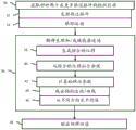
FIG. 1 is a flow diagram of one embodiment of a method for acoustic radiation force ultrasound imaging with axial and/or lateral motion correction;
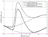
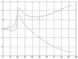
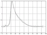
FIG. 2 is a graph illustrating an exemplary displacement profile and physiological motion as a function of time;
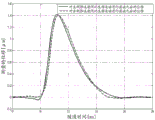
FIG. 3 is a graph illustrating the exemplary displacement profile of FIG. 2 after axial motion correction;
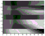
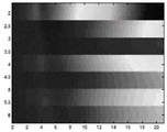
FIGS. 4 and 5 are exemplary displacements over time at various laterally spaced locations caused by push pulses on different sides of a region of interest (ROI);
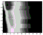
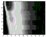
FIGS. 6 and 7 are illustrations of the exemplary displacements of FIGS. 4 and 5 after physiological and/or transducer axial motion;
FIG. 8 illustrates two exemplary displacement profiles resulting from different push pulses and undesired axial motion;
FIG. 9 illustrates an exemplary displacement profile after removal of the undesired axial movement; and
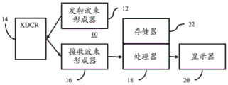
FIG. 10 is a block diagram of one embodiment of a system for acoustic radiation force ultrasound imaging.
Detailed Description
Adaptive physiological motion and transducer motion estimation is provided in acoustic radiation force impulse or imaging (ARFI) applications. Axial and lateral components of physiological and/or transducer motion are adaptively estimated and corrected. Multiple ARFI excitation pulses are used to isolate physiological and transducer displacements from ARFI-induced tissue displacements. In one embodiment, the signal pattern is generated multiple times and used to detect background (physiological) motion. ARFI excitation is used to generate tissue deformation into signal patterns. Physiological motion is filtered out in shear wave velocity or other ARFI imaging.
Figure 1 illustrates a method for acoustic radiation force ultrasound imaging. Typically, a plurality of push pulses are transmitted and a corresponding plurality of displacement profiles are measured for a location. The axial component of the physiological motion can be estimated from the difference between the displacement profiles and removed from the displacement. The lateral component of physiological motion may be removed by averaging values (e.g., velocities) estimated from the displacement profile induced by the multiple push pulses.
The action is performed with an ultrasound imaging system such as that described with respect to figure 10. Data is acquired using a transducer and/or beamformer and a processor estimates displacement from the data. The processor interprets the undesired motion and estimates a viscoelastic parameter value from the resulting information. The ultrasonic imaging system outputs a value of the viscoelastic parameter. Other means, such as a computer or detector, may be used to perform any of the actions.
Additional, different, or fewer acts may be provided in the method of fig. 1. For example, act 48 is not provided. As another example, only lateral motion correction (e.g., acts 42 and 46) illustrating acts (36-46) is performed. In another example, only axial motion correction (e.g., acts 38-44) is performed that illustrates acts (36-46).
The actions are performed in the order described or illustrated. Other sequences may be provided.
In act 30, the ultrasound system acquires tissue displacement (i.e., displacement profile) over time. As the waves caused by the ARFI (e.g., push pulse or acoustic radiation pulse excitation) pass through a location within the patient's body, the tissue is displaced. By scanning the tissue with ultrasound, data for calculating the displacement over time is acquired. Using correlation or other similarity measurements, the displacements represented by scans acquired at different times are determined. The displacement of the wave before it reaches the location and/or after tissue relaxation is also determined.
A displacement profile is obtained in response to the plurality of push pulses. Causing the wave to propagate through the location in response to different push pulses. The displacement caused by the wave generated by each push pulse is measured, resulting in a plurality of displacement profiles.
In act 32, the beamformer generates electrical signals for focused ultrasound transmissions, and the transducer converts the electrical signals into acoustic signals for transmission of push pulses from the transducer. Acoustic radiation force is used. An acoustic stimulus is emitted into the patient. The acoustic excitation acts as a pulsed excitation for causing the displacement. For example, a 400-cycle transmit waveform is transmitted as an acoustic beam with a power or peak amplitude level similar to or lower than that of a B-mode transmit used to image tissue. In one embodiment, the emission is a sequence of shear wave occurrences applied to the field of view. Any ARFI or shear wave imaging sequence may be used.
The emissions are configured with power, amplitude, timing, or other characteristics to induce sufficient stress on the tissue to displace tissue at one or more locations. For example, the transmit focus of the beam is displaced relative to the field of view or ROI to cause displacement throughout the entire field of view or ROI.
Pulsed excitation generates longitudinal or shear waves at a spatial location. In case the excitation is strong enough, a wave is generated. Shear waves propagate through tissue more slowly than longitudinal waves along the direction of acoustic emission, and thus the type of wave can be distinguished in time sequence and/or direction. The difference in timing is used to isolate the shear wave from the longitudinal wave or vice versa. The wave propagates in various directions, such as a direction perpendicular to the direction of the applied stress. The displacement of the wave is greater at a location closer to the focal point at which the wave is generated. As the wave travels, the magnitude of the wave attenuates.
A plurality of push pulses are transmitted in sequence. The tracking of act 34 is performed in response to each push pulse prior to the transmission of the next push pulse. Any number of consecutive push pulses may be transmitted. As a result, a plurality of displacement profiles for the same position but for different periods of time are acquired. Each displacement profile is responsive to a different push pulse, but with the same or similar time sampling.
In one embodiment, the push pulses are focused to different laterally spaced locations. For example, the focus position is at the ROI or on the opposite side of the position where tissue displacement is tracked. The ARFIs are transmitted an equal distance to laterally spaced locations, but on opposite sides of the location for tissue tracking. For a two-dimensional scan, the laterally spaced locations are in the azimuth-axial scan plane (e.g., left and right of the location). For three-dimensional scanning, the laterally spaced locations are on opposite sides in any azimuth-elevation direction. Where more than two push pulses are used, the laterally spaced focal spot locations are evenly distributed around one or more locations to enable tissue displacement measurements. In an alternative embodiment, non-relative and/or non-equal distance focal spot positions relative to one or more tissue displacement positions are used.
In other embodiments, the push pulses are transmitted along the same scan line and/or have the same focal position. Multiple ARFI excitation pulses may be generated on the same side of the ROI or position (with or without the same focal position) used to measure displacement.
In act 34, tissue displacement is tracked. An ultrasound system, such as a processor of the system, tracks displacement in response to the push pulse. The displacement caused by the propagating wave is tracked. The tracking is axial (i.e., one-dimensional tracking of displacement along the scan line), but may be two-dimensional or three-dimensional.
The tracking is over time. The tissue displacement for the location is found for any number of time samples over a period of time during which the wave is expected to be propagated by the location. By tracking each push pulse, a tissue displacement profile of displacement over time is provided.
The time period for tracking may include the time before the transmission of a push pulse and/or wave at the location is reached. Likewise, the period for tracking may include the time after the tissue is relaxed or the entire wave has propagated through the location. For example, let K be the number of reference tracks (i.e., the time during which the tissue is scanned to detect displacement) before the excitation pulse is transmitted or the wave arrives, L be the number of tracks after the excitation pulse or wave arrives, and M-K + L be the total number of tracks. M is large enough that the last N traces have only axial displacement from physiological motion and no displacement from shear waves.
The transducer and beamformer acquire echo data at different times to determine displacement of tissue. The displacement is detected by ultrasonic scanning. Ultrasound data is obtained. At least some of the ultrasound data is responsive to displacement caused by waves or pressure. A region such as a region of interest, an entire field of view, or a sub-region of interest is scanned with ultrasound waves. The region is monitored for shear and longitudinal waves to detect waves. The echo data represents tissue subject to different amounts of pressure at different times. The area is of any size, such as 5 x 5mm in the transverse direction and 10mm in the axial direction. For example, a B-mode scan is performed to detect tissue displacement. The displacement may be detected using doppler, color flow, or other ultrasound modes.
For a given time, ultrasound waves are transmitted to the tissue or region of interest. Any now known or later developed displacement imaging may be used. For example, at less than 720 mW/cm2The intensity of (c) is measured using pulses having a duration of 1-5 cycles. Pulses having other intensities may be used. Scanning is performed for any number of scan lines. For example, eight or sixteen receive beams are formed in a two-dimensional distribution in response to each transmission. After or while applying the stress, B-mode transmission is repeatedly performed along a single transmit scan line and reception is performed along an adjacent receive scan line. In other embodiments, in response to eachA single transmit and only a single receive beam or other number of receive beams. Additional transmit scan lines and corresponding one or more receive lines may be used. Any number of repetitions may be used, such as about 120 or more than 15 ms.
The B-mode intensity may change due to displacement of tissue over time. For the monitored scan lines, a data sequence is provided that represents a temporal profile of tissue motion caused by stress. By performing transmission and reception a plurality of times, data representing regions at different times is received. The transmission and reception are performed a plurality of times to determine a change due to displacement caused by a change in stress. By repeatedly scanning with ultrasound waves, the position of the tissue at different times is determined.
In one embodiment, the displacement is detected for each of a plurality of spatial locations or for a single location. For example, velocity, variance, shift in intensity pattern (e.g., speckle tracking), or other information is detected from the received data as a displacement between two times. An ongoing or series of displacements may be detected for one or more locations.
In one embodiment using B-mode data, data from different scans are axially correlated as a function of time. For each depth or spatial location, correlation within multiple depths or spatial locations (e.g., 64-depth kernel, center depth being the point for which the contour is calculated) is performed. For example, the current data set is correlated with the reference data set a plurality of times. Locations of a subset of data in the reference set centered at the given location are identified in the current set. Different relative translations between the two data sets are performed.
The reference is the first or other data set or data from another scan. The reference set comes from before the stress, but may also come from after the stress. The same reference is used for the entire displacement detection, or the reference data changes in progress or in a moving window.
A level of similarity or correlation of the data at each of the different offset locations is calculated. The translation with the greatest correlation represents the motion vector or offset for the time associated with the current data compared to the reference.
Any now known or later developed correlation may be used, such as cross-correlation, pattern matching, or a minimum sum of absolute differences. Correlating tissue structures and/or spots. Using doppler detection, a clutter filter delivers information associated with moving tissue. The velocity of the tissue is derived from the plurality of echoes. This velocity is used to determine displacement towards or away from the transducer. Alternatively, the relative or difference between the velocities at different locations may be indicative of strain or displacement.
Fig. 2 shows two exemplary displacement profiles for a displacement of a location over time. The amplitude of the distance of the motion vector over time from the reference data is shown. The period of analysis exceeds about 25 milliseconds, but may be longer or shorter (e.g., 12 milliseconds at a 4.8 kHz sampling rate). Other displacement profiles are possible. Any number of positions may be measured for the displacement, such as every millimeter in a 10 x 5mm region of interest or for only one position. The displacement is measured for each position and for each sampling time. As shown in fig. 2, multiple push pulses and corresponding tracking are used to acquire multiple displacement profiles for each position. Similar contours may be calculated for any other location.
The displacement over time and/or space is used for the calculation. In one embodiment, the displacements for different depths are combined, leaving displacements spaced apart in azimuth and/or elevation. For example, the displacement for a given scan line or lateral position is averaged over depth. As an alternative to averaging, a maximum or other selection criterion is used to determine the displacement for a given lateral position. A displacement for only one depth may be used. The displacements for different depths may be used independently.
Referring again to fig. 1, the ultrasound system or processor uses the displacement in response to the multiple push pulses to interpret the physiological motion, the transducer motion, or both the physiological and transducer motion. This undesired motion has both axial and lateral components. The interpretation is for either or both of these components. Displacements from different push pulses are used to account for lateral and/or axial motion caused by forces other than the waves generated by the push pulses.
The actions 38-46 are shown to account for the undesired motion. One or more of the actions may serve additional purposes. For example, act 42 is performed whether or not the motion is being modified. Additional, different, or fewer acts may be provided to account for undesired or non-wave motion.
Interpreting axial motion is independent of interpreting lateral motion. The axial motion may be removed from the displacement of the displacement profile (e.g., acts 38, 40, and 44). The lateral motion may be removed by averaging the viscoelastic parameters calculated from the different displacement profiles (e.g., act 46). In other embodiments, the interpretation may be for only axial motion or for only lateral motion. In the embodiment of fig. 1, both undesired axial and lateral motion are removed.
In act 38, the displacements over time in response to the different push pulses are combined. The contours are aligned in time, such as by shifting one contour in time relative to the other to obtain the best match. In other methods, the peaks are identified and located at the same time.
Once aligned, the displacement magnitudes for each time are combined. Any combination may be used, such as summing, averaging or ratio. In one embodiment, the displacement over time for one profile is subtracted or subtracted from the displacement over time for the other profile. This combination removes or reduces the contribution to the displacement of the ARFI-induced wave.
The axial component of displacement from physiological and/or transducer motion can be modeled as a polynomial of order n. For example, displacements from undesired motion are modeled as third order polynomials. The axial displacement tracked at a given position is given by:

wherein, yl(t) and yr(t) is the measured axial position at time t after the left (l) and right (r) excitations, respectively (i.e., push pulses on opposite sides of the ROI)And (6) moving. Subscripts l and r denote left and right, respectively. The axial displacement induced by the ARFI excitation pulse is x (t), which is generally the same for both the left and right excitations. Modeling physiological and transducer axial displacements with a polynomial whose coefficients are given by al、bl、cl、dlAnd ar、br、cr、drIt is given.
X (t) is removed using the ratio, difference, or other combination of displacement profiles even for periods of time during which the displacement includes a response to ARFI generated waves. For example, by subtracting equation 2 from equation 1, the difference y over time will bediff(t) is provided as:

it is also a third order polynomial. This difference represents the motion that occurs during propagation of the ARFI-induced wave, but does not include displacement from the ARFI-induced wave. As a result, the difference provides physiological and/or transducer motion information during wave travel time and other times.
In act 40, a curve is fitted to the combined displacement (e.g., y for 1: M)diff(t)). Determining coefficients of a polynomial of a model, such as determining al、bl、cl、dlAnd ar、br、cr、dr。
The curve may additionally be fitted to other displacements, such as displacements from different profiles for times that are not subjected to motion from ARFI-induced waves (e.g., part 2 of each of equations 1 and 2-times 1: K and M-N: N). Coefficient al、bl、cl、dlAnd ar、br、cr、drIs determined from the difference in tissue displacement between the push pulses for times responsive to the push pulses and the difference in profile and tissue displacement for times not responsive to the push pulses.
Any curve fit may be used. In one embodiment, the polynomial coefficients are estimated by solving using a least squares method. A polynomial model is least squares fit to tissue displacements for combinations of times responsive to different ARFI induced waves and tissue displacements from contours for times non-responsive to ARFI induced waves. For example, the coefficients of a curve representing displacement due to transducer, physiological, or transducer and physiological axial motion are found using the following least squares fit:

in this matrix, the top row is based on the combined displacement and the lower rows are based on the displacement from the individual contours, but only for times during which motion is not affected by or caused by ARFI induced waves. By using a combined displacement (e.g. y)diff(t)), effectively increasing the number of measurements used for fitting to M samples. The estimate of the polynomial coefficients can be more accurate resulting in an estimate with only the time-limited displacement of the individual displacement profiles (i.e., using only y recorded in the matrix above)lAnd yrValue) than the axial displacement caused by physiology and transducer motion.
The curve defined by the estimation coefficients represents the displacement due to physiological and/or transducer motion without ARFI induced motion. As a result, undesired axial movement over time is provided.
For transverse motion, the interpretation is part of the calculation of the viscoelastic parameters. The calculation of act 42 includes a correction to estimate the axial motion and a removal of the effect of the lateral motion.
In act 42, the processor calculates one or more values of the viscoelastic parameter. Any viscoelastic parameter may be calculated, such as strain, strain rate, young's modulus, elasticity, or other property. In one embodiment, the shear rate is calculated as a visco-elastic parameter.
The value is calculated for each of one or more locations in the ROI. For example, the value is calculated for a single user selected point. As another example, values for various laterally spaced locations in the ROI are calculated.
The value is estimated from one or more displacement profiles. While two or more displacement profiles may be used for each location, only one may be used to estimate the viscoelastic parameter value. Others are used for motion correction. Alternatively, a separate estimate from a separate displacement profile is estimated and used to determine a value for that location.
To estimate this value, in one embodiment, a peak or maximum amplitude in the profile is determined. The time difference between the application of the stress and the peak amplitude indicates the velocity based on the distance of the location from the source of the stress (e.g., the ARFI focus location). In an alternative approach, displacement profiles from different positions are correlated to find the delay between positions. This phase shift can be used to calculate the velocity between the locations associated with the relevant profiles. In other embodiments, the analytical data is calculated from the displacement profile and the elasticity is determined using the phase displacement. The phase difference over time of the displacement of different voxels (voxels) or the zero crossing of the phase for a given voxel indicates the velocity. This velocity can be used to determine other viscoelastic parameters, such as determining young's modulus using shear velocity and known or measured amounts of stress.
The calculation of the viscoelastic parameter value is a function of the motion correction. Acts 44 and 46 provide axial and lateral motion correction, respectively.
In act 44, the axial motion is corrected by altering one or more displacement profiles, which are then used to calculate viscoelastic parameter values. Undesired axial motion is removed from the one or more displacement profiles. Curves representing modeled physiological and/or transducer motion for a given profile are subtracted from the measured displacement profile. In the case of a modeling estimation of the coefficients for each displacement profile, the respective curve is subtracted from the respective displacement profile.
Fig. 2 shows two estimated physiological motions for respective two displacement profiles. For each time, the curve provides the amount of axial motion due to physiological motion. The measured displacement profile includes physiological axial motion and ARFI induced wave motion. By subtracting the physiological axial motion, the resulting displacement profile is of ARFI-induced wave motion without undesired motion. Using equations 1 and 2, the axial displacement x (t) caused by the ARFI excitation pulse is estimated by subtracting the polynomial from the measured displacement y (t). For each time, the axial displacement from the physiological and/or transducer motion is subtracted from the measured displacement. Fig. 3 shows the resulting displacement profile for ARFI-induced wave motion after motion correction, i.e. after filtering (subtraction for each time) to remove undesired axial motion.
After removing the undesired axial motion, a value of the viscoelastic parameter is calculated. For shear velocity, the peak or phasing is used to determine the value. The value is estimated from the result of the subtraction or from a displacement profile that is modified to remove axial motion due to physiological and/or transducer motion.
Where the value is calculated from each different contour for a location, the resulting values may be averaged. Alternatively, selection (e.g., maximum, minimum, or median) is used. In other embodiments, axial motion correction is performed for each of the profiles, and a single value is calculated from the resulting displacement profile.
In act 46 of FIG. 1, the effect of the undesired lateral motion is reduced in the calculation of the value. The reduction of the lateral component of physiological and/or transducer motion also utilizes multiple ARFI excitation pulses on either side of the ROI. Measured displacements in response to ARFI excitations on opposite sides of the position are used. ARFI excitations equally or otherwise distributed around the ROI or a single location are used.
Physiological and transducer motion velocities in the transverse direction within the time interval T are removed from the calculation given the Pulse Repetition Frequency (PRF) and Pulse Repetition Interval (PRI) of the tracking pulses, respectively. The time interval T is given by:
T = 2(PRI _M + texcitation) (5)
wherein, texcitationIs the duration of the ARFI excitation, and M is the total number of trajectory or tracking scans before and after each ARFI excitation. The factor 2 arises from using two ARFI excitations, resulting in two displacement profiles. The lateral rate of physiological motion is assumed to be constant over the interval T (i.e., the lateral displacement due to physiological motion is linear over the interval T).
The lateral motion is in one of two directions (e.g., left or right) relative to position. Since a displacement profile is provided for calculating the value of the viscoelastic parameter resulting from the wave traveling in each of those directions, the resulting value is affected in an opposite manner by undesired lateral motion. The processor calculates different values for the viscoelastic parameter based on the tissue displacement of the different push pulses. For example, one shear velocity is estimated from one displacement profile and another shear velocity for the same location is estimated from another displacement profile. Let v besVelocity of shear wave, vmIs the combined rate of physiological and transducer motion in the transverse direction, vslIs a measured shear wave, v, from the left side excitationsrIs the measured shear wave from the right-hand excitation and x is the distance from the excitation position to the tracking position. X will be considered equal for the left and right rates, but may not be equal in other embodiments. The waves arriving at a lateral distance x from the left and right excitation positions are given by:


Calculating a left excitation velocity v from the respective displacement profilesslAnd a right excitation velocity vsr. The shear wave induced by ARFI excitation has a velocity vsAnd the lateral rate of physiological and transducer motion is vmExpressed by the following formula:


Equation 9 represents the undesired lateral motion. This undesired lateral motion is either calculated or not calculated. This undesired lateral velocity caused by transducer and/or physiological motion is removed by averaging the velocities for shear waves propagating in opposite directions. Alternatively, the undesired velocity is calculated and removed (i.e., subtracted) from one or more of the velocity estimates.
In act 48, a viscoelasticity value is output. In one embodiment, an image is output. After interpreting the undesired lateral and/or axial motion, values for different positions are estimated. The values for the locations in the ROI are determined by parallel receive beamforming and/or repeating the entire process for different locations (e.g., transmission and tracking of ARFI). These values according to space or position are mapped to image values for displaying elasticity or a cut-out image. Any now known or later developed elastography may be used. For example, shear waves, longitudinal waves, strain or other images are generated. An image or a sequence of images is generated.
The elasticity or shear image is displayed separately. Alternatively, B-mode or other images representing the same region or different fields of view are displayed adjacent to the elastic image. In another alternative embodiment, an elasticity or cropping image is combined with or overlaid on the B-mode image.
In another embodiment, the value for the location is output as text, a number, or a code in a chart. For example, the user selects a location on the B-mode image. In response, the ultrasound system calculates a value for the viscoelastic parameter of interest for the selected location. Numeric, textual and/or graphical representations of the calculated values are overlaid on the B-mode image, either independently limited or otherwise communicated to the user. In other embodiments, the output is via transmission over a network and/or provided to storage for storage.
Fig. 2-9 illustrate exemplary results from the removal of undesired axial movement. In vivo liver data obtained in a Virtual Touch Quantification (VTQ) mode (i.e., shear velocity estimation for a user selected point) is used to remove axial displacement from physiology and transducer motion. Fig. 2 shows an example of a displacement profile measured at a given lateral position during an in vivo scan. Fig. 2 also shows the polynomial curve fitted after running the least squares algorithm according to equation 4. Fig. 3 shows displacement profiles from left and right excitation pulses after filtering axial displacement from physiological motion. In other embodiments, the displacement profile is from push pulses focused to the same location but at different times.
Fig. 4 and 5 show displacement maps (displacionmaps) for pushing pulses on opposite sides of the ROI, respectively. The horizontal axis is time and the vertical axis is lateral spacing. For each transmit beam used for tracking, four receive beams are sampled at a given depth. As a result, the measurements for every four laterally spaced locations occur simultaneously. The firing of the push pulses and the corresponding tracking are repeated for each set of four positions, resulting in the horizontal stripe appearance of fig. 4 and 5. Due to axial displacement from physiological motion, the occurrence times of peaks for various locations are partially hidden and not as consistent across locations as desired.
Fig. 6 and 7 show the displacement maps of fig. 4 and 5, respectively, after removal of the axial displacement caused by physiological motion (i.e., for opposite side excitation). Reducing or removing the axial components of the physiology and transducer motion results in a clearer indication of the peak over time for each location and more consistency across locations. In cases where undesired axial motion is removed from displacement, the shear velocity or other viscoelastic parameter value is more likely to be accurate or calculated with greater confidence.
Fig. 8 shows an example of two displacement profiles measured at a given lateral position by transmitting two ARFI excitation pulses (at different times) to the same focus position on the left side of the ROI (i.e., to the left of the measurement position). The two profiles are different because the physiological motion varies over time and the ARFI excitation pulses and associated tracking are performed sequentially. Fig. 9 shows a displacement profile after filtering axial displacement from physiological motion. A curve of the undesired displacements is fitted to the differential displacements for all times and the individual displacements for times before ARFI excitation and after tissue relaxation. The fitted curve is subtracted from the measured displacement. Figure 9 shows that the algorithm accurately removes the axial components of the physiological and transducer motion.
To test the lateral displacement from physiological and/or transducer motion, a linear step translates the transducer array laterally at a constant speed on the surface of a tissue-mimicking phantom (tissue-mimicking phantom). This arrangement mimics the lateral transducer motion. The undesired lateral displacement may be due to transducer motion (e.g., an sonographer rotating and/or translating the transducer), patient motion (e.g., causing the transducer to move relative to the patient), or physiological motion. During lateral motion of the transducer array in the test arrangement, the displacement is measured at a user-selected location using push pulses on opposite sides of the location. The measured shear velocity from the displacement measured from one side is higher than the measured shear velocity from the displacement measured from the opposite side. By reversing the direction of transducer movement, the side with the higher shear velocity changes. The undesired lateral motion increases one speed and decreases the other due to the direction of movement, so averaging reduces the effect of the undesired lateral motion.
FIG. 10 illustrates one embodiment of a system 10 for acoustic radiation force ultrasound imaging. The system 10 implements the method of fig. 1 or other methods. The system 10 includes a transmit beamformer 12, a transducer 14, a receive beamformer 16, an image processor 18, a display 20, and a memory 22. Additional, different, or fewer components may be provided. For example, user input is provided to enable user interaction with the system to select a location for which measurements are to occur.
The system 10 is a medical diagnostic ultrasound imaging system. The system 10 is configured to acquire echo data for shear or other elastography using multiple push pulses. In alternative embodiments, the system 10 is a personal computer, workstation, PACS station, or other arrangement at the same location or distributed over a network to enable real-time or post-acquisition imaging. The system 10 acquires data from memory or another ultrasound imaging system.
The transmit beamformer 12 is an ultrasonic transmitter, memory, pulse generator, analog circuitry, digital circuitry, or a combination thereof. The transmit beamformer 12 is operable to generate waveforms for a plurality of channels at different and/or relative amplitudes, delays and/or orientations. When acoustic waves are transmitted from the transducer 14 in response to the generated electrical waveforms, one or more beams are formed. A sequence of transmit beams is generated to scan a region. Sector, Vector, linear, or other scan formats may be used. The same area is scanned multiple times. For flow or doppler imaging or for shear imaging, a scan sequence along one or more of the same lines is used. In doppler imaging, the sequence may include multiple beams along the same scan line before scanning adjacent scan lines. For shear or longitudinal wave imaging, scanning or frame interleaving may be used (i.e., the entire region is scanned before scanning again). A line or line group of line interleaving may be used. In an alternative embodiment, the transmit beamformer 12 generates plane waves or diverging waves to achieve faster scanning.
The same transmit beamformer 12 may generate pulsed excitation or electrical waveforms in order to generate acoustic energy to induce displacement. An electrical waveform for the acoustic radiation force pulse is generated. In an alternative embodiment, a different transmit beamformer is provided for generating the pulsed excitation. The transmit beamformer 12 causes the transducer 14 to generate push pulses or acoustic radiation force pulses. Using the cross-channel delay profile, the transmit beamformer 12 directs the push pulses to one or more desired focal positions.
The transducer 14 is an array for generating electrical energy from an electrical waveform. For an array, the relative delays focus the acoustic energy. A given transmit event corresponds to the emission of acoustic energy by different elements at substantially the same time with a given delay. The transmit event may provide a pulse of ultrasonic energy for displacing tissue. The pulse is a pulsed excitation or tracking pulse. Pulsed excitation includes waveforms that have many cycles (e.g., 500 cycles) but occur in a relatively short time to cause tissue displacement over a longer time. The tracking pulse may be a B-mode transmission, such as using 1-5 cycles. The tracking pulse is used to scan a portion of the patient experiencing stress variations.
The transducer 14 is a 1-dimensional, 1.25-dimensional, 1.5-dimensional, 1.75-dimensional, or 2-dimensional array of piezoelectric or capacitive thin film elements. An array of wobblers (wobbler) may be used. The transducer 14 includes a plurality of elements for transducing between acoustic and electrical energy. The receive signals are generated in response to the impinging ultrasonic energy (echoes) on the elements of the transducer 14. The elements are connected to channels of the transmit and receive beamformers 12, 16.
The receive beamformer 16 includes a plurality of channels having amplifiers, delays and/or phase rotators and one or more summers. Each channel is associated with one or more transducer elements. The receive beamformer 16 is configured by hardware or software to apply relative delay, phase and/or apodization to form one or more receive beams in response to each imaging or tracking transmission. The receive operation may not occur for echoes from the pulse excitation used to displace tissue. The receive beamformer 16 outputs data representing spatial locations using the receive signals. The relative delay and/or phasing and summing of the signals from the different elements provides beamforming. In an alternative embodiment, the receive beamformer 16 is a processor for generating samples using fourier or other transforms.
The receive beamformer 16 may include a filter, such as a filter for isolating information at a second harmonic or other frequency band relative to the transmit frequency band. Such information may be more likely to include desired tissue, contrast agent, and/or motion information. In another embodiment, the receive beamformer 16 includes a memory or buffer and a filter or summer. Two or more receive beams are combined to isolate information in a desired frequency band, such as the second harmonic, third fundamental, or other band.
In coordination with the transmit beamformer 12, the receive beamformer 16 generates data representing the ROI at different times. After excitation by the acoustic pulses, the receive beamformer 16 generates beams at different times that represent positions along one or more lines. Data (e.g., beamformed samples) are generated by scanning the ROI with ultrasound. By repeating the scan, ultrasound data representing the region at different times of the pulsed excitation is acquired.
The receive beamformer 16 outputs beam-summed data representing one or more spatial locations. Dynamic focusing may be provided. The data may be used for different purposes. For example, a different scan is performed for B-mode or tissue data than for ARFI ultrasound imaging. Alternatively, the B-mode data is also used to determine the viscoelastic parameter values. As another example, data for shear imaging is acquired with a series of shared scans, and B-mode or doppler scans are performed either individually or using some of the same data. The ultrasound or echo data comes from any stage of processing, such as beamforming data before detection or data after detection.
The processor 18 is a B-mode detector, doppler detector, pulsed wave doppler detector, correlation processor, fourier transform processor, application specific integrated circuit, general purpose processor, control processor, image processor, field programmable gate array, graphics processing unit, digital signal processor, analog circuit, digital circuit, combinations thereof or now known or later developed device for detecting and processing information from beamformed ultrasonic samples for display.
In one embodiment, processor 18 includes one or more detectors and a separate processor. An individual processor is a control processor, general processor, digital signal processor, application specific integrated circuit, field programmable gate array, network, server, processor set, graphics processing unit, data path, combinations thereof, or other now known or later developed device for motion correction and/or calculation of values for viscoelastic parameters. The attenuation of the propagation of the shear wave, shear modulus, shear viscosity, shear rate, or one or more other properties may be estimated. For example, a single processor may be configured in hardware and/or software to perform any combination of one or more of acts 36-48 shown in FIG. 1.
The processor 18 is configured to estimate tissue displacement induced by the acoustic pulse excitation. The amount of positional displacement of the tissue is estimated using correlation, tracking, motion detection, or other displacement measurements. The estimation is performed multiple times over a period of time, such as from before tissue movement due to stress, during stress, and after the tissue has largely or completely returned to a relaxed state (e.g., recovered from stress caused by pulsed excitation). The difference in displacement of tissue between locations indicates the relative stiffness or elasticity.
The processor 18 is configured to combine the displacements from the different profiles, such as subtracting one displacement profile from the other. Using the combined displacement, the processor 18 is configured to fit a curve to model axial displacements due to sources other than ARFI induced waves. This curve is subtracted from the measured displacement profile by the processor 18 to isolate the displacement due to the ARFI induced wave.
The processor 18 is configured to estimate a viscoelastic parameter value. Phase change detection, correlation, displacement determination, peak identification, velocity calculation, stress measurement, stress decay, and/or other processes may be used to estimate elasticity, velocity, modulus, or other parameters. The processor 18 is configured to interpret the undesired lateral and/or axial motion in the estimation. By subtracting the undesired axial motion from the displacement profile, the estimate may be more representative of ARFI-induced motion. By averaging the estimates of the values from the displacement profiles generated with the push pulses on the opposite side, the resulting values may have less undesired lateral motion.
The processor 18 is configured to generate one or more images. For example, a shear wave velocity image is generated. Other elastographic images may be generated, such as shear modulus, strain, or strain rate images. The image is presented as an overlay or region of interest within the B-mode image. The elasticity value modulates the color at each location in the region of interest. In the case where the elasticity value is below the threshold value, the B-mode information may be displayed without modulation by the elasticity value. Alternatively or additionally, the values for one or several locations are displayed as text, numerically, and/or in a graph.
The processor 18 operates in accordance with instructions stored in the memory 22 or another memory to implement acoustic radiation force ultrasound imaging. The memory 22 is a non-transitory computer-readable storage medium. The instructions for implementing the processes, methods, and/or techniques discussed herein are provided on a computer-readable storage medium or memory, such as a cache, buffer, RAM, removable media, hard drive, or other computer-readable storage medium. Computer-readable storage media include various types of volatile and nonvolatile storage media. The functions, acts or tasks illustrated in the figures or described herein are performed in response to one or more sets of instructions stored in or on computer readable storage media. The functions, acts or tasks are independent of the particular type of instructions set, storage media, processor or processing strategy and may be performed by software, hardware, integrated circuits, firmware, micro code and the like, operating alone or in combination. Likewise, processing strategies may include multiprocessing, multitasking, parallel processing and the like. In one embodiment, the instructions are stored on a removable media device for reading by local or remote systems. In other embodiments, the instructions are stored at a remote location for transmission over a computer network or over telephone lines. In other embodiments, the instructions are stored within a given computer, CPU, GPU, or system.
The display 20 is a CRT, LCD, projector, plasma display or other display for displaying values, two-dimensional images or three-dimensional representations. The two-dimensional image represents a spatial distribution in an area, such as a plane. The three-dimensional representation is rendered from data representing the spatial distribution in the volume. The display 20 is configured by the processor 18 or other device with input of signals to be displayed as an image. The display 20 displays an image representing the calculated value for the ROI.
Although the invention has been described above by reference to various embodiments, it should be understood that many variations and modifications may be made without departing from the scope of the invention. It is therefore intended that the foregoing detailed description be regarded as illustrative rather than limiting, and that it be understood that it is the following claims, including all equivalents, that are intended to define the spirit and scope of this invention.
Claims (5)
1. A method for acoustic radiation force ultrasound imaging, the method comprising:
sequentially transmitting (32) a plurality of push pulses from the transducer, the push pulses generating (48) waves in tissue of the patient;
tracking (34) tissue displacement in response to the push pulse;
interpreting (36) physiological motion, transducer motion, or both physiological and transducer motion using tissue displacement in response to a plurality of push pulses, the interpreting comprising:
estimating axial motion, the axial motion being caused by the physiological motion, the transducer motion, or the physiological and transducer motion, and the estimating comprising:
fitting a polynomial to a difference of tissue displacement for times responsive to the push pulse and tissue displacement for times not responsive to the push pulse;
calculating (42) a viscoelastic parameter from the displacement and the estimated axial motion; and
an image is generated (48) from the viscoelastic parameters.
2. The method of claim 1, wherein transmitting (32) comprises transmitting (32) at least a first one of the push pulses on a first side of the region of interest and transmitting (32) at least a second one of the push pulses on a second side of the region of interest opposite the first side.
3. The method as recited in claim 1, wherein calculating (42) includes subtracting (44) axial motion over time from a displacement tracked over time and calculating (42) a viscoelastic parameter as a function of the result of subtracting (44).
4. The method of claim 1, wherein interpreting (36) comprises interpreting (36) lateral motion, and wherein calculating (42) comprises reducing the effect of lateral motion in calculating (42).
5. The method of claim 4, wherein interpreting (36) and calculating (42) comprises calculating (42) different values for the viscoelastic parameter from tissue displacement of different push pulses, and averaging (46) the different values, the result of averaging (46) being the calculated viscoelastic parameter.
Applications Claiming Priority (2)
| Application Number | Priority Date | Filing Date | Title |
|---|---|---|---|
| US14/823957 | 2015-08-11 | ||
| US14/823,957 US10582911B2 (en) | 2015-08-11 | 2015-08-11 | Adaptive motion estimation in acoustic radiation force imaging |
Publications (2)
| Publication Number | Publication Date |
|---|---|
| CN106419961A CN106419961A (en) | 2017-02-22 |
| CN106419961B true CN106419961B (en) | 2020-09-15 |
Family
ID=57908366
Family Applications (1)
| Application Number | Title | Priority Date | Filing Date |
|---|---|---|---|
| CN201610656184.6A Active CN106419961B (en) | 2015-08-11 | 2016-08-11 | Adaptive motion estimation in acoustic radiation force imaging |
Country Status (5)
| Country | Link |
|---|---|
| US (1) | US10582911B2 (en) |
| KR (1) | KR101983126B1 (en) |
| CN (1) | CN106419961B (en) |
| DE (1) | DE102016114783A1 (en) |
| FR (1) | FR3039981B1 (en) |
Families Citing this family (12)
| Publication number | Priority date | Publication date | Assignee | Title |
|---|---|---|---|---|
| WO2018191145A1 (en) * | 2017-04-09 | 2018-10-18 | Indiana University Research And Technology Corporation | Motion correction systems and methods for improving medical image data |
| EP3424434A1 (en) * | 2017-07-07 | 2019-01-09 | Koninklijke Philips N.V. | Method and device for processing ultrasound signal data |
| CN107505233A (en) * | 2017-07-21 | 2017-12-22 | 无锡海斯凯尔医学技术有限公司 | Medium viscoplasticity quantitative approach and device |
| CN107440740B (en) * | 2017-07-21 | 2021-06-25 | 无锡海斯凯尔医学技术有限公司 | Method and device for determining viscoelasticity of medium |
| CN107505232B (en) * | 2017-07-21 | 2019-09-03 | 无锡海斯凯尔医学技术有限公司 | Motion information acquisition methods and device |
| US11154277B2 (en) | 2017-10-31 | 2021-10-26 | Siemens Medical Solutions Usa, Inc. | Tissue viscoelastic estimation from shear velocity in ultrasound medical imaging |
| US11464495B2 (en) * | 2018-03-13 | 2022-10-11 | Siemens Medical Solutions Usa, Inc. | Adaptive clutter filtering in acoustic radiation force-based ultrasound imaging |
| CN116869567A (en) * | 2018-05-15 | 2023-10-13 | 深圳迈瑞生物医疗电子股份有限公司 | Shear wave elasticity measurement method and shear wave elasticity imaging system |
| JP7128693B2 (en) | 2018-09-10 | 2022-08-31 | 富士フイルムヘルスケア株式会社 | Ultrasound diagnostic equipment and probe used therefor |
| CN110613484B (en) * | 2019-09-26 | 2021-02-19 | 无锡海斯凯尔医学技术有限公司 | Tissue elasticity detection method and equipment |
| CN110613485B (en) * | 2019-09-26 | 2021-03-23 | 无锡海斯凯尔医学技术有限公司 | Tissue elasticity detection method and equipment |
| CN110927729B (en) * | 2019-11-09 | 2022-04-01 | 天津大学 | Acoustic radiation force pulse elastography method based on displacement attenuation characteristics |
Family Cites Families (23)
| Publication number | Priority date | Publication date | Assignee | Title |
|---|---|---|---|---|
| US8118744B2 (en) * | 2007-02-09 | 2012-02-21 | Duke University | Methods, systems and computer program products for ultrasound shear wave velocity estimation and shear modulus reconstruction |
| US7999945B2 (en) * | 2007-07-18 | 2011-08-16 | The George Washington University | Optical coherence tomography / acoustic radiation force imaging probe |
| US8187187B2 (en) * | 2008-07-16 | 2012-05-29 | Siemens Medical Solutions Usa, Inc. | Shear wave imaging |
| US9364194B2 (en) | 2008-09-18 | 2016-06-14 | General Electric Company | Systems and methods for detecting regions of altered stiffness |
| US8398550B2 (en) * | 2008-12-01 | 2013-03-19 | The Board Of Trustees Of The University Of Illinois | Techniques to evaluate mechanical properties of a biologic material |
| US8147410B2 (en) | 2009-03-23 | 2012-04-03 | The Hong Kong Polytechnic University | Method and apparatus for ultrasound imaging and elasticity measurement |
| JP2012529962A (en) * | 2009-06-19 | 2012-11-29 | コーニンクレッカ フィリップス エレクトロニクス エヌ ヴィ | Imaging system for imaging viscoelastic media |
| US20110060221A1 (en) | 2009-09-04 | 2011-03-10 | Siemens Medical Solutions Usa, Inc. | Temperature prediction using medical diagnostic ultrasound |
| US9351707B2 (en) * | 2010-04-05 | 2016-05-31 | Hitachi Aloka Medical, Ltd. | Methods and apparatus to determine shear wave propagation property |
| WO2011153268A2 (en) * | 2010-06-01 | 2011-12-08 | The Trustees Of Columbia University In The City Of New York | Devices, methods, and systems for measuring elastic properties of biological tissues |
| CN101869485B (en) * | 2010-06-23 | 2012-07-04 | 深圳大学 | Ultrasonic imaging method and device |
| CN101912278A (en) * | 2010-08-12 | 2010-12-15 | 陈庆武 | Ultrasound dynamic elastic imaging probe and method |
| US8727995B2 (en) | 2010-09-09 | 2014-05-20 | Siemens Medical Solutions Usa, Inc. | Reduction of motion artifacts in ultrasound imaging with a flexible ultrasound transducer |
| CN103260525B (en) | 2010-12-13 | 2015-07-15 | 皇家飞利浦电子股份有限公司 | Adjusting measurements of the effects of acoustic radiation force for background motion effects |
| US9237878B2 (en) | 2011-04-22 | 2016-01-19 | Mayo Foundation For Medical Education And Research | Generation and assessment of shear waves in elasticity imaging |
| US8532430B2 (en) | 2011-07-28 | 2013-09-10 | General Electric Company | Methods for reducing motion artifacts in shear wave images |
| US10357226B2 (en) * | 2012-03-12 | 2019-07-23 | Mayo Foundation For Medical Education And Research | System and method for model-independent quantification of tissue viscoelastic properties using ultrasound |
| CN103300890B (en) | 2012-03-16 | 2016-06-08 | 通用电气公司 | For measuring the system and method for tissue mechanical properties |
| CN104203112B (en) | 2012-12-25 | 2017-06-20 | 株式会社日立制作所 | Diagnostic ultrasound equipment and photoelastic evaluation method |
| US9883852B2 (en) | 2013-03-18 | 2018-02-06 | Duke University | Ultrasound systems, methods and computer program products for estimating tissue deformation with harmonic signals |
| CN103519848A (en) * | 2013-10-25 | 2014-01-22 | 中国科学院深圳先进技术研究院 | Tissue displacement estimation method and system based on ultrasonic echo radio frequency signals |
| US10390796B2 (en) * | 2013-12-04 | 2019-08-27 | Siemens Medical Solutions Usa, Inc. | Motion correction in three-dimensional elasticity ultrasound imaging |
| CN104055541A (en) * | 2014-06-26 | 2014-09-24 | 中国科学院苏州生物医学工程技术研究所 | Method for intravascular ultrasound multi-slice shear wave elastography |
-
2015
- 2015-08-11 US US14/823,957 patent/US10582911B2/en active Active
-
2016
- 2016-08-03 FR FR1670434A patent/FR3039981B1/en active Active
- 2016-08-10 DE DE102016114783.4A patent/DE102016114783A1/en active Pending
- 2016-08-10 KR KR1020160101712A patent/KR101983126B1/en active IP Right Grant
- 2016-08-11 CN CN201610656184.6A patent/CN106419961B/en active Active
Also Published As
| Publication number | Publication date |
|---|---|
| FR3039981A1 (en) | 2017-02-17 |
| CN106419961A (en) | 2017-02-22 |
| DE102016114783A1 (en) | 2017-02-16 |
| KR101983126B1 (en) | 2019-05-28 |
| FR3039981B1 (en) | 2020-01-03 |
| US20170042511A1 (en) | 2017-02-16 |
| US10582911B2 (en) | 2020-03-10 |
| KR20170019327A (en) | 2017-02-21 |
Similar Documents
| Publication | Publication Date | Title |
|---|---|---|
| CN106419961B (en) | Adaptive motion estimation in acoustic radiation force imaging | |
| CN104688266B (en) | Motion correction in three-dimensional elastic ultrasound imaging | |
| US8961418B2 (en) | Solving for shear wave information in medical ultrasound imaging | |
| EP2926739B1 (en) | Acquisition control for elasticity ultrasound imaging | |
| US8992426B2 (en) | Feedback in medical ultrasound imaging for high intensity focused ultrasound | |
| US11154277B2 (en) | Tissue viscoelastic estimation from shear velocity in ultrasound medical imaging | |
| CN104510499B (en) | Shear wave detection in medical ultrasound imaging | |
| US10338203B2 (en) | Classification preprocessing in medical ultrasound shear wave imaging | |
| US8801614B2 (en) | On-axis shear wave characterization with ultrasound | |
| US20140276058A1 (en) | Fat Fraction Estimation Using Ultrasound with Shear Wave Propagation | |
| US11006928B2 (en) | Sound speed imaging using shear waves | |
| CN106955125B (en) | Motion independence in acoustic radiation force pulse imaging | |
| CN110893103A (en) | Angle for ultrasound-based shear wave imaging | |
| US11452503B2 (en) | Shear wave imaging based on ultrasound with increased pulse repetition frequency | |
| EP2853918B1 (en) | Shear wave detection in medical ultrasound imaging | |
| US11963824B2 (en) | Shear wave imaging based on ultrasound with increased pulse repetition interval |
Legal Events
| Date | Code | Title | Description |
|---|---|---|---|
| C06 | Publication | ||
| PB01 | Publication | ||
| C10 | Entry into substantive examination | ||
| SE01 | Entry into force of request for substantive examination | ||
| GR01 | Patent grant | ||
| GR01 | Patent grant |