CN106025396B - Power storage device, method for controlling storage battery, and method for controlling information terminal - Google Patents
Power storage device, method for controlling storage battery, and method for controlling information terminal Download PDFInfo
- Publication number
- CN106025396B CN106025396B CN201610124819.8A CN201610124819A CN106025396B CN 106025396 B CN106025396 B CN 106025396B CN 201610124819 A CN201610124819 A CN 201610124819A CN 106025396 B CN106025396 B CN 106025396B
- Authority
- CN
- China
- Prior art keywords
- storage device
- information
- power storage
- controller
- response information
- Prior art date
- Legal status (The legal status is an assumption and is not a legal conclusion. Google has not performed a legal analysis and makes no representation as to the accuracy of the status listed.)
- Active
Links
Images


Classifications
-
- H—ELECTRICITY
- H02—GENERATION; CONVERSION OR DISTRIBUTION OF ELECTRIC POWER
- H02J—CIRCUIT ARRANGEMENTS OR SYSTEMS FOR SUPPLYING OR DISTRIBUTING ELECTRIC POWER; SYSTEMS FOR STORING ELECTRIC ENERGY
- H02J7/00—Circuit arrangements for charging or depolarising batteries or for supplying loads from batteries
- H02J7/34—Parallel operation in networks using both storage and other dc sources, e.g. providing buffering
- H02J7/35—Parallel operation in networks using both storage and other dc sources, e.g. providing buffering with light sensitive cells
-
- H—ELECTRICITY
- H01—ELECTRIC ELEMENTS
- H01M—PROCESSES OR MEANS, e.g. BATTERIES, FOR THE DIRECT CONVERSION OF CHEMICAL ENERGY INTO ELECTRICAL ENERGY
- H01M10/00—Secondary cells; Manufacture thereof
- H01M10/42—Methods or arrangements for servicing or maintenance of secondary cells or secondary half-cells
- H01M10/48—Accumulators combined with arrangements for measuring, testing or indicating the condition of cells, e.g. the level or density of the electrolyte
- H01M10/482—Accumulators combined with arrangements for measuring, testing or indicating the condition of cells, e.g. the level or density of the electrolyte for several batteries or cells simultaneously or sequentially
-
- H—ELECTRICITY
- H01—ELECTRIC ELEMENTS
- H01M—PROCESSES OR MEANS, e.g. BATTERIES, FOR THE DIRECT CONVERSION OF CHEMICAL ENERGY INTO ELECTRICAL ENERGY
- H01M10/00—Secondary cells; Manufacture thereof
- H01M10/42—Methods or arrangements for servicing or maintenance of secondary cells or secondary half-cells
- H01M10/425—Structural combination with electronic components, e.g. electronic circuits integrated to the outside of the casing
- H01M10/4257—Smart batteries, e.g. electronic circuits inside the housing of the cells or batteries
-
- H—ELECTRICITY
- H01—ELECTRIC ELEMENTS
- H01M—PROCESSES OR MEANS, e.g. BATTERIES, FOR THE DIRECT CONVERSION OF CHEMICAL ENERGY INTO ELECTRICAL ENERGY
- H01M10/00—Secondary cells; Manufacture thereof
- H01M10/42—Methods or arrangements for servicing or maintenance of secondary cells or secondary half-cells
- H01M10/48—Accumulators combined with arrangements for measuring, testing or indicating the condition of cells, e.g. the level or density of the electrolyte
- H01M10/488—Cells or batteries combined with indicating means for external visualization of the condition, e.g. by change of colour or of light density
-
- H—ELECTRICITY
- H02—GENERATION; CONVERSION OR DISTRIBUTION OF ELECTRIC POWER
- H02J—CIRCUIT ARRANGEMENTS OR SYSTEMS FOR SUPPLYING OR DISTRIBUTING ELECTRIC POWER; SYSTEMS FOR STORING ELECTRIC ENERGY
- H02J13/00—Circuit arrangements for providing remote indication of network conditions, e.g. an instantaneous record of the open or closed condition of each circuitbreaker in the network; Circuit arrangements for providing remote control of switching means in a power distribution network, e.g. switching in and out of current consumers by using a pulse code signal carried by the network
- H02J13/00006—Circuit arrangements for providing remote indication of network conditions, e.g. an instantaneous record of the open or closed condition of each circuitbreaker in the network; Circuit arrangements for providing remote control of switching means in a power distribution network, e.g. switching in and out of current consumers by using a pulse code signal carried by the network characterised by information or instructions transport means between the monitoring, controlling or managing units and monitored, controlled or operated power network element or electrical equipment
- H02J13/00022—Circuit arrangements for providing remote indication of network conditions, e.g. an instantaneous record of the open or closed condition of each circuitbreaker in the network; Circuit arrangements for providing remote control of switching means in a power distribution network, e.g. switching in and out of current consumers by using a pulse code signal carried by the network characterised by information or instructions transport means between the monitoring, controlling or managing units and monitored, controlled or operated power network element or electrical equipment using wireless data transmission
-
- H—ELECTRICITY
- H02—GENERATION; CONVERSION OR DISTRIBUTION OF ELECTRIC POWER
- H02J—CIRCUIT ARRANGEMENTS OR SYSTEMS FOR SUPPLYING OR DISTRIBUTING ELECTRIC POWER; SYSTEMS FOR STORING ELECTRIC ENERGY
- H02J7/00—Circuit arrangements for charging or depolarising batteries or for supplying loads from batteries
- H02J7/0047—Circuit arrangements for charging or depolarising batteries or for supplying loads from batteries with monitoring or indicating devices or circuits
- H02J7/0048—Detection of remaining charge capacity or state of charge [SOC]
-
- H—ELECTRICITY
- H01—ELECTRIC ELEMENTS
- H01M—PROCESSES OR MEANS, e.g. BATTERIES, FOR THE DIRECT CONVERSION OF CHEMICAL ENERGY INTO ELECTRICAL ENERGY
- H01M10/00—Secondary cells; Manufacture thereof
- H01M10/42—Methods or arrangements for servicing or maintenance of secondary cells or secondary half-cells
- H01M10/425—Structural combination with electronic components, e.g. electronic circuits integrated to the outside of the casing
- H01M2010/4278—Systems for data transfer from batteries, e.g. transfer of battery parameters to a controller, data transferred between battery controller and main controller
-
- Y—GENERAL TAGGING OF NEW TECHNOLOGICAL DEVELOPMENTS; GENERAL TAGGING OF CROSS-SECTIONAL TECHNOLOGIES SPANNING OVER SEVERAL SECTIONS OF THE IPC; TECHNICAL SUBJECTS COVERED BY FORMER USPC CROSS-REFERENCE ART COLLECTIONS [XRACs] AND DIGESTS
- Y02—TECHNOLOGIES OR APPLICATIONS FOR MITIGATION OR ADAPTATION AGAINST CLIMATE CHANGE
- Y02B—CLIMATE CHANGE MITIGATION TECHNOLOGIES RELATED TO BUILDINGS, e.g. HOUSING, HOUSE APPLIANCES OR RELATED END-USER APPLICATIONS
- Y02B90/00—Enabling technologies or technologies with a potential or indirect contribution to GHG emissions mitigation
- Y02B90/20—Smart grids as enabling technology in buildings sector
-
- Y—GENERAL TAGGING OF NEW TECHNOLOGICAL DEVELOPMENTS; GENERAL TAGGING OF CROSS-SECTIONAL TECHNOLOGIES SPANNING OVER SEVERAL SECTIONS OF THE IPC; TECHNICAL SUBJECTS COVERED BY FORMER USPC CROSS-REFERENCE ART COLLECTIONS [XRACs] AND DIGESTS
- Y02—TECHNOLOGIES OR APPLICATIONS FOR MITIGATION OR ADAPTATION AGAINST CLIMATE CHANGE
- Y02E—REDUCTION OF GREENHOUSE GAS [GHG] EMISSIONS, RELATED TO ENERGY GENERATION, TRANSMISSION OR DISTRIBUTION
- Y02E40/00—Technologies for an efficient electrical power generation, transmission or distribution
- Y02E40/70—Smart grids as climate change mitigation technology in the energy generation sector
-
- Y—GENERAL TAGGING OF NEW TECHNOLOGICAL DEVELOPMENTS; GENERAL TAGGING OF CROSS-SECTIONAL TECHNOLOGIES SPANNING OVER SEVERAL SECTIONS OF THE IPC; TECHNICAL SUBJECTS COVERED BY FORMER USPC CROSS-REFERENCE ART COLLECTIONS [XRACs] AND DIGESTS
- Y02—TECHNOLOGIES OR APPLICATIONS FOR MITIGATION OR ADAPTATION AGAINST CLIMATE CHANGE
- Y02E—REDUCTION OF GREENHOUSE GAS [GHG] EMISSIONS, RELATED TO ENERGY GENERATION, TRANSMISSION OR DISTRIBUTION
- Y02E60/00—Enabling technologies; Technologies with a potential or indirect contribution to GHG emissions mitigation
- Y02E60/10—Energy storage using batteries
-
- Y—GENERAL TAGGING OF NEW TECHNOLOGICAL DEVELOPMENTS; GENERAL TAGGING OF CROSS-SECTIONAL TECHNOLOGIES SPANNING OVER SEVERAL SECTIONS OF THE IPC; TECHNICAL SUBJECTS COVERED BY FORMER USPC CROSS-REFERENCE ART COLLECTIONS [XRACs] AND DIGESTS
- Y04—INFORMATION OR COMMUNICATION TECHNOLOGIES HAVING AN IMPACT ON OTHER TECHNOLOGY AREAS
- Y04S—SYSTEMS INTEGRATING TECHNOLOGIES RELATED TO POWER NETWORK OPERATION, COMMUNICATION OR INFORMATION TECHNOLOGIES FOR IMPROVING THE ELECTRICAL POWER GENERATION, TRANSMISSION, DISTRIBUTION, MANAGEMENT OR USAGE, i.e. SMART GRIDS
- Y04S10/00—Systems supporting electrical power generation, transmission or distribution
- Y04S10/12—Monitoring or controlling equipment for energy generation units, e.g. distributed energy generation [DER] or load-side generation
- Y04S10/123—Monitoring or controlling equipment for energy generation units, e.g. distributed energy generation [DER] or load-side generation the energy generation units being or involving renewable energy sources
-
- Y—GENERAL TAGGING OF NEW TECHNOLOGICAL DEVELOPMENTS; GENERAL TAGGING OF CROSS-SECTIONAL TECHNOLOGIES SPANNING OVER SEVERAL SECTIONS OF THE IPC; TECHNICAL SUBJECTS COVERED BY FORMER USPC CROSS-REFERENCE ART COLLECTIONS [XRACs] AND DIGESTS
- Y04—INFORMATION OR COMMUNICATION TECHNOLOGIES HAVING AN IMPACT ON OTHER TECHNOLOGY AREAS
- Y04S—SYSTEMS INTEGRATING TECHNOLOGIES RELATED TO POWER NETWORK OPERATION, COMMUNICATION OR INFORMATION TECHNOLOGIES FOR IMPROVING THE ELECTRICAL POWER GENERATION, TRANSMISSION, DISTRIBUTION, MANAGEMENT OR USAGE, i.e. SMART GRIDS
- Y04S40/00—Systems for electrical power generation, transmission, distribution or end-user application management characterised by the use of communication or information technologies, or communication or information technology specific aspects supporting them
- Y04S40/12—Systems for electrical power generation, transmission, distribution or end-user application management characterised by the use of communication or information technologies, or communication or information technology specific aspects supporting them characterised by data transport means between the monitoring, controlling or managing units and monitored, controlled or operated electrical equipment
- Y04S40/126—Systems for electrical power generation, transmission, distribution or end-user application management characterised by the use of communication or information technologies, or communication or information technology specific aspects supporting them characterised by data transport means between the monitoring, controlling or managing units and monitored, controlled or operated electrical equipment using wireless data transmission
Abstract
The present disclosure provides a power storage device, a control method of a storage battery, and a control method of an information terminal. An electricity storage device (200) is connected to the guide lamp (100). The power storage device (200) is provided with: a storage battery (201); a first communicator (205) that communicates with an external communication apparatus by short-range wireless communication; and a first controller (203) that, when the first communicator (205) receives, from an external communication device, a request signal requesting information on whether or not the power supply operation of the power storage device (200) to the guidance lamp (100) is normal, causes the first communicator (205) to transmit response information including the information on whether or not the power supply operation is normal to a transmission source of the request signal, and causes the first communicator (205) to transmit the request signal to another power storage device.
Description
Technical Field
The present disclosure relates to a power storage device mounted on an electrical apparatus and used for supplying electric power to the electrical apparatus, and more particularly, to a technique for notifying a user of a state of electric power supplied from the power storage device to the electrical apparatus.
Background
The power storage device is mounted on a mobile vehicle such as an electric power assisted bicycle or an electric vehicle and supplies electric power. The power storage device is used to efficiently operate power generation equipment such as a solar power generator and a fuel cell.
According to patent document 1, the power storage device is configured to incorporate a plurality of battery packs. Each battery pack receives information indicating the remaining capacity and the like of the other battery pack from the other battery pack by the short-range wireless communication, and transmits the information to the other battery pack. In this way, the power storage device can collect the remaining capacities of the plurality of battery packs.
Documents of the prior art
Patent document
Patent document 1: international publication No. 2014/155903
As described above, according to patent document 1, in the power storage device including a plurality of battery packs, although the remaining capacities of the plurality of battery packs and the like can be collected, there is room for improvement.
Disclosure of Invention
Problems to be solved by the invention
In view of the above, a non-limiting exemplary embodiment provides a power storage device capable of checking a state of power supply to an electric device.
Means for solving the problems
An aspect of the present disclosure relates to a power storage device mounted on an electrical apparatus, the power storage device including: a storage battery; a 1 st communicator that communicates with an external communication apparatus by short-range wireless communication; and a controller that, when the 1 st communicator receives a request signal requesting at least one of 1 st information and 2 nd information from the external communication device, causes the 1 st communicator to transmit response information including at least one of the 1 st information and the 2 nd information to a transmission source of the request signal, and causes the 1 st communicator to transmit the request signal to another power storage device, wherein the 1 st information is information on whether or not an operation of supplying power to the electrical device by the power storage device is normal, and the 2 nd information is information on whether or not an operation of the electrical device using the power supplied from the power storage device is normal.
ADVANTAGEOUS EFFECTS OF INVENTION
According to the present disclosure, it is possible to confirm whether or not the power supply operation for supplying power from the power storage device to the electrical device is normal for the power storage device mounted on the electrical device.
Drawings
Fig. 1 is a system configuration diagram showing a configuration of a spot inspection system 10 according to embodiment 1.
Fig. 2 is a block diagram showing a functional configuration of the information terminal 300.
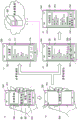
Fig. 3 is an exploded perspective view of the guide lamp 100 and the power supply device 210.
Fig. 4 is a block diagram showing the functional configurations of the guidance lamp 100 and the power storage device 200.
Fig. 5 shows an example of the data structure of the response information 251.
Fig. 6 is a sequence diagram (1) showing the operation in the spot inspection system 10.
Fig. 7 is a sequence diagram (2) showing the operation in the spot inspection system 10.
Fig. 8 is a sequence diagram (3) showing the operation in the spot inspection system 10.
Fig. 9 is a system configuration diagram showing a configuration of the spot inspection system 20 according to embodiment 2.
Fig. 10 is a block diagram showing the functional configuration of the streetlamp 500 and the power storage device 200.
Fig. 11 is a block diagram showing a functional configuration of a street lamp 500h and a power storage device 200h according to modification 1.
Fig. 12 is a sequence diagram showing the operation in modification 1.
Fig. 13 is a block diagram showing a functional configuration of a street lamp 500i and a power storage device 200i according to modification 2.
Fig. 14 is a sequence diagram (1) showing the operation in modification 2.
Fig. 15 is a sequence diagram (2) showing the operation in modification 2.
Fig. 16 is a block diagram of a functional configuration of a street lamp 500j and a power storage device 200j according to modification 3.
Fig. 17 is a sequence diagram showing the operation in modification 3.
Fig. 18 is a sequence diagram showing the operation in modification 4.
Fig. 19 is a block diagram showing a functional configuration of a street lamp 500k and a power storage device 200k according to modification 5.
Fig. 20 shows a supplementary explanation of the operation test condition table 551.
Fig. 21 is a flowchart showing a process of a work confirmation test, which will be described later.
Fig. 22 shows transition of a screen displayed on the touch panel 309.
Detailed Description
The conventional technology described in patent document 1 can acquire information on the states of voltage, temperature, and the like of a plurality of battery packs that are not mounted on an electrical device. However, it is not considered to confirm whether or not the power supply operation for supplying power from the battery pack mounted on the electrical device to the electrical device is normal.
Then, the present inventors have conducted intensive studies and, as a result, have conceived the following.
That is, one aspect of the present disclosure relates to a power storage device mounted on an electrical apparatus, the power storage device including: a storage battery; a 1 st communicator that communicates with an external communication apparatus by short-range wireless communication; and a controller that, when the 1 st communicator receives a request signal requesting at least one of 1 st information and 2 nd information from the external communication device, causes the 1 st communicator to transmit response information including at least one of the 1 st information and the 2 nd information to a transmission source of the request signal, and causes the 1 st communicator to transmit the request signal to another power storage device, wherein the 1 st information is information on whether or not an operation of supplying power to the electrical device by the power storage device is normal, and the 2 nd information is information on whether or not an operation of the electrical device using the power supplied from the power storage device is normal.
Thus, the state of power supply from the power storage device to the electrical device can be confirmed for the plurality of power storage devices mounted on the electrical device.
Hereinafter, a power storage device and a control method of an information terminal according to one embodiment of the present disclosure will be described in detail with reference to the drawings.
The embodiments described below are all specific examples of the present disclosure. The numerical values, shapes, materials, constituent elements, arrangement positions and connection modes of the constituent elements, steps, order of the steps, and the like shown in the following embodiments are examples, and are not intended to limit the present disclosure. In the following embodiments, components not described in the independent claims indicating the highest concept will be described as arbitrary components.
(embodiment mode 1)
A point inspection system 10 according to embodiment 1 of the present disclosure will be described.
Fig. 1 is a system configuration diagram showing a configuration of a spot inspection system 10.
As shown in fig. 1, the checkup system 10 includes guidance lights 100a, 100b, 100c, 100d, · · information terminal 300, and a server device 400.
The guidance lights 100a, 100b, 100c, 100d, · · are spaced apart by a predetermined interval on the road and are arranged in a row in this order.
The power storage device 200a is connected to the guidance lamp 100 a. The guidance lamp 100a operates using the electric power supplied from the power storage device 200 a. The power storage device 200a outputs dc power. The guidance light 100a may be a direct current type or an alternating current type. When the guidance lamp 100a is of the AC system, the DC power from the power storage device 200a is converted into the AC power by a DC/AC Converter (DC/AC Converter) provided in the guidance lamp 100 a. The guidance lamp 100a includes an operating device 103 that operates using the electric power supplied from the power storage device 200a, and the main function of the electrical device (e.g., the guidance lamp) is realized by the operation of the operating device 103. As an example, the operator 103 is a luminaire, being a LED (Light Emitting Diode). The illuminator emits light using the electric power supplied from the power storage device 200 a. The guidance lights 100b, 100c, 100d, · · are also configured similarly to the guidance light 100a, and power storage devices 200b, 200c, 200d, · · are connected to the guidance lights 100b, 100c, 100d, · · respectively. Thus, the guidance lights 100a, 100b, 100c, 100d, · · illuminate the road, and thus the pedestrian can walk with caution even at night. The guidance light is one example of the electrical apparatus of the present disclosure.
There is a possibility that an abnormality may occur in the power supply from the power storage device to each of the guidance lamps or that the guidance lamp (for example, the operating device 103 of the guidance lamp) may malfunction. Then, the examiner of the examination system 10 performs examination as follows.
The examiner who holds the information terminal 300 stands within a range in which wireless communication with the power storage device 200a of the guidance lamp 100a is possible. By the operation of the inspector, the information terminal 300 transmits a request signal requesting information on whether or not the power supply operation of supplying power from the power storage device to the guidance lamp is normal, by the short-range wireless communication.
When the power storage device 200a of the guidance lamp 100a receives the request signal from the information terminal 300 by the short-range wireless communication, the same request signal is transmitted by the short-range wireless communication. Next, when the power storage device 200b of the guidance lamp 100b receives the request signal from the power storage device 200a of the guidance lamp 100a by the short-range wireless communication, the same request signal is transmitted by the short-range wireless communication. Next, when the power storage device 200c of the guidance lamp 100c receives the request signal from the power storage device 200b of the guidance lamp 100b by the short-range wireless communication, the same request signal is transmitted by the short-range wireless communication.
In this way, the same request signal is transmitted in a relay manner to the power storage devices of the sequentially adjacent guidance lamps starting from the information terminal 300.
When the power storage device 200a of the guidance lamp 100a receives the request signal from the information terminal 300 by the short-range wireless communication, the power storage device 200a generates response information including information on whether or not the power supply operation to the guidance lamp 100a by the power storage device 200a is normal. Next, the power storage device 200a of the guidance lamp 100a transmits the generated response information by the short-range wireless communication. The information terminal 300 receives the response information generated by the power storage device 200a of the guidance lamp 100a through the short-range wireless communication.
When the power storage device 200b of the guidance lamp 100b receives the request signal from the power storage device 200a of the guidance lamp 100a by the short-range wireless communication, the power storage device 200b generates response information including information on whether or not the power supply operation to the guidance lamp 100b by the power storage device 200b is normal. Next, the power storage device 200b of the guidance lamp 100b transmits the generated response information by the short-range wireless communication. The power storage device 200a of the guide lamp 100a receives the response information from the power storage device 200b of the guide lamp 100b by the short-range wireless communication. Upon receiving the response information, the power storage device 200a of the guidance lamp 100a transmits the response information received from the power storage device 200b of the guidance lamp 100b by the short-range wireless communication. The information terminal 300 receives the response information generated by the power storage device 200b of the guide lamp 100b via the power storage device 200a of the guide lamp 100a by the short-range wireless communication.
When the power storage device 200c of the guide lamp 100c receives the request signal from the power storage device 200b of the guide lamp 100b by the short-range wireless communication, the power storage device 200c generates response information including information on whether or not the power supply operation to the guide lamp 100c by the power storage device 200c is normal. Next, the power storage device 200c of the guidance lamp 100c transmits the generated response information by the short-range wireless communication. The power storage device 200b of the guide lamp 100b receives the response information from the power storage device 200c of the guide lamp 100c by the short-range wireless communication. Upon receiving the response information, the power storage device 200b of the guidance lamp 100b transmits the response information received from the power storage device 200c of the guidance lamp 100c by the short-range wireless communication. Upon receiving the response information, the power storage device 200a of the guidance lamp 100a transmits the response information received from the power storage device 200b of the guidance lamp 100b by the short-range wireless communication. The information terminal 300 receives the response information generated by the power storage device 200c of the guide lamp 100c via the power storage device 200a of the guide lamp 100a by the short-range wireless communication.
In this way, the power storage device provided in each guidance lamp transmits response information including information on whether or not the power supply operation performed by the power storage device itself is normal to the information terminal 300 as it is, or transmits the response information to the information terminal 300 via the power storage device provided in the guidance lamp interposed between the power storage device and the information terminal 300.
The information terminal 300 collects response information from the respective power storage devices of the guidance lamps 100a, 100b, 100c, 100d, ·. Information on whether or not the power supply operation to each guidance lamp is normal is displayed on the display surface of the information terminal 300 based on the collected response information.
As an example, the information terminal 300 and the server apparatus 400 are connected to each other via a mobile phone network and the internet.
The information terminal 300 transmits response information collected from the power storage device of each guidance lamp to the server device 400 via the portable communicator 301 by the control of the controller 303. The timing of transmitting the collected response information to the server apparatus 400 is arbitrary. Specifically, in a state where there is no instruction from the user of the information terminal 300, the response information may be transmitted to the server apparatus 400 in accordance with the collection of the response information under the control of the controller 303, or the collected response information may be periodically transmitted to the server apparatus. Further, after receiving an instruction from the user of the information terminal 300, the controller 303 may transmit the collected response information to the server apparatus 400.
The server device 400 receives response information collected by the power storage device of each guidance lamp from the information terminal 300, and stores the received response information. Further, the server apparatus 400 may be a cloud server apparatus. Here, the cloud server device is a server device that provides various services to users via a network such as the internet.
In embodiment 1, a direction from the information terminal 300 to the guidance lamp 100a, from the guidance lamp 100a to the guidance lamp 100b, from the guidance lamp 100b to the guidance lamp 100c, and from the guidance lamp 100c to the guidance lamp 100d is referred to as a downstream direction (or a downstream side). The downstream direction is the direction in which the desired signal is transmitted. On the other hand, the direction from the guide lamp 100d to the guide lamp 100c, from the guide lamp 100c to the guide lamp 100b, from the guide lamp 100b to the guide lamp 100a, and from the guide lamp 100a to the information terminal 300 is referred to as the upstream direction (or upstream side). The upstream direction is the direction in which the response information is transferred.
The information terminal 300 transmits a request signal requesting information on whether or not the power supply operation of the power storage device to the guidance lamp is normal, by the short-range wireless communication, in accordance with the operation of the user. The information terminal 300 receives response information including information on whether or not the power supply operation to the guidance lamp by the power storage device is normal, through the short-range wireless communication. Then, the information terminal 300 displays, on the display surface, information about whether or not the power supply operation of the power storage device is normal, which is included in the received response information.
In other words, the information terminal 300 operates according to the control method of steps a to c described below.
The method includes the step of (a) transmitting a request signal requesting information on whether or not the power supply operation to the electrical device by the power storage device is normal to the power storage device.
(step b) response information including information on whether or not the power supply operation from the power storage device is normal, which is transmitted from the power storage device in response to the request signal, is acquired.
(step c) information on whether or not the power supply operation by the power storage device is normal, which is included in the acquired response information, is displayed on the display screen of the information terminal 300.
Here, the response information may include information on whether or not the power supply operation by the plurality of power storage devices is normal. At this time, in step (c), information regarding whether or not the power supply operation by the plurality of power storage devices is normal is displayed in a list on the list screen 341 of the information terminal.
Fig. 2 is a block diagram showing a functional configuration of the information terminal 300.
As shown in fig. 2, the information terminal 300 includes a portable communicator 301, a short-range wireless communicator 302, a controller 303, an information memory 304, a voice controller 305, an input/output controller 306, a speaker 307, a microphone 308, a touch panel 309, and a button input unit 310.
The information terminal 300 is specifically a computer system including a microprocessor, a signal processing processor, a ROM (Read only Memory), a RAM (Random-Access Memory), and the like. The RAM stores a computer program. The microprocessor and the signal processing processor operate according to a computer program. Thus, the portable communicator 301, the short-range wireless communicator 302, the controller 303, the audio controller 305, and the input/output controller 306 realize their functions.
As an example, the information terminal 300 is a smartphone. The information terminal 300 may be a tablet computer, a mobile phone, a personal computer, or the like.
As an example, the information memory 304 includes a nonvolatile semiconductor memory.
The information storage 304 has an area for storing the received 1 or more pieces of response information.
The mobile communication device 301 realizes mobile communication based on, for example, CDMA (Code Division Multiple Access) 2000, LTE (Long Term Evolution), or other standards.
As an example, the short-range wireless communicator 302 performs communication by short-range wireless based on the standard of ieee802.15.1(Bluetooth (registered trademark)), Bluetooth). The signal transmitted from the short-range wireless communication device 302 is radiated toward the periphery of the short-range wireless communication device 302 without directivity. The short-range wireless communication device 302 may perform communication by a short-range wireless method based on a short-range wireless communication standard defined by ZigBee (ZigBee).
The microphone 308 generates an audio signal as an analog electric signal by vibrating a coil in a magnetic field with a diaphragm that vibrates upon receiving an acoustic wave.
The speaker 307 receives a sound signal as an analog electric signal from the sound controller 305, and vibrates the diaphragm in accordance with the received sound signal to output a sound wave.
The sound controller 305 decodes the encoded sound information, converts it into an analog electric signal, and outputs it to the speaker 307. The sound controller 305 converts the sound signal received from the microphone 308 into a digital electric signal, and outputs the encoded sound information to the portable communicator 301.
The touch panel 309 includes a display panel device having a rectangular display surface and a touch panel device attached to the display surface. As an example, the display panel device is a liquid crystal display. The touch panel device detects contact of an operation body such as a finger of a user with the operation surface of the touch panel 309.
The touch panel 309 displays a list screen 341 as an example via the input/output controller 306 under the control of the controller 303. As shown in fig. 1, the list screen 341 includes an inspection area 331, a list 332, a message 333, and a message 334.
The inspection area 331 receives a touch operation by the user. When the inspection area 331 is touched, the touch panel 309 outputs a confirmation start instruction for starting the confirmation of the state of the power supply operation of the power storage device of the guidance lamps 100a, 100b, 100c, 100d, · · to the controller 303 via the input/output controller 306. The confirmation may include not only confirmation of the state of the power supply operation by the power storage device but also confirmation of the state of the operation of the pilot lamp using the power supplied from the power storage device. The above-described confirmation start instruction is an example of the request signal of the present disclosure.
The list 332 displays whether or not the power supply operation by the power storage device is normal for each of the guidance lamps 100a, 100b, 100c, 100d, ·. When the confirmation includes not only the confirmation of the state of the power supply operation by the power storage device but also the confirmation of the state of the operation of the guidance lamp, both results may be displayed together or may be displayed separately. In this example, reference numeral 335 corresponds to identification information of the pilot lamp, and 336 corresponds to information on whether or not the power supply operation by the power storage device is normal.
The message 333 indicates whether the power supply operation by the power storage device is normal for all of the guidance lamps 100a, 100b, 100c, 100d, · · · and also whether the power supply operation by the power storage device is abnormal for some of the guidance lamps.
The message 334 displays confirmation that the power supply operation by the power storage device is completed for the guidance lamps 100a, 100b, 100c, 100d, ·.
The button input unit 310 includes a plurality of buttons. Each button is operated by being pressed by the user.
The input-output controller 306 relays information between the button inputter 310 and the touch panel 309 and the controller 303.
The controller 303 controls the portable communicator 301, the short range wireless communicator 302, the information memory 304, the sound controller 305, and the input/output controller 306.
In addition, the controller 303 receives a confirmation start instruction from the touch panel 309 via the input-output controller 306. Upon receiving the confirmation start instruction, the controller 303 generates a request signal requesting information on whether or not the power supply operation to the electrical equipment by the power storage device of each guidance lamp is normal. Next, the controller 303 outputs the generated request information to the short-range wireless communicator 302 to transmit the request information.
In addition, the controller 303 receives response information from the guidance lamp 100a via the short range wireless communicator 302. Upon receiving the response information, the controller 303 writes the received response information to the information memory 304. Next, the controller 303 reads out the response information from the information memory 304, and generates a list to be displayed on the touch panel 309 using the read-out response information. The list includes a number for identifying each of the guidance lamps 100a, 100b, 100c, 100d, · · and an operation confirmation result of each of the guidance lamps in association with the number. The controller 303 outputs the generated list to the touch panel 309 via the input/output controller 306.
The controller 303 may have a control function, and may include an arithmetic processor (not shown) and a memory (not shown) for storing a control program. Examples of the arithmetic processor include an MPU (Microprocessor Unit) and a CPU (Central Processing Unit). As the memory, a memory (memory) can be exemplified. The controller 303 may be a single controller that performs centralized control, or may be a plurality of controllers that perform distributed control in cooperation with each other.
The transition of the screen displayed on the touch panel 309 will be described with reference to fig. 22. Further, fig. 22(a) - (e) show transition examples of screens displayed on the touch panel 309, respectively.
In each case, the touch panel 309 displays screens 351, 352, 353, 354, and 355 shown in the figure.
In the information terminal 300, when an inspection system, which is an application program for collecting the power supply operation status of the power storage devices of the guidance lights 100a, 100b, 100c, 100d, · · · is executed, the touch panel 309 displays a screen 351 shown in (a) of fig. 22.
As shown in fig. 22(a), the screen 351 includes a title 360, a button 361, a button 362, and a button 363. The title 360, button 361, button 362, and button 363 display "inspection system", "inspection start", "setting", and "past record", respectively.
When the user operates the button 361, the collection of the power supply operation state of the power storage device of the guidance lamps 100a, 100b, 100c, 100d, · · and then displays a screen 352 shown in fig. 22 (b). When the user operates the button 362, a screen for setting conditions for collecting the power supply operation status of the power storage device of the guidance lights 100a, 100b, 100c, 100d, ·. When the user operates button 363, the past history is displayed.
The frame 352 contains a title 364. The title 364 displays "under inspection". This indicates that the collection of the power supply operation state of the power storage devices of the guidance lights 100a, 100b, 100c, 100d, ·.
When collection of the power supply operation status of the power storage devices of the guidance lamps 100a, 100b, 100c, 100d, · · ends, a screen 353 shown in fig. 22 (c) or a screen 354 shown in fig. 22 (d) is displayed. The screen 353 is displayed when the inspection results of all the guidance lamps are normal, and the screen 354 is displayed when the inspection results of any one of the guidance lamps are abnormal.
When the user operates the button 373, the collected response information is transmitted to the server apparatus 400. When the user operates button 374, screen 351 is displayed instead of screen 353.
When the user operates button 383, screen 355 shown in fig. 22 (e) is displayed. When the user operates the button 384, the collected response information is transmitted to the server apparatus 400. When the user operates button 385, screen 351 is displayed instead of screen 354.
The screen 355 includes a title 391, examination details 392, a button 393, and a button 394. Title 391, button 393, and button 394 display "detailed information," "contact vendor," and "close," respectively. The inspection details 392 include an identifier of the product in which the abnormality is detected, a setting place, a state of the abnormality, and the like.
When the user operates the button 393, detailed information is notified to the dealer. When the user operates button 394, screen 351 is displayed in place of screen 355.
The guidance lights 100a, 100b, 100c, 100d, · · have the same configuration. Here, the guidance lights 100a, 100b, 100c, 100d, · · are explained as the guidance light 100. The power storage devices 200a, 200b, 200c, 200d, · · have the same structure. Here, the power storage devices 200a, 200b, 200c, 200d, · · will be described as the power storage device 200.
The power storage device 200 is connected to the guidance lamp 100. The guide lamp 100 is turned on by the electric power supplied from the power storage device 200.
The power storage device 200 communicates with the power storage device of another guidance lamp or the information terminal 300, which is an external communication device, by short-range wireless communication. The power storage device 200 receives a request signal requesting information on whether or not the power supply operation to the guidance lamp by the power storage device is normal from an external communication device. Upon receiving the request signal, the power storage device 200 transmits response information including information on whether or not the power supply operation is normal to the transmission source of the request signal. Further, the power storage device 200 transmits the request signal to another power storage device.
Fig. 3 is an exploded perspective view of the guide lamp 100 and the power supply device 210. Fig. 4 is a block diagram showing a functional configuration of the guidance lamp 100 and the power storage device 200.
As shown in fig. 3, a power supply device 210 is fixedly attached to the upper surface of the mounting table 106, and a guide lamp 100 including a work implement (illuminator) is detachably provided above the power supply device 210.
The power supply device 210 is configured such that the power storage device 200 is housed in a rectangular parallelepiped formed by combining 4 elongated packaging plates 104, and a solar cell (solar panel)202 formed in an elongated shape is fixed to a packaging surface of each packaging plate 104.
The working element 103 is covered with a translucent cover member 105. The cover member 105 protects the illuminator from the external environment while transmitting light irradiated by the illuminator.
As shown in fig. 4, the power storage device 200 includes a battery 201, a solar cell 202, a first controller 203, a first checker 204, a first communicator 205, and a power supply 208.
The power storage device 200 is detachably connected to the power supply device 210 via a connector not shown. At this time, it can be said that the power storage device 200 is detachably connected to the guide lamp 100 via a connector.
The power storage device 200 internally holds a power storage device identifier that uniquely identifies itself.
The battery 201 is a secondary battery, can be used as a battery by storing electricity through charging, and is a chemical battery that can be repeatedly used. The battery 201 may be a single battery (japanese battery), a battery block including a plurality of single batteries, or a battery module including a plurality of battery blocks.
The battery 201 receives electric power from the solar cell 202 and is charged.
Dc power is supplied from the battery 201 to the guidance lamp 100 via the power supply 208. The power supplier 208 is controlled by the first controller 203. The power supply 208 includes a power supply switch (FET). The power supply switch is set to be on or off by the control of the first controller 203.
When the power supply switch is set to on, the battery 201 supplies power to the operating device 103 of the guidance lamp 100. Thereby, the work implement 103 starts to operate. When the power supply switch is set to off, the battery 201 stops supplying power to the operating device 103 of the guidance lamp 100. The power supply unit 208 may include a DC power converter (DC/DCConverter) that converts DC power of the battery 201 into DC power having different voltages.
The solar cell 202 is a panel for generating electricity by using solar energy or the like, and is also sometimes referred to as a solar cell panel (photovoltaic panel) or the like. The solar cell 202 supplies the generated electric power to the battery 201.
The first controller 203 includes an arithmetic processor (not shown) and a memory (not shown) in which a computer program for control is stored. The first controller 203 realizes its functions by the processor operating in accordance with a computer program for control. Examples of the arithmetic processor include an MPU and a CPU. As the memory, a memory (memory) can be exemplified. The first controller 203 may be a single controller that performs centralized control, or may be a plurality of controllers that perform distributed control in cooperation with each other.
The first controller 203 reads the power storage device identifier held in the power storage device 200.
The first controller 203 receives a request signal requesting information on whether or not the power supply operation to the guidance lamp by the electrical storage device is normal from the first communicator 205. In addition, the first controller 203 may receive response information (referred to as response information from the downstream side) from the first communicator 205. Here, the request signal is transmitted by the communication device on the upstream side. Further, response information from the downstream side is transmitted from the power storage device on the downstream side.
Upon receiving the request signal, the first controller 203 executes an inspection program for checking whether or not the power supply operation to the guidance lamp 100 by the power storage device 200 is normal. In the checking program, a command to be executed by the first controller 203 when the request signal is received is described. In this example, whether the operation of the guidance lamp 100 is normal is also checked by the above-described checking program.
When the execution of the inspection program is started, the first controller 203 turns on a power supply switch (FET) provided in the power supply 208.
The first controller 203 receives, from the first checker 204, power supply information that is a check result indicating whether power is normally supplied from the storage battery 201 to the guidance lamp 100, and device operation information that is a check result indicating whether the guidance lamp 100 is normally operating. Further, as factors that the electric power is not normally supplied from the storage battery 201 to the guidance lamp 100, there are an abnormality of the storage battery 201, an abnormality of the power supply unit 208, and the like. The factors for guiding the lamp 100 to malfunction may include abnormality of the actuator 103.
Upon receiving the power supply information and the apparatus operation information, the first controller 203 generates device response information including the read power storage device identifier, the power supply information, and the apparatus operation information. Next, the first controller 203 generates response information (referred to as own response information) including the generated device response information.
In this example and the following examples, the first controller 203 generates the device response information including the power supply information and the device operation information when the power storage device 200 receives a request signal requesting information on whether or not the power supply operation to the guidance lamp by the power storage device is normal from an external communication device (an information terminal or another power storage device), but the present invention is not limited thereto. When the power storage device 200 receives a request signal requesting information on whether or not the power supply operation to the guidance lamp by the power storage device is normal and information on whether or not the operation of the guidance lamp is normal, the first controller 203 may generate device response information including the power supply information and the apparatus operation information.
In addition, upon receiving response information from the downstream power storage device (response information on the downstream side), the first controller 203 extracts 1 or more pieces of device response information from the received response information on the downstream side. Each device response message includes a power storage device identifier, power supply information, and device operation information. Next, the first controller 203 adds the extracted 1 or more pieces of device response information to the generated own response information.
Fig. 5 shows an example of the data structure of the response information 251. As shown in fig. 5, the response information 251 contains 1 or more device response information. Each device response message includes a power storage device identifier, power supply information, and device operation information. The power storage device identifier is identification information for identifying the power storage device 200. The power supply information is a check result indicating whether or not power is normally supplied from the battery 201 to the guidance lamp 100. The device operation information is a check result indicating whether the guidance lamp 100 is operating normally.
As an example, as shown in fig. 5, response information 251 includes device response information 252. The device response information 252 includes the power storage device identifier 253 "ID 001", the power supply information 254 "normal", and the apparatus operation information 255 "normal".
After generating the response information, the first controller 203 outputs and transmits the generated response information to the first communicator 205.
Upon receiving a request signal requesting information on whether or not the power supply operation to the guidance lamp by the power storage device is normal, the first controller 203 outputs and transmits the received request signal to the first communicator 205.
The first checker 204 includes at least one of a current sensor and a voltage sensor.
When the first controller 203 starts execution of the check program, the first checker 204 checks whether or not the power is normally supplied from the battery 201 to the guidance lamp 100 using at least one of the current and the voltage detected by at least one of the current sensor and the voltage sensor. The first checker 204 outputs power supply information, which is a check result indicating whether or not power is normally supplied, to the first controller 203. In addition, the first checker 204 estimates whether or not the guide lamp 100 is operating normally, using at least one of the current and the voltage detected by at least one of the current sensor and the voltage sensor. Thus, the first checker 204 checks whether the guidance lamp 100 is operating normally. The first checker 204 outputs device operation information, which is a check result indicating whether the guidance lamp 100 is operating normally, to the first controller 203.
As an example, the first communicator 205 performs communication by short-range wireless based on the standard of ieee802.15.1(Bluetooth (registered trademark), Bluetooth). The first communicator 205 may communicate by short-range wireless based on the short-range wireless communication standard defined by ZigBee.
The first communicator 205 receives the demand signal and the response information (response information on the downstream side). After receiving the request signal and the downstream-side response information, the received request signal and the downstream-side response information are output to the first controller 203. Here, the request signal is transmitted by the communication device on the upstream side. The response information on the downstream side is transmitted from the power storage device on the downstream side.
In addition, the first communicator 205 receives a request signal requesting information on whether or not the power supply operation to the guidance lamp by the power storage device is normal from the first controller 203. After receiving the request signal, the received request signal is transmitted.
The signal transmitted from the first communicator 205 is radiated toward the surroundings of the first communicator 205 without directivity.
The server apparatus 400 receives the response information collected by each guidance lamp from the information terminal 300, and stores the received response information.
The server apparatus 400 has a controller, a communicator, and an information storage.
The server apparatus 400 is specifically a computer system including a microprocessor, a ROM, a RAM, a hard disk device, a communication unit, and the like. The computer program is stored in the hard disk device or the RAM. The microprocessor operates according to a computer program. Thereby, the controller fulfills its function.
The controller receives the response information from the information terminal 300 via the communicator. The controller writes the received response information to the information memory.
Fig. 6 to 8 are sequence diagrams showing the operation of the spot inspection system 10.
The operation of the spot inspection system 10 will be described with reference to sequence diagrams shown in fig. 6 to 8.
The touch panel 309 receives a confirmation start instruction (step S101). The controller 303 generates a request signal requesting information on whether or not the power supply operation to the guidance lamp by the power storage device is normal (step S102). The short-range wireless communicator 302 transmits a request signal by short-range wireless communication (step S103).
The first communicator 205 of the power storage device 200a receives the request signal by the short-range wireless communication (step S103). The first communicator 205 transmits a request signal by the short-range wireless communication (step S104).
The first controller 203 starts the check routine (step S111). The first controller 203 turns on the power supply switch (step S112). The battery 201 supplies electric power to the working device 103 via the electric power supply 208 (step S141).
The first checker 204 checks whether or not power is normally supplied to the guidance lamp 100 (step S113). The first controller 203 generates the power supply information (1) (step S114). Next, the first checker 204 checks the operation of the guidance lamp 100 (step S115). The first controller 203 generates the device operation information (1) (step S116). The first controller 203 generates response information (1) including the power storage device identifier (1), the power supply information (1), and the apparatus operation information (1) (step S117).
Next, the first controller 203 confirms whether or not a predetermined time has elapsed (step S118). Here, the predetermined time is a time sufficient for receiving the response information (2) generated by the electrical storage device 200b of the guidance lamp 100 b. For example, the predetermined time is 1 minute. If the predetermined time has not elapsed (no in step S118), the control returns to step S118 while waiting for the predetermined time to elapse. When the predetermined time has elapsed (yes in step S118), the first controller 203 confirms whether or not the response information (2) generated by the power storage device 200b of the guidance lamp 100b has been received (step S119). If the response information (2) is not received (no in step S119), the first communicator 205 transmits the response information (1) by the short-range wireless communication (step S122). When the response information (2) is received (yes in step S119), the first controller 203 extracts the power storage device identifier, the power supply information, and the device operation information from the response information (2) (step S120). Next, the first controller 203 adds the extracted power storage device identifier, power supply information, and device operation information to the response information (1) (step S121). Next, the first communicator 205 transmits the response information (1) to which the power storage device identifier, the power supply information, and the device operation information are added by the short-range wireless communication (step S123).
On the other hand, the first communicator 205 of the power storage device 200b receives the request signal by the short-range wireless communication (step S104). The first communicator 205 transmits a request signal by the short-range wireless communication (step S105).
Next, the power storage device 200b of the guidance lamp 100b operates in the same manner as in steps S111 to S117 described above (steps S111a to S117 a). Further, in step S114a, power supply information (2) is generated, in step S116a, device operation information (2) is generated, and in step S117a, response information (2) is generated.
Next, the power storage device 200b of the guidance lamp 100b operates in the same manner as in steps S118 to S123 described above (steps S118a to S123 a). Further, in step S119a, it is confirmed whether or not the response information is received (3). In step S120a, the power storage device identifier, the power supply information, and the device operation information are extracted from the response information (3). In step S121a, the extracted power storage device identifier, power supply information, and device operation information are added to the response information (2). In addition, in steps S122a and S123a, the response information (2) is transmitted.
On the other hand, the first communicator 205 of the power storage device 200c receives the request signal by the short-range wireless communication (step S105). The first communicator 205 transmits a request signal by the short-range wireless communication (step S106). Next, the power storage device 200c of the guidance lamp 100c operates in the same manner as in steps S111 to S123 described above. Further, in steps S122b and S123b, the response information (3) is transmitted.
The short range wireless communicator 302 receives the response information (1) by the short range wireless communication (steps S122, S123). The controller 303 writes the response information (1) in the information memory 304 (step S124).
The controller 303 generates a list screen for displaying information including power supply information of each power storage device and device operation information of the guidance lamp 100 (electrical device) connected to each power storage device (step S131), and the touch panel 309 displays the generated list screen (step S132).
The controller 303 determines whether or not the current time is 0 pm (step S133). If not the case of 0 before noon (no in step S133), the process returns to step S133 after waiting for the elapse of time. If the answer is "0" before the noon (yes in step S133), the answer information stored in the information memory 304 is summed up to generate the total answer information (step S134). Next, the mobile communicator 301 transmits the generated total response information to the server apparatus 400 via the mobile phone network and the internet (step S135).
The communicator of the server apparatus 400 receives the aggregation response information (step S135). The controller of the server apparatus 400 writes the total response information in the information memory (step S136).
This completes the series of processing in the spot inspection system 10.
(modification example)
The first controller 203 of the power storage device 200 may store response information received from another guidance lamp. In this case, the response information generated by the first controller 203 of each guidance lamp further includes time and date information (year, month, day, hour, minute, and second) for generating the response information.
The first controller 203 compares the power storage device identifier and time-date information included in the received response information with the power storage device identifier and time-date information included in the stored response information. If the response information matches the received response information, the response information is discarded without being processed.
By doing so, it is possible to avoid receiving the same response information.
The request signal generated by the controller 303 of the information terminal 300 may include time and date information (year, month, day, hour, minute, and second) for generating the request signal.
The first controller 203 of the power storage device 200, upon receiving a request signal requesting information on whether or not the power supply operation to the pilot lamp by the power storage device is normal, extracts time and date information from the received request signal. Next, the first controller 203 compares the time and date indicated by the extracted time and date information with the current time (year, month, day, hour, minute, second). If the difference between the two is less than a predetermined time (e.g., 5 minutes), the first controller 203 discards the request signal without processing the received request signal.
By doing so, reception of the same request signal can be avoided. For example, when the controller 303 of the information terminal 300 generates and transmits two request signals at intervals of a predetermined time or more, the power storage device 200 of each guidance lamp determines that both of the two request signals are valid and processes the two request signals. On the other hand, when two request signals are received at an interval less than a predetermined time, the power storage device 200 of each guidance lamp is treated as if the first request signal is valid, and the subsequent request signal is discarded as if it is erroneous.
(embodiment mode 2)
A point inspection system 20 according to embodiment 2 of the present disclosure will be described.
The spot inspection system 20 has a similar configuration to the spot inspection system 10. Here, description will be made centering on points different from the point inspection system 10.
Fig. 9 is a system configuration diagram showing the configuration of the spot inspection system 20.
As shown in fig. 9, the point inspection system 20 has street lights 500a, 500b, 500c, 500d, · instead of the guidance lights 100a, 100b, 100c, 100d, · of the point inspection system 10. A street light is an example of the electrical device of the present disclosure.
Therefore, as shown in fig. 9, the point inspection system 20 includes street lamps 500a, 500b, 500c, 500d, ·, an information terminal 300, and a server device 400.
The street lamps 500a, 500b, 500c, 500d, · · are spaced apart at predetermined intervals on the road and arranged in a row in this order. Further, the power storage devices 200a, 200b, 200c, 200d, · are connected to the streetlights 500a, 500b, 500c, 500d, ·. The power storage device may be detachably connected to the streetlamp via a connector not shown.
The street lamps 500a, 500b, 500c, 500d, · · have the same configuration. Here, the streetlamp 500a, 500b, 500c, 500d, · is explained as the streetlamp 500.
As shown in fig. 10, the power storage device 200 is connected to the streetlamp 500. The street lamp 500 includes a work implement 501, and the work implement 501 is an illuminator, and an LED (Light-Emitting Diode), a fluorescent lamp, a halogen lamp, or the like may be used, as an example. The illuminator emits light using the electric power supplied from the power storage device 200. Dc power is supplied from the power storage device 200 to the streetlamp 500. The street lamp 500 may be a dc type or an ac type. When the streetlamp 500 is an AC system, the DC power from the power storage device 200 is converted into AC power by a DC/AC Converter (DC/AC Converter) provided in the streetlamp 500.
The power storage device 200 has the same configuration as the power storage device 200 of the pilot lamp of the spot inspection system 10. The power storage device 200 includes a power supply 202a and a plug 202b instead of the solar cell 202 of the power storage device 200 of the pilot lamp of the spot inspection system 10. Therefore, as shown in fig. 10, the power storage device 200 includes a battery 201, a power supply 202a, a plug 202b, a first controller 203, a first checker 204, a first communicator 205, and a power supply 208. The plug 202b is connected to a commercial power supply, and ac power is supplied from the commercial power supply. The power supply 202a includes a power converter (AC/DC converter) that converts AC power from a commercial power supply into DC power. The battery 201 is charged with the dc power output from the power supply 202 a.
The street lamps 500b, 500c, 500d,. cndot.. are also configured in the same manner as the street lamp 500 a. Thus, the road is illuminated by the street lamps 500a, 500b, 500c, 500d, · · and, therefore, the pedestrian can walk with caution even at night.
There is a possibility that the remaining power of the power storage device 200 provided in each guidance lamp becomes small, the battery 201 becomes abnormal, the power supply unit 208 becomes abnormal, or the work implement 501 becomes faulty. Then, the inspector of the inspection system 20 inspects the street lamps 500a, 500b, 500c, 500d, · · in the same manner as in the case of the inspection system 10.
The data structure and specific operation sequence of the response information in the spot inspection system 20 are the same as those in the spot inspection system 10 according to embodiment 1, and therefore, the description thereof is omitted.
In embodiment 2 and the following modifications, the direction from the information terminal 300 to the street lamp 500a, from the street lamp 500a to the street lamp 500b, from the street lamp 500b to the street lamp 500c, and from the street lamp 500c to the street lamp 500d is referred to as the downstream direction (downstream side). The downstream direction is a direction in which a request signal requesting information on whether or not the power supply operation to the street lamp by the power storage device is normal is transmitted. On the other hand, the direction from the street lamp 500d to the street lamp 500c, from the street lamp 500c to the street lamp 500b, from the street lamp 500b to the street lamp 500a, and from the street lamp 500a to the information terminal 300 is referred to as the upstream direction (upstream side). The upstream direction is the direction in which the response information is transferred.
(modification 1)
A point inspection system 20a as a modification 1 of the point inspection system 20 according to embodiment 2 will be described centering on points different from the point inspection system 20.
The point inspection system 20a includes street lamps 500h, · and ·, an information terminal 300, and a server device 400.
As shown in fig. 11, an electric storage device 200h is connected to the street lamp 500 h. As shown in fig. 11, the power storage device 200h includes a battery 201, a power supply 202a, a plug 202b, a first controller 203a, a first checker 204, a first communicator 205, and a power supply 208. As shown in fig. 11, the street lamp 500h includes a work implement 501 and a second controller 502.
The second controller 502 includes an arithmetic processor (not shown) and a memory (not shown) in which a computer program for control is stored. The second controller 502 realizes its functions by the processor operating in accordance with a computer program for control. Examples of the arithmetic processor include an MPU and a CPU. As the memory, a memory (memory) can be exemplified). The second controller 502 may be a single controller that performs centralized control, or may be a plurality of controllers that perform distributed control in cooperation with each other.
The storage battery 201, the power supply device 202a, the plug 202b, the first controller 203a, the first checker 204, the first communicator 205, and the power supply device 208 have the same configurations as the storage battery 201, the power supply device 202a, the plug 202b, the first controller 203, the first checker 204, the first communicator 205, and the power supply device 208 of the power storage device 200 of the spot inspection system 20, respectively. The operator 501 of the street lamp 500h has the same configuration as the operator 501 of the street lamp 500 of the point inspection system 20.
Upon receiving the request signal, the first controller 203a executes a check program.
When the execution of the inspection program is started, the first controller 203a turns on a power supply switch (FET) provided in the power supply unit 208.
When the power supply switch is turned on, the battery 201 supplies power to the second controller 502 of the streetlamp 500 h. When supplied with electric power, the second controller 502 turns on the operation of the operator 501.
When the operator 501 starts operating, the first checker 204 checks whether or not power is normally supplied from the battery 201 to the streetlamp 500 h. In addition, the first checker 204 checks whether the streetlamp 500h is normally operated.
Next, the operation of the spot inspection system 20a will be described with reference to a sequence diagram shown in fig. 12. The operation in the point inspection system 20a is similar to the operation in the point inspection system 10. Here, description will be made centering on points different from the operation in the spot inspection system 10.
Steps S101 to S105 and S111 to S123 shown in fig. 12 are the same as steps S101 to S105 and S111 to S123 shown in fig. 6 and 7, respectively.
In step S112, when the first controller 203a turns on the power supply switch (FET) provided in the power supply unit 208, power is supplied from the battery 201 to the second controller 502 of the streetlamp 500h (step S151). Next, the second controller 502 turns on the operation of the operator 501 (step S152).
The operation after step S117 shown in fig. 12 is the same as the operation shown in the sequence diagrams of fig. 7 and 8.
(modification 2)
A point inspection system 20b as a modification example 2 of the point inspection system 20 of embodiment 2 will be described centering on points different from the point inspection system 20.
The point inspection system 20b includes street lamps 500i, · and · · an information terminal 300 and a server device 400.
As shown in fig. 13, an electrical storage device 200i is connected to the streetlamp 500 i. As shown in fig. 13, the power storage device 200i includes a battery 201, a power supply 202a, a plug 202b, a first controller 203b, a first checker 204, a first communicator 205, a second communicator 206, and a power supply 208. As shown in fig. 13, the streetlamp 500i includes a work implement 501, a second controller 502b, and a third communicator 503.
Here, the second communicator 206 and the third communicator 503 are provided with communication terminals for wired communication, respectively. Further, the second communicator 206 and the third communicator 503 may be short-range wireless communicators.
The storage battery 201, the power supply device 202a, the plug 202b, the first controller 203b, the first checker 204, the first communicator 205, and the power supply device 208 have the same configurations as the storage battery 201, the power supply device 202a, the plug 202b, the first controller 203, the first checker 204, the first communicator 205, and the power supply device 208 of the power storage device 200 of the spot inspection system 20, respectively. The work implement 501 of the street lamp 500i has the same configuration as the work implement 501 of the street lamp 500 of the point inspection system 20.
The battery 201 is constantly supplying electric power to the second controller 502 b.
In addition, the second controller 502b periodically generates an acknowledgement signal. The second controller 502b periodically transmits the generated acknowledgement signal to the first controller 203b via the third communicator 503 and the second communicator 206.
The first controller 203b receives the acknowledgement signal periodically.
Here, the regular period means one time of 1 minute as an example. Other predetermined intervals are also possible.
Since the power storage device 200i regularly receives the confirmation signal from the street lamp 500i, the first controller 203b can confirm whether or not the power is normally supplied from the power storage device 200i to the street lamp 500i by determining whether or not the confirmation signal can be received. Even if the check is not performed using the first checker 204, it can be confirmed whether or not power is normally supplied to the streetlamp.
Next, upon receiving the request signal requesting information on whether or not the power supply operation to the street lamp by the power storage device is normal, the first controller 203b outputs the request signal requesting information on whether or not the operation of the street lamp 500i is normal to the second controller 502b via the second communicator 206 and the third communicator 503. In addition, the first controller 203b requests the second controller 502b to execute the check program.
Upon receiving a request for execution of the inspection program, the second controller 502b causes the work implement 501 to start working.
Next, when the operator 501 starts operating, the first checker 204 checks whether the street lamp 500i is operating normally.
In addition, the first controller 203b attaches information regarding whether the operation of the streetlamp 500i received via the second communicator 206 is normal to the response information.
Next, the operation of the spot inspection system 20b will be described with reference to sequence diagrams shown in fig. 14 to 15. The operation in the point inspection system 20b is similar to the operation in the point inspection system 10. Here, description will be made centering on points different from the operation in the spot inspection system 10.
Steps S101 to S104 shown in fig. 14 are the same as steps S101 to S104 shown in fig. 6, respectively.
The second controller 502b confirms whether a predetermined time has elapsed (step S201). If the predetermined time has not elapsed (no in step S201), the second controller 502b waits for the predetermined time to elapse and returns the control to step S201. When the predetermined time has elapsed (yes in step S201), the second controller 502b generates a confirmation signal (step S202). Subsequently, the control returns to step S201. In addition, the second controller 502b transmits the generated confirmation signal to the first controller 203b via the third communicator 503 and the second communicator 206 (step S203).
The first controller 203b determines whether the confirmation signal can be received (step S204). This makes it possible to confirm whether or not power is normally supplied from the power storage device 200i to the street lamp 500 i.
The first controller 203b generates the power supply information (1) according to the determination result of whether the confirmation signal can be received (step S114).
Next, the first controller 203b generates an execution request of the inspection program (step S206). Next, the first controller 203b transmits an execution request of the inspection program to the second controller 502b via the second communicator 206 and the third communicator 503 (step S207).
The second controller 502b receives the execution request of the inspection program (step S207). Upon receiving the execution request of the inspection program, the second controller 502b causes the operator 501 to start operating (step S208).
Next, the operation is performed in the same manner as steps S115 to S123 shown in fig. 6 to 7.
The operation after step S117 shown in fig. 15 is the same as the operation shown in the sequence diagrams of fig. 7 and 8.
(modification 3)
A point inspection system 20c of modification 3, which is the point inspection system 20b of modification 2, will be described centering on points different from the point inspection system 20 b.
The point inspection system 20c includes street lamps 500j, · · ·, an information terminal 300, and a server device 400.
As shown in fig. 16, an electric storage device 200j is connected to the streetlamp 500 j. As shown in fig. 16, the power storage device 200j includes a battery 201, a power supply 202a, a plug 202b, a first controller 203b, a first communicator 205, a second communicator 206, and a power supply 208. As shown in fig. 16, the streetlamp 500j includes a work implement 501, a second controller 502b, a third communicator 503, and a second checker 504.
The first controller 203b determines whether the acknowledgement signal can be received. This makes it possible to confirm whether or not power is normally supplied from the power storage device 200j to the streetlamp 500 j.
When the operator 501 starts operating, the second checker 504 checks whether the streetlamp 500j is operating normally. The second checker 504 transmits the check result to the first controller 203b via the second controller 502b, the third communicator 503, and the second communicator 206.
The first controller 203b receives the inspection result from the second checker 504 via the second controller 502b, the third communicator 503, and the second communicator 206. Next, the first controller 203b generates device operation information using the received inspection result.
Next, the operation of the spot detection system 20c will be described with reference to a sequence diagram shown in fig. 17. The operation in the point inspection system 20c is similar to the operation in the point inspection system 20 b. Here, description will be made centering on points different from the operation in the spot inspection system 20 b.
The spot inspection system 20c operates in the same manner as steps S102 to S104, steps S201 to S204, step S114, and steps S206 to S208 shown in fig. 14 and 15.
In step S208, when the operator 501 starts operating, the second checker 504 checks whether or not the streetlamp 500j is operating normally (step S241). Next, the second checker 504 transmits the check result to the first controller 203b via the second controller 502b, the third communicator 503, and the second communicator 206 (step S242).
Next, the first controller 203b receives the inspection result from the second checker 504 via the second controller 502b, the third communicator 503, and the second communicator 206 (step S242).
Next, the operation is performed in the same manner as steps S116 to S123 shown in fig. 6 to 7.
The operation after step S117 shown in fig. 17 is the same as the operation shown in the sequence diagrams of fig. 7 and 8.
(modification 4)
A point inspection system 20d of modification 4, which is the point inspection system 20b of modification 2, will be described centering on points different from the point inspection system 20 b.
The point inspection system 20d includes street lamps 500i, · and · · an information terminal 300 and a server device 400. The spot inspection system 20d has a similar configuration to the spot inspection system 20 b.
Upon receiving the request signal, the first controller 203b executes a check program.
When the execution of the inspection program is started, the first controller 203b turns on a power supply switch (FET) provided in the power supply unit 208.
When the power supply switch is turned on, the battery 201 supplies power to the second controller 502 of the streetlamp 500 i. When supplied with electric power, the second controller 502 turns on the operation of the operator 501. When the power is supplied, the second controller 502 periodically generates an acknowledgement signal, and transmits the generated acknowledgement signal to the first controller 203b via the third communicator 503 and the second communicator 206.
In this way, in the point detection system 20d, the battery 201 does not always supply electric power to the second controller 502 b. In the spot inspection system 20d, the battery 201 supplies electric power to the second controller 502b when the inspection is started.
Next, the operation of the spot inspection system 20d will be described with reference to a sequence chart shown in fig. 18. The operation in the point inspection system 20d is similar to the operation in the point inspection system 20 b. Here, description will be made centering on points different from the operation in the spot inspection system 20 b.
Steps S101 to S104 shown in fig. 18 are the same as steps S101 to S104 shown in fig. 14, respectively.
Upon receiving the request signal (step S103), the first controller 203b turns on a power supply switch (FET) provided in the power supply 208 (step S261).
Next, when the power supply switch is turned on, the battery 201 supplies power to the second controller 502 of the streetlamp 500i (step S262).
After the power is supplied to the second controller 502 of the streetlamp 500i, the operation is performed in the same manner as steps S201 to S204, S114, S206 to S208, and S115 to S123 shown in fig. 14 and 15.
The operation after step S206 shown in fig. 18 is the same as the operation shown in the sequence diagram of fig. 15.
(modification 5)
A point inspection system 20e of modification 5, which is the point inspection system 20d of modification 4, will be described centering on points different from the point inspection system 20 d.
The point inspection system 20e includes street lamps 500k, · · ·, an information terminal 300, and a server device 400.
As shown in fig. 19, a power storage device 200k is connected to the streetlamp 500 k. As shown in fig. 19, the power storage device 200k includes a battery 201, a power supply 202a, a plug 202b, a first controller 203b, a first checker 204, a first communicator 205, a second communicator 206, and a power supply 208. As shown in fig. 19, the streetlamp 500k includes a work implement 501, a second controller 502b, a third communicator 503, and a second checker 504.
The first checker 204 checks whether or not power is normally supplied from the power storage device 200k to the streetlamp 500 k.
The second checker 504 checks whether the streetlamp 500k is operating normally. The second checker 504 transmits the check result to the first controller 203b via the second controller 502b, the third communicator 503, and the second communicator 206.
The first controller 203b receives the inspection result from the second checker 504 via the second controller 502b, the third communicator 503, and the second communicator 206. Next, the first controller 203b generates device operation information using the received inspection result.
(supplementary notes)
The details of the operation confirmation of the streetlights in modification examples 2 to 4 will be described in addition.
The working test is performed in such a manner that the current time is assumed to be day or night. In each case, it is assumed that a commercial power supply (power system) normally supplies power, a power failure occurs, or power supply is resumed from a power failure. Therefore, by combining the cases as described above, there were 6 kinds of test conditions. The experimental conditions for the operation confirmation of the street lamp are shown in fig. 20. In fig. 20, the test conditions are distinguished by test numbers.
The street lamp 500 is provided with an illuminance sensor. The illuminance sensor detects the illuminance of the periphery of the streetlamp 500. When the operation test is performed, the illuminance sensor outputs a daytime virtual signal and a nighttime virtual signal based on the daytime assumption and the nighttime assumption, respectively.
The power supply 202a is provided with a current sensor. When performing an operation test, the current sensor outputs a virtual signal indicating that the power system is normally supplying power, a virtual signal indicating that the power system is out of power, and a virtual signal indicating that the power system is returning to supply power from the power failure, on the basis of an assumption that the power system is normally supplying power, an assumption that the power failure is occurring, and an assumption that the power supply is returning from the power failure.
Here, the first controller may execute a check program to transmit the dummy signal. In addition, the second controller may transmit the dummy signal by executing an inspection program.
Hereinafter, each test condition will be described.
(a) Test No. 1: daytime and power system is normally supplied with power
In this case, the lighting device is turned off and the battery 201 is not discharged, and the normal operation is performed.
When the program of this test is executed, a virtual signal indicating that the power system is normally supplying power and a virtual signal indicating that the illuminance is at the daytime level are input to the second controller. Upon receiving these virtual signals, the second controller does not operate the operator (luminaire). The power storage device does not supply electric power to the working device. At least one of the first checker and the second checker checks the operation of the illuminator and the operation of the power supply by the power storage device.
(b) Test No. 2: daytime and power off condition
In this case, the lighting device is turned off and the battery 201 is not discharged, and the normal operation is performed.
When the program of this test is executed, a virtual signal indicating a power failure and a virtual signal indicating that the illuminance is at the daytime level are input to the second controller. Upon receiving these virtual signals, the second controller does not operate the operator (luminaire). The power storage device does not supply electric power to the working device. At least one of the first checker and the second checker checks the operation of the illuminator and the operation of the power supply by the power storage device.
(c) Test No. 3: in the daytime and power supply is restored from power failure
In this case, the lighting device is turned off and the battery 201 is not discharged, and the normal operation is performed.
In executing the program of this test, a virtual signal indicating that the power supply of the power system is resumed and a virtual signal indicating that the illuminance is at the daytime level are input to the second controller. Upon receiving these virtual signals, the second controller deactivates the operator (luminaire). The power storage device does not supply electric power to the working device. At least one of the first checker and the second checker checks the operation of the illuminator and the operation of the power supply by the power storage device.
(d) Test No. 4: at night and when the power system is normally supplying power
In this case, the lighting is normal operation when the battery 201 is not discharged while the lighting is on.
When the program of this test is executed, a virtual signal indicating that the power system is normally supplying power and a virtual signal indicating that the illuminance is at the night level are input to the second controller. Upon receiving these virtual signals, the second controller operates the operator (luminaire). Since the power system normally supplies electric power, the electric storage device does not supply electric power to the working device. The power supply 202a supplies power to the working device. The operation of the illuminator and the power supply operation by the power storage device are confirmed by using at least the first checker. A second checker may also be used to confirm the operation of the luminaire as appropriate.
Further, the first checker is a sensor capable of confirming that power is supplied to the streetlamp from the power storage device, not from the power system. Otherwise, the operation may be performed using the electric power of the power system. As an example, a current sensor that detects a current discharged from the power storage device may be mentioned.
(e) Test No. 5: at night and in the event of a power failure
In this case, the lighting of the lighting device and the discharge of the battery 201 are normal operations.
When the program of this test is executed, a virtual signal indicating that the power system is powered off and a virtual signal indicating that the illuminance is at the night level are input to the second controller. Upon receiving these virtual signals, the second controller operates the operator (luminaire). Since the power system is powered off, the power storage device supplies electric power to the work implement. The operation of the illuminator and the power supply operation by the power storage device are confirmed by using at least the first checker. A second checker may also be used to confirm the operation of the luminaire as appropriate.
(f) Test No. 6: at night and power supply is restored from power outage
In this case, the lighting is normal operation when the battery 201 is not discharged while the lighting is on.
When the program of this test is executed, a virtual signal indicating that the power supply of the power system has been restored from the power failure and a virtual signal indicating that the illuminance is at the night level are input to the second controller. Upon receiving these virtual signals, the second controller operates the operator (luminaire). Since the power system is normally supplied with electric power, the electric storage device does not supply electric power to the working device. The power supply 202a supplies power to the working device. The operation of the illuminator and the power supply operation by the power storage device are confirmed by using at least the first checker. A second checker may also be used to confirm the operation of the luminaire as appropriate.
Next, the process of the operation confirmation test of the electrical device will be described with reference to the flowchart shown in fig. 21.
The first controller 203b determines whether or not the request signal is received (step S301). When the request signal is not received (no in step S301), the first controller 203b returns to step S301 and repeats the processing.
When the request signal is received (yes in step S301), a virtual signal indicating that the power system is normally supplying power and a virtual signal indicating that the illuminance is at the daytime level are input to the second controller (step S302). At this time, the second controller does not operate the illuminator.
Whether or not the illuminator is off and the battery is not discharged is checked by at least one of the first checker and the second checker (step S303). When the illuminator is on or the battery is discharged (no in step S303), the first controller sets "1" to the error code (step S304). Subsequently, the process of the work confirmation test is ended.
When the illuminator is off and the battery is not discharged (yes in step S303), a virtual signal indicating that the power system is off and a virtual signal indicating that the illuminance is at the daytime level are input to the second controller (step S305). At this time, the second controller does not operate the illuminator.
Whether the illuminator is off and the storage battery is not discharged is confirmed by at least one of the first checker and the second checker (step S306). If the lighting device is on or the battery is discharged (no in step S306), the first controller sets "2" to the error code (step S307). Subsequently, the process of the work confirmation test is ended.
When the illuminator is off and the battery is not discharged (yes in step S306), a virtual signal indicating that the power supply of the power system is restored and a virtual signal indicating that the illuminance is at the daytime level are input to the second controller (step S308). At this time, the second controller does not operate the illuminator.
Whether the illuminator is turned off and the battery is not discharged is confirmed by at least one of the first checker and the second checker (step S309). When the lamp is on or the battery is discharged (no in step S309), the first controller sets "3" to the error code (step S310). Subsequently, the process of the work confirmation test is ended.
When the lighting device is off and the battery is not discharged (yes in step S309), a virtual signal indicating that the power system is normal and a virtual signal indicating that the illuminance is at the night level are input to the second controller (step S311). At this time, the second controller operates the illuminator.
It is confirmed by at least the first checker whether the illuminator is on and the secondary battery is not discharged (step S312). If the lighting device is off or the battery is discharged (no in step S312), the first controller sets "4" to the error code (step S313). Subsequently, the process of the work confirmation test is ended.
When the illuminator is on and the battery is not discharged (yes in step S312), a virtual signal indicating that the power system has been interrupted and a virtual signal indicating that the illuminance is at the night level are input to the second controller (step S314). At this time, the second controller operates the illuminator.
It is confirmed by at least the first checker whether the illuminator is on and the storage battery is discharging (step S315). If the lamp is off or the battery is not discharged (no in step S315), the first controller sets "5" to the error code (step S316). Subsequently, the process of the work confirmation test is ended.
When the lighting device is on and the battery is discharged (yes in step S315), a virtual signal indicating that the power supply of the power system is resumed and a virtual signal indicating that the illuminance is at the night level are input to the second controller (step S317). At this time, the second controller operates the illuminator.
It is confirmed by at least the first checker whether the illuminator is on and the secondary battery is not discharged (step S318). If the lighting device is off or the battery is discharged (no in step S318), the first controller sets "6" to the error code (step S319). Subsequently, the process of the work confirmation test is ended.
If the lamp is on and the battery is not discharged (yes in step S318), the first controller sets "0" to the error code (step S320). Subsequently, the process of the work confirmation test is ended.
Here, if "0" is set to the error code, it is normal. On the other hand, if "1", "2", "3", "4", "5", or "6" is set to the error code, it is abnormal.
(other modification example)
The present disclosure is described based on the above-described embodiment and the above-described modification, but the present disclosure is not limited to the above-described embodiment and the above-described modification. The following may be adopted.
(1) In the above modifications 2 to 4, the first checker provided in the power storage device determines whether or not the power supply to the electrical device by the power storage device is normal. However, the present invention is not limited thereto.
The electrical apparatus may include a second checker, and when the power is supplied from the power storage device to the second controller of the electrical apparatus, the second checker may determine whether or not the power supply from the power storage device to the electrical apparatus is normal. In this case, the second checker transmits the check result to the first controller via the second controller, the third communicator, and the second communicator.
(2) In the above-described embodiment and modification, the description has been given of the configuration in which the state of operation of the electrical device is checked in addition to the state of power supply operation by the power storage device, and the state of operation of the electrical device is included in the response information. The response information may include at least one of information on whether or not the power supply operation by the power storage device is normal and information on whether or not the electrical device is normal. Specifically, the response information does not matter even if the response information includes information on whether or not the power supply operation by the power storage device is normal, and does not include information on whether or not the operation of the electrical device is normal. In this case, whether the operation state of the electrical device is checked or not is arbitrary. The request signal includes a request signal requesting information on whether or not the power supply operation by the power storage device is normal, but does not include a request signal requesting information on the state of operation of the electrical device. Further, the response information may include information on whether or not the electric device is operating normally, but not information on whether or not the power supply operation by the power storage device is operating normally. At this time, not only the inspection of the operation of the electrical equipment but also the inspection of the power supply operation by the power storage device is performed. The request signal includes a request signal requesting information on the state of operation of the electrical device, but does not include a request signal requesting information on whether or not the power supply operation by the power storage device is normal. As is clear from the above-described embodiment, modification example, and example, the request signal may be a request signal that requests at least one of information on whether or not the power supply operation by the power storage device is normal and information on whether or not the electrical device is normal.
(3) In the above-described embodiment and modification, the following means are explained: the power storage device adds response information (device response information) from the power storage device on the downstream side, generates response information, and transmits the response information to the transmission source of the request signal. At this time, the response information including the operating state of the power storage device itself is transmitted to the source of the request signal as it is, and the response information of the power storage device on the downstream side is transmitted (shifted) to the source of the request signal as it is. Here, the information on the operation state of the power storage device itself includes at least one of information on whether or not the power supply operation by the power storage device itself is normal and information on whether or not the operation of the electrical apparatus on which the power storage device is mounted is normal.
(4) In the above-described embodiment and modification, the case where the electrical device is a guidance lamp or a street lamp is described, but the description is merely an example. The electric device may be any electric device as long as it is operated using the electric power supplied from the power storage device. For example, the electric device may be an electric moving body such as an electric bicycle, an electric wheelchair, and an electric vehicle. In this case, the working device is a motor. Here, when the electrical device includes the second checker, the second checker may be a sensor that detects an output of the work implement, instead of the current sensor or the voltage sensor. As a sensor for detecting an output of the work implement, a rotational speed sensor of a motor may be mentioned.
The electric device may be a medical device that operates using electric power supplied from the power storage device. In this case, the working implement differs depending on the medical equipment, and for example, a motor, a pump, and the like may be mentioned. Here, when the electrical device includes the second checker, the second checker may be a sensor that detects the output of the work implement, instead of the current sensor or the voltage sensor. Examples of the sensor for detecting the output of the actuator include a rotational speed sensor of a motor and a flow rate sensor of fluid output from a pump.
(5) In the above-described embodiment and modification, the following means are explained: when a request signal requesting information on whether or not the power supply operation to the electrical device by the power storage device is normal is received from an external communication device, response information including information on the state of the power supply operation by the power storage device and information on the state of the operation of the electrical device is transmitted to the transmission source. However, the present invention is not limited to this embodiment. Specifically, the following technical means may be adopted: when a request signal requesting information on whether or not the operation of the electrical device using the electric power supplied from the power storage device is normal is received from an external communication device, response information including the information on whether or not the operation of the electrical device using the electric power supplied from the power storage device is normal is transmitted to a transmission source of the request signal via the 1 st communicator. At this time, the request signal is transmitted to the other power storage device via the 1 st communicator. Further, similarly to the above-described embodiment and the modification, the 1 st controller causes the checker provided in the power storage device and the checker provided in the electrical equipment to check whether or not the operation of the electrical equipment using the electric power supplied from the power storage device is normal. The 1 st controller generates response information including information on whether or not the operation of the electrical apparatus using the electric power supplied from the power storage device is normal based on a result of the check by the checker.
In addition, whether or not to add information on the state of power supply to the electrical device from the power storage device to the response information in association with the reception of the request signal is arbitrary.
The technique of the present disclosure described above is useful when a plurality of electric devices are disposed within the communication range of the short-range wireless communicator of the power storage device.
(6) A 1 st aspect of the present disclosure provides a power storage device mounted on an electrical apparatus, the power storage device including: a storage battery; a 1 st communicator that communicates with an external communication apparatus by short-range wireless communication; and a controller that, when the 1 st communicator receives a request signal requesting at least one of 1 st information and 2 nd information from the external communication device, causes the 1 st communicator to transmit response information including at least one of the 1 st information and the 2 nd information to a transmission source of the request signal, and causes the 1 st communicator to transmit the request signal to another power storage device, wherein the 1 st information is information on whether or not an operation of supplying power to the electrical device by the power storage device is normal, and the 2 nd information is information on whether or not an operation of the electrical device using power supplied from the power storage device is normal.
A 2 nd aspect of the present disclosure provides the following power storage device in addition to the 1 st aspect: the power supply system may further include a checker that checks whether or not the power supply operation to the electrical device by the power storage device is normal, and the controller may cause the checker to check whether or not the power supply operation is normal when receiving a request signal requesting the 1 st information, and generate the response information including the 1 st information using a result of the check by the checker.
The 3 rd aspect of the present disclosure provides the power storage device according to the 1 st or 2 nd aspect, wherein: the controller may be configured to, upon receiving a request signal requesting the 2 nd information, cause at least one of a checker provided in the power storage device and a checker provided in the electrical equipment to check whether or not the electrical equipment using the power supplied from the power storage device is operating normally, and generate the response information including the 1 st information using a result of the check by the checker.
A 4 th aspect of the present disclosure provides the following power storage device in addition to any one of the 1 st to 3 rd aspects: the controller may be configured to, after the 1 st communicator receives response information of the other power storage device from the other power storage device based on the request signal, further cause the 1 st communicator to transmit the response information of the other power storage device to a transmission source of the request signal.
A 5 th aspect of the present disclosure provides the following power storage device in addition to any one of the 1 st to 3 rd aspects: the controller may be configured to, after the 1 st communicator receives response information of the other power storage device based on the request signal from the other power storage device, attach at least one of the 1 st information and the 2 nd information of the other power storage device included in the response information of the other power storage device to the response information of the controller.
Here, the 1 st information and the 2 nd information of the other power storage device are the 1 st information regarding whether or not the power supply operation to the electrical equipment by the other power storage device is normal, and the 2 nd information regarding whether or not the operation of the electrical equipment using the power supplied from the other power storage device is normal.
A 6 th aspect of the present disclosure provides the following power storage device in addition to any one of the 1 st to 5 th aspects: the external communication device may include an information terminal.
A 7 th aspect of the present disclosure provides the following power storage device in addition to any one of the 1 st to 5 th aspects: the external communication device may include another power storage device disposed upstream in the transmission direction of the request signal.
An 8 th aspect of the present disclosure provides the power storage device according to any one of the 1 st to 7 th aspects, including: the electronic device may further include a 2 nd communicator that communicates with the electrical device, and the controller may output a request signal requesting the 2 nd information to the electrical device via the 2 nd communicator when the 1 st communicator receives the request signal requesting the 1 st information from the external communication device.
A 9 th aspect of the present disclosure provides the power storage device according to the 8 th aspect, wherein: the controller may attach the 2 nd information received via the 2 nd communicator to the response information.
A 10 th aspect of the present disclosure provides the power storage device according to any one of the 1 st aspect, the 3 rd aspect to the 9 th aspect, wherein: the power supply system may further include a 2 nd communicator that communicates with the electric device, wherein the controller may further transmit an instruction to check whether the power supply operation is normal to the electric device via the 2 nd communicator when the 1 st communicator receives the request signal requesting the 1 st information from the external communication device, and attach the 1 st information generated using the check result in the electric device to the response information of the controller.
Further, according to an 11 th aspect of the present disclosure, there is provided a method for controlling a power storage device mounted on an electric apparatus and including a battery, the method comprising: a receiving step of receiving, from an external communication device, a request signal requesting at least one of 1 st information and 2 nd information, the 1 st information being information on whether or not an operation of supplying electric power to the electric device by the power storage device is normal, the 2 nd information being information on whether or not the operation of the electric device using the electric power supplied from the power storage device is normal, by a 1 st communicator that is provided in the power storage device and communicates with the external communication device by short-range wireless communication; and a transmission step of causing the 1 st communicator to transmit response information including at least one of the 1 st information and the 2 nd information to a transmission source of the request signal, and causing the 1 st communicator to transmit the request signal to another power storage device.
Another aspect of the present disclosure, that is, claim 12, provides a control method for an information terminal that is the external communication device capable of communicating with a power storage device, the control method including: a step (a) of transmitting a request signal requesting at least one of 1 st information and 2 nd information to the power storage device, the 1 st information being information on whether or not an operation of supplying electric power to the electrical apparatus by the power storage device is normal, the 2 nd information being information on whether or not an operation of the electrical apparatus using the electric power supplied from the power storage device is normal; a step (b) of acquiring response information including at least 1 of the 1 st information and the 2 nd information transmitted from the power storage device in response to the request signal; and a step (c) of displaying, on a display screen of the information terminal, information on whether or not the power supply operation of the power storage device included in the acquired response information is normal.
A 13 th aspect of the present disclosure provides the following control method in addition to the 12 th aspect: in the step (c), the response information may include at least one of the 1 st information and the 2 nd information of the plurality of power storage devices, and the at least one of the 1 st information and the 2 nd information of the plurality of power storage devices may be collectively displayed on a display screen of the information terminal.
Here, the 1 st information and the 2 nd information of the plurality of power storage devices refer to the 1 st information regarding whether or not the power supply operation to the electrical equipment by the power storage device is normal and the 2 nd information regarding whether or not the operation of the electrical equipment using the power supplied from the power storage device is normal with respect to each of the plurality of power storage devices.
(7) As described above, each device is a computer system including a microprocessor and a memory. The memory may store a computer program, and the microprocessor may operate according to the computer program. Here, the computer program is a program configured by combining a plurality of command codes indicating instructions to the computer in order to realize a predetermined function.
The computer program may be recorded on a computer-readable recording medium such as a flexible disk, a hard disk, a CD-ROM, a magneto-optical disk (MO), a DVD-ROM, a DVD-RAM, a blu-ray disc, or a semiconductor memory.
The computer program may be transmitted via a telecommunication line, a wireless or wired communication line, a network typified by the internet, data broadcasting, or the like.
The computer program may be recorded in the recording medium and transferred, or the computer program may be transferred via a network or the like and executed by another independent computer system.
(8) The above embodiment and the above modification may be combined.
Industrial applicability
The power storage device of the present disclosure can confirm a power supply state in which power is supplied from the power storage device mounted on an electrical apparatus to the electrical apparatus. Therefore, the present disclosure is useful as a technique for notifying a user of a power supply state in which power is supplied from the power storage device to the electrical equipment.
Description of the reference numerals
10. 20, 20 a-20 e point inspection system; 100. 100a to 100d guide lamps; 103 a working machine; 104 a packing plate; 105 a cover member; 106 a mounting table; 200. 200a to 200d and 200h to 200 h; 201 a storage battery; 202a solar cell; 202a power supply; 202b a plug; 203. 203a, 203b a first controller; 204 a first checker; 205 a first communicator; 206 a second communicator; 208 an electric power supply; 210 a power supply device; 300 an information terminal; 301 a portable communicator; 302 a short-range wireless communicator; 303 a controller; 304 an information memory; 305 a sound controller; 306 an input-output controller; 307 a loudspeaker; 308 a microphone; 309 a touch panel; 310 button input means; 400 a server device; 500. 500 a-500 d, 500 h-500 k street lamp; 501, a working device; 502. 502b a second controller; 503 a third communicator; 504 a second checker.
Claims (11)
1. An electricity storage device mounted on an electrical apparatus, the electricity storage device comprising:
a storage battery;
a 1 st communicator that communicates with an external communication apparatus by short-range wireless communication; and
a controller that, when the 1 st communicator receives a request signal requesting at least one of 1 st information and 2 nd information from the external communication device, causes the 1 st communicator to transmit response information including at least one of the 1 st information and the 2 nd information to a transmission source of the request signal, and causes the 1 st communicator to transmit the request signal to another power storage device, the 1 st information being information on whether or not an operation of supplying power to the electrical device by the power storage device is normal, the 2 nd information being information on whether or not the operation of the electrical device using the power supplied from the power storage device is normal,
the controller treats the first request signal as valid and processes the first request signal and the latter request signal as erroneous and discards the latter request signal when the two request signals are received at an interval less than a predetermined time,
the controller stores the 1 st response information received from the other electrical storage device,
the 1 st communicator receives the 2 nd response information from the other power storage device,
the 1 st response information and the 2 nd response information each include a power storage device identifier for identifying the other power storage device that generated the response information and time and date information indicating the time and date when the response information was generated,
the controller compares the power storage device identifier and the time-date information included in the stored 1 st response information with the power storage device identifier and the time-date information included in the received 2 nd response information, and if they match, discards the 2 nd response information without processing the received 2 nd response information.
2. The power storage device according to claim 1,
a checker for checking whether or not the power supply operation to the electrical device by the power storage device is normal,
the controller, when receiving a request signal requesting the 1 st information, causes the checker to check whether the power supply operation is normal, and generates response information including the 1 st information using a result of the check by the checker.
3. The power storage device according to claim 1,
the controller, upon receiving a request signal requesting the 2 nd information, causes at least one of a checker provided in the power storage device and a checker provided in the electrical equipment to check whether or not the electrical equipment using the power supplied from the power storage device is operating normally, and generates response information including the 2 nd information using a result of the check by the checker.
4. The power storage device according to any one of claims 1 to 3,
the controller further causes the 1 st communicator to transmit response information of the other power storage device to a transmission source of the request signal, after the 1 st communicator receives the response information of the other power storage device based on the request signal from the other power storage device.
5. The power storage device according to any one of claims 1 to 3,
when the 1 st communicator receives response information of the other power storage device based on the request signal from the other power storage device, the controller attaches at least one of the 1 st information and the 2 nd information of the other power storage device included in the response information of the other power storage device to the response information of the controller.
6. The power storage device according to any one of claims 1 to 3,
the external communication device includes an information terminal.
7. The power storage device according to any one of claims 1 to 3,
the external communication device includes another power storage device disposed upstream in the transmission direction of the request signal.
8. The power storage device according to claim 1 or 2,
a 2 nd communicator communicating with the electric device,
when the 1 st communicator receives a request signal requesting the 1 st information from the external communication device, the controller outputs a request signal requesting the 2 nd information to the electrical device via the 2 nd communicator.
9. The power storage device according to claim 8,
the controller attaches the 2 nd information received via the 2 nd communicator to the response information.
10. The power storage device according to claim 1,
a 2 nd communicator communicating with the electric device,
the control unit is used for controlling the operation of the motor,
further transmitting an instruction to check whether the power supply operation is normal to the electrical device via the 2 nd communicator when the 1 st communicator receives the request signal requesting the 1 st information from the external communication device,
attaching the 1 st information generated using the inspection result in the electrical device to the response information of itself.
11. A method for controlling a power storage device mounted on an electric apparatus and including a battery,
the method for controlling the power storage device includes:
a receiving step of receiving, from an external communication device, a request signal requesting at least one of 1 st information and 2 nd information, the 1 st information being information on whether or not an operation of supplying power to the electric device by the power storage device is normal, the 2 nd information being information on whether or not the operation of the electric device using the power supplied from the power storage device is normal, by a 1 st communicator that is provided in the power storage device and that communicates with the external communication device by short-range wireless communication; and
a transmission step of causing the 1 st communicator to transmit response information including at least one of the 1 st information and the 2 nd information to a transmission source of the request signal, and causing the 1 st communicator to transmit the request signal to another power storage device,
the control method further comprises the following steps: when two request signals are received at an interval less than a predetermined time, the first request signal is treated as valid, the subsequent request signal is discarded as erroneous,
the electrical storage device stores the 1 st response information received from the other electrical storage device,
the control method further includes the step of receiving 2 nd response information from the other electrical storage device,
the 1 st response information and the 2 nd response information each include a power storage device identifier for identifying the other power storage device that generated the response information and time and date information indicating the time and date when the response information was generated,
the control method further comprises the following steps: and comparing the power storage device identifier and time and date information included in the stored 1 st response information with the power storage device identifier and time and date information included in the received 2 nd response information, and if they match, discarding the 2 nd response information without processing the received 2 nd response information.
Applications Claiming Priority (2)
| Application Number | Priority Date | Filing Date | Title |
|---|---|---|---|
| JP2015070740 | 2015-03-31 | ||
| JP2015-070740 | 2015-03-31 |
Publications (2)
| Publication Number | Publication Date |
|---|---|
| CN106025396A CN106025396A (en) | 2016-10-12 |
| CN106025396B true CN106025396B (en) | 2020-05-15 |
Family
ID=57016118
Family Applications (1)
| Application Number | Title | Priority Date | Filing Date |
|---|---|---|---|
| CN201610124819.8A Active CN106025396B (en) | 2015-03-31 | 2016-03-04 | Power storage device, method for controlling storage battery, and method for controlling information terminal |
Country Status (3)
| Country | Link |
|---|---|
| US (1) | US9997934B2 (en) |
| JP (1) | JP6628138B2 (en) |
| CN (1) | CN106025396B (en) |
Families Citing this family (4)
| Publication number | Priority date | Publication date | Assignee | Title |
|---|---|---|---|---|
| CN106571495B (en) * | 2015-10-08 | 2019-03-19 | 松下知识产权经营株式会社 | Accumulating system and charge accumulating method |
| JP6939090B2 (en) * | 2017-05-26 | 2021-09-22 | 東芝ライテック株式会社 | Lighting system and operation terminal |
| JP7110129B2 (en) * | 2019-01-22 | 2022-08-01 | 株式会社マキタ | Power control device, power supply device and electric work system |
| JP2022049535A (en) * | 2020-09-16 | 2022-03-29 | パナソニックIpマネジメント株式会社 | Information terminal device, and charge/discharge system |
Citations (2)
| Publication number | Priority date | Publication date | Assignee | Title |
|---|---|---|---|---|
| JP2005116506A (en) * | 2003-09-16 | 2005-04-28 | Toshiba Lighting & Technology Corp | Tunnel illumination equipment |
| JP2015046333A (en) * | 2013-08-29 | 2015-03-12 | 島田電子工業株式会社 | Solar LED street light |
Family Cites Families (7)
| Publication number | Priority date | Publication date | Assignee | Title |
|---|---|---|---|---|
| JP2003157190A (en) * | 2001-09-05 | 2003-05-30 | Matsushita Electric Ind Co Ltd | Synchronizing message processing method |
| JP4969662B2 (en) * | 2010-02-24 | 2012-07-04 | 日立オートモティブシステムズ株式会社 | Vehicle control device |
| US9544967B2 (en) * | 2011-04-15 | 2017-01-10 | Wireless Environment, Llc | Lighting device capable of maintaining light intensity in demand response applications |
| JP2013107450A (en) * | 2011-11-18 | 2013-06-06 | Jtekt Corp | Four-wheel steering control system |
| US9408268B2 (en) * | 2012-06-19 | 2016-08-02 | Wireless Environment, Llc | Group management of a wireless power outage lighting system |
| JP2014199728A (en) * | 2013-03-29 | 2014-10-23 | パナソニック株式会社 | Battery pack |
| WO2014155903A1 (en) | 2013-03-29 | 2014-10-02 | パナソニック株式会社 | Battery pack |
-
2016
- 2016-02-05 JP JP2016020646A patent/JP6628138B2/en active Active
- 2016-03-04 CN CN201610124819.8A patent/CN106025396B/en active Active
- 2016-03-10 US US15/065,934 patent/US9997934B2/en active Active
Patent Citations (2)
| Publication number | Priority date | Publication date | Assignee | Title |
|---|---|---|---|---|
| JP2005116506A (en) * | 2003-09-16 | 2005-04-28 | Toshiba Lighting & Technology Corp | Tunnel illumination equipment |
| JP2015046333A (en) * | 2013-08-29 | 2015-03-12 | 島田電子工業株式会社 | Solar LED street light |
Also Published As
| Publication number | Publication date |
|---|---|
| US20160294200A1 (en) | 2016-10-06 |
| US9997934B2 (en) | 2018-06-12 |
| JP6628138B2 (en) | 2020-01-08 |
| JP2016195529A (en) | 2016-11-17 |
| CN106025396A (en) | 2016-10-12 |
Similar Documents
| Publication | Publication Date | Title |
|---|---|---|
| CN106025396B (en) | Power storage device, method for controlling storage battery, and method for controlling information terminal | |
| US9660464B2 (en) | Battery pack, electrical hardware, and communication control method | |
| US9931955B2 (en) | Management system and management method of battery and battery charger, and battery charger | |
| EP3439437A2 (en) | Light system and method of powering the same | |
| JPWO2016006152A1 (en) | Storage battery pack and operation method of storage battery pack | |
| AU2011238427B2 (en) | Monitoring device | |
| US20210154614A1 (en) | Air purification device and intelligent management system | |
| CN106185139A (en) | Automatic machinery people's accumulator drive car | |
| EP2849304B1 (en) | Electrical equipment and electric power control system | |
| JP2013038961A (en) | Electronic apparatus, battery, and battery identification method | |
| CN103519810A (en) | Physiological index detection device and method based on intelligent mobile terminal device platform | |
| KR20200044174A (en) | Gas detection apparatus | |
| CN108513281A (en) | Information notice method, information notification apparatus and recording medium | |
| JP6369800B2 (en) | Power storage system and method for controlling power storage system | |
| US20230103194A1 (en) | Charger, charge indicator, and associated methods | |
| JP2022508516A (en) | Diagnostic lighting equipment | |
| JP6808973B2 (en) | Call device, call method, and program | |
| CN102314760A (en) | Wireless remote controlling device based on micro control unit (MCU) | |
| JP2023137596A (en) | Energy storage device management system | |
| CN110870153B (en) | System and method for controlling an electrical outlet | |
| JP2023137597A (en) | Management system of energy storage device | |
| JP6963727B2 (en) | Lighting device | |
| JP2022163503A (en) | Management system of power storage device | |
| JP2008167581A (en) | Charger | |
| KR20230174323A (en) | Battery pack for dividing a pulrality of battery cells into at least one cluster |
Legal Events
| Date | Code | Title | Description |
|---|---|---|---|
| C06 | Publication | ||
| PB01 | Publication | ||
| SE01 | Entry into force of request for substantive examination | ||
| SE01 | Entry into force of request for substantive examination | ||
| GR01 | Patent grant | ||
| GR01 | Patent grant |