CN105794235B - Method, system and device for wireless communication - Google Patents
Method, system and device for wireless communication Download PDFInfo
- Publication number
- CN105794235B CN105794235B CN201480065708.3A CN201480065708A CN105794235B CN 105794235 B CN105794235 B CN 105794235B CN 201480065708 A CN201480065708 A CN 201480065708A CN 105794235 B CN105794235 B CN 105794235B
- Authority
- CN
- China
- Prior art keywords
- location
- landmark
- mobile
- devices
- arrival
- Prior art date
- Legal status (The legal status is an assumption and is not a legal conclusion. Google has not performed a legal analysis and makes no representation as to the accuracy of the status listed.)
- Active
Links
Images


Classifications
-
- G—PHYSICS
- G01—MEASURING; TESTING
- G01S—RADIO DIRECTION-FINDING; RADIO NAVIGATION; DETERMINING DISTANCE OR VELOCITY BY USE OF RADIO WAVES; LOCATING OR PRESENCE-DETECTING BY USE OF THE REFLECTION OR RERADIATION OF RADIO WAVES; ANALOGOUS ARRANGEMENTS USING OTHER WAVES
- G01S1/00—Beacons or beacon systems transmitting signals having a characteristic or characteristics capable of being detected by non-directional receivers and defining directions, positions, or position lines fixed relatively to the beacon transmitters; Receivers co-operating therewith
- G01S1/02—Beacons or beacon systems transmitting signals having a characteristic or characteristics capable of being detected by non-directional receivers and defining directions, positions, or position lines fixed relatively to the beacon transmitters; Receivers co-operating therewith using radio waves
-
- H—ELECTRICITY
- H04—ELECTRIC COMMUNICATION TECHNIQUE
- H04W—WIRELESS COMMUNICATION NETWORKS
- H04W4/00—Services specially adapted for wireless communication networks; Facilities therefor
- H04W4/02—Services making use of location information
-
- H—ELECTRICITY
- H04—ELECTRIC COMMUNICATION TECHNIQUE
- H04W—WIRELESS COMMUNICATION NETWORKS
- H04W64/00—Locating users or terminals or network equipment for network management purposes, e.g. mobility management
-
- H—ELECTRICITY
- H04—ELECTRIC COMMUNICATION TECHNIQUE
- H04W—WIRELESS COMMUNICATION NETWORKS
- H04W4/00—Services specially adapted for wireless communication networks; Facilities therefor
- H04W4/02—Services making use of location information
- H04W4/023—Services making use of location information using mutual or relative location information between multiple location based services [LBS] targets or of distance thresholds
-
- H—ELECTRICITY
- H04—ELECTRIC COMMUNICATION TECHNIQUE
- H04W—WIRELESS COMMUNICATION NETWORKS
- H04W4/00—Services specially adapted for wireless communication networks; Facilities therefor
- H04W4/02—Services making use of location information
- H04W4/025—Services making use of location information using location based information parameters
-
- H—ELECTRICITY
- H04—ELECTRIC COMMUNICATION TECHNIQUE
- H04W—WIRELESS COMMUNICATION NETWORKS
- H04W4/00—Services specially adapted for wireless communication networks; Facilities therefor
- H04W4/02—Services making use of location information
- H04W4/029—Location-based management or tracking services
-
- H—ELECTRICITY
- H04—ELECTRIC COMMUNICATION TECHNIQUE
- H04W—WIRELESS COMMUNICATION NETWORKS
- H04W92/00—Interfaces specially adapted for wireless communication networks
- H04W92/04—Interfaces between hierarchically different network devices
- H04W92/10—Interfaces between hierarchically different network devices between terminal device and access point, i.e. wireless air interface
-
- H—ELECTRICITY
- H04—ELECTRIC COMMUNICATION TECHNIQUE
- H04W—WIRELESS COMMUNICATION NETWORKS
- H04W76/00—Connection management
- H04W76/10—Connection setup
- H04W76/14—Direct-mode setup
Landscapes
- Engineering & Computer Science (AREA)
- Computer Networks & Wireless Communication (AREA)
- Signal Processing (AREA)
- Physics & Mathematics (AREA)
- General Physics & Mathematics (AREA)
- Radar, Positioning & Navigation (AREA)
- Remote Sensing (AREA)
- Mobile Radio Communication Systems (AREA)
- Position Fixing By Use Of Radio Waves (AREA)
Abstract
Methods, systems, and devices are described for peer-to-peer or device-to-device location services. Mobile devices with known locations, referred to as landmarks, may broadcast their location information and/or reference signals to other mobile devices, referred to as targets. Landmarks may determine their location via GPS or other location determining means. The targets may have limited or no connection to the location determination service, and the targets may determine their locations using broadcast information from landmarks without request. The target may determine absolute and/or relative position. Once the target device determines its location, it may assume the role of a landmark to provide broadcast location information to other devices.
Description
Cross referencing
The present patent application claims priority from U.S. patent application No. 14/105,087, entitled "Broadcast-Based Positioning for Device-to-Device proximity services" (Hampel) et al, filed on 12.12.2013, assigned to the present assignee.
Background
The following generally relates to wireless communications and more specifically relates to device-to-device location services. Wireless communication systems are widely deployed to provide various types of communication content such as voice, video, packet data, messaging, broadcast, and so on. These systems may be multiple-access systems capable of supporting communication with multiple users by sharing the available system resources (e.g., time, frequency, and power). Examples of such multiple-access systems include Code Division Multiple Access (CDMA) systems, Time Division Multiple Access (TDMA) systems, Frequency Division Multiple Access (FDMA) systems, and Orthogonal Frequency Division Multiple Access (OFDMA) systems.
In general, a wireless multiple-access communication system may include multiple base stations that each simultaneously support communication for multiple mobile devices. The base station may communicate certain location information to the mobile device, which may use the location information to determine its location. Additionally, certain device-to-device proximity services may allow a mobile device to autonomously discover certain information. However, location determination based on network signals, for example in indoor environments, is not always reliable. And device-to-device proximity detection may require the device to initiate a request, for example, to the network in order to determine location.
Disclosure of Invention
The described features generally relate to one or more improved systems, methods, and/or apparatuses for peer-to-peer (e.g., device-to-device) discovery. A mobile device with a known location (which may be referred to as a landmark or a mobile landmark) may broadcast its location information and/or reference signals for use by other mobile devices, which may be referred to as targets or target devices.
The mobile landmark device may determine its position using Global Positioning System (GPS) information (or with some other position determining means, such as network triangulation). The target device may have limited or no connection to a location determination service, such as GPS, as the target may be indoors, for example. The target may thus determine the location of the target using broadcast information from one or more mobile landmarks. The target may determine a position relative to the landmark or it may determine an absolute position. Once the target device determines its location, it may assume the role of a mobile landmark to provide location information to other devices.
In some embodiments, a method of communication within a wireless communication network includes receiving a broadcast including a reference signal from each of a plurality of mobile landmark devices, identifying location information from each of the plurality of mobile landmark devices, and determining a location based at least in part on the plurality of received reference signals and the plurality of location information.
In some embodiments, a system for wireless communication includes means for receiving a broadcast including a reference signal from each of a plurality of mobile landmark devices, means for identifying location information from each of the plurality of mobile landmark devices, and means for determining a location based at least in part on the plurality of received reference signals and the plurality of location information.
In some embodiments, an apparatus for wireless communication includes a processor, a memory in electronic communication with the processor, and instructions stored in the memory. The instructions may be executable by the processor to receive a broadcast including a reference signal from each of a plurality of mobile landmark devices, identify location information from each of the plurality of mobile landmark devices, and determine a location based at least in part on the plurality of received reference signals and the plurality of location information.
In some embodiments, a non-transitory computer-readable medium storing instructions for wireless communication is described. The instructions are executable to receive a broadcast including a reference signal from each of a plurality of mobile landmark devices, identify location information from each of the plurality of mobile landmark devices, and determine a location based at least in part on the plurality of received reference signals and the plurality of location information.
Steps, means, and/or instructions for measuring time of arrival for at least two of a plurality of received reference signals may also be included in some example of the method, system, apparatus, and/or non-transitory computer-readable medium.
In some examples of the methods, systems, devices, and/or non-transitory computer-readable media, determining a location may include calculating a time difference of arrival based on at least two measured times of arrival, and determining a location based at least in part on the calculated time difference of arrival and a plurality of location information. The means for determining the location may include means for calculating a time difference of arrival based on the at least two measured times of arrival, and means for determining the location based at least in part on the calculated time difference of arrival and the plurality of location information. Additionally or alternatively, the apparatus may include instructions executable to calculate a time difference of arrival based on at least two measured times of arrival, and determine a location based at least in part on the calculated time difference of arrival and a plurality of location information.
In certain examples of the methods, systems, apparatus, and/or non-transitory computer-readable media, determining a location may include performing multilateration based at least in part on at least two measured times of arrival and the identified location information for each of the plurality of mobile landmark devices. The means for determining a location may include means for performing multilateration based at least in part on the at least two measured times of arrival and the identified location information for each of the plurality of mobile landmark devices. Additionally or alternatively, the device may include instructions executable to perform multilateration based at least in part on the at least two measured times of arrival and the identified location information for each of the plurality of mobile landmark devices.
In certain examples, the methods, systems, apparatus, and/or non-transitory computer-readable media may also include steps, means, and/or instructions for broadcasting the outbound reference signals and the location-related information based at least in part on determining the location.
In some examples of the methods, systems, devices, and/or non-transitory computer-readable media, the broadcasting may occur over an air interface.
In certain examples, the methods, systems, apparatus, and/or non-transitory computer-readable media may also include steps, means, and/or instructions for synchronizing an internal clock based at least in part on the received plurality of reference signals or the plurality of identified location information.
In some examples of the methods, systems, apparatus, and/or non-transitory computer-readable media, at least one of the plurality of mobile landmark devices may be in an operational mode.
In some examples of the methods, systems, apparatus, and/or non-transitory computer-readable media, at least one of the plurality of mobile landmark devices may include a battery to provide power for operation.
In some examples of the methods, systems, apparatus, and/or non-transitory computer-readable media, at least one of the plurality of mobile landmark devices may be attached to an air interface.
In some examples of the methods, systems, devices, and/or non-transitory computer-readable media, the determined location may be an absolute location.
In certain examples of the methods, systems, apparatus, and/or non-transitory computer-readable media, each of the plurality of received reference signals may include a transmission time.
A broader scope of applicability of the described method and apparatus will become apparent from the following detailed description, the appended claims, and the accompanying drawings. The detailed description and specific examples are given by way of illustration only, since various changes and modifications within the spirit and scope of the description will become apparent to those skilled in the art.
Drawings
A further understanding of the nature and advantages of the present invention may be realized by reference to the following drawings. In the drawings, similar components or features may have the same reference numerals. Further, various components of the same type may be distinguished by following the reference label by a dash and a second label that distinguishes among the similar components. If only the first reference label is used in the specification, the description applies to any one of the similar components having the same first reference label, regardless of the second reference label.
Fig. 1 shows a block diagram of a wireless communication system, in accordance with various embodiments;
fig. 2 shows a block diagram of an example of a multiple-input, multiple-output (MIMO) wireless communication system, in accordance with various embodiments;
FIGS. 3A and 3B show block diagrams of devices configured for a wireless communication device, according to various embodiments;
FIG. 4 shows a block diagram of an example of a mobile device configured for wireless communication, in accordance with various embodiments;
FIG. 5 shows a block diagram of a communication system, in accordance with various embodiments;
fig. 6 is a call flow diagram of a communication system configured for wireless communication, in accordance with various embodiments;
fig. 7 is a flow diagram of a method for wireless communication, in accordance with various embodiments;
fig. 8 is a flow diagram of a method for wireless communication in accordance with various embodiments; and
fig. 9 is a flow diagram of a method for wireless communication, in accordance with various embodiments.
Detailed Description
Location services are a ubiquitous component of mobile devices. While network positioning methods are effective and Global Navigation Satellite Systems (GNSS), such as GPS, can be effectively used to determine absolute position, these services may be limited to situations where multiple base station signals are detected or the space time is seen in the clear. For low cost terrestrial location detection services, devices with known locations (called landmarks) will broadcast their location information and time-stamped reference signals for other mobile devices (called targets). Landmarks may determine their location through GPS or other location determination means (e.g., network triangulation). The connection of the target to the location determination service (e.g., GPS) may be limited or may not be able to connect to the location determination service because the target may be indoors. The target may determine the location of the target using broadcast information from the landmark. The target may determine a position relative to the landmark or it may determine an absolute position. Once the target device determines its location, it may assume the role of a landmark to provide location information to other devices.
The landmarks may also serve as an advertising device that may provide coupons and/or other commercial offers to users within a certain range. The target device may receive advertising information from the landmark, which may be in the form of a proximity signal. The target device may determine whether to calculate a position based on the proximity signal. As used herein, peer-to-peer and device-to-device may generally refer to direct communication between two client devices (e.g., mobile devices, user equipment, telephones, tablets, laptops, PDAs, watches, printers, etc.) without the need to route the communication through a server or network controller (e.g., base station, eNodeB, access point, etc.).
Accordingly, the following description provides examples and does not limit the scope, applicability, or configuration set forth in the claims. Changes may be made in the function and arrangement of elements discussed without departing from the spirit and scope of the invention. Various embodiments may omit, substitute, or add various procedures or components as appropriate. For example, the described methods may be performed in an order different than described, and various steps may be added, omitted, or combined. Also, features described with respect to certain embodiments may be combined in other embodiments.
Referring initially to fig. 1, an example of a wireless communication system 100 is illustrated. System 100 includes base stations (or cells) 105, communication devices 115, and a core network 130. The communication device 115 may be referred to as a mobile device, User Equipment (UE), and/or a station. The base stations 105 may communicate with the communication devices 115 under the control of a base station controller (not shown), which may be part of the core network 130 or the base stations 105 in various embodiments. The base stations 105 may communicate control information and/or user data with the core network 130 over backhaul links 132. Backhaul link 132 can be a wired backhaul link (e.g., copper, fiber, etc.) and/or a wireless backhaul link (e.g., microwave, etc.). In some embodiments, the base stations 105 may communicate with each other directly or indirectly through backhaul links 134, which may be wired or wireless communication links. The system 100 may support operation on multiple carriers (waveform signals of different frequencies). A multicarrier transmitter may transmit a modulated signal on multiple carriers simultaneously. For example, each communication link 125 may be a multi-carrier signal modulated in accordance with the various radio technologies described above. Each modulated signal may be sent on a different carrier and may carry control information (e.g., reference signals, control channels, etc.), additional information, data, and the like.
The communication devices 115 are dispersed throughout the wireless network 100, and each device may be fixed or mobile. The communication device 115 may also be referred to by those skilled in the art as a mobile station, a subscriber station, a mobile unit, a subscriber unit, a wireless unit, a remote unit, a mobile device, a wireless communication device, a remote device, a mobile subscriber station, an access terminal, a mobile terminal, a wireless terminal, a remote terminal, a handset, a user agent, user equipment, a mobile client, a client, or some other suitable terminology. The communication device 115 may be a cellular telephone, a Personal Digital Assistant (PDA), a wireless modem, a wireless communication device, a handheld device, a tablet computer, a laptop computer, a cordless telephone, a Wireless Local Loop (WLL) station, and so forth. The communication device may be capable of communicating with a macro base station, a pico base station, a femto base station, a relay base station, and/or the like.
The transmit link 125 shown in the network 100 may include Uplink (UL) transmissions from the mobile devices 115 to the base stations 105 and/or Downlink (DL) transmissions from the base stations 105 to the mobile devices 115. Downlink transmissions may also be referred to as forward link transmissions, and uplink transmissions may also be referred to as reverse link transmissions. It is also possible that the mobile devices can communicate with each other over a direct peer-to-peer connection 135 (e.g., LTE direct). In some cases, devices 115-a located outside of the coverage cell (either with low signal strength or within coverage cells that do not support location services) may communicate 135 with other mobile devices 115 to gather information such as network or location information.
For example, the mobile device 115-a may not be able to receive GNSS signals, such as GPS. In some cases, mobile device 115-a may not be able to receive GNSS signals because it is located indoors. In various embodiments, the mobile device 115-a may not be able to determine a location based on network signals-for example, the device 115-a may not be able to communicate with enough base stations 105 to determine a location, or the base stations 105 may not provide network-based location services. However, the device 115-a may act as a target, and it may receive broadcasts from other devices 115 whose locations have been determined (e.g., devices acting as landmarks). In some cases, mobile device 115-a is located within range of a landmark to enable peer-to-peer communication. The broadcast from the landmark may contain a reference signal. Mobile device 115-a may identify location information from landmark devices and it may determine its location based at least in part on the received reference signals and the determined location information.
In an embodiment, system 100 is an LTE/LTE-A network. In an LTE/LTE-a network, the terms evolved node b (enb) and User Equipment (UE) may be used generally to describe the base station 105 and the communication devices 115, respectively. The system 100 may be a heterogeneous LTE/LTE-a network in which different types of enbs provide coverage for various geographic areas. For example, each eNB 105 may provide communication coverage for a macro cell, pico cell, femto cell, and/or other types of cells. A macro cell typically covers a relatively large geographic area (e.g., several kilometers in radius) and may allow unrestricted access by UEs with service subscriptions with the network provider. A pico cell will typically cover a relatively small geographic area and may allow unrestricted access by UEs with service subscriptions with the network provider. A femto cell will also typically cover a relatively small geographic area (e.g., a home) and, in addition to unrestricted access, may provide unrestricted access by UEs associated with the femto cell (e.g., UEs in a Closed Subscriber Group (CSG), UEs for in-home users, etc.). The eNB for the macro cell may be referred to as a macro eNB. An eNB for a pico cell may be referred to as a pico eNB. Also, an eNB for a femto cell may be referred to as a femto eNB or a home eNB. An eNB may support one or more (e.g., two, three, four, etc.) cells.
The communication system 100 according to the LTE/LTE-a network architecture may be referred to as an Evolved Packet System (EPS) 100. The EPS100 may include one or more UEs 115, evolved UMTS terrestrial radio access network (E-UTRAN), Evolved Packet Core (EPC)130 (e.g., core network 130), Home Subscriber Server (HSS), and operator IP services. The EPS may interconnect with other access networks using other radio access technologies.
The E-UTRAN may contain the eNB 105 and may provide user plane and control plane protocol terminations towards the UE 115. The enbs 105 may be connected to other enbs 105 via backhaul links 134 (e.g., X2 interface, etc.). The eNB 105 may provide an access point for the UE 115 to the EPC 130. The eNB 105 may connect to the EPC 130 through a backhaul link 132 (e.g., an S1 interface, etc.).
FIG. 2 is a block diagram of a MIMO communication system 200 including a base station or eNB 105-a and a mobile device or UE 115-b. The base station 105-a may be an example of the base station 105 of fig. 1, and the mobile device 115-b may be an example of the communication device 115 of fig. 1. This system 200 may illustrate aspects of the system 100 of fig. 1. The base station 105-a may be equipped with M antennas 234-a through 234-M and the mobile device 115-b may be equipped with N antennas 252-a through 252-N. In system 200, base station 105-a may employ multiple antenna technologies for transmitting via a communication link. For example, the base station 105-a may employ transmit diversity to improve the robustness of the transmission received by the mobile device 115-b. Mobile device 115-b may employ receive diversity using multiple receive antennas to combine signals received at the multiple antennas.
At the base station 105-a, a transmit (Tx) processor 220 may receive data from a data source. Transmit processor 220 may process the data. The transmit processor 220 may also generate reference symbols and cell-specific reference signals. When applicable, a transmit (Tx) MIMO processor 230 may perform spatial processing (e.g., precoding) on the data symbols, the control symbols, and/or the reference symbols, and may provide output symbol streams to transmit modulators 232-a through 232-m. Each modulator 232 may process a respective output symbol stream (e.g., for OFDM, etc.) to obtain an output sample stream. Each modulator 232 may further process (e.g., convert to analog, amplify, filter, and upconvert) the output sample stream to obtain a Downlink (DL) signal. In one example, DL signals from modulators 232-a through 232-m may be transmitted via antennas 234-a through 234-m, respectively. In some cases, modulators 232-a through 232-m may transmit signals over both the licensed frequency band and the unlicensed frequency band via antennas 234-a through 234-m.
At the mobile device 115-b, the mobile device antennas 252-a through 252-n may receive the DL signals from the base station 105-a and may provide the received signals to the demodulators 254-a through 254-n, respectively. Each demodulator 254 may condition (e.g., filter, amplify, downconvert, and digitize) a respective received signal to obtain input samples. Each demodulator 254 may further process the input samples (e.g., for OFDM, etc.) to obtain received symbols. MIMO detector 256 may obtain received symbols from all demodulators 254-a through 254-n, perform MIMO detection on the received symbols, as applicable, and provide detected symbols. A receive (Rx) processor 258 may process (e.g., demodulate, deinterleave, and decode) the detected symbols, provide decoded data for mobile device 115-b to a data output, and provide decoded control information to a processor 280 or a memory 282. In this manner, mobile device 115-b may receive location information from base station 105-a. The UE 115-b may thus act as a landmark device and it may broadcast a reference signal to UEs 115 in the target mode.
On the Uplink (UL), at the mobile device 115-b, a transmit (Tx) processor 264 can receive and process data from a data source or processor 240 coupled to the memory 242. Transmit processor 264 may also generate reference symbols for a reference signal. The symbols from transmit processor 264 may be precoded as applicable by a transmit (Tx) MIMO processor 266, further processed by demodulators 254-a through 254-n (e.g., for SC-FDMA, etc.), and transmitted to base station 105-a based on the transmit parameters received from base station 105-a. At base station 105-a, the UL signals from mobile device 115-b may be received by antennas 234, processed by demodulators 232, detected by a MIMO detector 236 if applicable, and further processed by a receive (Rx) processor 238. Receive processor 238 may provide the decoded data to a data output and to processor 240.
The components of the base station 105-a may be implemented individually or collectively by one or more Application Specific Integrated Circuits (ASICs) adapted to perform some or all of the applicable functions in hardware. Each of the mentioned modules may be means for performing one or more functions related to the operation of system 200. Similarly, the components of mobile device 115-b may be implemented individually or collectively by one or more Application Specific Integrated Circuits (ASICs) adapted to perform some or all of the applicable functions in hardware. Each of the noted components may be a means for performing one or more functions related to the operation of system 200. Those skilled in the art will recognize that although the operations of fig. 2 are described with reference to a base station 105-a and a mobile device 115-b, similar operations and features may be applicable to two mobile devices 115 in direct communication. For example, two mobile devices 115 communicating via a direct peer-to-peer connection 135 (fig. 1) may employ MIMO techniques substantially as described herein.
Turning now to fig. 3A, fig. 3A shows a block diagram 300 of a device 115-c configured for peer-to-peer or device-to-device location services, in accordance with various embodiments. The apparatus 115-c may illustrate aspects of the UE 115, such as illustrated in fig. 1 or 2. The device 115-c may include a receiver module 310, a transmitter module 320, and/or a location module 330. Each of these components may communicate with each other. In some embodiments, the device 115-c is a processor.
The components of device 115-c may be implemented or performed with: a general purpose processor, a Digital Signal Processor (DSP), an Application Specific Integrated Circuit (ASIC), a Field Programmable Gate Array (FPGA) or other programmable logic device, discrete gate or transistor logic, discrete hardware components, or any combination thereof designed to perform the functions described herein. A general purpose processor may be a microprocessor, but in the alternative, the processor may be any conventional processor, controller, microcontroller, or state machine. A processor may also be implemented as a combination of computing devices, e.g., a combination of a DSP and a microprocessor, a plurality of microprocessors, one or more microprocessors in conjunction with a DSP core, or any other such configuration.
The device 115-c may perform or comprise means for performing the functions described herein. In some embodiments, the receiver module 310 receives a signal from another mobile device or from a network. The location module 330 may process the received signals and determine the location of the mobile device 115-c based on the received signals. Location module 330 may identify location information from the received signal. In some cases, the location module 330 calculates a distance from one or more other mobile devices. The location module 330 or the transmitter module 320 or a combination of both may broadcast outbound reference signals and/or location related information to other mobile devices.
Next, FIG. 3B shows a block diagram 300-a of a device 115-d configured for peer-to-peer or device-to-device location services, according to various embodiments. The apparatus 115-d may illustrate aspects of the UE 115 illustrated in fig. 1, 2, and/or 3A, for example. The device 115-d may include a receiver module 310-a, a transmitter module 320-a, and/or a location module 330-a. Each of these components may communicate with each other; and each may perform substantially the same functions as the corresponding module illustrated in fig. 3A. In some embodiments, the device 115-d is a processor.
The components of the device 115-d may be implemented or performed with: a general purpose processor, a Digital Signal Processor (DSP), an Application Specific Integrated Circuit (ASIC), a Field Programmable Gate Array (FPGA) or other programmable logic device, discrete gate or transistor logic, discrete hardware components, or any combination thereof designed to perform the functions described herein. A general purpose processor may be a microprocessor, but in the alternative, the processor may be any conventional processor, controller, microcontroller, or state machine. A processor may also be implemented as a combination of computing devices, e.g., a combination of a DSP and a microprocessor, a plurality of microprocessors, one or more microprocessors in conjunction with a DSP core, or any other such configuration.
The mobile device 115-d may operate in multiple modes. In one mode, referred to as a target mode, a mobile device may attempt to determine its location based at least in part on signals received from another mobile device and/or from the network. In another mode, referred to as a landmark mode, a mobile device may broadcast a signal containing its location so that other mobile devices (possibly in a target mode) may receive the signal and determine their respective locations based at least in part on the received signal. Mobile device 115-d may be able to transition between a target mode and a landmark mode based on information currently available to mobile device 115-d. In some cases, mobile device 115-d may operate in a landmark mode or a target mode while operating in an operational mode, which may involve exchanging data with a network.
Accordingly, the location module 330-a may include a landmark determination module 340 and/or a target determination module 350. The landmark determination module 340 may be configured to identify location information from the received signals. In some cases, the landmark determination module 340 is configured to calculate a range based at least in part on the received signal. The landmark determination module 340 may be configured to synchronize an internal clock based at least in part on the received signal. In various embodiments, the landmark determination module 340 is configured to determine a location based, at least in part, on the received signals. In some cases, the determined position is an absolute position, rather than a proximity to or a position relative to another device or landmark. The targeting module 350 can prepare signals, such as outbound broadcasts, with information such as reference signals and/or information related to the determined location of the mobile device 115-d. In some cases, the broadcast may occur via an air interface.
In some embodiments, a mobile device 115 operating in a landmark mode may be used to advertise to a target device. For example, the landmark device 115 may broadcast coupons and/or other promotional material related to goods or services available at or near the landmark device 115. In some cases, a target device 115 receiving an advertisement, for example, as an aspect of a proximity signal, may perform additional operations on the signal to determine additional information about the advertised good or service. For example, the targets 115 may determine whether to calculate a relative position or an absolute position based on advertisements from landmarks.
Turning now to fig. 4, fig. 4 shows a block diagram 400 of a mobile device 115-e configured for device-to-device location services, in accordance with various embodiments. The mobile device 115-e may have any of a variety of configurations, such as a personal computer (e.g., laptop, netbook, tablet, etc.), cellular telephone, PDA, smart phone, Digital Video Recorder (DVR), internet appliance, game console, e-reader, and so forth. The mobile device 115-e may have an internal power supply (not shown), such as a small battery, to facilitate mobile operation. In some embodiments, the mobile device 115-e may be the mobile device 115 of fig. 1, 2, 3A, or 3B.
Mobile device 115-e may generally include components for two-way voice and data communications, including components for transmitting communications and components for receiving communications. The mobile device 115-e may include an antenna 405, a transmitter module 410, a receiver module 415, a processor module 470, and a memory 480 (and Software (SW)485), each of which may be in direct or indirect communication with each other (e.g., via one or more buses 490). The transmitter module 410 and the receiver module 415 may be configured as transceiver modules and may communicate bi-directionally with one or more networks via the antenna 405 and/or one or more wired or wireless links, as described above. For example, the transmitter module 410 and the receiver module 415 may be configured to communicate bi-directionally with the base station 105 and/or the mobile device 115 of fig. 1 or 2. The transmitter module 410 and the receiver module 415 may be or include modems configured to modulate packets and provide the modulated packets to the antenna 405 for transmission, and demodulate packets received from the antenna 405. Although the mobile device 115-e may contain a single antenna 405, the mobile device 115-e may have multiple antennas 405 capable of transmitting and/or receiving multiple wireless transmissions in parallel.
Memory 480 may include Random Access Memory (RAM) and Read Only Memory (ROM). The memory 480 may store computer-readable, computer-executable software/firmware code 485 containing instructions configured to, when executed, cause the processor module 470 to perform a plurality of functions described herein (e.g., determining a position based on reference signals and position information received from landmark devices). Alternatively, the software/firmware code 485 may not be directly executable by the processor module 470, but rather configured to cause a computer (e.g., when compiled and executed) to perform the functions described herein.
The processor module 470 may include intelligent hardware devices such as a Central Processing Unit (CPU), microcontroller, Application Specific Integrated Circuit (ASIC), and the like. The mobile device 115-e may include a speech encoder (not shown) configured to receive audio via a microphone, convert the audio into packets representative of the received audio (e.g., 20ms in length, 30ms in length, etc.), provide the audio packets to the transmitter module 410 and/or the receiver module 415, and provide an indication of whether the user is speaking.
According to the architecture of fig. 4, the mobile device 115-e may further include a location module 330-B, which location module 330-B may be substantially identical to the corresponding modules of the device 115 of fig. 3A and 3B. In some cases, the location module 330-B is configured to perform the functions of the landmark determination module 340 and/or the target determination module 350 described with reference to fig. 3B.
For example, the location module 330-b may be a component of the mobile device 115-e that communicates with some or all of the other components of the mobile device 115-e via a bus. Alternatively, the functionality of the modules may be implemented as non-transitory computer-readable media and/or as one or more controller elements of the processor module 470.
Fig. 5 illustrates an example of a wireless communication system 500 in accordance with various embodiments. This system may include base stations 105-b, 105-c, and 105-d, mobile devices 115-f through 115-l, coverage areas 110-a, 110-b, and 110-c, transmit link 125-a, and device communication link 135-a, which may respectively illustrate base station 105, mobile device 115, coverage area 110, transmit link 125, and device communication link 135, such as described with reference to fig. 1. The system 500 further includes a blind zone 510. The shadow zone 510 may be an area with no GNSS coverage or weak GNSS coverage. In some cases, the blind zone 510 is an area with no network coverage 110 or an area with some network coverage 110, but not an area with sufficient network coverage to determine a location based on network signals. The blind zone 510 may have network coverage 110-c, but the network may not provide network-based location features within the blind zone 510. In various embodiments, the blind zone 510 may be an indoor area.
Mobile devices 115-g, 115-h, and 115-i within cell coverage areas 110-a and 110-b may be able to receive signals from base stations 105-b and 105-c of the network. In some cases, mobile devices 115-g, 115-h, and 115-i outside of the blind zone 510 can connect with another network (e.g., GPS) or a location determination network. Mobile devices 115-g, 115-h, and 115-i within coverage area 110-a or 110-b may initially operate in a target mode. Target mobile devices 115-g, 115-h, and 115-i may communicate with the network using transmit link 125-a. Target mobile devices 115-g, 115-h, and 115-i may receive signals or broadcasts from the network. In some cases, the broadcast includes a reference signal. The target mobile devices 115-g, 115-h, and 115-i may synchronize internal clocks with the received broadcasts. In some cases, target mobile devices 115-g, 115-h, and 115-i determine their locations using methods such as time difference of arrival (TDOA), network triangulation, or multilateration (e.g., trilateration), and/or through a Global Navigation Satellite System (GNSS), such as GPS.
Once mobile devices 115-g, 115-h, and 115-i obtain their locations, they may switch from the target mode to the landmark mode. When mobile devices 115-g, 115-h, and 115-i are in landmark mode, each device may broadcast an outbound signal. In various embodiments, the mobile landmark device may request at least one resource from the network. The broadcast may use at least one of the requested resources. In some cases, the broadcast includes reference signals and/or information related to a location based at least in part on the determined location of each apparatus. Since the information is broadcast, the neighboring mobile devices may receive the broadcast without prompting the mobile device 115-g, 115-h, or 115-i. In other words, the neighboring mobile device 115 need not transmit a request in order to receive the broadcast. Simply being in the target mode may not be sufficient for mobile device 115 to receive and/or identify the broadcast.
Neighboring mobile device 115-f in the target mode may receive the broadcast of landmark mobile devices 115-g, 115-h, and 115-i using device communication link 135-a. In various embodiments, the target mobile device 115-f may receive network coverage 110-c, but not enough network coverage to determine location, or the network 110-c may not support network-based location features. In some cases, the target mobile device 115-f requires more than one landmark mobile device to determine position. The target mobile device 115-f may require three or more landmark mobile devices to determine position. Target mobile device 115-f receives broadcasts that may contain reference signals from landmark mobile devices 115-g, 115-h, and 115-i. In some cases, the broadcast further includes information related to the location of the mobile landmark device 115-g, 115-h, or 115-i. The reference signal may contain a transmission time. The target mobile device 115-f may determine its location based at least in part on broadcasts received from a plurality of mobile landmark devices 115-g, 115-h, and/or 115-i. In some cases, target mobile device 115-f and/or landmark mobile devices 115-g, 115-h, and 115-i are ground based devices.
The target mobile device 115-f may calculate its location via a time difference of arrival (TDOA). In various embodiments, the TDOA calculations are based on time of arrival (TOA) measurements of broadcasts received from the plurality of landmark mobile devices 115-g, 115-h, and 115-i. The TDOA calculation may be based on at least two TOA measurements. In some cases, the time of arrival measurements are performed relative to an internal clock of the target. The TDOA calculations may include broadcast information from landmark devices 115-g, 115-h, and 115-i, such as broadcast transmission times and/or landmark location information.
In some cases, the target mobile device 115-f calculates a distance from each of the plurality of mobile landmark devices 115-g, 115-h, and 115-i. Calculating the range from the mobile landmark device may include calculating a time difference of arrival based, at least in part, on the received reference signal. In some cases, calculating the range from the mobile landmark device includes calculating a time-of-flight based, at least in part, on the received reference signal. Using the calculated distances from each of the mobile landmark devices 115-g, 115-h, and 115-i, the target mobile device 115 may determine its position. In some embodiments, target mobile device 115-f determines its position by multilateration.
Upon determining its position, target mobile device 115-f may transition from the target mode to the landmark mode. Once in the landmark mode, the mobile landmark device 115-f may broadcast reference signals and/or information related to its determined location. It should be noted that the mobile landmark devices need not be located in the coverage area 110. In some embodiments, the mobile landmark device 115 needs to have a determined position. In some cases, the mobile device 115 needs to have an internal clock synchronized with other mobile landmark devices 115-g, 115-h, and/or 115-i and/or with the network, for example, to act as a mobile landmark device. For example, the target mobile device 115-j may receive broadcasts from mobile landmark devices 115-g and 115-h currently located in the coverage area 110 and from mobile landmark devices 115-f located within the blind zone 510. In some embodiments, the target mobile device 115-k receives broadcasts only from the mobile landmark devices 115-f, 115-j, and 115-l currently located in the blind zone 510.
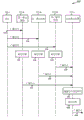
Next, fig. 6 is a call flow diagram illustrating a wireless communication system 600 configured for peer-to-peer or device-to-device location services, in accordance with various embodiments. In some embodiments, the system includes a base station 105-e, which may illustrate aspects of the base station 105 such as described with reference to fig. 1, 2, and 5. The system 600 may include a mobile landmark device 115-m and a target mobile device 115-n, which may illustrate aspects of the mobile device 115 such as described with reference to fig. 1, 2, 3A, 3B, 4, and 5.
The base station 105-e may transmit 610 a signal, e.g., a broadcast, containing a reference signal. The mobile device 115-m may determine 620 its location based at least in part on the received reference signals. The mobile landmark devices 115-m may each transmit 630, for example, a broadcast signal containing reference signals and/or information related to its location. The target mobile device 115-n may receive the broadcast signal and measure 640 the time of arrival of the reference signal relative to the internal clock. The target mobile device 115-n may determine 650 its position via a TDOA method based at least in part on the plurality of measured time of arrival signals and information related to the location of the mobile landmark device 115-m. The target mobile devices 115-n may become mobile landmark devices and transmit 660, e.g., a broadcast signal, containing reference signals and/or information related to their locations for use by neighboring target mobile devices to determine their locations.
Fig. 7 depicts a flow diagram of a method 700 of communication within a wireless communication system, in accordance with various embodiments. The method 700 may be implemented by the mobile device 115 of fig. 1, 2, 3A, 3B, 4, 5, and 6.
At block 710, the method may include receiving a broadcast including a reference signal from each of a plurality of mobile landmark devices. In various embodiments, the operations of block 710 are performed by the receiver module 310 of fig. 3A and 3B, the receiver module 415 of fig. 4, the location module 330 of fig. 3A, 3B, or 4, and/or the landmark determination module 340 of fig. 3B.
In some embodiments, at least one of the plurality of mobile landmark devices is in an operational mode. Additionally or alternatively, at least one of the plurality of mobile landmark devices may include a battery to power the operation. At least one of the plurality of mobile landmark devices may be attached to the air interface. In some cases, the determined position is an absolute position. Each of the plurality of received reference signals may comprise a transmission time.
At block 720, the method may include identifying location information from each of a plurality of mobile landmark devices. In various embodiments, the operations of block 720 are performed by the location module 330 of fig. 3A, 3B, or 4 and/or the landmark determination module 340 of fig. 3B.
In some cases, at block 730, the method includes determining a position based at least in part on the plurality of received reference signals and the plurality of position information. In various embodiments, the operations of block 730 are performed by the location module 330 of fig. 3A, 3B, or 4, the landmark determination module 340 of fig. 3B, and/or the target determination module 350 of fig. 3B.
Fig. 8 depicts a flow diagram of a method 800 of communication within a wireless communication system, in accordance with various embodiments. Method 800 may be an example of method 700, and it may be implemented by mobile device 115 of fig. 1, 2, 3A, 3B, 4, 5, and 6.
At block 810, the method may include receiving a broadcast including a reference signal from each of a plurality of mobile landmark devices. In various embodiments, the operations of block 810 are performed by the receiver module 310 of fig. 3A and 3B, the receiver module 415 of fig. 4, the location module 330 of fig. 3A, 3B, or 4, and/or the landmark determination module 340 of fig. 3B.
At block 820, the method may include identifying location information from each of a plurality of mobile landmark devices. In various embodiments, the operations of block 820 are performed by the location module 330 of fig. 3A, 3B, or 4 and/or the landmark determination module 340 of fig. 3B.
In some cases, at block 830, the method includes determining a position based at least in part on the plurality of received reference signals and the plurality of position information. In various embodiments, the operations of block 830 are performed by the location module 330 of fig. 3A, 3B, or 4, the landmark determination module 340 of fig. 3B, and/or the target determination module 350 of fig. 3B.
At block 840, the method may include broadcasting an outbound reference signal and location-related information based at least in part on the determined location. In various embodiments, the operations of block 840 are performed by the location module 330 of fig. 3A, 3B, or 4, the landmark determination module 340 of fig. 3B, the goal determination module 350 of fig. 3B, the transmitter module 320 of fig. 3A or 3B, and/or the transmitter module 415 of fig. 4. In some embodiments, the broadcasting occurs via an air interface.
Fig. 9 depicts a flow diagram of a method 900 of communication within a wireless communication system, in accordance with various embodiments. Method 900 may be an example of methods 700 and/or 800, and it may be implemented by mobile device 115 of fig. 1, 2, 3A, 3B, 4, 5, and 6.
At block 910, the method may include receiving a broadcast including a reference signal from each of a plurality of mobile landmark devices. In various embodiments, the operations of block 910 are performed by the receiver module 310 of fig. 3A and 3B, the receiver module 415 of fig. 4, the location module 330 of fig. 3A, 3B, or 4, and/or the landmark determination module 340 of fig. 3B.
At block 920, the method may include identifying location information from each of a plurality of mobile landmark devices. In various embodiments, the operations of block 920 are performed by the location module 330 of fig. 3A, 3B, or 4 and/or the landmark determination module 340 of fig. 3B.
In some cases, at block 930, the method includes synchronizing an internal clock based at least in part on the received plurality of reference signals or the plurality of identified location information. In various embodiments, the operations of block 930 are performed by the location module 330 of fig. 3A, 3B, or 4, the landmark determination module 340 of fig. 3B, and/or the goal determination module 350 of fig. 3B.
At block 940, the method includes measuring time of arrival for at least two of the plurality of received reference signals. In various embodiments, the operations of block 940 are performed by the location module 330 of fig. 3A, 3B, or 4 and/or the landmark determination module 340 of fig. 3B.
At block 950, the method may include determining a location based at least in part on the plurality of received reference signals and the plurality of location information. In various embodiments, the operations of block 950 are performed by the location module 330 of fig. 3A, 3B, or 4, the landmark determination module 340 of fig. 3B, and/or the target determination module 350 of fig. 3B.
In some embodiments, determining the location includes calculating a time difference of arrival based on the at least two measured times of arrival, and determining the location based at least in part on the calculated time difference of arrival and the plurality of location information. In some cases, determining a location involves performing triangulation and/or multilateration based, at least in part, on the at least two measured times of arrival and the identified location information for each of the plurality of mobile landmark devices.
At block 960, the method may include broadcasting an outbound reference signal and location-related information based at least in part on the determined location. In various embodiments, the operations of block 960 are performed by the location module 330 of fig. 3A, 3B, or 4, the landmark determination module 340 of fig. 3B, the goal determination module 350 of fig. 3B, the transmitter module 320 of fig. 3A or 3B, and/or the transmitter module 415 of fig. 4.
Those skilled in the art will recognize that methods 700, 800, and 900 are example implementations of the tools and techniques described herein. The method may be performed in more or fewer steps; and the methods may be performed in an order other than the indicated order.
The techniques described herein may be used for various wireless communication systems such as CDMA, TDMA, FDMA, OFDMA, SC-FDMA and other systems. The terms "network" and "system" are often used interchangeably. A CDMA system may implement a radio technology such as CDMA2000, Universal Terrestrial Radio Access (UTRA), and so on. CDMA2000 covers IS-2000, IS-95 and IS-856 standards. IS-2000 releases 0 and A are commonly referred to as CDMA20001X, 1X, etc. IS-856(TIA-856) IS commonly referred to as CDMA20001xEV-DO, High Rate Packet Data (HRPD), etc. UTRA includes wideband CDMA (wcdma) and other variations of CDMA. A TDMA system may implement a radio technology such as global system for mobile communications (GSM). The OFDMA system may implement radio technologies such as Ultra Mobile Broadband (UMB), evolved UTRA (E-UTRA), IEEE 802.11(Wi-Fi), IEEE 802.16(WiMAX), IEEE 802.20, flash OFDM, etc. UTRA and E-UTRA are parts of the Universal Mobile Telecommunications System (UMTS). 3GPP Long Term Evolution (LTE) and LTE advanced (LTE-A) are new versions of UMTS that use E-UTRA. UTRA, E-UTRA, UMTS, LTE-A and GSM are described in the literature from an organization named "third Generation partnership project" (3 GPP). CDMA2000 and UMB are described in literature from an organization named "third generation partnership project 2" (3GPP 2). The techniques described herein may be used for the systems and radio technologies mentioned above, as well as other systems and radio technologies. However, the description above describes an LTE system for purposes of example, and LTE terminology is used in much of the description above, but the techniques are applicable beyond LTE applications.
The embodiments set forth above in connection with the attached drawings describe exemplary embodiments and are not intended to represent the only embodiments which may be practiced or are within the scope of the claims. The detailed description contains specific details for the purpose of providing an understanding of the described technology. However, the techniques may be practiced without these specific details. In some instances, well-known structures and devices are shown in block diagram form in order to avoid obscuring the concepts of the described embodiments.
Information and signals may be represented using any of a variety of different technologies and techniques. For example, data, instructions, commands, information, signals, bits, symbols, and chips that may be referenced throughout the above description may be represented by voltages, currents, electromagnetic waves, magnetic fields or particles, optical fields or particles, or any combination thereof.
The various illustrative blocks and modules described in connection with the disclosure herein may be implemented or performed with a general purpose processor, a Digital Signal Processor (DSP), an Application Specific Integrated Circuit (ASIC), a Field Programmable Gate Array (FPGA) or other programmable logic device, discrete gate or transistor logic, discrete hardware components, or any combination thereof designed to perform the functions described herein. A general purpose processor may be a microprocessor, but in the alternative, the processor may be any conventional processor, controller, microcontroller, or state machine. A processor may also be implemented as a combination of computing devices, e.g., a combination of a DSP and a microprocessor, a plurality of microprocessors, one or more microprocessors in conjunction with a DSP core, or any other such configuration.
The functions described herein may be implemented in hardware, software executed by a processor, firmware, or any combination thereof. If implemented in software executed by a processor, the functions may be stored on or transmitted over as one or more instructions or code on a computer-readable medium. Other examples and implementations are within the scope and spirit of the invention and the following claims. For example, due to the nature of software, the functions described above may be implemented using software executed by a processor, hardware, firmware, hardwired, or a combination of any of these. Features implementing functions may also be physically located at various locations, including being distributed such that portions of functions are implemented at different physical locations. Also, as used herein (including in the claims), "or" when used in a list of items ending in "at least one of indicates a disjunctive list such that, for example, a listing of" at least one of A, B or C "refers to a or B or C or AB or AC or BC or ABC (i.e., a and B and C).
Computer-readable media includes both computer storage media and communication media including any medium that facilitates transfer of a computer program from one place to another. A storage media may be any available media that can be accessed by a general purpose or special purpose computer. By way of example, and not limitation, computer-readable media can comprise RAM, ROM, EEPROM, CD-ROM or other optical disk storage, magnetic disk storage or other magnetic storage devices, or any other medium that can be used to carry or store desired program code means in the form of instructions or data structures and that can be accessed by a general-purpose or special-purpose computer, or a general-purpose or special-purpose processor. Also, any connection is properly termed a computer-readable medium. For example, if the software is transmitted from a website, server, or other remote source using a coaxial cable, fiber optic cable, twisted pair, Digital Subscriber Line (DSL), or wireless technologies such as infrared, radio, and microwave, then the coaxial cable, fiber optic cable, twisted pair, DSL, or wireless technologies such as infrared, radio, and microwave are included in the definition of medium. Disk and disc, as used herein, includes Compact Disc (CD), laser disc, optical disc, Digital Versatile Disc (DVD), floppy disk and blu-ray disc where disks usually reproduce data magnetically, while discs reproduce data optically with lasers. Combinations of the above are also included within the scope of computer-readable media.
The previous description of the disclosure is provided to enable any person skilled in the art to make or use the disclosure. Various modifications to the disclosure will be readily apparent to those skilled in the art, and the generic principles defined herein may be applied to other variations without departing from the spirit or scope of the disclosure. Throughout this disclosure, the terms "example" or "exemplary" indicate an example or instance, and do not imply or require any preference for the mentioned example. Thus, the disclosure is not intended to be limited to the examples and designs described herein but is to be accorded the widest scope consistent with the principles and novel features disclosed herein.
Claims (30)
1. A method of communicating within a wireless communication network, the method comprising:
receiving, at a User Equipment (UE), a broadcast comprising a reference signal from each of a plurality of mobile landmark devices;
identifying location information from each of the plurality of mobile landmark devices; and
determining a location of the UE based at least in part on the plurality of received reference signals and the plurality of location information,
wherein the UE operates in a plurality of modes including a target mode and a landmark mode and transitions between the target mode and the landmark mode based on information available for use by the UE,
wherein if the UE is in the target mode, the UE attempts to determine its position based at least in part on signals received from another mobile device and/or from a network, and if the UE is in the landmark mode, the UE broadcasts a signal including its position such that other mobile devices receive the signal and determine their respective positions based at least in part on the received signal.
2. The method of claim 1, further comprising:
measuring time of arrival for at least two of the plurality of received reference signals.
3. The method of claim 2, wherein determining the location of the UE comprises:
calculating a time difference of arrival based on the at least two measured times of arrival; and
determining a location of the UE based at least in part on the calculated time difference of arrival and the plurality of location information.
4. The method of claim 2, wherein determining a location of the UE comprises performing multilateration based, at least in part, on the at least two measured times of arrival and identified location information for each of the plurality of mobile landmark devices.
5. The method of claim 1, further comprising:
broadcasting an outbound reference signal and location-related information based at least in part on the determined location of the UE.
6. The method of claim 5, wherein the broadcasting occurs over an air interface.
7. The method of claim 1, further comprising:
synchronizing an internal clock based at least in part on the received plurality of reference signals or the plurality of identified location information.
8. The method of claim 1, wherein at least one of the plurality of mobile landmark devices is in an operational mode.
9. The method of claim 1, wherein at least one of the plurality of mobile landmark devices includes a battery that is powered for operation.
10. The method of claim 1, wherein at least one of the plurality of mobile landmark devices is attached to an air interface.
11. The method of claim 1, wherein the determined location of the UE is an absolute location.
12. The method of claim 1, wherein each of the plurality of received reference signals comprises a time of transmission.
13. A system for wireless communication, comprising:
means for receiving, at a User Equipment (UE), a broadcast comprising a reference signal from each of a plurality of mobile landmark devices;
means for identifying location information from each of the plurality of mobile landmark devices; and
means for determining a location of the UE based at least in part on the plurality of received reference signals and the plurality of location information,
wherein the UE operates in a plurality of modes including a target mode and a landmark mode and transitions between the target mode and the landmark mode based on information available for use by the UE,
wherein if the UE is in the target mode, the UE attempts to determine its position based at least in part on signals received from another mobile device and/or from a network, and if the UE is in the landmark mode, the UE broadcasts a signal including its position such that other mobile devices receive the signal and determine their respective positions based at least in part on the received signal.
14. The system of claim 13, further comprising:
means for measuring time of arrival for at least two of the plurality of received reference signals.
15. The system of claim 14, wherein the means for determining the location of the UE comprises:
means for calculating a time difference of arrival based on the at least two measured times of arrival; and
means for determining a location of the UE based at least in part on the calculated time difference of arrival and the plurality of location information.
16. The system of claim 14, wherein the means for determining a location of the UE comprises means for performing multilateration based, at least in part, on the at least two measured times of arrival and identified location information for each of the plurality of mobile landmark devices.
17. The system of claim 13, further comprising:
means for broadcasting outbound reference signals and location-related information based at least in part on the determined location of the UE.
18. The system of claim 13, further comprising:
means for synchronizing an internal clock based at least in part on the received plurality of reference signals or the plurality of identified location information.
19. The system of claim 13, wherein at least one of the plurality of mobile landmark devices is in an operational mode.
20. The system of claim 13, wherein the determined location of the UE is an absolute location.
21. The system of claim 13, wherein each of the plurality of received reference signals comprises a time of transmission.
22. An apparatus for wireless communication, comprising:
a processor;
a memory in electronic communication with the processor; and
instructions stored in the memory, the instructions executable by the processor to:
receiving, at a User Equipment (UE), a broadcast comprising a reference signal from each of a plurality of mobile landmark devices;
identifying location information from each of the plurality of mobile landmark devices; and
determining a location of the UE based at least in part on the plurality of received reference signals and the plurality of location information,
wherein the UE operates in a plurality of modes including a target mode and a landmark mode and transitions between the target mode and the landmark mode based on information available for use by the UE,
wherein if the UE is in the target mode, the UE attempts to determine its position based at least in part on signals received from another mobile device and/or from a network, and if the UE is in the landmark mode, the UE broadcasts a signal including its position such that other mobile devices receive the signal and determine their respective positions based at least in part on the received signal.
23. The apparatus of claim 22, wherein the instructions are executable by the processor to:
measuring time of arrival for at least two of the plurality of received reference signals.
24. The apparatus of claim 23, wherein the instructions to determine a location of the UE are executable by the processor to:
calculating a time difference of arrival based on the at least two measured times of arrival; and
determining a location of the UE based at least in part on the calculated time difference of arrival and the plurality of location information.
25. The apparatus of claim 22, wherein the instructions are executable by the processor to:
broadcasting an outbound reference signal and location-related information based at least in part on the determined location of the UE.
26. The apparatus of claim 22, wherein the instructions are executable by the processor to:
synchronizing an internal clock based at least in part on the received plurality of reference signals or the plurality of identified location information.
27. A non-transitory computer-readable medium storing instructions for wireless communication, the instructions executable to:
receiving, at a User Equipment (UE), a broadcast comprising a reference signal from each of a plurality of mobile landmark devices;
identifying location information from each of the plurality of mobile landmark devices; and
determining a location of the UE based at least in part on the plurality of received reference signals and the plurality of location information,
wherein the UE operates in a plurality of modes including a target mode and a landmark mode and transitions between the target mode and the landmark mode based on information available for use by the UE,
wherein if the UE is in the target mode, the UE attempts to determine its position based at least in part on signals received from another mobile device and/or from a network, and if the UE is in the landmark mode, the UE broadcasts a signal including its position such that other mobile devices receive the signal and determine their respective positions based at least in part on the received signal.
28. The non-transitory computer-readable medium of claim 27, wherein the instructions to determine the location of the UE are executable to:
measuring time of arrival for at least two of the plurality of received reference signals;
calculating a time difference of arrival based on the at least two measured times of arrival; and
determining a location of the UE based at least in part on the calculated time difference of arrival and the plurality of location information.
29. The non-transitory computer-readable medium of claim 27, wherein the instructions are executable to:
broadcasting an outbound reference signal and location-related information based at least in part on the determined location of the UE.
30. The non-transitory computer-readable medium of claim 27, wherein the instructions are executable to:
synchronizing an internal clock based at least in part on the received plurality of reference signals or the plurality of identified location information.
Applications Claiming Priority (3)
| Application Number | Priority Date | Filing Date | Title |
|---|---|---|---|
| US14/105,087 US9638783B2 (en) | 2013-12-12 | 2013-12-12 | Broadcast-based positioning for device-to-device proximity services |
| US14/105,087 | 2013-12-12 | ||
| PCT/US2014/067953 WO2015088812A2 (en) | 2013-12-12 | 2014-12-01 | Broadcast-based positioning for device-to-device proximity services |
Publications (2)
| Publication Number | Publication Date |
|---|---|
| CN105794235A CN105794235A (en) | 2016-07-20 |
| CN105794235B true CN105794235B (en) | 2020-04-10 |
Family
ID=52144899
Family Applications (1)
| Application Number | Title | Priority Date | Filing Date |
|---|---|---|---|
| CN201480065708.3A Active CN105794235B (en) | 2013-12-12 | 2014-12-01 | Method, system and device for wireless communication |
Country Status (8)
| Country | Link |
|---|---|
| US (1) | US9638783B2 (en) |
| EP (1) | EP3081018B1 (en) |
| JP (1) | JP6495287B2 (en) |
| KR (1) | KR101775299B1 (en) |
| CN (1) | CN105794235B (en) |
| BR (1) | BR112016013178B1 (en) |
| ES (1) | ES2869927T3 (en) |
| WO (1) | WO2015088812A2 (en) |
Families Citing this family (10)
| Publication number | Priority date | Publication date | Assignee | Title |
|---|---|---|---|---|
| US9638783B2 (en) * | 2013-12-12 | 2017-05-02 | Qualcomm Incorporated | Broadcast-based positioning for device-to-device proximity services |
| MX2018000026A (en) | 2015-07-08 | 2018-03-15 | Ericsson Telefon Ab L M | Location information in communications networks. |
| CN107466018B (en) * | 2016-06-02 | 2021-08-24 | 海能达通信股份有限公司 | Data transmission method of terminal equipment and terminal equipment |
| DE102016007195A1 (en) | 2016-06-14 | 2017-12-14 | Audi Ag | Control device and method for determining an own position of a mobile terminal and motor vehicle |
| US10477395B2 (en) * | 2017-11-06 | 2019-11-12 | Fujitsu Limited | Open public internet-of-things systems and methods |
| US11181387B2 (en) | 2018-09-27 | 2021-11-23 | International Business Machines Corporation | Dynamic routing system |
| EP4070120A4 (en) * | 2019-12-03 | 2024-01-03 | Locata Corp | Methods and apparatus for improving the resilience of a positioning network |
| KR20210079800A (en) | 2019-12-20 | 2021-06-30 | 삼성전자주식회사 | Electronic device and controlling method of electronic device |
| WO2021141404A1 (en) * | 2020-01-07 | 2021-07-15 | 엘지전자 주식회사 | Method and apparatus for performing sidelink-based positioning |
| US11294024B2 (en) * | 2020-03-10 | 2022-04-05 | Deeyook Location Technologies Ltd. | System, apparatus, and/or method for determining a time of flight for one or more receivers and transmitters |
Citations (5)
| Publication number | Priority date | Publication date | Assignee | Title |
|---|---|---|---|---|
| CN102714781A (en) * | 2010-01-08 | 2012-10-03 | 高通股份有限公司 | Method and apparatus for positioning of devices in a wireless network |
| CN103155457A (en) * | 2010-10-17 | 2013-06-12 | Lg电子株式会社 | Method and base station for transmitting location measurement reference signal, and method and user equipment for receiving location measurement reference signal |
| CN103339522A (en) * | 2010-12-15 | 2013-10-02 | 谷歌公司 | Peer-to-peer location service |
| CN103348747A (en) * | 2011-01-03 | 2013-10-09 | 高通股份有限公司 | Target positioning within a mobile structure |
| CN105794235A (en) * | 2013-12-12 | 2016-07-20 | 高通股份有限公司 | Broadcast-based positioning for device-to-device proximity services |
Family Cites Families (16)
| Publication number | Priority date | Publication date | Assignee | Title |
|---|---|---|---|---|
| US7129891B2 (en) | 2003-11-21 | 2006-10-31 | Xerox Corporation | Method for determining proximity of devices in a wireless network |
| GB0401767D0 (en) * | 2004-01-27 | 2004-03-03 | Koninkl Philips Electronics Nv | Positioning systems |
| CA2554417C (en) * | 2004-02-17 | 2010-11-23 | Jadi, Inc. | Ultra wide band navigation system with mobile base stations |
| US7411937B2 (en) * | 2005-08-09 | 2008-08-12 | Agilent Technologies, Inc. | Time synchronization system and method for synchronizing locating units within a communication system using a known external signal |
| JP2008306532A (en) * | 2007-06-08 | 2008-12-18 | Kddi R & D Laboratories Inc | Mobile terminal, positioning system and positioning method using the same, and its program |
| KR101418357B1 (en) * | 2007-07-09 | 2014-07-14 | 삼성전자주식회사 | Method and apparatus for peer to peer connection in wireless communication system |
| US8605625B2 (en) * | 2009-04-02 | 2013-12-10 | Qualcomm Incorporated | Methods and apparatus for peer discovery in a communications system |
| US8699409B2 (en) * | 2009-04-08 | 2014-04-15 | Qualcomm Incorporated | Methods and apparatuses for providing peer-to-peer positioning in wireless networks |
| WO2010138972A2 (en) * | 2009-05-29 | 2010-12-02 | Abacast, Inc. | Selective access of multi-rate data from a server and/or peer |
| US20100323717A1 (en) | 2009-06-23 | 2010-12-23 | Qualcomm Incorporated | Method and apparatus for facilitating proximity detection in a wireless network |
| US8467309B2 (en) * | 2009-12-23 | 2013-06-18 | Verizon Patent And Licensing Inc. | Packet based location provisioning in wireless networks |
| US8862146B2 (en) * | 2010-10-04 | 2014-10-14 | Blackberry Limited | Method, device and system for enhancing location information |
| US9482734B2 (en) * | 2011-03-28 | 2016-11-01 | Qualcomm Incorporated | Methods and apparatus for triggering cooperative positioning or learning in a wireless network |
| US8938257B2 (en) | 2011-08-19 | 2015-01-20 | Qualcomm, Incorporated | Logo detection for indoor positioning |
| EP2763477A4 (en) * | 2011-09-30 | 2016-03-23 | Mitsubishi Electric Corp | Radio communication system, mobile terminal device, base station device, and management device |
| US9098177B2 (en) * | 2012-12-13 | 2015-08-04 | Google Technology Holdings LLC | Apparatus and methods for facilitating context handoff between devices in a cloud based wireless personal area network |
-
2013
- 2013-12-12 US US14/105,087 patent/US9638783B2/en active Active
-
2014
- 2014-12-01 JP JP2016538554A patent/JP6495287B2/en active Active
- 2014-12-01 KR KR1020167015552A patent/KR101775299B1/en active IP Right Grant
- 2014-12-01 BR BR112016013178-9A patent/BR112016013178B1/en active IP Right Grant
- 2014-12-01 WO PCT/US2014/067953 patent/WO2015088812A2/en active Application Filing
- 2014-12-01 ES ES14816529T patent/ES2869927T3/en active Active
- 2014-12-01 CN CN201480065708.3A patent/CN105794235B/en active Active
- 2014-12-01 EP EP14816529.3A patent/EP3081018B1/en active Active
Patent Citations (5)
| Publication number | Priority date | Publication date | Assignee | Title |
|---|---|---|---|---|
| CN102714781A (en) * | 2010-01-08 | 2012-10-03 | 高通股份有限公司 | Method and apparatus for positioning of devices in a wireless network |
| CN103155457A (en) * | 2010-10-17 | 2013-06-12 | Lg电子株式会社 | Method and base station for transmitting location measurement reference signal, and method and user equipment for receiving location measurement reference signal |
| CN103339522A (en) * | 2010-12-15 | 2013-10-02 | 谷歌公司 | Peer-to-peer location service |
| CN103348747A (en) * | 2011-01-03 | 2013-10-09 | 高通股份有限公司 | Target positioning within a mobile structure |
| CN105794235A (en) * | 2013-12-12 | 2016-07-20 | 高通股份有限公司 | Broadcast-based positioning for device-to-device proximity services |
Also Published As
| Publication number | Publication date |
|---|---|
| EP3081018A2 (en) | 2016-10-19 |
| US9638783B2 (en) | 2017-05-02 |
| WO2015088812A2 (en) | 2015-06-18 |
| JP6495287B2 (en) | 2019-04-03 |
| BR112016013178A2 (en) | 2017-08-08 |
| KR101775299B1 (en) | 2017-09-05 |
| BR112016013178B1 (en) | 2022-12-20 |
| WO2015088812A3 (en) | 2015-08-06 |
| EP3081018B1 (en) | 2021-04-28 |
| CN105794235A (en) | 2016-07-20 |
| KR20160096614A (en) | 2016-08-16 |
| ES2869927T3 (en) | 2021-10-26 |
| US20150168532A1 (en) | 2015-06-18 |
| JP2017505426A (en) | 2017-02-16 |
Similar Documents
| Publication | Publication Date | Title |
|---|---|---|
| CN105794235B (en) | Method, system and device for wireless communication | |
| CN110326331B (en) | Method and apparatus for signaling public land mobile network identifiers over a shared radio frequency spectrum band | |
| US9986373B2 (en) | LTE-A systems and method of DRS based positioning | |
| CN111034094B (en) | Method, apparatus, device and medium for wireless communication | |
| US9967752B2 (en) | Transmission and reception of common channel in an unlicensed or shared spectrum | |
| CN109314867B (en) | Enhanced neighbor relation and physical cell identifier confusion detection | |
| JP6820976B2 (en) | Cell sync and sync cell indication | |
| US20190313272A1 (en) | Techniques in system frame number (sfn) and frame timing difference measurements in new radio (nr) | |
| EP3183923B1 (en) | Wideband ranging in cellular using unlicensed radio frequency spectrum band | |
| TWI454159B (en) | Method and apparatus for enhancement of cell id-based position determination in td-scdma multimode terminals | |
| US9825745B2 (en) | Common reference signal phase discontinuity and sequence initialization | |
| EP3031256B1 (en) | Timing synchronization for device-to-device discovery for asynchronous lte deployments | |
| WO2015127223A1 (en) | User equipment, computer readable medium, and method to determine the mobility of user equipment in a long- term evolution network | |
| CN110547012B (en) | Method and apparatus for processing signals | |
| US20150257065A1 (en) | Method and Apparatus for Enabling a User Equipment to Use Cells Having Different Frequencies | |
| WO2022021340A1 (en) | Techniques for cross link interference measurement in wireless communications | |
| EP3020234B1 (en) | Using short range discovery to predict the agc setting for long range discovery | |
| US20150043370A1 (en) | Inter-Cell Interference Detection for Inter Portable Long Term Evolution Local Area Network Interference |
Legal Events
| Date | Code | Title | Description |
|---|---|---|---|
| C06 | Publication | ||
| PB01 | Publication | ||
| C10 | Entry into substantive examination | ||
| SE01 | Entry into force of request for substantive examination | ||
| GR01 | Patent grant | ||
| GR01 | Patent grant |