CN105561443B - Retractable needle type injector - Google Patents
Retractable needle type injector Download PDFInfo
- Publication number
- CN105561443B CN105561443B CN201510726904.7A CN201510726904A CN105561443B CN 105561443 B CN105561443 B CN 105561443B CN 201510726904 A CN201510726904 A CN 201510726904A CN 105561443 B CN105561443 B CN 105561443B
- Authority
- CN
- China
- Prior art keywords
- needle
- plunger
- syringe
- needle hub
- propellant
- Prior art date
- Legal status (The legal status is an assumption and is not a legal conclusion. Google has not performed a legal analysis and makes no representation as to the accuracy of the status listed.)
- Active
Links
Images


Classifications
-
- A—HUMAN NECESSITIES
- A61—MEDICAL OR VETERINARY SCIENCE; HYGIENE
- A61M—DEVICES FOR INTRODUCING MEDIA INTO, OR ONTO, THE BODY; DEVICES FOR TRANSDUCING BODY MEDIA OR FOR TAKING MEDIA FROM THE BODY; DEVICES FOR PRODUCING OR ENDING SLEEP OR STUPOR
- A61M5/00—Devices for bringing media into the body in a subcutaneous, intra-vascular or intramuscular way; Accessories therefor, e.g. filling or cleaning devices, arm-rests
- A61M5/178—Syringes
- A61M5/31—Details
- A61M5/32—Needles; Details of needles pertaining to their connection with syringe or hub; Accessories for bringing the needle into, or holding the needle on, the body; Devices for protection of needles
- A61M5/3205—Apparatus for removing or disposing of used needles or syringes, e.g. containers; Means for protection against accidental injuries from used needles
- A61M5/321—Means for protection against accidental injuries by used needles
- A61M5/322—Retractable needles, i.e. disconnected from and withdrawn into the syringe barrel by the piston
- A61M5/3234—Fully automatic needle retraction, i.e. in which triggering of the needle does not require a deliberate action by the user
-
- A—HUMAN NECESSITIES
- A61—MEDICAL OR VETERINARY SCIENCE; HYGIENE
- A61M—DEVICES FOR INTRODUCING MEDIA INTO, OR ONTO, THE BODY; DEVICES FOR TRANSDUCING BODY MEDIA OR FOR TAKING MEDIA FROM THE BODY; DEVICES FOR PRODUCING OR ENDING SLEEP OR STUPOR
- A61M5/00—Devices for bringing media into the body in a subcutaneous, intra-vascular or intramuscular way; Accessories therefor, e.g. filling or cleaning devices, arm-rests
- A61M5/178—Syringes
- A61M5/20—Automatic syringes, e.g. with automatically actuated piston rod, with automatic needle injection, filling automatically
- A61M5/2046—Media being expelled from injector by gas generation, e.g. explosive charge
-
- A—HUMAN NECESSITIES
- A61—MEDICAL OR VETERINARY SCIENCE; HYGIENE
- A61M—DEVICES FOR INTRODUCING MEDIA INTO, OR ONTO, THE BODY; DEVICES FOR TRANSDUCING BODY MEDIA OR FOR TAKING MEDIA FROM THE BODY; DEVICES FOR PRODUCING OR ENDING SLEEP OR STUPOR
- A61M5/00—Devices for bringing media into the body in a subcutaneous, intra-vascular or intramuscular way; Accessories therefor, e.g. filling or cleaning devices, arm-rests
- A61M5/178—Syringes
- A61M5/31—Details
- A61M5/32—Needles; Details of needles pertaining to their connection with syringe or hub; Accessories for bringing the needle into, or holding the needle on, the body; Devices for protection of needles
- A61M5/3205—Apparatus for removing or disposing of used needles or syringes, e.g. containers; Means for protection against accidental injuries from used needles
- A61M5/321—Means for protection against accidental injuries by used needles
- A61M5/322—Retractable needles, i.e. disconnected from and withdrawn into the syringe barrel by the piston
- A61M5/3221—Constructional features thereof, e.g. to improve manipulation or functioning
-
- A—HUMAN NECESSITIES
- A61—MEDICAL OR VETERINARY SCIENCE; HYGIENE
- A61M—DEVICES FOR INTRODUCING MEDIA INTO, OR ONTO, THE BODY; DEVICES FOR TRANSDUCING BODY MEDIA OR FOR TAKING MEDIA FROM THE BODY; DEVICES FOR PRODUCING OR ENDING SLEEP OR STUPOR
- A61M5/00—Devices for bringing media into the body in a subcutaneous, intra-vascular or intramuscular way; Accessories therefor, e.g. filling or cleaning devices, arm-rests
- A61M5/178—Syringes
- A61M5/31—Details
- A61M5/32—Needles; Details of needles pertaining to their connection with syringe or hub; Accessories for bringing the needle into, or holding the needle on, the body; Devices for protection of needles
- A61M5/3293—Needles; Details of needles pertaining to their connection with syringe or hub; Accessories for bringing the needle into, or holding the needle on, the body; Devices for protection of needles characterised by features of the needle hub
-
- A—HUMAN NECESSITIES
- A61—MEDICAL OR VETERINARY SCIENCE; HYGIENE
- A61M—DEVICES FOR INTRODUCING MEDIA INTO, OR ONTO, THE BODY; DEVICES FOR TRANSDUCING BODY MEDIA OR FOR TAKING MEDIA FROM THE BODY; DEVICES FOR PRODUCING OR ENDING SLEEP OR STUPOR
- A61M5/00—Devices for bringing media into the body in a subcutaneous, intra-vascular or intramuscular way; Accessories therefor, e.g. filling or cleaning devices, arm-rests
- A61M5/178—Syringes
- A61M5/31—Details
- A61M5/32—Needles; Details of needles pertaining to their connection with syringe or hub; Accessories for bringing the needle into, or holding the needle on, the body; Devices for protection of needles
- A61M5/3205—Apparatus for removing or disposing of used needles or syringes, e.g. containers; Means for protection against accidental injuries from used needles
- A61M5/321—Means for protection against accidental injuries by used needles
- A61M5/322—Retractable needles, i.e. disconnected from and withdrawn into the syringe barrel by the piston
- A61M5/3221—Constructional features thereof, e.g. to improve manipulation or functioning
- A61M2005/3231—Proximal end of needle captured or embedded inside piston head, e.g. by friction or hooks
-
- A—HUMAN NECESSITIES
- A61—MEDICAL OR VETERINARY SCIENCE; HYGIENE
- A61M—DEVICES FOR INTRODUCING MEDIA INTO, OR ONTO, THE BODY; DEVICES FOR TRANSDUCING BODY MEDIA OR FOR TAKING MEDIA FROM THE BODY; DEVICES FOR PRODUCING OR ENDING SLEEP OR STUPOR
- A61M5/00—Devices for bringing media into the body in a subcutaneous, intra-vascular or intramuscular way; Accessories therefor, e.g. filling or cleaning devices, arm-rests
- A61M5/178—Syringes
- A61M5/31—Details
- A61M5/32—Needles; Details of needles pertaining to their connection with syringe or hub; Accessories for bringing the needle into, or holding the needle on, the body; Devices for protection of needles
- A61M5/3205—Apparatus for removing or disposing of used needles or syringes, e.g. containers; Means for protection against accidental injuries from used needles
- A61M5/321—Means for protection against accidental injuries by used needles
- A61M5/322—Retractable needles, i.e. disconnected from and withdrawn into the syringe barrel by the piston
- A61M5/3234—Fully automatic needle retraction, i.e. in which triggering of the needle does not require a deliberate action by the user
- A61M2005/3241—Needle retraction energy is accumulated inside of a hollow plunger rod
- A61M2005/3242—Needle retraction by vacuum
-
- A—HUMAN NECESSITIES
- A61—MEDICAL OR VETERINARY SCIENCE; HYGIENE
- A61M—DEVICES FOR INTRODUCING MEDIA INTO, OR ONTO, THE BODY; DEVICES FOR TRANSDUCING BODY MEDIA OR FOR TAKING MEDIA FROM THE BODY; DEVICES FOR PRODUCING OR ENDING SLEEP OR STUPOR
- A61M5/00—Devices for bringing media into the body in a subcutaneous, intra-vascular or intramuscular way; Accessories therefor, e.g. filling or cleaning devices, arm-rests
- A61M5/50—Devices for bringing media into the body in a subcutaneous, intra-vascular or intramuscular way; Accessories therefor, e.g. filling or cleaning devices, arm-rests having means for preventing re-use, or for indicating if defective, used, tampered with or unsterile
- A61M5/5013—Means for blocking the piston or the fluid passageway to prevent illegal refilling of a syringe
- A61M5/502—Means for blocking the piston or the fluid passageway to prevent illegal refilling of a syringe for blocking the piston
-
- A—HUMAN NECESSITIES
- A61—MEDICAL OR VETERINARY SCIENCE; HYGIENE
- A61M—DEVICES FOR INTRODUCING MEDIA INTO, OR ONTO, THE BODY; DEVICES FOR TRANSDUCING BODY MEDIA OR FOR TAKING MEDIA FROM THE BODY; DEVICES FOR PRODUCING OR ENDING SLEEP OR STUPOR
- A61M5/00—Devices for bringing media into the body in a subcutaneous, intra-vascular or intramuscular way; Accessories therefor, e.g. filling or cleaning devices, arm-rests
- A61M5/50—Devices for bringing media into the body in a subcutaneous, intra-vascular or intramuscular way; Accessories therefor, e.g. filling or cleaning devices, arm-rests having means for preventing re-use, or for indicating if defective, used, tampered with or unsterile
- A61M5/508—Means for preventing re-use by disrupting the piston seal, e.g. by puncturing
Landscapes
- Health & Medical Sciences (AREA)
- Engineering & Computer Science (AREA)
- Hematology (AREA)
- Anesthesiology (AREA)
- Biomedical Technology (AREA)
- Heart & Thoracic Surgery (AREA)
- Vascular Medicine (AREA)
- Life Sciences & Earth Sciences (AREA)
- Animal Behavior & Ethology (AREA)
- General Health & Medical Sciences (AREA)
- Public Health (AREA)
- Veterinary Medicine (AREA)
- Environmental & Geological Engineering (AREA)
- Infusion, Injection, And Reservoir Apparatuses (AREA)
Abstract
A retractable needle injector comprising: a syringe barrel; a plunger slidably disposed within and in sealing engagement with the syringe barrel, the plunger having a retraction cavity defined therein; a needle attached to the distal end of the syringe barrel and in fluid communication with a medicament chamber defined within the syringe barrel distal of the plunger; a needle hub for securing the needle at the distal end of the syringe barrel; a lock tip disposed at the distal end of the plunger, the lock tip sealingly engaging the retraction cavity and initially being secured within the retraction cavity against a loading or injection force applied by a user and being released to slidingly retract within the plunger cavity in response to release of an injection agent upon application of a post-injection force by the user; a propellant release unit disposed at the distal end of the needle hub and containing a propellant; and a puncturing mechanism arranged to puncture the propellant release unit in response to the post-injection force applied by a user thereby driving the retraction assembly to retract within the retraction cavity.
Description
Cross Reference to Related Applications
The present application claims priority and benefit from U.S. provisional patent application 62/073,748 filed on month 31 of 2014 and U.S. patent application 62/105,624 filed on month 20 of 2015, both of which are incorporated herein by reference in their entireties
Technical Field
Some embodiments of the present invention relate to syringes having retractable needles. In some embodiments, the syringe is a pneumatically actuated retractable needle syringe.
Background
It is well known that many dangerous infectious diseases are transmitted by contact with the body fluids of infected persons. After use of the syringe, residual body fluid is likely to remain on or within the needle. Thus, syringes are typically intended for single use only. In order to be safely disposed of after use, the needle of the syringe must be covered to prevent it from accidentally sticking to a person who is collecting the syringe for disposal, for example, thereby releasing the remaining body fluid into the person. Typically, a syringe is provided having a protective cap which may be used to cover the tip of the needle after use of the syringe. However, it sometimes happens that a person attempting to cover the used needle misses the cover and accidentally sticks himself, resulting in possible exposure to infectious diseases.
It would therefore be desirable to provide a syringe in which the needle can be retracted into the syringe after use. The retraction of the needle is accomplished by pneumatic actuation as exemplified by, for example, U.S. patent No.5,868,713 to Klippenstein and U.S. patent No.7,811,259 to Klippenstein, both of which are incorporated herein by reference.
The foregoing examples of related art and limitations related thereto are for illustrative purposes and not intended to be exhaustive. Other limitations of the related art will become apparent to those of skill in the art upon a reading of the specification and a study of the drawings.
Disclosure of Invention
In one aspect, a retractable needle injector is provided. The syringe has a syringe barrel; a plunger slidably disposed within and in sealing engagement with the syringe barrel, the plunger having a retraction cavity defined therein for receiving a needle upon actuation of the retractable needle syringe; a needle attached to the distal end of the syringe barrel and in fluid communication with a medicament chamber defined within the syringe barrel distal of the plunger; a needle hub for a needle secured to the distal end of the syringe barrel, the needle hub initially being secured within the secondary wall against a loading or injection force applied by a user and being separated from the secondary wall in response to a post-injection force applied by a user; a lock tip disposed at a distal end of the plunger, the lock tip sealingly engaging the retraction cavity and initially being secured within the retraction cavity against a loading or injection force applied by a user and being released to slidably retract within the plunger cavity in response to release of an injection when a post-injection force is applied by a user, the lock tip engaging the needle hub in response to the post-injection force to provide a retraction assembly comprising the lock tip, a needle head and the needle; a propellant release unit disposed at the distal end of the needle hub and containing a propellant; and a puncturing mechanism arranged to puncture the propellant release unit in response to the post-injection force applied by a user, thereby driving the retraction assembly to retract within the retraction chamber.
In another aspect, a retractable needle injector having a barrel; a plunger axially slidable within the barrel for drawing medicament into a medicament chamber defined within the barrel and injecting the medicament into a patient, the plunger having a retraction cavity therein; a locking tip engaging the distal end of the plunger within the retraction cavity; a secondary wall initially engaged with the barrel proximate the distal end of the barrel, the secondary wall being movable in a distal direction in response to the post-injection force applied by a user; a needle hub initially secured by the secondary wall, the needle hub cooperating with the locking tip to provide a retraction assembly, the retraction assembly including the locking tip, the needle head and the needle, and the needle hub being separated from the secondary wall in response to a post-injection force applied by a user, the needle extending from the distal end of the barrel, the needle secured to the needle hub, a single propellant release structure disposed at the distal end of the needle hub in the barrel, and a puncturing mechanism movable upon application of the post-injection force by a user to puncture the single propellant release structure thereby driving retraction assembly within the retraction cavity.
In some aspects, the needle hub has a barb and the lock tip is made of a relatively softer material than the barb such that the barb may cooperate with the lock tip to provide a retraction assembly when the post-injection force is applied by a user.
Drawings
Example embodiments are illustrated by reference figures in the accompanying drawings. The embodiments and figures disclosed herein should be considered illustrative and not restrictive.
Fig. 1 is a perspective view of an exemplary embodiment of a retractable needle injector.
Fig. 2 is a cross-sectional view of the embodiment shown in fig. 1.
Fig. 3 is a perspective view showing an alignment tab on an exemplary embodiment of a needle guide.
Fig. 4 is a perspective view illustrating a groove formed in an exemplary embodiment of a needle cover.
Fig. 5 shows an exemplary embodiment of a propellant release unit.
Fig. 6 shows a cross-sectional view of an exemplary embodiment of the propellant release unit depicted in fig. 5.
Fig. 7 is a perspective view of a needle hub according to an example embodiment.
Fig. 8 is a cross-sectional view of the needle hub depicted in fig. 7.
Fig. 9A is a perspective view of an auxiliary wall according to an example embodiment.
Fig. 9B is a cross-sectional view of an auxiliary wall according to an example embodiment.
Fig. 9C is an end view of an exemplary embodiment of a syringe barrel showing the configuration of an exemplary embodiment of the secondary wall retention feature.
Fig. 9D is a partial cross-sectional view of an exemplary embodiment of a syringe barrel illustrating the configuration of an exemplary embodiment of the secondary wall retention feature.
FIG. 10 is a partial cross-sectional view illustrating components of an example embodiment.
FIG. 11A is a perspective view of a lock tip according to an example embodiment.
FIG. 11B is a perspective view of a second exemplary embodiment of a lock tip
FIG. 11C is a cross-sectional view of the exemplary embodiment of the locking tip shown in FIG. 11A.
FIG. 12 illustrates a partial perspective view of a plunger according to an example embodiment.
Fig. 13 is a perspective view illustrating engagement of a plunger locking feature that locks the plunger at or near a downstream (i.e., distal) limit of its travel, according to an exemplary embodiment.
Fig. 14 is a cross-sectional view showing the example plunger locking feature of fig. 13 in greater detail, with the plunger slightly withdrawn from the syringe barrel.
Fig. 15 is a cross-sectional view illustrating an excess propellant venting mechanism, according to an example embodiment.
FIG. 16 shows an example lance on an example embodiment of a needle guide.
Fig. 17 illustrates a plunger retention feature on an example embodiment.
Fig. 18 is a cross-sectional view of a syringe assembly showing an exemplary embodiment of the device after completion of injection of the medicament, just prior to application of a post-injection force by the user.
FIG. 19 is a cross-sectional view of the syringe assembly showing the needle retraction assembly created after a user has applied a post-injection force, and just prior to the needle retraction assembly retracting in response to the pressure exerted by the released propellant.
FIG. 20 is a cross-sectional view of an exemplary embodiment of a syringe assembly showing the needle retraction assembly in its fully retracted position
Figure 21 is a top view showing an exemplary embodiment of a plunger having a groove or keyway in the inner surface of the plunger for expelling excess propellant after needle retraction.
FIG. 22 is a cross-sectional view of an exemplary embodiment of a plunger having a groove or keyway in the inner surface of the plunger for expelling excess propellant after needle retraction
Fig. 23 is a cross-sectional view of an exemplary embodiment of a retractable needle syringe having a single propellant release configuration.
Fig. 24A and 24B are cross-sectional views of different channel configurations that may be used to provide a single propellant release configuration.
Fig. 25 is a cross-sectional view of yet another exemplary embodiment of a retractable needle syringe assembly having a single propellant release unit.
FIG. 26 is an enlarged cross-sectional view of the embodiment shown in FIG. 25 at the end of the injection stroke, just prior to actuation of the retraction mechanism.
FIG. 27 is an enlarged cross-sectional view of the embodiment shown in FIG. 25 just prior to the needle retraction assembly beginning to retract after the retraction mechanism is actuated due to the application of a post-injection force by the user.
FIG. 28 is an enlarged cross-sectional view of the embodiment shown in FIG. 25, showing the needle in a retracted position.
Detailed Description
Throughout the following description specific details are set forth in order to provide a more thorough understanding to persons skilled in the art. However, well-known elements may not have been shown or described in detail to avoid unnecessarily obscuring the disclosure. The specification and drawings are, accordingly, to be regarded in an illustrative rather than a restrictive sense.
In this specification, "seal" or "sealing engagement" means that two elements engage with sufficient sealing capability such that they can effectively perform the sealing function they provide.
By "distal" is meant in the direction of the needle when the syringe assembly is in the assembled state. "proximal" means the direction opposite the distal end, i.e., away from the needle when the syringe assembly is in the assembled state.
By "downstream" is meant the direction in the distal direction, i.e. towards the needle, with reference to the usual direction of injection of medicament into a patient. By "upstream" is meant the opposite direction to downstream, i.e. the proximal direction, e.g. the direction of liquid flow when a medicament is drawn from a supply bottle into a syringe for a subsequent injection.
"inwardly" means toward the axial centerline of the syringe. By "outwardly" is meant in a direction towards the outside of the syringe, i.e. away from the axial centre line of the syringe.
By "injection force" is meant the force typically applied by a user to the plunger of a syringe to inject a medicament into a patient.
By "post-injection force" is meant the force applied after the user has completed injection of the medicament to actuate the propellant actuated retraction mechanism described below. In some embodiments, the post-injection force is greater than the injection force.
By "loading force" is meant the force typically applied by a user when drawing a medicament into a syringe in preparation for administration to a patient.
Referring to fig. 1, in one embodiment of the retractable needle injector, a hypodermic needle 22 is connected to a syringe 24 for administration to a patient using a plunger 28. The syringe 24 has a barrel 26, a plunger 28 slidably disposed within the barrel 26 in sealing engagement with the barrel 26, and a retractable needle 22 at the distal end of the barrel 26. The entire assembly of syringe 24, plunger 28 and needle 22 provides syringe assembly 20. In the illustrated embodiment, the syringe 24 has a 3mL capacity with graduated volume markings provided on the barrel 26 of the syringe 24, but syringes having any desired volume may be made, with graduated volume markings being an optional feature present in some embodiments.
Referring to fig. 2, a medicament compartment 3 is defined between the retractable needle 22, the distal end of the plunger 28 and the inner surface of the syringe barrel 26 to contain medicament to be administered to an injection subject. When the syringe assembly is in the assembled configuration, the medicament compartment 30 is in fluid communication with the needle 22, and the plunger 28 is slidably disposed within the barrel 26 and sealingly engages the barrel 26 to move fluid in the medicament compartment 30 through the needle 22.
The needle 22 projects from the distal end of the syringe 24 and the hollow interior of the needle 22 is in fluid communication with the medicament chamber 30 so that medicament may be delivered to the patient. Needle 22 is securely held by needle hub 32 and secondary wall 60 so that needle 22 can be securely held when the syringe assembly is in normal use, i.e., during loading of medicament into medicament chamber 30 and during injection of medicament into an injection subject. The needle 22 is releasable (via release of the needle hub 32 as described below) in response to a force applied by puncturing the propellant release unit 34 so that the needle 22 may be retracted into the body of the syringe 24 when a post-injection force is applied by a user, as described below.
In some embodiments, a cover 50 (fig. 4) is provided to cover the needle 22 prior to use. The cover 50 may be laminated, adhered, snapped, pressed, or otherwise affixed to the needle guide 80 (described below) to secure it prior to use. In an alternative embodiment, the cap 50 may be secured to the distal portion of the syringe barrel 26. The cap 50 may be broken off or removed in any suitable manner to expose the needle 22 for use. In some embodiments, the cover 50 includes radially outwardly projecting, longitudinally extending ridges 55, or other surface features to facilitate removal of the cover 50. In some embodiments, a plurality of alignment and/or registration features may be provided to mate the cap 50 with the distal end of the syringe 24 and/or the needle guide 80, as described below.
Referring to the illustrated embodiment of fig. 3 and 4, to secure the cap 50 to the syringe 24, a plurality of radially outwardly projecting alignment tabs 40 are provided on the outer circumference of the distal portion of the needle guide 80 and are disposed and configured to align with corresponding recessed channels 41 formed at the proximal end of the inner surface of the cap 50. The sliding fit of the alignment tab 40 and the recessed channel 41 guides the cover 50 to a fixed position. To secure the cover 50 in a fixed position, the illustrated embodiment also includes a plurality of radially outwardly extending catch projections 42 (one provided on each alignment tab 40 in the illustrated embodiment) that mate with a plurality of corresponding alignment recesses 43 formed on the interior of the cover 50. The exemplary embodiment described is only one way in which the cap 50 may be secured to the syringe 24 to cover the needle 22, and any suitable needle cover may be used for this purpose.
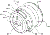
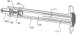
To provide pneumatic force to retract the needle 22, and referring to fig. 2, a propellant release unit 34 is provided in a propellant release chamber 36 of the syringe barrel 26, and a puncturing device, such as a lance 38, is provided to puncture the propellant release unit when a post-injection force is applied by the user. In some embodiments, a lance 38 is provided in the propellant release chamber 36. Propellant release from the propellant release unit 34 to the propellant release chamber 36 applies a force to a needle retraction assembly 108 as described below to retract the needle 22 into a retraction cavity 29 defined in the plunger 28.
In the illustrated embodiment, and with particular reference to fig. 5 and 6, an exemplary embodiment of the propellant release unit 34 has a rigid housing 46 defining a propellant chamber 47 therein. The propellant is held in a propellant chamber 47, the housing of which contains the propellant. In the illustrated embodiment, the propellant is retained by a sealing engagement of the sealing membrane 48 with the upper rim of the rigid housing 46. Examples of propellant release units 34 that may be used in some embodiments of the present invention include gas release units such as described in patent co-pending patent application No. pct/IB2014/060187 entitled gas release unit, filed 3/26/2014, which is incorporated herein by reference in its entirety. In other embodiments, other types of propellant-containing propellant release units or housings may be used, two substances may be contained in the propellant release unit 34 that may be mixed together to generate a gas, and so forth.
In the illustrated embodiment, the propellant release unit 34 has an axially extending central bore 49 such that the overall shape of the propellant release unit 34 is cylindrical with a central extending bore 49, thereby allowing the needle 22 to pass through the propellant release unit 34. In the illustrated embodiment, the inner circumference of the propellant release unit 34 is provided with a plurality of axially extending ridges 51 which project radially inwardly. In some embodiments, ridges 51 help ensure that a channel for propellant flow is readily available so that when the propellant contained in propellant release unit 34 is released, propellant can flow through the channel to reach needle retraction assembly 108 described below. In the illustrated embodiment, the central aperture 49 of the propellant release unit 34 surrounds the elongated central neck 84 of the needle guide 80 (fig. 10), and the ridges 51 help to prevent a seal from being formed between the inner circumference of the propellant release unit 34 and the elongated central neck 84 after the propellant release unit 34 has been pierced. In embodiments having other configurations, the ridge 51 may help prevent a seal from being formed between the propellant release unit 34 and other components of the syringe assembly 20. In some embodiments, the ridge 51 is omitted and the tolerance between the propellant release unit 34 and other components of the syringe assembly 20, such as the elongated central neck 84, is sufficient to ensure that a channel remains available that enables the flow of the released propellant after the propellant release unit 34 is pierced.
Referring to fig. 2, to facilitate retraction of needle 22 when propellant is released from propellant release unit 34, plunger 28 includes a retraction cavity 29 defined therein to accommodate needle 22 after retraction of needle 22, and a lock tip 31 at the distal end of plunger 28 to facilitate retraction of needle 22 by its engagement with needle hub 32 to provide a needle retraction assembly 108 in a manner to be described hereinafter.
With particular reference to fig. 7, in the illustrated embodiment, the needle 22 is releasably retained in its starting position via the needle hub 32, as described below. A needle hub 32 is provided at or near the proximal end of needle 22. In some embodiments, needle 22 may be crimped onto, bonded to, or otherwise securely fixed to needle hub 32. In some embodiments, needle 22 is insert molded with needle hub 32 to make a single piece. Needle hub 32 securely holds needle 22 against an injection force applied distally when medicament is injected into a patient or against a loading force proximally when medicament is withdrawn into medicament chamber 30, but is releasable in the proximal direction in response to a post-injection force applied by a user, as described below.
In the illustrated embodiment, the alignment feature of the needle hub 32 comprises a generally cylindrical locking element at the proximal end of the needle hub that is configured to mate with a locking channel 92 and locking edge 85 (fig. 11A) provided on the locking tip 31 when a user applies a post-injection force to the syringe 20. The generally cylindrical locking element of needle hub 32 has a tapered portion 57 and a generally planar locking edge 58. Tapered portion 57 flares radially outward in a distal direction on the proximal end of needle hub 32 to provide a locking edge 58 of needle hub 32 along the outer distal edge of a portion of needle hub 32. In use, the tapered portion 57 may slide into the locking tip 31 of the plunger 28 to allow the locking edge 58 to slide over and engage the locking channel 92 and locking edge 85 of the plunger locking tip 31, as described below.
Although the locking element is described and illustrated as being generally cylindrical, it is possible that the locking unit may alternatively be provided as one or more discrete protrusions arranged to cooperate with the locking channel 92 in use (i.e. a generally cylindrical locking element may be broken down into one or more discrete pieces rather than being a fully rotatable element). In some embodiments, providing the locking element of needle hub 32 as a generally cylindrical locking element eliminates the need to ensure that needle hub 32 is placed in a particular orientation during manufacture of syringe assembly 20 (i.e., so that the locking element can be used to mate with locking channel 92 regardless of its orientation as it is inserted into auxiliary wall 60).
In some embodiments, the amount of force required to engage the needle hub 32 and lock tip 31 is very small, for example less than 1lb of force. In some embodiments, providing one feature (i.e., locking edges 58 and 85 in the illustrated embodiment) for engaging needle hub 32 and lock tip 31, and another feature (i.e., tapered surfaces 64 and 94, as described below) for providing a seal between needle hub 32 and lock tip 31, allows for better improvement in the force required to sealingly engage needle hub 32 and lock tip 31.
In the illustrated embodiment, referring to fig. 8, the sealing feature of needle hub 32, which sealingly engages lock tip 31, includes tapered surface 64 that engages a corresponding tapered surface 94 on central protrusion 89 of lock tip 31. In the illustrated embodiment, a tapered surface 64 is provided in a proximal portion of the needle hub 32 that is generally cylindrical and has an axially extending opening 65 therethrough to allow fluid flow through the needle 22 into and out of the medicament chamber 30. Tapered surface 64 is tapered inwardly in the distal direction so that tapered surface 64 is tapered inwardly toward the proximal portion of the needle. The proximal portion of opening 65 is thus wider than the distal portion of opening 65 so that tapered surface 94 of lock tip 31 may be received therein.
In the illustrated embodiment, the mating features of the needle hub 32 that mate with the auxiliary wall 60 to secure the needle hub 32 (and thus the needle 22) are an O-ring seal 69 and two conical seals 70. The O-ring seal 69 and the conical seal 70 are generally cylindrical. This sealing feature is provided on the needle hub 32 remote from the locking unit so that the locking unit of the hub 32 can cooperate with the locking tip 31 in use. In the illustrated embodiment, the O-ring seal 69 is provided as a sealing rib integrally formed with the needle hub 32. An O-ring seal 69 provided as a sealing rib sealingly engages the recess 61 of the secondary wall 60 (fig. 9B). Tapered seals 70 of hub 32 cooperate with correspondingly shaped tapered regions 53 of secondary wall 60 to provide additional sealing to prevent the flow of medicament from between needle hub 32 and secondary wall 60. All of the secondary wall 60, the O-ring seal 69 and the conical seal are concentric such that the O-ring seal 69 and the conical seal 70 sealingly engage the recess 61 of the secondary wall 60 around their entire circumference.
In the illustrated embodiment, a secondary wall retention feature 88 in the form of a syringe inner wall (fig. 2) is provided that extends circumferentially around the inner surface of syringe barrel 26 and projects radially outward to facilitate positioning of secondary wall 60 during assembly of syringe assembly 20. The secondary wall retention features 88 are radially outwardly extending protrusions on the inner surface of the syringe barrel 26. Secondary wall retention feature 88 is located at a suitable position in the axial direction of syringe barrel 26 such that secondary wall 60 may be inserted into syringe barrel 26 through its distal opening and contacting secondary wall retention feature 88, secondary wall retention feature 88 being located at or near the end of the user's application of injection force at which secondary wall 60 will contact the distal end of plunger 28. Thus, the secondary wall retention feature defines the axial position of the secondary wall 60 during assembly.
In some embodiments, as shown in fig. 9C, the secondary wall retention feature is provided as one or more discrete protrusions 88A that extend radially outward from the inner surface of the syringe barrel 26, rather than being provided as a full rotational feature. In the illustrated embodiment of fig. 9C, four protrusions 88A are provided that extend radially outward to prevent the secondary wall 60 from being inserted too far into the proximal direction of the syringe barrel 26 during assembly. Although the number of protrusions 88A is shown as 4 and symmetrically disposed along the inner circumference of syringe barrel 26, any number or location of protrusions 88A (e.g., 2, 3, 5,6, 7,8, 9, or more) may be used, so long as the protrusions 88A are sufficient to prevent secondary wall 60 (and its needle hub 32 and needle 22, which are supported and disposed by secondary wall 60) from sliding too far in the proximal direction.
The auxiliary wall 60 has a central aperture 62 (fig. 9A) through which the needle hub 32 is received. Referring to fig. 9A, 9B and 10, in the illustrated embodiment, the secondary wall 60 includes a pair of radially outwardly projecting O-ring features 59 on an outer surface thereof. In some embodiments, O-ring feature 59 helps ensure a good seal between secondary wall 60 and the inner surface of syringe barrel 26. The O-ring feature 59 may also help ensure reproducible movement of the secondary wall 60 within the syringe barrel 26 when a user applies a post-injection force as described below, for example by ensuring continuous sliding of the secondary wall 60 in the axial direction and maintaining proper axial alignment of the secondary wall 60 within the syringe barrel 26.
The auxiliary wall 60 further comprises a recess 73 for accommodating a locking unit of the needle hub 32, i.e. the tapered portion 57 and the locking edge 58 in the shown embodiment. In the illustrated embodiment, the proximal portion of needle hub 32 is flush with the proximal portion of auxiliary wall 60. In some embodiments, such a configuration helps minimize dead volume in syringe assembly 20; however, other configurations may be used (e.g., the proximal end of the needle hub 32 may protrude slightly beyond the secondary wall 60 in the proximal direction, or may be recessed in the recess 73 of the secondary wall 60, so long as the plunger tip 31 is easily engaged with the needle hub 32).
In the illustrated embodiment, the secondary wall 60 is symmetrical about a central radial axis. Thus, the auxiliary wall 60 is provided with two recesses 73, even if only one recess accommodates the locking unit of the needle hub 32. In some embodiments, providing secondary wall 60 that is symmetric about a central radial axis avoids the need to ensure that secondary wall 60 is inserted in a particular orientation during manufacture of syringe assembly 20.
The central opening 62 of the secondary wall 60 also includes a central receptacle 61 that sealingly mates with mating features of the needle hub 32, i.e., an O-ring 69 and a conical seal 70 in the illustrated embodiment. Movement of the needle hub 32 in the axial direction as a result of the presence of the central socket 61, which results in the formation of a radial channel on the inner surface of the subsidiary wall 60, is limited by a pair of radially inwardly extending projections 67 on the inner surface of the subsidiary wall 60. The conical seal 53 of the secondary wall 60 is provided on the surface of the projection 67 which is in contact with the corresponding conical seal 70 of the needle hub 32.
The fit of needle hub 32 in secondary wall 60 is strong enough to prevent needle hub 32 from moving during application of an injection or loading force by a user, but weak enough such that movement of secondary wall 60 via application of a post-injection force by plunger 28 pushes secondary wall 60 to slide distally over needle hub 32, thus releasing needle hub 32 (and thus needle 22) for retraction.
Any suitable material may be used to make secondary wall 60 as long as it allows secondary wall 60 to initially retain needle hub 32 and then release needle hub 32 upon application of a post-injection force. In some embodiments, secondary wall 60 is made of an elastomer having a suitable durometer to release needle hub 32 upon application of a post-injection force.
In the illustrated embodiment, the central opening 62 of the secondary wall 60 is provided with surface features that prevent an airtight seal from being formed between the secondary wall 60 and the needle hub 32 after the needle hub 32 is displaced from its starting position due to the release of propellant from the propellant release unit 34. This ensures that there is a passage available for propellant flow from the propellant release unit 34 (after it has been punctured) to the needle retraction assembly 108 described below. In the illustrated embodiment, the surface feature that prevents the formation of the hermetic seal is the channel 71. The channel 71 extends axially along the projection 67 of the secondary wall 60 to provide a path for propellant flow between the needle hub 32 and the secondary wall 60 after the needle hub 32 has been disengaged from the secondary wall 60 by application of a post-injection force (the seal provided by the O-ring seal and the conical seal 70 has thus been removed) to ensure propellant flow and to apply upstream biasing pressure to the needle retraction assembly 108.
Referring to fig. 10 and 11A-11C, the locking tip 31 is described in more detail. In the illustrated embodiment, to facilitate manufacture and reduce cost, the lock tip 31 is a single-piece overmolded piece having two parts: a rigid member 90 for snap-fit engagement with the locking edge 58 of the needle hub 32 and with a catch projection 97 of the plunger 28 (as described below); and a more flexible over-molded part 91 that sealingly engages the inner surface of the retraction cavity 29 to prevent the medicament from flowing past the lock tip 31 and to ensure a good seal so that pressure can be generated by the release of propellant to move the retraction assembly 108 in the proximal direction. Typically, rigid component 90 may be made of a rigid material, such as polycarbonate (polycarbonate), or StyroluxTMOr a hard plastic such as polypropylene (polypropylene). The more flexible member 91 may typically be made of a relatively more flexible material such as silicone, thermoplastic elastomer, or other similar polymers.
The rigid component 90 of the locking tip 31 has a generally cylindrical shape so that it can fit into the plunger cavity 29 and includes at least one locking aperture 92 formed along at least one edge thereof. The locking aperture 92 includes a locking edge 85 at its distal edge for snap-fit engagement with the locking edge 58. When a user applies a post-injection force, the locking aperture 92 snap-fits (via locking edge 85) with the locking edge 58 of the needle hub 32 such that the locking tip 31, needle hub 32 and needle 22 come together to provide an assembly 108 for retraction (referred to herein as a retraction assembly). Although in the illustrated embodiment, the locking aperture 92 is shown extending through a portion of the rigid component 90, any suitable configuration may be used so long as it allows a snap fit with the locking edge 58 of the needle hub 32. For example, two, three, or more locking apertures may be provided to mate with the locking edge 58. Additionally, while locking channel 92 is shown as a slot or hole formed through rigid component 90, locking channel 92 may alternatively be formed as a channel on the inside surface of rigid component 90 without extending completely therethrough.
In an exemplary embodiment, a single locking aperture 92 is provided in lock nib 31 to minimize the amount of force required to sealingly engage lock nib 31 and needle hub 32. The presence of the additional locking hole 92 increases the amount of force required to snap locking edge 58 and locking hole 92 together to seal lock tip 31 and needle hub 32, and this increased force must be balanced with the other forces required to release needle hub 32 and lock tip 31 to retract when the user applies the post-injection force, as outlined in more detail below. Fig. 11B shows an exemplary embodiment of the locking tip 31A with only one locking aperture 92 and more clearly shows the distal recess 95 that mates with the catch projection 97 of the tip of the plunger 28. Fig. 11C shows an exemplary embodiment of the locking tip 31 as shown in fig. 11A, having two locking apertures 92.
The flexible member 91 of the locking tip 31 has a pair of sealing rings 93 provided by radially outwardly extending protrusions on the outer circumference of the substantially cylindrical flexible member 91. Different numbers of sealing rings may be used. In some embodiments, the use of two sealing rings rather than only one sealing ring may help ensure linear travel of the needle assembly 108 during retraction. The sealing ring 93 sealingly engages the inner surface of the retraction cavity 29. The sealing engagement between the sealing ring 93 and the retraction cavity 29 is sufficiently secure and coacts with the engagement between the catch projection 97 and the distal recess 95 such that the lock nib 31 does not move in response to an applied loading or injection force, but such that the sealing ring 93 allows the lock nib 31 (and thus the retraction assembly 108) to slidably move into the retraction cavity 29 when the catch projection 97 has disengaged from the distal recess 95 in response to pressure applied by a propellant released after puncturing the propellant release unit 34.
The flexible component 91 of the locking tip 31 also includes a central cylindrical protrusion 89 having a tapered surface 94 that is complementary to the tapered surface 57 of the needle hub 32 (i.e., the tapered surface 94 is inwardly tapered from its proximal end to its distal end) such that when a user applies a post-injection force, the mating of the tapered surfaces 94 and 57 can provide a seal to prevent any further fluid flow through the needle 22. A central cylindrical protrusion 89 is disposed in and at a distal portion of the flexible member 91 and is axially aligned with the rigid member 90 of the locking tip 31 so that it can mate with the needle hub 32.
In some embodiments, including the embodiments shown, to facilitate retaining lock tip 31 at the distal end of plunger 28 during application of a loading or injection force, lock tip 31 includes one or more distal recesses 95 formed in rigid assembly 90. Distal recess 95 extends radially inward around a distal portion of the outer surface of lock tip 31 and is engageable with one or more radially inward extending catch protrusions 97 (fig. 12) formed on the inner surface of the distal end of plunger 28. In the illustrated embodiment, two catch projections 97 are provided, spaced 180 apart. However, other numbers of catch projections 97 and other configurations may be used (e.g., four catch projections 97 spaced 90 apart, three catch projections 97 spaced 120 apart, or even an asymmetrical plurality of catch projections 97, although smoother retraction of the needle assembly 108 may be obtained by symmetrically spaced apart holding catch projections 97).
In alternative embodiments, catch projection 97 and/or distal recess 95 may be omitted, and a different fit between plunger lock tip 31 and the distal end of plunger 28 may be used, e.g., a sufficiently tight but releasable press-fit or friction fit, a connection by a frangible connector or frangible piece of material that prevents release of plunger lock tip 31 during application of loading or injection forces, but allows release of plunger lock tip 31 in response to post-injection forces, etc.
The engagement between the distal recess 95 and the catch projection 97 is broken by the post-injection force applied by the user. The force required to disengage distal recess 95 and catch projection 97 should be greater than the force required to sealingly engage lock tip 31 and needle hub 32. If the force required to disengage the distal recess 95 and catch projection 97 is close to or less than the force required to sealingly engage the lock nib 31 and needle hub 32, there is a risk that when the user applies the post-injection force, the lock nib 31 will disengage from the distal recess 95 and move proximally into the retraction cavity 29 without engaging the needle hub 32. This will result in the needle 22 not being retracted. In one exemplary embodiment of a syringe having a volume of 3mL, and an overall actuation force of about 7lbs (i.e., the minimum post-injection force that must be applied by the user to cause retraction of needle 22) to retract needle 22, the force required to sealingly engage lock tip 31 and needle hub 32 is less than 1lb, and in some embodiments is in the range of about 0.7lbs, while the force required to disengage distal recess 95 and catch projection 97 is greater than 2lbs, and in some embodiments is in the range of 2.5 lbs.
In the illustrated embodiment, the catch projection 97 is formed on a region of the plunger 28 located between two axially extending channels 100 in the distal end of the plunger 28. In some embodiments, disposing the catch projection 97 between the channels 100 provides a degree of flexibility to the area of the plunger 28 carrying the catch projection 97, which facilitates molding of the catch projection 97 in the manufacture of the plunger 28. In some examples, channel 100 is omitted.
In the illustrated implementation, the plunger seal 98 is manufactured as an over-molded to the plunger 28. In these embodiments, the plunger seal 98 is an elastomeric overmold and the channel 100 is filled with the elastomeric overmold. In other embodiments, the plunger seal 98 is manufactured as a separate component from the plunger 28, and the two components may be joined together in any suitable manner, such as by a sufficiently tight friction fit, using a suitable adhesive, and so forth. The plunger seal 98 is in sealing but slidable engagement with the inner surface 44 of the syringe 24 to facilitate injection of the medicament in a manner similar to conventional syringes.
The needle 22 is hollow and has a downstream tip 52 (fig. 1 and 2) for injecting medicament into an injection subject and an upstream access opening 54 (fig. 8) for receiving medicament from the medicament compartment 30. In some embodiments, a needle seal 56 (fig. 2) is provided to seal the distal end of the syringe 24. In some embodiments, the needle seal 56 seals the propellant release chamber 36 more tightly by sealing engagement with the needle 22 to enhance the seal between the outer diameter of the needle 22 and the needle guide 80 and prevent escape of the released propellant along the outer diameter of the needle 22 when the propellant is released in the propellant release chamber 36. In some embodiments, the needle seal 56 is secured to the needle guide 80 in any suitable manner, such as by a suitable adhesive, by a compression fit between the needle guide 80 and the syringe barrel 26 or between portions of the needle guide 80, over-molding, or the like. In some embodiments, the needle seal 56 may be integrated with the over-molded piece of the needle guide 80. In some embodiments, the needle seal 56 may help retain the needle 22 in the syringe 24 by providing a recurring barrier for the needle once the needle 22 is retracted. In some embodiments, the needle seal 56 may help prevent any medicament from dripping out of the end of the needle 22 and into the surrounding environment after use.
The needle seal 56 may be made of a soft, flexible material, such as polyisoprene (polyisoprene). In some embodiments, the needle seal 56 may be made of silicon or rubber. In some embodiments, the needle seal 56 may be made of soft surgical grade rubber or silicon or the like, and when the needle 22 is retracted, the needle seal 56 closes and self-seals the aperture left by the needle 22. In embodiments where the needle seal 56 is made of polyisoprene, the needle 22 may be used to puncture the needle seal 56 during assembly of the syringe assembly 20, which may avoid the need to cut the needle seal 56 with a blade prior to assembly.
A propellant release unit 34 is contained within the syringe barrel 26 at the distal end of the needle hub 32, the propellant release unit 34 having a propellant release chamber 36 therein. In the illustrated embodiment, propellant release chamber 36 is defined between the distal end of syringe barrel 26, needle guide 80 and needle hub 32. Depending on the configuration of the components of syringe assembly 20, propellant release chamber 36 may be defined between other components of syringe assembly 20, depending on the particular configuration of components used. The propellant release chamber 36 confines the propellant released by the propellant release unit 34 such that the propellant exerts a force on the lock tip 31 and the needle hub 32 to retract the needle 22 in the proximal direction. The propellant release unit 34 is oriented in the propellant release chamber 36 such that the sealing membrane 48 faces the lance 38. In the illustrated embodiment, an elongated central neck 84 (described below) of the needle guide 80 has a substantially cylindrical shape and is received in the central bore 49 of the propellant release unit 34.
In some embodiments, the plunger 28 and syringe barrel 26 include plunger locking features to maintain the position of the plunger 28 at or near the distal limit of plunger 28 travel. In some embodiments, a locking feature secures plunger 28 within syringe barrel 26 during needle retraction. In some embodiments, the locking feature prevents tampering with or reuse of syringe assembly 20 after syringe assembly 20 has been used and needle 22 has been retracted.
In the illustrated embodiment, referring to fig. 13 and 14, the plunger locking feature is provided as snap fit engagement members 66, 68 disposed at the proximal ends of the syringe barrel 26 and plunger 28. In the illustrated embodiment, a syringe snap-fit engagement member 66 provided at the proximal end of the syringe barrel 26 projects proximally from the proximal end of the syringe barrel 26 and has a radially inwardly extending locking projection 77 at its proximal end. The locking projection 77 has an inwardly angled slidable surface 78, a corresponding inwardly angled slidable surface 81 of the plunger 28 slidable past the slidable surface 78 (the inwardly angled slidable surface 78 is inwardly angled and distal to the outer edge of the locking projection 77), and a radially extending locking surface 79 distal to the slidable surface 78. The locking surface 79 is configured to lock with a corresponding locking surface 82 of the plunger 28. In the illustrated embodiment, the locking surface 79 is generally straight extending in a radial direction, and the locking surface 79 is likewise generally straight extending in a radial direction such that once the locking surface 80 slides over the angled slidable surface 78 and engages the locking surface 79, the plunger 28 cannot subsequently be withdrawn from the syringe barrel 26. In alternative embodiments, other configurations that prevent the plunger 28 from sliding out of the syringe barrel after the plunger locking feature is engaged may be used.
The plunger snap-fit engagement member 68 has an outwardly angled slidable surface 81 that can slide over the inwardly angled slidable surface 78, and a generally radially extending locking surface 82 that can slide over and mate with the locking surface 79. The angled slidable surface 81 has a shape that is complementary to the angled slidable surface 78 (angled outward in the illustrated embodiment and in a proximal direction relative to the proximal end of the plunger 28), and in other embodiments, has alternative shapes for the surfaces 78, 81 that can slide past each other, such as slightly curved surfaces. In use, at or just prior to the end of the post-injection force application, the user may cause the angled slidable surfaces 78, 81 to move past each other, thereby allowing the locking surfaces 79, 82 to contact in a snap fit, thus locking the plunger 28 and syringe 24.
In the illustrated embodiment, two pairs of snap- fit engagement members 66, 68 are provided, one on each opposing side of the syringe assembly 20. Any desired number and location of snap fit engagement members 66, 68 (e.g., three, four, or more pairs of snap fit engagement members 66, 68) may be used, so long as these can be used to lock the plunger and syringe 24.
In the illustrated embodiment, an additional mechanism is provided to prevent tampering with or reuse of syringe assembly 20 after use. A generally circular anti-tamper ring 86 is provided that is shaped and configured to receive a correspondingly shaped proximal end of plunger 28 therein. An anti-tamper ring 86 projects axially in a proximal direction from the proximal end of syringe 24 to generally encircle the distal end of plunger 28. Thus, when the snap- fit engagement members 66, 68 are snap-fit, the generally circular ring 86 surrounds the proximal end of the plunger 28. Thus, if a user wishes to attempt to pry open or tamper with plunger 28 and syringe 24 (e.g., to attempt to remanufacture and reuse syringe assembly 20), the generally circular ring 86 will provide a barrier to prevent the user from pushing a tool under the tip of plunger 28 in an attempt to pry open plunger 28 and syringe 24. Although a generally circular shape is described and shown, other corresponding shapes may be used for the end of the plunger 28 and the generally circular ring 86 (e.g., oval or other desired shape) so long as the generally circular ring 86 encircles the distal end of the plunger 28 and prevents the user from inserting a tool to pull the plunger 28 out of the syringe 24. In some embodiments, the generally circular ring 86 is omitted.
In some embodiments, the plunger 28 includes one or more channels, such as a vent 74 formed therein. In some embodiments, vent 74 allows air to be released from retraction cavity 29 upstream of needle hub 32 and lock tip 31 when needle 22 is retracted. In some embodiments, the vent 74 is disposed proximate or near the upstream limit of travel of the retraction assembly 108 when fully retracted to avoid leakage of propellant pressure (and ultimately an upstream biasing force), which may stop the upstream travel of the needle 22 before the needle 22 is fully retracted, which may occur, for example, if the vent 74 is disposed too far from the upstream limit of travel of the needle assembly 108. In the illustrated embodiment, a vent 74 is provided through the distal end of the plunger 28 to place the region of the retraction cavity 29 upstream of the lock tip 31 in fluid communication with the outside air. In some embodiments, where a redundant propellant venting mechanism is provided, such as hole 110 (described below), vent hole 74 is omitted and all venting is accomplished through hole 100.
In some embodiments, plunger 28 includes a plunger tip flange 76 to provide a support surface for a user's fingers, for example, to facilitate pulling plunger 28 in a proximal direction of syringe barrel 26 to draw liquid into medicament compartment 30 and/or administer a medicament using syringe assembly 20.
In some embodiments, the plunger 28 includes a plurality of thumb ridges 72 on a distal portion of the plunger 28 and/or a plunger tip flange 76. In some embodiments, thumb ridge 72 prevents the user's fingers from blocking vent 74.
In some embodiments, the plunger 28 includes an excess propellant discharge mechanism to discharge any remaining residual propellant after retraction of the needle 22 is fully completed. Referring to fig. 15, in some embodiments, a propellant bore 110 is provided through the plunger 28. Propellant vent 110 is provided a sufficient distance proximally of lock tip 31 so that the full combined length of retraction assembly 108 can be accommodated into syringe barrel 26 distally of propellant vent 110 so that no portion of needle 22 protrudes out of syringe 26 after retraction. In use, the retraction assembly 108 moves proximally within the retraction cavity 29 in response to the force exerted by the released propellant. Air located upstream of the lock tip 31 is forced out of the vent holes 74 and/or 100. After the needle 22 is fully retracted, the lock tip 31 may move proximally past the propellant vent 110. Once lock tip 31 moves proximally past propellant vent 110, the passage in the space between plunger 28 and syringe 24 is opened so that any excess propellant can exit syringe assembly 20. That is, the propellant release chamber 36 is in fluid communication with the outside air once the lock tip 31 moves proximally past the propellant vent 110. In some embodiments, the provision of propellant vent 110 as described above avoids retaining any excess pressure released by propellant release unit 34 in syringe assembly 20 after needle 22 is retracted. In some embodiments, two, three, four or more propellant vents 110 may be provided and spaced around the circumference of the plunger 28, but should be positioned at a similar distance from the proximal end of the locking tip 31 to allow the retraction assembly 108 to be retracted to a desired position within the retraction cavity 29.
In an alternative embodiment, as shown in figures 21 and 22, the propellant vent 110 may be eliminated and the venting of any remaining propellant may be achieved by a series of grooves or keyways provided on the inner surface of the retraction cavity 29. The grooves or keyways 111 are axially disposed in the retraction cavity 29 such that they begin to be located distally substantially where the propellant vent 110 is disposed (i.e., a sufficient distance of the proximal end of the lock tip 31 to allow the retraction assembly 108 to be retracted to a desired position in the retraction cavity 29). The proximal end of the groove or keyway 111 extends along the inner surface of the retraction cavity 29 to a very proximal portion of the retraction cavity 29 to allow propellant to be expelled from the retraction cavity 29. In some such embodiments, a suitably disposed vent hole 74 or other suitable venting mechanism is provided in plunger tip flange 76 so that propellant can still be expelled from the proximal end of retraction cavity 29 even when plunger 28 has reached the far most limit of its travel in syringe 24. In some embodiments, both the propellant vent 110 and the groove or keyway 111 may be present as long as a path for fluid communication of propellant flow is provided between a suitable axial location in the retraction cavity 29 (e.g., distal to the upstream limit of retraction of the lock tip 31 when the needle 22 is retracted) and the ambient air.
In some embodiments, the propellant release unit 34 is initially secured to the propellant release chamber 36 in any suitable manner to minimize the risk that the sealing membrane 48 may be prematurely punctured by the lance 38. For example, the outer surface of the housing 46 of the propellant release unit 34 may be friction fit with the inner surface 44 of the syringe barrel 26, or with an elongated central neck 84 of the needle guide 80 (described below), or the propellant release unit 34 may begin to adhere to the collar 60, or central neck 84, in any suitable manner, such as by adhesive or the like. In some embodiments, including embodiments in which movement of the propellant release unit 34 is required to puncture the propellant release unit 34 when a post-injection force is applied, the adhesive used should be weak enough to allow the propellant release unit 34 to move when a post-injection force is applied, but strong enough to hold the propellant release unit 34 during application of a loading or injection force.
In some embodiments, the propellant release unit 34 is not in any way particularly secured to the propellant release chamber 36 (i.e., the propellant release unit 34 is free floating), but the material from which the sealing membrane 48 is made is sufficiently strong that contact with the lance 38 alone (e.g., as may occur during shipping or loading of the syringe assembly 20) is insufficient to puncture the propellant release unit 34 without the application of post-injection force by the user.
The pressure and volume of propellant in the propellant release unit 34 should be sufficient to ensure that the needle 22 can be fully retracted into the retraction cavity 29 when the propellant release unit 34 is pierced. A propellant release unit for use with a larger volume syringe may have a larger volume (and therefore contain more propellant) than a propellant release unit for use with a smaller volume syringe. The appropriate pressure volume of propellant contained in propellant release unit 34 may be determined by one skilled in the art depending on the propellant to be used and the desired temperature range for use of syringe assembly 20.
A mechanism for puncturing a sealing membrane 48 of the propellant release unit 34 in response to a post-injection force is provided in the propellant release chamber 36. In the illustrated embodiment, a propellant release trigger in the form of one or more lances 38 is provided. The lance 38 is secured in the syringe barrel 26 in any suitable manner. In the illustrated embodiment, the lance 38 is formed as part of a needle guide 80 that is secured to a distal portion of the syringe barrel 26. In an alternative embodiment, the lance 38 is secured directly to the distal end of the syringe barrel 26.
The lance 38 may alternatively be mounted to the secondary wall 60 in a suitable location, or the distal end of the plunger 28 (with a corresponding aperture provided through the secondary wall 60 to allow the lance to pass therethrough), or integrally formed with these components, such that the lance 38 is arranged and configured for use in puncturing the propellant release unit 34 in response to an applied post-injection force. In these embodiments, the orientation of the propellant release unit 34 will be flipped 180 ° so that the sealing membrane 48 faces the lance 38 to facilitate puncturing upon application of the post-injection force. In an alternative embodiment, the propellant release unit 34 is made entirely of a rupturable material (i.e., does not include any rigid walls such as the housing 46) and thus the orientation of the propellant release unit 34 does not have an effect so long as the propellant release unit is disposed such that it contacts the piercing mechanism upon application of the post-injection force.
In the illustrated embodiment, referring to fig. 16, three lances 38 are provided to pierce the propellant release unit 34 in response to a post-injection force applied by a user. Any desired number of lances may be used, such as two, four, five, six or more. The lance 38 need not be symmetrically configured, but providing a symmetrically oriented lance 38 may help ensure reliable piercing of the propellant release unit 34.
Each lance 38 has a generally conical shape and is oriented such that its sharp end projects toward the propellant release unit 34 (i.e., toward the proximal end of the illustrated embodiment). In the illustrated embodiment, each lance 38 is provided with a side recess 39. The side notches 39 help to ensure that the propellant flow path created during puncturing of the propellant release unit 34 is not obstructed by the sealing membrane 48 of the propellant release unit 34. In some embodiments, the side notches 39 are omitted.
In the illustrated embodiment, the lance 38 is manufactured as part of the needle guide 80. The lance 38 projects towards the propellant release unit 34, i.e. in the same direction proximally as the elongate central neck 84 of the needle guide 80 in the illustrated embodiment. The needle guide 80 is secured to the distal end of the syringe 24 in any suitable manner, such as by friction fit, suitable adhesive, bonding, spin welding, or the like. In one exemplary embodiment, the needle guide 80 is ultrasonically welded to the distal end of the syringe body 26.
In some embodiments, to prevent the plunger 28 from being completely withdrawn from the syringe 24 by the user, a plunger retention feature is provided. In the illustrated embodiment, referring to fig. 17, in some embodiments an internal protrusion 112 is provided at the distal end of the syringe 24 and a corresponding external protrusion 114 is provided at the distal end of the plunger 28. The projections 112, 114 are shaped and arranged so that the plunger 28 can be inserted into the syringe 24 but cannot be subsequently removed from the syringe 24, or at least cannot be removed without considerable difficulty. In other words, the protrusions 112 and 113 allow for one-way movement of the plunger 28, i.e., the plunger 28 can enter the syringe 24 but cannot exit the syringe 24.
In use, the needle cover 50 may be removed in any suitable manner to expose the needle 22. If necessary, a downstream force is applied by the user to the upstream plunger tip flange 76 to expel air from the medicament compartment 30. When substantially all of the air is expelled from the medicament compartment 30, but before the snap- fit engagement members 66, 68 are mated, the tip 52 of the needle 22 may be submerged in the liquid medicament contained in the supply vial, which may be of a conventional type.
The medicament or other liquid for injection is drawn into the medicament chamber 30 by applying a loading force by withdrawing the plunger 28 distally relative to the syringe barrel 26 in the same manner as in a typical syringe. After the medicament compartment 30 is filled with the desired volume of medicament, air may be removed in the usual manner by inverting the syringe assembly 20 so that the needle 22 is facing upwards, tapping the syringe 24 to remove any air therein and allow the air to float on the medicament, and applying a distally directed force to push the plunger 28 so that residual air is expelled through the needle 22.
The needle 22 is arranged at the injection site of the injection subject in the usual manner. The medicament may be released from the medicament chamber 30 by a distally directed force (injection force) applied to the plunger tip flange 76 in the usual manner, thereby causing the plunger seal 98 to exert a distally biased pressure on the medicament contained in the chamber 30. The distally directed biasing pressure is sufficient to urge the medicament through the needle 22. However, this pressure is insufficient to overcome the friction securing the secondary wall 60 to the inner surface of the syringe barrel 26, or securing the needle hub 32 in the secondary wall 60, nor is the corresponding upstream pressure on the end of the plunger 28 sufficient to overcome the friction between the lock tip 31 and the plunger 28.
Referring to fig. 18, one exemplary embodiment of the injector assembly 20 is shown at the end of an injection stroke after all or substantially all or a dose of medicament has been injected into an injection subject. Once the user is ready to actuate the retraction mechanism, the user continues to apply force to the plunger 28 in the distal direction, now the post-injection force.
Since the application of the post-injection force must result in mechanical movement of the components of the syringe assembly 20 as described below, the force applied as the post-injection force must be greater than the force applied as the injection force. The injection force required to perform any given injection may vary, for example, due to abnormally high flow resistance in the tissue of a particular patient. In a typical scenario, for the illustrative 3mL syringe, it is expected that the injection force will be on the order of less than about 1.5lbs, while the post-injection force will be on the order of about 5-7 lbs.
Referring to fig. 19, continued movement of plunger 28 in response to an applied post-injection force moves the distal end of plunger 28 and plunger seal 98 distally past secondary wall retention feature 88 (or 88a in some embodiments in the illustrated embodiment, secondary wall retention feature 88 has a proximal angled portion 87 (fig. 2 and 9D). proximal angled portion 87 is angled radially outward in the proximal direction between secondary wall retention feature 88 and inner surface 44 of syringe barrel 26. in some embodiments, when a user applies a post-injection force, proximal angled portion 87 facilitates plunger seal 98 sliding past secondary wall retention feature 88, which may help reduce the amount of force that a user must apply to retract needle 22.
As the distal end of plunger 28 moves past secondary wall retention feature 88, plunger 28 exerts a distal force on secondary wall 60, causing secondary wall 60 to move in a distal direction. When the auxiliary wall 60 is moved in the distal direction, the needle hub 32 separates from the auxiliary wall 60 because the needle hub 32 is prevented from moving in the distal direction by the elongated central neck 84 of the needle guide 80. This causes the seals 69 and 70 to release and the auxiliary wall 60 to move distally relative to the needle hub 32.
Continued movement of the secondary wall 60 in the distal direction also causes the locking tip 31 of the plunger 28 to slide over the tapered portion 57 of the needle hub 32 such that the locking edge 58 of the needle hub 32 mates with the locking channel 92 of the locking tip 31. Needle hub 32 (along with needle 22) thus becomes engaged with lock tip 31 to provide retraction assembly 108. And at the same time, tapered surface 94 of central protrusion 89 of lock tip 31 is in sealing contact with tapered surface 64 of needle hub 32 to prevent further fluid flow through needle 22. After the lock tip 31 is engaged with the needle hub 32, the catch projection 97 is released from the distal recess 95 by continued application of post-injection force, thereby causing the plunger tip 31 to separate from the tip of the plunger 28, which continues to move the plunger 28 in the distal direction, while the central neck 84 of the needle guide 80 prevents the retraction assembly 108 including the lock tip 31 from moving distally.
Further movement of the secondary wall 60 in the distal direction causes movement of the propellant release unit 34 in the distal direction which causes the rupturable membrane 48 of the propellant release unit 34 to contact the lance 38 and be punctured. This releases propellant from the propellant chamber 47 of the propellant release unit 34 in the propellant release chamber 36.
The released propellant remains under pressure in the confines of propellant release chamber 36 and thus applies a proximal force to needle retraction assembly 108.
Referring to fig. 18, an exemplary embodiment is shown in which the propellant release chamber 36 is shown in greater detail. In the illustrated embodiment, propellant release chamber 36 is defined between the distal end of syringe barrel 26, needle guide 50, secondary wall 60, and needle hub 32. When the propellant release unit 34 is punctured, the propellant contained therein is released into the propellant release chamber 36. The released propellant is sealed in the propellant release chamber 36 by the engagement of the needle guide 80 and needle guide seal 56 with the syringe barrel 26 and needle 22, and by the sealing engagement of the O-ring feature 59 of the secondary wall 60 with the inside face 44 of the syringe barrel 26. The compressed propellant is thus constrained to move in the barrel of the syringe 26 in a proximal direction towards the distal bearing surface 102 (fig. 20) of the retraction member 108, which in the illustrated embodiment is provided by the plunger tip 31. Escape of compressed propellant through retraction member 108 is prevented by engagement of sealing ring 93 of lock nib 31 with the inner wall of retraction cavity 29 and by engagement of tapered surfaces 94, 64 on lock nib 31 and needle hub 32 respectively. The released propellant thus exerts a force on the support surface 102 in the proximal direction, thereby causing the retraction assembly 108 to move in the proximal direction.
Biasing pressure in the distal direction causes the needle retraction assembly 108 to slide proximally into the retraction cavity 29, thereby retracting the needle 22 into the retraction cavity 29 (fig. 20 and 15). The volume and pressure of the propellant in the propellant release unit 34 should be sufficient to retract the entire length of the needle 22 into the syringe barrel 26 so that the downstream tip 52 of the needle 22 does not protrude outside of the syringe 24 and thus pose a biochemical hazard. After the lock nib 31 has traveled its continuous path of travel in the proximal direction through the propellant vent 110, any excess propellant pressure is vented. After the lock tip 31 passes the propellant vent 110, the propellant will not apply a distal biasing pressure to the retraction assembly 108 and the retraction assembly 108 will stop in the retraction cavity 29 as shown in fig. 20.
One skilled in the art can select suitable materials to manufacture syringe assembly 20. For example, syringe barrel 26 and plunger 28 may be made from any suitable plastic or thermoplastic, such as polycarbonate (polycarbonate), acrylic (acrylic), copolyester (copolyester), SBC (e.g., Styrolux)TM) And so on. The plunger seal 98 may be made of any suitable material, such as silicone, thermoplastic elastomer, and the like. In some embodiments, the plunger seal 98 may be a self-lubricating seal. In some embodiments, syringe barrel 26 and/or plunger seal 98 may be treated with a medical grade lubricant. Needle 22 may be manufactured from a medical grade needle cannula. The compressed propellant used in the propellant release unit 34 may be any suitable propellant, such as a pharmaceutical grade hydrofluorocarbon (hydro fluorocarbon), such as heptafluoropropane (heptafluoropropane), 1,1,1,2-tetrafluoroethane (1,1,1,2-tetrafluoroethane) or medical grade nitrogen. In some embodiments, heptafluoropropane is a propellant and is selected based on its expansion properties and non-toxicity. Suitable materials for making propellant releasing unit 34 include suitable polymers such as nylon, polyethylene, polypropylene, polystyrene, and the like, or suitable copolymers thereof. Prior to packaging, the assembly may be sterilized in any suitable manner, such as using electron beam radiation, gamma radiation, or ethylene oxide (EtO) gas. These materials selected for manufacturing syringe assembly 20 should be compatible with the medicament to be applied to the subject being injected.
In some embodiments, the syringe 24 is a prefilled syringe, i.e., the syringe 24 has been filled with a predetermined mass of a particular medicament. In use, the prefilled syringe 24 need not be loaded with medicament, but can be readily used to inject the medicament already contained therein into an injection subject in the manner described above, and then to retract the needle 22.
In some embodiments, portions of syringe barrel 26 through which components of the retraction mechanism (e.g., secondary wall 60, needle hub 32) may be visible may be frosted (i.e., made translucent) to minimize visual impact of the presence of the retraction assembly as compared to conventional syringes.
In some embodiments, as shown in fig. 23, the propellant in the gas release unit, e.g., gas release unit 34, is not provided and the propellant is contained in a single propellant release unit that is integrally formed as part of a pneumatically actuated retractable syringe.
Referring to fig. 23, an exemplary embodiment of a retractable needle syringe assembly 220 having a single propellant release unit 320 is shown. Elements of retractable needle syringe assembly 220 that are equivalent to elements of retractable needle syringe assembly 20 described above are depicted with reference numerals incremented by 200 and are not described repeatedly herein. In the illustrated embodiment, the single propellant release unit 320 is formed as a generally cylindrical channel 322 defined in a needle guide 324 of the retractable needle syringe assembly 220. The cylindrical channel 322 is defined by an inner cylindrical wall 326, an outer cylindrical wall 328, and a bottom 330 disposed in the needle guide 324.
The propellant is sealed in the single propellant unit 320 by a seal 332, which seal 332 extends over the cylindrical channel 322 at its proximal end. In the illustrated embodiment, the seal 332 sealingly engages upper proximal edges (shown as 334A/334B and 336A and 336B in fig. 24A and 24B, and collectively referred to as upper proximal edges 334 and 336) of the inner wall 326 and the outer wall 328, respectively. The seal 332 may be secured to the upper proximal edges 335, 336 in any suitable manner, such as by heat sealing, ultrasonic welding, use of a suitable adhesive, and the like.
The seal 332 is arranged and configured such that it can be punctured by the puncturing member 338 when a user applies a post-injection force. In the embodiment shown in fig. 23, the relative directions of single propellant release unit 320 and piercing member 338 are reversed relative to the directions of gas release unit 34 and piercing mechanism 38 described above. Additionally, the central neck of the needle guide 324 (provided by the inner cylindrical wall 326) is relatively shorter than the central neck 84 of the needle guide 80 and the distal portion of the needle hub 232 is correspondingly elongated to facilitate placement of the single propellant release unit 320 in the needle guide 324. The needle guide 324 does not have an elongated center neck equivalent to the center neck 84 of the needle guide 80 so that the seal 332 can be applied directly to the inner and outer cylindrical walls 326, 328 during manufacture to seal the propellant in the channel 322.
The piercing member 338 is disposed at a proximal end of the single beneficial agent release unit 320 (rather than a distal end, as is the case with the disposition of the piercing mechanism 38 with respect to the gas release unit 34). The piercing member 338 projects in a proximal direction and is configured to pierce the seal 332 when a user applies a post-injection force. In some exemplary embodiments, including the illustrated embodiment, the distally projecting piercing member 338 is integrally formed with the disc-shaped bottom 340 as a rigid substrate, while the secondary wall 260 is formed as a resilient overmold of the rigid substrate. In some embodiments, such as shown in fig. 24A and 24B, the tray-shaped bottom 340 is provided with a proximally projecting extension 342 that helps form the plastic-encased secondary wall 260 as a tray-shaped bottom 340. In some embodiments, a hole (not shown) is provided through the proximally projecting cylindrical extension 342. The cylindrical extension 342, including any holes therethrough, helps provide a mechanical interference to lock the plastic coated secondary wall 260 to the disk-shaped bottom 340. In an alternative embodiment, the proximally projecting cylindrical extension 342 may be provided as one or more discrete protrusions, rather than a full rotational cylindrical feature. In another alternative embodiment, the tray-shaped bottom 340 and the secondary wall 260 are formed as separate pieces and joined together in any suitable manner (e.g., a suitable adhesive).
In alternative embodiments, the piercing member 338 and the secondary wall 260 may be manufactured using any suitable method, excluding the disc-shaped bottom 340, and these components may be joined together in any suitable manner, such as, for example, using an adhesive, suitable fasteners, or the like. In an alternative embodiment, the piercing member 338 and secondary wall 260 are not joined together, e.g., the secondary wall 260 and disk-shaped bottom 340 supporting the piercing member 338 are pressed into the inner surface of the gas release chamber 236, with a friction fit being used to secure these elements.
Movement of the secondary wall 260 in the distal direction thus also causes the piercing member 338 to move in the distal direction. Piercing member 338 is oriented such that continued movement in a distal direction causes piercing of seal 332, thereby releasing propellant from single propellant release unit 320 into gas release chamber 236 of retractable needle syringe assembly 220 such that needle retraction assembly 308 may be retracted in the manner described above for needle retraction assembly 108. In some embodiments, the piercing member 338 is provided with a side recess similar to the side recess 39 to ensure that there is a fluid passage through which propellant can flow after the seal 332 is pierced.
A sufficient amount of propellant is provided in single propellant release unit 320 such that after retraction needle 222 retracts a sufficient distance such that tip 252 of needle 222 is fully seated in syringe barrel 226 such that syringe assembly 220 no longer presents a sharp hazard after retraction of needle 222.
Like needle guide 80, needle guide 324 is secured to the distal end of syringe barrel 226 and, in the illustrated embodiment, covers and sealingly engages the distal end of syringe barrel 226. The needle guide 324 may be sealingly engaged with the distal end of the syringe barrel 226 in any suitable manner, such as by a suitable tight friction fit, using a suitable adhesive, ultrasonic welding, compression fit using internal snap-type features to prevent removal of the needle 324, and the like. While in the illustrated embodiment the needle guide 324 is shown as a separate piece from the syringe barrel 226 and coupled to the syringe barrel 226, in alternative embodiments the needle guide 324 and syringe barrel 226 may be integrally formed. In some embodiments, providing the needle guide 324 as a separate component facilitates applying the seal 332 to the channel 322.
While the single propellant release unit 320 is described above as having a generally cylindrical channel 322 formed in the needle guide 324 and covered by a seal 332, it will be apparent to those skilled in the art that other configurations may be used to achieve the same function. The channel 322 may be provided having any desired shape, symmetrical or asymmetrical, so long as the channel 322 may be sealed with the seal 332 to contain the propellant and allow the seal 332 to be pierced in response to a post-injection force applied by the user. For example, referring to fig. 24A and 24B, any suitable shape may be used in place of the channels 332, and example embodiments are possible in which channels 332 having irregular shapes are provided.
In the enlarged view of the exemplary embodiment of a single propellant release unit 320A shown in fig. 24A, channels 322A are provided having a relatively wide bottom and a narrower top. The channel 322A is provided with sufficient volume to contain a sufficient amount of propellant to enable retraction of the needle 222 to be performed, and the channel 322A is still arranged and configured to allow the piercing member 338 to pierce the seal 332 and release propellant from the single propellant release unit 320A. A top proximal edge 334A of the inner wall 326A and a top proximal edge 336A of the outer wall 328A are still provided so that a seal 332 may be sealingly secured over the channel 322A to contain propellant in the single propellant release unit 320A.
Similarly, in the exemplary embodiment of a single propellant release unit 320B shown in fig. 24B, channels 322B are provided having different shapes, with a generally triangular top and a generally triangular bottom connected by a connecting channel. Again, the channel 322B is still provided and configured to allow the piercing member 338 to pierce the seal 332 and release propellant from the single propellant release unit 320B. A top proximal edge 334B of the inner wall 326B and a top proximal edge 336B of the outer wall 328B are still provided so that a seal 332 may be sealingly secured over the channel 322B to contain propellant in the single propellant release unit 320B.
In an alternative embodiment, rather than shaping the generally cylindrical channel 322 in the needle guide 324, the generally cylindrical channel 322 may be formed by overmolding the inner and outer cylindrical walls 326, 328 on the proximal end of the needle guide, and then filling the resulting channel with propellant and sealing the propellant in the channel using the seal 332. In alternative embodiments, the channels 322 may be discontinuous, e.g., provided as discrete pockets or chambers (i.e., the channels 322 need not be continuous cylindrical in shape).
In some embodiments, a retractable needle syringe having a single propellant release configuration, such as 320, is preferred over a syringe having a separate propellant release unit, such as gas release unit 34, because the former simplifies manufacture and assembly of the retractable needle syringe.
Operation and retraction of retractable needle syringe assembly 220 retractable needle syringe assembly 20 is substantially as described above except that upon application of a post-injection force by a user, distal movement of secondary wall 260 moves piercing member 338 distally toward seal 332 of single propellant release unit 320 (i.e., rather than movement of secondary wall 60 moving propellant release chamber 34 toward piercing mechanism 38).
In the embodiment shown in fig. 24A and 24B, the auxiliary wall 260A/260B is modified relative to the auxiliary wall 260 shown in fig. 23. In the embodiment of fig. 24A and 24B, the secondary wall 260A/260B includes an angled proximal edge 344 that slopes distally in an inward direction from its outer edge. Although not shown, the tip of the plunger 228 to be used in this embodiment would be provided with a corresponding tapered surface, as shown at 552 for the embodiment shown in fig. 25-28. In certain embodiments, providing an angled proximal edge 344 is advantageous for covering the proximally directed secondary wall retention feature 288, as it has been found that in some tested embodiments, in which the secondary wall retention feature is provided as a plurality of discrete protrusions, air may become trapped between the protrusions, which may make it more difficult to expel air from the syringe.
In an alternative embodiment of a retractable needle syringe 420 having a single propellant release unit shown in fig. 25-28, elements labeled the same as in retractable needle syringe assembly 220 are incremented by 200 (or by 400 relative to similar elements of syringe assembly 20). Retractable needle syringe 420 differs from retractable needle syringe 220 in that it has a narrower diameter and in that it has a different mechanism to connect the plunger tip to the needle hub to effect retraction of the needle. In some embodiments, the engagement mechanism used in the retractable needle syringe 420 to connect the plunger tip to the needle hub is more suitable for use in syringe assemblies having relatively narrow diameters. However, in alternative embodiments, the engagement mechanism described for retractable needle syringe 420 may be used in syringes having a relatively wide diameter.
In the embodiment shown in fig. 25-28, the single propellant release unit 520 has a similar construction to the single propellant release unit 320, although the channel 522 is slightly deeper due to the narrower diameter of the retractable needle syringe 420. The shape of secondary wall 460 is also modified compared to syringe assemblies 20 and 220 and is similar to the embodiment shown in fig. 24A and 24B, in that the proximal edge 550 of secondary wall 460 is set back distally inward from its outer edge. The tip of plunger 428 includes a corresponding angled surface 552 that contacts proximal edge 550 when plunger 428 reaches the end of its injection stroke.
In particular, the distal end of the needle hub 432 is provided with one or more barbs 554. In the illustrated embodiment, the barbs 554 are radially outward and project distally from the central axis of the needle hub 432. The needle hub 432 does not have a generally cylindrical locking element with a locking edge similar to the locking edge 58 of the needle hub 32. In some embodiments, the barbs 554 are provided as a full rotational feature that extends completely around the circumference of the proximal portion of the needle hub 432. In some embodiments, the barbs 554 are provided as one or more discrete features around the circumference of the proximal portion of the needle hub 432. It will be clear to those skilled in the art that the positioning of the barbs 554 at the proximal end of the needle hub 432 and the exact configuration of the barbs 554 are not essential so long as the barbs 554 are disposed on the needle hub 432 so that they can mate with the locking tips 431 as described below.
Since the needle hub 432 is provided with barbs 554, the distal portion of the locking tip 431 does not have specific structural features on its inner surface (e.g., similar to locking apertures 92 or central cylindrical protrusion 89) for mating with the needle hub 432. The locking nib 431 is formed only such that the barb 554 can engage its inner surface. Features on the outer edge of the lock nib 431 that sealingly engage the interior of retraction cavity 429 include a sealing ring 493, which are the same as those described for lock nib 31.
To secure lock nib 431 in the distal tip of plunger 428, in some embodiments, including the illustrated embodiment, one sealing ring 493 is initially disposed distally of catch protrusion 497 to prevent lock nib 431 from moving in a proximal direction during application of a loading or injection force, but this engagement is broken by the release of propellant from single propellant release unit 520 so that lock nib 431 (and thus needle retraction assembly 508) may be retracted into retraction cavity 429. Additionally or alternatively, as air is expelled from between the lock nib 431 and the inner surface of the plunger 428 during insertion of the lock nib 431, a vacuum lock is formed to secure the lock nib 431 against forces experienced during application of loading and injection forces to the syringe assembly 420. Thus, the catch protrusion 497 is omitted in some embodiments, and only a vacuum lock is used to secure the lock nib 431 in the distal tip of the plunger 428. The force required to mate barbs 554 and locking prongs 431 should be less than the force required to disengage sealing ring 493 and catching projection 497 and the force required to move the vacuum seal holding locking prongs 431 in place to facilitate reliable needle retraction.
Side notches (not shown, but similar to side notches 39) are provided on piercing mechanism 538 in some embodiments to ensure that there is a fluid path through which propellant can flow after seal 532 is pierced.
The operation of retractable needle syringe assembly 420 is generally similar to that described in syringe assemblies 20 and 220, except that the sealing engagement between locking tip 431 and needle hub 432 is provided by the engagement of barbs 554 and locking tip 431 in the relatively soft material when a user applies a post-injection force.
While various exemplary aspects and embodiments have been discussed above, those skilled in the art will recognize certain modifications, permutations, additions and sub-combinations thereof. Accordingly, the scope of the claims should not be limited by the preferred embodiments set forth in the specification, but should be accorded the broadest interpretation consistent with the specification as a whole.
Claims (30)
1. A retractable needle injector, comprising:
a syringe barrel;
a plunger slidably disposed within and in sealing engagement with the syringe barrel, the plunger having a retraction cavity defined therein for receiving a needle upon actuation of the retractable needle syringe;
a needle attached to the distal end of the syringe barrel and in fluid communication with a medicament chamber defined within the syringe barrel distal of the plunger;
a needle hub for securing the needle at the distal end of the syringe barrel, the needle hub initially being secured within the secondary wall against a loading or injection force applied by a user and being separated from the secondary wall in response to a post-injection force applied by a user;
a lock tip disposed at a distal end of the plunger, the lock tip sealingly engaging the retraction cavity and initially being secured within the retraction cavity against a loading force or an injection force applied by a user and being released to slidably retract within the retraction cavity in response to release of an injection when a user applies a post-injection force, the lock tip engaging the needle hub in response to the post-injection force to provide a retraction assembly comprising the lock tip, the needle hub and the needle;
a propellant release unit disposed at the distal end of the needle hub and containing a propellant; and
a puncturing mechanism arranged to puncture the propellant release unit in response to the post-injection force applied by a user thereby driving the retraction assembly to retract within the retraction chamber;
wherein the needle hub comprises a tapered sealing portion on an inner surface of the needle hub of the proximal portion of the needle hub, wherein the locking tip of the plunger comprises a central protrusion having a tapered surface complementary to the tapered sealing portion of the needle hub such that the tapered sealing portion and the tapered surface are capable of contacting together to form a sealing contact upon application of a post-injection force; and
wherein the secondary wall includes a central bore extending axially therethrough, and a radially outwardly projecting channel peripherally defining an inboard portion of the central bore, and wherein the needle hub includes a radially outwardly projecting engagement feature for initiating a sealing engagement with the channel, the engagement feature being displaceable from the channel in response to a post-injection force applied by a user.
2. A retractable needle syringe as defined in claim 1, wherein the tapered sealing portion of the needle hub includes a generally cylindrical surface that slopes inwardly from the proximal end of the tapered sealing portion to the distal end of the tapered sealing portion, and wherein the central projection of the locking tip of the plunger includes a generally cylindrical projection that is inwardly tapered from the proximal end to the distal end thereof.
3. A retractable needle injector as defined in claim 2, wherein the locking tip comprises an over-molded piece of the flexible component on the rigid component, and wherein the plunger locking edge is provided on the rigid component and the central protrusion of the locking tip is provided on the flexible component.
4. A retractable needle injector as defined in claim 3, wherein the locking nib includes two axially aligned sealing rings disposed on an outer circumference of the locking nib to sealingly engage the retraction cavity, wherein the sealing rings are disposed on a flexible component of the overmolded locking nib.
5. A retractable needle syringe as defined in any of claims 3-4, wherein one or more radially inwardly extending catch protrusions are provided in the distal end of the retraction cavity of the plunger, and wherein the lock tip comprises one or more distal recesses for mating said lock tip with said catch protrusions, the mating between the distal recesses and the catch protrusions being sufficiently strong to withstand an applied loading force or injection force but releasable in response to a user applied post-injection force, wherein the distal recesses are provided on the rigid component of the overmolded lock tip.
6. A retractable needle injector as defined in claim 1, wherein a first axially inwardly projecting support protrusion is provided in the central bore at the proximal end of the channel, the first axially inwardly projecting support protrusion beginning to limit movement of the needle hub in the proximal direction against a loading or injection force applied by a user.
7. A retractable needle injector as defined in claim 6, wherein a second axially inwardly projecting support protrusion is provided in the central bore at the distal end of the channel, and wherein the secondary wall is symmetrical to the axial centerline of the secondary wall.
8. A retractable needle injector as defined in claim 7, wherein a surface of the central bore of the secondary wall is provided with secondary wall surface features that prevent an airtight seal from being formed between the secondary wall and the needle hub upon release of the needle hub from the secondary wall by application of a post-injection force by a user, wherein the secondary wall surface features comprise vent channels that extend axially along the first and second axially inwardly projecting support protrusions.
9. The retractable needle injector as defined in claim 8, wherein the radially outwardly projecting engagement features of the needle hub include an O-ring seal and at least one conical seal configured to mate with corresponding conical surfaces provided on the first and second axially inwardly projecting support protrusions of the secondary wall.
10. A retractable needle injector, comprising:
a cartridge having a medicament chamber defined therein;
a plunger axially slidable within the barrel to draw medicament into the medicament chamber defined within the barrel and for injecting the medicament into a patient, the plunger having a retraction cavity therein;
a lock tip engaged at the distal end of the plunger within the retraction cavity, the lock tip initially fixed against a loading force or an injection force applied by a user but movable in response to a post-injection force applied by a user to allow the lock tip to retract within the retraction cavity;
a secondary wall initially engaged with the barrel proximate the distal end of the barrel, the secondary wall being movable in a distal direction in response to the post-injection force applied by a user;
a needle hub initially held by the secondary wall against a loading or injection force applied by a user, the needle hub cooperating with the latch tip to provide a retraction assembly comprising the latch tip, the needle hub and a needle, and the needle hub being releasable from the secondary wall upon a post-injection force applied by a user;
a needle projecting from the distal end of the barrel, the needle being secured to the needle hub;
a single propellant release structure disposed in the barrel distal to the needle hub; and
a movable puncturing mechanism for puncturing the single propellant release structure upon application of a post-injection force by a user, thereby driving the retraction assembly to retract into the retraction cavity,
wherein the needle hub comprises a tapered sealing portion on an inner surface of the needle hub of the proximal portion of the needle hub, wherein the locking tip of the plunger comprises a central protrusion having a tapered surface complementary to the tapered sealing portion of the needle hub such that the tapered sealing portion and the tapered surface are capable of contacting together to form a sealing contact upon application of a post-injection force; and
wherein the secondary wall includes a central bore extending axially therethrough, and a radially outwardly projecting channel peripherally defining an inboard portion of the central bore, and wherein the needle hub includes a radially outwardly projecting engagement feature for initiating a sealing engagement with the channel, the engagement feature being displaceable from the channel in response to a post-injection force applied by a user.
11. The retractable needle syringe as defined in claim 10, wherein the single propellant release structure includes a barrel channel defined in the distal portion of the barrel, the barrel channel including a bottom, an inner wall and an outer wall, with a seal extending between upper edges of the inner and outer walls to contain propellant in the single propellant release structure.
12. A retractable needle injector as defined in claim 11, wherein the barrel channel is discontinuous.
13. A retractable needle injector as defined in claim 11 or 12, wherein the barrel channel comprises an irregular or asymmetric shape.
14. The retractable needle syringe as defined in any one of claims 1, 10 to 12, wherein the needle hub includes a barb proximate a proximal portion of the needle hub, and wherein the lock tip comprises a relatively softer material than the barb such that the barb may mate with the lock tip to provide the retraction assembly when the post-injection force is applied by a user.
15. The retractable needle injector as defined in claim 14, wherein the lock tip is initially secured within the retraction cavity by a vacuum lock.
16. A retractable needle syringe as defined in any one of claims 1, 10 to 12, wherein the needle hub includes a needle hub locking element at a proximal end of the needle hub, and wherein the locking tip of the plunger includes at least one plunger locking edge to mate with the locking element in a snap fit, wherein the proximal end of the needle hub locking element includes an outwardly radially-retracted tapered portion and a substantially radially-extending needle hub locking edge is provided at an outer distal edge of the tapered portion to enable the plunger locking edge to slide over the tapered portion in a distal direction and mate with the needle hub locking edge.
17. The retractable needle injector as defined in claim 16, wherein the locking element is substantially cylindrical.
18. A retractable needle injector as defined in any of claims 1, 10-12, wherein the inner surface of the syringe barrel includes a radially inwardly extending secondary wall retaining feature for defining an axial position for insertion of the secondary wall into the syringe during assembly, wherein the secondary wall retaining feature has a proximal angled portion that slopes radially outwardly in a proximal direction from an inner edge of the secondary wall retaining feature.
19. A retractable needle injector as defined in claim 18, wherein the secondary wall retention feature comprises one or more discrete protrusions.
20. A retractable needle syringe as defined in claim 19, wherein the proximal side of the secondary wall is retracted in a distal direction from an outer edge of the proximal side to a center of the proximal side, and wherein the outer edge of the proximal side of the secondary wall is initially disposed proximal of the secondary wall retention feature.
21. A retractable needle injector as defined in any of claims 1, 10 to 12, comprising a vent through the plunger, wherein the vent is axially disposed within the retraction cavity just distal to the fully retracted position of the lock tip.
22. A retractable needle syringe as defined in any one of claims 1, 10 to 12, comprising a groove formed on an inner surface of the retraction cavity for expelling excess propellant upon retraction, wherein the groove extends axially from a location in the retraction cavity just distal of the fully retracted position of the lock tip to a proximal portion of the retraction cavity.
23. A retractable needle syringe as defined in claim 22, including an aperture through the distal plunger end flange of the plunger to allow propellant flow through the groove even after the plunger reaches the distal limit of its travel.
24. A retractable needle syringe as defined in any one of claims 1, 10 to 12, including an anti-tamper ring provided at the proximal end of the syringe, the anti-tamper ring including a ring having a shape complementary to the proximal end of the plunger, the anti-tamper ring extending proximally from the syringe to substantially surround the proximal end of the plunger to prevent insertion of a tool between the tip of the plunger and the syringe.
25. A retractable needle syringe as defined in any one of claims 1, 10 to 12, including at least one plunger locking element for locking the plunger in the syringe barrel at or near the distal limit of travel of the plunger, wherein the plunger locking element includes at least one pair of corresponding complementary snap-fit engagement members provided at each proximal end of the syringe and the plunger, the complementary snap-fit engagement members being slidable past each other to allow movement of the plunger in the distal direction but snapfittable to prevent movement of the plunger in the proximal direction after the snap-fit engagement members have slid past each other in the distal direction.
26. The retractable needle injector as defined in claim 1, wherein the piercing mechanism comprises at least one piercing lance, and wherein the piercing lance comprises at least one side notch to provide a flow path for propellant during piercing of the propellant release unit.
27. A retractable needle injector as defined in any one of claims 1, 10 to 12, wherein the propellant comprises heptafluoropropane (heptafluoropropane).
28. The retractable needle syringe as defined in any one of claims 1, 10 to 12, including at least one vent provided at the distal end of the plunger to allow air to be expelled from the retraction chamber upon retraction of the needle, wherein the distal end of the plunger includes plunger surface features to prevent occlusion of the at least one vent, and wherein the plunger surface features include a series of axially extending thumb ridges.
29. A retractable needle injector as defined in any one of claims 1, 10 to 12, wherein the secondary wall includes an angled proximal edge that slopes distally in an inward direction from its outer edge, and wherein the distal end of the plunger includes a corresponding tapered surface.
30. The retractable needle syringe as defined in any one of claims 10 to 12, wherein the piercing mechanism comprises at least one piercing lance, and wherein the piercing lance comprises at least one side notch to provide a flow path for propellant during piercing of the single propellant release structure.
Applications Claiming Priority (4)
| Application Number | Priority Date | Filing Date | Title |
|---|---|---|---|
| US201462073748P | 2014-10-31 | 2014-10-31 | |
| US62/073,748 | 2014-10-31 | ||
| US201562105624P | 2015-01-20 | 2015-01-20 | |
| US62/105,624 | 2015-01-20 |
Publications (2)
| Publication Number | Publication Date |
|---|---|
| CN105561443A CN105561443A (en) | 2016-05-11 |
| CN105561443B true CN105561443B (en) | 2021-07-13 |
Family
ID=55856320
Family Applications (2)
| Application Number | Title | Priority Date | Filing Date |
|---|---|---|---|
| CN201510726904.7A Active CN105561443B (en) | 2014-10-31 | 2015-10-30 | Retractable needle type injector |
| CN201520857155.7U Expired - Fee Related CN205252220U (en) | 2014-10-31 | 2015-10-30 | Retractable needle formula syringe |
Family Applications After (1)
| Application Number | Title | Priority Date | Filing Date |
|---|---|---|---|
| CN201520857155.7U Expired - Fee Related CN205252220U (en) | 2014-10-31 | 2015-10-30 | Retractable needle formula syringe |
Country Status (11)
| Country | Link |
|---|---|
| US (1) | US10765815B2 (en) |
| EP (1) | EP3212258B1 (en) |
| JP (1) | JP6734288B2 (en) |
| CN (2) | CN105561443B (en) |
| AU (1) | AU2015337782B2 (en) |
| CA (1) | CA2965712C (en) |
| HK (1) | HK1244722A1 (en) |
| MX (1) | MX2017005679A (en) |
| PL (1) | PL3212258T3 (en) |
| TW (1) | TWI681792B (en) |
| WO (1) | WO2016065484A1 (en) |
Families Citing this family (11)
| Publication number | Priority date | Publication date | Assignee | Title |
|---|---|---|---|---|
| EP1786496B1 (en) | 2004-09-03 | 2015-01-21 | L.O.M. Laboratories Inc. | Gas-actuated retractable syringe |
| AU2015337782B2 (en) * | 2014-10-31 | 2020-02-13 | L.O.M. Laboratories Inc. | Retractable needle syringe |
| EP3628224B1 (en) | 2015-03-20 | 2021-07-21 | L.o.m. Laboratories Inc. | Retractable blood collection devices |
| WO2018026889A1 (en) * | 2016-08-02 | 2018-02-08 | Performance Creations Llc | Air pump with retractable needle and/or method of making the same |
| CN114632223A (en) * | 2016-11-01 | 2022-06-17 | 科利登医疗系统公司 | System and method for safety syringe |
| CA3071249C (en) * | 2017-07-27 | 2023-01-03 | Eli Lilly And Company | Chemically driven auto-injector with retraction |
| CA3119997A1 (en) * | 2018-11-16 | 2020-05-22 | Plas-Tech Engineering, Inc. | Systems and methods related to syringes |
| CN109908433B (en) * | 2018-12-05 | 2022-02-08 | 王琳 | Disposable micro high-precision safety syringe |
| US11413401B2 (en) * | 2019-02-13 | 2022-08-16 | Qatar University | Plunger restricted safety syringe |
| EP3821925B1 (en) * | 2019-09-18 | 2024-03-20 | KAISHA PACKAGING Private Ltd. | Device for locking a plunger rod of a syringe after use and preventing re-use of the syringe, and syringe assembly |
| USD974524S1 (en) * | 2021-01-21 | 2023-01-03 | Thermo Environmental Instruments Llc | Aerosol sampling system cartridge |
Citations (4)
| Publication number | Priority date | Publication date | Assignee | Title |
|---|---|---|---|---|
| WO2006024172A1 (en) * | 2004-09-03 | 2006-03-09 | L.O.M. Laboratories Inc. | Gas-actuated retractable syringe |
| CN103648559A (en) * | 2011-05-31 | 2014-03-19 | L.O.M.实验室股份有限公司 | Modular gas-actuated retractable needle assembly |
| US8758296B2 (en) * | 2003-02-27 | 2014-06-24 | B. Braun Melsungen Ag | Safety syringes |
| CN205252220U (en) * | 2014-10-31 | 2016-05-25 | L.O.M.实验室股份有限公司 | Retractable needle formula syringe |
Family Cites Families (132)
| Publication number | Priority date | Publication date | Assignee | Title |
|---|---|---|---|---|
| JPS57175929A (en) | 1981-04-23 | 1982-10-29 | Sanyo Electric Co Ltd | Detector for pyroelectric type infrared ray |
| CA1330302C (en) | 1988-01-18 | 1994-06-21 | Miroslav Rybak | Concentrates of coagulation factors ii, vii, ix and x, method of their preparation and use |
| US4978340A (en) | 1988-06-15 | 1990-12-18 | Alteron Incorporated | Syringe with retractable needle |
| US5360404A (en) | 1988-12-14 | 1994-11-01 | Inviro Medical Devices Ltd. | Needle guard and needle assembly for syringe |
| US5407431A (en) | 1989-07-11 | 1995-04-18 | Med-Design Inc. | Intravenous catheter insertion device with retractable needle |
| US6096005A (en) | 1989-07-11 | 2000-08-01 | Mdc Investment Holdings, Inc. | Retractable needle medical devices |
| NL8902456A (en) | 1989-10-03 | 1991-05-01 | Advanced Protective Injection | INJECTION SYRINGE WITH AUTOMATIC RETIRABLE NEEDLE. |
| IT1238143B (en) | 1990-01-09 | 1993-07-09 | SYRINGE FOR HYPODERMIC INJECTIONS EQUIPPED WITH A PISTON SUITABLE FOR WITHDRAWING AND CONTAINING THE HYPODERMIC NEEDLE AFTER ITS USE | |
| NL9000292A (en) | 1990-02-07 | 1991-09-02 | Albert Wilhelm Scheurs | Hypodermic syringe - has locking device at level of needle-holder |
| US5125898A (en) * | 1990-03-22 | 1992-06-30 | Harry Kaufhold, Jr. | Disposable syringe with automatic needle retraction |
| IT219694Z2 (en) | 1990-05-25 | 1993-04-26 | Habley Medical Technology Corp | DISPOSABLE SYRINGE, DISPOSABLE |
| US5098390A (en) | 1990-09-07 | 1992-03-24 | Retractable I, Inc. | Hand syringe with safety storage for used needle |
| IT1251132B (en) | 1990-10-02 | 1995-05-04 | DISPOSABLE SYRINGE WITH SAFETY DEVICE FOR DISPOSABLE SYRINGE, TO PREVENT REPEATED USE | |
| US5053010A (en) | 1990-10-03 | 1991-10-01 | Triad Technology | Safety syringe with retractable needle |
| US5120310A (en) | 1991-04-03 | 1992-06-09 | Shaw Thomas J | Nonreusable syringe |
| US5188614A (en) | 1991-04-04 | 1993-02-23 | Prac-Tech-Cal | Hypodermic syringe needle containment assembly |
| GB9107647D0 (en) | 1991-04-11 | 1991-05-29 | Jeffrey Peter | Syringe construction providing needle point protection |
| US5211628A (en) | 1991-09-30 | 1993-05-18 | Marshall John M | Syringe with automatic retracting needle |
| US5224936A (en) | 1992-10-15 | 1993-07-06 | Brian Gallagher | Automatic self-protecting hypodermic needle assembly |
| JP3105096B2 (en) | 1992-10-31 | 2000-10-30 | 日本ケミカルリサーチ株式会社 | Syringe with needle tube storage mechanism |
| US5334155A (en) | 1993-04-06 | 1994-08-02 | Daniel Sobel | Hypodermic syringe needle guard |
| US5433712A (en) | 1993-06-10 | 1995-07-18 | Donald E. Stiles | Self-sheathing hypodermic syringe |
| CA2126478A1 (en) | 1993-06-29 | 1994-12-30 | Yoshikuni Saito | Hub for syringe, connecting structure of hub, syringe, piston, needle assembly unit, connecting structure between needle assembly unit and syringe, syringe of assembling syringe assembly assembly and method |
| US5382235A (en) | 1993-07-07 | 1995-01-17 | R.M.S. Safety, Inc. | Device for capturing and retracting the needle cannula of a disposable syringe |
| CA2135706C (en) | 1993-11-15 | 1999-06-15 | Walter E. Cover | Retractable-needle cannula insertion set with refinements to better control leakage, retraction speed, and reuse |
| US5423758A (en) | 1993-12-16 | 1995-06-13 | Shaw; Thomas J. | Retractable fluid collection device |
| US5389076A (en) | 1994-04-05 | 1995-02-14 | Shaw; Thomas J. | Single use medical device with retraction mechanism |
| US5533970A (en) | 1994-09-28 | 1996-07-09 | Becton, Dickinson And Company | Retractable needle syringe |
| US5632733A (en) | 1995-05-11 | 1997-05-27 | Shaw; Thomas J. | Tamperproof retractable syringe |
| US5578011A (en) | 1995-05-11 | 1996-11-26 | Shaw; Thomas J. | Tamperproof retractable syringe |
| US6090077A (en) * | 1995-05-11 | 2000-07-18 | Shaw; Thomas J. | Syringe plunger assembly and barrel |
| CA2208286C (en) | 1996-06-21 | 2004-03-02 | Ronald W. Hurst | Retractable canopy |
| US5797880A (en) | 1996-09-05 | 1998-08-25 | Becton And Dickinson And Company | Catheter and placement needle assembly with retractable needle |
| NO305106B1 (en) | 1997-02-07 | 1999-04-06 | Lifecare As | Self-destruct injection syringe |
| US5868713A (en) * | 1997-04-03 | 1999-02-09 | L.O.M. Laboratories Inc. | Pneumatic retractable syringe |
| US5882342A (en) | 1997-04-11 | 1999-03-16 | Safety Medical Manufacturing, Inc | Safety medical syringe with retractable needle |
| US5779679A (en) | 1997-04-18 | 1998-07-14 | Shaw; Thomas J. | Winged IV set with retractable needle |
| US5810775A (en) | 1997-05-23 | 1998-09-22 | Shaw; Thomas J. | Cap operated retractable medical device |
| FR2764195B1 (en) | 1997-06-10 | 1999-10-15 | Blue Star Corp | SELF-RETRACTING NEEDLE SYRINGE |
| AUPO940697A0 (en) | 1997-09-23 | 1997-10-16 | Kaal, Joseph Hermes | Retractable syringe |
| NO308937B1 (en) | 1997-11-05 | 2000-11-20 | Lifecare As | Self-destruct syringe holding device |
| US6015438A (en) | 1997-11-14 | 2000-01-18 | Retractable Technologies Inc. | Full displacement retractable syringe |
| US5997512A (en) | 1998-03-04 | 1999-12-07 | Shaw; Thomas J. | Retractable dental syringe |
| US6221055B1 (en) | 1998-03-04 | 2001-04-24 | Retractable Technologies, Inc. | Retractable dental syringe |
| US5989220A (en) | 1998-05-26 | 1999-11-23 | Retractable Technologies Inc. | Self-retracting IV catheter introducer |
| NO309706B1 (en) | 1998-06-30 | 2001-03-19 | Lifecare As | Self-destructing needle holder for injection or similar syringes |
| US6361525B2 (en) | 1998-07-29 | 2002-03-26 | Becton Dickinson And Company | Single-use syringe |
| US5935104A (en) | 1998-08-21 | 1999-08-10 | Safety Medical Manufacturing, Incorporated | Safety medical syringe with retractable needle |
| US6267749B1 (en) | 1998-12-29 | 2001-07-31 | Safeguard Medical Limited | Single use syringe with breakaway plunger |
| US7014622B1 (en) | 1999-02-18 | 2006-03-21 | Medsafe Technologies, Llc | Interchangeable needle safety syringe |
| US6077245A (en) * | 1999-02-18 | 2000-06-20 | Texas Applied Biomedical Services, Inc. | Disposable syringe with retractable needle |
| US6210371B1 (en) | 1999-03-30 | 2001-04-03 | Retractable Technologies, Inc. | Winged I.V. set |
| US6474472B1 (en) | 1999-04-14 | 2002-11-05 | Retractable Technologies, Inc. | Safety sharps bagging apparatus |
| US6413236B1 (en) | 1999-10-08 | 2002-07-02 | Lewis R. Van Dyke | Automatically retractable needle safety syringe |
| US6086568A (en) | 1999-10-15 | 2000-07-11 | Becton Dickinson And Company | Syringe plunger rod for retracting needle syringe |
| SE9904311L (en) | 1999-11-26 | 2000-11-13 | Rolf Helg | For single use injection or sampling syringe |
| US6099500A (en) | 1999-12-03 | 2000-08-08 | Dysarz; Edward D. | Safety needle cannula module that is activated by a safety syringe and plunger module |
| US6193695B1 (en) | 2000-01-14 | 2001-02-27 | Wayland J. Rippstein, Jr. | Disposable safety syringe having a retractable needle |
| US6692470B2 (en) | 2000-01-21 | 2004-02-17 | Medi-Hut Co., Inc. | Single-use hypodermic syringe having a removable needle assembly |
| AU5201901A (en) | 2000-04-26 | 2001-11-07 | Craig Stephen Thorley | Single use syringe |
| US6740062B2 (en) | 2000-05-22 | 2004-05-25 | Pharmacia Ab | Medical device |
| US6183440B1 (en) | 2000-05-25 | 2001-02-06 | Becton, Dickinson And Company | Hypodermic syringe having a selectively retractable needle |
| US6599268B1 (en) | 2000-06-27 | 2003-07-29 | Becton Dickinson And Company | Hypodermic syringe with a selectively retractable needle |
| US6585690B1 (en) | 2000-06-29 | 2003-07-01 | Becton Dickinson And Company | Hypodermic syringe with selectivity retractable needle |
| US6679863B2 (en) | 2000-07-31 | 2004-01-20 | Becton, Dickinson And Company | Hypodermic syringe with selectively retractable needle |
| US6432087B1 (en) | 2000-07-31 | 2002-08-13 | Becton, Dickinson And Company | Hypodermic syringe with selectively retractable needle |
| US6572584B1 (en) | 2000-08-07 | 2003-06-03 | Retractable Technologies, Inc. | Retractable syringe with reduced retraction force |
| US6558357B1 (en) | 2000-08-30 | 2003-05-06 | Becton Dickinson And Company | Hypodermic syringe with selectively retractable needle |
| US6413237B1 (en) | 2000-08-31 | 2002-07-02 | Becton, Dickinson And Company | Hypodermic syringe with selectively retractable needle |
| US6409701B1 (en) | 2000-09-29 | 2002-06-25 | Becton, Dickinson And Company | Hypodermic syringe with selectively retractable needle |
| DE10101755C1 (en) | 2001-01-16 | 2002-07-11 | Siemens Ag | Device for determining the internal resistance of a linear oxygen probe |
| US6458105B1 (en) | 2001-02-22 | 2002-10-01 | Maxxon, Inc. | Disposable syringe having a retractable needle |
| US6648849B2 (en) | 2001-06-27 | 2003-11-18 | Ethicon, Inc. | Medicinal implant and device and method for loading and delivering implants containing drugs and cells |
| JP2004538103A (en) | 2001-08-09 | 2004-12-24 | ベクトン・ディキンソン・アンド・カンパニー | Retractable safety needle device |
| US6572565B2 (en) | 2001-10-10 | 2003-06-03 | Maxxon, Inc. | Blood sampling assembly with a retractable needle |
| US6494863B1 (en) | 2001-10-15 | 2002-12-17 | Retractable Technologies, Inc. | One-use retracting syringe with positive needle retention |
| US7294118B2 (en) | 2001-10-24 | 2007-11-13 | Becton, Dickinson And Company | Retractable needle assembly |
| US6872193B2 (en) | 2001-10-26 | 2005-03-29 | Retractable Technologies, Inc. | IV catheter introducer with retractable needle |
| PL207120B1 (en) | 2001-10-26 | 2010-11-30 | Retractable Technologies | Iv catheter introducer with retractable needle |
| US8048031B2 (en) | 2001-10-26 | 2011-11-01 | Retractable Technologies, Inc. | IV catheter introducer |
| FR2831448B1 (en) | 2001-10-29 | 2005-08-12 | Celine Denise Laval | TRIPLE SYRINGES: -SIMPLE P / MEMORY -NO NEEDLE -WITH RETRACTABLE NEEDLE |
| AUPR960001A0 (en) | 2001-12-18 | 2002-01-24 | Mcdonald, John | A syringe |
| US7258678B2 (en) | 2002-03-14 | 2007-08-21 | Becton, Dickinson And Company | Retractable safety needle |
| US6846301B2 (en) | 2002-11-01 | 2005-01-25 | Maxxon, Inc. | Disposable safety syringe |
| DE20319762U1 (en) | 2002-12-31 | 2004-04-22 | Taiject Medical Device Co., Ltd., Chu Tung | Security liquid injection / extraction device |
| MY141268A (en) | 2003-03-20 | 2010-04-16 | Unitract Syringe Pty Ltd | Syringe spring retainer |
| AU2003903990A0 (en) | 2003-07-31 | 2003-08-14 | Medigard Pty Ltd | Cannula/catheter introducer |
| US20080119786A1 (en) | 2003-12-18 | 2008-05-22 | Brewer Retractable Technologies Pty Ltd | Hypodermic Syringe |
| US7344517B2 (en) | 2004-01-20 | 2008-03-18 | Becton, Dickinson And Company | Syringe having a retractable needle |
| US7604613B2 (en) | 2004-01-20 | 2009-10-20 | Beckton, Dickinson And Company | Syringe having a retractable needle |
| EP1706032B1 (en) | 2004-01-23 | 2014-01-08 | Medigard Limited | Improvements to a blood collection device |
| WO2005072801A1 (en) | 2004-01-28 | 2005-08-11 | Unitract Syringe Pty Ltd | Retractable syringe with plunger disabling system |
| WO2006017889A1 (en) | 2004-08-20 | 2006-02-23 | Medigard Limited | A medical device containing a vacuum chamber |
| CA2584106C (en) * | 2004-10-14 | 2011-09-06 | Safety Medical International, Incorporated | Safety medical syringe with retractable needle |
| US20060084919A1 (en) | 2004-10-18 | 2006-04-20 | Shaw Thomas J | Fixed-dose syringe with limited aspiration |
| US20080208122A1 (en) | 2005-04-08 | 2008-08-28 | Global Medisafe Holdings Limited | Controlling the Retraction of a Needle in an Auto Retractable Syringe |
| JP5436852B2 (en) | 2005-04-15 | 2014-03-05 | ユニトラクト シリンジ プロプライエタリイ リミテッド | Controlled retractable syringe and plunger described therein |
| US8114050B2 (en) | 2005-05-12 | 2012-02-14 | Unitract Syringe Pty Ltd | Controlled retraction syringe and plunger therefor |
| CN2853080Y (en) | 2005-12-05 | 2007-01-03 | 卢小兵 | Disposable injector |
| US7846135B2 (en) | 2006-02-24 | 2010-12-07 | Midland Medical Holding LLC | Retractable needle syringe with needle trap |
| RO123580B1 (en) | 2006-05-05 | 2014-01-30 | Retractable Technologies, Inc. | Syringe with embedded nose to be used with frontal connecting attachments |
| US9295790B2 (en) | 2006-05-05 | 2016-03-29 | Retractable Technologies, Inc. | Syringe with recessed nose and protective guard for use with frontal attachments |
| USD617454S1 (en) | 2008-02-13 | 2010-06-08 | Retractable Technologies, Inc. | Syringe barrel with divided petaloid tip |
| US9308353B2 (en) | 2010-07-29 | 2016-04-12 | Retractable Technologies, Inc. | Needle retraction apparatus |
| US9138545B2 (en) | 2012-12-14 | 2015-09-22 | Retractable Technologies, Inc. | Needle retraction apparatus |
| US8496600B2 (en) | 2008-06-10 | 2013-07-30 | Retractable Technologies, Inc. | Non-reusable collection device for bodily fluids |
| US20090306601A1 (en) | 2008-06-10 | 2009-12-10 | Shaw Thomas J | Fluid Flow Control Device with Retractable Cannula |
| US9381309B2 (en) | 2008-06-10 | 2016-07-05 | Retractable Technologies, Inc. | Frontal attachment device for syringe with pinch-activated retraction |
| US9814841B2 (en) | 2008-06-10 | 2017-11-14 | Retractable Technologies, Inc. | Medical device with sliding frontal attachment and retractable needle |
| US20100000040A1 (en) | 2008-07-03 | 2010-01-07 | Shaw Thomas J | Cleaning Tool for Attachment Surfaces |
| US8777504B2 (en) | 2008-07-03 | 2014-07-15 | Retractable Technologies, Inc. | Cleaning tool |
| US20110064512A1 (en) | 2008-07-03 | 2011-03-17 | Shaw Thomas J | Cleaning Tool |
| TWM357983U (en) * | 2008-11-19 | 2009-06-01 | Hsi-Hsun Tseng | Safety syringe |
| GEP20135902B (en) | 2008-11-25 | 2013-08-12 | Thomas J Shaw | Injection syringe for therapeutic agent |
| USD617453S1 (en) | 2008-12-15 | 2010-06-08 | Retractable Technologies, Inc. | Syringe barrel with divided petaloid tip |
| US9480799B2 (en) | 2009-04-08 | 2016-11-01 | Stat Medical Devices, Inc. | Retractable needle assembly utilizing a standard interface and syringe utilizing the same |
| US20110125097A1 (en) | 2009-11-24 | 2011-05-26 | Shaw Thomas J | Catheter Introducer with Hub Seal and Removal Tab |
| CN102231964A (en) | 2010-01-07 | 2011-11-02 | 回缩技术股份有限公司 | Blood draw device with retractable needle |
| US9642970B2 (en) | 2010-06-30 | 2017-05-09 | Retractable Technologies, Inc. | Syringe with retractable needle and moveable plunger seal |
| USD645962S1 (en) | 2010-07-29 | 2011-09-27 | Retractable Technologies, Inc. | Housing for collection device for bodily fluids |
| USD660420S1 (en) | 2010-07-29 | 2012-05-22 | Retractable Technologies, Inc. | Housing for collection device for bodily fluids |
| CA2829372C (en) | 2011-03-07 | 2014-02-25 | Midland Medical Devices Holdings, Llc | Retractable syringe with locking plunger |
| ES2617699T3 (en) | 2011-03-07 | 2017-06-19 | Midland Medical Devices Holdings, Llc | Retractable syringe with segmented retention boss |
| US20120323181A1 (en) | 2011-06-17 | 2012-12-20 | Shaw Thomas J | Intravenous Catheter Introducer with Needle Retraction Controlled by Catheter Hub Seal |
| WO2013126819A1 (en) | 2012-02-22 | 2013-08-29 | Retractable Technologies, Inc. | Needle holder assembly |
| WO2013133162A1 (en) | 2012-03-05 | 2013-09-12 | 並木精密宝石株式会社 | Clutch mechanism |
| US9302055B2 (en) | 2012-12-14 | 2016-04-05 | Retractable Technologies, Inc. | Frontal attachment device for syringe with rotationally activated retractable needle |
| US9320469B2 (en) | 2012-12-14 | 2016-04-26 | Retractable Technologies, Inc. | Retractable needle for blood gas sampling |
| CN104955507B (en) | 2013-09-06 | 2019-12-31 | 托马斯·J·肖 | Medical device with sliding front end attachment and retractable needle |
| CA2943721C (en) * | 2014-03-26 | 2021-06-08 | L.O.M. Laboratories Inc. | Gas release cell |
| US10391264B2 (en) | 2014-04-04 | 2019-08-27 | Retractable Technologies, Inc | Medical device with selectively retractable needle cap |
| WO2016115628A1 (en) | 2015-01-20 | 2016-07-28 | L.O.M. Laboratories Inc. | Retractable needle syringe with unitary propellant release module |
-
2015
- 2015-10-30 AU AU2015337782A patent/AU2015337782B2/en active Active
- 2015-10-30 CN CN201510726904.7A patent/CN105561443B/en active Active
- 2015-10-30 CN CN201520857155.7U patent/CN205252220U/en not_active Expired - Fee Related
- 2015-10-30 PL PL15854257T patent/PL3212258T3/en unknown
- 2015-10-30 CA CA2965712A patent/CA2965712C/en active Active
- 2015-10-30 MX MX2017005679A patent/MX2017005679A/en unknown
- 2015-10-30 US US15/521,858 patent/US10765815B2/en active Active
- 2015-10-30 WO PCT/CA2015/051113 patent/WO2016065484A1/en active Application Filing
- 2015-10-30 JP JP2017542220A patent/JP6734288B2/en active Active
- 2015-10-30 TW TW104135801A patent/TWI681792B/en active
- 2015-10-30 EP EP15854257.1A patent/EP3212258B1/en active Active
-
2018
- 2018-03-06 HK HK18103174.2A patent/HK1244722A1/en unknown
Patent Citations (4)
| Publication number | Priority date | Publication date | Assignee | Title |
|---|---|---|---|---|
| US8758296B2 (en) * | 2003-02-27 | 2014-06-24 | B. Braun Melsungen Ag | Safety syringes |
| WO2006024172A1 (en) * | 2004-09-03 | 2006-03-09 | L.O.M. Laboratories Inc. | Gas-actuated retractable syringe |
| CN103648559A (en) * | 2011-05-31 | 2014-03-19 | L.O.M.实验室股份有限公司 | Modular gas-actuated retractable needle assembly |
| CN205252220U (en) * | 2014-10-31 | 2016-05-25 | L.O.M.实验室股份有限公司 | Retractable needle formula syringe |
Also Published As
| Publication number | Publication date |
|---|---|
| JP6734288B2 (en) | 2020-08-05 |
| HK1244722A1 (en) | 2018-08-17 |
| TW201625326A (en) | 2016-07-16 |
| EP3212258A1 (en) | 2017-09-06 |
| CN205252220U (en) | 2016-05-25 |
| EP3212258B1 (en) | 2019-10-30 |
| US10765815B2 (en) | 2020-09-08 |
| MX2017005679A (en) | 2018-09-26 |
| CN105561443A (en) | 2016-05-11 |
| CA2965712C (en) | 2023-06-13 |
| AU2015337782A1 (en) | 2017-05-18 |
| PL3212258T3 (en) | 2020-07-13 |
| CA2965712A1 (en) | 2016-05-06 |
| WO2016065484A1 (en) | 2016-05-06 |
| JP2017533063A (en) | 2017-11-09 |
| US20170239425A1 (en) | 2017-08-24 |
| EP3212258A4 (en) | 2018-07-04 |
| AU2015337782B2 (en) | 2020-02-13 |
| TWI681792B (en) | 2020-01-11 |
Similar Documents
| Publication | Publication Date | Title |
|---|---|---|
| CN105561443B (en) | Retractable needle type injector | |
| US20210299356A1 (en) | Drug delivery device | |
| US6689106B2 (en) | Retracting needle assembly for a syringe | |
| KR101541662B1 (en) | Refill module for an injection device | |
| US6432087B1 (en) | Hypodermic syringe with selectively retractable needle | |
| US10709847B2 (en) | Retractable needle syringe with unitary propellant release module | |
| MXPA01006743A (en) | Hypodermic syringe with selectively retractable needle. | |
| US20140088513A1 (en) | Modular gas-actuated retractable needle assembly | |
| KR20180050288A (en) | Drug packaging | |
| WO2014016889A1 (en) | Liquid administration tool | |
| US10195364B2 (en) | Gas release cell | |
| JP5897125B2 (en) | Liquid dosing device | |
| WO2004043514A2 (en) | Pre-filled retractable needle injection device |
Legal Events
| Date | Code | Title | Description |
|---|---|---|---|
| C06 | Publication | ||
| PB01 | Publication | ||
| SE01 | Entry into force of request for substantive examination | ||
| SE01 | Entry into force of request for substantive examination | ||
| GR01 | Patent grant | ||
| GR01 | Patent grant |