CN105532050B - Context and power control information management for proximity services - Google Patents
Context and power control information management for proximity services Download PDFInfo
- Publication number
- CN105532050B CN105532050B CN201480039731.5A CN201480039731A CN105532050B CN 105532050 B CN105532050 B CN 105532050B CN 201480039731 A CN201480039731 A CN 201480039731A CN 105532050 B CN105532050 B CN 105532050B
- Authority
- CN
- China
- Prior art keywords
- service
- information
- power
- power control
- mobile devices
- Prior art date
- Legal status (The legal status is an assumption and is not a legal conclusion. Google has not performed a legal analysis and makes no representation as to the accuracy of the status listed.)
- Active
Links
Images


Classifications
-
- H—ELECTRICITY
- H04—ELECTRIC COMMUNICATION TECHNIQUE
- H04W—WIRELESS COMMUNICATION NETWORKS
- H04W52/00—Power management, e.g. TPC [Transmission Power Control], power saving or power classes
- H04W52/04—TPC
- H04W52/38—TPC being performed in particular situations
- H04W52/383—TPC being performed in particular situations power control in peer-to-peer links
-
- G—PHYSICS
- G06—COMPUTING; CALCULATING OR COUNTING
- G06F—ELECTRIC DIGITAL DATA PROCESSING
- G06F1/00—Details not covered by groups G06F3/00 - G06F13/00 and G06F21/00
- G06F1/26—Power supply means, e.g. regulation thereof
-
- G—PHYSICS
- G06—COMPUTING; CALCULATING OR COUNTING
- G06F—ELECTRIC DIGITAL DATA PROCESSING
- G06F1/00—Details not covered by groups G06F3/00 - G06F13/00 and G06F21/00
- G06F1/26—Power supply means, e.g. regulation thereof
- G06F1/28—Supervision thereof, e.g. detecting power-supply failure by out of limits supervision
-
- H—ELECTRICITY
- H04—ELECTRIC COMMUNICATION TECHNIQUE
- H04L—TRANSMISSION OF DIGITAL INFORMATION, e.g. TELEGRAPHIC COMMUNICATION
- H04L49/00—Packet switching elements
- H04L49/40—Constructional details, e.g. power supply, mechanical construction or backplane
- H04L49/405—Physical details, e.g. power supply, mechanical construction or backplane of ATM switches
-
- H—ELECTRICITY
- H04—ELECTRIC COMMUNICATION TECHNIQUE
- H04W—WIRELESS COMMUNICATION NETWORKS
- H04W52/00—Power management, e.g. TPC [Transmission Power Control], power saving or power classes
- H04W52/04—TPC
- H04W52/18—TPC being performed according to specific parameters
- H04W52/26—TPC being performed according to specific parameters using transmission rate or quality of service QoS [Quality of Service]
-
- H—ELECTRICITY
- H04—ELECTRIC COMMUNICATION TECHNIQUE
- H04W—WIRELESS COMMUNICATION NETWORKS
- H04W52/00—Power management, e.g. TPC [Transmission Power Control], power saving or power classes
- H04W52/04—TPC
- H04W52/18—TPC being performed according to specific parameters
- H04W52/28—TPC being performed according to specific parameters using user profile, e.g. mobile speed, priority or network state, e.g. standby, idle or non transmission
-
- H—ELECTRICITY
- H04—ELECTRIC COMMUNICATION TECHNIQUE
- H04W—WIRELESS COMMUNICATION NETWORKS
- H04W52/00—Power management, e.g. TPC [Transmission Power Control], power saving or power classes
- H04W52/04—TPC
- H04W52/30—TPC using constraints in the total amount of available transmission power
- H04W52/32—TPC of broadcast or control channels
-
- H—ELECTRICITY
- H04—ELECTRIC COMMUNICATION TECHNIQUE
- H04W—WIRELESS COMMUNICATION NETWORKS
- H04W52/00—Power management, e.g. TPC [Transmission Power Control], power saving or power classes
- H04W52/04—TPC
- H04W52/30—TPC using constraints in the total amount of available transmission power
- H04W52/36—TPC using constraints in the total amount of available transmission power with a discrete range or set of values, e.g. step size, ramping or offsets
- H04W52/367—Power values between minimum and maximum limits, e.g. dynamic range
-
- H—ELECTRICITY
- H04—ELECTRIC COMMUNICATION TECHNIQUE
- H04W—WIRELESS COMMUNICATION NETWORKS
- H04W84/00—Network topologies
- H04W84/18—Self-organising networks, e.g. ad-hoc networks or sensor networks
-
- H—ELECTRICITY
- H04—ELECTRIC COMMUNICATION TECHNIQUE
- H04W—WIRELESS COMMUNICATION NETWORKS
- H04W52/00—Power management, e.g. TPC [Transmission Power Control], power saving or power classes
- H04W52/04—TPC
- H04W52/06—TPC algorithms
- H04W52/08—Closed loop power control
-
- H—ELECTRICITY
- H04—ELECTRIC COMMUNICATION TECHNIQUE
- H04W—WIRELESS COMMUNICATION NETWORKS
- H04W52/00—Power management, e.g. TPC [Transmission Power Control], power saving or power classes
- H04W52/04—TPC
- H04W52/06—TPC algorithms
- H04W52/10—Open loop power control
-
- H—ELECTRICITY
- H04—ELECTRIC COMMUNICATION TECHNIQUE
- H04W—WIRELESS COMMUNICATION NETWORKS
- H04W52/00—Power management, e.g. TPC [Transmission Power Control], power saving or power classes
- H04W52/04—TPC
- H04W52/18—TPC being performed according to specific parameters
- H04W52/24—TPC being performed according to specific parameters using SIR [Signal to Interference Ratio] or other wireless path parameters
- H04W52/242—TPC being performed according to specific parameters using SIR [Signal to Interference Ratio] or other wireless path parameters taking into account path loss
-
- H—ELECTRICITY
- H04—ELECTRIC COMMUNICATION TECHNIQUE
- H04W—WIRELESS COMMUNICATION NETWORKS
- H04W52/00—Power management, e.g. TPC [Transmission Power Control], power saving or power classes
- H04W52/04—TPC
- H04W52/18—TPC being performed according to specific parameters
- H04W52/24—TPC being performed according to specific parameters using SIR [Signal to Interference Ratio] or other wireless path parameters
- H04W52/243—TPC being performed according to specific parameters using SIR [Signal to Interference Ratio] or other wireless path parameters taking into account interferences
- H04W52/244—Interferences in heterogeneous networks, e.g. among macro and femto or pico cells or other sector / system interference [OSI]
-
- H—ELECTRICITY
- H04—ELECTRIC COMMUNICATION TECHNIQUE
- H04W—WIRELESS COMMUNICATION NETWORKS
- H04W52/00—Power management, e.g. TPC [Transmission Power Control], power saving or power classes
- H04W52/04—TPC
- H04W52/18—TPC being performed according to specific parameters
- H04W52/26—TPC being performed according to specific parameters using transmission rate or quality of service QoS [Quality of Service]
- H04W52/262—TPC being performed according to specific parameters using transmission rate or quality of service QoS [Quality of Service] taking into account adaptive modulation and coding [AMC] scheme
-
- H—ELECTRICITY
- H04—ELECTRIC COMMUNICATION TECHNIQUE
- H04W—WIRELESS COMMUNICATION NETWORKS
- H04W52/00—Power management, e.g. TPC [Transmission Power Control], power saving or power classes
- H04W52/04—TPC
- H04W52/18—TPC being performed according to specific parameters
- H04W52/26—TPC being performed according to specific parameters using transmission rate or quality of service QoS [Quality of Service]
- H04W52/265—TPC being performed according to specific parameters using transmission rate or quality of service QoS [Quality of Service] taking into account the quality of service QoS
-
- H—ELECTRICITY
- H04—ELECTRIC COMMUNICATION TECHNIQUE
- H04W—WIRELESS COMMUNICATION NETWORKS
- H04W52/00—Power management, e.g. TPC [Transmission Power Control], power saving or power classes
- H04W52/04—TPC
- H04W52/18—TPC being performed according to specific parameters
- H04W52/26—TPC being performed according to specific parameters using transmission rate or quality of service QoS [Quality of Service]
- H04W52/267—TPC being performed according to specific parameters using transmission rate or quality of service QoS [Quality of Service] taking into account the information rate
-
- H—ELECTRICITY
- H04—ELECTRIC COMMUNICATION TECHNIQUE
- H04W—WIRELESS COMMUNICATION NETWORKS
- H04W52/00—Power management, e.g. TPC [Transmission Power Control], power saving or power classes
- H04W52/04—TPC
- H04W52/18—TPC being performed according to specific parameters
- H04W52/28—TPC being performed according to specific parameters using user profile, e.g. mobile speed, priority or network state, e.g. standby, idle or non transmission
- H04W52/281—TPC being performed according to specific parameters using user profile, e.g. mobile speed, priority or network state, e.g. standby, idle or non transmission taking into account user or data type priority
-
- H—ELECTRICITY
- H04—ELECTRIC COMMUNICATION TECHNIQUE
- H04W—WIRELESS COMMUNICATION NETWORKS
- H04W52/00—Power management, e.g. TPC [Transmission Power Control], power saving or power classes
- H04W52/04—TPC
- H04W52/18—TPC being performed according to specific parameters
- H04W52/28—TPC being performed according to specific parameters using user profile, e.g. mobile speed, priority or network state, e.g. standby, idle or non transmission
- H04W52/282—TPC being performed according to specific parameters using user profile, e.g. mobile speed, priority or network state, e.g. standby, idle or non transmission taking into account the speed of the mobile
-
- H—ELECTRICITY
- H04—ELECTRIC COMMUNICATION TECHNIQUE
- H04W—WIRELESS COMMUNICATION NETWORKS
- H04W52/00—Power management, e.g. TPC [Transmission Power Control], power saving or power classes
- H04W52/04—TPC
- H04W52/18—TPC being performed according to specific parameters
- H04W52/28—TPC being performed according to specific parameters using user profile, e.g. mobile speed, priority or network state, e.g. standby, idle or non transmission
- H04W52/283—Power depending on the position of the mobile
-
- H—ELECTRICITY
- H04—ELECTRIC COMMUNICATION TECHNIQUE
- H04W—WIRELESS COMMUNICATION NETWORKS
- H04W52/00—Power management, e.g. TPC [Transmission Power Control], power saving or power classes
- H04W52/04—TPC
- H04W52/30—TPC using constraints in the total amount of available transmission power
- H04W52/32—TPC of broadcast or control channels
- H04W52/322—Power control of broadcast channels
-
- H—ELECTRICITY
- H04—ELECTRIC COMMUNICATION TECHNIQUE
- H04W—WIRELESS COMMUNICATION NETWORKS
- H04W52/00—Power management, e.g. TPC [Transmission Power Control], power saving or power classes
- H04W52/04—TPC
- H04W52/30—TPC using constraints in the total amount of available transmission power
- H04W52/32—TPC of broadcast or control channels
- H04W52/325—Power control of control or pilot channels
-
- H—ELECTRICITY
- H04—ELECTRIC COMMUNICATION TECHNIQUE
- H04W—WIRELESS COMMUNICATION NETWORKS
- H04W52/00—Power management, e.g. TPC [Transmission Power Control], power saving or power classes
- H04W52/04—TPC
- H04W52/30—TPC using constraints in the total amount of available transmission power
- H04W52/32—TPC of broadcast or control channels
- H04W52/327—Power control of multicast channels
-
- H—ELECTRICITY
- H04—ELECTRIC COMMUNICATION TECHNIQUE
- H04W—WIRELESS COMMUNICATION NETWORKS
- H04W52/00—Power management, e.g. TPC [Transmission Power Control], power saving or power classes
- H04W52/04—TPC
- H04W52/38—TPC being performed in particular situations
- H04W52/46—TPC being performed in particular situations in multi hop networks, e.g. wireless relay networks
-
- H—ELECTRICITY
- H04—ELECTRIC COMMUNICATION TECHNIQUE
- H04W—WIRELESS COMMUNICATION NETWORKS
- H04W52/00—Power management, e.g. TPC [Transmission Power Control], power saving or power classes
- H04W52/04—TPC
- H04W52/38—TPC being performed in particular situations
- H04W52/50—TPC being performed in particular situations at the moment of starting communication in a multiple access environment
Landscapes
- Engineering & Computer Science (AREA)
- Computer Networks & Wireless Communication (AREA)
- Signal Processing (AREA)
- Theoretical Computer Science (AREA)
- Physics & Mathematics (AREA)
- General Engineering & Computer Science (AREA)
- General Physics & Mathematics (AREA)
- Quality & Reliability (AREA)
- Mobile Radio Communication Systems (AREA)
Abstract
Management of context and power control information enables different power control schemes for point-to-point or point-to-multipoint based on proximity services or applications. Context information may be defined as situation data about a service or application that is used to help define a power control scheme to be implemented. Power control information, which can be used to report or control the transmit power of peers in a P2P network, may be defined as control or status data for power control. Context and power control information may be managed across multiple layers, such as an application layer, a service layer, a media access control layer, or a physical layer. Context and power control information is updated and exchanged between peers for context related power control in proximity services.
Description
Cross Reference to Related Applications
The present application claims rights under 35u.s.c. § 119(e) to U.S. provisional patent application No. 61/834,335 filed on 12.6.2013, U.S. provisional patent application No. 61/834,341 filed on 12.6.2013 and U.S. provisional patent application No. 61/837,993 filed on 21.6.2013, all three of which are incorporated herein by reference in their entirety.
Background
The internet of things (IoT) introduces objects and things to human-to-human (H2H) based internet services. This marks the internet phase where physical or virtual objects are interconnected to enable service internet (IoS). Many of these services are proximity-based, such as smart shopping, smart homes, smart offices, smart health, smart transportation, smart parking, smart grids, and smart cities, among other things.
Proximity services may be proximity-based peer-to-peer (P2P) communications. P2P devices include tablets, smart phones, music players, game consoles, personal digital assistants, laptop/PCs, medical devices, networked automobiles, smart meters, sensors, gateways, monitors, alarms, set-top boxes, printers, google glass, drones, and service robots, among other things. The P2P communication system may be a central system with an infrastructure-acting controller or core network, or a distributed system without an infrastructure-acting controller or core network. Proximity services may include human-to-human (H2H) proximity services, machine-to-machine (M2M) proximity services, machine-to-human (M2H) proximity services, human-to-machine (H2M) proximity services, and networks of network proximity services.
Proximity-based applications and services represent a trend to offload heavy local internet traffic from the core infrastructure and to provide connectivity to the infrastructure via multi-hop. Many standards identify proximity service usage as part of their standard working group, such as 3GPP, oneM2M, IETF, IEEE, and OMA. Service layer and cross-layer technologies are standardized areas that enable these services.
The proximity service may use a wireless network with a varying transmit power scheme. 3G or 4G wireless systems may use centralized control and implement either open loop Transmit Power Control (TPC) or closed loop TPC. Centralized control necessitates control between a central controller (e.g., base station, NodeB, or eNodeB) and a point (e.g., mobile station or user equipment). Open loop TPC allows the power level to be adjusted based on the power target set by the central controller and the measured channel path loss. Closed loop TPC allows the power level to be adjusted from the previous power level (open loop power setting) based on the received signal quality and power control bits or commands. The WiMax IEEE802.16 network TPC scheme is very similar to a cellular system with both open loop and closed loop power control. Bluetooth is an infrastructure-less short-range wireless system with one master node and up to seven slave nodes, using static transmit power (typically about 20 dBm).
Disclosure of Invention
Context information and power control information (CPCI) may be managed using different context-related power control procedures, thereby enabling proximity services. The context-related power control procedure may include CPCI detection, inter-context-related P2PNW power control, or intra-context-related P2PNW power control.
In one embodiment, a device may receive an indication of a preparation for a transmission associated with a first proximity service of a peer-to-peer wireless network, wherein the first proximity service is running on the device. In response to receiving the indication, the device receives default context information for the first proximity service running on the device. The device scans for wireless channels and also receives context information from one or more peer devices. The device determines its transmit power based on default context information and first context information.
In another embodiment, a device receives a power control response that includes a CPCI associated with a proximity service of a peer device. Performing the context-related power control to determine a transmit power based on a CPCI associated with a peer device and a proximity service of the device.
This summary is provided to introduce a selection of concepts in a simplified form that are further described below in the detailed description. This summary is not intended to identify key features or essential features of the claimed subject matter, nor is it intended to be used to limit the scope of the claimed subject matter. Furthermore, the claimed subject matter is not limited to limitations that solve any or all disadvantages noted in any part of this disclosure.
Drawings
A more complete understanding can be obtained from the following description, given by way of example, in conjunction with the accompanying drawings, in which:
fig. 1 illustrates an example of how CPCIs can communicate;
fig. 2 illustrates an exemplary scenario for context-related power control management;
fig. 3 illustrates neighboring cross-layer Context Power Control Information (CPCI);
fig. 4 illustrates an example method for general context-related power control;
FIG. 5 illustrates a system of peers in proximity to each other;
fig. 6 illustrates an exemplary call flow illustrating the use of CPCI detection according to one embodiment;
FIG. 7 illustrates an exemplary call flow for inter-P2 PNW management according to one embodiment;
FIG. 8 illustrates an exemplary call flow for intra-P2 PNW management according to one embodiment;
fig. 9 illustrates an exemplary method of CPCI management for multi-application power control within a P2PNW, according to one embodiment;
fig. 10 illustrates an exemplary method for point-to-multipoint context-related power control according to one embodiment;
fig. 11A illustrates an exemplary, non-limiting modified and/or extended generic MAC frame format according to an embodiment;
FIG. 11B illustrates an exemplary, non-limiting frame control field format in accordance with an embodiment;
fig. 12A is a system diagram of an example machine-to-machine (M2M) or internet of things (IoT) communication system in which one or more disclosed embodiments may be implemented;
fig. 12B is a system diagram of an example architecture that may be used within the M2M/IoT communication system illustrated in fig. 12A;
fig. 12C is a system diagram of an example M2M/IoT terminal or gateway device or peer that may be used within the communication system illustrated in fig. 2, 3, 5, 12A and 12B;
fig. 12D is a block diagram of an example computing system in which aspects of the communication systems of fig. 2, 3, 5, 12A, and 12B may be implemented.
Detailed Description
As described herein, conventional power control schemes implemented or proposed by other wireless communication systems such as 3GPP, WiMax 802.16, WiFi 802.11, WPAN802.15, and bluetooth, among others, do not support managing context information and power control information (hereinafter CPCI) for power control schemes for proximity services (ProSs). Disclosed herein are methods for context-related power control management that may include, but is not limited to, management of CPCI for infrastructure-less systems (e.g., inter-P2 PNW and intra-P2 PNW), management of CPCI for multi-services at peers (e.g., multiple pross used simultaneously), or management of CPCI for point-to-multipoint communications when using multicast communications.
A peer-to-peer network (P2PNW) may be formed for proximity services (ProS). Proximity may be considered a relatively small area in which peers communicate with each other, typically via direct or multi-hop radio signals. Different ProS P2 PNWs use different power control schemes. For example, a power control scheme for a game ProS P2PNW with peers within a few meters may de-emphasize path loss compensation for near-far problems or frequent power adjustments caused by mobility. Whereas ProS P2 PNWs in department stores for personalized advertising may require mobility-induced path loss compensation for near-far problems or frequent power adjustments.
Many ProS P2 PNWs coexist within short radio range of each other without the need for a central controller that manages ProS devices between ProS P2 PNWs (e.g., between P2 PNWs) and within ProS P2 PNWs (e.g., within P2 PNWs). ProS P2 PNWs that are within radio frequency are vulnerable to interference attacks caused by other nearby ProS P2 PNWs. CPCI may be used to help manage power control between and within P2 PNWs and thus minimize interference between different ProS P2 PNWs and within P2 PNWs.
A device may participate in multiple pross simultaneously, and different pross may have different power control requirements. Thus, context-related power control information management for multiple applications or services on a device may be used to support multiple proximity services simultaneously. ProS as discussed herein may refer to an application or service.
The ProS P2PNW may be formed proximately between two peers (paired communication) or between multiple peers (group communication) with a desired context, such as service, user, device, service scope, location, and the like. For example, at a shopping mall, there may be a P2PNW for social connections, a P2PNW for streaming or content exchange, a P2PNW for promotional or personalized advertising for broadcast or multicast stores, and a P2PNW for games, among others. These ProS P2 PNWs have different requirements for power control due to the required QoS per service. Accordingly, an effective power control scheme can be defined by catering to a specific service or context. Service or context based CPCI enables different power control schemes to be used for different ProS P2 PNWs.
ProS-based context information may generally be defined as context data about a service or application that is used to help define the power control scheme to be implemented. For example, as briefly shown in table 1, the context information may include information such as a service power class (SPcat), a service range (SerR), a power control interval (PCInt), a Bandwidth (BW), a Data Rate (DR), a Modulation and Coding Scheme (MCS), a latency (Lat), a location (Loc), a speed (Sd), and the like. Each of the types of ProS-based context information listed in table 1 is described in more detail below.
TABLE 1
| Proximity service based context information | Description of the invention |
| Service Power class (SPcat) | Classification of power demand requirements |
| Service scope (SerR) | Serving radio range of ProS P2PNW |
| Bandwidth (BW) | Bandwidth allocated to peers |
| Data Rate (DR) | ProS data Rate |
| Power control Interval (PCInt) | For updating CPCI and keyTime interval of transmitting power level |
| Modulation and Coding Scheme (MCS) | Modulation and coding for proximity services |
| Waiting time (Lat) | Latency tolerance of proximity services |
| Position (Loc) | Peer location for proximity services |
| Speed (Sd) | Speed of proximity services |
The ProS-based power control information may be defined as control or status data for power control that can be used to report or control the transmit power of the peer's transceiver. For example, the power control information may include information such as transmit power (TxP), maximum transmit power (MaxTxP), minimum transmit power (MinTxP), power adjustment (PAdj), End Point (EP), Path Loss (PL), received signal quality (RxSQ), and the like, which are briefly shown in table 2 and discussed in more detail below.
TABLE 2


Fig. 1 provides several examples of how CPCI may be transferred between multiple peers. It is assumed here that the communication is processed from right to left as indicated by arrow 251. As shown in fig. 1, there may be different CPCI that communicate and rely on context-related power control management, based on the implementation involved and proximity services. For example, the first ProS may operate adequately with default values and only transfer updates to BW for the first time period, while transferring updates to EP and PCInt for the second time period. Communication 241 is an example of CPCI 245 transmitted within a beacon. Nearby peers may detect CPCI 245 inserted in communication 241. Communications 242 are examples of CPCI 246 broadcast on a common channel, such as a common control channel or a common data channel. The communication 242 may also be a broadcast on a broadcast channel, a paging channel, and the like. Nearby peers may detect CPCI 246 inserted in communication 242. The communication 243 is an example of the CPCI 247 transmitted in a transmission frame located after the control data 248. The type of CPCI 247 within the communication 243 may indicate peers participating in multiple endpoints or receivers within the same or different ProS P2 PNWs. In the same ProS P2PNW scenario, this is an example of exchanging CPCI for group-based communication, i.e. the transmitter piggybacks transmit power to each endpoint (receiver) in a control or data message. Communication 244 is an example of a CPCI transmitted in a transmission frame preceding control data 250. CPCI 249 includes TxP, RxSQ, and PAdj, which may indicate control information for power control response or information for closed loop power control with a desired power adjustment from the receiver. The precise location of the CPCI and the manner in which the CPCI is transmitted between multiple peers can vary across different implementations of CPCI for context-related power control, and the disclosure is not intended to be limited to any of the communication types shown in fig. 1 that are transmitting CPCI.
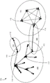
An example of CPCI usage is illustrated in fig. 2 in further corresponding detail in table 3. Fig. 2 illustrates an exemplary scenario for context-related power control management. P2PNW 101 (i.e., oval 101) includes multiple peers that communicate using centralized group communication.
The peer may be a tablet, a smart phone, a music player, a game console, a personal digital assistant, a laptop, a PC, a medical device, a networked car, a smart meter, a home gateway, a monitor, an alarm, a sensor, a set-top box, a printer, a Mobile Station (MS) in a 2G network, a User Equipment (UE) in a 3G network, or one or a group of Full Function Devices (FFDs) or Reduced Function Devices (RFDs) in an IEEE802.15 (wireless personal area network (WPAN)) network. As one example, a peer may have the hardware architecture illustrated in fig. 12C (described more fully below), or a variation thereof, or may have the computing system architecture illustrated in fig. 12D (also described more fully below).
Still referring to fig. 2, the peers in P2PNW 101, such as peer 110, peer 113, peer 116, and peer 117, communicate with each other via several decentralized CPCI management aggregation points, hereinafter referred to as virtual leaders. A virtual leader (e.g., peer 116) is a peer that can be dynamically selected to represent, manage, and coordinate P2P communications among a group of peers (i.e., in a P2PNW) that share the same ProS for centralized control within the P2 PNW. A super virtual leader (not shown) is a virtual leader defined to coordinate all virtual leaders of neighboring P2 PNWs for centralized control among the P2 PNWs. The virtual leader and the super virtual leader may be used for purposes of synchronization, power control, interference management, channel allocation, access control, and so forth.
Each P2PNW in fig. 2 may have a different ProS implemented. For example, peers within P2PNW 101 may communicate with each other using video conferencing ProS. As another example, peers within P2PNW 102 may communicate with each other using chat ProS and may be incorporated into a pair-wise communication. Peers within P2PNW 103 may communicate with each other using the keep-alive ProS and may be incorporated into the pair-wise communication. Peers within P2PNW 104 may communicate with each other using game ProS and may be incorporated into distributed group communications. In distributed group communications, each peer of the P2PNW manages all control-related communications with other peers in proximity to the P2PNW, which may communicate on a common channel, a broadcast channel, a paging channel, and so forth.
Thus, in the example of fig. 2, the ProS of P2PNW 101, P2PNW 102, P2PNW 103, and P2PNW 104 have peers with different contexts. As illustrated in table 3, the ProS shown in fig. 2 may have different recommended context information and power control information settings. As described in more detail below, understanding the context of different pross may allow for optimization of transmit power to support a preferred quality of service level for the ProS, while minimizing wireless radio interference and power loss, among other things.
TABLE 3

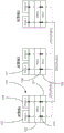
As illustrated in fig. 3, CPCI may be managed across multiple layers, which may include a service layer 120, a MAC layer 122, and a physical layer 121. Above the service layer 120 there may be an application layer. In one embodiment, the CPCI may be maintained at the service layer 120 or an application layer (not shown) of the default CPCI and at the physical layer 121 or the MAC layer 122. The ProS may be located at the service layer 120 or at an application layer (not shown) above the service layer 120. In fig. 3, ProS 123 may update CPCI based on detection information or measurement results at power control function 125 located at physical layer 121 during transmit and receive sessions. The power control function of the device is a hardware and/or software module executing on a processor of the device that controls the transmission power of a transmitter of the device. The updated CPCI value at the power control function 125 may be fed back to higher layers, such as the ProS 123 of the service layer 120. As also shown in fig. 3, CPCI may also be exchanged at a low layer between peers for context related control to ensure reliable proximity services. The power control function 125 associated with the ProS 123 may communicate with the power control function 126 of the physical layer 128. Power control functions may be implemented at either physical layer 121 or MAC layer 122 in order to minimize latency and meet any latency requirements. Some or all of the power control functions may be at the service layer 120 or application layer, for example defining default parameter values based on, among other things, the power control values of the ProS and the lower layers (e.g., MAC or PHY) covered.
The following discloses a scheme for cross-layer management of CPCI and exchange of CPCI between nearby peers. Context-related power control may enable more reliable and efficient IoT proximity services. The roughly described context-related power control mechanisms may include general context-related power control, context-related multi-application power control, and context-related point-to-multipoint power control within a P2 PNW. General context-related power control, context-related multi-application power control, and context-related P2PNW intra-point-to-multipoint power control may involve CPCI detection, inter-P2 PNW power control, intra-P2 PNW power control, and CPCI management.
Fig. 4 illustrates an exemplary method for general context-related power control according to one embodiment. At step 131, the default CPCI is passed to the power control function of the peer. The power control function may receive a default CPCI from a service layer (or other layer such as an application layer) on the first peer that is preconfigured (e.g., manually configured by a user or automatically configured by the application or service layer upon initial activation of the first peer or ProS) or updated from a previous session (e.g., automatically updated during a previously connected ProS session). At step 132, the first peer receives CPCI from neighboring peers by scanning channels such as beacon, paging, or broadcast channels. In the case where no adjacent CPCI is detected, a default minimum TxP or a history-based TxP (e.g., a previous average or mean TxP) or a default value based on a power control category (PCat) may be used. At step 133, the first peer determines a first TxP. Here, the first peer may determine the first TxP level based on a default CPCI value passed from a higher layer (e.g., step 131) and CPCI values received from neighboring peers (e.g., step 132).
With continued reference to fig. 4, at step 134 the first peer broadcasts a power control request or piggybacks with a control or data transmission at a first TxP at a common channel. At step 135, the first peer receives a response from a neighboring second peer that may include the CPCI of the second peer (e.g., the CPCI may have power adjustments (PAdj) and other CPCIs for the first peer). The second peer may send more than one CPCI, which may be associated with each proximity service on the second peer or on a group of peers managed by the second peer if the second peer is a virtual leader. At this step, the second peer (which also applies to multiple peers) only needs to be in proximity and does not have to use the same ProS as the first peer for inter-P2 PNW power control. At step 136, based on the updated CPCI, the first peer recalculates TxP using the power control function and adjusts its TxP accordingly, which process generates a second TxP for the first peer. At step 137, after using the inter-P2 PNW association TxP of step 136 (i.e., the second TxP), the first peer may receive a CPCI associated with a first ProS for intra-P2 PNW power control on the first peer. At step 138, the second TxP may be adjusted to a third TxP based on the first ProS-related CPCI received at step 137. When multiple peers are involved, searching for the first peer can consider the CPCI received from each peer and adjust the TxP suitable for ProS. For example, if there are multiple peers, the first peer may average or use the maximum or minimum of its best TxP computed for each peer.
Still referring to fig. 4, step 132 may be considered a CPCI detection step. Steps 133 to 136 may be regarded as inter-P2 PNW power control steps. And steps 137 and 138 may be considered as intra-P2 PNW power control steps. CPCI detection, inter-P2 PNW power control, and intra-P2 PNW power control information call flow are discussed in more detail below.
Fig. 5 illustrates a system 140 similar to fig. 2 including peers in proximity to each other, where CPCI may be used for context-related power control. Fig. 5 illustrates the P2PNW of each ProS utilized by a peer using an oval diagram. The ellipses should not be interpreted as radio ranges of peers etc. Peer 146 utilizes the P2PNW for ProS 141 and utilizes the P2PNW for ProS142, peer 147 utilizes the P2PNW for ProS 141 and utilizes the P2PNW for ProS 143, and peer 145 utilizes the P2PNW for ProS 144. As shown, both peer 146 and peer 147 utilize the P2PNW for ProS 141. Peer 145 may communicate with one or more other peers (not shown) within the P2PNW for ProS 144. Peer 146 and peer 147 may also communicate with one or more other peers (not shown) within the P2PNW for ProS142 and the P2PNW for ProS 143, respectively.
Fig. 6 illustrates an exemplary call flow 150 that contemplates the use of CPCI detection in the system 140 of fig. 5. As shown in fig. 6, peer 146 includes ProS 141 and power control function 152. At step 157, ProS 141 on peer 146 (block 151) sends the CPCI to the power control function 152 associated with ProS 141 on peer 146. The CPCI of step 157 may be a default CPCI value that is pre-configured or updated from previous sessions. For other layers, it is possible to store and send default CPCI values. At step 158, peer 146 detects CPCI from various sources, such as block 153 (ProS 142 on peer 146), block 154 (ProS 141 on peer 147), block 155 (ProS 143 on peer 147), and block 156 (ProS 144 on peer 145). Peer 146 may detect CPCI by scanning beacons, paging, broadcast channels, and the like. The received CPCI of step 158 may include information associating the CPCI with a particular ProS and peer.
At step 159, peer 146 may determine its initial TxP based on the default CPCI value (step 157), the detected CPCI value (step 158), and the measured CPCI value (e.g., measured RxSQ — not shown). The TxP may be based on an average of received TxP for the received CPCI, or use a MinTxP default CPCI value if no CPCI is received from another peer or ProS. The use of steps 157 and 158 may be based on ProS 141 of peer 146 being enabled again after an idle time period (e.g., without using ProS 141) for a predetermined extended time period. In addition, CPCI management processing for inter-P2 PNW power control (shown at 160) and CPCI management processing for intra-P2 PNW power control (shown at 161) may be performed after steps 157 through 159 are completed. It should be noted that the peers in fig. 6 and other figures may be VLs or super VLs.
Fig. 7 is an exemplary call flow diagram providing further details of CPCI management processing 160 for inter-P2 PNW power control in the context of system 140, according to one embodiment. During inter-P2 PNW CPCI management, peers may cooperate with neighboring peers by exchanging CPCI on common channels. At step 171, peer 146 broadcasts (on a common channel) a power control request message (PCReq) associated with ProS 141. The PCReq may include a CPCI associated with ProS 141 of peer 146. The PCReq may be sent to a neighboring peer, but need not join the same P2PNW for ProS 141.
At step 172, peer 146 receives responses (e.g., power control responses) that include CPCI from various nearby peers, such as block 153 (ProS 142 on peer 146), block 154 (ProS 141 on peer 147), block 155 (ProS 143 on peer 147), and block 156 (ProS 144 on peer 145). At step 173, peer 146 adjusts TxP based on the received response of step 172. CPCI may be exchanged and updated at lower layers (e.g., PHY or MAC) and then sent to higher layers (e.g., service or application layers above TCP/IP in OSI model for infrastructure-based communication systems or above MAC layer without TCP/IP layer for infrastructure-less wireless systems).
Fig. 8 is an exemplary call flow diagram for providing further details of process 161 for CPCI management for intra-P2 PNW power control in the context of system 140, according to one embodiment. Here, CPCI associated with ProS 141 is exchanged between peers 146 and 147 operating within the same P2PNW for ProS 141. At step 185, peer 146 sends a power control request (PCReq) with CPCI related to ProS 141 on peer 146 to peer 147 at a predetermined first TxP. The first TxP may be based on a default CPCI value, a "CPCI detection" derived CPCI, a P2PNW management derived TxP, and so on. At step 187, peer 147 adjusts to the second TxP and updates its CPCI based on the CPCI received at step 185. At step 188, the updated CPCI of step 187 may be sent to a higher layer of peer 147 (e.g., an application layer associated with ProS 141). At step 189, peer 147 sends a power control response (PCRe) at the second TxP. The PCRe of step 189 may include the updated CPCI of step 187.
At step 190, peer 146 tunes to the third TxP and updates its CPCI based on the CPCI received at step 189. At step 191, peer 146 sends a control or data message at the third TxP. 191 may include the updated CPCI of step 190. At step 192, the updated CPCI of step 190 may be sent to a higher layer of peer 146 (e.g., an application layer associated with ProS 141). At step 193, peer 147 updates its CPCI based on the received CPCI of step 191, and at step 194, the updated CPCI is sent to higher layers. At step 195, peer 147 sends peer 146 a positive acknowledgement of the message of step 191 that peer 147 received. Periodically, CPCI may be sent and TxP adjusted based on a predetermined time, such as PCInt. In one embodiment, if peer 146 sends a PCReq and does not receive a timely response (e.g., PCRe), then the TxP power may be incrementally adjusted and the PCReq may be sent again until PCRe is received, a predetermined timeout number is reached, and so on.
As discussed herein, a peer can join one or more P2 PNWs in the neighborhood at the same time. For example, referring to fig. 5, peer 146 can interact with peer 147 via chat using ProS 141 and can check for advertisements or coupons broadcast from the store by another peer (not shown) associated with ProS 142. In this example, CPCI may need to be managed across applications on the device. When providing context-related power control across multiple applications on a single peer, CPCI detection and inter-P2 PNW power control management are similar to those discussed in fig. 6 and 7, respectively. Intra P2PNW power control will be similar to that discussed with respect to fig. 8, but with complex added layers. For example, peer 146 adjusts the TxP of each transmission to fit the determined TxP for the particular ProS used in that transmission (e.g., different TxP for chat ProS and advertising ProS). More details are discussed below.
Fig. 9 illustrates an exemplary method of CPCI management for multi-application power control within a P2PNW from the perspective of a peer 146 of the system 146. At step 201 and step 202, peer 146 starts context-related power control for ProS 141 and ProS142, respectively. Step 202 and step 203 may be triggered by an indication that a transmission needs to occur for the ProS. The indication may be a user command or an automatic occurrence based on conditions such as time or receiving data from a peer or other device. The indication may follow an initial startup of the PRoS after an idle time based timeout, a device reboot, or the like. At step 203 and step 204, CPCI detection may be used for ProS 141 and ProS142, respectively. At step 205 and at step 206, inter-P2 PNW management may be used for ProS 141 and ProS142, respectively. At step 207, peer 246 determines whether ProS 141 requires a transfer. If so, at step 209, in such an implementation, the context-related power control procedure in the MAC/PHY layer for ProS 141 is applied and transmission occurs. After the transmission, at step 211, peer 146 determines whether ProS142 requires a transfer. If so, at step 219, in such an implementation, context-related power control procedures in the MAC/PHY layer for the ProS142 are applied and transmission occurs. If not, peer 146 continues to send transmissions based on the context-related power control process in the MAC/PHY layer for ProS 141. As shown in fig. 9, similar transmission analysis related to context-related power control procedures in the MAC/PHY layers for ProS 141 and ProS142 will continue at peer 146 until the context-related power control is relinquished.
Many pross are based on group communication via broadcast or multicast, such as ProS conferencing with current speakers or gateways managing parking meters for small parking lots. As described above, point-to-multipoint intra-P2 PNW CPCI management is similar to CPCI management for intra-P2 PNW multi-application power control, except that a central peer may multicast CPCI to multiple peers instead of unicasting CPCI to each peer. The following are more detailed examples.
Fig. 10 illustrates an exemplary method 230 for one-to-many communication for context-related power control with reference to system 140 of fig. 5. At step 231, peer 146 broadcasts or multicasts a power control request to neighboring peers with ProS 141. The power control request includes a transmit power level (e.g., in dBm) and a location (e.g., an absolute or relative geographic location). At step 232, peer 147 (the nearest receiver) replies with its power control response including the transmit power level (i.e., in dBm) and the location (i.e., absolute or relative geographic location). In this example, there is also a peer (not shown) that is further away from peer 146 than peer 147. All peers respond to peer 146. At step 233, peer 146 evaluates the received CPCI and determines power adjustments for peer 147 and each other peer based on path losses computed from the received CPCI. At step 234, peer 146 determines a transmission level based on the power control class or QoS of the service or application. In this example, there may eventually be three quality of service levels used. There may be a guaranteed quality of service defined as the transmit power +1/4dB from the previous power for communications with the peer furthest from peer 146. There may be a best effort quality of service defined as transmit power-1/4 dB previous power for communicating with peer 147 (a nearby receiver). Finally, there may be an average quality of service defined as transmit power-previous power + average power adjustment for communication between all other peers.
Context information and power control information are briefly discussed in tables 1 and 2 above. More details regarding context information and power control information are provided below. As described above, the context information may include information such as a service power class (SPcat), a service range (SerR), a power control interval (PCInt), a Bandwidth (BW), a Data Rate (DR), a Modulation and Coding Scheme (MCS), a latency (Lat), a location (Loc), a speed (Sd), and the like.
Spcat is a predetermined value that indicates the class of power control requirements of different types of ProS, such as public safety, healthcare, social networking, commercials, sensor networks, or smart offices, among others. The categories may be defined using numeric, alphabetic, or alphanumeric values. For example, a first category (e.g., SPcat ═ 1) may be created for pross that may require high data rates and high quality of service and other constraints or preferences, and a second category (e.g., SPcat ═ 2) may require low data rates and low quality of service. For example, the healthcare ProS may be defined as SPcat 1, while the sensor network and chat application may each be defined as SPcat 2. SPcat may be used to set the default power control scheme. For example, when the ProS is first initialized, default TxP and other power control parameters may be set. This default scheme may be adjusted to receive and analyze context information and power control information at the peer.
SerR is context information that can be defined as a typical serving radio range (i.e., distance) that is recommended for a predetermined appropriate quality of service of the ProSP2 PNW. The service scope can vary based on different pross. For example, the SerR between peers for public safety ProS may be 2 kilometers, while the SerR between peers for intelligent residential proximity services may be 120 meters.
PCInt is context information that can be defined as a period for updating or exchanging CPCI and a period for adjusting a transmission power level. For example, PCInt may be a relatively large value for ProS P2PNW with very low mobility or no mobility, in order to save overhead of CPCI exchange between transmitter and receiver, while PCInt may be a relatively small value for ProS P2PNW with high mobility. Speed may be a factor in determining PCInt. The PCInt may be considered as power control information or context information because it is a period for updating the CPCI or adjusting the transmission power level.
BW, DR and MCS are typically associated with each other. BW is context information that may be defined as the bandwidth (e.g., Mbit/s) or subcarriers (e.g., resource blocks) allocated for peers in the ProS P2 PNW. The BW may be a typical BW to ensure that a proper quality of service is reserved or a BW available to the peer. Typically, the bandwidth is allocated commensurate with the data rate ProS and signal strength to ensure the required or recommended throughput. DR may be defined as a typical data rate to ensure a predetermined appropriate quality of service of the ProS, and may be defined as a measured data rate of the peer. MCS may be defined as a modulation and coding scheme for ProS, such as different methods for Quadrature Amplitude Modulation (QAM), Phase Shift Keying (PSK), Amplitude Shift Keying (ASK), and so on. Higher modulation and coding schemes may involve high data rates ProS, which may require higher maximum transmit power to ensure the required throughput.
Lat can be defined as the delay tolerance of ProS. For example, emergency-related ProS may require very low Lat (e.g., milliseconds), while keep-alive-related proximity services may be able to tolerate high Lat (e.g., seconds or minutes). Latency requirements may affect the power control interval (PCInt). For low latency services or applications, the PCInt value may be relatively small compared to high latency services or applications.
Loc may be defined as the location of a peer for proximity services, such as geographic location, displacement from another location (e.g., 50 northwest of P2PNW), and so on. Loc may be an absolute position (e.g., latitude and precision) or a relative position with respect to the peer. Loc can be used to estimate the path loss. For a fully distributed and infrastructure-less wireless system, there is no central controller for managing transmit power control, such as an NB or eNB in a 3GPP cellular system. Thus, the peer may estimate the transmit power level based on path losses derived from the locations and transmit power levels of other transmitters and the received signal strength.
Sd may be defined as a peer-typical speed that ensures a predetermined appropriate quality of service for the ProS P2 PNW. Sd may also be defined as the measured speed of the peer. For example, a car on a highway may be traveling at a high speed and may cause greater channel variations, which may require relatively frequent power adjustments, i.e., lower PCInt values, than hiking speed. For some ProS, higher speeds may also result in performance degradation, which may require higher transmit power to ensure throughput performance. The measured speed may be used to define PCInt.
The power control information described herein may include information such as transmit power (TxP), maximum transmit power (MaxTxP), minimum transmit power (MinTxP), power adjustment (PAdj), End Point (EP), Path Loss (PL), received signal quality (RxSQ), and the like.
TxP may be a typical power level (e.g., dbm) that may ensure a predetermined appropriate quality of service for the ProS P2PNW, or may also be defined as TxP measured at a particular time. This value may be adjusted during closed loop power control. MaxTxP is the maximum power level allowed for ProS P2PNW transmission that can ensure a predetermined appropriate quality of service for ProS P2PNW, or MaxTxP available to the transmitter. If the transmitter reaches its MaxTxTxP value, the transmitter can no longer increase the transmit power level, even if the calculated power is adjusted to "power up" during open or closed loop power. MinTxP is the minimum power level required for ProS P2PNW transmission that can ensure a predetermined appropriate quality of service for the ProS P2PNW, or the MinTxP available to the transmitter. Typically, the transmitter starts transmitting at its MinTxP if there is not enough other information to estimate the initial power level.
PAdj is a power adjustment used for initial, closed-loop, or open-loop context-related power control. PAdj may be a relative value (e.g., reduced by.5 db) based on the current power level or an instruction to transmit within a range (e.g., less than 10 dbm).
An EP is an endpoint (i.e., receiver) in a group-based communication of one-to-many broadcast/multicast or one-to-one unicast within a group. The EP value may be an EP identifier (e.g., peer or device identifier) that is locally unique within the P2 PNW. The EP can map from the MSISDN to a locally unique shorter ID, or other peer or device identifier.
Other power control information may be PL and RxSQ. PL is the attenuation or transmission loss through the radio channel. PL is used to estimate the initial power level or to calculate the next power adjustment. PL may be a relative value such as 10 db. RxSQ may be used to estimate the initial power level or to calculate the next power adjustment. RxSQ may be indicated by a measured Received Signal Strength Indicator (RSSI), a received signal to interference and noise ratio (SINR), or a Channel Quality Indicator (CQI).
As described herein, CPCI may be a class indication that represents a range rather than an absolute value. For example, Sd may be a category such as "hiking speed" indicating a speed of 1 to 5 kilometers per hour. Alternatively, Sd may be an absolute value such as 4.75 kilometers per hour, for example. The category and absolute value concepts may be applied to Loc, MCS, Lat, DR, BW, PCInt, and SerR, as well as other context information or power control information. The CPCI may be updated based on historical data.
As described above in connection with fig. 1, CPCI may be communicated between peers in a variety of ways. In addition to the options illustrated in fig. 1, in other embodiments, modified or extended IEEE802.15 or 802.11MAC frames may be employed to facilitate transmission of CPCI as well as new Information Elements (IEs). In one embodiment, a new frame format may be used, which may be a generic MAC frame with a new field in the MAC header that is relevant to context information that facilitates the power control process described herein. New management frames may also be used to support power control requests and responses. Further details regarding these frames and IEs are provided below.
Fig. 11A illustrates one embodiment of a modified MAC frame format 400 that may be used in conjunction with the power control processes described herein. In fig. 11A and 11B, the fields indicated in bold, italics, and underline are new or modified fields and may include new subfields. The other fields may have the same meaning as defined in the existing ieee802.15.4 and 802.11 standards.
As shown, the frame 400 generally includes a MAC header 402 and a MAC payload 404. In one embodiment, all fields in the frame except the auxiliary field 416 and the auxiliary security header 418 may be required. In one embodiment, the sequence number field 408 and the secondary security header 418 may have the same meaning as defined in the ieee802.15.4 standard.
In this embodiment, the frame control field 406 carries control information such as the frame type, the type of positive information required, and the addressing mode. Fig. 11B illustrates one embodiment of a format 500 for a frame control field. In one embodiment, the frame type, frame pending, security enabled, and IE present fields may have the same meaning as defined in the IEEE802.15.4 standard. In one embodiment, all of such frame control fields 406 may be mandatory.
The frame type and subtype fields 424, 426 may be mandatory and may together indicate the type of frame, i.e., the function of the frame. In one embodiment, there are four basic frame types: beacon, management, data, and positive. Each type of frame may have several subtypes. In addition, the meaning of the subtype field may vary for different frame types. In one embodiment, a management frame may have a frame type value of "1" and a frame subtype value of "8" may be used to identify the frame as a "power control request" frame, and a frame subtype value of "9" may be used to identify the frame as a "power control response" frame. Other frame subtype values may be used to identify other types of management frames.
Still referring to fig. 11B, in one embodiment, the required ACK type field 428 in the frame control field 406 may specify which type of positive frame is desired. For example, the required ACK type field may be set as shown in table 4 below.
| Required ACK type value | Type of ACK required |
| 0 | No |
| 1 | |
| 2 | |
| 3 | Conditional ACK |
| 4 | Group ACK |
| 5 | Cross-layer ACK |
| 6 | Cross-application ACK |
| 7 | Cross-layer and cross-application ACK |
| 8 | Fragment Increment ACK (IACK) |
TABLE 4 value of ACK type field 428 required
Referring back to fig. 11A, the addressing field may consist of one or more of the following: a source address, a destination address, a transmit hop address, and a receive hop address. The source and destination address fields may carry the source and destination addresses of the frame. Transmit hop address and receive hop address fields carrying address information of intermediate peers may be reserved for multi-hop scenarios. The transmit hop address is the address of the peer that sent the frame. The receive hop address is the address of the peer that will receive the frame. The presence of the transmit hop address and/or receive hop address fields may be indicated by an addressing field indication.
As shown in fig. 11A, MAC frame format 400 may also include an addressing field indication field 410, which may contain an indication that there is a transmit hop address and a receive hop address in addressing field 412. While both source and destination addresses may always be present in the addressing field 412, the presence of transmit and receive hop addresses may be optional for multi-hop scenarios. For example, for a one-hop transmission, neither exists, for the first hop in a multi-hop transmission (i.e., the original source is sending the frame), only the receive hop address exists and the transmit hop address is the same as the source address, for the last hop in the multi-hop transmission, only the transmit hop address exists and the receive hop address is the same as the destination address, and for the other hops in the multi-hop transmission, both the transmit hop address and the receive hop address are included. In addition, when the addressing field indication is established as in the last two examples (last hop and other hops), the frame may be a relay frame.
As further shown in FIG. 11A, the P2PNW/APP ID field 414 field may contain a P2P network ID or application ID. All peers joining the P2P Network (NW) may have a locally unique P2PNW/APP ID. This field may carry the application ID if the P2PNW ID is not determined at the time of transmitting the frame. Because the P2PNW may be formed by an application or service, the P2PNWID may be a network identifier that may be used to define and distinguish application-specific P2 PNWs. Due to the distributed nature of proximity services, the P2PNW ID may be locally unique.
The P2PNW ID may include, but is not limited to: a CAID or application ID indicating the required service or application (e.g., Facebook for social networks, Netflix for video streams, etc.), location information indicating the location of the P2PNW, the ID of the peer generating the P2PNW ID, and a network sequence number that can be used to distinguish an existing P2PNW from the same context information. The P2PNW ID may be generated using different structures, such as a concatenated structure in which each information block is assigned some information bits and all information blocks are concatenated, or a parallel structure in which all information blocks are summed together by some mathematical computation, such as XOR and hash algorithms.
The P2PNW ID may be generated and assigned by different parties in the network based on different control schemes. In a centralized control scheme embodiment, the P2PNW ID may be generated by the supervl and then notified to the VL, or the VL may generate the P2PNW ID and broadcast the P2PNW ID in a beacon to notify the supervl and other VLs. In a hybrid control scheme embodiment, a VL may generate a P2PNW ID and broadcast the P2PNW ID in a beacon to inform other VLs. In a distributed control scheme embodiment, peers that want to form a P2PNW (i.e., peers that define a new application frame) may generate a P2PNW ID and broadcast a beacon to notify each peer that is in the vicinity of the P2PNW ID.
Still referring to fig. 11A, the auxiliary field 416 may contain fields that are optional but important for some functions. For example, a context category field may be included that indicates a category of application or service, such as an emergency service, social network, intelligent office, and the like. As another example, a hop (hop) indication field indicating whether the frame sender wants to relay other frames for the multi-hop discovery process may be included.
As mentioned above, a power control request frame (e.g., frame type 1; frame subtype 8) may be used to request neighboring context and power control information. Table 5 lists some exemplary additional fields that may be provided in the MAC payload of a power control request frame (e.g., frame payload field 422 of MAC payload 404 of frame format 400), according to one embodiment. In one embodiment, the information in table 5 may be exchanged only once in the neighborhood. Only when any part of this information changes is it included in the power control request for information exchange. As described further below, other power control related information such as service power class, transmission power, and received signal quality may be included in one or more CPCI IEs.

TABLE 5 fields in an example Power control request frame
In one embodiment, the power control response may be sent when the peer receives the power control request message. As described above, the power control response message may provide the requester with power control information of the peer that received the power control request. The information included within the power control response message is similar to the information provided in the power control request.
An Information Element (IE) may provide a flexible, extensible, and easy to implement way to encapsulate information for efficient information exchange. The IE may be part of the MAC header or MAC payload. In the example frame format 400 illustrated in fig. 11A, a field 420 is provided for holding an IE. Multiple IEs may be concatenated in one frame.
Table 6 below lists example fields for carrying the IE of the CPCI in the power control request or response frame.

TABLE 6 fields in CPCI IE
In other embodiments, CPCI information may be carried in 802.15 or 802.11 beacon frames with new or modified fields similar to those illustrated in fig. 11A.
Fig. 12A is a communication system 10 of an example machine-to-machine (M2M), internet of things (IoT), or network of things (WoT) in which one or more disclosed embodiments may be implemented. In general, M2M technology provides building blocks for IoT/WoT, and any M2M device, gateway, or service platform may be a component of IoT/WoT, and IoT/WoT service layer, among others.
As shown in fig. 12A, the M2M/IoT/WoT communication system 10 includes a communication network 12. The communication network 12 may be a fixed network (e.g., Ethernet, Fiber, ISDN, PLC, etc.) or a wireless network (e.g., WLAN, cellular, etc.) or a network of heterogeneous networks. For example, the communication network 12 may include a multiple access network that provides content, such as voice, data, audio, messaging, broadcast, etc., to a plurality of users. For example, communication network 12 may employ one or more channel access methods, such as Code Division Multiple Access (CDMA), Time Division Multiple Access (TDMA), Frequency Division Multiple Access (FDMA), orthogonal FDMA (ofdma), single carrier (SC-FDMA), and so forth. Further, for example, the communication network 12 may include other networks such as a core network, the internet, a sensor network, an industrial control network, a personal area network, a converged personal network, a satellite network, a home network, or an enterprise network.
As shown in fig. 12A, the M2M/IoT/WoT communication system 10 may include an infrastructure domain and a field domain. The infrastructure domain refers to the network side of the end-to-end M2M deployment, and the field domain refers to the local area network, typically behind the M2M gateway. The field domain includes the M2M gateway 14 and the terminal device 18, which may be peers as described above. It should be appreciated that any number of M2M gateway devices 14 and M2M terminal devices 18 may be included in the M2M/IoT/WoT communication system 10 as desired. The M2M gateway devices 14 and the M2M terminal devices 18 are each configured to transmit and receive signals via the proximate communication network 12 or direct radio link. The M2M gateway device 14 allows wireless M2M devices (e.g., cellular or non-cellular) and fixed network M2M devices (e.g., PLC) to communicate via a carrier network such as the communication network 12 or a direct radio link. For example, an M2M device may collect and send data to an M2M application 20 or an M2M device 18 via a proximate communication network 12 or a direct radio link. The M2M device 18 may also receive data from the M2M application 20 or the M2M device 18. Further, as described below, data and signals may be sent to the M2M application 20 via the M2M service layer 22 and received from the M2M application 20. For example, the M2M device 18 and the gateway 14 may communicate via various networks including cellular networks, WLANs, WPANs (e.g., Zigbee, 6LoWPAN, Bluetooth), direct radio links in proximity, and wireline.
Referring to fig. 12B, the M2M service layer 22 in the illustrated field domain provides services to the M2M applications 20, the M2M gateway devices 14, and the M2M end devices 18, as well as the communication network 12. As described herein, the ProS may be an M2M application 20 or an M2M service layer 22. It should be appreciated that the M2M service layer 22 may communicate with any number of M2M applications, M2M gateway devices 14, M2M terminal devices 18, and communication networks 12 as desired. The M2M service layer 22 may be implemented by one or more servers, computers, etc. The M2M service layer provides service capabilities that apply to the M2M terminal devices 18, the M2M gateway devices 14, and the M2M applications 20. The functionality of the M2M service layer 22 may be implemented in a variety of ways, e.g., as a Web server, in a cellular core network, in a cloud, etc.
Similar to the illustrated M2M service layer 22, there is an M2M service layer 22' in the infrastructure domain. The M2M service layer 22 ' provides services to the M2M applications 20 ' in the infrastructure domain and the underlying communication network 12 '. The M2M service layer 22' also provides services to the M2M gateway devices 14 and M2M end devices 18 in the field domain. It should be appreciated that the M2M service layer 22' may communicate with any number of M2M applications, M2M gateway devices, and M2M terminal devices. The M2M service layer 22' may interact with the service layer through different service providers. The M2M service layer 22' may be implemented by one or more servers, computers, virtual machines (e.g., cloud/compute/store, etc.), and so on.
Still referring to fig. 12B, the M2M service layers 22 and 22' provide a core set of service delivery capabilities that various applications and vertical products can utilize. These service capabilities enable the M2M applications 20 and 20' to interact with the device and perform functions such as data collection, data analysis, device management, security, billing, service/device discovery, and the like. In essence, these service capabilities free applications from the burden of implementing these functions, thus simplifying application development and reducing cost and time to market. The service layers 22 and 22 'also enable the M2M applications 20 and 20' to communicate over the various networks 12 and 12 'in conjunction with the services provided by the service layers 22 and 22'.
In some embodiments, as described herein, M2M applications 20 and 20' may include a desired application for communicating CPCI using context-related power control messages that may include PCReq and PCRe. The M2M applications 20 and 20' may include applications in various industries, such as, but not limited to, transportation, health and fitness, home networking, energy management, asset tracking, and security and surveillance. As described above, the M2M service layer operating across devices, gateways, and other servers of the system supports functions such as data collection, device management, security, billing, location tracking/geo-fencing, device/service discovery, and legacy system integration, and provides these functions as services to the M2M applications 20 and 20'.
The proximity service of the present application may be implemented as part of the service layer. The service layer is a software middleware layer that supports value-added service capabilities through a set of Application Programming Interfaces (APIs) and underlying network interfaces. An M2M entity (e.g., an M2M functional entity such as a device, gateway, or service/platform that may be implemented by a combination of hardware and software) may provide an application or service. Both ETSI M2M and oneM2M use a service layer that may include the proximity services of the present invention. The service layer of ETSI M2M is referred to as the Service Capability Layer (SCL). SCL may be implemented within M2M devices (where SCL is referred to as device SCL (dscl)), within gateways (where SCL is referred to as gateway SCL (gscl)), and/or within network nodes (where SCL is referred to as network SCL (nscl)). The oneM2M service layer supports a set of Common Service Functions (CSFs) (i.e., service capabilities). An instantiation of a set of one or more particular types of CSFs is referred to as a Common Services Entity (CSE), which can be hosted on different types of network nodes (e.g., infrastructure nodes, intermediate nodes, application specific nodes). Further, the context-related power control of the present application can be implemented as part of an M2M network using a Service Oriented Architecture (SOA) and/or a Resource Oriented Architecture (ROA) to access proximity services such as the present application.
Fig. 12C is a system diagram of an example M2M device 30, such as the M2M terminal device 18 or M2M gateway device 14 shown in fig. 12A and 12B, or a peer such as any of those illustrated in fig. 2, 3, and 5-9. As shown in fig. 12C, the M2M device or peer 30 may include a processor 32, a transceiver 34, a transmit/receive element 36, a speaker/microphone 38, a keyboard 40, a display/touchpad 42, non-removable memory 44, removable memory 46, a power supply 48, a Global Positioning System (GPS) chipset 50, and other peripherals 52. It should be appreciated that the M2M device 30 may include any subcombination of the above elements while still conforming to an embodiment. The device may be a device that uses the disclosed systems and methods for context-related power control.
The processor 32 may be a general-purpose processor, a special-purpose processor, a conventional processor, a Digital Signal Processor (DSP), a plurality of microprocessors, one or more microprocessors in association with a DSP core, a controller, a microcontroller, Application Specific Integrated Circuits (ASICs), Field Programmable Gate Arrays (FPGAs) circuits, any other type of Integrated Circuit (IC), a state machine, or the like. The processor 32 may perform signal encoding, data processing, power control, input/output processing, and/or any other functions that enable the M2M device 30 to operate in a wireless environment. The processor 32 may be coupled to a transceiver 34, and the transceiver 34 may be coupled to a transmit/receive element 36. Although fig. 12C shows the processor 32 and the transceiver 34 as separate components, it should be understood that the processor 32 and the transceiver 34 may be integrated together in an electronic package or chip. The processor 32 may execute application layer programs (e.g., a browser) and/or radio access layer (RAN) programs and/or communications. Processor 32 may perform security operations such as authentication, security key agreement, and/or encryption operations, such as at the access layer and/or application layer.
The transmit/receive element 36 may be configured to transmit signals to or receive signals from the M2M service platform 22 or another peer. For example, in an embodiment, the transmit/receive element 36 may be an antenna configured to transmit and/or receive RF signals. The transmit/receive element 36 may support various networks and wireless interfaces, such as WLAN, WPAN, cellular networks, and the like. In embodiments, the transmit/receive element 36 may be an emitter/detector configured to, for example, emit and/or receive IR, UV, or visible light signals. In yet another embodiment, the transmit/receive element 36 may be configured to transmit and receive both RF and optical signals. It should be appreciated that the transmit/receive element 36 may be configured to transmit and/or receive any combination of wireless and wired signals.
Additionally, although the transmit/receive element 36 in fig. 12C is shown as a single element, the M2M device 30 may include any number of transmit/receive elements 36. More particularly, the M2M device 30 may employ MIMO technology. Thus, in an embodiment, the M2M device 30 may include two or more transmit/receive elements 36 (e.g., multiple antennas) for transmitting and receiving wireless signals.
The transceiver 34 may be configured to modulate signals to be transmitted by the transmit/receive element 36 and demodulate signals received by the transmit/receive element 36. As described above, the M2M device 30 may have multi-mode capabilities. Thus, the transceiver 34 may include multiple transceivers that enable the M2M device 30 to communicate via multiple RATs, such as UTRA and IEEE 802.11.
The processor 32 may access information from, and store data in, any type of suitable memory, such as the non-removable memory 44 and/or the removable memory 46. The non-removable memory 44 may include Random Access Memory (RAM), Read Only Memory (ROM), a hard disk, or any other type of memory storage device. The removable memory 46 may include a Subscriber Identity Module (SIM) card, a memory stick, a Secure Digital (SD) memory card, and so forth. In other embodiments, the processor 32 may access information from, and store data in, a memory that is not physically located on the M2M device 30 (such as on a server or home computer). Processor 32 may be configured to control an illumination pattern, image, or color on display or indicator 42, or otherwise indicate the status of context-related power control propagation or processing, in response to whether context-related power control (e.g., CPCI information and updates, including status such as whether CPCI detection, inter-P2 PNW power control, or intra-P2 PNW power control occurred) in some embodiments described herein is successful or unsuccessful.
The processor 32 may receive power from the power supply 48 and may be configured to distribute and/or control power to other components in the M2M device 30. The power supply 48 may be any device suitable for powering the M2M device 30. For example, power source 48 may include one or more dry cell batteries (e.g., nickel cadmium (NiCd), nickel zinc (NiZn), nickel metal hydride (NiMH), lithium ion (Li-ion), etc.), solar cells, fuel cells, and the like.
The processor 32 may also be coupled to a GPS chipset 50 configured to provide location information (e.g., longitude and latitude) regarding the current location of the M2M device 30. It should be appreciated that the M2M device 30 may obtain location information by any suitable location determination method while still remaining consistent with an embodiment.
The processor 32 may also be coupled to other peripherals 52, and the peripherals 52 may include one or more software and/or hardware modules that provide additional features, functionality, and/or wired or wireless connectivity. For example, the peripheral devices 52 may include accelerometers, electronic compasses, satellite transceivers, sensors, digital cameras (for photo or video), Universal Serial Bus (USB) ports, vibrating devices, vibration devices, and the like,A television transceiver, a hand-free earphone, Modules, Frequency Modulation (FM) radio units, digital music players, media players, video game modules, internet browsers, and the like.
Fig. 12D is a block diagram of an exemplary computing system 90 on which the M2M service platform 22 of fig. 12A and 12B, for example, may be implemented. As noted above, some peers may also be implemented in the form of a computing system 90 or the like. The computing system 90 may include computers and servers, and may be primarily controlled by computer readable instructions, which may be in the form of software, stored anywhere or accessed in any manner. These computer readable instructions may be executed within a Central Processing Unit (CPU)91 to thereby cause the computing system 90 to operate. In many known workstations, servers, and personal computers, the central processing unit 91 may be implemented by a single-chip CPU called a microprocessor. In other machines, the central processing unit 91 may include multiple processors. The coprocessor 81 is an optional processor, distinct from the main CPU 91, which performs additional functions or assists the CPU 91. CPU 91 and/or co-processor 81 can receive, generate, and process data related to the disclosed systems and methods for context-related power control, such as receiving CPCI and other context-related power control information on a control plane.
In operation, CPU 91 fetches, decodes, and executes instructions and transfers information to and from other resources via the computer's main data transfer path, system bus 80. Such a system bus connects the components within computing system 90 and defines the medium for data exchange. The system bus 80 typically includes data lines for sending data, address lines for sending addresses, and control lines for sending interrupts and for operating the system bus. An example of such a system bus 80 is a PCI (peripheral component interconnect) bus.
The memory devices coupled to system bus 80 include Random Access Memory (RAM)82 and Read Only Memory (ROM) 93. These memories include circuitry that allows information to be stored and retrieved. The ROM 93 typically includes stored data that cannot be easily modified. The data stored in the RAM 82 can be read or changed by the CPU 91 or other hardware devices. Access to RAM 82 and/or ROM 93 may be controlled by a memory controller 92. The memory controller 92 may provide an address translation function that translates virtual addresses to physical addresses as instructions are executed. The memory controller 92 may also provide memory protection functions that isolate processes in the system and isolate system processes from user processes. Thus, a program operating in the first mode can only access memory mapped by its own process virtual address space; the program cannot access memory within the virtual address space of another process unless memory sharing between processes has been set.
In addition, the computing system 90 may include a peripheral controller 83 responsible for communicating instructions from the CPU 91 to peripheral devices such as a printer 94, keyboard 84, mouse 95, and hard disk drive 85.
The display 86, controlled by a display controller 96, is used to display visual output generated by the computing system 90. Such visual output may include text, graphics, animated graphics, and video. The display 86 may be implemented using a CRT based video display, an LCD based flat panel display, a gas plasma based flat panel display, or a touch panel. The display controller 96 includes the electronic components necessary to generate the video signals that are sent to the display 86.
Further, the computing system 90 may include a network adapter 97, and the network adapter 97 may be used to connect the computing system 90 to an external communication network, such as the network 12 of fig. 12A and 12B.
It should be appreciated that any or all of the systems, methods, and processes described herein may be implemented in the form of computer-executable instructions (i.e., program code) stored on a computer-readable storage medium which, when executed by a machine, such as a computer, server, M2M terminal device, M2M gateway device, peer, etc., perform and/or implement the systems, methods, and processes described herein. In particular, any of the above-described steps, operations, or functions may be embodied in the form of such computer-readable instructions. Computer-readable storage media include both volatile and nonvolatile, removable and non-removable media implemented in any method or technology for storage of information, but such computer-readable storage media do not include signals. Computer-readable storage media includes, but is not limited to, RAM, ROM, EEPROM, flash memory or other memory technology, CD-ROM, Digital Versatile Disks (DVD) or other optical disk storage, magnetic cassettes, magnetic tape, magnetic disk storage or other magnetic storage devices, or any other physical medium which can be used to store the desired information and which can be accessed by a computer.
In describing preferred embodiments of the presently disclosed subject matter, specific terminology is employed for the sake of clarity as illustrated in the figures. However, the claimed subject matter is not intended to be limited to the specific terminology so selected, and it is to be understood that each specific element includes all technical equivalents that operate in a similar manner to accomplish a similar purpose. One skilled in the art will recognize that the disclosed embodiments may be implemented in architectures and systems such as 3GPP, ETSI M2M, oneM2M, MQTT, IRTF SDNRG, IRTF P2PRG, IETF comman, IEEE 802.11, IEEE802.15, IEEE802.16, IEEE802 OmniRAN, and other M2M capable systems and architectures.
This written description uses examples to disclose the invention, including the best mode, and also to enable any person skilled in the art to practice the invention, including making and using any devices or systems and performing any incorporated methods. The patentable scope of the invention is defined by the claims, and may include other examples that occur to those skilled in the art. Such other examples are intended to be within the scope of the claims if they have structural elements that do not differ from the literal language of the claims, or if they include equivalent structural elements with insubstantial differences from the literal languages of the claims.
Claims (15)
1. A mobile device, comprising:
a processor; and
a memory coupled with the processor, the memory having executable instructions stored thereon that, when executed by the processor, cause the processor to perform operations comprising:
executing a plurality of services on a mobile device, the plurality of services including a first service and a second service;
when multiple services are executing on a mobile device at the same time,
obtaining default service information and power control information to control power for transmitting data, wherein the default service information and power control information includes first default service information and power control information for a first service and second default service information and power control information for a second service, wherein the first default service information and power control information is different from the second default service information and power control information;
detecting scanned service information and power control information to control power used for transmitting data, wherein the scanned service information and power control information includes first scanned service information and power control information from a first plurality of mobile devices having a first service, second scanned service information and power control information from a second plurality of mobile devices having a second service, and third scanned service information and power control information from a third plurality of mobile devices having a third service, wherein the first service, the second service, and the third service are different, wherein the scanned service information and power control information are detected from at least one common channel;
measuring signals received from other mobile devices in the vicinity to obtain measured channel information and power information, wherein the measured channel information and power information comprises: first measured channel information and power information to control power from a first plurality of mobile devices having a first service; second measured channel information and power information to control power from a second plurality of mobile devices having a second service; and third measured channel information and power information to control power from a third plurality of mobile devices having a third service, wherein the measured channel information is associated with a measured received signal to interference plus noise ratio, wherein the measured power information is associated with power or path loss;
determining a first initial transmit power of a first service and a second initial transmit power of a second service based on default service information and power control information, scanned service information and power control information, and measured channel information and power information; and
the method further includes communicating to a first plurality of peer devices with a first service in proximity using the determined first initial transmit power, and communicating to a second plurality of peer devices with a second service in proximity using the determined second initial transmit power.
2. The mobile device of claim 1, wherein a mobile device of the first plurality of neighboring mobile devices with the first service is a group leader of the first neighboring serving network, a mobile device of the second plurality of neighboring mobile devices with the second service is a group leader of the second neighboring serving network, and a mobile device of the third plurality of neighboring mobile devices with the third service is a group leader of the third neighboring serving network.
3. The mobile device of claim 1, wherein default service information and power control information are from a higher layer of the mobile device that is preconfigured or stored from previous communication sessions, and wherein the service information comprises a bandwidth, latency, or speed associated with at least a first service of the plurality of services, and the power control information comprises a minimum power or a maximum power.
4. The mobile device of claim 1, the operations further comprising:
sending a first power control request for the first service and a second power control request for the second service to a first plurality of mobile devices having a first service, a second plurality of mobile devices having a second service, and a third plurality of mobile devices having a third service using the first initial transmit power and the second initial transmit power, wherein the first plurality of mobile devices are proximate, wherein the second plurality of mobile devices are proximate, and wherein the third plurality of mobile devices are proximate,
wherein the first power control request comprises a request for first service information and power control information for the first service,
wherein the second power control request comprises a request for second service information and power control information for a second service,
wherein the first service information and the power control information are information for controlling power for transmitting data of the first service, and the second service information and the power control information are information for controlling power for transmitting data of the second service;
based on the sending, receiving a first plurality of responses to the first power control request and a second plurality of responses to the second power control request from the proximate first plurality of mobile devices with the first service, the proximate second plurality of mobile devices with the second service, and the proximate third plurality of mobile devices with the third service, wherein the first plurality of responses or the second plurality of responses comprise first service information and power control information or second service information and power control information, wherein the first service information and power control information or the second service information and power control information comprises power levels and power adjustments for the associated services; and
based on the first service information and the power control information or the second service information and the power control information:
determining a first transmission power for transmitting data for the first service from the mobile device, an
A second transmission power for transmitting data for a second service from the mobile device is determined.
5. The mobile device of claim 1, the operations further comprising:
sending a first power control request for the first service and a second power control request for the second service to a first plurality of mobile devices having a first service, a second plurality of mobile devices having a second service, and a third plurality of mobile devices having a third service using the first initial transmit power and the second initial transmit power, wherein the first plurality of mobile devices are proximate, wherein the second plurality of mobile devices are proximate, and wherein the third plurality of mobile devices are proximate,
wherein the first power control request comprises a request for first service information and power control information for the first service,
wherein the second power control request comprises a request for second service information and power control information for a second service,
wherein the first service information and the power control information are information for controlling power for transmitting data of the first service, and the second service information and the power control information are information for controlling power for transmitting data of the second service;
based on the sending, receiving a first plurality of responses to the first power control request and a second plurality of responses to the second power control request from the proximate first plurality of mobile devices with the first service, the proximate second plurality of mobile devices with the second service, and the proximate third plurality of mobile devices with the third service, wherein the first plurality of responses or the second plurality of responses comprise first service information and power control information or second service information and power control information, wherein the first service information and power control information or the second service information and power control information comprises a power level or power adjustment for the associated service; and
based on the responded first service information and power control information or second service information and power control information:
determining a first transmission power for transmitting data for the first service from the mobile device, an
Determining a second transmission power for transmitting data for a second service from the mobile device;
providing instructions for;
transmitting data for a first service to a first mobile device having the first service at a first transmission power, an
Transmitting data for a second service to a second mobile device having the second service at a second transmission power, wherein the first transmission power and the second transmission power are different, wherein the plurality of services use unicast when executed simultaneously on the mobile device, wherein unicast is a one-to-one communication between two mobile devices having the same service.
6. The mobile device of claim 4, the operations further comprising:
while multiple services are using multicast and are executing simultaneously on a mobile device, instructions are provided for:
transmitting data for a first service to a first plurality of mobile devices having the first service at a first transmission power, and
transmitting data for a second service to a second plurality of mobile devices having the second service at a second transmission power, wherein the first transmission power and the second transmission power are different, wherein the first transmission power is determined based on a quality of service of the first service and the second transmission power is determined based on a quality of service of the second service.
7. The mobile device of claim 6, wherein quality of service corresponds to at least guaranteed service and best effort service.
8. A method for managing power in a wireless network, the method comprising:
executing a plurality of services on a mobile device, the plurality of services including a first service and a second service;
when multiple services are executing on a mobile device at the same time,
obtaining default service information and power control information to control power for transmitting data, wherein the default service information and power control information includes first default service information and power control information for a first service and second default service information and power control information for a second service, wherein the first default service information and power control information is different from the second default service information and power control information;
detecting scanned service information and power control information to control power used for transmitting data, wherein the scanned service information and power control information includes first scanned service information and power control information from a first plurality of mobile devices having a first service, second scanned service information and power control information from a second plurality of mobile devices having a second service, and third scanned service information and power control information from a third plurality of mobile devices having a third service, wherein the first service, the second service, and the third service are different, wherein the scanned service information and power control information are detected from at least one common channel;
measuring signals received from other mobile devices in the vicinity to obtain measured channel information and power information, wherein the measured channel information and power information comprises: first measured channel information and power information to control power from a first plurality of mobile devices having a first service; second measured channel information and power information to control power from a second plurality of mobile devices having a second service; and third measured channel information and power information to control power from a third plurality of mobile devices having a third service, wherein the measured channel information is associated with a measured received signal to interference plus noise ratio, wherein the measured power information is associated with power and path loss;
determining a first initial transmit power of a first service and a second initial transmit power of a second service based on default service information and power control information, scanned service information and power control information, and measured channel information and power information; and
the method further includes communicating to a first plurality of peer devices with a first service in proximity using the determined first initial transmit power, and communicating to a second plurality of peer devices with a second service in proximity using the determined second initial transmit power.
9. The method of claim 8, wherein a mobile device of the first plurality of neighboring mobile devices with the first service is a group leader of the first neighboring serving network, a mobile device of the second plurality of neighboring mobile devices with the second service is a group leader of the second neighboring serving network, and a mobile device of the third plurality of neighboring mobile devices with the third service is a group leader of the third neighboring serving network.
10. The method of claim 8, wherein default service information and power control information are from a higher layer of the mobile device that is pre-configured or stored from a previous communication session, and wherein the service information comprises a bandwidth, latency, or speed associated with at least a first service of the plurality of services, and the power control information comprises a minimum power or a maximum power.
11. The method of claim 8, further comprising:
sending a first power control request for the first service and a second power control request for the second service to a first plurality of mobile devices having a first service, a second plurality of mobile devices having a second service, and a third plurality of mobile devices having a third service using the first initial transmit power and the second initial transmit power, wherein the first plurality of mobile devices are proximate, wherein the second plurality of mobile devices are proximate, and wherein the third plurality of mobile devices are proximate,
wherein the first power control request comprises a request for first service information and power control information for the first service,
wherein the second power control request comprises a request for second service information and power control information for a second service,
wherein the first service information and the power control information are information for controlling power for transmitting data of the first service, and the second service information and the power control information are information for controlling power for transmitting data of the second service;
based on the sending, receiving a first plurality of responses to the first power control request and a second plurality of responses to the second power control request from the proximate first plurality of mobile devices with the first service, the proximate second plurality of mobile devices with the second service, and the proximate third plurality of mobile devices with the third service, wherein the first plurality of responses or the second plurality of responses comprise first service information and power control information or second service information and power control information, wherein the first service information and power control information or the second service information and power control information comprises power levels and power adjustments for the associated services; and
based on the first service information and the power control information or the second service information and the power control information:
determining a first transmission power for transmitting data for the first service from the mobile device, an
A second transmission power for transmitting data for a second service from the mobile device is determined.
12. The method of claim 8, further comprising:
sending a first power control request for the first service and a second power control request for the second service to a first plurality of mobile devices having a first service, a second plurality of mobile devices having a second service, and a third plurality of mobile devices having a third service using the first initial transmit power and the second initial transmit power, wherein the first plurality of mobile devices are proximate, wherein the second plurality of mobile devices are proximate, and wherein the third plurality of mobile devices are proximate,
wherein the first power control request comprises a request for first service information and power control information for the first service,
wherein the second power control request comprises a request for second service information and power control information for a second service,
wherein the first service information and the power control information are information for controlling power for transmitting data of the first service, and the second service information and the power control information are information for controlling power for transmitting data of the second service;
based on the sending, receiving a first plurality of responses to the first power control request and a second plurality of responses to the second power control request from the proximate first plurality of mobile devices with the first service, the proximate second plurality of mobile devices with the second service, and the proximate third plurality of mobile devices with the third service, wherein the first plurality of responses or the second plurality of responses comprise first service information and power control information or second service information and power control information, wherein the first service information and power control information or the second service information and power control information comprises a power level or power adjustment for the associated service; and
based on the responded first service information and power control information or second service information and power control information:
determining a first transmission power for transmitting data for the first service from the mobile device, an
Determining a second transmission power for transmitting data for a second service from the mobile device;
providing instructions for;
transmitting data for a first service to a first mobile device having the first service at a first transmission power, an
Transmitting data for a second service to a second mobile device having the second service at a second transmission power, wherein the first transmission power and the second transmission power are different, wherein the plurality of services use unicast when executed simultaneously on the mobile device, wherein unicast is a one-to-one communication between two mobile devices having the same service.
13. The method of claim 11, further comprising:
while multiple services are using multicast and are executing simultaneously on a mobile device, instructions are provided for:
transmitting data for a first service to a first plurality of mobile devices having the first service at a first transmission power, and
transmitting data for a second service to a second plurality of mobile devices having the second service at a second transmission power, wherein the first transmission power and the second transmission power are different, wherein the first transmission power is determined based on a quality of service of the first service and the second transmission power is determined based on a quality of service of the second service.
14. The method of claim 13, wherein quality of service corresponds to at least guaranteed service and best effort service.
15. A computer-readable storage medium storing computer-executable instructions that, when executed by a computing device, cause the computing device to perform the method of any of claims 8-14.
Applications Claiming Priority (7)
| Application Number | Priority Date | Filing Date | Title |
|---|---|---|---|
| US201361834341P | 2013-06-12 | 2013-06-12 | |
| US201361834335P | 2013-06-12 | 2013-06-12 | |
| US61/834,341 | 2013-06-12 | ||
| US61/834,335 | 2013-06-12 | ||
| US201361837993P | 2013-06-21 | 2013-06-21 | |
| US61/837,993 | 2013-06-21 | ||
| PCT/US2014/042107 WO2014201240A1 (en) | 2013-06-12 | 2014-06-12 | Context and power control information management for proximity services |
Publications (2)
| Publication Number | Publication Date |
|---|---|
| CN105532050A CN105532050A (en) | 2016-04-27 |
| CN105532050B true CN105532050B (en) | 2020-02-18 |
Family
ID=51177153
Family Applications (2)
| Application Number | Title | Priority Date | Filing Date |
|---|---|---|---|
| CN201480039769.2A Active CN105474715B (en) | 2013-06-12 | 2014-06-12 | Context and power control information management for proximity services |
| CN201480039731.5A Active CN105532050B (en) | 2013-06-12 | 2014-06-12 | Context and power control information management for proximity services |
Family Applications Before (1)
| Application Number | Title | Priority Date | Filing Date |
|---|---|---|---|
| CN201480039769.2A Active CN105474715B (en) | 2013-06-12 | 2014-06-12 | Context and power control information management for proximity services |
Country Status (6)
| Country | Link |
|---|---|
| US (2) | US10531406B2 (en) |
| EP (2) | EP3008955A1 (en) |
| JP (4) | JP6250799B2 (en) |
| KR (4) | KR20180095122A (en) |
| CN (2) | CN105474715B (en) |
| WO (2) | WO2014201251A1 (en) |
Families Citing this family (30)
| Publication number | Priority date | Publication date | Assignee | Title |
|---|---|---|---|---|
| CN104105050B (en) * | 2013-04-01 | 2017-11-28 | 电信科学技术研究院 | A kind of implementation method and device of adjacent communication business |
| KR102009745B1 (en) * | 2013-04-05 | 2019-08-13 | 삼성전자주식회사 | Appratus and method for communicating device to device in an wireless network |
| WO2014201251A1 (en) | 2013-06-12 | 2014-12-18 | Convida Wireless, Llc | Context and power control information management for proximity services |
| CN106170969B (en) | 2013-06-21 | 2019-12-13 | 康维达无线有限责任公司 | Context management |
| CN105612732A (en) | 2013-07-10 | 2016-05-25 | 康维达无线有限责任公司 | Context-aware proximity services |
| EP3100553A4 (en) * | 2014-01-28 | 2017-08-16 | Telefonaktiebolaget LM Ericsson (publ) | Method and apparatus for coordinating resources between different types of communications |
| CN104568090A (en) * | 2014-12-31 | 2015-04-29 | 广州安必平医药科技股份有限公司 | Reagent monitoring system and method based on Internet of Things |
| WO2017051863A1 (en) * | 2015-09-24 | 2017-03-30 | 株式会社Nttドコモ | User device and transmission method |
| KR102418668B1 (en) * | 2015-12-15 | 2022-07-12 | 삼성전자 주식회사 | Electronic apparatus, system for internet of things environment and control method thereof |
| WO2017143570A1 (en) * | 2016-02-25 | 2017-08-31 | 深圳市大疆创新科技有限公司 | Method and device for device authentication, authentication device, unmanned aerial vehicle and remote controller |
| US10139892B2 (en) * | 2016-02-29 | 2018-11-27 | At&T Mobility Ii Llc | Facilitating power conservation for devices based on likelihood of power usage level |
| US10660017B2 (en) * | 2016-04-22 | 2020-05-19 | Telefonaktiebolaget Lm Ericsson (Publ) | First communications device, a second communications device and methods therein for device-to-device communication |
| CN107371119A (en) * | 2016-05-13 | 2017-11-21 | 索尼公司 | Electronic installation, message processing device and information processing method |
| US10667220B2 (en) | 2016-06-07 | 2020-05-26 | Carrier Corporation | System and method for adjusting power in a wireless sensor |
| CN109644089B (en) | 2016-06-15 | 2022-04-26 | 康维达无线有限责任公司 | Unlicensed uplink transmission for new radio |
| US9998995B2 (en) * | 2016-09-22 | 2018-06-12 | Bae Systems Information And Electronic Systems Integration Inc. | Adaptive power control of localized subnets for reducing self-interference in wireless networks |
| US10932276B2 (en) | 2016-11-03 | 2021-02-23 | Convida Wireless, Llc | Frame structure in NR |
| CN108243227A (en) * | 2016-12-26 | 2018-07-03 | 天津蕊喜科技有限公司 | A kind of Empty nest elderly health monitoring system based on Internet of Things |
| KR101908306B1 (en) * | 2017-01-05 | 2018-10-16 | 엘지전자 주식회사 | Air-conditioner and Method thereof |
| JP7024403B2 (en) * | 2017-12-27 | 2022-02-24 | 株式会社リコー | Communication control devices, wireless communication systems, communication control methods, and programs |
| CN108810094A (en) * | 2018-05-17 | 2018-11-13 | 江苏容源电力设备有限公司 | A kind of electric system based on grid system |
| CN108964996B (en) * | 2018-07-04 | 2021-08-27 | 航天神舟智慧系统技术有限公司 | Urban and rural integrated information grid system and information sharing method based on same |
| EP3858023A1 (en) | 2018-09-27 | 2021-08-04 | Convida Wireless, Llc | Sub-band operations in unlicensed spectrums of new radio |
| CN109348452B (en) * | 2018-12-06 | 2021-08-06 | 广州航海学院 | Method for jointly optimizing broadcast beacon frequency and transmitting power of vehicle-mounted communication terminal |
| US11463963B2 (en) * | 2019-01-10 | 2022-10-04 | Qualcomm Incorporated | Path loss estimation |
| US11063651B1 (en) * | 2020-01-31 | 2021-07-13 | Trakpoint Solutions, Inc. | Method for waking from energy-efficient hibernation |
| US11304137B2 (en) * | 2020-01-31 | 2022-04-12 | Trakpoint Solutions, Inc. | Method for waking from energy-efficient hibernation |
| US11722971B2 (en) * | 2020-03-27 | 2023-08-08 | Qualcomm Incorporated | Techniques for determining sidelink resources for multiple transmission and reception points enabled user equipments |
| CN111736684A (en) * | 2020-07-06 | 2020-10-02 | 研祥智能科技股份有限公司 | CPCI power supply |
| US20230147344A1 (en) * | 2021-11-09 | 2023-05-11 | Panasonic Avionics Corporation | Transmission power control for electronic devices in commercial passenger vehicles |
Citations (1)
| Publication number | Priority date | Publication date | Assignee | Title |
|---|---|---|---|---|
| CN102165840A (en) * | 2008-09-25 | 2011-08-24 | 诺基亚公司 | Synchronization for device-to-device communication |
Family Cites Families (98)
| Publication number | Priority date | Publication date | Assignee | Title |
|---|---|---|---|---|
| JP4387551B2 (en) | 2000-04-27 | 2009-12-16 | Necエンジニアリング株式会社 | Wireless communication system and transmission power control method used therefor |
| US7469297B1 (en) | 2000-08-04 | 2008-12-23 | Intellon Corporation | Mechanism for using a quasi-addressed response to bind to a message requesting the response |
| US7352770B1 (en) | 2000-08-04 | 2008-04-01 | Intellon Corporation | Media access control protocol with priority and contention-free intervals |
| US6650873B2 (en) * | 2000-10-19 | 2003-11-18 | Qualcomm, Incorporated | Techniques for adjusting parameters of a quick paging channel based on network load |
| US7668958B2 (en) | 2001-10-18 | 2010-02-23 | Intel Corporation | Method for discovery and routing using a priori knowledge in the form of application programme within mobile AD-HOC networks |
| US7006483B2 (en) * | 2001-02-23 | 2006-02-28 | Ipr Licensing, Inc. | Qualifying available reverse link coding rates from access channel power setting |
| US7756082B1 (en) | 2001-09-07 | 2010-07-13 | Atheros Communications, Inc. | Wireless LAN using background scanning technique |
| US20030212827A1 (en) | 2002-05-08 | 2003-11-13 | Abheek Saha | Method and system for providing peer-to-peer exchange of terminal information over a meshed network |
| US7730208B2 (en) | 2002-05-09 | 2010-06-01 | Hughes Network Systems, Inc. | Method and system for centrally exchanging terminal information over a meshed network |
| JP3574446B2 (en) * | 2002-09-19 | 2004-10-06 | 松下電器産業株式会社 | Transmission power control method and base station apparatus |
| JP2005057602A (en) | 2003-08-06 | 2005-03-03 | Toyota Industries Corp | Program for power management, power management method, and terminal device |
| US8824582B2 (en) | 2003-08-08 | 2014-09-02 | Intel Corporation | Base station and method for channel coding and link adaptation |
| US7321614B2 (en) * | 2003-08-08 | 2008-01-22 | Intel Corporation | Apparatus and methods for communicating using symbol-modulated subcarriers |
| JP2006050510A (en) | 2003-09-03 | 2006-02-16 | Sharp Corp | Information processing device, radio module, electronic control device, power control method, power control program, and recording medium |
| US20050193106A1 (en) | 2004-03-01 | 2005-09-01 | University Of Florida | Service discovery and delivery for ad-hoc networks |
| GB0413534D0 (en) * | 2004-06-17 | 2004-07-21 | Siemens Ag | Cell selection |
| US20060009159A1 (en) * | 2004-07-09 | 2006-01-12 | Leung Hung F | Protocol layer analysis in mobile device testing |
| KR100604885B1 (en) | 2004-07-13 | 2006-07-31 | 삼성전자주식회사 | Wireless network device and method aggregating MAC service data units |
| CN1989703A (en) * | 2004-07-22 | 2007-06-27 | 皇家飞利浦电子股份有限公司 | Controller unit, communication device and communication system as well as method of communication between and among mobile nodes |
| KR20070043788A (en) | 2004-07-22 | 2007-04-25 | 코닌클리케 필립스 일렉트로닉스 엔.브이. | Communication device and communication system as well as method of communication between and among mobile nodes |
| JP4552559B2 (en) | 2004-08-12 | 2010-09-29 | Kddi株式会社 | Communication device, setting program, and connection method in ad hoc mode of wireless LAN |
| KR100594993B1 (en) | 2004-11-17 | 2006-07-03 | 삼성전기주식회사 | Method for discovery reply packet transmission in communication network |
| US8909945B2 (en) * | 2005-04-08 | 2014-12-09 | Interdigital Technology Corporation | Method for transmit and receive power control in mesh systems |
| US9178940B2 (en) | 2005-04-12 | 2015-11-03 | Tiversa Ip, Inc. | System and method for detecting peer-to-peer network software |
| US20070005775A1 (en) | 2005-06-30 | 2007-01-04 | Mod Systems | Peer device data transfer |
| TW200719653A (en) | 2005-11-04 | 2007-05-16 | Interdigital Tech Corp | Method and apparatus for mapping 3GPP service primitives to media independent handover event services |
| US8068428B2 (en) | 2005-11-09 | 2011-11-29 | Meshnetworks, Inc. | System and method for performing topology control in a wireless network |
| JP4594852B2 (en) | 2005-11-28 | 2010-12-08 | 日本電信電話株式会社 | Data retransmission method, mobile terminal and fixed terminal for wireless communication system |
| JP4451400B2 (en) * | 2006-01-18 | 2010-04-14 | 株式会社エヌ・ティ・ティ・ドコモ | Transmitting apparatus and transmitting method |
| US20070253352A1 (en) | 2006-05-01 | 2007-11-01 | Honeywell International Inc. | Deterministic power-aware wireless network |
| KR100857850B1 (en) | 2006-05-26 | 2008-09-10 | 엔에이치엔(주) | Method for executing digital right management and tracking using characteristic of virus and system for executing the method |
| US7986718B2 (en) | 2006-09-15 | 2011-07-26 | Itron, Inc. | Discovery phase in a frequency hopping network |
| JP2008077421A (en) | 2006-09-21 | 2008-04-03 | Oki Electric Ind Co Ltd | Context information acquisition system |
| TW200820802A (en) * | 2006-10-03 | 2008-05-01 | Interdigital Tech Corp | Combined open loop/closed loop (CQI-based) uplink transmit power control with interference mitigation for E-UTRA |
| US9210085B2 (en) | 2006-10-05 | 2015-12-08 | Bittorrent, Inc. | Peer-to-peer streaming of non-live content |
| US8826348B2 (en) * | 2006-12-04 | 2014-09-02 | Samsung Electronics Co., Ltd. | System and method for wireless communication of uncompressed video having a relay device for power saving |
| FR2910764A1 (en) | 2006-12-26 | 2008-06-27 | Thomson Licensing Sas | Acknowledgement receipt transmitting method for e.g. personal computer, involves recognizing responses associated to event, and transmitting acknowledgement receipt of event when minimum number of responses is reached |
| EP2127126A2 (en) * | 2007-01-12 | 2009-12-02 | Nokia Corporation | Apparatus, methods, and computer program products providing resource allocation adaptation for point-to-multipoint transmissions |
| US8041380B2 (en) * | 2007-04-26 | 2011-10-18 | Lingna Holdings Pte., Llc | Power control in cognitive radio systems based on spectrum sensing side information |
| JP2009038659A (en) | 2007-08-02 | 2009-02-19 | Rohm Co Ltd | Information communication terminal, radio communication apparatus, and radio communication network |
| KR101355308B1 (en) * | 2007-07-25 | 2014-02-07 | 삼성전자주식회사 | Method for transmitting and receiving data in wireless sensor network |
| KR101495915B1 (en) | 2007-10-03 | 2015-02-25 | 삼성전자주식회사 | Method and system for communication in near field communication network |
| US8756030B2 (en) | 2008-02-08 | 2014-06-17 | Yahoo! Inc. | Time code validation and correction for proximity-based ad hoc networks |
| WO2010011796A2 (en) * | 2008-07-22 | 2010-01-28 | Powerwave Cognition, Inc. | Improved ad hoc wireless communications |
| US20100150027A1 (en) * | 2008-04-04 | 2010-06-17 | Peter Atwal | Systems and methods of planning and deploying an ad hoc mobile wireless network |
| WO2009148289A2 (en) | 2008-06-06 | 2009-12-10 | Samsung Electronics Co., Ltd. | Method and system for managing data in a near field communication network |
| EP2635077B1 (en) * | 2008-06-16 | 2016-11-23 | Marvell World Trade Ltd. | Short-range wireless communication |
| US8130654B2 (en) | 2008-10-29 | 2012-03-06 | Palo Alto Research Center Incorporated | Context-aware packet switching |
| US9014104B2 (en) | 2008-11-04 | 2015-04-21 | Qualcomm Incorporated | Transmit power control based on receiver gain setting in a wireless communication network |
| JP2010130096A (en) | 2008-11-25 | 2010-06-10 | Toshiba Corp | Wireless terminal, base station, wireless communication system and wireless communication method |
| US8363586B2 (en) | 2008-12-31 | 2013-01-29 | Intel Corporation | Social networking and advertisements in a mobile device on a local personal area network |
| JP2010183178A (en) | 2009-02-03 | 2010-08-19 | Denso Corp | In-vehicle communication apparatus |
| US8995923B2 (en) | 2009-03-03 | 2015-03-31 | Mobilitie, Llc | System and method for management of a dynamic network using wireless communication devices |
| JP2010213243A (en) | 2009-03-12 | 2010-09-24 | Ntt Docomo Inc | Controller and control method used for radio station for radio communication system |
| US8452290B2 (en) | 2009-03-31 | 2013-05-28 | Broadcom Corporation | Communication session soft handover |
| US20100323717A1 (en) * | 2009-06-23 | 2010-12-23 | Qualcomm Incorporated | Method and apparatus for facilitating proximity detection in a wireless network |
| JP5408711B2 (en) | 2009-07-03 | 2014-02-05 | Kddi株式会社 | Content delivery control method and apparatus, and content receiving terminal |
| EP2449829B1 (en) | 2009-09-29 | 2018-06-13 | Nec Corporation | Method for performing communication in a self-organized wireless network |
| US20110082939A1 (en) | 2009-10-02 | 2011-04-07 | Michael Peter Montemurro | Methods and apparatus to proxy discovery and negotiations between network entities to establish peer-to-peer communications |
| US9094527B2 (en) | 2010-01-11 | 2015-07-28 | Tangome, Inc. | Seamlessly transferring a communication |
| CN102130896B (en) | 2010-01-14 | 2014-05-14 | 腾讯科技(深圳)有限公司 | Method and system for correlating network applications |
| WO2011098655A1 (en) * | 2010-02-11 | 2011-08-18 | Nokia Corporation | Apparatus and method to allocate communication resources in a communication system |
| US8958838B2 (en) * | 2010-02-12 | 2015-02-17 | Qualcomm Incorporated | Multi-stage transmit power control scheme for access point |
| WO2011115986A2 (en) | 2010-03-15 | 2011-09-22 | Howard University | Apparatus and method for context-aware mobile data management |
| JP5312397B2 (en) | 2010-05-11 | 2013-10-09 | 日本電信電話株式会社 | COMMUNICATION SYSTEM, COMMUNICATION DEVICE, AND COMMUNICATION METHOD AND PROGRAM |
| US20130057394A1 (en) | 2010-05-13 | 2013-03-07 | Nokia Corporation | Method and Apparatus for Providing Context Sensing and Fusion |
| US9351143B2 (en) | 2010-06-01 | 2016-05-24 | Qualcomm Incorporated | Multi-homed peer-to-peer network |
| CN102271354A (en) | 2010-06-02 | 2011-12-07 | 中兴通讯股份有限公司 | Link adaptation method for long term evolution (LTE) system, base station and terminal |
| WO2012068159A1 (en) | 2010-11-16 | 2012-05-24 | Savi Technology, Inc. | Rfid applications |
| JP2012147146A (en) | 2011-01-11 | 2012-08-02 | Jvc Kenwood Corp | Wireless communication device, connection control method in wireless communication, and computer program |
| US20120201158A1 (en) | 2011-02-03 | 2012-08-09 | Qualcomm Incorporated | Peer-to-peer / wan association control and resource coordination for mobile entities using aggregate neighborhood utility metrics |
| US9813994B2 (en) * | 2011-02-16 | 2017-11-07 | Qualcomm, Incorporated | Managing transmit power for better frequency re-use in TV white space |
| US20130044681A1 (en) * | 2011-02-16 | 2013-02-21 | Qualcomm Incorporated | Managing transmit power for better frequency re-use in tv white space |
| US8660008B2 (en) | 2011-03-02 | 2014-02-25 | 3Inova Networks Inc. | Traffic management in distributed wireless networks |
| US20120258741A1 (en) * | 2011-04-07 | 2012-10-11 | Compass Auto Tracker, Llc. | Apparatus and Method for Using a Wireless Mobile Handset Application to Locate Beacons |
| KR101267983B1 (en) | 2011-04-21 | 2013-05-27 | 아이테크 도쿄 코포레이션 | Method for connecting between peer-to-peer applications based on wireless local area network, method for maintaining a connection state based on wireless local area network and peer terminal based on wireless local area network |
| CN103621157B (en) * | 2011-06-13 | 2018-03-23 | 交互数字专利控股公司 | For the method for the transmission power for controlling movement station |
| US8995385B2 (en) | 2011-08-05 | 2015-03-31 | Samsung Electronics Co., Ltd. | Apparatus and method for UE-specific demodulation reference signal scrambling |
| CN103037489B (en) | 2011-09-29 | 2017-12-26 | 中兴通讯股份有限公司 | uplink signal power control method and device |
| US9510292B2 (en) * | 2012-03-13 | 2016-11-29 | Qualcomm Incorporated | Limiting wireless discovery range |
| US8738093B1 (en) | 2012-04-09 | 2014-05-27 | Amazon Technologies, Inc. | Proximity based algorithms to control transmit power of a user device |
| US20130288601A1 (en) | 2012-04-26 | 2013-10-31 | Apple Inc. | Automatic configuration of electronic devices |
| US9295094B2 (en) | 2012-05-07 | 2016-03-22 | Qualcomm Incorporated | System and method for peer-to-peer connection reestablishment |
| CN102695131B (en) | 2012-05-18 | 2014-12-10 | 上海交通大学 | Distributed power control method in cognitive network on basis of cooperative game |
| US9232393B2 (en) * | 2012-05-18 | 2016-01-05 | Nokia Solutions And Networks Oy | Facilitating proximity services |
| US9418372B2 (en) | 2012-05-25 | 2016-08-16 | Apple Inc. | Advertising, discovering, and using services through virtual access point interfaces |
| US9344974B2 (en) | 2012-10-12 | 2016-05-17 | Intel Corporation | Methods and arrangements to coordinate communications of different types of devices on a wireless network |
| US9235464B2 (en) * | 2012-10-16 | 2016-01-12 | Microsoft Technology Licensing, Llc | Smart error recovery for database applications |
| US10135492B2 (en) * | 2012-11-07 | 2018-11-20 | Texas Instruments Incorporated | Compatible communication between devices using different communication protocols |
| US20140153500A1 (en) * | 2012-12-03 | 2014-06-05 | Qualcomm Incorporated | Methods, systems, and devices for configuring maximum transmit power |
| US9098177B2 (en) | 2012-12-13 | 2015-08-04 | Google Technology Holdings LLC | Apparatus and methods for facilitating context handoff between devices in a cloud based wireless personal area network |
| US9843995B2 (en) | 2013-05-15 | 2017-12-12 | Qualcomm Incorporated | Method and metrics for merging with a neighborhood aware network |
| US9674048B2 (en) * | 2013-06-03 | 2017-06-06 | Qualcomm Incorporated | Efficient infrastructure service discovery with security |
| WO2014201251A1 (en) | 2013-06-12 | 2014-12-18 | Convida Wireless, Llc | Context and power control information management for proximity services |
| CN106170969B (en) | 2013-06-21 | 2019-12-13 | 康维达无线有限责任公司 | Context management |
| CN105612732A (en) | 2013-07-10 | 2016-05-25 | 康维达无线有限责任公司 | Context-aware proximity services |
| US9681331B2 (en) * | 2014-02-03 | 2017-06-13 | Telefonaktiebolaget Lm Ericsson (Publ) | Method and apparatus for device-to-device transmissions |
| US9699601B2 (en) * | 2015-04-06 | 2017-07-04 | Cisco Technology, Inc. | System and method for managing interference in a network environment based on user presence |
-
2014
- 2014-06-12 WO PCT/US2014/042128 patent/WO2014201251A1/en active Application Filing
- 2014-06-12 KR KR1020187023475A patent/KR20180095122A/en not_active Application Discontinuation
- 2014-06-12 US US14/303,228 patent/US10531406B2/en active Active
- 2014-06-12 EP EP14738949.8A patent/EP3008955A1/en active Pending
- 2014-06-12 JP JP2016519650A patent/JP6250799B2/en active Active
- 2014-06-12 EP EP14738951.4A patent/EP3008956A1/en not_active Withdrawn
- 2014-06-12 WO PCT/US2014/042107 patent/WO2014201240A1/en active Application Filing
- 2014-06-12 KR KR1020187018852A patent/KR20180080361A/en not_active Application Discontinuation
- 2014-06-12 KR KR1020167000544A patent/KR101891005B1/en active IP Right Grant
- 2014-06-12 KR KR1020167000547A patent/KR102044062B1/en active IP Right Grant
- 2014-06-12 US US14/303,291 patent/US10135759B2/en active Active
- 2014-06-12 JP JP2016519649A patent/JP6257756B2/en active Active
- 2014-06-12 CN CN201480039769.2A patent/CN105474715B/en active Active
- 2014-06-12 CN CN201480039731.5A patent/CN105532050B/en active Active
-
2017
- 2017-11-22 JP JP2017224729A patent/JP6522088B2/en active Active
- 2017-12-05 JP JP2017233480A patent/JP6480553B2/en active Active
Patent Citations (1)
| Publication number | Priority date | Publication date | Assignee | Title |
|---|---|---|---|---|
| CN102165840A (en) * | 2008-09-25 | 2011-08-24 | 诺基亚公司 | Synchronization for device-to-device communication |
Non-Patent Citations (2)
| Title |
|---|
| Proposed Text on Transmit Power Control for TGD;Byung-Jae Kwak, Young-Hoon Kim, Soo Chang Kim, Seon-Ae Kim,;《https://mentor.ieee.org/802.15/dcn/13/15-13-0020-00-0008-proposed-text-on-transmit-power-control-for-tgd》;20130111;正文第3页 * |
| TG8 Technical Guidance Document;Seung-Hoon Park (Samsung)、Sunggeun Jin (ETRI);《https://mentor.ieee.org/802.15/dcn/15-12-0568-05-0008-tg8-technical-guidance-document》;20130331;正文第4.2、6.6、6.13节 * |
Also Published As
| Publication number | Publication date |
|---|---|
| US10135759B2 (en) | 2018-11-20 |
| EP3008956A1 (en) | 2016-04-20 |
| JP6250799B2 (en) | 2017-12-20 |
| WO2014201251A1 (en) | 2014-12-18 |
| US10531406B2 (en) | 2020-01-07 |
| JP6522088B2 (en) | 2019-05-29 |
| US20140372775A1 (en) | 2014-12-18 |
| US20140372774A1 (en) | 2014-12-18 |
| KR20180080361A (en) | 2018-07-11 |
| CN105474715B (en) | 2020-06-05 |
| KR101891005B1 (en) | 2018-08-22 |
| KR20180095122A (en) | 2018-08-24 |
| JP2018033193A (en) | 2018-03-01 |
| WO2014201240A1 (en) | 2014-12-18 |
| JP2016526820A (en) | 2016-09-05 |
| EP3008955A1 (en) | 2016-04-20 |
| KR102044062B1 (en) | 2019-11-12 |
| JP6480553B2 (en) | 2019-03-13 |
| JP2018029402A (en) | 2018-02-22 |
| CN105532050A (en) | 2016-04-27 |
| CN105474715A (en) | 2016-04-06 |
| KR20160019101A (en) | 2016-02-18 |
| KR20160019100A (en) | 2016-02-18 |
| JP6257756B2 (en) | 2018-01-10 |
| JP2016526819A (en) | 2016-09-05 |
Similar Documents
| Publication | Publication Date | Title |
|---|---|---|
| CN105532050B (en) | Context and power control information management for proximity services | |
| JP6511551B2 (en) | Context aware proximity service | |
| CN109997334B (en) | Session management with relaying and charging for indirect connectivity of internet of things applications in 3GPP networks | |
| KR102090657B1 (en) | Context management | |
| Lin et al. | An overview of 3GPP device-to-device proximity services | |
| EP3117679B1 (en) | Multi-hop peer-to-peer communications | |
| WO2021078254A1 (en) | System, method and apparatus for managing network resources | |
| CN108632947A (en) | A kind of method and device of access Wireless LAN |
Legal Events
| Date | Code | Title | Description |
|---|---|---|---|
| C06 | Publication | ||
| PB01 | Publication | ||
| C10 | Entry into substantive examination | ||
| SE01 | Entry into force of request for substantive examination | ||
| GR01 | Patent grant | ||
| GR01 | Patent grant | ||
| TR01 | Transfer of patent right |
Effective date of registration: 20221108 Address after: Wilmington, Delaware, USA Patentee after: INTERDIGITAL PATENT HOLDINGS, Inc. Address before: Delaware Patentee before: CONVIDA WIRELESS, LLC |
|
| TR01 | Transfer of patent right |