CN103828451A - Radio communication system, mobile terminal device, base station device, and management device - Google Patents
Radio communication system, mobile terminal device, base station device, and management device Download PDFInfo
- Publication number
- CN103828451A CN103828451A CN201280047601.7A CN201280047601A CN103828451A CN 103828451 A CN103828451 A CN 103828451A CN 201280047601 A CN201280047601 A CN 201280047601A CN 103828451 A CN103828451 A CN 103828451A
- Authority
- CN
- China
- Prior art keywords
- base station
- location estimation
- information
- enb
- mobile terminal
- Prior art date
- Legal status (The legal status is an assumption and is not a legal conclusion. Google has not performed a legal analysis and makes no representation as to the accuracy of the status listed.)
- Pending
Links
Images


Classifications
-
- H—ELECTRICITY
- H04—ELECTRIC COMMUNICATION TECHNIQUE
- H04W—WIRELESS COMMUNICATION NETWORKS
- H04W4/00—Services specially adapted for wireless communication networks; Facilities therefor
- H04W4/02—Services making use of location information
- H04W4/029—Location-based management or tracking services
-
- H—ELECTRICITY
- H04—ELECTRIC COMMUNICATION TECHNIQUE
- H04W—WIRELESS COMMUNICATION NETWORKS
- H04W4/00—Services specially adapted for wireless communication networks; Facilities therefor
- H04W4/02—Services making use of location information
-
- H—ELECTRICITY
- H04—ELECTRIC COMMUNICATION TECHNIQUE
- H04W—WIRELESS COMMUNICATION NETWORKS
- H04W64/00—Locating users or terminals or network equipment for network management purposes, e.g. mobility management
-
- H—ELECTRICITY
- H04—ELECTRIC COMMUNICATION TECHNIQUE
- H04W—WIRELESS COMMUNICATION NETWORKS
- H04W64/00—Locating users or terminals or network equipment for network management purposes, e.g. mobility management
- H04W64/003—Locating users or terminals or network equipment for network management purposes, e.g. mobility management locating network equipment
-
- H—ELECTRICITY
- H04—ELECTRIC COMMUNICATION TECHNIQUE
- H04B—TRANSMISSION
- H04B7/00—Radio transmission systems, i.e. using radiation field
- H04B7/14—Relay systems
- H04B7/15—Active relay systems
- H04B7/155—Ground-based stations
- H04B7/15507—Relay station based processing for cell extension or control of coverage area
-
- H—ELECTRICITY
- H04—ELECTRIC COMMUNICATION TECHNIQUE
- H04W—WIRELESS COMMUNICATION NETWORKS
- H04W84/00—Network topologies
- H04W84/005—Moving wireless networks
-
- H—ELECTRICITY
- H04—ELECTRIC COMMUNICATION TECHNIQUE
- H04W—WIRELESS COMMUNICATION NETWORKS
- H04W84/00—Network topologies
- H04W84/02—Hierarchically pre-organised networks, e.g. paging networks, cellular networks, WLAN [Wireless Local Area Network] or WLL [Wireless Local Loop]
- H04W84/04—Large scale networks; Deep hierarchical networks
- H04W84/042—Public Land Mobile systems, e.g. cellular systems
- H04W84/047—Public Land Mobile systems, e.g. cellular systems using dedicated repeater stations
Abstract
The purpose of the present invention is to provide a radio communication system capable of easily estimating the position of a base station device when the base station device is movable, and capable of, using the result of the estimation, easily estimating the position of a mobile terminal device, and a mobile terminal device, a base station device and a management device which are provided therein. In addition to a UE E-SMLC (264) used to estimate the position of a target UE (261), an eNB E-SMLC (287) used to estimate the position of an eNB is provided. Positional information relating to the eNB in an E-UTRAN is estimated by the eNB E-SMLC (287), and on the basis of the estimated positional information, processing, for example, the movement management of a target eNodeB_s1 (285) and a target eNodeB_uu (282) is performed.
Description
Technical field
The wireless communication system that the present invention relates to carry out radio communication between mobile terminal apparatus and base station apparatus with and the mobile terminal apparatus, base station apparatus and the management devices that are possessed, in more detail, relate to the wireless communication system that possesses mobile base station apparatus with and the mobile terminal apparatus, base station apparatus and the management devices that are possessed.
Background technology
As the one of wireless communication system, there is the mobile communication system take portable telephone system etc. as representative.In mobile communication system, take as non-patent literature 1(4.2 chapter) in use disclosed the location confirmation etc. of the management of the commercial service of positional information, native system, the location confirmation when urgent and the mobile terminal apparatus based on jural origins of an incident such as crime seeking as object, loaded the function of the position for estimating mobile terminal apparatus.
For example, at non-patent literature 2(4.3 chapter) and non-patent literature 3(4.3 chapter) in the location estimation method of mobile terminal apparatus is disclosed.
In mobile communication system, in order to improve wireless access performance, sometimes use femto cell base station (H(e) NB) or mobile wireless relay station (Mobile Relay(e) NB) etc. mobile base station apparatus.
In the location estimation method of described non-patent literature 2 and non-patent literature 3 disclosed mobile terminal apparatus, become prerequisite: the position that base station apparatus exists is clear and definite.Thereby, existing as described above in the uncertain situation of mobile base station apparatus and its position, as disclosed in non-patent literature 4, produce the problem that is difficult to the position of estimating mobile terminal apparatus.
In addition,, due to the situs ambiguus of base station apparatus, so produced problem in wireless network time etc., can not determine the position of base station apparatus, be produced as the problem that solves described problem and need the system maintenance aspects such as time.
The location estimation method of base station apparatus is for example disclosed in non-patent literature 5 and patent documentation 1 ~ 3.In non-patent literature 5, disclosing by loading in base station apparatus and used from the location estimation function of the mobile terminal apparatus of the electric wave of other fixed base stations devices or loaded GNSS(Global Navigation Satellite System: GLONASS (Global Navigation Satellite System)) function carries out the location estimation of base station apparatus.
Following methods is disclosed in patent documentation 1: can receive the System from GPS(Global Positioning at the mobile terminal apparatus in the service area in specific Femto cell: global positioning system) situation of the signal of satellite and can detecting the macrocell around other, estimate the position of base station apparatus.In patent documentation 2 and patent documentation 3, disclose take urgent call as opportunity and to have estimated the technology of current residing Femto cell according to the past in service area internal information.
Prior art document
Patent documentation
Patent documentation 1: TOHKEMY 2010-219753 communique;
Patent documentation 2: TOHKEMY 2009-225015 communique;
Patent documentation 3: TOHKEMY 2010-114685 communique.
Non-patent literature
Non-patent literature 1:3GPP TS23.271 v10.2.0(2011-03);
Non-patent literature 2:3GPP TS36.305 v10.2.0(2011-06);
Non-patent literature 3:3GPP TS25.305 v10.0.0(2010-09);
Non-patent literature 4:3GPP TSG-RAN WG3 #66bis 18-22 January 2010 Valencia, Spain R3-100342;
Non-patent literature 5:3GPP TSG RAN WG3 #71 Taiwan, 21-25 Feburary 2011 R3-110729.
Summary of the invention
The problem that invention will solve
In non-patent literature 5, disclosed method can not be applied to base station apparatus and be arranged on the situation in the non-detectable region in the non-detectable regions such as gps satellite or peripheral cell.
In addition the mobile terminal apparatus that, in patent documentation 1, disclosed technology can not be applied in service area is also present in the situation in the non-detectable region in the non-detectable region of gps satellite or peripheral cell.
In addition, in patent documentation 2 and the disclosed technology of patent documentation 3, need the such opportunity of urgent call, in the situation that there is no urgent call, can not estimate the position of base station apparatus.In addition, in patent documentation 2 and patent documentation 3 disclosed technology not take the position of determining femto cell base station as object.Even if use disclosed technology in patent documentation 2 and patent documentation 3, can not determine the position of femto cell base station.
The object of the invention is to, provide a kind of and can easily estimate the position of base station apparatus in the mobile situation of base station apparatus, and utilize this estimated result can easily estimate mobile terminal apparatus position wireless communication system with and the mobile terminal apparatus, base station apparatus and the management devices that are possessed.
For solving the scheme of problem
Wireless communication system of the present invention is, a kind of wireless communication system, possesses mobile mobile terminal apparatus, can carry out with described mobile terminal apparatus the base station apparatus of radio communication, and management devices, described wireless communication system is characterised in that, described base station apparatus is mobile, described mobile terminal apparatus, described base station apparatus and described management devices at least any one possesses location estimation processing unit, described location estimation is carried out for estimating mensuration and the calculating as the base station position information of the information relevant to the position of described base station apparatus with processing unit, estimate described base station position information, described management devices is constituted as the radio communication control of carrying out in the communicating by letter of described mobile terminal apparatus and described base station apparatus, the control of communication call, the mobile management of described mobile terminal apparatus, the management of described wireless communication system, and form at least one the processing in the management of positional information of the device of described wireless communication system, described management devices is based on carrying out described processing by described location estimation with the estimated described base station position information of processing unit.
Mobile terminal apparatus of the present invention is, a kind of mobile terminal apparatus, described mobile terminal apparatus is the mobile terminal apparatus possessing in wireless communication system, described wireless communication system possesses mobile mobile terminal apparatus, can carry out with described mobile terminal apparatus the base station apparatus of radio communication, and management devices, described management devices is constituted as the radio communication control of carrying out in the communicating by letter of described mobile terminal apparatus and described base station apparatus, the control of communication call, the mobile management of described mobile terminal apparatus, the management of described wireless communication system, and form at least one the processing in the management of positional information of the device of described wireless communication system, described management devices is based on carrying out described processing by described location estimation with the estimated described base station position information of processing unit, described mobile terminal apparatus is characterised in that, possesses location estimation processing unit, described location estimation is carried out for estimating mensuration and the calculating as the base station position information of the information relevant to the position of described base station apparatus with processing unit, to offer described management devices or described base station apparatus by the obtained information of processing unit by described location estimation.
Base station apparatus of the present invention is, a kind of base station apparatus, described base station apparatus is the base station apparatus possessing in wireless communication system, described wireless communication system possesses mobile mobile terminal apparatus, can carry out with described mobile terminal apparatus the base station apparatus of radio communication, and management devices, described management devices is constituted as the radio communication control of carrying out in the communicating by letter of described mobile terminal apparatus and described base station apparatus, the control of communication call, the mobile management of described mobile terminal apparatus, the management of described wireless communication system, and form at least one the processing in the management of positional information of the device of described wireless communication system, described management devices is based on carrying out described processing by described location estimation with the estimated described base station position information of processing unit, described base station apparatus is characterised in that, described base station apparatus is configured to mobile, described base station apparatus possesses location estimation processing unit, described location estimation is carried out for estimating mensuration and the calculating as the base station position information of the information relevant to the position of this base station apparatus with processing unit, estimate described base station position information, described base station apparatus will offer described management devices with the estimated described base station position information of processing unit by described location estimation.
Management devices of the present invention is, a kind of management devices, described management devices is the management devices possessing in wireless communication system, described wireless communication system possesses mobile mobile terminal apparatus, can carry out with described mobile terminal apparatus the base station apparatus of radio communication, and management devices, described management devices is characterised in that, possesses location estimation processing unit, described location estimation is carried out for estimating the calculating as the base station position information of the information relevant to the position of described base station apparatus with processing unit, estimate described base station position information, be constituted as the radio communication control of carrying out in the communicating by letter of described mobile terminal apparatus and described base station apparatus, the control of communication call, the mobile management of described mobile terminal apparatus, the management of described wireless communication system, and form at least one the processing in the management of positional information of the device of described wireless communication system, based on carrying out described processing by described location estimation with the estimated described base station position information of processing unit.
Invention effect
According to wireless communication system of the present invention, by least any one location estimation processing unit possessing of mobile terminal apparatus, base station apparatus and management devices, carry out mensuration and calculating for estimating base station position information, estimate base station position information.Base station position information is for example position and the translational speed of base station apparatus.Manage the processing of device based on this base station position information.
Thereby, in the mobile situation of base station apparatus, can easily estimate the position of base station apparatus, and utilize this estimated result can easily estimate the position of mobile terminal apparatus.
According to mobile terminal apparatus of the present invention, by location estimation processing unit, carry out mensuration and calculating for estimating base station position information, estimate base station position information and provide it to management devices.Thus, management devices, in the mobile situation of base station apparatus, can easily be estimated the position of base station apparatus, and utilizes this estimated result can easily estimate the position of mobile terminal apparatus.
According to base station apparatus of the present invention, by location estimation processing unit, carry out mensuration and the calculating of the base station position information for estimating this device, estimate the base station position information of this device and provide it to management devices.Thus, management devices, in the mobile situation of base station apparatus, can easily be estimated the position of base station apparatus, and utilizes this estimated result can easily estimate the position of mobile terminal apparatus.
According to management devices of the present invention, by location estimation processing unit, carry out mensuration and calculating for estimating base station position information, estimate base station position information, process based on this base station position information.Thus, management devices, in the mobile situation of base station apparatus, can easily be estimated the position of base station apparatus, and utilizes this estimated result can easily estimate the position of mobile terminal apparatus.
By following detailed description and accompanying drawing, object of the present invention, feature, aspect and advantage become more understand clear.
Accompanying drawing explanation
Fig. 1 is the integrally-built block diagram that represents the mobile communication system of LTE mode.
Fig. 2 is the key diagram that the physical channel using in the mobile communication system of LTE mode is described.
Fig. 3 is the key diagram that the transmission channel using in the mobile communication system of LTE mode is described.
Fig. 4 is the key diagram that the logic channel using in the mobile communication system of LTE mode is described.
Fig. 5 is the block diagram that represents the structure of mobile network system 200.
Fig. 6 is the block diagram that represents the structure of the wireless communication system 260 of the prior art in E-UTRAN.
Fig. 7 is the block diagram that represents the structure of the wireless communication system 280 in first embodiment of the invention.
Fig. 8 is the figure that represents an example of the order of LS request.
Fig. 9 is illustrated in the method based on UE tracked information that uses E_PM_4 as positioning mode, and used the figure of an example of the order in the situation of a LUP request.
Figure 10 is illustrated in the method based on mobile eNB tracked information that uses E_PM_5 as positioning mode, and used the figure of an example of the order in the situation of the 2nd LUP request.
Figure 11 is illustrated in the method based on assisting vehicle information that uses E_PM_6 as positioning mode, and used the figure of an example of the order in the situation of the 2nd LUP request.
Figure 12 is the figure that is illustrated in an example of the order while carrying out the location estimation of UE by the location estimation result of mobile eNB.
Figure 13 is the figure that represents an example of the order of process between the E-SMLC of the step ST 86 shown in Figure 12.
Figure 14 is the action opportunity that is illustrated in process between the E-SMLC figure with respect to an example of the order in the different situation of Figure 12.
Figure 15 is the action opportunity that is illustrated in process between the E-SMLC figure with respect to an example of the order in the different situation of Figure 12.
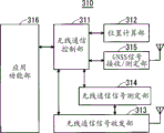
Figure 16 is the block diagram that represents the structure of the UE in first embodiment of the invention.
Figure 17 is the block diagram that represents the structure of the eNB_uu/s1 320 in first embodiment of the invention.
Figure 18 is the block diagram that represents the structure of the eNB 330 in first embodiment of the invention.
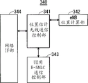
Figure 19 is the block diagram that represents the structure of the eNB E-SMLC 340 in first embodiment of the invention.
Figure 20 is the block diagram that represents the structure of the UE E-SMLC 350 in first embodiment of the invention.
Figure 21 is the block diagram that represents the structure of the wireless communication system 500 in second embodiment of the invention.
Figure 22 is the block diagram that represents the structure of the mobile network system 600 in third embodiment of the invention.
Figure 23 is the figure that represents to process to the UE transmission of the positional information between GMLC subordinate's Radio Access Network an example of relevant order.
Figure 24 is the figure that represents to process from the different UE transmission of the positional information between GMLC subordinate's Radio Access Network an example of relevant order.
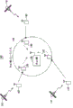
Figure 25 is the H(e representing in wireless communication system 140) figure of the position relationship of NB and UE.
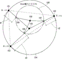
Figure 26 is the figure of the method for location estimation is described.
Figure 27 is the figure of the method for estimation for the mobile route after mensuration is described.
Embodiment
< prerequisite technology >
Before wireless communication system of the present invention is described, the wireless communication system of prerequisite technology is described.Wireless communication system is for example mobile communication system.
Be called as the W-CDMA(Wideband Code Division Multiple Access in the communication mode of the third generation: Wideband Code Division Multiple Access (WCDMA)) mode since calendar year 2001 in Japan commercial service.W-CDMA mode is the 3GPP(3rd Generation Partnership Project by the standardization body as mobile communication system: third generation partner program) communication mode formulated, and concluded the standard of version 10 editions.
In addition, in 3GPP, as the communication mode different from W-CDMA, study about being called as Long Term Evolution (Long Term Evolution:LTE) between radio zone, be called as the new communication mode of System Architecture Evolution (System Architecture Evolution:SAE) about the entire system structure that has comprised core network (being also only called network).This communication mode is also referred to as the 3rd .9 generation (3.9 Generation:3.9G) system.
Fig. 1 is integrally-built block diagram (with reference to 3GPP TS36. 300 v10.3.0(2010-03) (hereinafter referred to as " non-patent literature 6 ") the 4.6.1 chapter that represents the mobile communication system of LTE mode).Mobile communication system possesses: mobile terminal apparatus (being sometimes referred to as below " mobile terminal " or " subscriber equipment (User Equipment:UE) ") 71, have device (hereinafter referred to as " base station apparatus ") 72, MME/S-GW portion 73 and the HeNBGW(Home-eNB GateWay of base station functions: the eNB of family gateway) 74.Base station apparatus (being sometimes referred to as below " base station ") 72 and HeNBGW 74 form evolved universal terrestrial radio access network (Evolved Universal Terrestrial radio Access Network:E-UTRAN).In the mobile communication system of LTE mode, base station is called as E-UTRAN NodeB, eNodeB or eNB.
Mobile terminal (UE) 71 can carry out radio communication with base station 72, and carries out the transmitting-receiving of signal by radio communication.As base station (E-UTRAN NodeB, eNodeB, eNB) 72, there is the eNB 72-1 of macrocell and as eNB 72-2 of family of local node etc.About eNB 72-1, be coverage as the scope that can communicate with mobile terminal (UE) 71, there is larger extensive coverage.About the eNB 72-2 of family, as coverage, there is less small-scale coverage.
MME/S-GW portion 73 comprises mobile management entity (Mobility Management Entity; MME) and gateway (Serving Gateway be called for short:; Be called for short: any one party S-GW) or two sides.Below sometimes MME/S-GW portion 73 is called " MME portion ".
ENB 72-1 is connected with MME portion 73 by S1 interface, between eNB 72-1 and MME portion 73, control information is communicated.Also can connect multiple MME portion 73 to an eNB 72-1.Between eNB 72-1, connect by X2 interface, between eNB 72-1, control information is communicated.
The eNB 72-2 of family is connected with MME portion 73 by S1 interface, between the eNB 72-2 of family and MME portion 73, control information is communicated.A MME portion 73 is connected to multiple eNB 72-2 of family.Or the eNB 72-2 of family is connected with MME portion 73 via HeNBGW 74.
The eNB 72-2 of family is connected by S1 interface with HeNBGW 74.HeNBGW 74 is connected by S1 interface with MME portion 73.One or more eNB 72-2 of family are connected with a HeNBGW 74, by S1 interface, information are communicated.HeNBGW 74 is connected with one or more MME portion 73, by S1 interface, information is communicated.MME portion 73 and HeNBGW 74 are host node devices, and control being connected as the eNB 72-1 of base station and the eNB 72-2 of family and mobile terminal (UE) 71.
In addition, in 3GPP, studied below such structure.Support the X2 interface between the eNB 72-2 of family.That is, between the eNB 72-2 of family, connect by X2 interface, between the eNB 72-2 of family, control information is communicated.From MME portion 73, regard HeNBGW 74 as family eNB 72-2.From the eNB 72-2 of family, regard HeNBGW 74 as MME portion 73.
The situation and the eNB 72-2 of family that are connected to MME portion 73 at the eNB 72-2 of family via HeNBGW 74 are directly connected under all situations of situation of MME portion 73, and the interface between the eNB 72-2 of family and MME portion 73 is all S1 interface.HeNBGW 74 do not support to cross over multiple MME portion 73 such to the mobility of the eNB 72-2 of family or from the mobility of the eNB 72-2 of family.The eNB 72-2 of family forms and supports unique community.
In the mobile communication system of LTE mode, E-UTRAN supports relaying (relaying) (with reference to non-patent literature 6 4.7 chapters) by having relay station (being sometimes referred to as below via node (Relay Node:RN)).Via node is supported wireless protocols, S1 interface, the such base station functions of X2 interface of termination E-UTRA wave point.Via node is in order to be wirelessly connected to DeNB(Donor eNB), except base station functions, also support a part for mobile terminal function.A part for mobile terminal function is for example physical layer (physical layer), layer 2(layer-2), RRC, also have NAS function etc.At this, comprise relay station, be called " base station apparatus " or " base station "., term " base station apparatus " and " base station " comprise relay station.
About base station, for example a base station forms Yi Ge community.In this case, community is equivalent to base station.Be not limited to this, a base station also can form multiple communities.In this case, community is one by one equivalent to base station.
In 3GPP, about the channel architecture in the mobile communication system of LTE mode, determine following item (with reference to non-patent literature 6(5 chapter)).Physical channel (Physical channel) is described with Fig. 2.Fig. 2 is the figure that represents the physical channel using in the mobile communication system of LTE mode.
As shown in Figure 2, Physical Broadcast Channel (Physical Broadcast Channel:PBCH) the 401st, from base station 72 to the descending transmission channel of mobile terminal 71.BCH transmission block (transport block) is mapped to 4 subframes in 40ms interval.There is no the obvious signaling of 40ms timing.
Physical control channel format indicator channel (Physical Control Format Indicator Channel:PCFICH) the 402nd, from base station 72 to the descending transmission channel of mobile terminal 71.PCFICH will be for PDCCH(Physical Downlink Control Channel, physical downlink control channel) and the number of the OFDM symbol that uses is notified mobile terminal 71 from base station 72.Send PCFICH by each subframe.
Physical Downlink Control Channel (Physical Downlink Control Channel:PDCCH) the 403rd, from base station 72 to the descending transmission channel of mobile terminal 71.PDCCH notice is distributed (allocation) information, is distributed (allocation) information, the HARQ(Hybrid Automatic Repeat Request relevant to DL-SCH as the resource of a kind of paging channel (Paging Channel:PCH) of the transmission channel shown in Fig. 3 as the resource of a kind of DSCH Downlink Shared Channel (Downlink Shared Channel:DL-SCH) of the transmission channel shown in Fig. 3 described later: mixed automatic retransfer request) information.PDCCH transports uplink scheduling authorization (Uplink Scheduling Grant).PDCCH transports the Ack(Acknowledgement as the response signal to up transmission (response signal): affirmative acknowledgement) or Nack(Negative Acknowledgement: negative response) (being sometimes referred to as below " Ack/Nack ").PDCCH is also referred to as L1/L2 control signal.
Physical Downlink Shared Channel (Physical Downlink Shared Channel:PDSCH) the 404th, from base station 72 to the descending transmission channel of mobile terminal 71.In PDSCH, be mapped with DSCH Downlink Shared Channel (DL-SCH) as transmission channel and at least one party of PCH.
Physical Multicast Channel (Physical Multicast Channel:PMCH) the 405th, from base station 72 to the descending transmission channel of mobile terminal 71.In PMCH, be mapped with the Multicast Channel (Multicast Channel:MCH) as transmission channel.
Physical Uplink Control Channel (Physical Uplink Control Channel:PUCCH) the 406th, the up transmission channel from mobile terminal 71 to base station 72.PUCCH transports the Ack/Nack as the response signal to descending transmission (response signal).PUCCH transports CQI (Channel Quality Indicator:CQI) report.CQI is the quality information that represents the quality of received data or the quality of communication path.In addition, PUCCH transports dispatch request (Scheduling Request:SR).
Physical Uplink Shared Channel (Physical Uplink Shared Channel:PUSCH) the 407th, the up transmission channel from mobile terminal 71 to base station 72.In PUSCH, be mapped with a kind of Uplink Shared Channel (Uplink Shared Channel:UL-SCH) as the transmission channel shown in Fig. 3.
Physics HARQ indicator channel (Physical Hybrid ARQ Indicator Channel:PHICH) the 408th, from base station 72 to the descending transmission channel of mobile terminal 71.PHICH transports the Ack/Nack as the response signal to up transmission.Physical Random Access Channel (Physical Random Access Channel:PRACH) the 409th, the up transmission channel from mobile terminal 71 to base station 72.PRACH transports random access guiding (random access preamble).
Downlink reference signal (Reference signal) is as mobile communication system and known symbol.Following 5 kinds of downlink reference signals are defined.Cell special reference (Cell-specific reference signal:CRS), MBSFN reference signal (MBSFN reference signal), as the reference signal for data demodulates (Demodulation Reference Signal:DM-RS) of UE DRS (Dedicated Reference Signal) (UE-specific reference signal), location reference signals (Positioning reference signal:PRS), channel information reference signal (Channel-State Information reference signal:CSI-RS).As the mensuration of the physical layer of mobile terminal, exist the received power (Reference Signal Received Power:RSRP) of reference signal to measure.
Transmission channel (Transport channel) is described with Fig. 3.Fig. 3 is the figure that represents the transmission channel using in the mobile communication system of LTE mode.In Fig. 3 (A), the mapping between descending transmission channel and down physical channel is shown.In Fig. 3 (B), the mapping between uplink transport channel and uplink physical channel is shown.
In the descending transmission channel shown in Fig. 3 (A), broadcast channel (Broadcast Channel:BCH) is broadcast to the overall coverage of its base station (community).BCH is mapped to Physical Broadcast Channel (PBCH).
In DSCH Downlink Shared Channel (Downlink Shared Channel:DL-SCH), applied and utilized HARQ(Hybrid ARQ: hybrid ARQ) Retransmission control.DL-SCH can realize the broadcast of the overall coverage of (community) to base station.DL-SCH supports the resource of dynamic or semi-static (Semi-static) to distribute.Semi-static resource is distributed also referred to as continuous dispatching (Persistent Scheduling).DL-SCH supports the discontinuous reception (Discontinuous reception:DRX) of mobile terminal for the low power consumption of mobile terminal.DL-SCH is mapped to Physical Downlink Shared Channel (PDSCH).
Paging channel (Paging Channel:PCH) is supported the DRX of mobile terminal in order to realize the low-power consumption of mobile terminal.The broadcast of PCH request overall coverage of (community) to base station.PCH is mapped to the such physical resource of Physical Downlink Shared Channel (PDSCH) that can dynamically utilize in business.
Multicast Channel (Multicast Channel:MCH) is used to the broadcast of the overall coverage of (community) to base station.MCH supports that the SFN of the MBMS service (MTCH and MCCH) in the transmission of many communities is synthetic.MCH supports semi-static resource to distribute.MCH is mapped to PMCH.
In the uplink transport channel shown in Fig. 3 (B), in Uplink Shared Channel (Uplink Shared Channel:UL-SCH), applied and utilized HARQ(Hybrid ARQ: hybrid ARQ) Retransmission control.UL-SCH supports the resource of dynamic or semi-static (Semi-static) to distribute.UL-SCH is mapped to Physical Uplink Shared Channel (PUSCH).
Random Access Channel (Random Access Channel:RACH) is limited to control information.There is the risk of conflict in RACH.RACH is mapped to Physical Random Access Channel (PRACH).
Logic channel (Logical channel) is described to (with reference to non-patent literature 6(6 chapter) with Fig. 4).Fig. 4 is the key diagram that the logic channel using in the mobile communication system of LTE mode is described.In Fig. 4 (A), the mapping between descending logic channel and descending transmission channel is shown.In Fig. 4 (B), the mapping between up logic channel and uplink transport channel is shown.
Broadcast Control Channel (Broadcast Control Channel:BCCH) is the down channel for broadcast system control information.Be mapped to broadcast channel (BCH) or the DSCH Downlink Shared Channel (DL-SCH) as transmission channel as the BCCH of logic channel.
Paging Control Channel (Paging Control Channel:PCCH) is the down channel of the change for sending paging information (Paging Information) and system information (System Information).PCCH is used to network and does not know the situation of the subdistrict position of mobile terminal.Be mapped to the paging channel (PCH) as transmission channel as the PCCH of logic channel.
Common Control Channel (Common Control Channel:CCCH) is for the channel sending control information between mobile terminal and base station.CCCH be used to mobile terminal and network between do not there is RRC(Radio Resource Control: radio resource control) be connected the situation of (connection).On down direction, CCCH is mapped to the DSCH Downlink Shared Channel (DL-SCH) as transmission channel.On up direction, CCCH is mapped to the Uplink Shared Channel (UL-SCH) as transmission channel.
Multicast control channel (Multicast Control Channel:MCCH) is for 1 pair of multiple down channel sending.MCCH is used to the transmission of one or several MTCH MBMS control information from network to mobile terminal.Mobile terminal during MCCH is only received by MBMS uses.MCCH is mapped to the Multicast Channel (MCH) as transmission channel.
Dedicated Control Channel (Dedicated Control Channel:DCCH) is the channel that 1 pair of 1 ground sends the dedicated control information between mobile terminal and network.It is that RRC connects the situation of (connection) that DCCH is used to mobile terminal.DCCH is mapped to Uplink Shared Channel (UL-SCH) in up, is mapped to DSCH Downlink Shared Channel (DL-SCH) in descending.
Dedicated Traffic Channel (Dedicated Traffic Channel:DTCH) is the channel that user profile sends 1 communication of 1 couple to Specialised mobile terminal of use.DTCH exists in up and descending.DTCH is mapped to Uplink Shared Channel (UL-SCH) in up, is mapped to DSCH Downlink Shared Channel (DL-SCH) in descending.
Multicast service channel (Multicast Traffic Channel:MTCH) is the down channel that the business datum from network to mobile terminal sends use.MTCH is the channel that mobile terminal used in only being received by MBMS.MTCH is mapped to Multicast Channel (MCH).
In mobile communication system, in order to improve wireless access performance, sometimes use femto cell base station (for example, H(e) NB) or mobile wireless relay station (for example, Mobile Relay(e) NB, Mobile Relay Node) etc. mobile base station apparatus.At this, " H(e) NB " the expression eNB of family and the NB of family.In addition, " (e) NB " represents eNB and NB.
As the location estimation method of such base station apparatus, although there is disclosed method in aforesaid non-patent literature 5 and patent documentation 1 ~ 3, even but use these methods, be also difficult to estimate the position of base station apparatus in the situation that there is mobile base station apparatus.In addition, due to the situs ambiguus of base station apparatus, so be also difficult to estimate the position of mobile terminal apparatus.
Thereby, seek can easily estimate the position of base station apparatus and utilize this estimated result can easily estimate the wireless communication system of the position of mobile terminal apparatus in the mobile situation of base station apparatus.So, adopted in the present invention the structure of following execution mode.
< the first execution mode >
In the present embodiment, describe for the situation that applies the present invention to belong to the mobile base station of E-UTRAN and possess its wireless communication system.
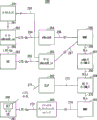
Fig. 5 is the block diagram that represents the structure of mobile network system 200.Mobile network system 200 shown in Fig. 5 has the location estimation function of disclosed UE in Fig. 6 .1-1 of non-patent literature 1.Below sometimes " location estimation " is called " location (positioning) ", and the location estimation of UE is called to " UE locates (UE positioning) ".
Location estimation (positioning) refers to, measures some signal relevant to position and carrys out geographic position and the translational speed (with reference to non-patent literature 3 4.2 chapters and non-patent literature 2 4.2 chapters) of estimated position estimation object according to the information of this mensuration.
Mobile network system 200 is constituted as to be possessed: UE 201, GERAN(Global System for Mobile Communications(GSM(registered trade mark)) and Enhanced Digital rates for GSM Evolution(EDGE) Radio Access Network: global system for mobile communications and enhanced data rates for gsm evolution radio access network) 202, UTRAN(Universal Terrestrial Radio Access Network: universal terrestrial radio access network) 203, E-UTRAN 204,2G-MSC(Second Generation-Mobile services Switching Centre: the second generation-mobile services switching centre) 205,2G-SGSN(Second Generation-Serving General Packet Radio Service(GPRS) Support Node: the second generation-serving general packet radio service support node) 206,3G(Third Generation: the third generation) SGSN 207, MSC server (server) 208, MME 209, E-SMLC(Evolved Serving Mobile Location Centre: evolved Serving Mobile Location Center) 210, SLP(Secure User Plane Location(SUPL) Location Platform: secure user plane position location platform) 211, GMLC(Gateway Mobile Location Centre(MLC): Gateway Mobile Location Center) 212, LRF(Location Retrieval Function: location retrieval function) 213, PPR(Privacy Profile Register: privacy profile register) 214, E-CSCF(Emergency Call Service Control Function(CSCF): emergency call service control function) 215, gsmSCF 216, OSA-LCS(Open Service Access-Location Service: open service access-positioning service) 217, outside LCS client (External LCS Client) 218, home subscriber server (Home Subscriber Server:HSS) 219, PMD(Pseudonym mediation device functionality: pseudo-name arbitration equipment function) 220, and LIMS-IWF(Location IP Multimedia Subsystem-Interworking Function: position IP Multimedia System-interworking function) 221.
In the device of formation mobile network system 200, device except mobile terminal apparatus (UE 201 etc.) and base station apparatus (eNB in E-UTRAN204 etc.), such as 2G- MSC 205,2G- SGSN 206,3G-SGSN 207, MSC server 208, MME 209, E-SMLC 210, SLP 211, GMLC 212, LRF 213, PPR 214, E-CSCF 215, gsmSCF 216, OSA-LCS 217, outside LCS client 218, HSS 219, PMD 220 and LIMS-IWF 221 etc. are equivalent to management devices.
2G-MSC 205 and MSC server (server) 208 carry out the authentication processing of the control of circuit-switched call and management, UE 201 and the management of the request relevant to the location estimation of UE 201.
2G- SGSN 206 and 3G-SGSN 207 carry out the authentication processing of the control of packet switched call and management, UE 201 and the management of the request relevant to the location estimation of UE 201.
Location estimation control and the computing etc. of UE 201 in the service area that E-SMLC 210 carries out in E-UTRAN 204.
OSA-LCS 217 is the OSA for utilizing the network function that location information service uses.OSA-LCS 217 is to provide open API(Application Programming Interface: API) function group (for example, with reference to 3GPP TS22. 127, TS23. 198, TS29. 198).
Outside LCS client 218 is the clients that can ask the position finding of the outside UE 201 of mobile network system 200.
LIMS-IWF 221 is at the IMS(IP Multimedia Subsystem:IP IP multimedia subsystem, IMS take in positioning service) framework in basic system, there is the function that interconnects use with other networks.For example, LIMS-IWF 221 has the function of exchange of the public user identity (Public User Identity) of the IMS that carries out certain subscriber etc.
Fig. 6 is the block diagram that represents the structure of the wireless communication system 260 of the prior art in E-UTRAN.The wireless communication system 260 of the prior art in the E-UTRAN shown in Fig. 6 is disclosed in Fig. 5-1 of non-patent literature 2.
In addition, between the SET 266 in object UE 261 and SLP 262, establishing logic is connected.This is called to SUPL(Secure User Plane Location: secure user plane location) carrying (bearer) 271.In addition, SLP 262 can be connected by special purpose interface 273 with E-SMLC 264 with UE.
ENodeB(E-UTRAN NodeB) 263 in E-UTRAN, be the base station apparatus of termination wireless communication protocol.
SUPL(Secure User Plane Location: secure user plane location) carrying (bearer) 271, SLP 262 and SET 266 have the Alliance by OMA(Open Mobile: Open Mobile Alliance) entity (with reference to OMA-AD-SUPL v2.0) of function in the SUPL of regulation.
SUPL carrying 271 is the user's carryings in SUPL.SLP 262 carries out the management of SUPL service and the entity of determining positions.SET 266 is the termination function with SUPL communication function.
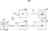
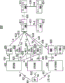
Fig. 7 is the block diagram that represents the structure of the wireless communication system 280 in first embodiment of the invention.Wireless communication system 280 be constituted as possess the object UE 261 identical with the wireless communication system 260 shown in aforesaid Fig. 6, SLP 262, eNodeB 263, UE E-SMLC 264 and MME(be sometimes referred to as " MME " below) 265, Vehicular system (Vehicular System) 281, target eNode B _ uu 282, UE 283, eNodeB 284, target eNode B _ s1 285, the 2nd MME 286 and E-SMLC 287 for eNB.
Target eNode B _ Uu 282 is connected by LTE-Uu interface 292 with UE 283.Target eNode B _ Uu 282 is connected by LTE-Uu interface 294 with eNodeB 284.Target eNode B _ Uu282 also can be connected by LTE-Un interface with eNodeB 284.
The 2nd MME 286 is connected by SLs interface 298 with E-SMLC 287 with eNB.ENB is connected by SLLs interface 299 with UE E-SMLC 264 with E-SMLC 287.
In the wireless communication system 280 shown in Fig. 7, except be used to the UE E-SMLC 264 of location estimation of UE in the existing wireless communication system 260 shown in Fig. 6, be newly provided with E-SMLC 287 for eNB.
Target eNode B _ uu 282 is mobile eNodeB.Target eNode B _ uu 282 is the eNodeB that carry out wireless connections with network side by wireless connections interfaces such as LTE-Uu interface or LTE-Un interfaces.Target eNode B _ uu 282 is for example mobile relay device (Mobile Relay Node).
Target eNode B _ s1 285 is the eNodeB that carry out wired connection by wired connection interfaces such as S1 interfaces with network side.Target eNode B _ s1 285 is for example femto cell base station (HeNB).
Fig. 7 is the figure of presentation logic structure, is not the figure that represents physical structure.For example, in Fig. 7, although record independently eNB E-SMLC 287 and E-SMLC 264 for UE, this record does not represent that eNB E-SMLC 287 and UE E-SMLC 264 are independently to install physically.ENB both can be configured to different devices with E-SMLC 287 from UE E-SMLC 264, also can be configured to a device.
The function relevant to location estimation that each logical block shown in Fig. 7 has has been shown in table 1.In table 1, represent the logical block that each function is configured by mark "○".
[table 1]

In table 1, location estimation function (positioning function (Positioning function)) 301 comprises PRCF for UE, PCF for UE, PSMF for UE, PRRM for UE, PRCF for eNB, PCF, eNB PSMF and eNB PRRM for eNB.
In position assessment function 301, UE PRCF, UE PCF, UE is equivalent to 5 chapters of non-patent literature 1 and PRCF(Positioning Radio Co-ordination Function that 6 chapters are recorded with PSMF and UE PRRM: positioned radio electricity coordination function), PCF(Positioning Calculation Function: location Calculation function), PSMF(Positioning Signal Measurement Function: framing signal measurement function) and PRRM(Positioning Radio Resource Management: positioned radio radio resource management).
In position assessment function 301, PRCF for eNB, for eNB, PCF, eNB are with PSMF and eNB PRRM take the location estimation of eNB as object, and each function that its content is recorded with 5 chapters and 6 chapters of non-patent literature 1 is identical.
Location client function (Location client functions:LCF) 302 comprises UE LCF and eNB LCF.
System processing capacity (System handling functions) 303 comprises LSCF for UE, LSBF for UE, LSOF for UE, LSBcF for UE, LSCTF for UE, LIMS-IWF for UE, LCF for eNB, LSCF for eNB, LSBF for eNB, LSOF for eNB, LSBcF, eNB LSCTF and eNB LIMS-IWF for eNB.
UE LCF in location client function 302, and UE LSCF in system processing capacity 303, UE LSBF, UE LSOF, UE LSBcF, each function of UE use LSCTF and UE use LIMS-IWF and location estimation function 301 similarly, be equivalent to 5 chapters of non-patent literature 1 and the LCF(Location Client Function that 6 chapters are recorded: location client function), LSCF(Location System Control Function: position system control function), LSBF(Location System Billing Function: position system billing function), LSOF(Location System Operations Function: position system operating function), LSBcF(Location System Broadcast Function: position system broadcast capability), LSCTF(Location System Co-ordinate Transformation Function: position system is coordinated mapping function) and LIMS-IWF(Location IMS Interworking Function: position IMS interworking function).
LCF for eNB in system processing capacity 303, LSCF for eNB, LSBF for eNB, LSOF for eNB, for eNB LSBcF, eNB with LSCTF and eNB LIMS-IWF and location estimation function 301 similarly, take the location estimation of eNB as object, and each function that its content is recorded with 5 chapters and 6 chapters of non-patent literature 1 is identical.
As represented by mark "○" at table 1, at Vehicular system, UE, eNB_uu/s1 and eNB with disposing conduct in the location estimation function 301 eNB PCF for the PCF of eNB in E-SMLC.In Vehicular system, UE, eNB_uu/s1 and eNB, dispose conduct in the location estimation function 301 eNB PSMF for the PSMF of eNB.In eNB, dispose conduct in the location estimation function 301 eNB PRRM for the PRRM of eNB.At eNB with disposing conduct in the location estimation function 301 eNB PRCF for the PRCF of eNB in E-SMLC.
The eNB PSMF configuring in eNB_uu/s1 is signal (being sometimes referred to as below " GNSS signal ") for GNSS and the signal of other eNB, and is applied to as positioning mode (Positioning Method) and uses the situation of E_PM_1, E_PM_2, E_PM_3, E_PM_4 or E_PM_5.
The eNB configuring in UE is the function identical with the location estimation of UE with PCF and eNB PSMF, and is applied to using as positioning mode the situation of E_PM_4.
The eNB configuring in Vehicular system is relevant to the positional information of measuring or estimating in the moving structure such as Train Transportation Simulation System and auto-navigation system thing with PCF and eNB PSMF, and is applied to using as positioning mode the situation of E_PM_6.
The eNB configuring in eNB is applied to using as positioning mode the situation of E_PM_1, E_PM_2, E_PM_3 or E_PM_5 with PSMF.Be described in the back about positioning mode.
About the eNB LCF of the location client function 302 as for eNB, suppose to be configured in eNB_uu/s1, MME and eNB use E-SMLC.
Although the eNB LCF configuring in eNB_uu/s1 is in the time that eNB resets and in the eNB that can realize the change of setting position but substantially used with stationary state detects mobile situation etc., resets and again asks position finding to realize.
ENB is in situation in order to append mensuration at position-based estimated result etc. with the eNB LCF configuring in E-SMLC, and enforcing location is estimated request and realized.
About the logical block of realizing as the UE LCF of the location client function 302 for UE, the UE and MME of the logical block of recording, append eNB E-SMLC in the table 6.2a as non-patent literature 1.This is position estimation accuracy in order to improve eNB and realizing take the location estimation that starts UE as object.
Then, describe for positioning mode.6 kinds of positioning modes have been shown in table 2.
[table 2]

In location estimation, being divided into following 3 kinds manages: do not become location estimation object " fixing eNB ", as HeNB, become " although can realize the eNB that the change of setting position is used with stationary state substantially " of location estimation object and as mobile relay node (Mobile Relay Node; Mobile RN: mobile RN) like that " substantially move while used eNB ".Thus, location estimation becomes easy.
E_PM_1 shown in table 2 is network support GNSS method.E_PM_2 is downgoing line positioning mode.E_PM_3 is Extended Cell ID method.E_PM_4 is the method based on UE tracked information.E_PM_5 is the method based on mobile eNB tracked information.E_PM_6 is the method based on assisting vehicle information.
Specifically, the identical function of location estimation of the UE recording in E_PM_1, E_PM_2 and E_PM_3 right and wrong patent documentation 2.E_PM_1, E_PM_2 and E_PM_3 are mounted with and receive and measure GNSS signal the go forward side by side function of the calculating of the hand-manipulating of needle to its result of function and the reception of the calculating of the hand-manipulating of needle to its result and the down link signal of measuring other eNB of going forward side by side becoming the eNB_uu/s1 of location estimation object, similarly carry out location estimation with the work of UE.
E_PM_4 utilize UE in the service area of community of the eNB_uu/s1 in becoming location estimation object at present and location estimation history in the past, in service area, the information relevant to eNB_uu/s1 such as cell information and mensuration information is carried out the location estimation of eNB_uu/s1.E_PM_4 is effective in the case of not receiving the electric wave of GNSS and the electric wave of other eNB.In addition, E_PM_4 is effective in " although can realize the eNB that the change of setting position is used with stationary state substantially ".
E_PM_5 utilize for become E_PM_1, the E_PM_2 of eNB_uu/s1 of location estimation object and the location estimation result of E_PM_3 or at present and the information relevant to eNB_uu/s1 such as location estimation history and mensuration information for eNB_uu/s1 in the past carry out location estimation.The information relevant to eNB_uu/s1 location estimation to as if eNB_uu in the situation that, also can comprise cell information in service area.E_PM_5 is mainly effective for " substantially move while used eNB ".
E_PM_6 is applied in the eNB arranging in mobile structure.E_PM_6 uses in the moving structure such as Train Transportation Simulation System and auto-navigation system thing institute positional information and the velocity information measuring and estimate and carries out location estimation.
About the location estimation request (being sometimes referred to as request for location services (Location Service Request)) of eNB, owing to using location management and multiple UE information under mobile status to carry out enforcing location estimation, estimate request so there are these 3 kinds of following (1) ~ (3).
(1) estimate the location estimation request (request for location services) of current position by the mensuration information of 1 time
(2) the multiple information on service time are estimated the location estimation request (primary importance is upgraded the request of processing) of 1 position
(3) imagine the utilization in moving and carry out continuously the location estimation request (second place is upgraded processing asks) of the mensuration of described (1)
In the following description, sometimes " request for location services " is called " LS request ", " primary importance is upgraded the request of processing " is called to " a LUP request ", " second place is upgraded the request of processing " is called to " the 2nd LUP request ".
Substantially, a LUP request is with " although can realize the eNB that the change of setting position is used take stationary state substantially " as object, and the 2nd LUP asks take " substantially move while used eNB " as object.
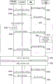
Below, describe for the work relevant to the location estimation of eNB.Fig. 8 is the figure that represents an example of the order of LS request.In this order, whole eNB positioning mode (eNB Positioning Method) of energy application of aforementioned.
Produced location estimation request in the eNodeB_uu/s1 that becomes LCF time, in step ST1, LS request is sent to MME by eNodeB_uu/s1.
At the eNB that becomes LCF, when having produced location estimation request in E-SMLC, in step ST2, LS request is sent to MME by eNodeB_uu/s1.
Produced location estimation request in the MME that becomes LCF time, in step ST3, LS request is identified as the internal event that should implement by MME.
The MME that receives LS request or be identified as internal event in step ST4 by this LS request notice to eNB E-SMLC.The processing of aforesaid step ST1 ~ step ST3 is independently, when be selected from these steps any one processing time, MME carries out the processing of step ST 4.
In step ST5, for eNB, E-SMLC, eNodeB and MME carry out eNodeB process.Specifically, receive the eNB E-SMLC asking from the LS of MME between the eNodeB and MME that become location estimation object, carry out as required giving and accepting of the determination data relevant to location estimation and auxiliary data.
Afterwards, in step ST6, eNodeB_uu/s1, eNodeB, MME and eNB carry out eNodeB_uu/s1 process with E-SMLC.Specifically, becoming between eNodeB_uu/s1, the eNodeB of location estimation object, MME, eNB E-SMLC, as eNodeB_uu/s1 process, carry out giving and accepting of the needed data of location estimation.
In step ST7, eNB carries out location estimation with E-SMLC.Having completed the reliability that the eNB E-SMLC of location estimation calculates by this estimated result and based on this estimated result is recorded in eNodeB admin table (being sometimes referred to as below " position table ") and upgrades position table.
In step ST8, eNB adds estimated positional information with E-SMLC, and the LS response that represents to finish dealing with is sent to MME.
Receive the MME responding from the LS of eNB E-SMLC LS response is sent to request source.
Specifically, in the situation that eNodeB_uu/s1 is request source,, in the case of having carried out the processing of aforesaid step ST1, MME sends to eNodeB_uu/s1 by LS response in step ST9.
In the situation that eNB E-SMLC is request source,, in the case of having carried out the processing of aforesaid step ST2, MME sends to eNB E-SMLC by LS response in step ST10.
In the situation that MME self is request source, in the case of having carried out the processing of aforesaid step ST3, MME in step ST11 by self confirming LS response.
In the case of the reliability of estimated result is low, also can again carry out enforcing location with other positioning mode or order and estimate, thus, seek the raising of precision.
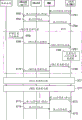
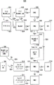
Fig. 9 is illustrated in the method based on UE tracked information that uses E_PM_4 as positioning mode, and used the figure of an example of the order in the situation of a LUP request.
First, with in E-SMLC, while having produced location estimation request due to origins of an incident such as the precision deficiencies of location estimation object eNodeB_uu/s1, transfer to step ST 21 at the eNB that becomes LCF.
In step ST 21, eNB carrys out the beginning of notifier processes to MME transmission primary importance renewal processing (LUP) request message with E-SMLC.
If the beginning (start) that a LUP request message can notifier processes, stop (stop) and positioning mode etc.
The MME that receives a LUP request message that represents the beginning of processing sends this request message, represents that a LUP request message of the beginning of processing carrys out the beginning of notifier processes eNodeB_uu/s1 in step ST 22.
The eNodeB_uu/s1 that receives a LUP request message that represents the beginning of processing confirms that in step ST 23 positioning mode is E_PM_4, and broadcast by system information etc., or to notify this community by dedicated channel to UE be the community (hereinafter referred to as " community of the method based on UE tracked information ") of locating with the method based on UE tracked information of E_PM_4.About this notice, both specific fields can be set as to system information, also can be by CSG(Closed Subscriber Group: closed subscriber group) etc. field substitute.In the situation that having used CSG field, in whole CSG community, always accept the information from UE.
Like this, by whether being the community of the method based on UE tracked information to UE notice, stop thereby can making unwanted information send in the community that is not the method based on UE tracked information.Thereby, can seek the minimizing of power consumption and the message volume of UE.
In step ST 24, a LUP response message is sent to MME by eNodeB_uu/s1.
The MME that receives a LUP response message sends to eNB E-SMLC by a LUP response message in step ST 25.Thus, start a LUP.
In the startup of a LUP, on opportunity arbitrarily, the startup of the eNB position updating process of the step ST 31 implementing between UE, eNodeB_uu/s1, eNodeB, MME and eNB are with E-SMLC becomes possibility.
The processing that the eNB position updating process of step ST 31 comprises following narrated step ST 26 ~ step ST 30.
At this, the work of UE is described.UE in service area in this community is receiving system information etc. first, and identify the community that this community is the method based on UE tracked information.The UE that identifies the community that is the method based on UE tracked information carries out the mensuration of the information relevant to the location estimation of current position as required, and immediately in step ST 26 by UE location information report by this device at present and the relevant information of the location estimation of measuring in the past send to MME.
By send like this UE location information report in step ST 26, thereby start the eNB position updating process being formed by the processing of effective step ST 26 ~ step ST 30 between UE, eNodeB_uu/s1, eNodeB, MME and eNB E-SMLC.
Have again, carrying out TAU(Tracking Area Update: tracking area update) in the situation that, also can send the information relevant to location estimation with the form being comprised in TAU formality.
In addition, this processing is by sending UE location information report by dedicated channel etc., thereby can not only be applied to the UE of RRC_Idle state, also can be applied to the UE of RRC_Connected state.
In addition,, in the time being accompany to the information relevant to location estimation the moment and send, can expect the raising of position estimation accuracy.By the setting of UE and the network equipment, thereby can also not send the information relevant to location estimation.
At this, RRC_Idle state is wait state, and RRC_Connected state is RRC connection status.In RRC_Idle state, carry out PLMN(Public Land Mobile Network: public land mobile network) select, the broadcast of system information (System Information:SI), paging (paging), cell reselection (cell re-selection), mobility etc.In RRC_Connected state, mobile terminal has RRC and connects (connection), and can carry out and the data transmit-receive of network, in addition, switches the measurement of (Handover:HO), abutting subdistrict (Neighbour cell) etc.
The MME that receives UE location information report in step ST 27 using the information receiving as MME and the UE location information report of eNB between E-SMLC send to eNB E-SMLC.
The eNB E-SMLC that receives UE location information report carries out location estimation by information and the location estimation result etc. of the UE positional information comprising in UE location information report and the UE that receives in the past in step ST 28.Complete the reliability that the eNB E-SMLC of location estimation calculates using this estimated result and based on this estimated result and be recorded in the position table of eNodeB admin table, and upgraded position table.
In step ST 29, with E-SMLC, positional information and the relative information after upgrading sends to MME as eNB location updating message to eNB.
The MME eNB location updating message using the information receiving as MME and between eNB_uu/s1 in step ST 30 that receives eNB location updating message sends to eNB_uu/s1.
In different multiple UE or same UE, repeat the processing of the eNB position updating process of step ST 31.
In the case of due to eNB with main causes such as having obtained enough precision in E-SMLC produced stop request, transfer to step ST 32.
In step ST 32, eNB sends and represents to process the LUP request message that stops and carry out notifier processes and stop MME with E-SMLC.
Receive and represent that the MME that processes the LUP request message stopping is in step ST 33, the LUP request message that eNodeB_uu/s1 transmission expression processing is stopped carrys out notifier processes to be stopped.
Receive the eNodeB_uu/s1 that represents to process the LUP request stopping and broadcasting by system information etc. in step ST 34, or be not the community of the method based on UE tracked information by dedicated channel to UE notice.
In step ST 35, a LUP response message is sent to MME by eNodeB_uu/s1.The MME that receives a LUP response message sends to eNB E-SMLC by a LUP response in step ST 36.
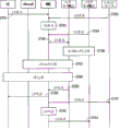
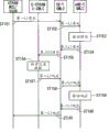
Figure 10 is illustrated in the method based on mobile eNB tracked information that uses E_PM_5 as positioning mode, and used the figure of an example of the order in the situation of the 2nd LUP request.
First, with in E-SMLC, when being arranged at the medium origins of an incident of moving structure thing such as train and having produced the location estimation request that uses this localization method and the 2nd LUP request due to location estimation object eNB, transfer to step ST 41 at the eNB that becomes LCF.
In step ST 41, with E-SMLC, to MME, transmission represents that the 2nd LUP request message of the beginning of processing carrys out notifier processes and starts to eNB.
If the beginning (start) that the 2nd LUP request message can notifier processes, stop (stop) and positioning mode etc.
Receive and represent to process the MME of the 2nd LUP request message starting and in step ST 42, location estimation object eNodeB_uu/s1 is sent this message, represents to process the 2nd LUP request message starting and carry out notifier processes and start.
Receive and represent that the eNodeB_uu/s1 that processes the 2nd LUP request message starting confirms that positioning mode is E_PM_5, and in step ST 43, the 2nd LUP response message is sent to MME.
The MME that receives the 2nd LUP response message in step ST 44 using the information receiving as MME and the two LUP response message of eNB between E-SMLC send to eNB E-SMLC.Thus, start the 2nd LUP.
In the startup of the 2nd LUP, on opportunity arbitrarily, the startup of the eNB position updating process of the step ST 51 implementing between eNodeB_uu/s1, eNodeB, MME and eNB are with E-SMLC becomes possibility.
The processing that the eNB position updating process of step ST 51 comprises following narrated step ST 45 ~ step ST 50.
In step ST 45, eNodeB_uu/s1 starts mensuration and the calculating of the information relevant to regular or irregular location estimation.
In step ST 46, eNodeB_uu/s1 comes regularly by eNB location information report or aperiodically the information relevant to this location estimation is sent to MME.Measured and calculated by eNodeB_uu/s1, the information relevant to location estimation that is sent to MME is for example and the E_PM_1 shown in table 2, E_PM_2 and the relevant information of E_PM_3.
The MME that receives eNB location information report in step ST 47 using the information receiving as MME and the eNB location information report of eNB between E-SMLC send to eNB E-SMLC.
The eNB E-SMLC that receives eNB location information report uses eNB positional information, the route map of moving structure thing and the setting position information of eNB etc. that in eNB location information report, comprise to carry out location estimation in step ST 48.Complete the reliability that the eNB E-SMLC of location estimation calculates using this estimated result and based on this estimated result and be recorded in the position table of eNodeB admin table, and upgraded position table.
In step ST 49, with E-SMLC, positional information and the relative information after upgrading sends to MME as eNB location updating message to eNB.
The MME eNB location updating message using the information receiving as MME and between eNB_uu/s1 in step ST 50 that receives eNB location updating message sends to eNB_uu/s1.
Repeat the processing of the eNB position updating process of step ST 51.
In the case of due to eNB with main causes such as having obtained enough precision in E-SMLC produced stop request, transfer to step ST 52.
In step ST 52, eNB represents to process to MME notice the 2nd LUP request message stopping with E-SMLC.
Receive the MME that represents to process the 2nd LUP request message that stops sends and represents to process the 2nd LUP request message stopping and carrying out notifier processes and stop eNodeB_uu/s1 in step ST 53.
Receive and represent that the eNodeB_uu/s1 that processes the 2nd LUP request message stopping sends to MME by the 2nd LUP response message in step ST 54.The MME that receives the 2nd LUP response message sends to eNB E-SMLC by the 2nd LUP response message in step ST 55.
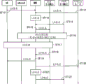
Figure 11 is illustrated in the method based on assisting vehicle information that uses E_PM_6 as positioning mode, and used the figure of an example of the order in the situation of the 2nd LUP request.
First, use in E-SMLC at the eNB that becomes LCF, when being arranged in the moving structure things such as train and can obtaining the origins of an incident such as the information relevant to location estimation produced the location estimation request that uses this positioning mode and the 2nd LUP request from the Vehicular system of this moving structure thing (Vehicular System) due to location estimation object eNB, transfer to step ST 61.
In step ST 61, with E-SMLC, to MME, transmission represents that the 2nd LUP request message of processing beginning carrys out notifier processes and starts to eNB.
Receive and represent that the MME that processes the 2nd LUP request message starting represents to process to location estimation object eNodeB_uu/s1 notice the 2nd LUP request message starting in step ST 62.
Receive and represent that the eNodeB_uu/s1 that processes the 2nd LUP request message starting confirms that positioning mode is E_PM_6, and in step ST 63, the 2nd LUP response message is sent to MME.
The MME that receives the 2nd LUP response message in step ST 64 using the information receiving as MME and the two LUP response message of eNB between E-SMLC send to eNB E-SMLC.Thus, start the 2nd LUP.
In the startup of the 2nd LUP, on opportunity arbitrarily, the startup of the eNB position updating process of the step ST 71 implementing between Vehicular system, eNodeB_uu/s1, eNodeB, MME and eNB are with E-SMLC becomes possibility.
The processing that the eNB position updating process of step ST 71 comprises following narrated step ST 65 ~ step ST 70.
In step ST 65, Vehicular system is reported the information relevant to location estimation as vehicle position information and is sent to termly or aperiodically eNodeB_uu/s1.The eNodeB_uu/s1 that receives vehicle position information report implements the information relevant computing relevant to location estimation from Vehicular system receiving termly or aperiodically.Then,, in step ST 66, eNodeB_uu/s1 sends to MME by the information relevant to this location estimation termly or aperiodically by eNB location information report.
The MME that receives eNB location information report in step ST 67 using the information receiving as MME and the eNB location information report of eNB between E-SMLC send to eNB E-SMLC., the eNB positional information receiving is forwarded to eNB E-SMLC by MME.
The eNB E-SMLC that receives eNB location information report uses eNB positional information, the route map of moving structure thing and the setting position information of eNB etc. that in eNB location information report, comprise to carry out location estimation in step ST 68.Complete the reliability that the eNB E-SMLC of location estimation calculates using this estimated result and based on this estimated result and be recorded in the position table of eNodeB admin table, and upgraded position table.
In step ST 69, eNB sends to MME with E-SMLC by eNB location updating message.
The MME eNB location updating message using the information receiving as MME and between eNB_uu/s1 in step ST 70 that receives eNB location updating message sends to eNB_uu/s1.
Repeat the processing of the eNB position updating process of step ST 71.Stop, request, transferring to step ST 72 with having produced due to main causes such as having obtained enough precision in location estimation in E-SMLC at eNB.
In step ST 72, eNB sends and represents to process the 2nd LUP request message that stops and carry out notifier processes and stop MME with E-SMLC.
Receive the MME that represents to process the 2nd LUP request message that stops sends and represents to process the 2nd LUP request message stopping and carrying out notifier processes and stop eNodeB_uu/s1 in step ST 73.
Receive and represent that the eNodeB_uu/s1 that processes the 2nd LUP request message stopping sends to MME by the 2nd LUP response message in step ST 74.The MME that receives the 2nd LUP response message in step ST 75 using the information receiving as MME and the two LUP response message of eNB between E-SMLC send to eNB E-SMLC.
Below, for the location estimation of the UE carrying out to the location estimation result with mobile eNB, relevant work describes.
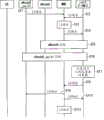
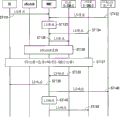
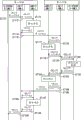
Figure 12 is the figure that is illustrated in an example of the order while carrying out the location estimation of UE by the location estimation result of mobile eNB.Figure 12 represents the formality of location estimation result that uses mobile eNB to be appended to non-patent literature 7(3GPP TS26. 305) Fig. 5 .1-1 in the figure of an example of order in disclosed order.Figure 13 is the figure that represents an example of the order of process between the E-SMLC of the step ST 86 shown in Figure 12.
Produced location estimation request in the UE that becomes LCF time, in step ST 81, LS request is sent to MME by UE.
Produced location estimation request in the outside LCS client that becomes LCF time, in step ST 82, LS request is sent to MME by outside LCS client.
Produced location estimation request in the MME that becomes LCF time, in step ST 83, LS request is identified as the internal event that should implement by MME.
At the eNB that becomes LCF, when having produced location estimation request in E-SMLC, in step ST 84, eNB sends to MME with E-SMLC by LS request.
The MME that receives LS request or be identified as internal event in step ST 85 by this LS request notice to UE E-SMLC.The processing of aforesaid step ST 81 ~ step ST 84 is independently, when be selected from these steps any one processing time, MME carries out the processing of step ST 85.
The UE that receives LS request message with E-SMLC in the LS of location estimation object request, by determining whether needs " the location estimation result of mobile eNB " whether comprising the information such as mobile eNB in service in-zone cell or abutting subdistrict.Need " the location estimation result of mobile eNB " in the case of being judged as, in step ST 86, UE carries out process between E-SMLC (Inter E-SMLC Procedures) with E-SMLC and eNB E-SMLC.Specifically, UE carries out the inquiry of the positional information of object eNB with E-SMLC to eNB E-SMLC.
Between E-SMLC, in process, in the step ST 101 shown in Figure 13, UE sends to eNB E-SMLC with E-SMLC by the request of eNB location information service.
In step ST 102, eNB carries out the mensuration of the retrieval of position data or the information relevant to the location estimation of eNB that becomes object with E-SMLC.
In step ST 103, eNB sends to UE E-SMLC with E-SMLC by the response of eNB location information service.
Afterwards, turn back to the order shown in Figure 12, in step ST 87, eNodeB, MME and UE carry out eNodeB process with E-SMLC.In eNodeB process, with between E-SMLC, carry out as required giving and accepting of the determination data relevant to location estimation and auxiliary data at eNodeB, MME, UE.
Afterwards, in step ST 88, UE, eNodeB, MME and UE carry out UE process with E-SMLC.In UE process, between UE, eNodeB, MME, UE are with E-SMLC, become the UE of object and giving and accepting of the needed data of location estimation.Then, carry out location estimation by UE with E-SMLC.
The UE that has completed location estimation with E-SMLC in step ST 89, estimated positional information is added to this estimated result as required and the reliability that calculates based on this estimated result in, LS response is sent to MME.
LS response is sent to request source by the MME that receives LS response.Specifically, in the situation that UE is request source,, in the case of having carried out the processing of aforesaid step ST 81, MME sends to UE by LS response in step ST 90.
In the situation that outside LCS client is request source,, in the case of having carried out the processing of aforesaid step ST 82, MME sends to outside LCS client by LS response in step ST 91.
In the situation that MME self is request source, in the case of having carried out the processing of aforesaid step ST 83, MME in step ST 92 by self confirming LS response.
In the situation that eNB E-SMLC is request source,, in the case of having carried out the processing of aforesaid step ST 84, MME sends to eNB E-SMLC by LS response in step ST 93.
Figure 14 and Figure 15 are the action opportunity that is illustrated in process between the E-SMLC figure with respect to an example of the order in the different situation of Figure 12.Figure 14 illustrates the order in the situation that of enforcement together in eNodeB process, figure 15 illustrates the order in the situation that of enforcement together in UE process.This is the order of using need " the location estimation result of mobile eNB " in each formality time.
Due to step ST 111 ~ step ST 115 of Figure 14 and each processing of each processing of step ST 117 ~ step ST 122 and step ST 81 ~ step ST 85 of Figure 12 and step ST 88 ~ step ST 93 identical, so omit common explanation.
In the order shown in Figure 14, in step ST 116, eNodeB, MME, UE carry out eNodeB process with E-SMLC and eNB E-SMLC.
Because each processing of step ST 131 ~ step ST 135, the step ST 136 shown in Figure 15 and step ST 138 ~ step ST 142 is identical with each processing of ST 81 ~ step ST 85, the step ST 87 shown in Figure 12 and step ST 89 ~ step ST 93, so omit common explanation.
In Figure 15, in step ST 137, UE, eNodeB, MME, UE carry out UE process with E-SMLC and eNB E-SMLC.
By doing like that above, thereby the location estimation of mobile eNB becomes possibility.In addition, location estimation by the estimated result of the position of this mobile base station for UE, thus, location estimation for the UE in the UE in the service area in mobile base station and near the service area mobile base station becomes possibility, and makes to become possibility as the expansion in location estimation region and the raising of precision of the UE of network entirety.
Figure 16 is the block diagram that represents the structure of the UE in first embodiment of the invention.UE 310 is constituted as to be possessed: radio communication control part 311, position calculation portion 312, wireless communication signals receiving and transmitting part 313, wireless communication signals determination part 314, GNSS signal reception/determination part 315 and application function portion 316.
Radio communication control part 311 carries out communication protocol control and the device management that radio communication is used.Radio communication control part 311 has PRRM function.Position calculation portion 312 has PCF, and carries out the calculating relevant to the location estimation of UE and eNB.
Wireless communication signals receiving and transmitting part 313 carries out modulation and demodulation, chnnel coding and the frequency translation etc. for transmitting/receiving wireless signal of communication.Wireless communication signals determination part 314 has the PSMF for wireless communication signals.
The PSMF that GNSS signal reception/determination part 315 has for GNSS signal.Application function portion 316 carries out user interface and application is processed.
Figure 17 is the block diagram that represents the structure of the eNB_uu/s1 320 in first embodiment of the invention.ENB_uu/s1 320 is constituted as to be possessed: radio communication control part 321, position calculation portion 322, wireless communication signals receiving and transmitting part 323, wireless communication signals determination part 324, GNSS signal reception/determination part 325, Vehicular system IF portion 326 and network IF portion 327.
Radio communication control part 321 carries out communication protocol control and the device management that radio communication is used.Radio communication control part 321 has PRRM function.Position calculation portion 322 has PCF, and carries out the calculating relevant to the location estimation of UE and eNB.
Wireless communication signals receiving and transmitting part 323 carries out modulation and demodulation, chnnel coding and the frequency translation etc. for transmitting/receiving wireless signal of communication.Wireless communication signals determination part 324 has the PSMF for wireless communication signals.
The PSMF that GNSS signal reception/determination part 325 has for GNSS signal.Vehicular system IF portion 326 has the interface function for communicating with Vehicular system.Network IF portion 327 has the interface function for communicating with Vehicular system IF portion 326, MME etc.
Figure 18 is the block diagram that represents the structure of the eNB 330 in first embodiment of the invention.ENB 330 is constituted as to be possessed: radio communication control part 331, position calculation portion 332, wireless communication signals receiving and transmitting part 333, wireless communication signals determination part 334 and network IF portion 335.
Radio communication control part 331 carries out communication protocol control and the device management that radio communication is used.Radio communication control part 331 has PRRM function.Position calculation portion 332 has PCF, and carries out the calculating relevant to the location estimation of UE and eNB.
Wireless communication signals receiving and transmitting part 333 carries out for the modulation of transmitting/receiving wireless signal of communication and demodulation, chnnel coding, frequency translation etc.Wireless communication signals determination part 334 has the PSMF for wireless communication signals.Network IF portion 335 has the interface function for communicating with MME etc.
Figure 19 is the block diagram that represents the structure of the eNB E-SMLC 340 in first embodiment of the invention.ENB is constituted as and possesses with E-SMLC 340: location estimation radio communication control part 341, eNB position calculation portion 342, E-SMLC communication control unit 343 and network IF portion 344 for UE.
Wireless communication protocol control function (PRCF) and device management function that the location estimation that location estimation radio communication control part 341 has eNB is used.ENB position calculation portion 342 has the PCF relevant to eNB.UE carries out using with UE the Control on Communication of E-SMLC with E-SMLC communication control unit 343.Network IF portion 344 has the interface function for communicating with MME etc.
Figure 20 is the block diagram that represents the structure of the UE E-SMLC 350 in first embodiment of the invention.UE is constituted as and possesses with E-SMLC 350: location estimation radio communication control part 351, UE position calculation portion 352, E-SMLC communication control unit 353 and network IF portion 354 for eNB.
Wireless communication protocol control function (PRCF) and device management function that the location estimation that location estimation radio communication control part 351 has UE is used.UE position calculation portion 352 has the PCF relevant to UE.ENB carries out using with eNB the Control on Communication of E-SMLC with E-SMLC communication control unit 353.Network IF portion 354 has the interface function for communicating with MME etc.
As described above in the present embodiment, eNB as management devices carries out for estimating mensuration and the calculating as the base station position information of the information relevant to the position of base station with E-SMLC, and plays a role with processing unit as the location estimation of estimating base station position information.Based on carrying out with the estimated relevant base station position information in the position to base station of E-SMLC the various processing of being undertaken by the management devices that comprises eNB E-SMLC by this eNB.
The processing of being undertaken by management devices is mobile terminal (UE) with the management of the mobile management of the control of radio communication control in the communicating by letter of base station, communication call, mobile terminal, wireless communication system and forms at least one the processing in the location information management of device of wireless communication system.The device that forms wireless communication system comprises mobile terminal and base station apparatus.
Like this in the present embodiment, be mounted with the function of location estimation processing unit in wireless communication system, described location estimation is carried out mensuration and the calculating for estimating base station position information with processing unit, and estimates base station position information.
Location estimation with processing unit by aforesaid mensuration and calculate and obtain " for carry out the various mensuration information of location estimation or this mensuration information is processed after information ", and estimate " information that the estimated position of the result of location estimation has been carried out in expression " used as base station position information.
Below these information are being called to " information relevant to the location estimation of base station "., the packets of information relevant to the location estimation of base station containing " for carry out the various mensuration information of location estimation or this mensuration information is processed after information " and " information of the estimated position of the result of location estimation has been carried out in expression " the two.The information relevant to the location estimation of base station be the wireless network of base station itself mensuration information, mobile terminal mensuration historical information and in service area the peripheral cell of cell history information, base station itself measure historical information, be mounted with that the moving structure thing of base station has estimate relevant information, such as estimate relevant information, train running information etc. with current position in auto-navigation system with current position.
Structure collects and manages the base station location estimating system of these information relevant to the location estimation of base station, makes as required it cooperate with the position estimating system of mobile terminal, estimates the information relevant to position such as position and translational speed of base station.In addition, by this estimated result being offered to the position estimating system of mobile terminal, thus the information relevant to position such as position and translational speed of estimation mobile terminal.
Like this, the position playing a role as base station location estimating system of wireless communication system is by historical information and estimate the position of base station from information relevant to the location estimation of base station such as the information at the position playing a role as other systems such as mobile terminal locations estimating systems.Thus, in the various situations such as situation and the situation that move often imagination base station that cannot obtain from outside for the information of estimated position, the estimation of the information that position and the translational speed etc. of base station is relevant to position becomes possibility.
For example, in the case of almost cannot be from outside obtains estimating for the base station position information of the base station the situation of the information of estimated position under static situation to base station as femto cell base station, as the information relevant to the location estimation of base station, use the historical information of mobile terminal.Substantially move continuously owing to can imagining mobile terminal, so be used as base station position information by the historical information that uses mobile terminal, the estimation of the position of base station becomes possibility.
In addition, in the case of estimating that imagination is as mobile wireless relay station often the base station position information of mobile base station, what use that the peripheral cell mensuration historical information of base station itself or moving structure thing have estimates relevant information to current position.Thus, adopt base station position information, the location estimation of base station becomes possibility.
In addition, in the present embodiment, base station is such as arranged on, as the moving structure thing of mobile structure, in the vehicle such as automobile or train, moves together with moving structure thing.Base station location estimation unit is obtained the moving structure object location information relevant to the position of moving structure thing from moving structure thing management system, for example auto-navigation system or the Train Management system of moving structure thing or management moving structure thing, and moving structure object location information based on obtained is estimated base station position information.Thus, can more easily estimate base station position information.
In addition, in the present embodiment, with E-SMLC, base station being divided into any one in following 3 kinds as the eNB of management devices manages: (a) be fixed the fixed base stations device, (b) that arrange and used with stationary state are configured to movable base station apparatus mobile and that used with stationary state and (c) are configured to mobile and move while the mobile base station device that used.Based on the classification of being undertaken by this management devices, estimate base station position information by base station location estimation unit.Thus, can prevent the execution of the unwanted processing as the fixed base stations device for being used with stationary state carries out location estimation process.Thereby, can carry out more efficiently the estimation processing of base station position information.
< the second execution mode >
Then, describe for the second execution mode of the present invention.In the present embodiment, describe for the situation that applies the present invention to the mobile NodeB that belongs to UTRAN.
Figure 21 is the block diagram that represents the structure of the wireless communication system 500 in second embodiment of the invention.
Target NodeB _ uu 501 is connected by V interface 521 with Vehicular system 502.Vehicular system 502 is connected by V interface 522 with target NodeB _ iub 503.Target NodeB _ uu 501 is connected by Uu interface 523 with NodeB 504.Target NodeB _ iub 503 is connected by Uu interface 524 with NodeB 504.
Target NodeB _ iub 503 is connected by Iub interface 525 with a RNC 505.NodeB 504 is connected by Iub interface 526 with the 2nd RNC 506.The one RNC 505 is connected by Iur interface 527 with the 2nd RNC 506.The 2nd RNC 506 is connected by Iu interface 528 with a CN 507.
The 2nd NodeB 511 is connected by Iub interface 532 with the 4th RNC 513.The 3rd RNC 512 is connected by Iur interface 533 with the 4th RNC 513.The 3rd RNC 512 is connected by Iu interface 534 with the 2nd CN 514.
The 3rd RNC 512 is connected by Iupc interface 535 with SAS 515 with UE.UE is connected by Iupc_LL interface 536 with NodeB SAS 516 with SAS 515.NodeB is connected by Iupc interface 537 with the 2nd RNC 506 with SAS 516.The 2nd RNC 506 is connected by Iur interface 538 with the 3rd RNC 512.
In the structure shown in Figure 21, will as the location estimation of existing UE with the self SMLC of SAS as UE SAS, and be newly provided with NB SAS and be used as eNodeB SAS.
NodeB is to carry out the location information management of the NodeB in UTRAN and the entity of calculating with SAS 516.In the situation that considering that SAS is comprised in RNC, in certain RNC, comprise and carry out the location information management of NodeB and the entity of calculating.
In addition,, as mobile NodeB, will as mobile relay device (Mobile Relay Node), be made as NodeB_uu with the interface (Uu interface particularly) of network side by the NodeB of wireless connections.In addition, Iub interface as femto cell base station (HNB) is made as to eNodeB_iub by the NodeB of wired connection.
In the case of the function of the information management of RNC enforcing location and calculating, communicate with Iur interface.
Structure shown in Figure 21 is logical construction, and representation case is not independently installed with SAS and UE SAS physically as NB.
The relevant function example of location estimation having to the each logical block shown in Figure 21 has been shown in table 3.
[table 3]
。
In table 3, with table 1 similarly, location estimation function 551 comprises PRCF for UE, PCF for UE, PSMF for UE, PRRM for UE, PRCF for NB, PCF, NB PSMF and NB PRRM for NB.
In position assessment function 551, PRCF for UE, for UE, PCF, UE are equivalent to 5 chapters of non-patent literature 1 and PRCF, PCF, PSMF and the PRRM that 6 chapters are recorded with PSMF and UE PRRM.
In position assessment function 551, PRCF for NB, for NB, PCF, NB are with PSMF and NB PRRM take the location estimation of NB as object, and the function that its content is recorded with 5 chapters and 6 chapters of non-patent literature 1 is identical.
Location client function 552 comprises UE LCF and eNB LCF.System processing capacity 553 comprises LSCF for UE, LSBF for UE, LSOF for UE, LSBcF for UE, LSCTF for UE, LIMS-IWF for UE, PRCF for NB, PCF for NB, PSMF for NB, PRRM for NB, LCF for NB, LSCF for NB, LSBF for NB, LSOF for NB, LSBcF, NB LSCTF and NB LIMS-IWF for NB.
LSCF for UE in LCF and system processing capacity 553 for UE in location client function 552, LSBF for UE, LSOF for UE, for UE, LSBcF, UE LSCTF and UE LIMS-IWF are equivalent to 5 chapters of non-patent literature 1 and LCF, LSCF, LSBF, LSOF, LSBcF, LSCTF and the LIMS-IWF that 6 chapters are recorded similarly.
In addition, PRCF for NB in processing capacity 553, PCF for NB, PSMF for NB, PRRM for NB, LCF for NB, LSCF for NB, LSBF for NB, LSOF for NB, for NB LSBcF, NB with LSCTF and NB LIMS-IWF and location estimation function 551 similarly, take the location estimation of NB as object, and the function that its content is recorded with 5 chapters and 6 chapters of non-patent literature 1 is identical.
As represented by mark "○" in table 3, be configured in NB, NB_uu/iub, UE, Vehicular system and RNC/SAS(UE positioning function for the PCF in the location estimation function 551 of NB and PSMF) in.In addition, the PRRM in location estimation function 551 and PRCF are configured in RNC/SAS(NB positioning function) in.
At this, the PSMF in NB_uu/s1 is the signal for GNSS signal and other NB, and is applied to using as positioning mode the situation of PM_1, PM_2_1, PM_2_2, PM_3, PM_4, PM_5.
PCF in UE and PSMF are the functions identical with the location estimation of UE, and are applied to using as positioning mode the situation of PM_4.
PCF in Vehicular system and PSMF are relevant to the positional information of measuring and estimating in the moving structure such as Train Transportation Simulation System and auto-navigation system thing, and are applied to using as positioning mode the situation of PM_6.
PSMF in NB is applied to using as positioning mode the situation of PM_1, PM_2_1, PM_2_2, PM_3, PM_5.Be described in the back about positioning mode.
About the location client function 552 for NB, be made as NB_uu/s1, RNC/SAS(NB positioning function).
Although the LCF in NB_uu/s1 is in the time that NB resets and in the NB that can realize the change of setting position but substantially used with stationary state detects mobile situation etc., resets and again asks position finding to realize.
RNC/SAS(NB positioning function) in LCF be that in the situation etc. of the mensuration in order to append at position-based estimated result, enforcing location is estimated request and realizes.
About the location client function 552 for UE, the table 6.2 of non-patent literature 1 is appended to RNC/SAS(NB positioning function).This is position estimation accuracy in order to improve NB and realizing take the location estimation that starts UE as object.
Then, describe for positioning mode.7 kinds of positioning modes have been shown in table 4.
[table 4]

Localization method is identical with aforesaid the first execution mode, and E_PM_1 is called to PM_1, E_PM_2 is called to PM_2_1 and PM_2_2, and E_PM_3 is called to PM_3, E_PM_4 is called to PM_4, E_PM_5 is called to PM_5, E_PM_6 is called to PM_6.
PM_1 is network support GNSS method.PM_2_1 measures to arrive time difference (Observed Time Difference Of Arrival; Be called for short: OTDOA) method.PM_2_2 is uplink time-difference of arrival (Uplink Time Difference Of Arrival; Be called for short: U-TDOA) method.PM_3 is community ID method.PM_4 is the method based on UE tracked information.PM_5 is the method based on mobile eNB tracked information.PM_6 is the method based on assisting vehicle information.
Specifically, the identical function of location estimation of the UE recording in PM_1, PM_2_1, PM_2_2 and PM_3 right and wrong patent documentation 3, and the function that is mounted with reception, measures and calculates function and reception, the mensuration of GNSS signal and calculate the down link signal of other NB becoming the NB_uu/iub of object, similarly carries out location estimation with the work of UE.
Below, eNB_uu/s1 is called to NB_uu/iub, eNB is called to NB, MME/UE E-SMLC is called to SAS for RNC/UE, MME/eNB E-SMLC is called to RNC/NB SAS, realized the function identical with aforesaid the first execution mode.Thus, the location estimation of mobile NB and used the location estimation of the UE of this estimated result to become possibility.
<
threeexecution mode >
Then, describe for the 3rd execution mode of the present invention.In the present embodiment, in the position finding formality of (e) of aforesaid first and second execution mode NB, particularly carry out as " the multiple information on service time are estimated a LUP request of 1 position ", " utilization during imagination is mobile; and carry out continuously the 2nd LUP request of the mensuration of a LUP request " in the situation of such estimation, as E-UTRAN and UTRAN, between different Radio Access Networks or between different GMLC subordinates' Radio Access Network, exchange information relevant to the location estimation of base station etc. and use this information.Thus, can expect the raising of position estimation accuracy.
Figure 22 is the block diagram that represents the structure of the mobile network system 600 in third embodiment of the invention.Below, sometimes eNB and NB are referred to as to " (e) NB ".
The one UE is connected by Lg interface 632 with 2G-MSC 605 with GMLC 611.The one UE is connected by Lg interface 633 with 2G-SGSN 606 with GMLC 611.The one UE is connected by Lg interface 634 with 3G-SGSN 607 with GMLC 611.The one UE is connected by Lg interface 635 with MSC server 608 with GMLC 611.The one UE is connected by SLg interface 636 with MME 609 with GMLC 611.
The one GMLC 611 and first for UE (e) NB is connected by LLg interface 637 with GMLC 612.The 2nd GMLC 613 and second for UE (e) NB is connected by LLg interface 638 with GMLC 614.The one UE is connected by Lr interface 639 with the 2nd UE GMLC 613 with GMLC 611.
UE is equivalent to GMLC the GMLC(Gateway Mobile Location Centre that the 6.3.3 chapter of non-patent literature 1 is recorded: Gateway Mobile Location Center).In the present embodiment, as shown in figure 22, to be connected to the mode of UE GMLC, (e) NB GMLC is set.
Should carry out the transmission processing of the positional information between UE GMLC subordinate's Radio Access Network and the transmission processing of other the UE positional information of GMLC subordinate's Radio Access Network with GMLC by (e) NB.
Figure 22 is the figure of presentation logic structure, is not the figure that represents physical structure.For example, in Figure 22, although independently recorded first and second (e) NB GMLC 612,614 and GMLC 611,613 for first and second UE, this record does not represent first and second (e) NB GMLC 612,614 and first and second UE GMLC the 611, the 613rd, independently installs physically.
Figure 23 is the figure that represents to process to the UE transmission of the positional information between GMLC subordinate's Radio Access Network an example of relevant order.Figure 23 illustrates the situation that the UTRAN pair of information relevant to location estimation in E-UTRAN is asked.
First, the MSC/SGSN of UTRAN has reported judging the positional information of the base station that needs other Radio Access Networks in service area internal information etc. of other Radio Access Networks in the case of the UE in the base station of other Radio Access Networks or the service area in this wireless access network system detected by the base station of this wireless access network system, in step ST 151, the MSC/SGSN of UTRAN sends primary importance information (Location Information to UE with GMLC; Be called for short: LI) request message.
The UE GMLC that receives a LI request message sends to a LI request message (e) NB GMLC in step ST 152.Receive (e) NB GMLC of a LI request in step ST 153, verify the request of authentication etc. of the device of such as message authentication and request source and the appropriate property of request source.
(e) NB, with GMLC in the case of no problem aspect the checking of appropriate property that is judged as request in step ST 153 and request source, in step ST 154, sends to UE GMLC by the 2nd LI request message.The UE GMLC that receives the 2nd LI request sends to the 2nd LI request message the E-SMLC of E-UTRAN in step ST 155.
The checking of the appropriate property of the request in step ST 153 and request source both can be implemented with GMLC by UE, also can share the checking of the checking of request and the appropriate property of request source.
The E-SMLC that receives the E-UTRAN of the 2nd LI request retrieves the position data of asking in step ST 156.In step ST 157, the 2nd LI response is sent to UE GMLC by the E-SMLC of E-UTRAN.
The UE GMLC that receives the 2nd LI response sends to eNB GMLC by the 2nd LI response in step ST 158.The eNB GMLC that receives the 2nd LI response verifies the appropriate property of the 2nd LI response and response source in step ST 159.
ENB in the case of no problem aspect the checking of appropriate property that is judged as response in step ST 159 and response source, in step ST 160, sends to UE GMLC by a LI response message with GMLC.The UE GMLC that receives a LI response message sends to a LI response MSC/SGSN of UTRAN in step ST 161.
In step ST 159, with step ST 153 in the same manner, both can implement by UE the checking of response and the appropriate property of response source with GMLC, the checking that also can share the checking of response and the appropriate property of response source.
Figure 24 is the figure that represents to process from the different UE transmission of the positional information between GMLC subordinate's Radio Access Network an example of relevant order.Figure 24 illustrates the situation that E-UTRAN pair of the first network information relevant to location estimation in the E-UTRAN of second network asked.
First, the UE of the E-UTRAN E-SMLC of first network in base station or the service area in this wireless access network system of other Radio Access Networks that other GMLC subordinates detected by the base station of this wireless access network system reports other GMLC subordinates' being judged as the positional information of the base station that needs other Radio Access Networks in service area internal information etc. of other Radio Access Networks, in step ST 171, the E-UTRAN E-SMLC of first network sends the one LI request message between GMLC to the UE of first network with GMLC.
The UE GMLC that receives the first network of the one LI request message between GMLC in step ST 172 by GMLC between a LI request message send to the eNB GMLC of first network.
The eNB GMLC that receives between GMLC the first network of the one LI request verifies that in step ST 173 the one LI between GMLC asks and the appropriate property of request source.The eNB of first network with GMLC in the case of no problem aspect the checking of appropriate property that is judged as between the GMLC in step ST 173 the one LI request and request source, in step ST 174, the one LI request message between GMLC is sent to the UE GMLC of first network.
The UE GMLC of first network that receives between GMLC the one LI request in step ST 175 by GMLC between the 2nd LI request message send to and ask the network of destination, the UE GMLC of second network specifically.
The checking of the appropriate property of the request in step ST173 and request source both can be implemented with GMLC by the UE of first network, also can share the checking of the checking of request and the appropriate property of request source.
The UE GMLC of second network that receives between GMLC the 2nd LI request in step ST 176 by GMLC between the 2nd LI request message send to the eNB GMLC of second network.
The eNB GMLC that receives the second network of the 2nd LI request between GMLC verifies the appropriate property of request and request source in step ST 177.The eNB of second network in the case of no problem aspect the checking of appropriate property that is judged as request in step ST 177 and request source, in step ST 178, sends to the 3rd LI request message between GMLC the UE GMLC of second network with GMLC.
The UE GMLC of second network that receives between GMLC the 3rd LI request in step ST 179 by GMLC between the 3rd LI request send to the E-UTRAN E-SMLC of the second network of asking destination.
The checking of the appropriate property of the request in step ST 177 and request source both can be implemented with GMLC by the UE of second network, also can share the checking of the checking of request and the appropriate property of request source.
Receive the E-UTRAN E-SMLC of second network of the 3rd LI request message between GMLC in step ST 180, the position data that retrieval is asked.In step ST 181, the E-UTRAN E-SMLC of second network sends to the 3rd LI response message between GMLC the UE GMLC of second network.
The UE GMLC of second network that receives between GMLC the 3rd LI response in step ST 182 by GMLC between the 3rd LI response message send to the eNB GMLC of second network.
The eNB GMLC that receives the second network of the 3rd LI response message between GMLC verifies the appropriate property of the 3rd LI response and response source between GMLC in step ST 183.The eNB of second network with GMLC in the case of no problem aspect the checking of appropriate property that is judged as between the GMLC in step ST 183 the 3rd LI response and response source, in step ST 184, the 2nd LI response message between GMLC is sent to the UE GMLC of second network.
The UE GMLC of second network that receives between GMLC the 2nd LI response in step ST 185 by GMLC between the 2nd LI response message send to the UE GMLC of the first network of request source.
In step ST 183, with step ST 177 similarly, both can implement by the UE of second network the checking of response and the appropriate property of response source with GMLC, the checking that also can share the checking of response and the appropriate property of response source.
Receive the UE GMLC of the first network of the 2nd LI response message between GMLC in step ST 186, the 2nd LI response message between GMLC is sent to the eNB GMLC of first network.
The eNB GMLC that receives between GMLC the first network of the 2nd LI response verifies that in step ST 187 the 2nd LI between GMLC responds and the appropriate property of response source.The eNB of first network with GMLC in the case of no problem aspect the checking of appropriate property that is judged as between the GMLC in step ST 187 the 2nd LI response and response source, in step ST 188, the one LI response message between GMLC is sent to the UE GMLC of first network.
The UE GMLC of first network that receives between GMLC the one LI response in step ST 189 by GMLC between a LI response message send to the E-UTRAN E-SMLC of the first network of request source.
In step ST 187, with step ST 173 similarly, both can implement by the UE of first network the checking of response and the appropriate property of response source with GMLC, the checking that also can share the checking of response and the appropriate property of response source.
By adopting above structure, thereby, use the location estimation of the information relevant from the location estimation of the base station of different Radio Access Networks or different GMLC subordinate's Radio Access Network to become possibility.Thus, can realize the raising of position estimation accuracy.
< the 4th execution mode >
Then, describe for the 4th execution mode of the present invention.In the present embodiment, describe for the location estimation of E_PM4's and PM_4's the method based on UE tracked information in the positioning mode in aforesaid first and second execution mode.As an example, be considered as (e) NB_s1 and have the situation of HeNB and 3 UE.
Figure 25 is the H(e representing in wireless communication system 140) figure of the position relationship of NB and UE.In Figure 25, suppose H(e) NB 148 and this H(e) cell area of the cell area supported of NB (be sometimes referred to as below " H(e) NB ") 149 electric waves that are arranged on GNSS cannot arrive and also have from other the electric wave of (e) NB place that is beyond one's reach.That is to say, be arranged on the PM_3 of (E_) PM_1 shown in table 2 and table 4 ~ (E_) and (E_) in environment that the positioning mode of PM5, (E_) PM_6 can not be tackled.
This HeNB asks to start the location estimation of the method based on UE tracked information by the LUP in aforesaid the first execution mode, in addition, broadcasting by system information is the community of the method based on UE tracked information.
By 3 UE the first ~ three UE 142 ~ 144 be made as originally not in service area, obtain the information relevant to location estimation at certain place place, thereafter in this H(e) in the service area of the cell area 149 of NB.That is to say, 3 UE 142 ~ 144 are made as and move to the position represented by each reference symbol 145 ~ 147.Have, these 3 UE 142 ~ 144 do not need in time simultaneously in service area again.
Now, each UE obtains system information, and the community that is the method based on UE tracked information, notified this community.Then, send over the obtained relevant information of the location estimation to nearest by UE location information report.The information that described to nearest location estimation is relevant can also be the information of multiple points.
Can be according to estimating position, specifically latitude and longitude in the past to 3 UE information that location estimation of the first ~ three UE 142 ~ 144 is relevant via HeNB.
Location estimation is now described with Figure 26.Figure 26 is the figure of the method for location estimation is described.In Figure 26, represent that by reference to symbol " 151 " ~ " 153 " the first ~ three UE 142 ~ 144 obtains the position of the information relevant to location estimation, for example position in the time receiving the gps signal sending from gps satellite 141 in the past.
As shown in figure 26, the position 151 ~ 153 when describing to receive gps signal take the first ~ three UE 142 ~ 144 is the circumscribed circle 154 on summit, and calculates its unfaithful intention 155, thereby, can estimate H(e) setting position of NB.Have again, will be made as the H(e arranging in Figure 25 by reference to the represented region of symbol " 150 ") cell area of NB.
In the case of existing from multiple latitudes and longitude information of UE notice, for example, the positional information that can measure for whole UE, is H(e by the location estimation that becomes minimum range) setting position of NB.
That is to say, when latitude is made as to X, longitude is made as to Y, with (X, Y) represent as H(e) latitude and the longitude of the positional information of NB, and the latitude of the positional information of measuring as UE0 and longitude are expressed as to (X0, Y0), the latitude of the positional information of measuring as UE1 and longitude are expressed as to (X1, Y1), the latitude of the positional information of measuring as UE n-1 and longitude are expressed as to (Xn-1, Yn-1) time, become minimum position (X by asking for the d representing in following formula (1), Y), thereby can estimate H(e) setting position of NB.
[numerical expression 1]
This is to have utilized: UE is at least to proceed intermittently to measure for cell information on one side under the state that is switched on of power supply at the state of electric power starting (ON), moves continuously on one side in geographical plane.Thereby, (OFF) power supply of UE for closing halfway, make after electric power starting, at first in this H(e) such situation in the service area of NB, lose with powered-down before the continuity of information.
As the countermeasure of such situation, in the situation that UE sends positional information by UE location information report, TAU or RAU, will whether be that the information of initial residing community is notified together after power connection.Or, in measured value, set invalid value.
As long as receiving is the location estimation that the eNB E-SMLC of the information of initial residing community after power connection and the positional information of the UE that RNC/SAS does not receive are carried out eNB, just can realize more high-precision location estimation.
Due to such H(e) NB is " although can realize the change of setting position but the eNB that substantially used with stationary state ", and in the method based on UE tracked information, process the data of multiple mobile radio stations, so in the time that the information before the movement of eNB and after mobile mixes, become and be difficult to estimate.Thereby, by the moving body detection of the movement that detects eNB is set, thereby make the summary that realizes of location estimation.Can make the summary that realizes of location estimation by setting position testing agency be like this because as illustrated in the first execution mode, can implement to measure with the LCF of eNB_uu/s1 again.
At this, detect mobile mechanism as eNB, for example carry out s1 interface and network connect side Uu interface connection monitoring and connect in cut situation, be judged as movement.In addition,, in the time having completed the power supply of eNB or reset, be judged as movement.In addition, load acceleration transducer and carry out sense acceleration variation.By carrying out above operation, thereby mobile detection becomes possibility.
As described above in the present embodiment, multiple terminal positional informations that the terminal location estimation unit based on by mobile terminal is estimated are in the past estimated base station position information.Thus, even in the case of not existing any external signal of determining position, also can estimate to receive base station position information.
In addition, in the present embodiment, the base station that becomes location estimation object has moving body detection.Thus, can more easily estimate base station position information.
< the 5th execution mode >
Secondly, describe for the 5th execution mode of the present invention.As the aforementioned shown in the 4th execution mode, in the positioning mode in first and second execution mode, in the location estimation of the method based on UE tracked information of E_PM4 and PM_4, use the data in the past of UE.Thereby, if the movement in can estimating from determination data to the service area in object (e) NB is also revised, can expect the precision of the location estimation that improves (e) NB.
So in the present embodiment, UE, in the information relevant to location estimation sending, appends and sends the mensuration moment of these data and estimate the moment.
(e) NB that receives notebook data appends the time of reception in these data, or sets according to the time of reception and measure the elapsed time that the moment calculates, and sends to eNB E-SMLC or RNC/SAS.
The eNB E-SMLC or the RNC/SAS that receive positional information and its time information carry out the weighting of time information in reception data, and estimate the position of (e) NB.Below show the concrete example of location estimation.In the present embodiment, the imagination situation identical with aforesaid the 4th execution mode.
Although translational speed is generally indefinite, if consider H(e) NB is in not receiving gps signal and inferior from the such indoor or ground of the signal of macrocell, can regard walking speed as.
In addition, as described below, in the situation that making mobile route be approximately straight line, also can adopt the half degree of this speed.In addition, in the estimation of mobile route, can also there are multiple translational speeds and calculate multiple estimated values, and at H(e) select when the location estimation of NB.
In addition,, if can use, also can use the translational speed information calculating in the time of location estimation.In the present embodiment, as the speed of the half of walking speed and be assumed to speed per hour 1.5km/h, by calculating 1.5km/h × elapsed time, (h) carrys out estimated moving distance.
Figure 27 is the figure of the method for estimation for the mobile route after mensuration is described.In the present embodiment, with aforesaid the 4th execution mode similarly, first estimate H(e according to positional information) position of NB.
Then, this estimated position (position representing by reference to symbol " 155 " in Figure 27) linked up with measure place (place representing by reference to symbol " 151 ", " 152 ", " 153 ") in Figure 27 with straight line, the position (position representing by reference to symbol " 156 ", " 157 ", " 158 " in Figure 27) of having moved the displacement that precomputes (being d1 ~ d3) on this straight line in Figure 27 is estimated as in H(e) position in the service area of NB community time.
Then, calculate to light from this ground in equidistant point, specifically in H(e) estimated position in the service area of NB community time is polygonal unfaithful intention 159 on summit.Thus, can estimate H(e) setting position of NB.Have again, using the H(e arranging in Figure 25 by reference to the represented region of symbol " 160 ") cell area of NB.
In the situation that there is multiple mobile route estimated value, also can estimate multiple positions, and with this result and as the aforementioned the such estimated result of the first execution mode estimate appropriate position.
In addition, ask for H(e) received power and the path loss estimated value etc. of radius of society, mobile terminal apparatus and the base station apparatus of NB community, estimate H(e) distance of NB and mobile terminal apparatus, and this estimated value is used for to H(e) estimation of the position of NB.Thus, can expect to improve the precision of location estimation.
Like this, the mensuration moment of going over by use is estimated the mobile route after mensuration, thereby can improve the precision of location estimation.
Have, the present invention is the each execution mode of independent assortment within the scope of the invention again, in addition, can suitably the inscape arbitrarily of each execution mode is out of shape or be omitted.
Although understand in detail the present invention, above-mentioned explanation is all examples aspect all, the present invention is not limited thereto.Not illustrative countless variation should be understood to be in the variation that can be susceptible to situation about not departing from from scope of the present invention.
The explanation of Reference numeral
261 object UE, 262 SLP, 263 eNodeB, 264 are SMC, 265 the one MME, 281 Vehicular systems, 282 target eNode B _ uu, 283 UE, 284 eNodeB, 285 target eNode B _ s1,286 the 2nd MME, 287 eNB E-SMLC for UE.
Claims (12)
1. a wireless communication system, possesses mobile mobile terminal apparatus, can carry out with described mobile terminal apparatus base station apparatus and the management devices of radio communication, and described wireless communication system is characterised in that,
Described base station apparatus is mobile,
Described mobile terminal apparatus, described base station apparatus and described management devices at least any one possesses location estimation processing unit, described location estimation is carried out for estimating mensuration and the calculating as the base station position information of the information relevant to the position of described base station apparatus with processing unit, estimate described base station position information
Described management devices is constituted as the management of the radio communication control of carrying out in the communicating by letter of described mobile terminal apparatus and described base station apparatus, the control of communication call, the mobile management of described mobile terminal apparatus, described wireless communication system and forms at least one the processing in the management of positional information of the device of described wireless communication system
Described management devices is based on carrying out described processing by described location estimation with the estimated described base station position information of processing unit.
2. wireless communication system according to claim 1, is characterized in that,
Possess multiple described management devices,
Each described management devices can and other management devices between to being received and dispatched with the estimated described base station position information of processing unit by described location estimation, and described base station position information based on receiving from other management devices carries out described processing.
3. wireless communication system according to claim 1, is characterized in that,
Described mobile terminal apparatus, described base station apparatus and described management devices at least any one possesses the terminal location estimation unit that the terminal positional information of the information as relevant to the position of described mobile terminal apparatus is estimated,
Described terminal location estimation unit is based on estimating described terminal positional information by described location estimation with the estimated described base station position information of processing unit.
4. wireless communication system according to claim 1, is characterized in that,
Described mobile terminal apparatus, described base station apparatus and described management devices at least any one possesses the terminal location estimation unit that the terminal positional information of the information as relevant to the position of described mobile terminal apparatus is estimated,
Described location estimation with processing unit based on estimating described base station position information by the estimated multiple described terminal positional information of described terminal location estimation unit.
5. wireless communication system according to claim 1, is characterized in that,
Described mobile terminal apparatus, described base station apparatus and described management devices at least any one possesses the terminal location estimation unit that the terminal positional information of the information as relevant to the position of described mobile terminal apparatus is estimated,
Described location estimation with processing unit based on estimating described base station position information by the estimated multiple described terminal positional information of described terminal location estimation unit with multiple time informations relevant to each estimative moment of described terminal positional information.
6. according to the wireless communication system described in claim 4 or 5, it is characterized in that,
When described mobile terminal apparatus is with will estimate to start to communicate by letter between the base station apparatus of described base station position information time, the described terminal positional information of this mobile terminal apparatus is sent to described location estimation processing unit by described terminal location estimation unit.
7. according to the wireless communication system described in any one in claim 1 ~ 3, it is characterized in that,
Described base station apparatus possesses described location estimation processing unit,
Described location estimation is carried out the described mensuration relevant to this base station apparatus continuously or intermittently with processing unit, estimates described base station position information based on this measurement result.
8. according to the wireless communication system described in any one in claim 1 ~ 5, it is characterized in that,
Described base station apparatus is arranged in the moving structure thing as mobile structure, and can move together with described moving structure thing,
Described location estimation obtains the moving structure object location information relevant to the position of described moving structure thing with processing unit from described moving structure thing or the moving structure thing management system of managing described moving structure thing, and the described moving structure object location information based on obtained is estimated described base station position information.
9. according to the wireless communication system described in any one in claim 1 ~ 5, it is characterized in that,
Described management devices is categorized into any one in following 3 kinds by described base station apparatus and manages: (a) be fixed the fixed base stations device, (b) that arrange and use under stationary state are configured to movable base station apparatus mobile and that use under stationary state and (c) are configured to mobile and move while the mobile base station device that used
Described location estimation with processing unit the classification based on being undertaken by described management devices estimate described base station position information.
10. a mobile terminal apparatus, described mobile terminal apparatus is the mobile terminal apparatus possessing in wireless communication system, described wireless communication system possesses mobile mobile terminal apparatus, can carry out with described mobile terminal apparatus the base station apparatus of radio communication, and management devices, described management devices is constituted as the radio communication control of carrying out in the communicating by letter of described mobile terminal apparatus and described base station apparatus, the control of communication call, the mobile management of described mobile terminal apparatus, the management of described wireless communication system, and form at least one the processing in the management of positional information of the device of described wireless communication system, described management devices is based on carrying out described processing by described location estimation with the estimated described base station position information of processing unit, described mobile terminal apparatus is characterised in that,
Possess location estimation processing unit, described location estimation is carried out for estimating mensuration and the calculating as the base station position information of the information relevant to the position of described base station apparatus with processing unit,
To offer described management devices or described base station apparatus by the obtained information of processing unit by described location estimation.
11. 1 kinds of base station apparatus, described base station apparatus is the base station apparatus possessing in wireless communication system, described wireless communication system possesses mobile mobile terminal apparatus, can carry out with described mobile terminal apparatus the base station apparatus of radio communication, and management devices, described management devices is constituted as the radio communication control of carrying out in the communicating by letter of described mobile terminal apparatus and described base station apparatus, the control of communication call, the mobile management of described mobile terminal apparatus, the management of described wireless communication system, and form at least one the processing in the management of positional information of the device of described wireless communication system, described management devices is based on carrying out described processing by described location estimation with the estimated described base station position information of processing unit, described base station apparatus is characterised in that,
Be configured to move,
Possess location estimation processing unit, described location estimation carries out as mensuration and the calculating of the base station position information of the information relevant to the position of this base station apparatus, estimating described base station position information for estimating with processing unit,
To offer described management devices with the estimated described base station position information of processing unit by described location estimation.
12. 1 kinds of management devices, described management devices is the management devices possessing in wireless communication system, described wireless communication system possesses mobile mobile terminal apparatus, can carry out with described mobile terminal apparatus base station apparatus and the management devices of radio communication, described management devices is characterised in that
Possess location estimation processing unit, described location estimation carries out, for estimating the calculating as the base station position information of the information relevant to the position of described base station apparatus, estimating described base station position information with processing unit,
Be constituted as the management of the radio communication control of carrying out in the communicating by letter of described mobile terminal apparatus and described base station apparatus, the control of communication call, the mobile management of described mobile terminal apparatus, described wireless communication system and form at least one the processing in the management of positional information of the device of described wireless communication system
Based on carrying out described processing by described location estimation with the estimated described base station position information of processing unit.
Applications Claiming Priority (3)
| Application Number | Priority Date | Filing Date | Title |
|---|---|---|---|
| JP2011216040 | 2011-09-30 | ||
| JP2011-216040 | 2011-09-30 | ||
| PCT/JP2012/074900 WO2013047664A1 (en) | 2011-09-30 | 2012-09-27 | Radio communication system, mobile terminal device, base station device, and management device |
Publications (1)
| Publication Number | Publication Date |
|---|---|
| CN103828451A true CN103828451A (en) | 2014-05-28 |
Family
ID=47995692
Family Applications (1)
| Application Number | Title | Priority Date | Filing Date |
|---|---|---|---|
| CN201280047601.7A Pending CN103828451A (en) | 2011-09-30 | 2012-09-27 | Radio communication system, mobile terminal device, base station device, and management device |
Country Status (6)
| Country | Link |
|---|---|
| US (2) | US9521511B2 (en) |
| EP (1) | EP2763477A4 (en) |
| JP (1) | JP6104167B2 (en) |
| CN (1) | CN103828451A (en) |
| IN (1) | IN2014CN02394A (en) |
| WO (1) | WO2013047664A1 (en) |
Cited By (3)
| Publication number | Priority date | Publication date | Assignee | Title |
|---|---|---|---|---|
| CN107688352A (en) * | 2017-09-27 | 2018-02-13 | 广东工业大学 | A kind of bearing calibration of adaptive unmanned plant running track and system |
| CN113891364A (en) * | 2021-10-15 | 2022-01-04 | 中国联合网络通信集团有限公司 | Control method, communication method and equipment of relay equipment |
| CN114040334A (en) * | 2021-10-15 | 2022-02-11 | 中国联合网络通信集团有限公司 | Control method, communication method and equipment of relay equipment |
Families Citing this family (25)
| Publication number | Priority date | Publication date | Assignee | Title |
|---|---|---|---|---|
| GB2503719A (en) * | 2012-07-05 | 2014-01-08 | Nec Corp | Providing information relating to a location of a user device in a cell configured as a mobile cell |
| CN104144030B (en) * | 2013-05-09 | 2019-05-10 | 中兴通讯股份有限公司 | Data sending, receiving method, data are sent and receiving end |
| US10097962B2 (en) * | 2013-09-12 | 2018-10-09 | Huawei Technologies Co., Ltd. | System and method for virtual user-specific connectivity management |
| EP2916591B1 (en) * | 2013-12-03 | 2020-11-04 | Sony Corporation | Selecting a cell of a wireless cellular communication network |
| US9638783B2 (en) * | 2013-12-12 | 2017-05-02 | Qualcomm Incorporated | Broadcast-based positioning for device-to-device proximity services |
| JP6409282B2 (en) * | 2014-02-20 | 2018-10-24 | ヤマハ株式会社 | Wired communication device, wired communication relay device, communication system, and program |
| EP3010271A1 (en) | 2014-10-13 | 2016-04-20 | Vodafone IP Licensing limited | Telecommunication system |
| US10009747B2 (en) * | 2014-06-17 | 2018-06-26 | Telefonaktiebolaget Lm Ericsson (Publ) | Emergency contact notification in IP multimedia subsystem (IMS) |
| US9438406B1 (en) * | 2014-09-09 | 2016-09-06 | Sprint Spectrum L.P. | Methods and systems for implementing an inter-frequency measurement procedure in the presence of a closed access node |
| WO2016059064A1 (en) | 2014-10-13 | 2016-04-21 | Vodafone Ip Licensing Limited | Telecommunication system for relaying cellular coverage |
| EP3010276A1 (en) * | 2014-10-13 | 2016-04-20 | Vodafone IP Licensing limited | Configuration of communication devices |
| US20170244501A1 (en) * | 2014-10-17 | 2017-08-24 | Ntt Docomo, Inc. | User apparatus and distance estimation method |
| EP3349032A1 (en) * | 2014-10-24 | 2018-07-18 | Polte Corporation | Partially synchronized multilateration or trilateration method and system for positional finding using rf |
| CN104618859A (en) * | 2014-12-29 | 2015-05-13 | 北京奇虎科技有限公司 | Communication management method and device based on geographic position |
| CN115267648A (en) * | 2015-03-07 | 2022-11-01 | 维里蒂股份公司 | Distributed positioning system and method and self-positioning equipment |
| JP2016184889A (en) * | 2015-03-26 | 2016-10-20 | キヤノン株式会社 | Communication apparatus, control method of the same, and program |
| US10111044B2 (en) | 2015-05-29 | 2018-10-23 | Verity Studios Ag | Methods and systems for scheduling the transmission of localization signals and operating self-localizing apparatus |
| JP2017135507A (en) * | 2016-01-26 | 2017-08-03 | 富士通株式会社 | Moving body management system, and base station |
| US9571978B1 (en) | 2016-03-16 | 2017-02-14 | Google Inc. | User equipment positioning utilizing motion of high altitude platform |
| US10772064B2 (en) | 2017-02-02 | 2020-09-08 | Apple Inc. | Positioning enhancements for narrowband internet of things |
| WO2018174586A1 (en) * | 2017-03-22 | 2018-09-27 | 엘지전자 주식회사 | Method and user equipment for executing beam recovery, and method and base station for supporting same |
| US10531421B1 (en) * | 2018-12-06 | 2020-01-07 | At&T Intellectual Property I, L.P. | Systems and methods for locating user equipment during disasters |
| CN109889973B (en) * | 2019-01-31 | 2020-12-18 | 北京永安信通科技有限公司 | Method, device and system for judging position relationship between personnel and vehicle by using base station |
| CN110972062B (en) * | 2019-12-24 | 2020-10-09 | 邑客得(上海)信息技术有限公司 | Base station position parameter calibration method and system based on mobile phone signaling data |
| WO2023085024A1 (en) * | 2021-11-10 | 2023-05-19 | ソニーセミコンダクタソリューションズ株式会社 | Information processing device, information processing method, and program |
Citations (3)
| Publication number | Priority date | Publication date | Assignee | Title |
|---|---|---|---|---|
| CN100337500C (en) * | 2004-05-12 | 2007-09-12 | 日本电气株式会社 | Radio base station device setting system and method |
| WO2008045365A2 (en) * | 2006-10-10 | 2008-04-17 | Radioframe Networks, Inc. | Sensing rf environment to determine geographic location of cellular base station |
| CN102090134A (en) * | 2008-07-17 | 2011-06-08 | 日本电气株式会社 | Radio communication system, management server, mobile base station device, and mobile base station control method |
Family Cites Families (16)
| Publication number | Priority date | Publication date | Assignee | Title |
|---|---|---|---|---|
| US8260896B2 (en) * | 2007-02-02 | 2012-09-04 | Mwa Intelligence, Inc. | Monitoring business machines using a mesh network on field nodes |
| JP2003117589A (en) | 2001-10-18 | 2003-04-22 | Kurita Water Ind Ltd | Method for preventing scale from being stuck to water system |
| US7127257B2 (en) * | 2001-12-27 | 2006-10-24 | Qualcomm Incorporated | Use of mobile stations for determination of base station location parameters in a wireless mobile communication system |
| JP2004353886A (en) * | 2003-05-27 | 2004-12-16 | Toshiba Corp | Refrigerator |
| JP4192686B2 (en) | 2003-06-04 | 2008-12-10 | 日本電気株式会社 | Mobile communication system and mobile base station |
| KR101197329B1 (en) | 2007-06-21 | 2012-11-06 | 콸콤 인코포레이티드 | Method and apparatus for determining the position of a base station in a cellular communication network |
| JP5200595B2 (en) | 2008-03-14 | 2013-06-05 | 富士通株式会社 | Wireless terminal device |
| JP5185071B2 (en) | 2008-11-06 | 2013-04-17 | 株式会社エヌ・ティ・ティ・ドコモ | Mobile communication system, area management device, communication control device, and communication method |
| JP2010219753A (en) | 2009-03-16 | 2010-09-30 | Kddi Corp | Wireless communication system, base station device, server, and installation location check method of the base station device |
| US20100323723A1 (en) | 2009-06-17 | 2010-12-23 | Dirk Gerstenberger | Base Station Mapping with Angle-of-Arrival and Timing Advance Measurements |
| US8463292B2 (en) * | 2009-06-29 | 2013-06-11 | Telefonaktiebolaget Lm Ericsson (Publ) | TDOA—based reconstruction of base station location data |
| JP5446633B2 (en) | 2009-09-10 | 2014-03-19 | 三菱電機株式会社 | Hot water storage water heater |
| WO2011100859A1 (en) * | 2010-02-19 | 2011-08-25 | Telefonaktiebolaget L M Ericsson (Publ) | Improvements on otdoa and agnss positioning and timing information obtaining and updating |
| US9049669B2 (en) * | 2010-03-23 | 2015-06-02 | Sumitomo Electric Industries, Ltd. | Base station device and terminal device |
| US8600403B2 (en) * | 2010-12-03 | 2013-12-03 | Qualcomm Incorporated | Method and apparatus for configuring and locating a home base station |
| WO2013025168A1 (en) * | 2011-08-16 | 2013-02-21 | Telefonaktiebolaget L M Ericsson (Publ) | Moving access point indication |
-
2012
- 2012-09-27 EP EP12835558.3A patent/EP2763477A4/en not_active Withdrawn
- 2012-09-27 US US14/348,387 patent/US9521511B2/en not_active Expired - Fee Related
- 2012-09-27 WO PCT/JP2012/074900 patent/WO2013047664A1/en active Application Filing
- 2012-09-27 CN CN201280047601.7A patent/CN103828451A/en active Pending
- 2012-09-27 JP JP2013536384A patent/JP6104167B2/en not_active Expired - Fee Related
- 2012-09-27 IN IN2394CHN2014 patent/IN2014CN02394A/en unknown
-
2016
- 2016-11-08 US US15/346,217 patent/US20170055115A1/en not_active Abandoned
Patent Citations (3)
| Publication number | Priority date | Publication date | Assignee | Title |
|---|---|---|---|---|
| CN100337500C (en) * | 2004-05-12 | 2007-09-12 | 日本电气株式会社 | Radio base station device setting system and method |
| WO2008045365A2 (en) * | 2006-10-10 | 2008-04-17 | Radioframe Networks, Inc. | Sensing rf environment to determine geographic location of cellular base station |
| CN102090134A (en) * | 2008-07-17 | 2011-06-08 | 日本电气株式会社 | Radio communication system, management server, mobile base station device, and mobile base station control method |
Cited By (4)
| Publication number | Priority date | Publication date | Assignee | Title |
|---|---|---|---|---|
| CN107688352A (en) * | 2017-09-27 | 2018-02-13 | 广东工业大学 | A kind of bearing calibration of adaptive unmanned plant running track and system |
| CN107688352B (en) * | 2017-09-27 | 2021-03-16 | 广东工业大学 | Correction method and system for self-adaptive unmanned device running track |
| CN113891364A (en) * | 2021-10-15 | 2022-01-04 | 中国联合网络通信集团有限公司 | Control method, communication method and equipment of relay equipment |
| CN114040334A (en) * | 2021-10-15 | 2022-02-11 | 中国联合网络通信集团有限公司 | Control method, communication method and equipment of relay equipment |
Also Published As
| Publication number | Publication date |
|---|---|
| IN2014CN02394A (en) | 2015-06-19 |
| US20170055115A1 (en) | 2017-02-23 |
| EP2763477A4 (en) | 2016-03-23 |
| EP2763477A8 (en) | 2014-10-08 |
| EP2763477A1 (en) | 2014-08-06 |
| JPWO2013047664A1 (en) | 2015-03-26 |
| US20140228057A1 (en) | 2014-08-14 |
| US9521511B2 (en) | 2016-12-13 |
| JP6104167B2 (en) | 2017-03-29 |
| WO2013047664A1 (en) | 2013-04-04 |
Similar Documents
| Publication | Publication Date | Title |
|---|---|---|
| CN103828451A (en) | Radio communication system, mobile terminal device, base station device, and management device | |
| CN112314021B (en) | Low power periodic and triggered positioning of mobile devices using early data transmission | |
| US10952178B2 (en) | Low power periodic and triggered location of a mobile device using control plane optimization | |
| US10966209B2 (en) | Systems and methods for super low latency location service for wireless networks | |
| US9648651B2 (en) | Methods and apparatus to determine distance between devices for device to device communication and proximity services | |
| EP3895454B1 (en) | Systems and methods for location reporting with low latency for wireless networks | |
| CN105706417A (en) | Techniques and methods for controlling crowdsourcing from a mobile device | |
| WO2013153513A2 (en) | Methods and apparatus for enhancing network positioning measurement performance by managing uncertain measurement occasions | |
| TW202106101A (en) | Low power periodic and triggered location of a mobile device using control plane optimization | |
| KR20140086321A (en) | Method and apparatus for tracking position using ad hoc network and mobile telecommunication system for the same | |
| US20240098678A1 (en) | Sidelink positioning and ranging of mobile devices with location server assistance | |
| WO2023172345A1 (en) | Methods and apparatus for synchronization for sidelink positioning and sidelink communication sessions | |
| WO2024064651A1 (en) | Sidelink positioning and ranging of mobile devices with location server assistance | |
| KR20220138295A (en) | Method and apparatus for transmitting of user location information in wireless communication system |
Legal Events
| Date | Code | Title | Description |
|---|---|---|---|
| C06 | Publication | ||
| PB01 | Publication | ||
| C10 | Entry into substantive examination | ||
| SE01 | Entry into force of request for substantive examination | ||
| WD01 | Invention patent application deemed withdrawn after publication | ||
| WD01 | Invention patent application deemed withdrawn after publication |
Application publication date: 20140528 |