CN103808702A - Image Obtaining Unit And Image Obtaining Method - Google Patents
Image Obtaining Unit And Image Obtaining Method Download PDFInfo
- Publication number
- CN103808702A CN103808702A CN201310547711.6A CN201310547711A CN103808702A CN 103808702 A CN103808702 A CN 103808702A CN 201310547711 A CN201310547711 A CN 201310547711A CN 103808702 A CN103808702 A CN 103808702A
- Authority
- CN
- China
- Prior art keywords
- image
- focal position
- optical system
- biological specimen
- fluorescence
- Prior art date
- Legal status (The legal status is an assumption and is not a legal conclusion. Google has not performed a legal analysis and makes no representation as to the accuracy of the status listed.)
- Pending
Links
Images


Classifications
-
- G—PHYSICS
- G01—MEASURING; TESTING
- G01N—INVESTIGATING OR ANALYSING MATERIALS BY DETERMINING THEIR CHEMICAL OR PHYSICAL PROPERTIES
- G01N21/00—Investigating or analysing materials by the use of optical means, i.e. using sub-millimetre waves, infrared, visible or ultraviolet light
- G01N21/62—Systems in which the material investigated is excited whereby it emits light or causes a change in wavelength of the incident light
- G01N21/63—Systems in which the material investigated is excited whereby it emits light or causes a change in wavelength of the incident light optically excited
- G01N21/64—Fluorescence; Phosphorescence
- G01N21/6428—Measuring fluorescence of fluorescent products of reactions or of fluorochrome labelled reactive substances, e.g. measuring quenching effects, using measuring "optrodes"
-
- G—PHYSICS
- G01—MEASURING; TESTING
- G01N—INVESTIGATING OR ANALYSING MATERIALS BY DETERMINING THEIR CHEMICAL OR PHYSICAL PROPERTIES
- G01N21/00—Investigating or analysing materials by the use of optical means, i.e. using sub-millimetre waves, infrared, visible or ultraviolet light
- G01N21/62—Systems in which the material investigated is excited whereby it emits light or causes a change in wavelength of the incident light
- G01N21/63—Systems in which the material investigated is excited whereby it emits light or causes a change in wavelength of the incident light optically excited
- G01N21/64—Fluorescence; Phosphorescence
- G01N21/645—Specially adapted constructive features of fluorimeters
- G01N21/6456—Spatial resolved fluorescence measurements; Imaging
- G01N21/6458—Fluorescence microscopy
Landscapes
- Health & Medical Sciences (AREA)
- Immunology (AREA)
- Physics & Mathematics (AREA)
- Chemical & Material Sciences (AREA)
- Life Sciences & Earth Sciences (AREA)
- General Physics & Mathematics (AREA)
- Biochemistry (AREA)
- General Health & Medical Sciences (AREA)
- Analytical Chemistry (AREA)
- Nuclear Medicine, Radiotherapy & Molecular Imaging (AREA)
- Pathology (AREA)
- Chemical Kinetics & Catalysis (AREA)
- Optics & Photonics (AREA)
- Investigating, Analyzing Materials By Fluorescence Or Luminescence (AREA)
- Microscoopes, Condenser (AREA)
- Engineering & Computer Science (AREA)
- Biomedical Technology (AREA)
- Molecular Biology (AREA)
Abstract
An image obtaining apparatus and an image obtaining method are provided. The image obtaining apparatus including a light source configured to generate excitation light causing a fluorescent label of a biological sample to emit light; an image sensor; an optical system configured to cause the image sensor to form a fluorescent image of the partial area of the biological sample; a movement control unit; a generation unit configured to continuously expose the image sensor during the movement of the focal position of the optical system, and to generate a long-time exposed image of the partial area; and a calculation unit configured to analyze a frequency of the generated long-time exposed image, and to calculate positional information in the optical axis direction of the fluorescent label by using at least results of the analysis.
Description
The cross reference of related application
The application requires the formerly right of priority of patented claim JP2012-249208 of Japan of submitting on November 13rd, 2012, and its full content is incorporated into this by quoting as proof.
Technical field
The present invention relates to the image acquiring device and the image acquiring method that utilize microscope to obtain image.
Background technology
In the treatment of past breast cancer, adopt (for example) to analyze the histotomy of taking-up in operation and select the postoperative method to patient's medicine used based on analysis result.
For example, use the HER-2DNA probe box (probe kit) that Japanese Abbott Laboratories company limited manufactures to carry out fluorescent dye to the histotomy taking out in operation.If histotomy is applied to exciting light, generate red fluorescence from HER2/neu gene, generate green fluorescence from α-satellite DNA sequence.Therefore, HER2/neu gene bright red spot mark, green bright spot mark for α-satellite DNA sequence.
In the process that uses fluorescent microscope to diagnose, the quantity of counting bright red spot and green bright spot.Subsequently, if the quantity of bright red spot is the more than 2.2 times of green bright spot, can be defined as positive HER2 reaction.In this case, think, by taking molecular targeted agents, the Trastuzumab (registered trademark) that Hoffman-Laluoai Ltd manufactures, can greatly improve the prognosis postoperative to patient (referring to the HER2 test philosophy third edition that in September, 2009, the Herceptin pathology council formulated, the 10th page " Fish method is determined method ").
In addition, Japanese Patent Application Publication disclose for No. 2011-107669 a kind of from the fluoroscopic image of biological specimen the technology of the bright spot of certification mark cell.In No. 2011-107669 disclosed biological specimen image acquiring device of Japanese Patent Application Publication, the targeting moiety of biological specimen is amplified by object lens and takes.By the focus of mobile object lens as required in shooting process, improve the accuracy that detects bright spot.
Summary of the invention
In the process of diagnosing at use microscope mentioned above etc., the focal position of optical system is importantly set aptly.For example, will be placed on microslide such as histotomy equal samples, by mounting medium, cover glass is placed on it.Consequent prepared slide glass is placed on the objective table of fluorescent microscope.Now, due to a variety of causes, for example, sample thickness is inhomogeneous, slide thickness is inhomogeneous, accompany dust between microslide and objective table, need to be opposite to the slide glass adjusting focal length position of the each preparation on objective table.
On the other hand, the resolution of the image of fluorescence microscope and the brightness of bright spot increase along with the increase of the numerical aperture (NA) of optical system.Therefore, have the microscope of the optical system of high numerical aperture (NA) by use, diagnostic accuracy is tending towards improving.But, if the numerical aperture of optical system (NA) increases, because depth of focus reduces, easily miss focal position.Specifically, above-mentioned focus adjustment mode is difficult to carry out.
Given this, for example, can imagine such method:, by every turn when being less than the change focal position, interval of depth of focus photographic images search for focal position and analyze captured image.But the method need to be taken many images, need to be used for the mass storage of the data of storing a large amount of captured images.In addition, because the method need to the data based on multiple images be calculated focal position, this has spent a large amount of man-hours, thus inefficiency.As mentioned above, in some situation, use fluorescent microscope photographic images inefficiency, therefore need to improve in all fields.
A kind of image acquiring device and image acquiring method of the image that can take efficiently the biological specimen that is attached with fluorescence labels In view of the foregoing, need to be provided.
(1) according to one embodiment of present invention, provide a kind of image acquiring device, having comprised: light source, for generating the luminous exciting light of fluorescence labels that makes biological specimen; Imageing sensor, is used to form image; Optical system, for the exciting light of light source being applied to at least part of region of biological specimen, described part comprises fluorescence labels, and makes the subregional fluoroscopic image of imageing sensor forming portion; Mobile control unit, for moving to the optical axis direction of optical system the focal position of optical system with the direction vertical with optical axis; Generation unit, for during moving in the focal position of optical system to imageing sensor continuous exposure, and the subregional time exposure image of generating unit; And computing unit, for analyzing the frequency of time exposure image of generation, and at least utilizes the positional information on the optical axis direction of Analysis result calculation fluorescence labels.
In this embodiment of the invention, analyze the frequency of time exposure image, at least positional information based on fluorescence labels on Analysis result calculation optical axis direction, and positional information based on calculating is taken diagnostic fluoroscopic image.Therefore, can efficiently take the image of the biological specimen that has adhered to fluorescence labels.
(2) in image acquiring device, computing unit can be analyzed the frequency of the time exposure image at least one direction different from the mutually perpendicular both direction setting in advance, determine and there is the direction of highest frequency component, and direction calculating positional information based on definite.
In this embodiment of the invention, due to the frequency at least three Orientation time exposure images, so can accurately determine the highest direction of maximum frequency component at least three directions.
(3) in image acquiring device, the correlation information of computing unit between can pre-stored direction and positional information that will be definite, and calculate the positional information in determined direction based on correlation information.
In this embodiment of the invention, the correlation information between pre-stored direction and positional information that will be definite, and process based on correlation information.Therefore, even does not move with constant speed the focal position of optical system while taking time exposure image, also accurate calculating location information.
(4) in image acquiring device, computing unit can generate mobile image, and mobile image is by moving time exposure image to obtain by the pixel quantity setting in advance for each direction; Obtain the correlativity between time exposure image and each mobile image; And, determine the direction that correlativity is minimum.
In this embodiment of the invention, can only pass through (for example) mobile image and utilize the simple process of calculating related coefficient with the difference of original image, determine the direction that correlativity is minimum.
(5) according to one embodiment of present invention, provide a kind of image acquiring method, having comprised: generated the luminous exciting light of fluorescence labels that makes biological specimen; At least part of region that by optical system, exciting light is applied to biological specimen, described part comprises fluorescence labels, and makes the subregional fluoroscopic image of imageing sensor forming portion by optical system; The focal position of optical system is moved with the direction vertical with optical axis to the optical axis direction of optical system; During move the focal position of optical system to imageing sensor continuous exposure, and the subregional time exposure image of generating unit; Analyze the frequency of time exposure image generating, and at least utilize the positional information on the optical axis direction of Analysis result calculation fluorescence labels.
As mentioned above, according to the present invention, can efficiently take the image of the biological specimen that has adhered to fluorescence labels.
The following detailed description of the most preferred embodiment of the present invention with reference to the accompanying drawings, these and other objects of the present invention, feature and advantage are able to clearer and more definite.
Accompanying drawing explanation
Fig. 1 is the schematic diagram showing according to the image acquiring device of the embodiment of the present invention;
Fig. 2 is that direction shows the schematic diagram that is placed in the biological specimen on objective table 11 from the side;
Fig. 3 is the block diagram that shows the hardware configuration of data processing unit 20;
Fig. 4 is according to the functional block diagram of the process of the image that obtains biological specimen of this embodiment;
Fig. 5 is the schematic diagram showing by the region of image acquiring device photographic images;
Fig. 6 A is the schematic diagram that shows the movement of the focal position of optical system in the situation that objective table 11 moves;
Fig. 6 B is the schematic diagram that shows the movement of the focal position of optical system in the situation that objective table 11 moves;
Fig. 7 shows when exposure because the movement of objective table 11 has changed focal position, the schematic diagram that the shape of the image that imageing sensor 14 is taken and position changed along with the time;
Fig. 8 A is for describing in detail according to the schematic diagram of the moving range of the focal position of this embodiment;
Fig. 8 B describes in detail according to the schematic diagram of the moving range of the focal position of this embodiment;
Fig. 9 is the schematic diagram that shows the fluoroscopic image of the sample portion of taking in each coverage of cutting apart;
Figure 10 shows the captured photo of example of conduct this embodiment corresponding with each fluoroscopic image shown in Fig. 9;
Figure 11 is the process flow diagram that shows the example of the computation process that distributed intelligence computing unit carries out;
Figure 12 be show according to this embodiment for calculating the schematic diagram of example of process of the angle θ between reference position and focusedimage;
Figure 13 is the schematic diagram showing according to the example of multiple fluorescently-labeled distributed intelligences of this embodiment;
Figure 14 is the schematic diagram showing according to the example of multiple fluorescently-labeled distributed intelligences of this embodiment;
Figure 15 is the schematic diagram showing according to the example of multiple fluorescently-labeled distributed intelligences of this embodiment;
Figure 16 shows the schematic diagram that accompanies the state of dust etc. between microslide and objective table;
Figure 17 is the process flow diagram that shows the modification of the computation process that distributed intelligence computing unit carries out;
Figure 18 is the process flow diagram that shows the flow process of whole process of the present invention, comprise tentatively take pictures, according to the analysis of the first embodiment, according to the relation between the analysis of the second embodiment and actual taking pictures;
Figure 19 is that x direction of principal axis is the horizontal direction of fluoroscopic image, and the vertical direction that y direction of principal axis is fluoroscopic image is confirmed as the schematic diagram of the direction that obtains frequency component with respect to the tilt direction A of 45 degree of x and y direction of principal axis;
Figure 20 is the schematic diagram of the state that occurs at both direction of the brightest almost straight line portion that shows bright spot track;
Figure 21 is the schematic diagram of fluoroscopic image of original image showing as there is no displacement;
Figure 21 A be show original image and by by original image left direction move the schematic diagram of the obtained state of correlativity between the image that the pixel of predetermined quantity obtains;
Figure 21 B shows original image and by original image is moved to the schematic diagram of the obtained state of correlativity between the image that the pixel of predetermined quantity obtains in orientation to left down;
Figure 21 C shows original image and by the schematic diagram of the obtained state of the correlativity between the image that original image is obtained to the pixel of bottom offset predetermined quantity;
Figure 21 D shows original image and by the schematic diagram of the obtained state of the correlativity between the image that original image is obtained to the pixel of lower right displacement predetermined quantity; And
Figure 21 E shows original image and by by the schematic diagram of the state obtained correlativity between the original image image that the pixel of displacement predetermined quantity obtains to the right.
Embodiment
Below with reference to accompanying drawing, embodiments of the invention are described.
In the present invention, when fluorescent microscope is to by dyeing the fluoroscopic image of preparing slide glass (hereinafter referred to as biological specimen SPL) prepared while taking with fluorescence labeling to gathering from the tissue of live body, fluorescent microscope automatic focus in position.
In the following description, in fluorescently-labeled bright spot by adequate focusing in biological specimen SPL, take diagnostic fluoroscopic image and be called " actual taking pictures ", carry out before " actual taking pictures ", take for adjust focal position with the fluoroscopic image of searching for suitable focal position for " actual taking pictures ", be called " tentatively taking pictures ".The present invention relates to tentatively take pictures.It should be noted, because actual taking pictures is that the typical case who uses fluorescent microscope to carry out takes pictures, its explanation will be omitted.
It should be noted, in the case of applying the present invention to use tentatively taking pictures that fluorescent microscope carries out, according to the difference of the method from live body collection tissue, application process has part difference.For example,, the in the situation that of collecting sample from blood count or urine examination, if take the image of complete biological specimen SPL, in the cell density in captured image or cell, the density of the bright spot of fluorescent dye is lower, its quantity is different, and for example, from several to about, 100 are not etc.
On the other hand, the organ equal samples being obtained by the section as taking off in operation at biological specimen SPL is prepared from, cell density is higher, and in captured image, the quantity of bright spot is not less than hundreds of.Therefore, by fluorescent dye in the situation that, be not easy to observe separately individual cells core at nucleus.
In the following description, in the first embodiment of the present invention, the application of the situation that the present invention is exclusively used in to the image of taking the biological specimen SPL with lower cell density, less bright spot is had been described in detail, in the second embodiment of the present invention, will describe the application of the state that comprises low cell density and high-cell density of the present invention.
It should be noted, in the following description, if cell density is lower, bright spot density is low, and if cell density is higher, bright spot density is high.If cell density is high, bright spot density is low, can be by carrying out actual taking pictures according to the method for the first low embodiment of supposition cell density.
< the first embodiment >
In the first embodiment of the present invention, suppose that the cell density of the captured biological specimen SPL of fluorescent microscope is low, and can identify clearly the state of each bright spot of the fluoroscopic image by cell dyeing being obtained by fluorescence labels.Therefore, in the first embodiment, the invention is characterized in the single bright spot of explicit recognition fluoroscopic image, and analyze the shape of each bright spot.
[about the configuration of image acquiring device]
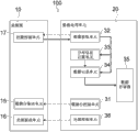
First will describe with the configuration of actual image acquiring device of taking pictures tentatively taking pictures in this embodiment.Fig. 1 is according to the schematic diagram of the image acquiring device of the embodiment of the present invention.As shown in Figure 1, comprise microscope 10 and data processing unit 20 according to the image acquiring device 100 of this embodiment.Below will the configuration of microscope 10 and data processing unit 20 be elaborated.
[about the configuration of microscope 10]
Corresponding with the thickness direction of biological specimen SPL with the direction (z direction of principal axis) that glove surface is vertical.Corresponding with the in-plane vertical with thickness direction with the direction (x-y in-plane) that glove surface is parallel.
Optical system 12 is arranged in objective table 11 tops.Optical system 12 comprises object lens 12A, imaging len 12B, dichroic mirror 12C, utilizing emitted light optical filter 12D and exciting light optical filter 12E.Light source 13 comprises (for example) bulb, for example, silver-colored lamp or LED(light emitting diode), exciting light is applied in the fluorescence labels being attached on biological specimen SPL.
While obtaining the fluoroscopic image of biological specimen SPL, exciting light optical filter 12E is by having the light transmission of the excitation wavelength that excites glimmering look the light that only makes to send from light source 13, thus generation exciting light.Dichroic mirror 12C reflects the exciting light that sees through the incident of exciting light optical filter to object lens 12A.Exciting light is focused on biological specimen SPL by object lens 12A.Subsequently, object lens 12A and imaging len 12B amplify the image of biological specimen SPL with predetermined magnification, and enlarged image are imaged on the imaging surface of imageing sensor 14.
If it is upper that exciting light is applied to biological specimen SPL, the structural dyestuff that adheres to biological specimen SPL sends fluorescence.Fluorescence sees through dichroic mirror 12C via object lens 12A, and arrives imaging len 12B via utilizing emitted light optical filter 12D.Utilizing emitted light optical filter 12D absorbs object lens 12A amplification, sees through the light of exciting light optical filter 12E, and only makes a part for color rendition light see through wherein.The image of having lost the color rendition light of outer light is amplified by imaging len 12B, and is imaged on imageing sensor 14, as mentioned above.
Use (for example) CCD(charge-coupled image sensor) or CMOS(complementary metal oxide semiconductor (CMOS)) imageing sensor is as imageing sensor 14.Imageing sensor 14 comprise receive RGB(red, green, blue) light of look light is converted to the photoelectric conversion unit of electric signal, and as the colour imaging instrument that obtains coloured image from incident light.
[about the biological specimen SPL and the bright spot that are placed on objective table 11]
Fig. 2 shows microslide prepared by the biological specimen SPL(that places at objective table 11 from the side direction of objective table 11) schematic diagram.As shown in Figure 2, biological specimen SPL is (for example) several microns to tens microns at the thickness of z direction.In addition, biological specimen SPL is clipped between microslide SG and cover glass CG, and fixes by predetermined fixing means.The thickness of microslide SG is (for example) about 1mm.The thickness of cover glass CG is that (for example) approximately 0.15 is to 0.17mm.
Fluorochromine biological specimen SPL.Fluorescent dye is a kind of dyestuff that is sent fluorescence by the exciting light applying from same light source.The example of fluorescent dye comprises DAPI(4', the two amidino groups-2-phenylindones of 6-), SpAqua and SpGreen.
To biological specimen SPL dyeing, therefore fluorescence labels is attached in the target biological tissue 50 of biological specimen SPL.If apply predetermined exciting light in fluorescence labels, fluorescence labels is sent predetermined fluorescence.Therefore, in the case of generating fluoroscopic image by the image of taking biological specimen SPL, bright spot (hereinafter referred to as " the fluorescence labeling 55 ") mark of target biological tissue 50 use demonstration predetermined colors.
[about the configuration of data processing unit]
Fig. 3 is the block diagram of the hardware configuration of data processing unit 20.Data processing unit 20 comprises computing machine, for example, and PC(personal computer).The fluoroscopic image of the biological specimen SPL that data processing unit 20 obtains imageing sensor 14 is stored as arbitrary format (for example, JPEG(JPEG (joint photographic experts group))) Digital Image Data.
As shown in Figure 3, data processing unit 20 comprises CPU(central processing unit) 21, ROM(ROM (read-only memory)) 22, RAM(random access memory) 23, operation input block 24, interface unit 25, display unit 26 and storer 27, these pieces connect by bus 28.
The multiple programs of ROM22 fixed storage, for example, for carrying out firmware and the data of various processing.RAM23, as the perform region of CPU21, stores OS(operating system temporarily), various application programs and the various types of data to be processed carried out.
Storer 27 comprises, for example, HDD(hard disk drive), flash memory, or another kind of nonvolatile memory, for example, solid-state memory.Storer 27 is stored OS, various application and various types of data.In this embodiment, especially, storer 27 is also stored the image of the fluoroscopic image data of catching from imageing sensor 14 or the image processing of carrying out fluoroscopic image data and is processed application program.
Interface unit 25 is connected with the control panel (objective table driver element 15, light source driving units 16 and shooting control module 17) of the objective table 11, light source 13 and the imageing sensor 14 that drive respectively microscope 10, and between control panel and data processing unit 20, exchanges signal by scheduled communication standard.
CPU21 by extension corresponding with the order of sending of operation input block 24 among multiple programs of storage in ROM22 or storer 27 to RAM23, and as required based on extender control display unit 26 and storer 27.
Operation input block 24 comprises operating means, for example, comprises indicating device, keyboard and the touch pad of mouse.
Display unit 26 comprises (for example) liquid crystal display, EL(electroluminescence) display, plasma display or CRT(cathode-ray tube (CRT)) display.Display unit 26 can be incorporated in data processing unit 20, or outside is connected to data processing unit 20.
[about the PROCESS OVERVIEW (tentatively taking pictures) that obtains biological specimen image]
In this embodiment, in order to search for focal position to carry out actual taking pictures, move in the scope of taking pictures the focal position of optical system 12, and this scope of taking pictures comprises that the middle biological specimen SPL that tentatively takes pictures is by the thickness partly of being taken pictures.During move focal position, imageing sensor 14 is exposed, therefore obtain the fluoroscopic image of tentatively taking pictures of biological specimen SPL.Based on the fluoroscopic image of tentatively taking pictures, calculate the distributed intelligence of the fluorescence labels in target thickness direction of taking pictures.The distributed intelligence of fluorescence labels is corresponding with the distributed intelligence of the target biological tissue 50 with fluorescence labeling 55 marks.
Based on the distributed intelligence of calculating, can be easy to (for example) and according to circumstances calculate the focal position that is used for the image of taking fluorescence labeling 55.Therefore, can take efficiently the image of the biological specimen SPL that has adhered to fluorescence labeling 55.Below will be described in detail.
[about the functional block (tentatively taking pictures) of process of obtaining biological specimen image]
The CPU21 of data processing unit 20 enters the extension corresponding order of sending with operation input block 24 among multiple programs of storage in ROM22 or storer 27 in RAM23.The program (image acquisition program) of CPU21 based on expansion carried out the process of obtaining biological specimen image.
Fig. 4 is the functional block diagram that obtains the process of biological specimen image.Data processing unit 20 comprises objective table control module 31(mobile control unit), image acquisition unit 32(generation unit), distributed intelligence computing unit 33(computing unit), data record unit 34, data-carrier store 35 and light source control unit 36.
Objective table control module 31(is for example) moving stage 11 in order, so that the part (below also referred to as sample portion) of being taken pictures of biological specimen SPL is positioned at the scope of taking pictures, and biological specimen SPL is assigned to and is taken pictures in scope AR, as shown in Figure 5.It should be noted, in Fig. 5, do not have overlappingly although will be assigned to the region of the biological specimen SPL taking pictures in scope AR, a part for adjacent area may be overlapping.
In addition, in the time that imageing sensor 14 is exposed, objective table control module 31 is simultaneously and integratedly at x direction of principal axis, y direction of principal axis and z direction of principal axis moving stage 11, to take the fluoroscopic image for adjusting focal position.Below will describe bodily movement method.
Each target sample part is by the movement of objective table 11 taking pictures while moving in scope AR, and image acquisition unit 32 sends to taking control module 17 order that imageing sensor 14 is exposed, to take the fluoroscopic image for adjusting focal position.
While completing the shooting of the fluoroscopic image for adjusting focal position, image acquisition unit 32 obtains the fluoroscopic image of the focal position for adjusting sample portion by taking control module 17 from imageing sensor 14 at every turn.Subsequently, image acquisition unit 32 is by utilizing predetermined coupling algorithm to the image that is distributed in the sample portion in scope AR of taking pictures is coupled, thereby generates the image of whole biological specimen.
Distributed intelligence computing unit 33 obtain based on image acquisition unit 32 for adjusting the fluoroscopic image of focal position of biological specimen SPL, calculate the distributed intelligence of fluorescence labeling 55 on the thickness direction of sample portion.
In addition, data record unit 34 receives the distributed intelligence that distributed intelligence computing unit 33 calculates, and the data relevant to sample data are stored in data-carrier store 35.
Data-carrier store 35 can be stored the data (for example, fluorescently-labeled area, quantity and type) of the measurement result of (for example) distributed intelligence computing unit 33 to fluorescence labeling 55, biological specimen SPL sample collector's name, sample collector's the information such as sex and age, date collected.
Above the functional block diagram of the process of obtaining biological specimen image is illustrated.
[about the movement of objective table 11]
Now will the movement of two of objective table 11 types be summarized.In the movement of a type of objective table 11, objective table 11 moves at x direction of principal axis or y direction of principal axis in order, in order each part of biological specimen SPL is tentatively taken pictures in x-y plane.This movement is moved as shown in Figure 5.
Then, carry out the movement of a type and a new portion of biological specimen SPL at every turn and be positioned at while taking pictures scope, carry out the movement of objective table 11 another kind of types.The movement of objective table 11 another kind of types is, when imageing sensor 14 is exposed, to carry out objective table 11 at x direction of principal axis, y direction of principal axis and the axial integrated moving of z, to take the fluoroscopic image for adjusting focal position.Below the method for taking the fluoroscopic image for adjusting focal position when being another kind of type mobile for objective table 11 is described.
[about the method for taking the fluoroscopic image for adjusting focal position]
To objective table 11 movements of every type carry out the shooting of the fluoroscopic image for adjusting focal position, movement and the image acquisition unit 32 of objective table control module 31 to objective table 11 synchronously carries out the exposure of imageing sensor 14.
Objective table control module 31 is by x-y in-plane and z direction of principal axis moving stage 11 and with respect to the focus of sample portion moving optical system.In this embodiment, because the movement of objective table 11 is controlled, so focus is mobile with the in-plane (x-y in-plane) vertical with thickness direction at the thickness direction (z direction of principal axis (optical axis direction of object lens 12A)) of sample portion.
As a specific example, objective table control module 31 is according to the position of following formula moving stage 11.
[mathematical formulae 1]
As shown in following formula (1) and (2), objective table 11 take constant speed in x-y plane along centre coordinate as (x0, y0), the circle that radius is R moves.If can take the image of taking pictures in scope AR, the large I of the position of centre coordinate (x0, y0) and radius R arranges arbitrarily.
But, if radius R is too little, be difficult to the bright spot image in focusing focus hereinafter described and image internal defocusing bright spot image to separate.Therefore, radius R need to than focus on time bright spot size much bigger.Especially, because the size of green focus chart picture in the NA situation that is 0.8 is about 0.3 μ m, so expect that the value of radius R should be more much bigger than the size of bright spot image, for example, be greater than the value of 2 to 3 μ m.
In formula (1) and (2), t
exrepresent time shutter section.Especially, when imageing sensor 14 exposes, objective table 11 moves with circular trace.In other words, in this embodiment, in the time that objective table 11 moves with circular trace, imageing sensor 14 is exposed.
As shown in formula (3), objective table 11 also moves along z direction of principal axis.In the time shutter of imageing sensor 14 section, objective table 11 is using constant speed from the z as mobile reference position
startmove to the z as mobile final position
end.
Subsequently, certainly starting moving stage 11 to take for adjusting the fluoroscopic image of focal position, during completing the movement of objective table 11, image acquisition unit 32 sends to taking control module 17 order that imageing sensor 14 is exposed.
Fig. 6 A and 6B are the mobile schematic diagram of the focal position of optical system in objective table 11 situation about moving.As shown in Figure 6, the focusing surface FP that comprises focal position is along z direction of principal axis from z
startto z
endmobile.In addition, focusing surface FP is mobile around centre coordinate (x0, y0) in x-y plane with circular trace.
Below will the moving method of objective table 11 be elaborated.
Fig. 7 be due to when exposure objective table 11 movement changed focal position and made the shape of the image that imageing sensor 14 takes and the schematic diagram that position changed along with the time.The change in location of image represents with track 41.
As shown in Figure 7, objective table control module 31 at z direction of principal axis from top to bottom with constant speed moving stage 11, and in x-y plane with constant speed with circular trace moving stage 11.From starting to be exposed between exposure period, the state that object lens 12A does not focus on the fluorescence labeling 55 being bonded on specific gene becomes focus state, and again becomes non-focusing state.
Especially, in exposure reference position, the out-of-focus image 40 of what fluorescence labeling sent have round-shaped color rendition light is taken on imageing sensor 14.
Subsequently, when the time shutter, section finished, this image focuses on gradually, if the z axial coordinate z of the image in exposure reference position
startrepresent the z axial coordinate z of the locational image of end exposure
endrepresent time shutter section t
exrepresenting, is (z at the z of image axial coordinate
end+ z
start)/2 and time shutter section are t
ex/ 2 o'clock, focusedimage 42 was taken on imageing sensor 14.Under focus state, the image of what fluorescence labeling sent have round-shaped color rendition light is less, edge clear, and brightness is higher.
If time shutter section finishes again, image becomes out-of-focus image again, and the out-of-focus image 43 of what fluorescence labeling sent have round-shaped color rendering light is taken by imageing sensor 14 in end exposure position.
As mentioned above, on imageing sensor 14, exposure image 40 to 43 in order, takes the image with semicircular in shape.
Above the method for taking the fluoroscopic image for adjusting focal position is illustrated.
[about repeating shooting in Z-direction for adjusting the fluoroscopic image of focal position]
Take while being used for adjusting the fluoroscopic image of focal position, as mentioned above, the axial focal position of z is from z
startto the z as mobile final position
endmobile.But the axial movement of z needn't once cover the axial whole scope of taking pictures of z.Therefore, the axial scope of taking pictures of z is divided into multiple scopes, repeatedly takes the fluoroscopic image for adjusting focal position.
Fig. 8 A and 8B are and describe in detail according to the schematic diagram of the moving range of the focal position of this embodiment.As shown in Figure 8, in this embodiment, multiple scopes of taking pictures (Zscan_1 to 3) of cutting apart are set, multiple scopes of taking pictures of cutting apart obtain by the range L of taking pictures of cutting apart the thickness range T that at least comprises sample portion at z direction of principal axis.Cut apart in the scope of taking pictures each, take the fluoroscopic image for adjusting focal position.Especially, cut apart in the scope of taking pictures each, z is set
start(1 to 3) and z
end(1 to 3) (seeing Fig. 8 B).
In Z-direction, cut apart the scope of taking pictures and be of a size of, for example, 20 μ m to 50 μ m.But size is not limited to this value.In addition, the quantity of cutting apart the scope of taking pictures does not also limit.In addition, the size that at least comprises the range L of taking pictures of the thickness range T of sample portion does not also limit.
Predetermined sample part being assigned under the state of taking pictures in scope AR, move in multiple each that cut apart in the scope of taking pictures focal position.Subsequently, for each scope of taking pictures of cutting apart is obtained the fluoroscopic image for adjusting focal position.In this embodiment, because the scope of taking pictures is divided into three scopes at z direction of principal axis, so obtain three fluoroscopic images for adjusting focal position with respect to predetermined sample part.
For example, can under the state that distributes predetermined sample part, take in order three fluoroscopic images.Alternately, use one to cut apart the scope of taking pictures and take after the image of whole biological specimen SPL, can take another and cut apart the image in the scope of taking pictures.
[for adjusting the concrete example of fluoroscopic image of focal position]
Fig. 9 is the schematic diagram (Zscan_1 to 3) of the fluoroscopic image of the sample portion of taking in multiple each that cut apart in coverage.In addition, Figure 10 has shown the captured photo corresponding with each fluoroscopic image shown in Fig. 9, as the example of this embodiment.These photos be radius R take circular trace as 15 μ m, z direction of principal axis (z
end-z
start) amount of movement be 20 μ m, the time shutter section of imageing sensor 14 is the fluoroscopic image that the condition of 1 second is taken as photographical condition.In addition, according to circumstances adjust the photographical condition such as gamma value.
Cutting apart the scope Zscan_1 and 3 that takes pictures is the scopes of taking pictures that do not comprise fluorescence labeling 55 at z direction of principal axis.Therefore,, in the image_Zscan1 and 3 of the fluoroscopic image as taking within the scope of this, the image defocus of fluorescence labeling 55 is serious (situation of Zscan_1 and Zscan_3 in each figure) very.
On the other hand, as cutting apart in the image_Zscan2 of the fluoroscopic image of taking in the scope Zscan_2 that takes pictures, move in the scope that comprises the position with fluorescence labeling 55 focal position.Therefore,, in the image_Zscan2 taking, the image of the track that shooting fluorescence labeling 55 focuses on along with the movement of focal position, as shown in the situation of Zscan_2 in each figure.
[about the distributed intelligence computation process of fluorescence labeling 55]
Next the distributed intelligence computation process to fluorescence labeling 55 is described.
Based on multiple fluoroscopic images of taking, calculate the distributed intelligence of fluorescence labeling 55 on sample portion thickness direction in multiple each that cut apart in the scope of taking pictures (Zscan_1 to 3).As mentioned above, calculated by distributed intelligence computing unit 33.
Figure 11 is the process flow diagram of the example of distributed intelligence computing unit 33 computation process of carrying out.
First, distributed intelligence computing unit 33 is to carrying out frequency analysis (step 101) at each multiple fluoroscopic images of taking in the scope of taking pictures (Zscan_1 to 3) of cutting apart.
Calculate thus each the spatial frequency in multiple fluoroscopic images (image_Zscan1 to 3).
Next, distributed intelligence computing unit 33 compares the maximum frequency component of fluoroscopic image mutually, selects the highest fluoroscopic image (step 102) of maximum frequency component.
In fluoroscopic image image_Zscan1 and 3, the image defocus of fluorescence labeling 55.On the other hand, in fluoroscopic image image_Zscan2, shown the focusedimage of the track of fluorescence labeling 55.Therefore,, in step 102, select fluoroscopic image image_Zscan2 as the highest fluoroscopic image of maximum frequency component.
Next, distributed intelligence computing unit 33 is analyzed the trace image (step 103) of fluorescence labeling 55 in the fluoroscopic image image_Zscan2 that maximum frequency component is the highest.
Especially, in this embodiment, quantity and the shape of fluorescence labeling 55 in analysis of fluorescence image image_Zscan2 in this step.Hereinafter, this analysis is called fluorescence labeling shape analysis.By shape analysis, obtain the exposure reference position z of fluorescently-labeled shape
startand the angle θ between focusedimage 60.Below will be described in detail.
Finally, distributed intelligence computing unit 33 is based upon the exposure reference position z that each fluorescence labeling 55 calculates
startand the angle θ between focusedimage 60, the distributed intelligence (step 104) of calculating each fluorescence labeling 55 on sample portion thickness direction.
Especially, in this embodiment, for each fluorescence labeling 55 calculates the positional information on z direction of principal axis.Therefore, can calculate the distributed intelligence of multiple fluorescence labelings 55.
Above the distributed intelligence computing method of fluorescence labeling 55 are illustrated.
[about fluorescently-labeled shape analysis and marker color]
Marker color in the shape analysis of during now by distributed intelligence to calculating fluorescence labeling 55, fluorescence labeling being carried out describes.
In the fluoroscopic image image_Zscan2 that distributed intelligence computing unit 33 obtains image acquisition unit 32, the fluorescence labeling 55(of labels targets biological tissue 50 is below also called " target indicia ", is described as fluorescence labeling 55a) detect.
On distributed intelligence computing unit 33, by (for example) target indicia show color (hereinafter referred to as " target indicia color ") and hereinafter referred to as " the core mark " of fluorescence labeling 55(of labeled cell core) demonstration color (hereinafter referred to as core marker color) be set to configuration information.
In addition, using hereinafter referred to as " control mark " of fluorescence labeling 55(that carries out mark to electing the gene of controlling gene as, be described as fluorescence labeling 55b) situation under, the gene dosage of electing controlling gene as existing in normal cell core also arranges on distributed intelligence computing unit 33.In addition, in this case, the color (hereinafter referred to as " control mark color ") of the fluorescence labeling demonstration of marking of control gene is also set.
According to the service conditions such as the manufacturer of the probe for fluorescent dye and fluorescence labeling type being determined clearly to configuration information.Especially, for example, use the HER-2DNA probe box that Japanese Abbott Laboratories company limited manufactures in the case of (), the target indicia color of HER2 gene is made as " redness ", and core marker color is made as " blueness ".In addition, in this case, on chromosome, the gene adjacent with HER2 gene is controlling gene, and the control mark color of controlling gene is made as " green ".
Each marker color that distributed intelligence computing unit 33 arranges by demonstration also detects the shape (area) and the quantity that detect fluorescence labeling 55 higher than the brightness of threshold value.Subsequently, the shape of analysis of fluorescence mark 55, the distributed intelligence of calculating thus multiple fluorescence labelings 55.
[about fluorescently-labeled shape analysis (concrete example)]
The concrete example of during now by distributed intelligence to calculating fluorescence labeling 55, fluorescently-labeled shape being analyzed describes.
In the case of the Zscan_2 shown in Fig. 9, the track obtaining by the image of taking two fluorescence labeling 55a and 55b with said method is carried out to graphic extension as example.As mentioned above, while movement in the focal position of optical system 12, imageing sensor 14 is exposed, thereby take fluoroscopic image image_Zscan2.
Because move with circular trace in the x-y of the in-plane as objective table 11 plane focal position, fluorescence labeling 55a and 55b move along circular O.Especially, the track of fluorescence labeling 55a and 55b is from the z of the mobile reference position as focus
startto the z as mobile final position
endmove (situation that move with semicircle in time shutter section focal position has been described) herein with semi-circular movement.
The focal position of optical system 12 moves up at z direction of principal axis cutting apart in the scope Zscan_2 that takes pictures.On any focal position during movement, it is more approaching focuses in one of them of fluorescence labeling 55a and fluorescence labeling 55b.Focusing under best state, the image area minimum of fluorescence labeling 55a and 55b, brightness is the highest.The image of area minimum is called focusedimage 60.
In this embodiment, distributed intelligence computing unit 33 calculates reference position z
startand the angle θ between focusedimage 60, and the distributed intelligence of calculating fluorescence labeling 55 on sample portion thickness direction based on angle θ.Below the example of the computing method of diagonal angle θ is described.
For example, the fluorescence labeling 55b shown in the situation of the Zscan_2 in Fig. 9, due to the center of the track of the fluorescence labeling 55b of focusedimage 60 in moving with semi-circular movement, angle θ is about 90 degree.In this case, when focal position moves to the center of cutting apart the scope Zscan_2 that takes pictures, its more approaching focusing.Therefore, can find out, fluorescence labeling 55b is positioned at the center of cutting apart the scope Zscan_2 that takes pictures.
The in the situation that of another fluorescence labeling 55a, compared with the track center of the fluorescence labeling 55a moving with semi-circular movement, focusedimage 60 is in more close final position z
endposition.Angle θ is about 135 degree.In this case, focal position moves to outside the center of cutting apart the scope Zscan_2 that takes pictures and in the time of its top, its more approaching focusing.Therefore, can find out, fluorescence labeling 55a is positioned at the top of cutting apart the scope Zscan_2 that takes pictures.
Especially, along with exposure reference position z
startand the angle θ between focusedimage 60 becomes less, and fluorescence labeling 55 is positioned at the closer to reference position z
startposition.Especially, in biological specimen SPL, fluorescence labeling 55 is positioned at the side near objective table 11.
On the other hand, along with exposure reference position z
startand the angle θ between focusedimage 60 becomes larger, and fluorescence labeling 55 is positioned at the closer to final position z
endposition.Especially, in biological specimen SPL, fluorescence labeling 55 is positioned at the side away from objective table 11.
It should be noted, explanation supposition objective table 11 above moves with constant speed in z direction of principal axis and x-y plane.But the movement of objective table 11 in z direction of principal axis and x-y plane not necessarily carried out with constant speed.It should be noted, in this case, need to set in advance the amount of movement of objective table 11 in x-y plane, that is, and the relevant information of the one-one relationship between angle θ and the objective table amount of movement on z direction of principal axis, and store this information.
Above the concrete example of fluorescently-labeled shape analysis is illustrated.
[about exposure reference position z
startand the calculating of the angle θ between focusedimage 60]
The computing method of the angle θ carrying out during now by distributed intelligence to calculating fluorescence labeling 55 describe.
Figure 12 is the exposure reference position z according to this embodiment
startand the schematic diagram of the example of the computation process of the angle θ between focusedimage 60.
First, distributed intelligence computing unit 33 is wanted the image (step 201) of analyzed fluorescence labeling 55 by cutting process from fluoroscopic image 70 cutting for adjusting focal position.
To theoretical image with cut image 75 and carry out matching process.As shown in figure 12, in this embodiment, the file of theoretical image is pre-stored in storer 27 grades.In file, store the multiple theoretical image 80 associated with all angles of 0 to 359 degree.In this embodiment, the size of associated angle is the identification number of theoretical image 80.
Can according to circumstances set in advance wavelength for creating theoretical image 80, numerical aperture, magnification, pel spacing etc.In addition, the angle that is made as 0 degree also can be according to circumstances set, theoretical image etc. is prepared in the angle of every how many degree.For example, being every 1 degree prepare theoretical image 80 in the situation that, 360 theoretical image 80 have been created.
Next, distributed intelligence computing unit 33 calculates multiple theoretical image 80 and cuts the related coefficient (step 202) between image 75.
Subsequently, distributed intelligence computing unit 33 calculates the identification number (step 203 is shown in the chart of Figure 11) of the theoretical image 80 that related coefficient is the highest.
Finally, distributed intelligence computing unit 33 calculates for the identification number of catching the theoretical image 80 that in multiple fluorescence labelings 55 of image 70, related coefficient is the highest, generate the list of identification numbers associated with multiple fluorescence labelings 55, and make the store list (step 204) such as storer 27.
In said method, the identification number (angle) of the theoretical image 80 based on calculating according to each fluorescence labeling 55 suitably calculates above-mentioned reference position z
startand the angle θ between focusedimage 60.For example, can prepare theoretical image 80, make angle θ corresponding with the angle as identification number.Alternately, by determine the shape of fluorescence labeling 55 as the angle of identification number, can again calculate subsequently reference position z
startand the angle θ between focusedimage 60.It should be noted reference position z
startand the computing method of the angle θ between focusedimage 60 are not limited to said method, can adopt additive method.
Above the computing method of diagonal angle θ are illustrated.
[about the concrete example and the method that use fluorescently-labeled distributed intelligence]
Now will the concrete example and the method that use fluorescently-labeled distributed intelligence be described.
Figure 13 to 15 is the example chart of the distributed intelligence of multiple fluorescence labelings 55.As mentioned above, the distributed intelligence of fluorescence labeling 55 can be generated as the data of histogram form.In these charts, transverse axis represents that fluorescence labeling 55 is in the axial position of z, and Z-axis represents the quantity of fluorescence labeling 55.
In this embodiment, transverse axis is separated by a half-size scale (F/2) of object lens depth of focus F, counts the quantity of the fluorescence labeling 55 comprising in each scope.The resolution of transverse axis is not limited to F/2, and the value that is less than depth of focus can be according to circumstances set.In addition, the value that is greater than depth of focus also can be set.
Especially, if the focal position of optical system 12 is located in the scope of transverse axis, take the focusedimage of the fluorescence labeling 55 comprising within the scope of this.Take the out-of-focus image of the fluorescence labeling 55 comprising within the scope of another, because it is away from focal position.
Take the image of biological specimen SPL based on this distributed intelligence of fluorescence labeling 55.Due to can be with reference to the distribution of fluorescence labeling 55, take pictures so actual and can and take pictures purposes efficiently and accurately carry out according to exposal model.
For example, suppose that object is at the actual middle shooting fluoroscopic image of taking pictures, thus in the multiple fluorescence labelings 55 that make to exist in biological specimen SPL only the fluorescence labeling 55 of specific quantity need focus on.In this case, as shown in figure 13, determine and only need to carry out actual taking pictures, focus on thering is the position A comprising in the scope of maximum fluorescence mark 55 quantity.Thus, can in actual taking pictures, accurately take fluoroscopic image.
In addition, for example, suppose that object is to observe quantitatively quantity or the type etc. of whole fluorescence labelings 55 that biological specimen SPL comprises.In this case, as shown in figure 14, by calculating the residing gamut B of fluorescence labeling 55 according to distributed intelligence, and gamut B is scanned, can take the fluoroscopic image that comprises all fluorescence labelings 55.
In addition, can be by imageing sensor 14 being exposed and takes a fluoroscopic image in the time that focal position being moved to final position from the reference position of gamut B.In addition, focal position can be moved in the spreading range C by obtaining at the both sides of gamut B increase predetermined edge M.Take thus the fluorescence labeling 55 and the out-of-focus image (defocusing degree almost similar) of fluorescence labeling 55 that is positioned at end at the center that is positioned at gamut B.Especially, owing to having taken the image of whole fluorescence labelings 55 with almost similar size and brightness, can improve the measurement precision of fluorescence labeling 55.
Have a kind of exposal model that is called so-called Z-stack stacking-type, under this pattern, multiple fluoroscopic images are taken to a sample portion in the different focal positions on z direction of principal axis.In the situation that implementing Z-stack stacking-type, can according to circumstances use distributed intelligence equally.For example, by the gamut B with reference to shown in Figure 14, determined the scope of implementing Z-stack stacking-type.In addition, can according to circumstances with reference to chart, the interval between different focal positions, the number of times etc. of taking pictures be set.For example, can implement Z-stack stacking-type according to the scope of separating transverse axis.As mentioned above, by with reference to distributed intelligence, can high precision take fluoroscopic image.
In addition, as shown in figure 15, the distribution plan that can imagine fluorescence labeling 55 is divided into the situation of two chevron parts.The concrete example of this situation comprises that the distribution of fluorescence labeling 55 concentrates near the situation of two diverse locations.In this case, owing to only needing the fluorescence labeling 55 to specific quantity to focus on, if taken pictures in center, taking pictures may be failed.
With reference to distributed intelligence, position D and position E that chevron part is comprised calculate as focal position.By focusing on and carrying out taking pictures for twice, can in actual taking pictures, successfully take fluoroscopic image with high precision on these two positions.
Above the concrete example and the method that use fluorescently-labeled distributed intelligence are illustrated.
[the present invention's general introduction]
Hereinbefore, according in the image acquiring device 100 of this embodiment, move in the range L of taking pictures that at least comprises sample portion thickness range T the focal position of optical system 12.During movement, imageing sensor 14 is exposed, obtain the fluoroscopic image of biological specimen SPL.Based on the fluoroscopic image of biological specimen SPL, calculate the distributed intelligence of the upper fluorescence labeling 55 of thickness direction (z direction of principal axis) of sample portion.Thus, can be easy to the focal position that (for example) suitably calculates the image for taking fluorescence labeling 55 according to exposal model and the purposes of taking pictures.Therefore, can take efficiently the image of the biological specimen SPL that has adhered to fluorescence labeling 55.
[the problems of the prior art (problem of the number of times of taking pictures)]
For example, suppose (for example) by every turn when being less than the change focal position, interval of depth of focus photographic images search for focal position, and analyze the method for each captured image.The method need to be taken many images, need to be useful on the mass storage of the data of a large amount of captured images of storage.In addition, because the method need to be calculated focal position based on the data of multiple images, a large amount of man-hours have therefore been spent, inefficiency.
Especially, in the situation that NA is 0.8, depth of focus is about 1 μ m.Subsequently, suppose by focal position is changed (for example 1 μ takes multiple images m) time with search focal position, and analysis image, thus search focal position.In this case, if measured while focal position being changed to 1 μ m in the scope that is greater than 50 μ m, need to take 50 above images, and by its storage.Using 24M pixel, in the situation of the imager of 14 bits, the capacity of an image file is about 100MB under tif form.Therefore,, owing to processing 50 above images with storer more than 5GB, process and become complicated.
[advantage (minimizing take pictures number of times) that the present invention obtains]
In this embodiment, as shown in Figure 8, Zscan_1 to 3 is made as to three and cuts apart the scope of taking pictures.As mentioned above, the scope that is greater than depth of focus is set, by the less number of times Computation distribution information of taking pictures.Thus, can search for focal position take pictures number of times in the situation that greatly reducing.
[by the larger reason of range L setting of taking pictures]
In Fig. 8 A, the range L of taking pictures (Zscan_1 and 3) that comprises the scope without biological specimen SPL is set.For example, as shown in figure 16, in some situation, accompany the dust 90(sizes such as hair and be about between microslide SG and objective table 11, for example, 20 μ m to 50 μ m).In this case, for example, if () arranges the thickness of only considering microslide SG while taking pictures range L, miss possibly focal position.Therefore, by according to circumstances arranging and comprise the range L of taking pictures of the scope without biological specimen SPL, distributed intelligence that can accurate Calculation fluorescence labeling 55.As mentioned above, owing to searching for focal position by the less number of times of taking pictures, can be by larger the range L setting of taking pictures.
[advantage (impact that elimination dust etc. causes) obtaining in the present invention]
At automatic search with adjust focal position in the situation that, may there is dust on imager or the defect of imager and be erroneously identified as the fluorescence bright spot on microslide GS, the positions different from true focal position are confirmed as the mistake of focal position.
In this embodiment, in the step 101 shown in Figure 11 and 102, calculate each spatial frequency of fluoroscopic image (image_Zscan1 to 3), select the highest image of maximum frequency.As mentioned above, by analysis frequency component and it is compared, can in the case of not being subject to the impact of dust, the defect of imager etc. on imager (imageing sensor 14), select the fluoroscopic image image_Zscan2 of the focusedimage 60 that comprises fluorescence labeling 55.
< modification 1(selects fluoroscopic image according to brightness) >
Be not limited to above-described embodiment according to embodiments of the invention, and can carry out various modifications.
Figure 17 is the process flow diagram of the modification of the distributed intelligence computing of the fluorescence labeling 55 that carries out of the distributed intelligence computing unit 33 shown in Figure 11.
In this modification, first, calculate the brightness (step 301) of each fluoroscopic image (image_Zscan1 to 3).
Subsequently, select the highest fluoroscopic image (step 302) of brightness.
Subsequently, selected fluoroscopic image is carried out to Fluorometric assay of fluorescence-labeled processing (step 303).
As mentioned above, can, based in multiple brightness of cutting apart each fluoroscopic image of taking in the scope of taking pictures, select the fluoroscopic image of the computing of carrying out distributed intelligence.Thus, can reduce calculated amount.
The take pictures merging of range L of < modification 2() >
In the above-described embodiments, as shown in Figure 8 A, the multiple scopes of taking pictures of cutting apart that obtain by cutting apart the range L of taking pictures are set, for each scope of taking pictures of cutting apart is taken fluoroscopic image.But, also can make to scan the whole range L of taking pictures during once photo taking by moving stage, generate fluoroscopic image.Subsequently, can calculate based on fluoroscopic image the distributed intelligence of fluorescence labeling 55.
For example, can within being about the range L of taking pictures of 100 μ m, size carry out once photo taking.Thus, can (for example) reduce calculated amount, increase processing speed.Whether size that can be based on the range L of taking pictures and the determine precision of imageing sensor 14 arrange cuts apart the scope of taking pictures.
< modification 3(determines exposal model based on distributing) >
Hereinbefore, to can suitably using the situation of distributed intelligence to be illustrated according to exposal model and the purposes of taking pictures.On the contrary, can select best exposal model and the purposes of taking pictures based on distributed intelligence.
For example, can carry out following deterministic process: in the situation that multiple fluorescence labelings 55 concentrate in focal depth range, select the fixing once photo taking in focal position, in the situation that multiple fluorescence labelings 55 disperse, select Z-stack stacking-type to take pictures.Now, for example, data processing unit 20 works the pattern determining unit of taking pictures.
< modification 4(is based on marker color Computation distribution information) >
In addition, only the target indicia (redness) in fluorescence labeling 55 or control mark (green) can be set as the calculating target of distributed intelligence.These settings can for example, be inputted by () user operation.
< modification 5(will calculate fluorescently-labeledly gradually goes out) >
In addition, and nonessential to all fluorescence labelings 55 calculating location informations in fluoroscopic image.Especially, fluorescence labeling 55 is gradually few, and selected, can position-based information Computation distribution information.
< modification (other) >
It should be noted, according in the configuration of the microscope 10 of above-described embodiment, object lens 12A can be eyepiece.
In addition, in the above-described embodiments, although moving stage 11 is moved for moving focal point position, the also object lens 12A of movable optical system 12.
In the above-described embodiments, although data-carrier store 35 is located in data processing unit 20, the distributed intelligence of the image of biological specimen, fluorescence labeling 55 etc. is stored in data-carrier store 35, and it is also stored in external memory storage.
In order to connect microscope 10 and data processing unit 20, not only can use bus transmission path, also can use wired or wireless transmission medium, for example, LAN (Local Area Network), internet and digital satellite broadcasting.
< the second embodiment >
In a second embodiment, mainly supposition: the cell density of the biological specimen SPL that fluorescent microscope is taken is high, and cannot clearly identify each bright spot of the fluoroscopic image by cell dyeing being obtained by fluorescence labels.
In addition, even if can distinguish bright spot, but because the quantity of bright spot is larger, in the algorithm of the shape of the each bright spot track of the analysis described in the first embodiment, supposed the situation of the overlong time of analyzing cost.
Therefore, the present invention's being characterized as in a second embodiment, is considered as tissue by whole image and does not need to distinguish each bright spot of fluoroscopic image, and tissue is analyzed.By the method, compared with the situation of the algorithm of the shape of the each bright spot track of analysis described in the first embodiment, can in the situation that cell density is higher, shorten the processing time.
It should be noted, in explanation below, represent to be described by same numbers by the parts identical with the first embodiment, except as otherwise noted.
[about with the concrete difference of the first embodiment]
First by describing with the concrete difference of the first embodiment.With the concrete difference of the first embodiment be to describe angle θ in the first embodiment computing method [about exposure reference position z
startand the calculating of the angle θ between focusedimage 60] part of this paragraph.In the first embodiment, cut and cut image 75 from the fluoroscopic image 70 for adjusting focal position, and be the related coefficient of multiple theoretical image 80 of each each angular correlation that cuts image 75 calculating and 0 to 359 degree.
On the other hand, in this embodiment, will analyze as tissue for the whole fluoroscopic image of adjusting focal position, by any calculating angle θ in the method for two types hereinafter described.This is the main difference part in this embodiment.
The example of the difference relevant to the analysis of whole fluoroscopic image comprises, is different from the first embodiment, in this embodiment, can not obtain the distributed intelligence of each fluorescence labeling 55, can only obtain the mean place of all fluorescence labelings 55.
[about comprising actual whole flow process of taking pictures]
Now the flow process to whole process is described, take pictures to sum up tentatively, according to the analysis of the first embodiment, according to the relation between the analysis of the second embodiment and actual taking pictures.
Figure 18 is the process flow diagram that shows the flow process of whole process of the present invention, whole process comprise tentatively take pictures, according to the analysis of the first embodiment, according to the relation between the analysis of the second embodiment and actual taking pictures.
First, sample (microslide, biological specimen SPL) is placed on the objective table 11 of fluorescent microscope 10 (step 501).The placement of sample can be undertaken by transfer robot or manual operation.
Next, objective table control module 31 moving stages 11, so that the suitable position of biological specimen SPL approaches the scope AR(step 502 of taking pictures).
The movement of objective table 11 is movements of one type of the objective table 11 described in the first embodiment.In this step, the position of objective table 11 on z direction of principal axis is positioned at the exposure reference position z of the cut apart scope of taking pictures Zscan_1
start.
Next, objective table control module 31 and image acquisition unit 32 synchronous operations, to take the fluoroscopic image (step 503) for adjusting focal position.
This step is for tentatively taking pictures.The method of taking the fluoroscopic image for adjusting focal position is the method described in this paragraph of the first embodiment [about the method for taking the fluoroscopic image for adjusting focal position].
Next, distributed intelligence computing unit 33 is analyzed captured for adjusting the fluoroscopic image (step 504) of focal position.
Analysis comprises the method for the mean flow rate of obtaining fluoroscopic image and obtains the method that brightness value is the quantity of the bright spot more than threshold value setting in advance.
Herein, obtaining in the method for bright spot quantity, the bright pixel quantity of background value that can contrast fluoroscopic image is counted, and replaces bright spot quantity is counted.
Next, distributed intelligence computing unit 33 determines whether the mean flow rate obtained in step 504 or the quantity of bright spot are greater than the threshold value (step 505) setting in advance.
By bright spot quantity and threshold in the situation that, threshold value is about (for example) 100 conventionally.
Be less than ("No" in step 505) the threshold value setting in advance in the quantity of mean flow rate or bright spot, distributed intelligence computing unit 33 determines that the cell density in biological specimen SPL is lower, and the track of each bright spot is carried out to the images match described in the first embodiment, to calculate fluorescently-labeled distributed intelligence (step 506).
Be greater than ("Yes" in step 505) the threshold value setting in advance in the quantity of mean flow rate or bright spot, distributed intelligence computing unit 33 determines that the cell density in biological specimen SPL is higher, and whole fluoroscopic image is carried out to fabric analysis, as described in the second embodiment, thereby calculate fluorescently-labeled distributed intelligence (step 507).
If obtained fluorescently-labeled distributed intelligence in step 506 or 507, next, objective table control module 31 is at z direction of principal axis moving stage 11, to obtain the optimal focus position (step 508) definite by distributed intelligence.
Next, image acquisition unit 32 carries out actual take pictures (step 509).
For example, analyzed by observer's (, virologist) by the actual fluoroscopic image obtaining of taking pictures, and for diagnosis.
Next, data processing unit 20 determines whether to exist another position (step 510) of taking pictures.
In the situation that also existing another to take pictures position ("Yes" in step 510), process turns back to step 502 and continues.In the situation that not existing another to take pictures position ("No" in step 510), process completes.
The flow process to whole process of the present invention above, comprise tentatively take pictures, according to the analysis of the first embodiment, summarize according to the relation between the analysis of the second embodiment and actual taking pictures.
[about the principle that is considered as tissue and analyzes]
To the reason that can analyze the whole fluoroscopic image for adjusting the focal position that obtains of tentatively taking pictures be described now.
Have two reasons, first reason is to be embossed into peculiar shape by the overlapping track of the many bright spots of fluoroscopic image for adjusting focal position.
In the situation that cell density is higher, bright spot quantity is larger, and many bright spot tracks are overlapping in the fluoroscopic image of the middle shooting of tentatively taking pictures, and is therefore difficult to determine the image of the dark part that defocuses bright spot track.Subsequently, the highlights that only can determine the bright spot track that comprises focusedimage 60 in image divides.Therefore,, although that bright spot track is initially is circular or semicircle, only " bright spot track the brightest and be almost the part BL of straight line " is can determine that shape is stamped in fluoroscopic image.In this embodiment, this is definite principle.
Second reason be in sample portion as be distributed with fluorescence labeling 55 scope thickness and take the relative ratios for the scope of moving focal point position on z direction of principal axis when adjusting the fluoroscopic image of focal position.
The thickness of the sample portion of fluorescent dye is about 4 μ m to 6 μ m, and the bright spot of fluorescence labeling 55 is only distributed in this thickness range.On the other hand, while taking the fluoroscopic image for adjusting focal position, focal position mobile scope on z direction of principal axis is for example 20 μ m to 50 μ m.
As mentioned above, large several times to ten times than the scope that is distributed with fluorescence labeling 55 of the scopes that move at z direction of principal axis focal position.In the situation that this ratio is larger, be distributed with position in the scope of fluorescence labeling 55 in the relatively little scope of changeability.
Therefore, the changeability of " bright spot track the brightest and be almost the part BL of straight line " shown angle θ is considered to less.Therefore, by fluoroscopic image is analyzed as tissue, and obtain the mean value of the angle θ that " bright spot track the brightest and be almost the part BL of straight line " show, can obtain the average height of fluorescence labeling 55 on z direction of principal axis,, the position on the z direction of principal axis that has focused on many bright spots.
Above describe about the principle that fluoroscopic image is considered as to tissue and tissue is analyzed.
[obtaining the method (first) of angle θ by fabric analysis]
Below will the first method of obtaining angle θ by fabric analysis be described.
In the method, be identified for obtaining frequency component to adjust the multiple directions of the focal position obtaining in tentatively taking pictures for fluoroscopic image.Subsequently, obtain the frequency component of determining in direction, and angle θ in the highest direction of definite maximum frequency component.
Figure 19 is the horizontal direction that wherein x direction of principal axis is fluoroscopic image, and the vertical direction that y direction of principal axis is fluoroscopic image is defined as the schematic diagram of the direction that obtains frequency component with respect to the tilt direction A of 45 degree of x and y direction of principal axis.As mentioned above, the direction quantity of obtaining frequency component is preferably more than three.The direction number amount of obtaining frequency component depends on the accuracy of target angle (target angel) θ.
Its reason is, the in the situation that of both direction, the direction of " bright spot track the brightest and be almost the part BL of straight line " is difficult to be determined uniquely.For example, as shown in figure 20, consider that " bright spot track the brightest and be almost the part BL of straight line " appears at the situation of the direction of pattern A and the direction of pattern B.In order to distinguish both direction and to determine correct direction, x direction of principal axis and this both direction of y direction of principal axis are inadequate.
By obtaining the fluoroscopic image frequency component of (comprising many " bright spot tracks the brightest and be almost the part BL of straight line " in as mentioned above definite direction), can determine which direction many pitch angle of " bright spot track the brightest and be almost the part BL of straight line " concentrate on.This is because the vertical direction through " bright spot track the brightest and be almost the part BL of straight line " is the direction that maximum frequency component is the highest.
For example, similar to the situation of the bright spot track of the fluorescence labeling 55a shown in the situation of the Zscan_2 in Fig. 9, suppose exposure reference position z
startthe angle at place is 0 degree, end exposure position z
endthe angle at place is 180 degree, and focusedimage 60 is positioned at 135 degree angle places.
In this case, the slope of " bright spot track the brightest and be almost the part BL of straight line " is identical with the locational tangent slope of focusedimage 60 in circle O, that is, and and 45 degree.Subsequently, the vertical direction (, the highest direction of maximum frequency component) through " bright spot track the brightest and be almost the part BL of straight line " is direction A(-45 degree direction).Can find out, according to exposure reference position z
startbe 0 degree and end exposure position z
endbe the relation of 180 degree, angle θ is about 135 degree.
Above the first method of obtaining angle θ by fabric analysis is illustrated.
[organizing the method (second) of obtaining angle θ by analysis]
Below will the second method of organizing to obtain angle θ by analysis be described.
In the method, the fluoroscopic image for adjusting the focal position that obtains of tentatively taking pictures 70, as original image, for multiple directions, is generated to the image that original image is obtained to the pixel of predetermined direction displacement predetermined quantity.Subsequently, obtain the correlativity between multiple images and the original image of generation.The direction of the image that correlativity is minimum is regarded as the vertical direction through " bright spot track the brightest and be almost the part BL of straight line ", determines thus angle θ.
Figure 21 A to 21E is respectively and shows original image and by the schematic diagram of the obtained state of the correlativity between the image that original image is obtained to the pixel of predetermined direction displacement predetermined quantity.To describe the second method with reference to the accompanying drawings now.
(1) first, distributed intelligence computing unit 33 obtains fluoroscopic image 70 for adjusting focal position as original image.
Original image, as shown in the upper left quarter of Figure 21, has been taken two " bright spot tracks the brightest and be almost the part BL of straight line " in image.It should be noted, owing to supposing the higher situation of cell density of biological specimen SPL in this embodiment, in fact in original image, taken more than 100 " bright spot track the brightest and be almost the part BL of straight line ".But, only shown two " bright spot tracks the brightest and be almost the part BL of straight line ", so that Figure 21 is more clear.
(2) next, distributed intelligence computing unit 33 generates the image by original image is obtained in the pixel of multiple directions top offset predetermined quantity.
Figure 21 A to 21E shows respectively original image at the state with every 45 degree of the scope intrinsic displacement at 0 to 180 degree in five directions of multiple directions.In Figure 21 A to 21E, the position that dotted line represents is the position of " bright spot track the brightest and be almost the part BL of straight line " before original image displacement.The angle and direction of original image displacement depends on the precision of target angle θ.
It should be noted, at the width of " bright spot track the brightest and be almost the part BL of straight line ", for example, for () 10 pixels, the intended pixel quantity of picture displacement is about 15 pixels conventionally.
(3) next, distributed intelligence computing unit 33 calculate original image and image that the pixel of original image displacement predetermined quantity is obtained between correlativity.
The example of correlation calculations method comprises the difference of each pixel between comparison original image and displacement diagram picture.The method is for the image of Figure 21 A to 21E.In the image shown in Figure 21 A and 21E, overlapping larger between " bright spot track the brightest and be almost the part BL of straight line " and the image B L' that obtains by displacement " bright spot track the brightest and be almost the part BL of straight line ", difference is less.Especially, correlativity is higher.
On the other hand, in the image of Figure 21 C, " bright spot track the brightest and be almost the part BL of straight line " and between " bright spot track the brightest and be almost the part BL of straight line " mobile image B L' obtaining, almost do not have by making overlapping, and difference maximum.Especially, correlativity is minimum.
(4) last, distributed intelligence computing unit 33 by the orientation determination of image minimum correlativity for vertical through the direction of " bright spot track the brightest and be almost the part BL of straight line ", and obtain angle θ.
In the image of Figure 21 C, because original image is to bottom offset, can find out, the angle directions of 90 degree or 270 degree are vertical directions through " bright spot track the brightest and be almost the part BL of straight line ".Therefore, if exposure reference position z
startthe angle at place is 0 degree, end exposure position z
endthe angle at place is 180 degree, and angle θ is about 90 degree.
Above the second method of organizing to obtain angle θ by analysis is illustrated.
[supplementary notes]
Embodiments of the invention are not limited to above-described embodiment, are not deviating under the prerequisite of purport of the present invention, can carry out various modifications.
Those skilled in the art will appreciate that and can carry out various modifications, combination, sub-portfolio and replacement according to designing requirement and other factors, as long as they are in the scope of claims or its equivalent.
Claims (5)
1. an image acquiring device, comprising:
Light source, is configured to generate the luminous exciting light of fluorescence labels that makes biological specimen;
Imageing sensor, is configured to form image;
Optical system, is configured to:
To be applied at least part of region of described biological specimen from the described exciting light of described light source, described subregion comprises described fluorescence labels, and
Make described imageing sensor form the fluoroscopic image of described subregion;
Mobile control unit, is configured to make the focal position of described optical system to move up with the side vertical with described optical axis at the optical axis direction of described optical system;
Generation unit, is configured to:
During move the focal position of described optical system, described imageing sensor is carried out to continuous exposure, and
Generate the time exposure image of described subregion; And computing unit, be configured to:
Analyze the frequency of the described time exposure image generating, and
At least utilize the result of described analysis to calculate the positional information on described optical axis direction of described fluorescence labels.
2. image acquiring device according to claim 1, wherein
Described computing unit is configured to:
Analyze from the both direction setting in advance and with described both direction the frequency of the described time exposure image in different at least one direction, described both direction is orthogonal,
Determine a direction in direction with highest frequency component, and
Positional information described in direction calculating based on definite.
3. image acquiring device according to claim 2, wherein,
Described computing unit is configured to:
The information of the correlativity between pre-stored direction and described positional information about being determined, and
Described information based on about described correlativity is from positional information described in determined direction calculating.
4. image acquiring device according to claim 2, wherein,
Described computing unit is configured to:
Generate mobile image, described mobile image is to obtain by making described time exposure image move for each direction the pixel quantity setting in advance,
Obtain the correlativity between described time exposure image and each mobile image, and
Determine the direction with minimum correlativity.
5. an image acquiring method, comprising:
Generation makes the luminous exciting light of the fluorescence labels of biological specimen;
By optical system, described exciting light is applied to at least part of region of described biological specimen and makes described imageing sensor form the fluoroscopic image of described subregion, described subregion comprises described fluorescence labels;
The focal position of described optical system is moved up with the side vertical with optical axis at the optical axis direction of described optical system;
During moving, the focal position of described optical system to described imageing sensor continuous exposure, and generates the time exposure image of described subregion; And
Analyze the frequency of the described time exposure image generating, and at least utilize the result of described analysis to calculate the positional information of described fluorescence labels on described optical axis direction.
Applications Claiming Priority (2)
| Application Number | Priority Date | Filing Date | Title |
|---|---|---|---|
| JP2012249208A JP5928308B2 (en) | 2012-11-13 | 2012-11-13 | Image acquisition apparatus and image acquisition method |
| JP2012-249208 | 2012-11-13 |
Publications (1)
| Publication Number | Publication Date |
|---|---|
| CN103808702A true CN103808702A (en) | 2014-05-21 |
Family
ID=50680798
Family Applications (1)
| Application Number | Title | Priority Date | Filing Date |
|---|---|---|---|
| CN201310547711.6A Pending CN103808702A (en) | 2012-11-13 | 2013-11-06 | Image Obtaining Unit And Image Obtaining Method |
Country Status (3)
| Country | Link |
|---|---|
| US (1) | US9322782B2 (en) |
| JP (1) | JP5928308B2 (en) |
| CN (1) | CN103808702A (en) |
Cited By (2)
| Publication number | Priority date | Publication date | Assignee | Title |
|---|---|---|---|---|
| CN109792486A (en) * | 2016-09-29 | 2019-05-21 | 株式会社尼康 | Photographic device |
| CN110836891A (en) * | 2018-08-17 | 2020-02-25 | 湖南爱威医疗科技有限公司 | Method, device and equipment for realizing rapid microscopic examination and computer readable storage medium |
Families Citing this family (7)
| Publication number | Priority date | Publication date | Assignee | Title |
|---|---|---|---|---|
| WO2015013605A1 (en) * | 2013-07-26 | 2015-01-29 | Abbott Point Of Care, Inc. | Method and apparatus for producing an image of undiluted whole blood sample having wright stain coloration |
| JP6547424B2 (en) * | 2015-06-01 | 2019-07-24 | コニカミノルタ株式会社 | Fluorescent image focusing system, focusing method and focusing program |
| JP6578928B2 (en) * | 2015-12-16 | 2019-09-25 | コニカミノルタ株式会社 | Focus position specifying system of fluorescent image, focus position specifying method, and focus position specifying program |
| JP6231709B1 (en) | 2016-05-31 | 2017-11-15 | シスメックス株式会社 | Fluorescence image analyzer and analysis method |
| US11004199B2 (en) * | 2016-11-11 | 2021-05-11 | University Of South Florida | Automated stereology for determining tissue characteristics |
| JPWO2018123677A1 (en) * | 2016-12-27 | 2019-12-12 | コニカミノルタ株式会社 | Image processing method and image processing system |
| JPWO2022059312A1 (en) * | 2020-09-17 | 2022-03-24 |
Family Cites Families (11)
| Publication number | Priority date | Publication date | Assignee | Title |
|---|---|---|---|---|
| JP3961729B2 (en) * | 1999-03-03 | 2007-08-22 | 株式会社デンソー | All-focus imaging device |
| JP3627020B2 (en) * | 2002-03-28 | 2005-03-09 | 独立行政法人産業技術総合研究所 | Three-dimensional transmission microscope system and image display method |
| JP2010540939A (en) * | 2007-09-26 | 2010-12-24 | マサチューセッツ インスティテュート オブ テクノロジー | High resolution 3D imaging of single semiconductor nanocrystals |
| JP5499732B2 (en) | 2009-06-23 | 2014-05-21 | ソニー株式会社 | Biological sample image acquisition apparatus, biological sample image acquisition method, and biological sample image acquisition program |
| US8294768B2 (en) * | 2009-11-23 | 2012-10-23 | Hon Hai Precision Industry Co., Ltd. | System and method for motion detection |
| US8570650B2 (en) * | 2009-12-09 | 2013-10-29 | Applied Precision, Inc. | Method and system for fast three-dimensional structured-illumination-microscopy imaging |
| JP2011180442A (en) * | 2010-03-02 | 2011-09-15 | Sony Corp | Device, method and program for acquisition of sample image |
| JP5589619B2 (en) * | 2010-07-01 | 2014-09-17 | ソニー株式会社 | Information processing apparatus, stage waviness correction method, and program |
| US20140125776A1 (en) * | 2011-05-25 | 2014-05-08 | Huron Technologies International Inc, | 3d pathology slide scanner |
| US20130093871A1 (en) * | 2011-10-18 | 2013-04-18 | Andreas G. Nowatzyk | Omnidirectional super-resolution microscopy |
| JP2013114042A (en) * | 2011-11-29 | 2013-06-10 | Sony Corp | Image acquisition device, image acquisition method and image acquisition program |
-
2012
- 2012-11-13 JP JP2012249208A patent/JP5928308B2/en active Active
-
2013
- 2013-10-22 US US14/059,791 patent/US9322782B2/en active Active
- 2013-11-06 CN CN201310547711.6A patent/CN103808702A/en active Pending
Cited By (2)
| Publication number | Priority date | Publication date | Assignee | Title |
|---|---|---|---|---|
| CN109792486A (en) * | 2016-09-29 | 2019-05-21 | 株式会社尼康 | Photographic device |
| CN110836891A (en) * | 2018-08-17 | 2020-02-25 | 湖南爱威医疗科技有限公司 | Method, device and equipment for realizing rapid microscopic examination and computer readable storage medium |
Also Published As
| Publication number | Publication date |
|---|---|
| US9322782B2 (en) | 2016-04-26 |
| JP5928308B2 (en) | 2016-06-01 |
| JP2014098575A (en) | 2014-05-29 |
| US20140131592A1 (en) | 2014-05-15 |
Similar Documents
| Publication | Publication Date | Title |
|---|---|---|
| CN103808702A (en) | Image Obtaining Unit And Image Obtaining Method | |
| ES2959361T3 (en) | Real-time autofocus scanning | |
| CN103134782B (en) | Image acquiring device and image acquiring method | |
| CN108982500B (en) | Intelligent auxiliary cervical fluid-based cytology reading method and system | |
| US8314837B2 (en) | System and method for imaging with enhanced depth of field | |
| JP6069825B2 (en) | Image acquisition apparatus, image acquisition method, and image acquisition program | |
| EP2941663B1 (en) | A method for automated platform and/or reference object independent acquisition of positional information and localization of objects of interest in a microscope | |
| JP5996334B2 (en) | Microscope system, specimen image generation method and program | |
| CN108139650A (en) | Real-time focusing in line scanning imagery | |
| US10073258B2 (en) | Microscope system | |
| US11347044B2 (en) | Low resolution slide imaging and slide label imaging and high resolution slide imaging using dual optical paths and a single imaging sensor | |
| CN102053355A (en) | System and method for imaging with enhanced depth of field | |
| US20110091125A1 (en) | System and method for imaging with enhanced depth of field | |
| CN105190686A (en) | Referencing in multi-acquisition slide imaging | |
| CN110991379B (en) | Algae counting method | |
| US7653260B2 (en) | System and method of registering field of view | |
| JP5343762B2 (en) | Control device and microscope system using the control device | |
| EP3816698B1 (en) | Digital pathology scanner for large-area microscopic imaging | |
| CN103175780A (en) | Automated imaging system of large-size serial section of biological tissue | |
| JP5942390B2 (en) | Image acquisition apparatus, image acquisition method, and image acquisition program |
Legal Events
| Date | Code | Title | Description |
|---|---|---|---|
| C06 | Publication | ||
| PB01 | Publication | ||
| C02 | Deemed withdrawal of patent application after publication (patent law 2001) | ||
| WD01 | Invention patent application deemed withdrawn after publication |
Application publication date: 20140521 |