CN103764265A - Multiple emulsions and techniques for the formation of multiple emulsions - Google Patents
Multiple emulsions and techniques for the formation of multiple emulsions Download PDFInfo
- Publication number
- CN103764265A CN103764265A CN201280039927.5A CN201280039927A CN103764265A CN 103764265 A CN103764265 A CN 103764265A CN 201280039927 A CN201280039927 A CN 201280039927A CN 103764265 A CN103764265 A CN 103764265A
- Authority
- CN
- China
- Prior art keywords
- fluid
- pipeline
- droplet
- shell
- approximately
- Prior art date
- Legal status (The legal status is an assumption and is not a legal conclusion. Google has not performed a legal analysis and makes no representation as to the accuracy of the status listed.)
- Pending
Links
Images


Classifications
-
- B—PERFORMING OPERATIONS; TRANSPORTING
- B01—PHYSICAL OR CHEMICAL PROCESSES OR APPARATUS IN GENERAL
- B01F—MIXING, e.g. DISSOLVING, EMULSIFYING OR DISPERSING
- B01F23/00—Mixing according to the phases to be mixed, e.g. dispersing or emulsifying
- B01F23/40—Mixing liquids with liquids; Emulsifying
- B01F23/41—Emulsifying
-
- B—PERFORMING OPERATIONS; TRANSPORTING
- B01—PHYSICAL OR CHEMICAL PROCESSES OR APPARATUS IN GENERAL
- B01F—MIXING, e.g. DISSOLVING, EMULSIFYING OR DISPERSING
- B01F25/00—Flow mixers; Mixers for falling materials, e.g. solid particles
- B01F25/14—Mixing drops, droplets or bodies of liquid which flow together or contact each other
-
- B—PERFORMING OPERATIONS; TRANSPORTING
- B01—PHYSICAL OR CHEMICAL PROCESSES OR APPARATUS IN GENERAL
- B01F—MIXING, e.g. DISSOLVING, EMULSIFYING OR DISPERSING
- B01F23/00—Mixing according to the phases to be mixed, e.g. dispersing or emulsifying
- B01F23/40—Mixing liquids with liquids; Emulsifying
- B01F23/41—Emulsifying
- B01F23/4105—Methods of emulsifying
-
- B—PERFORMING OPERATIONS; TRANSPORTING
- B01—PHYSICAL OR CHEMICAL PROCESSES OR APPARATUS IN GENERAL
- B01F—MIXING, e.g. DISSOLVING, EMULSIFYING OR DISPERSING
- B01F23/00—Mixing according to the phases to be mixed, e.g. dispersing or emulsifying
- B01F23/40—Mixing liquids with liquids; Emulsifying
- B01F23/41—Emulsifying
- B01F23/411—Emulsifying using electrical or magnetic fields, heat or vibrations
-
- B—PERFORMING OPERATIONS; TRANSPORTING
- B01—PHYSICAL OR CHEMICAL PROCESSES OR APPARATUS IN GENERAL
- B01F—MIXING, e.g. DISSOLVING, EMULSIFYING OR DISPERSING
- B01F23/00—Mixing according to the phases to be mixed, e.g. dispersing or emulsifying
- B01F23/40—Mixing liquids with liquids; Emulsifying
- B01F23/41—Emulsifying
- B01F23/414—Emulsifying characterised by the internal structure of the emulsion
- B01F23/4145—Emulsions of oils, e.g. fuel, and water
-
- B—PERFORMING OPERATIONS; TRANSPORTING
- B01—PHYSICAL OR CHEMICAL PROCESSES OR APPARATUS IN GENERAL
- B01F—MIXING, e.g. DISSOLVING, EMULSIFYING OR DISPERSING
- B01F25/00—Flow mixers; Mixers for falling materials, e.g. solid particles
- B01F25/30—Injector mixers
- B01F25/31—Injector mixers in conduits or tubes through which the main component flows
- B01F25/311—Injector mixers in conduits or tubes through which the main component flows for mixing more than two components; Devices specially adapted for generating foam
-
- B—PERFORMING OPERATIONS; TRANSPORTING
- B01—PHYSICAL OR CHEMICAL PROCESSES OR APPARATUS IN GENERAL
- B01F—MIXING, e.g. DISSOLVING, EMULSIFYING OR DISPERSING
- B01F25/00—Flow mixers; Mixers for falling materials, e.g. solid particles
- B01F25/30—Injector mixers
- B01F25/31—Injector mixers in conduits or tubes through which the main component flows
- B01F25/313—Injector mixers in conduits or tubes through which the main component flows wherein additional components are introduced in the centre of the conduit
-
- B—PERFORMING OPERATIONS; TRANSPORTING
- B01—PHYSICAL OR CHEMICAL PROCESSES OR APPARATUS IN GENERAL
- B01F—MIXING, e.g. DISSOLVING, EMULSIFYING OR DISPERSING
- B01F33/00—Other mixers; Mixing plants; Combinations of mixers
-
- B—PERFORMING OPERATIONS; TRANSPORTING
- B01—PHYSICAL OR CHEMICAL PROCESSES OR APPARATUS IN GENERAL
- B01F—MIXING, e.g. DISSOLVING, EMULSIFYING OR DISPERSING
- B01F33/00—Other mixers; Mixing plants; Combinations of mixers
- B01F33/30—Micromixers
-
- B—PERFORMING OPERATIONS; TRANSPORTING
- B01—PHYSICAL OR CHEMICAL PROCESSES OR APPARATUS IN GENERAL
- B01F—MIXING, e.g. DISSOLVING, EMULSIFYING OR DISPERSING
- B01F33/00—Other mixers; Mixing plants; Combinations of mixers
- B01F33/30—Micromixers
- B01F33/301—Micromixers using specific means for arranging the streams to be mixed, e.g. channel geometries or dispositions
- B01F33/3011—Micromixers using specific means for arranging the streams to be mixed, e.g. channel geometries or dispositions using a sheathing stream of a fluid surrounding a central stream of a different fluid, e.g. for reducing the cross-section of the central stream or to produce droplets from the central stream
-
- B—PERFORMING OPERATIONS; TRANSPORTING
- B01—PHYSICAL OR CHEMICAL PROCESSES OR APPARATUS IN GENERAL
- B01F—MIXING, e.g. DISSOLVING, EMULSIFYING OR DISPERSING
- B01F33/00—Other mixers; Mixing plants; Combinations of mixers
- B01F33/30—Micromixers
- B01F33/302—Micromixers the materials to be mixed flowing in the form of droplets
-
- B—PERFORMING OPERATIONS; TRANSPORTING
- B01—PHYSICAL OR CHEMICAL PROCESSES OR APPARATUS IN GENERAL
- B01J—CHEMICAL OR PHYSICAL PROCESSES, e.g. CATALYSIS OR COLLOID CHEMISTRY; THEIR RELEVANT APPARATUS
- B01J13/00—Colloid chemistry, e.g. the production of colloidal materials or their solutions, not otherwise provided for; Making microcapsules or microballoons
- B01J13/02—Making microcapsules or microballoons
- B01J13/04—Making microcapsules or microballoons by physical processes, e.g. drying, spraying
-
- B—PERFORMING OPERATIONS; TRANSPORTING
- B01—PHYSICAL OR CHEMICAL PROCESSES OR APPARATUS IN GENERAL
- B01J—CHEMICAL OR PHYSICAL PROCESSES, e.g. CATALYSIS OR COLLOID CHEMISTRY; THEIR RELEVANT APPARATUS
- B01J13/00—Colloid chemistry, e.g. the production of colloidal materials or their solutions, not otherwise provided for; Making microcapsules or microballoons
- B01J13/02—Making microcapsules or microballoons
- B01J13/06—Making microcapsules or microballoons by phase separation
- B01J13/12—Making microcapsules or microballoons by phase separation removing solvent from the wall-forming material solution
-
- B—PERFORMING OPERATIONS; TRANSPORTING
- B01—PHYSICAL OR CHEMICAL PROCESSES OR APPARATUS IN GENERAL
- B01J—CHEMICAL OR PHYSICAL PROCESSES, e.g. CATALYSIS OR COLLOID CHEMISTRY; THEIR RELEVANT APPARATUS
- B01J13/00—Colloid chemistry, e.g. the production of colloidal materials or their solutions, not otherwise provided for; Making microcapsules or microballoons
- B01J13/02—Making microcapsules or microballoons
- B01J13/06—Making microcapsules or microballoons by phase separation
- B01J13/14—Polymerisation; cross-linking
-
- B—PERFORMING OPERATIONS; TRANSPORTING
- B01—PHYSICAL OR CHEMICAL PROCESSES OR APPARATUS IN GENERAL
- B01F—MIXING, e.g. DISSOLVING, EMULSIFYING OR DISPERSING
- B01F25/00—Flow mixers; Mixers for falling materials, e.g. solid particles
- B01F2025/91—Direction of flow or arrangement of feed and discharge openings
- B01F2025/918—Counter current flow, i.e. flows moving in opposite direction and colliding
-
- B—PERFORMING OPERATIONS; TRANSPORTING
- B01—PHYSICAL OR CHEMICAL PROCESSES OR APPARATUS IN GENERAL
- B01F—MIXING, e.g. DISSOLVING, EMULSIFYING OR DISPERSING
- B01F2215/00—Auxiliary or complementary information in relation with mixing
- B01F2215/04—Technical information in relation with mixing
- B01F2215/0404—Technical information in relation with mixing theories or general explanations of phenomena associated with mixing or generalizations of a concept by comparison of equivalent methods
-
- B—PERFORMING OPERATIONS; TRANSPORTING
- B01—PHYSICAL OR CHEMICAL PROCESSES OR APPARATUS IN GENERAL
- B01F—MIXING, e.g. DISSOLVING, EMULSIFYING OR DISPERSING
- B01F2215/00—Auxiliary or complementary information in relation with mixing
- B01F2215/04—Technical information in relation with mixing
- B01F2215/0413—Numerical information
- B01F2215/0418—Geometrical information
- B01F2215/0431—Numerical size values, e.g. diameter of a hole or conduit, area, volume, length, width, or ratios thereof
-
- B—PERFORMING OPERATIONS; TRANSPORTING
- B01—PHYSICAL OR CHEMICAL PROCESSES OR APPARATUS IN GENERAL
- B01F—MIXING, e.g. DISSOLVING, EMULSIFYING OR DISPERSING
- B01F2215/00—Auxiliary or complementary information in relation with mixing
- B01F2215/04—Technical information in relation with mixing
- B01F2215/0413—Numerical information
- B01F2215/0436—Operational information
- B01F2215/0454—Numerical frequency values
-
- B—PERFORMING OPERATIONS; TRANSPORTING
- B01—PHYSICAL OR CHEMICAL PROCESSES OR APPARATUS IN GENERAL
- B01F—MIXING, e.g. DISSOLVING, EMULSIFYING OR DISPERSING
- B01F2215/00—Auxiliary or complementary information in relation with mixing
- B01F2215/04—Technical information in relation with mixing
- B01F2215/0413—Numerical information
- B01F2215/0486—Material property information
- B01F2215/0495—Numerical values of viscosity of substances
-
- B—PERFORMING OPERATIONS; TRANSPORTING
- B01—PHYSICAL OR CHEMICAL PROCESSES OR APPARATUS IN GENERAL
- B01F—MIXING, e.g. DISSOLVING, EMULSIFYING OR DISPERSING
- B01F23/00—Mixing according to the phases to be mixed, e.g. dispersing or emulsifying
- B01F23/40—Mixing liquids with liquids; Emulsifying
- B01F23/41—Emulsifying
- B01F23/414—Emulsifying characterised by the internal structure of the emulsion
- B01F23/4144—Multiple emulsions, in particular double emulsions, e.g. water in oil in water; Three-phase emulsions
-
- Y—GENERAL TAGGING OF NEW TECHNOLOGICAL DEVELOPMENTS; GENERAL TAGGING OF CROSS-SECTIONAL TECHNOLOGIES SPANNING OVER SEVERAL SECTIONS OF THE IPC; TECHNICAL SUBJECTS COVERED BY FORMER USPC CROSS-REFERENCE ART COLLECTIONS [XRACs] AND DIGESTS
- Y10—TECHNICAL SUBJECTS COVERED BY FORMER USPC
- Y10T—TECHNICAL SUBJECTS COVERED BY FORMER US CLASSIFICATION
- Y10T428/00—Stock material or miscellaneous articles
- Y10T428/29—Coated or structually defined flake, particle, cell, strand, strand portion, rod, filament, macroscopic fiber or mass thereof
- Y10T428/2982—Particulate matter [e.g., sphere, flake, etc.]
- Y10T428/2984—Microcapsule with fluid core [includes liposome]
- Y10T428/2985—Solid-walled microcapsule from synthetic polymer
Abstract
Multiple emulsions and techniques for the formation of multiple emulsions are generally described. A multiple emulsion, as used herein, describes larger droplets that contain one or more smaller droplets therein. In some embodiments, the larger droplet or droplets may be suspended in a carrying fluid containing the larger droplets that, in turn, contain the smaller droplets. As described below, multiple emulsions can be formed in one step in certain embodiments, with generally precise repeatability, and can be tailored in some embodiments to include a relatively thin layer of fluid separating two other fluids.
Description
Related application
The application requires the U.S. Provisional Patent Application sequence number 61/505,001 submitted on July 6th, 2011 and the interests of the U.S. Provisional Patent Application sequence number 61/504,990 submitted on July 6th, 2011, described patent separately by reference integral body be incorporated to herein.
Technical field
Generally speaking, multiple emulsion and the technology that is used to form multiple emulsion have been described.
Background
Emulsion is the fluid state existing when the first fluid disperses in the second fluid, and the general and the first fluid of described the second fluid can not miscible or substantially can not be miscible.The example of common emulsion is oil-in-water and water-in-oil emulsion.Multiple emulsion is the emulsion that two kinds of fluids or two or more fluids form that surpasses of being arranged by the more complicated mode of two-fluid emulsion than general.For example, multiple emulsion can be Water-In-Oil bag oil or W/O/W.Due to the current and potential application in for example drug delivery, paint and coating, F&B and health & beauty auxiliary agent field, multiple emulsion is particularly advantageous.
General introduction
System, article and the method relevant to multiple emulsion is provided.In some cases, theme of the present invention relates to Related product, the multiple different purposes to the alternative solution of particular problem and/or one or more systems and/or article.
In one aspect, the method that forms droplet has been described.In some embodiments, the method comprises the first fluid is flowed in first pipeline; From the exit opening of first pipeline by the first fluid expulsion to the second ducted the second fluid, thereby make not form at the exit opening place of first pipeline the droplet of the first fluid; And the first fluid and the second fluid are discharged in the third fluid from the exit opening of second pipeline, to form the multiple emulsion droplet that comprises the second fluid that surrounds the first droplets of fluid.
In some embodiments, the method comprises from the exit opening of first pipeline in the first fluid expulsion to the second ducted the second fluid; And the first fluid and the second fluid are discharged in the third fluid from the exit opening of second pipeline, to form the multiple emulsion droplet that comprises the second fluid hull that surrounds the first droplets of fluid.In some embodiments, this shell has approximately 0.05 times of an average cross-sectional diameter that is less than multiple emulsion average thickness and/or this shell have the average thickness that is less than approximately 1 micron.
In some embodiments, the method comprise exit opening from first pipeline by the first fluid expulsion in the second fluid, described the second fluid via first entrance opening transhipment of second pipeline by second pipeline; And make flow through second entrance opening of second pipeline of the third fluid and the 4th kind of fluid, to form the multiple emulsion droplet of the shell of the shell that comprises the third fluid that surrounds the second fluid and the second fluid that surrounds the first fluid.
In one aspect, provide device.In some embodiments, this device comprise first pipeline, have the exit opening being included in first pipeline outer filling tube road, there is the inside flow in pipes of the exit opening being included in outer filling tube road and there is the collection conduit that is included in first pipeline but is not included in the entrance opening in outer filling tube road.In some embodiments, outer filling tube road is coated with by hydrophobic coating at least partly, and other pipes be can't help hydrophobic coating coating.
In one aspect, article are provided.In some embodiments, these article comprise the microfluidic device that comprises dual emulsion droplet production area, and wherein dual emulsion droplet production area is comprised of following substantially: first pipeline, have the exit opening being included in first pipeline outer filling tube road, there is the inside flow in pipes of the exit opening being included in outer filling tube road and there is the collection conduit that is included in first pipeline but is not included in the entrance opening in outer filling tube road.
In some embodiments, these article comprise the particle with the shell that comprises polymer, and this particle has the average diameter that is less than about 1mm, and this shell contains fluid at least partly.In some embodiments, this shell has approximately 0.05 times of an average cross-sectional diameter that is less than particle average thickness and/or this shell have the average thickness that is less than approximately 1 micron; And all polymer substantially in this shell all have at least about glass transition temperature and/or all polymer substantially in this shell of 85 ℃ all solvable at least partly in octane.
When taking into consideration with accompanying drawing, according to the following detailed description of a plurality of non-limiting embodiments of the present invention, other advantages of the present invention and novel feature will become apparent.This description comprises in the situation of conflict and/or inconsistent disclosure with the file being incorporated to by reference therein, with this description, is as the criterion.
Accompanying drawing summary
Non-limiting embodiments of the present invention will be described by reference to accompanying drawing.For the purpose of clear and definite, do not needing to illustrate to allow those of ordinary skills to understand when of the present invention, each parts mark in each accompanying drawing not, each parts that is not each embodiment of the present invention show.In the accompanying drawings:
Figure 1A-1D is according to some embodiments, particle is shown and fluid and/or reagent is delivered to the cross sectional representation of the purposes of target medium;
Fig. 2-4 show according to some embodiments, can be used to form the exemplary cross section schematic diagram of the system of multiple emulsion;
Fig. 5 is the indicative icon of measurement of the contact angle of general introduction water wetted material;
Fig. 6 A-6E shows that (A) illustrates the exemplary cross section schematic diagram for generation of the system of specific multiple emulsion; (B-E), according to some embodiments, the optical microscope image that specific multiple emulsion is produced is shown;
Fig. 7 A-7E shows according to some embodiments, (A) according in the interior stream current curve figure of flow velocity, and (B-E) optical microscope image that multiple emulsion is produced is shown;
Fig. 8 A-8C shows that (A) illustrates the exemplary cross section schematic diagram for generation of the system of specific multiple emulsion; (B-C), according to some embodiments, the optical microscope image that specific multiple emulsion is produced is shown;
Fig. 9 A-9D shows that (A) is according to some embodiments, according to Q
3diameter of droplets curve map, (B) optical microscope image of specific multiple emulsion, (C) according to the thickness map of flow-rate ratio, with (D) according to some embodiments, the optical microscope image of specific multiple emulsion;
Figure 10 A-10D shows according to some embodiments, (A-B) optical microscope image of specific multiple emulsion, and (C-D) the confocal microscope image of specific multiple emulsion;
Figure 11 A-11C shows that (A) illustrates the exemplary cross section schematic diagram for generation of the system of specific multiple emulsion; (B-C), according to some embodiments, the optical microscope image that specific multiple emulsion is produced is shown;
Figure 12 A-12D shows that (A) is according to some embodiments, according to the exemplary graph of the diameter of droplets of the volume flow rate of interior stream, and (B-D) according to some embodiments, the optical microscope image that specific multiple emulsion is produced is shown;
Figure 13 A-13C shows that (A) illustrates the optical microscope image that specific multiple emulsion is produced, (B) according to multiple embodiments, the exemplary graph of the core droplet number forming according to the volume flow rate of interior stream, (C), according to some embodiments, the optical microscope image that specific multiple emulsion is produced is shown;
Figure 14 A-14D shows that (A) illustrates the exemplary cross section schematic diagram for generation of the system of specific multiple emulsion, and (B-D) according to some embodiments, the optical microscope image that specific multiple emulsion is produced is shown;
Figure 15 A-15D shows that (A) illustrates the exemplary cross section schematic diagram for generation of the system of specific multiple emulsion, and (B-D) according to some embodiments, the optical microscope image that specific multiple emulsion is produced is shown;
Figure 16 illustrates according to one group of embodiment, the confocal microscope image of the particle that comprises polystyrene shell;
Figure 17 A-17B shows that (A) illustrates the optical microscope image that multiple emulsion is produced, and (B) according to some embodiments, the confocal microscope image of the particle that contains fluorescently-labeled polystyrene nanoparticles;
Figure 18 A-18C shows according to one group of embodiment, and the confocal microscope image of controlling releasing mechanism is shown;
Figure 19 A-19C shows that (A-B) is when particle is pressed through glass microfluidic passage, their confocal microscope image, and (C) according to some embodiments, when particle process glass microfluidic passage, its bright-field image; With
Figure 20 is that reagent is delivered to the indicative icon of oil-water interface according to one group of embodiment.
Describe in detail
Generally speaking, multiple emulsion and the technology that is used to form multiple emulsion have been described.As used herein, multiple emulsion has been described the one or more larger droplet that contains therein one or more less droplets.In some embodiments, larger droplet can be suspended in and contain the carrying in fluid of larger droplet, described larger droplet and then contain less droplet.As described below, in specific embodiments, multiple emulsion can form in a step, has general accurate repeatability, and in some embodiments, can be applicable to comprising the separately fluid of the relative thin layer of two kinds of other fluids.
It is known in the art containing the droplet with uniform size, shape that is included in larger droplet and/or the emulsion of the less droplet of Uniform Number object and the formation of multiple emulsion.For example, described the use of microfluid system by the people's such as Weitz International Patent Publication No. WO 2008/121342, to produce the multiple emulsion that contains the larger droplet with even size, described larger droplet contains less droplet separately.Usually, in these systems, by making multiple not miscible fluid be nested with to form multiple emulsion in microfluid pipe-line system.Can produce multiple emulsion by first produce one or more droplets of the first fluid in first pipe outlet is in the second fluid.These droplets are transported to the end of second pipeline subsequently, form therein wherein the second fluid and surround the multiple emulsion of the first droplets of fluid.
The formation of the multiple emulsion that in addition, wherein the first and the second droplet form is simultaneously known in the art.For example, comprise the description of multiple microfluid system by the people's such as Weitz International Patent Publication No. WO 2006/096571, in described microfluid system, fluid is transported by two nested pipelines that are included in another pipeline, to produce multiple emulsion.Yet a plurality of pipelines are generally used in these systems, and in some cases, internal pipeline is nested in around in pipeline, thereby makes the exit opening of internal pipeline extend through the exit opening of pipeline around.As another example, by the people's such as Weitz International Patent Publication No. WO 2011/028764, described the formation of multiple emulsion, but comprised the specific crossing of different pipelines in multiple systems.
The present invention relates generally to make fluid to flow to produce the surprising new method (and relative article and system) of multiple emulsion in pipeline.As described in greater detail below, found that according to stable operation scheme, increasing rate of flow of fluid produces unstable operation scheme, but unexpectedly, the further increase in flow velocity produces second stable operation scheme.In some cases, the multiple emulsion forming in second, stable operation scheme can comprise the central fluid shell of relative thin.Replace first at the exit opening place of first pipeline, producing the droplet of the first fluid, and make subsequently these droplets through the end of second pipeline, to produce dual emulsion (, under " droplet flows " scheme, operate), can be formed on the first and the second droplet in multiple emulsion of the present invention simultaneously.In some embodiments, the first forms with the second droplet time can be by following realization: the first fluid in first pipeline is transported with relative high flow velocity, thereby make when the first fluid leaves first pipeline, the first fluid forms continuous fluid stream (that is, " jet " scheme) in the second fluid.When the first Fluid injection leaves second pipeline that is positioned at first pipe downstream, the second fluid can surround the first fluid, thereby forms dual emulsion.When operating under jet scheme, in some embodiments, the multiple emulsion forming at the exit opening place of second pipeline can contain the second fluid hull of relative thin.In addition, at least in some cases, with respect to droplet mobility program, the operation under jet scheme can allow the high-speed production of multiple emulsion.
In specific embodiments, the interests that operate under jet scheme be a surprising reason be because, in order to be transitioned into jet scheme from droplet mobility program, must be first through fluid flowing instability wherein and be generally not suitable for producing multiple emulsion, especially there is the middle scheme of the multiple emulsion of consistent size.In the present invention, find unexpectedly, as expected, the further increase in rate of flow of fluid does not cause the fluid instability increasing; On the contrary, according to unstable scheme, the further increase in flow velocity causes more rather than stability still less surprisingly.Especially, found that by unstable scheme, increasing flow velocity can cause stable operation, the multiple emulsion with consistent size for example wherein with relative shell can produce with relatively high speed.
Multiple emulsion droplet can contain one or more droplets therein.As used herein, " droplet " is the separating part of the first fluid of being surrounded by the second fluid.Should be understood that droplet is not necessarily spherical, but can take other shapes equally, for example, depend on external environment condition.In some embodiments, droplet has the maximum sized minimum transverse cross-sectional dimension that is substantially equal to passage, and described passage flows vertical with the fluid that droplet is positioned at wherein.
Use method and apparatus described herein, in specific embodiments, produce the droplet of consistent volume and/or number, and/or produce consistent volume ratio and/or outside droplet and inner droplet number ratio (or other these type of ratios).In addition, as other are local, describe, in some cases, the relative volume of the droplets of fluid in multiple emulsion is for example configured to comprise the separately fluid layer of the relative thin of two kinds of other fluids.For example, in some cases, externally the single droplet in droplet so configures/forms, thereby makes inner droplet occupy the outside droplet volume of relatively large percentage, thereby causes surrounding the outside droplet thin layer of fluid of inner droplet fluid.The outside droplet thin layer of fluid of surrounding inner droplet fluid (it can contain polymer) can be dried subsequently, to form the solid shell that contains fluid.The ability of accurately controlling outside droplet thin layer of fluid size can allow to be configured in the particle of configuration in shell, comprises any in other local thickness of describing herein or other sizes.
In some embodiments, can produce triple emulsion, contain the emulsion of inside droplet (or the first) fluid being surrounded by outside droplet (or the second) fluid, described outside droplet fluid and then by the third or carry fluid and surround.In some cases, carry fluid and outside droplet fluid can be identical.Due to the difference in hydrophobicity, these fluids have different miscible property conventionally.For example, inner droplet fluid can be water miscible, and outside droplet fluid can be oil-soluble, and to carry fluid can be water miscible.This configuration is commonly called the multiple emulsion of W/O/W (" water/oil/water ").Another kind of multiple emulsion can comprise oil-soluble inner droplet fluid, water miscible outside droplet fluid and the oil-soluble fluid that carries.The multiple emulsion of this class is commonly called the multiple emulsion of O/W/O (" oil/water/oil ").Should be understood that above term " oil " in terminology only refers to general more hydrophobic and can not be miscible in water or the fluid that dissolves, as known in the art.Therefore, in some embodiments, oil can be hydrocarbon, but in other embodiments, oil can comprise other hydrophobic fluids.
In this paper description, multiple emulsion is generally described with regard to three-phase system, has inner droplet fluid, outside droplet fluid and carries fluid.Yet, should be understood that this only as an example, and in other system, other fluid may reside in multiple emulsion.For example, emulsion can contain each the first droplets of fluid and the second droplets of fluid that freely the third fluid surrounds, described the third fluid and then surrounded by the 4th kind of fluid; Or emulsion can contain the multiple emulsion with higher nested degree, for example the first droplets of fluid is surrounded by the second droplets of fluid, and described the second droplets of fluid is surrounded by the third droplets of fluid, and described the third droplets of fluid is surrounded by carrying fluid.Correspondingly, the description that is to be understood that inner droplet fluid, outside droplet fluid and carries fluid is for the ease of statement, and describe and can easily extend to the system that relates to other fluid herein, such as quadruple emulsion, five heavy emulsions, sixfold emulsion, septuple emulsion etc.
Fig. 2 comprises according to some embodiments, forms the illustrative diagram of the system 200 of multiple emulsion, and described system 200 can be used to form particle.In Fig. 2, system 200 comprises external pipe 210,220 and second internal pipelines of first internal pipeline (or ascending pipe) (or collecting pipe) 230.First internal pipeline 220 comprises exit opening 225, and it leads to external pipe 210, and second internal pipeline 230 is included in the entrance opening 235 of opening in external pipe 210.System 200 also comprises the 3rd internal pipeline 240 being arranged in first internal pipeline 220.Internal pipeline 240 comprises the exit opening 245 that leads to pipeline 220.As shown in Figure 2, to be illustrated as be relative to each other concentric to pipeline 210,220,230 and 240.Yet, should be understood that as used herein, " concentric " the strict coaxial pipe of definiteness that differs, also comprises nested or " off-centered " pipe of not sharing common center line.Yet in some embodiments, pipe can be all strict coaxial each other.
As shown in Figure 2, the internal diameter of pipeline 220 generally reduces with direction from left to right, and as shown in Fig. 2, and the internal diameter of pipeline 230 generally increases from entrance opening with direction from left to right.At least in some cases, these contractions or be tapered are offered help and are produced the geometry of consistent emulsion.Although shrinkage factor is illustrated as linear in Fig. 2, in other embodiments, shrinkage factor can be nonlinear.
As shown in Figure 2, with direction from left to right, flow through the 3rd internal pipeline 240 and leave exit opening 245 and enter in pipeline 220 of inner droplet fluid 250.In addition, illustrate outside droplet fluid 260 outside inner droplet fluid 250 and pipeline 240, with the pipeline 220 of flowing through of direction from left to right.Diagram is carried in the path that fluid 270 externally provides between pipeline 210 and pipeline 220 with direction from left to right and is flowed.
As shown in Figure 2, inner droplet fluid 250 leaves from exit opening 225, and is subject to outside droplet fluid 260 restrictions not contact the inner surface of pipeline 220.As shown in the example of Fig. 2, at internal flow 250, from pipeline 240 leaves, there is no the inner surface of the part contact pipeline 220 of internal flow 250.In some embodiments, select like this multiple systems parameter, thereby make not form at the exit opening place of first pipeline the droplet of the first fluid.For example, in some embodiments, can select like this flow velocity of inner droplet fluid 250 and outside droplet fluid 260, thereby make to flow in arrangement at core-sheath, inner droplet fluid 250 forms internal flow (or core), and outside droplet fluid 260 forms external fluid (or sheath).As shown in Figure 2, outside droplet fluid 260 not exclusively surrounds inner droplet fluid 250, and to form droplet, on the contrary, outside droplet fluid 260 forms sheath, and described sheath surrounds inner droplet fluid 250 around at its longitudinal axis.In some embodiments, pipeline 240 has such number of capillary tubes, thereby makes not produce droplet at the exit opening place of pipeline 240.As another example, inner droplet fluid 250 and/or outside droplet fluid 260 can be chosen as has such viscosity, thereby makes not produce droplet at the exit opening place of pipeline 240.
In addition, in some embodiments, outside droplet fluid 260 can not contact with the surface of pipeline 230, at least until after multiple emulsion droplet formed, because when droplet enters collecting pipe 230, outside droplet fluid 260 surrounds by carrying fluid 270.
When the exit opening 225 of pipeline 220 is left in 260 transhipments of inner droplet fluid 250 and outside droplet fluid, can form two kinds of droplets: outside droplet 280(comprises outside droplet fluid 260) and the inside droplet 285(being placed in outside droplet 280 comprise inner droplet fluid 250).As shown in Figure 2, outside droplet 280 can form the shell of relative thin around at inner droplet 285.Droplet 280 and 285 can form in turn or substantially simultaneously.For example, in Fig. 2, when fluid 250 and 260 transhipments are while leaving the exit opening 225 of pipeline 220, and the border between fluid 260 and 270 forms substantially simultaneously, can close the border (for example, by form the interface of sealing substantially between two kinds of fluids) between fluid 250 and 260.When pipeline 210 is passed through in droplet transhipment, the droplet being formed by the fluid that leaves pipeline 220 can be by carrying fluid 270 transhipments away from exit opening 225 and by the opening 235 of pipeline 230.
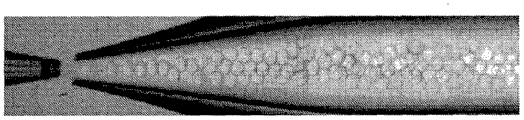
Although inner droplet fluid 250 is illustrated as in Fig. 2, form the continuous injection that extends to the exit opening 225 of pipeline 220 from pipeline 240, in some embodiments, inner droplet fluid 250 can arrive the one or more droplets of the front formation of exit opening 225.Under specific circumstances, can be in the rear further decomposition of the exit opening 225 that leaves pipeline 220 at the droplet of pipeline 220 interior generations.In some embodiments, can select like this flow velocity of inner droplet fluid 250 and/or outside droplet fluid 260 and/or intrasystem other parameters (such as fluid viscosity, channel size, conduit wall character etc.), thereby make to occur in the jet of the inside droplet fluid 250 in outside droplet fluid 260 in pipeline 220.As used herein, " jet " scheme refers to the wherein situation of the Continuous Flow Continuous Flow by the second fluid extending longitudinally of the first fluid (for example inner droplet fluid 250), does not contain and decompose to be formed on the internal flow droplet (although same fluid resolves into droplet generally in the outside generation of jet scheme) in external fluid in this scheme.In some embodiments, fluid in jet scheme (for example inside droplet fluid 250 in Fig. 2) can be at the droplet cross-sectional diameter finally being formed by fluid at least about 5, at least about 10 or at least about the length of 25 times on be continuous, the exit opening of the pipeline of wherein sending by it from fluid is measured continuous length in its punishment solution to form the point of droplet to fluid.
By contrast, " drip " scheme refers to that wherein for example, the first fluid resolves into the situation of droplet in the second fluid within pipeline (pipeline in Fig. 2 240) outlet of sending by it with it is less than or equal to the distance of approximately 2 times of average cross-sectional diameter of the first droplets of fluid of formation.As a specific examples, in the embodiment group shown in Fig. 2, inner droplet fluid 250 is illustrated as from pipeline 240 and flows in jet scheme, and inner droplet fluid 250 and outside droplet fluid 260 are illustrated as from pipeline 220 and flow in trickle flow regime.
In some embodiments, inner droplet fluid 250 and outside droplet fluid 260 do not decompose to form droplet, until fluid (, to end 235 right sides, this limits the inlet aperture of the pipeline 230 in Fig. 2) when pipeline 230 is interior.Yet in other embodiments, inner droplet fluid 250 and outside droplet fluid 260 before entering pipeline 230 (that is, to end 235 left sides) decompose to form droplet.Under " drippage " condition, droplet forms closer to the aperture at end 235 places of pipeline 230, and under " injection " condition, droplet, in further downstream formation, moves right as shown in Figure 2 again.For example, under specific " drippage " condition, in the time of in being placed in single hole diameter, produce droplet; This operator scheme can be similar to the tap dripping.Under some injection conditions, be created in the long injection of extending three or more hole diameters along collecting pipe length downstream, wherein discharge decomposition becomes droplet.
In a plurality of embodiments of the present invention, droplet forms and form (and/or corresponding form of the particle being formed by droplet) can be affected in many ways.For example, device 200 geometry (physical configuration) comprises that the relation of external pipe and internal pipeline can be configured to the multiple emulsion that development has volume required, frequency and/or content.For example, at the exit opening 225 of pipeline 220 and 240 and/or the exit opening diameter at 245 places, can be chosen as the relative volume that helps to control the droplet that forms respectively.In some cases, droplet forms and can be subject to following impact: the variation in the flow velocity of the flow velocity of inner droplet fluid, outside droplet fluid, the flow velocity that carries fluid, the total amount that flows or the ratio of any two in these and/or any combination in these flow velocitys.
In specific embodiments, can also control carefully the relative volume of inner droplet and outside droplet, i.e. the size of inside and outside droplet or the ratio of volume.Inner droplet can be filled relatively most outside droplet.This type of emulsion can for example be used to form the particle with relative shell, as discussed in this article.In some embodiments, inner droplet fluid can be filled the outside droplet volume that is greater than approximately 10%, approximately 20%, approximately 30%, approximately 40%, approximately 50%, approximately 60%, approximately 70%, approximately 90%, approximately 95% or approximately 99%.In some cases, when outside droplet contains inner droplet, its can be considered as flowing shell or coating, because some or most of outside droplet volume can be filled by inner droplet.In some embodiments, external fluid thickness of the shell can be equal to or less than for example approximately 5%, approximately 4%, approximately 3%, approximately 2%, approximately 1% or approximately 0.1% external fluid droplet radius.In some embodiments, this allow to form the multiple emulsion only with material layer as thin as a wafer, and described material layer is separated and therefore stablize two kinds of miscible fluids.
Certainly, the present invention is not limited to comprise the formation of the multiple emulsion of thin outside droplet, and in other embodiments, inner droplet can only be filled the outside droplet of fraction.In some embodiments, inner droplet can fill and be less than approximately 90%, is less than approximately 80%, is less than approximately 70%, is less than approximately 60%, is less than approximately 50%, is less than approximately 30%, is less than approximately 20% or be less than approximately 10% outside droplet volume.Shell material can also be more than or equal to for example approximately 10%, approximately 20%, approximately 30%, approximately 40% or approximately 50% external fluid droplet radius.
In addition, in specific embodiments, by controlling the geometry (physical configuration) of pipeline and/or the fluid by pipeline flows, can control the average cross-sectional diameter of the droplet of generation.For example use laser light scattering, microexamination or other known technologies, those of ordinary skills can measure the average cross-sectional diameter (or other characteristic sizes) of multiple or a series of droplets.The average cross-sectional diameter of the single droplet in non-spherical droplet is to have the diameter spherical with the ideal of non-spherical droplet same volume.In some cases, the average cross-sectional diameter of droplet (and/or multiple or a series of droplet) can for example be less than about 1mm, is less than approximately 500 microns, is less than approximately 200 microns, is less than approximately 100 microns, is less than approximately 75 microns, is less than approximately 50 microns, is less than approximately 25 microns, is less than approximately 10 microns or be less than approximately 5 microns.Under specific circumstances, average cross-sectional diameter can be also at least about 1 micron, at least about 2 microns, at least about 3 microns, at least about 5 microns, at least about 10 microns, at least about 15 microns or at least about 20 microns.In some embodiments, in multiple droplet at least about 50%, at least about 75%, at least about 90%, at least about 95% or at least about 99% droplet, there is the average cross-sectional diameter in any scope of summarizing in this paragraph.
Droplet can have substantially the same shape and/or size (i.e. " single dispersion "), or difformity and/or size, depends on application-specific.In some cases, droplet can have being uniformly distributed of cross-sectional diameter, be that droplet can have such cross-sectional diameter distribution, thereby make to be no more than approximately 10%, approximately 5%, approximately 3%, approximately 1%, approximately 0.03% or approximately 0.01% droplet, have such average diameter, it surpasses approximately 10%, approximately 5%, approximately 3%, approximately 1%, approximately 0.03% or approximately 0.01% different from the average cross-sectional diameter of droplet.More equally distributed technology for generation of droplet cross-sectional diameter are disclosed in international patent application no PCT/US2004/010903 and are incorporated to as described below and/or by reference in other lists of references herein, described international patent application is submitted on April 9th, 2004 by people such as Link, name is called " Formation and Control of Fluidic Species ", open as WO2004/091763 on October 28th, 2004, be incorporated to by reference herein.
In some cases, for example, when outside droplet (containing outside droplet fluid 260) forms with the speed identical with inner droplet (containing inner droplet fluid 250), between inner droplet number and outside droplet number, can there is man-to-man correspondence; For example in some embodiments, each inner droplet is surrounded by outside droplet, and each outside droplet single inner droplet of containing internal flow.In other embodiments, can there is the different proportion of inner droplet number and outside droplet number.In some embodiments, the multiple emulsion droplet of all generations is all dual emulsion droplet substantially.
In some embodiments of the present invention, multiple emulsion at least partly for example external fluid and/or internal flow can solidify, to form particle.Fluid can be used any suitable method to be cured.For example, in some embodiments, fluid can be dried, gelling and/or polymerization and/or otherwise solidify, for example, to form solid or at least semi-solid.In some embodiments, the solid of formation can be rigidity, although in other cases, solid can be flexible, rubberlike, variable etc.In some cases, for example external fluid can be solidified, the solid shell that comprises the inside of containing fluid and/or reagent to be formed to small part.Can use any technology that can be cured to small part droplets of fluid.For example, in some embodiments, can remove the fluid in droplets of fluid, to stay, can form the material (for example polymer) of solid shell.In other embodiments, droplets of fluid can be cooled to lower than the fluid fusing point in droplets of fluid or the temperature of glass transition temperature, can induce at least part of curing chemical reaction (such as polymerisation, produce reaction between two kinds of fluids of solid product etc.) causing droplets of fluid etc.Other examples comprise that pH responds or molecule can be identified polymer, for example the material of gelling after being exposed to specific pH or particular types.
In some embodiments, droplets of fluid is cured by increasing the temperature of droplets of fluid.For example, the rising in temperature can for example, be evicted material from from droplets of fluid (externally droplet fluid is interior), and leaves the another kind of material that forms solid.For example, in the embodiment shown in Fig. 2, fluid 260(and outside droplet 280 therefore) can contain the polymer being for example suspended in, in liquid (hydrophobic liquid).Liquid in fluid 260 can be removed by heating droplet from outside droplet 280, leaves encirclement droplet 285(and contains inner droplet fluid 250) curing polymerization shell.
Therefore, outside droplet can solidify to form the solid shell of one or more fluids of encapsulation and/or reagent, for example, for delivery to target medium, as other local descriptions herein.For example, in Fig. 2, below describe in detail with particle like the Particle Phase described in Figure 1A-1D can be by droplet 280 and fluid 250 hardening be formed.This type of particle can be for the reagent in fluid 250 is delivered to target medium, as other local descriptions herein.
In some embodiments, may wish to control the temperature of drying multiple emulsion droplet.For example, in some these type of embodiments that shell forms by drying multiple emulsion therein, control baking temperature and can guarantee that shell so configures, thereby it is not broken during dry run.In some embodiments, multiple emulsion can be dried at the temperature of approximately 25 ℃-Yue 100 ℃, approximately 40 ℃-Yue 80 ℃, approximately 50 ℃-Yue 70 ℃ or approximately 55 ℃-Yue 65 ℃.In some embodiments, multiple emulsion can be before dry (or in some cases, afterwards) using multiple suitable solvent to wash, described solvent includes but not limited to toluene and water.For example, in one group of embodiment, after particle forms, contain carrying fluid and can being removed and/or replacing with medium (for example, for delivery to target medium) of particle, described medium can be with to carry fluid identical or different.
Should be understood that Fig. 2 and associated description are only exemplary, and in a plurality of embodiments of the present invention, also considered other multiple emulsions (such as thering are the droplet of different numbers, nested level etc.) and other system.For example, the device in Fig. 2 can be configured to comprise other flow arrangement and/or other concentric tubes, for example, to produce more highly nested droplet.By supplying the fluid such as the 4th kind, the 5th kind, the 6th kind, can be created in the droplet becoming increasingly complex in droplet in specific embodiments.In particular of the present invention, some in these fluids can be identical (for example the first fluid can have the composition same with the third fluid-phase, and the second fluid can have the composition same with the 4th kind of fluid-phase etc.).
For example, Fig. 3 is included in the exemplary schematic diagram of the system 300 that wherein forms triple emulsions.In Fig. 3, system 300 comprises external pipe 310,320 and second internal pipelines of first internal pipeline (or ascending pipe) (or collecting pipe) 330.First internal pipeline 320 comprises exit opening 325, and it leads to external pipe 310, and second internal pipeline 330 is included in the entrance opening 335 of opening in external pipe 310.
As shown in Figure 3, with direction from left to right, flow through pipeline 320 and leave exit opening 325 and enter in pipeline 310 of internal flow 350.In addition, diagram fluid 360 is outside internal flow 350 and pipeline 320, with the pipeline 310 of flowing through of direction from left to right.Approach the entrance opening 335 of pipeline 330, fluid 360 surrounds fluids 350, nested to form first of triple emulsions.Diagram fluid 370 enters pipeline 310 and mobile with direction from right to left from right side.After contacting with fluid 360, fluid 370 reverse directions, and the entrance opening 335 that approaches pipeline 330 surrounds fluids 350 and 360, nested to form second of triple emulsions.Diagram fluid 380 enters pipeline 310 and mobile with direction from right to left from right side.Fluid 370 and 380 arranges like this, thereby makes fluid 370 form sheath, and fluid 380 forms the core that core-sheath flows and arranges.After arriving the entrance opening 335 of pipeline 330, fluid 380 changes directions and surrounds fluid 350,360 and 370, nested to form the 3rd of triple emulsions.
Fig. 4 is included in the exemplary schematic diagram of the system 400 that wherein forms quadruple emulsion.Pipeline arrangement in Fig. 4 is similar to the arrangement in Fig. 3, comprises external pipe 410,420 and second internal pipelines of first internal pipeline (or ascending pipe) (or collecting pipe) 430.First internal pipeline 420 comprises exit opening 425, and it leads to external pipe 410, and second internal pipeline 430 is included in the entrance opening 435 of opening in external pipe 410.
As shown in Figure 4, with direction from left to right, flow through pipeline 420 and leave exit opening 425 and enter in pipeline 410 of internal flow 450.In addition, diagram fluid 460 is outside internal flow 450 and pipeline 420, with the pipeline 410 of flowing through of direction from left to right.Diagram fluid 465, with the pipeline 410 of flowing through of direction from left to right, surrounds fluid 460 simultaneously.Diagram fluid 470 enters pipeline 410 and mobile with direction from right to left from right side.After contacting with fluid 465, fluid 470 reverse directions, and flow towards the entrance opening 435 of pipeline 430.Diagram fluid 480 enters pipeline 410 and mobile with direction from right to left from right side.Fluid 470 and 480 arranges like this, thereby makes fluid 470 form sheath, and fluid 480 forms the core that core-sheath flows and arranges.After arriving the entrance opening 435 of pipeline 430, fluid 480 changes direction.Approach the entrance opening 435 of pipeline 430, fluid 460 surrounds fluid 450, nested to form first; Fluid 465 surrounds fluid 450 and 460, nested to form second; Fluid 470 surrounds fluid 450,460 and 465; And fluid 480 surrounds fluids 450,460,465 and 570, nested to form the 4th of quadruple emulsion.
Comprise and surpass any in the character that two nested multiple emulsions (such as triple emulsion, quadruple emulsion etc.) can have other places description with regard to dual emulsion herein.For example, rate of flow of fluid can be controlled like this, thereby makes each nestedly comprise single droplet.In this type of embodiment, multiple emulsion comprises the nuclear fluid being surrounded by the multiple external fluid of multilayer.Each droplet in this type of multiple emulsion can have any in other local character of describing (such as the variation in thickness, thickness (or it lacks), cross-sectional diameter etc.) herein.For example, in the embodiment shown in Fig. 4, any in the shell being formed by fluid 460,465 and 470 in quadruple emulsion can have any in other local thickness of describing herein and/or the variation in thickness.As another example, the quadruple emulsion (or in other embodiments, comprising further nested) forming in Fig. 3 and 4 can have any in distributing of other local cross-sectional diameters of describing herein and/or cross-sectional diameter.
Although contain the multiple emulsion of single droplet in each nested level, described, be to be understood that the present invention is not so limited, and in some embodiments, one or more nested levels contain and surpass a kind of droplet.For example, in some embodiments, internal flow forms multiple droplet in central fluid, and central fluid surrounded by external fluid thin layer, described external fluid and then surround by carrying fluid.Some these type of embodiments are shown in Figure 13 C.In some embodiments, external fluid is surrounded central fluid, and described central fluid is surrounded multiple external fluid, and the multiple penetralia fluid that each leisure of described external fluid is carried in fluid forms thin layer of fluid around.By control, be used to form the relative velocity of the fluid of multiple emulsion, in any nested level of multiple emulsion, form multiple droplet.
Multiple droplet is present under the certain situation in given nested level therein, and for the given nested level of multiple emulsion droplet, the droplets of fluid of this level can contain the internal flow droplet of substantially the same number separately therein; For example, all droplets can contain the droplet of substantially the same number therein substantially.Even if be to be understood that droplet looks like (in any part of multiple emulsion droplet) being substantially equal to, or contain therein the droplet of substantially the same number, be not that all droplets must be equal to completely.Can there is less variation in number and/or the size of the droplet that in some cases, droplet contains around.Therefore, in some cases, multiple droplet at least about 75%, at least about 80%, at least about 85%, at least about 90%, at least about 92%, at least about 94%, at least about 95%, at least about 96%, at least about 97%, at least about 98% or at least about 99%, can contain therein separately the droplet of substantially the same number.
The productivity ratio of multiple emulsion droplet can determine by droplet forming frequency, and under many conditions, described droplet forming frequency can change between about 1Hz-5000Hz.In some cases, droplet productivity ratio can be at least about 1Hz, at least about 10Hz, at least about 100Hz, at least about 200Hz, at least about 300Hz, at least about 500Hz, at least about 750Hz, at least about 1,000Hz, at least about 2,000Hz, at least about 3,000Hz, at least about 4,000Hz or at least about 5,000Hz.
In some cases, the production of a large amount of emulsions can by multiple device for example those parallel use described herein be promoted.In some cases, can the relatively a large amount of device of parallel use, for example at least about 10 devices, at least about 30 devices, at least about 50 devices, at least about 75 devices, at least about 100 devices, at least about 200 devices, at least about 300 devices, at least about 500 devices, at least about 750 device or at least about 1,000 device or more can operation repetitive.Device can comprise different pipelines (such as concentric pipe), opening, microfluid etc.In some cases, the array of such device can form by level and/or vertical stacking apparatus.Depend on application, device can co-controlling, or separately controls, and can provide together with multiple fluid common or that separate source.
System and method described herein can be in multiple application.For example, wherein particle described herein and multiple emulsion can be that useful field includes but not limited to food, beverage, health & beauty auxiliary agent, coating and coating, Chemical Decomposition and medicine and drug delivery.For example, the exact magnitude of fluid, medicine, medicament or other reagent can be designed as the shell that discharges under given conditions its content and comprises.In some cases, cell can be included in droplet, and for example target medium in experimenter for example can be stored and/or be delivered to cell.Other reagent that can be included in particle and be delivered to target medium for example comprise for example for example siRNA, RNAi and DNA, protein, peptide or enzyme of nucleic acid of biochemistry kind.The other reagent that can be included in emulsion includes but not limited to colloidal solid, magnetic-particle, nano particle, quantum dot, spices, protein, indicator, dyestuff, fluorescence kind, chemicals etc.Target medium can be any suitable media, for example water, salt solution, aqueous medium, hydrophobic medium etc.
In one group of particular, can use multiple emulsion technology described herein to form the particle that comprises shell.In some embodiments, as non-limiting illustrative example, one or more particles can be for being delivered to target medium by fluid and/or reagent, for example hydrocarbon, crude oil, oil or other media.In some cases, at least some in particle can comprise solid portion or shell, and it comprises the inside of containing fluid and/or reagent at least partly.The shell of particle can comprise polymer, and in some cases, all polymer substantially in shell are solvable at least partly in target medium.The fluid that carries that forms therein particle can be as medium for making particle and target medium contact, and/or carry fluid and can be replaced by suitable medium thing, as other local descriptions herein.When particle contact target medium, can for example the destroying so at least partly of particle shell, thereby make intragranular fluid and/or reagent at least some be discharged from or from particle, be transported in target medium in addition.Certainly, be to be understood that particle can be equally for example, for other other application, as discussed in this article.
In some embodiments, particle of the present invention is configured to stand relatively high absolute pressure.
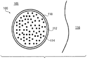
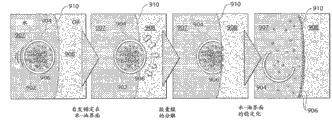
Figure 1A-1D is according to embodiments more of the present invention, particle 100 is shown fluid 112 and/or reagent 114 are delivered to target medium 116(such as the medium that contains oil such as crude oil, hydrocarbon etc.) the illustrative diagram of purposes.Particle 100 can for example be suspended in medium 105.In these figure, particle 100 comprises shell 110, and it partly or entirely surrounds fluid 112.As shown in this example, fluid 112 contains reagent 114, and although for example surfactant or as discussed in this article other reagent, in other cases, may not exist reagent.In some embodiments, shell 110 can partly or entirely surround any suitable material.Material can be such as solid or semisolid, reagent etc.In addition, in some cases, can exist and surpass a kind of material.
Medium 105 can comprise and is configured for any suitable fluid that particle 100 is delivered to target medium 116.(for example, in the situation that target medium 116 contains crude oil and/or other hydrocarbon therein) in some embodiments, medium 105 is hydrophilic (for example aqueous vehicles).
In some embodiments, the particle 100 comprising in medium 105 is exposed to medium 116(and for example contains oily medium), thereby for example, while making shell contact medium (medium in Figure 1A 116), shell 100 destroyed at least partly.For example, the polymer in shell 110 can be configured at oil for example, solvable at least partly in (crude oil), thereby makes to contact while containing oily medium 116 when shell 110, being dissolved at least partly in medium 116 of shell 110, thus cause the destruction in shell 110.Polymer is configuration like this, thereby makes as discussed in this article, replaces for example crude oil of (or adding) oil, and it is solvable at least partly in hydrocarbon etc.In some cases, can form hole (and in some cases growth), or due to destruction, shell 110 distortion etc. of can splitting, rupture, become.In some embodiments, for example, due to this destruction in shell 110, the fluid 112 being comprised by shell 110 and/or reagent 114 can be exposed at least partly and contain oily medium 116.
Figure 1B-1D comprises the indicative icon that shows example process, and the shell 110 of particle 100 is destroyed by described example process, causes particle 100 to discharge fluid 112 and/or the reagent 114 wherein containing.Yet, be to be understood that this discussion only as an example, and be not meant to the restricted description destroying into shell 110.In Figure 1B, the shell 110 of the particle 100 within medium 105 comprises contacts with medium 116.As shown in Fig. 1 C, after contact medium 116, the part 118 of shell 110 is dissolved.In some embodiments, after part 118 is dissolved, shell 110 is left in some or all transhipments of fluid 112 and/or reagent 114, to be exposed to medium 116, as shown in Figure 1 D.Transhipment can be such as by convection current, diffusion, infiltration, electric drift etc.In some embodiments, shell 110 for example, shrinks when its content (fluid 112 and/or reagent 114) discharges.For example, the shell 110 in Fig. 1 D is depicted as the shell 110 being less than in Fig. 1 C, to represent this type of contraction of shell 110.In addition, in specific embodiments, the content of shell 100 (for example fluid 112 and/or reagent 114) can targeted release in medium 116.For example, in Fig. 1 D, the direction that fluid 112 and/or reagent 114 are shown as with arrow 120 discharges from shell 110.
In some embodiments, some or all polymer in shell are for example configured to, in target medium (medium that contains crude oil, hydrocarbon, oil, wet goods) solvable at least partly.As used herein, material configuration is for when material is exposed to liquid medium under 25 ℃ and 1 atmospheric pressure, in liquid medium, be " soluble ", wherein liquid medium has the quality of at least 100 times of quality of materials, and material enters liquid medium like this, thereby make when balance, all material is included in liquid medium, and do not have the part of material to form macroscopic phase separately (for example as the solid of precipitation or the fluid being separated).Be to be understood that as used herein, " solubility " not necessarily requires soluble material on molecular level, to be dissolved in medium, for example in some cases, can when balance, form the meticulous suspension separating, dispersion, emulsion etc.In addition, when using filler test discussed above, some but when not all material is soluble in liquid medium, material configuration is " partly soluble ".Under specific circumstances, one or more polymer in shell can be configured to solvable at least partly in the chemicals of " indication " target medium under specific circumstances, and for example its medium that hits is the medium that cannot easily limit on forming.For example, in some embodiments, one or more polymer in shell can be configured in octane solvable at least partly, and described octane can be as the chemicals of indication crude oil.
In some embodiments, shell can comprise one or more materials, and it is configured in hydrophylic fluids such as water, alcohol etc. soluble.In some embodiments, material can comprise one or more polymer for example described herein those.In some embodiments, the use of this type of shell material in particle allows the fluid comprising in particle and/or reagent to be delivered to the medium that particle contacts with it, for example hydrocarbon, oil, wet goods.
In an example, the multiple particle that comprises water-insoluble shell and contain surfactant (or any other suitable fluid and/or reagent for example described herein those) is suspended in water or another kind of suitable medium.In this example, the particle suspension liquid transhipment in water or in addition contact contain or at least suspect and contain oily region or position, such as oil well, oil reservoir, oil vessel (such as bottle or bucket), chemical plant, oil plant etc.In this example, before contact oil, it is substantially complete that the water-insoluble shell of particle is configured to keep, and guarantees that surfactant keeps being included in particle.In some embodiments, once the shell joint of particle touches target medium, shell is for example dissolved in medium at least partly with regard to destroyed, thereby makes at least some in surfactant be exposed to medium.
As implied above, in some embodiments, shell can comprise polymer.The illustrative polymers that is suitable for using in shell is drawn together but is not limited to mixture and/or the copolymer of polystyrene (PS), PCL (PCL), polyisoprene (PIP), poly-(lactic acid), polyethylene, polypropylene, polyacrylonitrile, polyimides, polyamide and/or these and/or other polymer.
In some embodiments, polymer can comprise relatively linear polymer.Usually, linear polymer dissolves more quickly than highly cross-linked polymer, and in many application, is therefore useful especially.In some embodiments, linear polymer is not (that is, polymer comprises the carbon atom straight chain with the chemical bonding of other chains, although can there is side group) being substantially cross-linked.Although be to be understood that linear polymer can not be cross-linked, linear polymer each other physics is wound around.
In some embodiments, there is relatively high glass transition temperature (T all or part of can the comprising of particle shell
g) polymer.The polymer with high glass transition temperature more has resistance to breaking or destroying under high temperature and/or high pressure, and this can be so that it be suitable for specific high temperature application examples as the purposes of some enhanced oil recovery processes.Yet, in other application, can not use the polymer with lower glass transition temperature.In some embodiments, all polymer substantially in shell have at least about 85 ℃, at least about the glass transition temperatures of 100 ℃, approximately 85 ℃-Yue 250 ℃ or approximately 85 ℃-Yue 200 ℃.By for example using differential scanning calorimetry (DSC), those of ordinary skills can measure the glass transition temperature of the polymer using in shell.Usually, DSC is defined as glass transition temperature at its lower polymer substrate and from glassy state, becomes the temperature of rubbery state.Usually, the polymer that has a relatively long chain length has less chain mobility and relative higher intensity, toughness and glass transition temperature relatively.The illustrative polymers with relatively high glass transition temperature is drawn together but is not limited to mixture and/or the copolymer of polystyrene (PS), PCL (PCL) and polyisoprene (PIP) and/or these and/or other polymer.
According to embodiments more of the present invention, the molecular weight of the polymeric material using in particle shell can also be chosen as gives required physical property.For example, therein with after target medium contact, wish in the particular of the relative destruction of particle shell fast, can adopt to there is low weight mean molecule quantity and (be for example less than approximately 20, polymer 000g/mol).Wish therein relatively to break lentamente in some embodiments of shell, can adopt and there is relatively high weight average molecular weight (be for example greater than approximately 20,000g/mol, for example approximately 20,000g/mol – approximately 800, polymer 000g/mol).
In some embodiments, the shell of material is configured to stand applying of relatively high pressure and does not break.Mechanically strong shell can be by being produced by mechanical resistance material structure shell, and described mechanical resistance material is mechanically polymer or the other materials of resistance of polystyrene, PCL, polyisoprene and/or other for example.In some embodiments, can one or more particles (for example, dry rear) be implemented at least about 200kPa, at least about 500kPa, for example, at least about the absolute pressure (, particle is suspended in the water or the embodiment in another kind of medium of supercharging for delivery to oil reservoir therein) of 750kPa, the about 1000kPa of about 100kPa-or the about 750kPa of about 200kPa-, do not broken.In some embodiments, comprise some embodiments of wherein wishing high pressure resistance, the material using in shell is relative resilient.For example, in some embodiments, the Young's modulus of the polymeric material using in shell can be at least about 1MPa, at least about 10MPa, at least about 100MPa or at least about 1GPa.The Young's modulus of the polymeric material using in shell in some embodiments, can be to be less than about 10GPa, to be less than about 5GPa or to be less than about 3GPa.
Particle can be configured to send plurality of reagents.Reagent can be fluid or solid, and/or reagent can be included in fluid (such as dissolving, suspension etc.).In some embodiments, for example, reagent can comprise one or more surfactants.Surfactant can for example be delivered to and contain oily medium, or other media as discussed in this article.When surfactant is delivered to while containing oily medium, for example, surfactant is stablized oil-water interface, and this prevents that oil from forming meticulous emulsion in water, thereby it is separated with water that oil is easier to.Kinds of surface activating agent can be included in particle.In some embodiments, for example, particle can contain ionic (for example cationic or anionic) surfactant.The exemplary anionic surfactant of fit for service includes but not limited to lauryl sodium sulfate (SDS), Texapon Special, NaLS, sodium laureth sulfate, dioctyl sodium sulfosuccinate, PFOS ester (PFOS), perfluorinated butane sulphonic acid ester, alkylaryl ether phosphate, alkyl ether phosphate, alkyl carboxylic acid ester, soap (soap), odium stearate, sodium lauroyl sarcosine, carboxylate fluorine surfactant, perfluoro-pelargonic acid ester, per-fluoro octanoate (PFOA or PFO) etc.Fit for service exemplary male ionic surfactant includes but not limited to cetrimonium bromide (CTAB), softex kw, cetyltrimethylammonium chloride (CTAC), Cetylpyridinium Chloride (CPC), polyethoxylated tallow amine (POEA), benzalkonium chloride (BAC), benzethonium chloride (BZT) etc.In some embodiments, use nonionic surface active agent, include but not limited to: Arlacel-80 (also referred to as Span80); PEG-block-poly-(propane diols)-block-PEG, poly-(propane diols)-block-PEG-block-poly-(propane diols) (also referred to as F108); Polyvinyl alcohol (PVA); Cetanol, stearyl alcohol; Cetostearyl alcohol (for example mainly being formed by cetanol and stearyl alcohol); Oleyl alcohol; Polyoxyethylene glycol alkyl ether (Brij); Eight glycol monododecyl ethers; Five glycol monododecyl ethers; Polyoxypropylene diols alkyl ether; Glucoside alkyl ether; Plantacare 818; Lauryl glucoside; Octyl glucoside; Polyoxyethylene glycol octylphenol ether; Triton X-100; Polyoxyethylene glycol alkyl phenol ether; Nonoxynol-9; Glycerine Arrcostab; Glyceryl laurate ester; Polyoxyethylene glycol sorbitan Arrcostab; Polysorbate; Sorbitan Arrcostab; Coconut oleoyl amine MEA; Coconut oleoyl amine DEA; DDAO; The block copolymer of polyethylene glycol and polypropylene glycol; Poloxamer; Etc..
In some embodiments, the use of ionic surfactant is favourable because for example therein particle be suspended in for example, application in saltwater environment (seawater) or other suitable medium things, shell can be more stable.Do not wish to be bound to any particular theory, think and in salt solution, use ionic surfactant that the osmotic equilibrium between the fluid outside shell-side fluid (or other guide thing) and shell is provided, and this osmotic equilibrium helps to stablize shell.
Particle can be suspended in any suitable medium (for example medium in Figure 1A-1D 105).In some embodiments, to be suspended in medium be wherein hydrophilic to particle.In an example, medium 105 comprises seawater, and it can be for example for being extremely discharged into particle delivery through the country and/or being positioned at crude oil or other hydrocarbon of the subsurface oil storage in sea.Suitable hydrophilic vectorial example includes but not limited to water, alcohol (for example butanols (for example n-butanol), isopropyl alcohol (IPA), propyl alcohol (for example normal propyl alcohol), ethanol, methyl alcohol, glycerine etc.), saline solution, blood, acid (for example formic acid, acetic acid etc.), amine (for example dimethylamine, diethylamine etc.), these mixture and/or other phase quasi-fluids.In some embodiments, polar aprotic solvent (such as alcohol, acid, alkali etc.) can be in hydrophilic medium.In some embodiments, polar non-solute can, in hydrophilic medium, comprise for example dimethyl sulfoxide (DMSO) (DMSO), acetonitrile (MeCN), dimethyl formamide (DMF), acetone etc.Be to be understood that the present invention is not limited to hydrophilic medium, and in other embodiments, can use hydrophobic medium.
Particle described herein can have any suitable average cross-sectional diameter.For example use laser light scattering, microexamination or other known technologies, those of ordinary skills can measure the average cross-sectional diameter of single particle and/or multiple particle.In aspherical particle, the average cross-sectional diameter of single particle is to have the diameter spherical with the ideal of aspherical particle same volume.In some cases, the average cross-sectional diameter of particle (and/or multiple or a series of particle) can for example be less than about 1mm, be less than approximately 500 microns, be less than approximately 200 microns, be less than approximately 100 microns, be less than approximately 75 microns, be less than approximately 50 microns, be less than approximately 25 microns, be less than approximately 10 microns or be less than approximately 5 microns, or approximately 50 microns-Yue 1mm, approximately 10 microns-Yue 500 microns or approximately 50 microns-Yue 100 microns.Under specific circumstances, average cross-sectional diameter can be also at least about 1 micron, at least about 2 microns, at least about 3 microns, at least about 5 microns, at least about 10 microns, at least about 15 microns or at least about 20 microns.In some embodiments, multiple intragranular at least about 50%, at least about 75%, at least about 90%, at least about 95% or there is the average cross-sectional diameter in any scope of summarizing in this paragraph at least about 99% particle.
In some embodiments, the shell of one or more particles is relative thin.The use of shell can provide many advantages.For example, in some cases, shell can dissolve relatively rapidly.In some embodiments, this can allow particle to send its content before being transported away from target medium.Another advantage that use has the particle of shell is dry with during forming the process of particle shell by it at the outside liquid of droplets of fluid, wherein outside liquid contains the polymer solidifying with formation shell, at least according to particular, the removal of liquid can relatively easily be carried out, and the shell that does not break and form.In some embodiments, when adopting relatively thick shell, shell is tending towards breaking when liquid is wherein removed at polymer suspension.Do not wish to be bound to any particular theory, for example think, when adopting relatively thick shell (having the shell that is greater than approximately 10 micron thickness), the outermost of shell part can be drier more quickly than the inside part of shell, and generation can be broken or be destroyed in addition the pressure of shell.Do not wish to be bound by any theory, think and use the centre with very narrow thickness to allow mutually centre to serve as mutually lubricant, thereby make fluid in lubricating status.In this state, to the drag force of penetralia fluid, be significantly to increase.Increase in drag force is considered to strengthen the stability of shell fluid.The migration velocity of the inner droplet of 98 micron diameters for example, being surrounded by 100 microns of shells is lower 100,000 times than the migration velocity of the inner droplet of 50 micron diameters being surrounded by 100 microns of shells.
In some embodiments, the shell of particle has than particle average cross-sectional diameter and is less than approximately 0.05, is less than approximately 0.01, is less than approximately 0.005 or be less than approximately 0.001 times, or the average thickness (averaging on whole particle) of approximately 0.001 times of the about 0.0005-of particle average cross-sectional diameter approximately 0.05, about 0.0005-approximately 0.01, about 0.0005-approximately 0.005 or about 0.0005-.In some embodiments, the shell of particle has and is less than approximately 1 micron, is less than about 500nm or is less than about 100nm, or the average thickness of approximately 1 micron of about 50nm-, the about 500nm of about 50nm-or the about 100nm of about 50nm-.In some embodiments, multiple intragranular at least about 50%, at least about 75%, at least about 90%, at least about 95% or comprise the shell with the average thickness in any scope of summarizing in this paragraph at least about 99% particle.By for example checking SEM (SEM) image of particle, those of ordinary skills can measure the average thickness of shell.
For many application, may wish multiple particle delivery to target medium, at least some in described particle contain for example surfactant of fluid and/or reagent.In order to ensure predictable reagent, send, some embodiments advantageously adopt the particle with relative uniformity matter.For example, in some embodiments, provide multiple particle, wherein the distribution of the thickness of the shell in multiple particle is relatively uniform.In some cases, there is the use of the particle of thickness of the shell relatively uniformly and can guarantee consistent shell dissolution time, reagent is sent more measurable.In some embodiments, provide as the measurement of average value of multiple particle average thickness of the shell separately, there is the multiple particle of population mean thickness of the shell.In some cases, the distribution of average thickness of the shell can be such, thus make to be no more than approximately 5%, be no more than approximately 2% or be no more than approximately 1% particle and have than the thin 90%(of population mean thickness of the shell or thin 95% or thin 99%) and/or than the thick 110%(of population mean thickness of the shell or thick 105% or thick approximately 101%) the shell of average thickness of the shell.
In specific embodiments, multiple particle can have cross-sectional diameter relatively uniformly.There is relatively the viscosity that the use of the particle of cross-sectional diameter uniformly can allow to control particle suspension liquid, the amount of reagent that is delivered to target medium and/or by other parameters of particle delivery fluid and/or reagent.In some embodiments, multiple particle has such population mean diameter and diameter and distributes, thus make to be no more than approximately 5%, be no more than approximately 2% or be no more than approximately 1% particle have be less than about 90%(be less than approximately 95% or be less than approximately 99%) diameter and/or be greater than about 110%(or be greater than approximately 105% or be greater than approximately 101%) diameter of the population mean diameter of multiple particle.
In some embodiments, multiple particle has such population mean diameter and diameter and distributes, thereby makes the coefficient of variation of particle cross-sectional diameter be less than approximately 10%, is less than approximately 5%, is less than approximately 2%, about 1%-approximately 10%, about 1%-approximately 5% or about 1%-approximately 2%.The coefficient of variation can be measured by those of ordinary skills, and can be defined as:
Wherein σ is standard deviation, and μ is mean value.
As used herein, when at its lower temperature and condition that produces emulsion, when a kind of fluid is not dissolved to by weight at least 10% level in another kind, two kinds of fluids are not miscible or immiscible each other.For example, can be chosen as in the time frame forming in droplets of fluid be not miscible for two kinds of fluids.In some embodiments, two kinds of fluids (for example multiple emulsion carry fluid and inner droplet fluid) are compatible or miscible, and outside droplet fluid is inconsistent or immiscible with carrying with one of inner droplet fluid or both.Yet in other embodiments, all three kinds of (or more kinds of) fluids can be mutually not miscible, and under specific circumstances, all fluids differ, and to establish a capital must be water miscible.In other other embodiments, as mention, can add the fluid such as other the 4th kind, the 5th kind, the 6th kind, to produce the droplet becoming increasingly complex in droplet, for example carry fluid and can surround the first fluid, described the first fluid and then can surround the second fluid, described the second fluid and then can surround the third fluid, described the third fluid and then surround the 4th kind of fluid etc.In addition, for example, by controlling the composition of each nested level, can control independently of one another the physical property of each nesting level of droplets of fluid.
As used herein, term " fluid " refers generally to the material that is tending towards mobile and meets its container profile, i.e. liquid, gas, viscoelastic fluid etc.Usually, fluid is the material that is not able to take static shear stress, and when applying shear stress, fluid experience continues and lasting distortion.Fluid can have any appropriate viscosity that permission is flowed.If there are two or more fluids, by considering the relation between fluid, every kind of fluid can be by those of ordinary skills independently selected from any fluid (liquid, gas etc.) substantially.
In one aspect of the invention, as discussed, multiple emulsion can be by forming fluid one or more pipelines of flowing through.This system can be microfluid system.As used herein, " microfluid " refers to comprise device, instrument or the system of at least one fluid passage, described fluid passage has the cross sectional dimensions that is less than approximately 1 millimeter (mm), and in some cases, at least the length of 3:1 and cross-sectional dimension ratio.One or more pipelines of system can be capillaries.In some cases, provide a plurality of pipelines, and in some embodiments, as described herein, at least some are nested.Pipeline can be in microfluid magnitude range, and can have and for example be less than approximately 1 millimeter, be less than approximately 300 microns, be less than approximately 100 microns, be less than approximately 30 microns, be less than approximately 10 microns, be less than approximately 3 microns or be less than the mean inside diameter of approximately 1 micron or there is the part of internal diameter, thereby provide, there is the droplet that can compare average diameter.Ducted one or morely can have (but not necessarily) height substantially the same with width on identical point in cross section.Pipeline can comprise opening, and it can have the size less, larger or more identical than the average diameter of pipeline.For example, pipeline tapping can have and is less than about 1mm, is less than approximately 500 microns, is less than approximately 300 microns, is less than approximately 200 microns, is less than approximately 100 microns, is less than approximately 50 microns, is less than approximately 30 microns, is less than approximately 20 microns, is less than approximately 10 microns, is less than the diameter of approximately 3 microns etc.In cross section, pipeline can be rectangle or non-rectangle substantially, for example circular or oval-shaped.Pipeline of the present invention can also be arranged or be nested in another pipeline, and in some cases, multinest is possible.In some embodiments, a pipeline can be retained in another pipeline with one heart, and two pipelines are considered as concentric.Yet concentric pipe can depart from center with regard to another places, and surrounds pipeline, i.e. " concentric " strict coaxial pipe of definiteness that differs.By using concentric or nested geometry, mixable two kinds of fluids can be avoided contact.
In some embodiments, fluid, pipeline (comprising duct wall) and other materials can be called as hydrophobic or hydrophilic.When being placed in discussed material intimate contact in air at 1 atmospheric pressure and 25 ℃, when water droplet forms the contact angle that is greater than 90 °, material is " hydrophobic ".When being placed in discussed material intimate contact in air at 1 atmospheric pressure and 25 ℃, when water droplet forms the contact angle that is less than 90 °, material is " hydrophilic "." contact angle " in the disconnected context of hydrophobicity and hydrophily be and the material surface at the contact point place of material surface and and the tangent line of water droplet outer surface between the angle measured, and measure by water droplet.Fig. 5 is the indicative icon of the contact angle 591 that forms on water wetted material 593 by water droplet 592 in air 597.As shown in Figure 5, contact point 596 places between droplet 592 and material surface 594, measure contact angle 591 from the surface 594 of the material 593 by droplet 592 to the tangent line 595 of the outer surface with droplet 592.
Multiple material according to a particular aspect of the invention and method can be used to form the material (for example above-described those) that is configured to produce multiple emulsion described herein and/or particle.In some cases, the multiple material of selection is suitable for several different methods.For example, a plurality of parts of the present invention are configured by solid material, and wherein via micromachined, film deposition process, for example rotary coating and chemical vapour deposition (CVD), laser structure, photoetching technique, etching method comprise that wet-chemical goods or plasma process etc. are configured to pipeline.Referring to for example Scientific American, 248:44-55, the people such as 1983(Angell).In one embodiment, fluid system is formed by silicon by etched parts in silicon chip at least partly.Technology for and effective structure of the present invention multiple fluid system and device accurate by silicon is known.In another embodiment, a plurality of parts of system of the present invention and device are configured by polymer, described polymer for example elasticity polymer for example dimethyl silicone polymer (" PDMS "), polytetrafluoroethylene (PTFE) (" PTFE " or
) etc.
Different parts can be constructed by different materials.For example, comprise diapire and sidewall base part can by opaque material for example silicon or PDMS construct, and top section can by transparent or at least partly transparent material for example glass or transparent polymer construct, for observing and/or control flow liquid process.Parts can be coated with like this, to make required chemical functional be exposed to the fluid of contact internal pipeline wall, wherein substrate support material does not have accurate desired function.For example, parts can as directedly be constructed, and wherein internal pipeline wall is coated with by another kind of material.For constructing the material of a plurality of parts of system of the present invention and device, for example for being coated with the material of fluid line inwall, can hopefully be selected from such material, its fluid that can not adversely affect the fluid of the fluid system of flowing through or the fluid system of being flowed through affects, for example chemically inert one or more materials under the existence of the fluid for the treatment of to use in device.The non-limitative example of this type coating is below open; Example is disclosed in international patent application serial number PCT/US2009/000850 in addition, described international patent application is submitted on February 11st, 2009 by people such as Weitz, name is called " Surfaces; Including Microfluidic Channels; With Controlled Wetting Properties ", open as WO2009/120254 on October 1st, 2009, be incorporated to by reference herein.
In some embodiments, a plurality of parts of the present invention are constructed by polymerization and/or elasticity and/or elastomeric material, and can, easily by forming by stiffening fluid, promote via the moulding structure of (such as copying moulding, injection moulding, cast molding etc.).Can stiffening fluid can be following any fluid substantially, it can be induced to solidify, or the spontaneous solid that can comprise and/or transport fluid that is solidified into, and described fluid is considered for using in fluid network and together with fluid network.In some embodiments, can comprise polymeric liquid or liquid polymeric precursor (that is, " prepolymer ") by stiffening fluid.Suitable polymeric liquid comprises that for example thermoplastic polymer, thermosetting polymer or heating surpass the mixture of this base polymer of its fusing point.As another example, suitable polymeric liquid can be included in one or more polymer solutions in suitable solvent, and described solution forms solid polymeric material after for example by evaporative removal solvent.Can by for example molten state or by solvent, to evaporate this type of polymeric material solidifying be that those of ordinary skills are well-known.Wherein many is that elastomeric multiple polymeric material is suitable, and for one or two embodiment being comprised of elastomeric material in mould mother matrix (mold master) wherein, is also suitable for forming mould or mould mother matrix.The non-limiting list of the example of this base polymer comprises the polymer of the general classes of silicone polymer, epoxy polymer and acrylate polymer.Epoxy polymer is characterised in that and is commonly called epoxy radicals, 1, the existence of the three membered cyclic ether of 2-epoxides or oxirane.For example, except the compound based on aromatic amine, triazine and cycloaliphatic main chain, can also use the diglycidyl ether of bisphenol-A.Another example comprises well-known Novolac polymer.The non-limitative example that is suitable for silicone elastomer used according to the invention comprises by precursor and comprises those that chlorosilane such as methylchlorosilane, ethyl chlorosilane, phenyl chlorosilane etc. form.
Use in some embodiments silicone polymer, for example silicone elastomer dimethyl silicone polymer.The non-limitative example of PDMS polymer is included under trade mark Sylgard by Dow Chemical Co., Midland, those that MI sells, and particularly Sylgard182, Sylgard184 and Sylgard186.Silicone polymer comprises that PDMS has the several favourable character of the structure of simplifying microfluidic structures of the present invention.For example, this type of material be cheap, can easily obtain, and can be via being heating and curing by pre-polymerization liquid curing.For example, by making pre-polymerization liquid exposure in temperature open-assembly time of approximately one hour for example of approximately 65 ℃-Yue 75 ℃ approximately for example, PDMS is generally curable.Therefore in addition, silicone polymer for example PDMS can be elastomeric, and can be used to form in particular of the present invention essentially, has the subminiature of relatively high length-width ratio.Elasticity (for example elastomer) mould or mother matrix can be favourable in this.
By silicone polymer for example PDMS form structure example as the advantage of microfluidic structures of the present invention be this base polymer for example by being exposed to containing the oxygen plasma oxidized ability of air plasma for example, thereby make oxidation structure contain in its surface can be crosslinked with the oxidized surface of other silica ketone polymers surfaces or multiple other polymerizations and non-cohesive material chemical group.Therefore, can structural member and with rear oxidation and be substantially irreversibly sealed to other silicone polymer surfaces, or with the surface of other matrix of silica ketone polymer surface reaction, and do not need separately to adhere to or other encapsulating methods.In most of the cases, sealing can be only by making to be oxidized silicone surface and another Surface Contact completes, and without applying aux. pressure to form sealing.That is, the silicone surface of pre-oxidation is served as the contact adhesive for suitable mating face.Particularly, can be to self seal except irreversibly, oxidation silicone is for example oxidized PDMS and can also be irreversibly sealed with a series of oxidation materials except self, described oxidation material comprises for example glass, silicon, silica, quartz, silicon nitride, polyethylene, polystyrene, vitreous carbon and epoxy polymer, and it is oxidized (for example, via being exposed to containing oxygen plasma) in the mode similar to PDMS surface.Useful oxidation and encapsulating method and overall forming technique are described in the art in the context of the present invention, for example be incorporated to by reference herein name is called " Rapid Prototyping of Microfluidic Systems and Polydimethylsiloxane; " Anal.Chem., 70:474-480, people such as 1998(Duffy) in paper.
In some embodiments, certain microfluidic body structure of the present invention (or inner, fluid contact surfaces) can be formed by the silicone polymer of specific oxidation.This type of surface can be more hydrophilic than elastomer polymer surface.Therefore this type of hydrophilic pipe surface can more easily be full of the aqueous solution or moistening by the aqueous solution.
In some embodiments, the diapire of microfluidic device of the present invention is formed by the material that is different from one or more sidewalls or roof or miscellaneous part.For example, in some embodiments, the surface that the inner surface of diapire comprises silicon wafer or microchip or other matrix.As mentioned above, miscellaneous part can be to this type of alternative matrix sealing.For example, when hope contains the parts of silicone polymer (PDMS) to the substrate of different materials (diapire) sealed packet, substrate can be selected from silica ketone polymer can for example, to the material group of its irreversible sealing (already oxidised glass, silicon, silica, quartz, silicon nitride, polyethylene, polystyrene, epoxy polymer and vitreous carbon surface).Alternatively, as apparent for those of ordinary skills, can use other Sealing Technologies, include but not limited to the use of separated adhesive, bonding, solvent bonding, ultrasonic bonding etc.
Following file for all objects by reference integral body integrate with herein: by people such as Link, on April 9th, 2004, submit to, name is called the International Patent Publication No. WO 2004/091763 of " Formation and Control of Fluidic Species "; By people such as Stone, on June 3rd, 2003, submit to, name is called the International Patent Publication No. WO 2004/002627 of " Method and Apparatus for Fluid Dispersion "; By people such as Weitz, on March 3rd, 2006, submit to, name is called the International Patent Publication No. WO 2006/096571 of " Method and Apparatus for Forming Multiple Emulsions "; By people such as Link, on August 27th, 2004, submit to, name is called the International Patent Publication No. WO 2005/021151 of " Electronic Control of Fluidic Species "; By people such as Chu, on March 28th, 2008, submit to, name is called the International Patent Publication No. WO 2008/121342 of " Emulsions and Techniques for Formation "; By people such as Weitz, on March 12nd, 2010, submit to, name is called the International Patent Publication No. WO 2010/104604 of " Method for the Controlled Creation of Emulsions, Including Multiple Emulsions "; By people such as Weitz, on September 1st, 2010, submit to, name is called the International Patent Publication No. WO 2011/028760 of " Multiple Emulsions Created Using Junctions "; By people such as Weitz, on September 1st, 2010, submit to, name is called the International Patent Publication No. WO 2011/028764 of " Multiple Emulsions Created Using Jetting and Other Techniques "; With by people such as Abbaspourrad, on July 6th, 2011, submit to, name is called the U.S. Provisional Patent Application of " Delivery to Hydrocarbons or Oil, Including Crude Oil ".Also the whole by reference people such as Abbaspourrad that pass through that integrate with this paper submitted on July 6th, 2011, name is called the U.S. Provisional Patent Application sequence number 61/505 of " Delivery to Hydrocarbons or Oil; Including Crude Oil ", 001, with by people such as Kim, on July 6th, 2011, submit to, name is called the U.S. Provisional Patent Application sequence number 61/504,990 of " Multiple Emulsions and Techniques for the Formation of Multiple Emulsions ".
Every other patent, patent application and the file of quoting herein also in this case all objects by reference integral body integrate with.
Following embodiment is intended to illustrate particular of the present invention, but illustration four corner of the present invention not.
Embodiment 1
This embodiment has described use micro-fluidic technologies, and preparation comprises the method for the relatively monodispersed dual emulsion droplet of thin central fluid layer.Two not miscible streams that limit in microfluidic channel can form stable injection or droplet under specific physical condition, and stream together emulsification to form dual emulsion droplet, as discussed in this article.Resulting dual emulsion droplet has the thin skin of the stability that can strengthen dual emulsion.System and method described in this embodiment can be applied to any thickness organic solvent, and in some embodiments, can promote to use a small amount of shell material preparation to have the particle of the shell that contains material.In addition, at least in some cases, the system and method described in this embodiment can produce the multiple emulsion of dual emulsion or higher level in single step.In some cases, for example, by evaporation foreign minister's (toluene), for example, to leave the polymer (poly-(lactic acid)) solidifying to form shell, can form and there is the relatively monodispersed particle that is less than 100nm thickness of the shell.
Two kinds of not miscible fluids of the single microfluidic channel of flowing through can show different unique flow pattern of droplet and injection, depend on several physical parameters.There is the more fluid of high-affinity with the wall of microfluidic channel and can form continuous phase, and there is the more fluid of low-affinity, can flow with the form of droplet or injection, and the wall of contact channels not.In many cases, flow and can produce the unsettled injection due to Rayleigh plateau (Rayleigh-Plateau) unstability, this causes discharge decomposition to become droplet separately; Yet the spatial limitation at interface can be for generation of more stable injection.When interface forms close to conduit wall, in some cases, unstability can reduce.
In some experiments in this embodiment, the emulsification of spraying by the stable two-phase entering in continuous phase produces dual emulsion droplet.In order to prepare the dual emulsion droplet of W/O/W (W/O/W), adopt microfluidic device.Fig. 6 A comprises the indicative icon for the preparation of the microfluidic device of dual emulsion droplet.Microfluidic device used herein comprises the hydrophobicity taper injection channel 610 of inserting in second square passageway 612, and the inside dimension of described second square passageway 612 is slightly larger than the external diameter of injection channel 610, as shown in Fig. 6 A.The square passageway by use with the internal diameter that is slightly larger than injection channel external diameter, two passages closely cooperate, the easier channel alignment of this pipe in can permission system.(although use square passageway herein, can also use the passage with other shapes).For two kinds of not miscible fluids (" oil " phase 602 and " water " phase 604) are flow in single injection channel, passage 614 is inserted in injection channels 610.In addition, collecting pipe 616 is inserted in square passageway, to limit access to, inject most advanced and sophisticated flowing, thereby increase flowing velocity and collect the droplet being produced by injection channel 610.In order to produce the dual emulsion droplet of W/O/W, n-octadecane base trimethoxy silane (Aldrich) is applied to and is injected on capillary wall, to cause it hydrophobic, and by 2-[methoxyl group (polyethyleneoxy) propyl group] trimethoxy silane (Gelest, Inc.) be applied to and collect on capillary wall, to cause it hydrophilic.)
In these experiments, make the PEG (PEG with 1 % by weight SPAN80 of 25 % by weight, MW6000) and the hexadecane aqueous solution (" oil " mutually 602) through injection channel, to form the decentralized photo of droplet, and make poly-(vinyl alcohol) (PVA, MW13,000-23 of 10 % by weight, 000) aqueous solution (" water " phase 606) is through passage 612, to form continuous phase.Should be understood that " oil " is advantageously used in mutually referring in water or " water " phase (it is miscible in water) not miscible phase substantially herein." oil " should not be construed as mutually and is only limited to oil, but can be included in water not miscible any fluid substantially.
The internal diameter that depends on the injection channel of using in microfluidic device, observes different resulting flow patterns.For example, in having the injection channel of 580 microns of internal diameters, the multiple water droplet of observing broad range flow velocity forms.As concrete non-limitative example, when the ratio of the volume flow rate of inner fluid streams and the volume flow rate of external fluid is made as 4:1, observes " a succession of " plug shape or extend droplet, as shown in the optical microscope image in Fig. 6 B; These microemulsifications become continuous fluid stream in the same way, to flow identical direction with inside and outside fluid, along injecting outer surface capillaceous, flow.When filling in the opening at shape droplet process channel end place, generate the outer field relatively monodispersed dual emulsion droplet with relative thin, and generate large oily (hexadecane) droplet for oil mobile between water droplet.The discontinuous generation of dual emulsion droplet is shown in the optical microscope image in Fig. 6 C.
As another non-limitative example, when use has the injection channel of 200 microns of internal diameters, under these specified conditions, form and stablize water injection, as shown in the optical microscope image in Fig. 6 D.This spray in a continuous manner the opening part of collecting pipe or near emulsification, cause monodispersed dual emulsion droplet.The use with less internal diameter passage provides the higher restriction at interface under these conditions, thereby reduces disturbance and produce stable injection.As visible in Fig. 6 C and 6E, the outer layer thickness of resulting dual emulsion droplet is too thin, and can not use light microscope Measurement accuracy.
Enter the flow pattern in the flow rate effect injection channel of stream, and therefore affect the generation of dual emulsion droplet.Fig. 7 A shows according to inner or " core " stream (fluid 604 in Fig. 6 A) and curve map outside or " coating " stream (fluid 602 in Fig. 6 A) flow velocity flow behavior in system, the multiple mobility program that indication is observed under different in flow rate separately, comprise wherein and to produce stable injection and/or the scheme of droplet, and wherein occur unsteady velocity and do not produce the scheme of droplet.For example, when the flow velocity of inside stream is enough high with respect to the given flow velocity of outer flow, in injection channel, forms and stablize water injection (ring-type), as shown in the top optical microscope image of Fig. 7 B.By contrast, when the flow velocity of inside stream reduces, spray and become unstable, and the fluctuation of display interface and do not decompose (triangle), as shown in the intermediate optical MIcrosope image of Fig. 7 B.The further minimizing of the flow velocity of inner stream obtains plug shape water droplet (cross), as shown in the bottom optical microscope image of Fig. 7 B.
Although the high flow rate of inner stream can produce stable injection, dual emulsion not necessarily generates by spraying.The high inertia flowing with the inside of high flow rate can cause that inner stream leaks in the continuous phase that approaches tip, injection channel, and this is corresponding to the region in Fig. 7 A (a).The value that the flow velocity of inside stream is made as in region (b) allows dual emulsion droplet to spray and the generation of drippage pattern.For example, for the internal reflux flows speed of approximately 1200 micro-ls/h, two-phase is sprayed the opening through collection channel end, and subsequently completely in collection channel, resolves into dual emulsion droplet, at spray tip place as shown in the optical microscope image of Fig. 7 C.By contrast, for the internal reflux flow speed of 800 micro-ls/h in this specific device, two-phase is injected in the opening emulsification that approaches collection channel in drippage pattern, as shown in the optical microscope image of Fig. 7 D.When the flow velocity flowing when inside is made as 400 micro-ls/h (or any other flow velocity in the region of Fig. 7 A (d)), observe the discontinuous generation of dual emulsion droplet, as shown in the optical microscope image of Fig. 7 E.For all experiments shown in Fig. 7 C-7E, the flow velocity of coating stream maintains 100 micro-ls/h.
The dual emulsion droplet of O/W/O can be prepared in a similar manner.In order to produce the dual emulsion droplet of O/W/O, by 2-[methoxyl group (polyethyleneoxy) propyl group] trimethoxy silane (Gelest, Inc.) be applied to and inject on capillary wall, to cause it hydrophilic, and n-octadecane base trimethoxy silane (Aldrich) is applied to and is collected on capillary wall, to cause it hydrophobic.Use has same geometry but the microfluidic device of opposed surface modification, prepares the dual emulsion droplet of the silicone oil of silicone oil (AR20)/1 % by weight F108 aqueous solution/2 % by weight DC749, as shown in Fig. 8 A-8C.Fig. 8 A is the indicative icon for the preparation of the microfluidic device of the dual emulsion droplet of O/W/O.Fig. 8 B-8C is presented at the optical microscope image that generates the dual emulsion droplet of O/W/O and the dual emulsion droplet of resulting single dispersion in drippage pattern.
When operating with drippage pattern, droplet generates and seems arranged by two competitiveness: make droplet remain on the capillary force of channel end and pull the downward drag force of droplet.For example, by controlling the flow velocity (this and drag force proportional) of continuous phase, can control the size of dual emulsion droplet.Fig. 9 A comprises according to the continuous fluid flow rate Q in external channel 612
3emulsion diametral curve figure, and Fig. 9 B shows the optical microscope image of the relatively monodispersed dual emulsion droplet prepare with flow velocity shown in continuous phase.When flow velocity increases, the diameter of dual emulsion droplet reduces, as shown in Fig. 9 A-9B.Resulting dual emulsion droplet is relatively monodispersed, and diameter has the coefficient of variation within the scope of 1.0-1.9%.
The outer layer thickness t of dual emulsion droplet is difficult to by optical microscope image Measurement accuracy.Yet outer field thickness can also be estimated by following: more dual emulsion droplet radius (R) drips radius (R with single " oil " prepared by the dual emulsion droplet that breaks
rup), described in break and make inside " water " transport and leave " oil " shell mutually, and enter continuously " water " mutually in, leave " oil " and drip." oil " thickness of the shell before breaking can be used following mass balance equation to calculate, and the volume (left side of equation 2) of noticing initial " oil " shell is by " oil " drop volume (right side of equation 2) that equals to form after the dual emulsion that breaks:
For example, two optical microscope image are shown in Fig. 9 D, and it demonstrates by mechanical force being put on to the dual emulsion droplet of dual emulsion suspension and breaks.Particularly, by the suspension of dual emulsion droplet is placed on glass slide, and for example on desktop, pat glass slide at the surface of solids, dual emulsion droplet breaks.The dual emulsion droplet that breaks causes single emulsion droplet (dashed circle in Fig. 9 D is indicated).The radius of observing in these two images is R=61 micron and R
rup=19 microns, cause the thickness of 620nm.
In the same manner, use at inside stream 604(Q
1) and outer flow 602(Q
2) multiple relative velocity under the multiple dual emulsion droplet that produces, calculate the outer layer thickness (referring to Fig. 9 C) of these dual emulsion droplets.In Fig. 9 C, top curve shows the external fluid thickness of the dual emulsion droplet of preparing by stable injection or drippage pattern, and the dual emulsion droplet of preparing from the discontinuous drippage of use in two data points of curve map bottom.Relevant to top curve and mass balance equation in Fig. 9 C of data fitting.Particularly, below equation 4 and 5 can be derived from the conservation of mass:
Wherein f drips generated frequency.By by equation 5 divided by equation 4 and reset, can obtain following equation:
By contrast, irrelevant with flow velocity, discontinuous drippage mode producing comprises the dual emulsion droplet of the external fluid layer with minimum relative thickness.Do not wish to be bound to any particular theory, this scheme can form consistent thin external fluid layer, because be placed in the amount (this finally forms the skin of dual emulsion droplet) of the oil phase between plug shape water droplet and injection channel inwall, is minimum.In fact, in this mobility program, the oil level that great majority inject, between plug shape water droplet, produces and is included in the relatively large plug cock between water droplet, the final core that forms dual emulsion droplet of described water droplet.Because few oil is placed in contiguous water droplet, so oil seldom can be used for generation skin, and skin is as thin as a wafer.The oil flow that great majority inject, between two contiguous water droplets, forms larger oil droplet at exit opening rather than dual emulsion droplet place.Although discontinuous drippage mode producing has the relatively monodispersed dual emulsion droplet of thin external fluid layer, and large oil (single emulsion) drips, but by utilizing the density contrast between dual emulsion droplet and single emulsion droplet, easily reach separation of double emulsion droplet from mixture: the density of the averag density of dual emulsion droplet and aqueous interior fluid is almost identical, and the density of single emulsion oil droplet is almost identical with the density of the oil solution of encirclement droplet.Therefore, two class droplets can easily separate based on its density contrast.
By remove fluid from foreign minister, with the material production solid phase by being included at first in external fluid phase, dual emulsion droplet is for the preparation of microcapsules.As object lesson, in some cases, the concentrated organic solution in water with the polymer of HMW is used as foreign minister.The dual emulsion droplet of the external fluid layer that generation contains relative thin, and the external fluid layer of this relative thin is curing, to form the shell that resulting particle is provided to stability.These particles can maintain its solidifying shell separately around at the internal flow containing, and do not destroy relatively long-time.
For some advantages of discussing are herein shown, preparation has the aggregated particles of the shell that contains fluid, and its mesochite forms by gathering (lactic acid) (PLA, MW15,000).In order to produce the dual emulsion droplet of W/O/W, 10 % by weight contain green colouring material 8-hydroxyl-1,3,6-pyrene trisulfonic acid, the PVA aqueous solution of trisodium salt is for interior phase.20 % by weight PLA in the toluene that contains orchil Nile red are for foreign minister.The PVA aqueous solution of 3 % by weight is used for carrying fluid.Approximately 1,000 dual emulsion droplet of generation per second in drippage pattern.Resulting droplet shown in the optical microscope image of discovery in Figure 10 A-10B is relatively monodispersed.
In order to remove toluene from external fluid layer, make suspension be exposed to the temperature 2 hours of 65 ℃.During this process, toluene is diffused into PVA from foreign minister and carries fluid, toluene subsequently at 65 ℃ from wherein evaporation.After curing schedule, produce aggregated particles, as shown in the confocal microscope image of Figure 10 C-10D.When maximum magnifying power, the thickness of observing particle shell is less than 500nm, as visible in Figure 10 D.Also obtain SEM (SEM) image of shell cross section, show that thickness of the shell is about 80nm, as shown in the illustration of Figure 10 D.This is consistent with confocal microscope image, especially considers that external fluid layer may significantly shrink in solidification process.
Stable coaxial flow of use in narrow microfluidic channel, produces the multiple emulsion droplet of higher level by single step emulsion process.For generation of Water-In-Oil bag Water-In-Oil (W
1/ O
2/ W
3/ O
4) the device of triple emulsion droplets be configured in indicative icon in Figure 11 A, comprise three cross-sectional illustration that obtain along A-A ' plane, B-B ' plane and C-C ' plane.This device comprises taper injection channel 702 and the collection channel 704 inserting in the 3rd square passageway 706.As shown in the cross section obtaining along C-C ', little tapered channel 708 also inserts in the interval between collection and square passageway 706, with the two kinds of not miscible fluids that flow simultaneously.Water fluid 710 is through injection channel, and to form inner core, and oil phase fluid 712 is through 702 the passage 706 around injection channel, outer to be formed for the fluid of resulting multiple emulsion droplet.
In this embodiment, the inner surface of passage 706 has water-wetted surface, and passage 702 and 704(are in the face of passage 706) outer surface be hydrophobic.2-[methoxyl group (polyethyleneoxy) propyl group] trimethoxy silane (Gelest, Inc.) is for making the wall hydrophily of passage 706, and n-octadecane base trimethoxy silane (Aldrich) is for making the wall hydrophobicity of passage 702 and 704.In order to prepare triple emulsion droplets, water is for inner most phase 710, there is the hexadecane of 1 % by weight SPAN80 surfactant for oil phase 712(, for first " oil " shell), the aqueous solution of poly-(vinyl alcohol) (PVA) He the 1 % by weight F108 surfactant of 3 % by weight for water 714(, for second " water " shell), and the hexadecane with 1 % by weight SPAN80 is for continuous phase 716.When water 714 and oily 716 is introduced from the right side of passage 706 between collection channel 704 and passage 706, oil circuit is crossed the outer surface of collection channel 704, and wherein water 714 shields oil 716, as shown in the cross section of B-B '.In this arrangement, fluid forms coaxial interface in the opening of collection channel 704, and this promotes the formation of triple emulsion droplets in single step emulsion process.
In order to prepare triple emulsion droplets, make to have the water (W of 1 % by weight SPAN80 surfactant
1) and hexadecane (O
2) respectively through the passage between 702He injection channel 702, injection channel and passage 706, make 3 % by weight gather (vinyl alcohol) (PVA) He 1 % by weight F108 surfactant (W simultaneously
3) the aqueous solution and there is the hexadecane (O of 1 % by weight SPAN80
4) through the passage between collection channel 704 and square passageway 706.Water (W
3) and hexadecane surfactant solution (O
4) form coaxial interface, and together with the water (W from left side
1) and hexadecane (O
2) enter together in the opening of collection channel 704.Use this arrangement, in collection channel 704, prepare W
1/ O
2/ W
3/ O
4triple emulsion droplets.Triple emulsion droplets are shown in the optical microscope image of Figure 11 B-11C.White arrow indication in Figure 1B is about fluid layer W
3current.By forming O
2/ W
3and W
3/ O
4two coaxial interfaces, make O
2, W
3and O
4three openings that pass through mutually collection channel 704, and internal flow water droplet (W
1) (at least in this embodiment, its most advanced and sophisticated place, injection channel in drippage pattern 702 produces) trigger the decomposition at coaxial interface, to form final multiple emulsion droplet.
In this arrangement, inner water (Q
1) flow velocity determine the size of triple emulsion droplets.Figure 12 A is according to inner water (Q
1) flow velocity, the inside (D in the triple emulsion droplets of W/O/W/O
1), middle (D
2) and external fluid droplet (D
3) curve map of diameter, wherein central fluid (Q
2), external fluid (Q
3) and carry flow of oil (Q
4) flow velocity of phase remains on respectively 2ml/ hour, 1ml/ hour and 3ml/ hour.The diameter D that triangle (▲) and del (▼) indication is calculated by mass balance
2and D
3.Along with inner water Q
1flow velocity increase, the frequency that internal flow droplet generates increases, and under drippage condition without diameter (D
1) marked change.In addition, along with Q
1increase, decomposing frequency increases, and this causes middle droplet (D
2) and outside droplet (D
3) minimizing of diameter.Do not wish to be bound to any particular theory inner diameter of droplets D
1slight increase can be attributed to the variation in the contact wire position of the water flow inside on hydrophobic injection channel.Diameter D
2and D
3can use following mass balance equation to calculate, described mass balance equation is described the decomposition that core drippage triggers:
Q wherein
2and Q
3respectively O
2and W
3volume flow rate.The D calculating
3it is consistent with the diameter of experimentally measuring that diameter seems.
Figure 12 B be presented at 50 micro-ls/h (on), 200 micro-ls/h, 800 micro-ls/h and 2600 micro-ls/h (under) Q
1during value, the optical microscope image of downstream emulsion.Two different Q
1the single optical microscope image of triple emulsion droplets of disperseing producing during value (0.2ml/ hour and 1.6ml/ hour) is shown respectively in Figure 12 C and 12D.
For larger Q
2value, droplet decomposes mechanism to be triggered and becomes injection from core drippage.Coaxial interface formation is long to be sprayed, and can produce the plug shape droplet that contains any requisite number object core droplet, as shown in the optical microscope image of Figure 13 A.Figure 13 B is according to inner fluid streams (Q
1) volume flow rate, the curve map of the internal flow droplet number forming in emulsion.As shown in Figure 13 B, by adjusting Q
1can control internal flow droplet number, it determines the relative frequency that inner droplet generates and decompose at interface.In Figure 13 B, middle oil (Q
2), outside water (Q
3) and carry oil (Q
4) flow velocity of phase remains on respectively 4.0ml/ hour, 1.4ml/ hour and 3.0ml/ hour.Figure 13 C display optical MIcrosope image, triple emulsion droplets that its demonstration contains different number core droplets, as each is separately as shown in MIcrosope image.
Substantially monodispersed quadruple emulsion droplet is also used single step emulsion process to be prepared.Device for generation of quadruple emulsion droplet is similar to the device for generation of triple emulsion droplets, and in Figure 14 A indicative icon (comprising the cross section indicative icon along plane A-A ', B-B ', C-C ' and D-D ').From the left side of passage 806 and two aqueous phase streams on right side, form three coaxial interfaces.Quadruple emulsion droplet is prepared by decomposing the interface of triggering via core droplet.For W
1/ O
2/ W
3/ O
4/ W
5quadruple emulsion droplet, use is similar to the technology of describing those above, the part 804 of the injection channel on the opposite side of injection channel 802 and square passageway 806 is treated to hydrophobic, and the remainder of collection channel 808 and square passageway 810 is treated to hydrophilic.For the inwall of square passageway 806 being modified to two zoness of different, two different silane coupling agent treatment for square passageway, and be joined together to form subsequently single passage.Gap between two passages by epoxy sealing to form single passage.O
2/ W
3, W
3/ O
4and O
4/ W
5injection by internal flow droplet of the decomposition at three concentric interfaces trigger, cause the monodispersed quadruple emulsion droplet substantially as shown in the optical microscope image of Figure 14 B-14D.Decomposition occurs in turn from internal interface to outer interface.
As (the comprising the cross section indicative icon along plane A-A ', B-B ', C-C ' and D-D ') of indicative icon in Figure 15 A, also use the geometry identical with device for generation of W/O/W/O/W emulsion but there is the device of contrary chemical modification, producing the contrary quadruple emulsion droplet with O/W/O/W/O arrangement.Figure 15 B-15D comprises the optical microscope image that shows resulting quadruple emulsion.
This embodiment has described use certain microfluidic body technique, to prepare the polymer beads that comprises the shell with nanometer grade thickness.Polymer shell designs like this, thereby make it during transportation keep solid, and the target medium with suitable for example hydrocarbon or oil (for example any aromatic series or short chain hydrocarbon ils or as discussed in this article other oil) contact after liquefaction, the fluid comprising in particle and/or reagent part are transported to oil (or other target media).When solid polymer shell is exposed to oil, trigger the release of granular contents, after this, shell becomes destroyed.For example, can liquefying and/or show as viscoelastic fluid at least partly of shell, makes intragranular fluid and/or reagent be exposed to target medium.In some embodiments, the liquefaction shell of particle can shrink fast, discharges or transports fluid in addition and/or reagent leaves particle, enters in oil.Do not wish to be bound to any particular theory, think that the shell of particle shrinks in some cases, to reduce interfacial area and/or the surface energy of particle.Particle makes reagent and/or fluid be exposed to the required time of target medium (for example, by discharge fluid and/or reagent from particle) can be for example by changing the molecular-weight adjusting of polymer.This composition that can also depend on oil or other target media is adjusted.This method trigger discharging can be for multiple different application, for example for bank application examples as enhanced oil recovery (EOR) or other application examples as described herein those.
Use the dual emulsion template of microfluidic device (generally described in embodiment 1) for containing one or more reagent at shell, described shell has the thickness of approximately 1 micron of about 100nm – for example.In a plurality of embodiments, microfluidic device allow to be controlled particle properties, for example mechanical stability, release and/load efficiency.Microfluidic device also allows easy structure, for example, for generation of having the particle of required character and/or for making particle properties be suitable for using in multiple application.
In this embodiment, by by 10g PVA(MW=13000-23000, Aldrich) be dissolved in preparation in 90mL water and carry fluid.Use is dissolved in 8 % by weight linear polystyrenes (MW=20000-800000, Aldrich) and 0.01g Nile red (fluorescent dye, Sigma) the solution formation external fluid in toluene.By by 1g PVA(MW=13000-23000, Aldrich) be dissolved in and in 9mL water, prepare inside or nuclear fluid.In order to manifest core via confocal microscopy, by 0.05g Dex-FITC(Polysciences) add internal flow solution.Use syringe pump (Harvard PHD2000 series), all fluids are taken out to pump in microfluidic device.Flow velocity about continuous, centre and nuclear fluid is made as respectively 300,500 and 20,000 micro-ls/h.In Figure 16, for example confocal microscope image shows polystyrene (PS) shell of the surfactant 10 % by weight PVA of encapsulation mark.
Use heat treatment process (65 ℃ 2 hours) by by solvent (toluene) evaporation in fluid externally away from droplet, external fluid is solidified to form shell, to form the shell that comprises solid linear polymer.
The ability that produces thin particle shell provides several advantages.For example, find that shell is strong, and can contain the material of broad range, and not mechanical failure, even if shell still can contact destroyed afterwards with small concentration or a small amount of oil or hydrocarbon (or other suitable target media) simultaneously.
In this embodiment, use the inversion light microscope (DM-IRB, Leica) that is equipped with instant camera (Phantom V9, Vision Research), monitoring microfluid construction process.Use scanning confocal microscope (Leica TCS-SP5) to obtain the confocal images of particle.
Embodiment 3
This embodiment has described the generation of the particle that comprises thin polymerization shell, and described thin polymerization shell is configured to controllably discharge its content.In this embodiment, by by 10g PVA(weight average MW=52500-23000; Aldrich) be dissolved in preparation in 90mL water and carry fluid.Use be dissolved in 8 % by weight linear polystyrenes in toluene (MW=20,000-800,000, Aldrich) and 0.01g Nile red (fluorescent dye, Sigma) solution forms external fluid.By being dispersed in, the fluorescently-labeled magnetic polystyrene particle of 0.1g (Polyscience, size=1 micron) in 5mL water, prepares inside or nuclear fluid.Use syringe pump (Harvard PHD2000 series), all fluids are taken out to pump in microfluidic device.Flow velocity about core, centre and continuous fluid is made as respectively 650,400 and 12,000 micro-ls/h.
The microfluid that Figure 17 A illustrates the particle with thin PS shell produces, and described thin PS shell contains less magnetic nanoparticle as example reagent.The injection channel opening part of the particle with thin PS shell in collection channel produces.Microfluid system is similar to discussed above that.Confocal microscope image in Figure 17 B shows the particle that contains fluorescently-labeled PS nano particle, and described PS nano particle is included in unlabelled PS shell.As discussed below, find that PS nano particle is confined to PS container, confirms high packaging efficiency.
The fluid comprising in particle or the control of reagent discharge and can realize by following: first make the shell of particle contact with oil, after this, in some cases, shell absorbs oil and the more fluidisation or destroyed in addition that becomes.This solid to fluid-like transition produces shell defect, and this initial shell caves in and the follow-up release of the reagent that comprises in shell.Figure 18 A-18C comprises three confocal microscope images that control releasing mechanism is shown.In Figure 18 A-18C, the shell of the multiple particle that contains divinylbenzene/polystyrene (DVB-PS) shell is converted to liquid from solid viscoplasticity.The time period that this transition occurs depends on that oil forms and changes.When the shell of particle absorbs oil, solid shell becomes and more resembles liquid-like viscoelastic material.With oily contact process in, a small amount of shell is dissolved in oil, produces defect in shell.In Figure 18 A, particle forces and is included in intragranular nano particle and is left and entered around in oil by the defect of shell.Nano particle is pushed out the particle that caves in, and the size of particle reduces simultaneously.The discharge of nano particle is undertaken by shell defect, until all nano particles are forced to leave particle (Figure 18 B and 18C) completely substantially.
In another group experiment, form the other particle that is included in the triblock copolymer (PS-PIP-PS) in shell.These particles demonstrate and that similar releasing mechanism discussed above.The shell of these particles that comprise PS-PIP-PS triblock copolymer is relative resilient, and this allows particle through the narrow geometry less than particle diameter, and does not destroy or be released in the reagent comprising in particle.Figure 19 A-19B comprises when PS-PIP-PS capsule (diameter=150 micron) is pressed through narrow glass microfluidic passage (diameter=80 micron), their confocal microscope image.Figure 19 C comprises the bright-field image of identical process.In particle, use elastic container can allow particle to keep its mechanical integrity when in operation, packing, through slype, opening etc.
Figure 20 comprises according to particular of the present invention, shows that how many particles can be for the indicative icon of enhanced oil recovery (EOR) process.In Figure 20, particle 902 comprises the shell 904 of package surface activating agent 906.Particle 902 can be suspended in for example water of aqueous vehicles 907() in, and be transported to and contain oily target medium 908.Behind the interface 910 running between medium 907 and target medium 908, can absorbing at least partly oil and experiencing viscoelastic solid of the shell 904 of particle 902 refers to fluid transition, this can liquefy by initial shell 904, so that the reagent comprising in particle is exposed to target medium 908.In some cases, reagent can be released into target medium in part, as shown in Figure 20.
Polymer shell in these examples can be used multiple polymers to form, and described polymer comprises polystyrene (PS), PCL (PCL) and/or multiple other polymer.For example, by PCL is mixed in the shell of particle, depend on for example pH of target medium of environment, can realize the control release that is included in intragranular fluid and/or reagent.In shell, use the pH dependence material can also be for application examples as targeted delivery of drugs.For example, can also reach the targeted delivery of magnetic-particle (for example, for identifying original position oil residues (ROIP) by NMR sensing).The example of operable magnetic-particle comprises iron oxide, magnetite, ochre, other iron containing compoundses etc.
For all experiments in this embodiment, use the inversion light microscope (DM-IRB, Leica) that is equipped with instant camera (Phantom V9, Vision Research), monitoring microfluid construction process.Use the inversion light microscope (DM-IRB, Leica) that is equipped with camera (QImaging QICAM), obtain the bright-field image of dried particles.Use scanning confocal microscope (Leica TCS-SP5) to obtain the confocal images of particle.Use Zeiss Ultra55 field emission microscope, (FESEM) (field emission scanning electron microscope inspection) to collect SEM(scanning electronic microscope examination) image.
Although several embodiments of the present invention are described in this article and are illustrated, but easily imagination is for carrying out function described herein and/or obtaining multiple additive method and/or the structure of result described herein and/or one or more advantages for those of ordinary skills, and this type of variation and/or modify is considered as within the scope of the invention separately.More generally, it is exemplary that those skilled in the art are to be understood that all parameters described herein, size, material and configuration are intended for, and actual parameter, size, material and configuration will depend on instruction of the present invention one or more application-specific for it.Therefore, be to be understood that previous embodiments only presents as an example, and in the scope of claims and equivalent thereof, the present invention can with from specifically describe and ask for protection different modes and put into practice.The present invention relates to each indivedual feature described herein, system, article, material, kit and/or method.In addition, any combination of two or more these category features, system, article, material, kit and/or method all comprises within the scope of the invention, if this category feature, system, article, material, kit and/or method are not conflicting.
Contrary unless explicitly stated otherwise, otherwise as used in description and claim herein, indefinite article " " and " a kind of " are interpreted as meaning " at least one/kind ".
As used in description and claim herein, phrase "and/or" is interpreted as meaning " arbitrary or both " in the key element of combination like this, in some cases in conjunction with the key element that exists and separately exist in other cases.Contrary unless explicitly stated otherwise, otherwise except by the concrete key element of identifying of "and/or" clause, can also optionally there are other key elements, relevant or irrelevant with those key elements of concrete evaluation.Therefore,, as non-limitative example, when for example " comprising " while being combined with open language, mention that " A and/or B " can refer to not optionally to comprise the key element except B containing the A(of B in one embodiment); In another embodiment, refer to that the B(that does not contain A optionally comprises the key element except A); In another one embodiment, refer to that A and B(optionally comprise other key elements); Deng.
As used in description and claim herein, "or" is interpreted as having and implication as identical in "and/or" defined above.For example, when separating project in list, "or" or "and/or" should be interpreted as being included, and comprise at least one in many key elements or key element list, and also comprise and surpass one, and optional other unlisted project.Only explicitly point out contrary term, for example " only one " or " only having one " or when using in the claims, " by ... form " refer to comprise many key elements or key element list only have a key element.Generally speaking, when above, for exclusiveness term is for example when " arbitrary ", " one ", " only one " or " only having one ", term "or" should only be interpreted as indicating unique alternative (" one or the other but be not both) as used herein.When using in the claims, " substantially by ... form " should there is its its ordinary meaning as used in Patent Law field.
As used in description and claim herein, the phrase " at least one " of mentioning one or more key element lists is interpreted as meaning to be selected from any one or more at least one key element of key element in key element list, but be not necessarily included at least one of each and each key element specifically listed in key element list, and do not get rid of any combination of the key element in key element list.This definition also allows optionally to exist the key element the concrete key element of identifying in the key element list of it being mentioned except phrase " at least one ", relevant or irrelevant with those key elements of concrete evaluation.Therefore, as non-limitative example, " at least one in A and B " (or ground of equal value, " at least one in A or B ", or ground of equal value, " at least one in A and/or B ") can refer at least one in one embodiment, optionally comprise and surpass an A, there is not (and optionally comprising the key element except B) in B wherein; In another embodiment, refer at least one, optionally comprise and surpass a B, there is not (and optionally comprising the key element except A) in A wherein; In another one embodiment, refer at least one, optionally comprise and surpass an A, and at least one, optionally comprise and surpass a B(and optionally comprise other key elements); Deng.
In claim and above in description, are interpreted as all transition phrases such as " comprising ", " comprising ", " carrying ", " having ", " containing ", " relating to ", " holding " etc. openly, mean to include but not limited to.Only transition phrase " by ... form " and " substantially by ... form " should be respectively and seal or semi-enclosed transition phrase, as USPO's patent examining procedure handbook (United States Patent Office Manual of Patent Examining Procedures), shown in part 2111.03.
Claims (61)
1. form a method for droplet, described method comprises:
The first fluid is flowed in first pipeline;
From the exit opening of described first pipeline by described the first fluid expulsion to the second ducted the second fluid, thereby make not form at the exit opening place of described first pipeline the droplet of described the first fluid; With
Described the first fluid and described the second fluid are discharged in the third fluid from the exit opening of described second pipeline, to form the multiple emulsion droplet that comprises the described the second fluid that surrounds described the first droplets of fluid.
2. form a method for droplet, described method comprises:
From the exit opening of first pipeline by the first fluid expulsion to the second ducted the second fluid; With
Described the first fluid and described the second fluid are discharged in the third fluid from the exit opening of described second pipeline, to form the multiple emulsion droplet that comprises the described the second fluid hull that surrounds described the first droplets of fluid, wherein:
Average thickness and/or described shell that described shell has approximately 0.05 times of the average cross-sectional diameter that is less than described multiple emulsion have the average thickness that is less than approximately 1 micron.
3. the method for any one in claim 1-2, wherein said the first fluid is hydrophilic, and described the second fluid is hydrophobic.
4. the method for any one in claim 1-2, wherein said the first fluid is hydrophobic, and described the second fluid is hydrophilic.
5. the method for any one in claim 1-4, wherein said the first fluid and described the second fluid are substantially not miscible.
6. the method for any one in claim 1-2, wherein said first pipeline is coated with by hydrophobic coating at least partly.
7. the method for any one in claim 1-6, wherein selects like this flow velocity of described the first fluid and the flow velocity of described the second fluid, thereby make to occur the jet of described the first fluid in described the second fluid in described second pipeline.
8. the method for any one in claim 1-7, it is also included in and in the 3rd pipeline, collects described multiple emulsion droplet.
9. the method for claim 8, wherein said multiple emulsion droplet forms in described the 3rd pipeline.
10. the method for claim 8, wherein described the first fluid and the described the second fluid by described second pipeline ejection forms multiple emulsion droplet before entering described the 3rd pipeline.
The method of any one in 11. claim 1-10, wherein the described multiple emulsion droplet of all generations is all dual emulsion droplet substantially.
The method of any one in 12. claim 1-11, wherein said first pipeline has such number of capillary tubes, thereby makes not produce droplet at the exit opening place of described first pipeline.
The method of any one in 13. claim 1-12, wherein said the first fluid and described the second fluid are chosen as has such viscosity, thereby makes not produce droplet at the exit opening place of described first pipeline.
The method of any one in 14. claim 1-13, wherein said the first fluid and described the second fluid are discharged in the 3rd pipeline from the exit opening of described second pipeline.
The method of any one in 15. claim 1-14, wherein said the second fluid comprises the polymer being suspended in described fluid.
The method of any one in 16. claim 1-15, wherein said polymer is not cross-linked substantially.
The method of any one in 17. claim 1-16, wherein all described polymer all have the glass transition temperature at least about 85 ℃ substantially.
The method of any one in 18. claim 1-17, wherein all described polymer are all solvable at least partly in octane substantially.
The method of any one in 19. claim 1-18, wherein all described polymer all have and are less than approximately 20, the weight average molecular weight of 000g/mol substantially.
The method of any one in 20. claim 15-19, it also comprises the described the second fluid of heating, with by described the third fluid of being transported at least partly of described the second fluid, thereby forms solid polymer shell.
The method of 21. claims 20, wherein can implement not break at least about the absolute pressure of 200kPa to described solid polymer shell.
The method of 22. claims 20, wherein heats described the second fluid and comprises and make described the second fluid be exposed to the environment with approximately 25 ℃ of-Yue 100 ℃ of temperature.
The method of any one in 23. claim 1-22, wherein said multiple emulsion droplet has such population mean diameter and diameter distributes, thereby makes the coefficient of variation of the cross-sectional diameter of described multiple emulsion droplet be less than approximately 10%.
24. 1 kinds of devices, it comprises:
First pipeline, have be included in the exit opening in described first pipeline outer filling tube road, have and be included in the inside flow in pipes of the exit opening in described outer filling tube road and there is the collection conduit that is included in described first pipeline but is not included in the entrance opening in described outer filling tube road;
Wherein said outer filling tube road is coated with by hydrophobic coating at least partly, and described other pipes be can't help the coating of described hydrophobic coating.
The device of 25. claims 24, at least two in wherein said first pipeline, described outer filling tube road, described inner flow in pipes and described collection conduit is to arrange with one heart.
The device of 26. claims 24, in wherein said first pipeline, described outer filling tube road, described inner flow in pipes and described collection conduit is all to arrange with one heart.
The device of any one in 27. claim 24-26, the exit opening of wherein said inner flow in pipes is included in described first pipeline.
The device of any one in 28. claim 24-26, the exit opening of wherein said inner flow in pipes is placed in outside described first pipeline.
29. 1 kinds of article, it comprises:
The microfluidic device that comprises dual emulsion droplet production area,
Wherein said dual emulsion droplet production area is comprised of following substantially: first pipeline, have be included in the exit opening in described first pipeline outer filling tube road, have and be included in the inside flow in pipes of the exit opening in described outer filling tube road and there is the collection conduit that is included in described first pipeline but is not included in the entrance opening in described outer filling tube road.
The article of 30. claims 29, at least two in wherein said first pipeline, described outer filling tube road, described inner flow in pipes and described collection conduit is to arrange with one heart.
The article of 31. claims 29, in wherein said first pipeline, described outer filling tube road, described inner flow in pipes and described collection conduit is all to arrange with one heart.
The article of any one in 32. claim 29-31, the exit opening of wherein said inner flow in pipes is included in described first pipeline.
The article of any one in 33. claim 29-31, the exit opening of wherein said inner flow in pipes is placed in outside described first pipeline.
34. 1 kinds of article, it comprises:
The particle with the shell that comprises polymer, described particle has the average diameter that is less than about 1mm, and described shell contains fluid at least partly, wherein:
Average thickness and/or described shell that described shell has approximately 0.05 times of the average cross-sectional diameter that is less than described particle have the average thickness that is less than approximately 1 micron; With
All described polymer substantially in described shell all have at least about glass transition temperature and/or all described polymer substantially in described shell of 85 ℃ all solvable at least partly in octane.
The article of 35. claims 34, wherein said shell has the average thickness that is less than approximately 1 micron.
The article of any one in 36. claim 34-35, wherein said shell has the average thickness of approximately 0.05 times of the average cross-sectional diameter that is less than described particle.
The article of any one in 37. claim 34-36, wherein said shell comprises polystyrene.
The article of any one in 38. claim 34-37, wherein said shell comprises PCL.
The article of any one in 39. claim 34-38, wherein said shell comprises polyisoprene.
The article of any one in 40. claim 34-39, wherein said shell comprises poly-(lactic acid).
The article of 41. claims 40, wherein said fluid comprises surfactant.
The article of 42. claims 41, wherein said surfactant is ionic surfactant.
The article of any one in 43. claim 34-42, all described polymer substantially in wherein said shell all have the glass transition temperature at least about 85 ℃.
The article of 44. claims 43, all described polymer substantially in wherein said shell all have the glass transition temperature of approximately 85 ℃-Yue 200 ℃.
The article of any one in 45. claim 34-44, all described polymer substantially in wherein said shell are all solvable at least partly in octane.
The article of any one in 46. claim 34-45, the described polymer in wherein said shell has the Young's modulus at least about 1MPa.
The article of any one in 47. claim 34-46, wherein can implement not break at least about the absolute pressure of 200kPa to described particle.
48. as the set of the article that limit in any one in claim 34-47, and wherein said set has such population mean diameter and diameter distributes, thereby makes the coefficient of variation of the cross-sectional diameter of described particle be less than approximately 10%.
49. 1 kinds of methods that form droplet, described method comprises:
From the exit opening of first pipeline by the first fluid expulsion in the second fluid, described the second fluid via first entrance opening transhipment of second pipeline by second pipeline; With
Make flow through second entrance opening of described second pipeline of the third fluid and the 4th kind of fluid, to form, comprise the third fluid hull that surrounds described the second fluid and the multiple emulsion droplet that surrounds the second fluid hull of described the first fluid.
The method of 50. claims 49, wherein said the first, the second, the third and the 4th kind of fluid transhipment are by the described entrance opening of the 3rd pipeline, to form described multiple emulsion.
The method of any one in 51. claim 49-50, it comprises makes flow through first entrance opening of described second pipeline of the 5th kind of fluid, with form comprise surround described the 5th kind of fluid the third fluid hull, surround the 5th kind of fluid hull of described the second fluid and surround the multiple emulsion of the second fluid hull of described the first fluid.
The method of 52. claims 51, wherein said the first, the second, the third, the 4th kind and the 5th kind of fluid transhipment be by the described entrance opening of the 3rd pipeline, to form described multiple emulsion.
The method of any one in 53. claim 49-52, wherein polymer suspension is in described the second fluid.
The method of any one in 54. claim 49-53, wherein polymer suspension is in described the third fluid.
The method of any one in 55. claim 49-54, wherein polymer suspension is in described the 4th kind of fluid.
The method of any one in 56. claim 49-55, wherein regent pack is contained in described the first fluid.
The method of 57. claims 56, wherein said regent pack is containing surfactant.
The method of any one in 58. claim 49-57, wherein said the first fluid directly contacts with described the second fluid.
The method of any one in 59. claim 49-58, wherein said the third fluid directly contacts with described the 4th kind of fluid.
The method of any one in 60. claim 49-50 and 53-59, wherein said the second fluid directly contacts with described the third fluid.
The method of any one in 61. claim 51-59, wherein said the second fluid directly contacts with described the 5th kind of fluid.
Priority Applications (1)
| Application Number | Priority Date | Filing Date | Title |
|---|---|---|---|
| CN201610680083.2A CN106268389A (en) | 2011-07-06 | 2012-07-05 | Multiple Emulsion and for preparing the technology of multiple Emulsion |
Applications Claiming Priority (5)
| Application Number | Priority Date | Filing Date | Title |
|---|---|---|---|
| US201161504990P | 2011-07-06 | 2011-07-06 | |
| US201161505001P | 2011-07-06 | 2011-07-06 | |
| US61/504,990 | 2011-07-06 | ||
| US60/505,001 | 2011-07-06 | ||
| PCT/US2012/045481 WO2013006661A2 (en) | 2011-07-06 | 2012-07-05 | Multiple emulsions and techniques for the formation of multiple emulsions |
Related Child Applications (1)
| Application Number | Title | Priority Date | Filing Date |
|---|---|---|---|
| CN201610680083.2A Division CN106268389A (en) | 2011-07-06 | 2012-07-05 | Multiple Emulsion and for preparing the technology of multiple Emulsion |
Publications (1)
| Publication Number | Publication Date |
|---|---|
| CN103764265A true CN103764265A (en) | 2014-04-30 |
Family
ID=46516865
Family Applications (2)
| Application Number | Title | Priority Date | Filing Date |
|---|---|---|---|
| CN201280039927.5A Pending CN103764265A (en) | 2011-07-06 | 2012-07-05 | Multiple emulsions and techniques for the formation of multiple emulsions |
| CN201610680083.2A Pending CN106268389A (en) | 2011-07-06 | 2012-07-05 | Multiple Emulsion and for preparing the technology of multiple Emulsion |
Family Applications After (1)
| Application Number | Title | Priority Date | Filing Date |
|---|---|---|---|
| CN201610680083.2A Pending CN106268389A (en) | 2011-07-06 | 2012-07-05 | Multiple Emulsion and for preparing the technology of multiple Emulsion |
Country Status (6)
| Country | Link |
|---|---|
| US (2) | US20140220350A1 (en) |
| EP (2) | EP2729238A2 (en) |
| JP (2) | JP2014522718A (en) |
| CN (2) | CN103764265A (en) |
| BR (1) | BR112014000141A2 (en) |
| WO (1) | WO2013006661A2 (en) |
Cited By (4)
| Publication number | Priority date | Publication date | Assignee | Title |
|---|---|---|---|---|
| CN106999892A (en) * | 2014-11-24 | 2017-08-01 | 宝洁公司 | System for the encapsulating active substance in drop and other compartments |
| TWI729223B (en) * | 2016-09-30 | 2021-06-01 | 南韓商愛茉莉太平洋股份有限公司 | Apparatus for preparing cosmetic composition containing emulsion substance formed by instant emulsification using microfluidic channel |
| CN112955259A (en) * | 2018-11-06 | 2021-06-11 | 哈佛大学 | Anti-clogging micro-fluid multi-channel device |
| CN113438974A (en) * | 2018-12-28 | 2021-09-24 | 阿斯特拉维斯公司 | Apparatus and method for treating particle suspensions |
Families Citing this family (27)
| Publication number | Priority date | Publication date | Assignee | Title |
|---|---|---|---|---|
| EP2248578B1 (en) | 2005-03-04 | 2012-06-06 | President and Fellows of Harvard College | Method for forming multiple emulsions |
| US20110218123A1 (en) | 2008-09-19 | 2011-09-08 | President And Fellows Of Harvard College | Creation of libraries of droplets and related species |
| EP2544806B1 (en) * | 2009-08-28 | 2014-12-03 | Georgia Tech Research Corporation | Method and electro-fluidic device to produce emulsions and particle suspensions |
| US20120211084A1 (en) | 2009-09-02 | 2012-08-23 | President And Fellows Of Harvard College | Multiple emulsions created using jetting and other techniques |
| US9238206B2 (en) | 2011-05-23 | 2016-01-19 | President And Fellows Of Harvard College | Control of emulsions, including multiple emulsions |
| EP2729238A2 (en) | 2011-07-06 | 2014-05-14 | President and Fellows of Harvard College | Multiple emulsions and techniques for the formation of multiple emulsions |
| WO2015069634A1 (en) | 2013-11-08 | 2015-05-14 | President And Fellows Of Harvard College | Microparticles, methods for their preparation and use |
| WO2015160919A1 (en) | 2014-04-16 | 2015-10-22 | President And Fellows Of Harvard College | Systems and methods for producing droplet emulsions with relatively thin shells |
| ES2564893B2 (en) * | 2014-08-25 | 2016-07-08 | Universidad De Sevilla | Procedure and device for generating simple and compound micrometric emulsions |
| WO2016085746A1 (en) * | 2014-11-24 | 2016-06-02 | President And Fellows Of Harvard College | Multiple emulsions comprising rigidified portions |
| WO2016101079A1 (en) | 2014-12-24 | 2016-06-30 | National Research Council Of Canada | Microparticles and apparatus for smart ink production |
| US10053616B2 (en) | 2015-04-09 | 2018-08-21 | Saudi Arabian Oil Company | Encapsulated nanocompositions for increasing hydrocarbon recovery |
| US10620428B1 (en) * | 2015-09-28 | 2020-04-14 | Amazon Technologies, Inc. | Method for manufacturing an electrowetting device using a hardened fluid coating |
| US11123297B2 (en) | 2015-10-13 | 2021-09-21 | President And Fellows Of Harvard College | Systems and methods for making and using gel microspheres |
| US10125307B2 (en) | 2016-01-13 | 2018-11-13 | Saudi Arabian Oil Company | Stabilization of petroleum surfactants for enhancing oil recovery |
| US11911731B2 (en) * | 2016-10-21 | 2024-02-27 | Hewlett-Packard Development Company, L.P. | Droplet generator |
| JP7071056B2 (en) * | 2017-02-27 | 2022-05-18 | シスメックス株式会社 | Liquid delivery method and liquid delivery device |
| DE102017105194A1 (en) * | 2017-03-10 | 2018-09-13 | Little Things Factory Gmbh | Focusing device, drop generator and method for generating a plurality of droplets |
| US10544413B2 (en) | 2017-05-18 | 2020-01-28 | 10X Genomics, Inc. | Methods and systems for sorting droplets and beads |
| EP3625353B1 (en) | 2017-05-18 | 2022-11-30 | 10X Genomics, Inc. | Methods and systems for sorting droplets and beads |
| US10357771B2 (en) | 2017-08-22 | 2019-07-23 | 10X Genomics, Inc. | Method of producing emulsions |
| WO2019083852A1 (en) | 2017-10-26 | 2019-05-02 | 10X Genomics, Inc. | Microfluidic channel networks for partitioning |
| EP3703662A4 (en) | 2017-11-03 | 2021-12-22 | Mark A. Gray | Quant production and dosing |
| JP7255100B2 (en) * | 2018-07-23 | 2023-04-11 | 日本精工株式会社 | Microfluidic device and method for manufacturing microfluidic chip |
| WO2020160152A1 (en) * | 2019-01-31 | 2020-08-06 | The Trustees Of The University Of Pennsylvania | Silicon chip having multi-zone through silicon vias and method of manufacturing the same |
| CN114316302A (en) * | 2021-12-29 | 2022-04-12 | 南通大学 | Silicon oil for preparing water-in-oil type small liquid drop and water solution formula |
| ES2966288A1 (en) * | 2022-09-22 | 2024-04-19 | Univ Rovira I Virgili | RHEOMETER AND ASSOCIATED PROCEDURES |
Citations (4)
| Publication number | Priority date | Publication date | Assignee | Title |
|---|---|---|---|---|
| US5888538A (en) * | 1995-03-29 | 1999-03-30 | Warner-Lambert Company | Methods and apparatus for making seamless capsules |
| WO2006096571A2 (en) * | 2005-03-04 | 2006-09-14 | President And Fellows Of Harvard College | Method and apparatus for forming multiple emulsions |
| WO2011028764A2 (en) * | 2009-09-02 | 2011-03-10 | President And Fellows Of Harvard College | Multiple emulsions created using jetting and other techniques |
| CN102014871A (en) * | 2007-03-28 | 2011-04-13 | 哈佛大学 | Emulsions and techniques for formation |
Family Cites Families (249)
| Publication number | Priority date | Publication date | Assignee | Title |
|---|---|---|---|---|
| US2379816A (en) | 1939-07-17 | 1945-07-03 | Gelatin Products Corp | Capsulating process and apparatus |
| US2918263A (en) | 1957-08-09 | 1959-12-22 | Dow Chemical Co | Mixing liquids and solids |
| NL6605917A (en) | 1965-04-30 | 1966-10-31 | ||
| US3980541A (en) | 1967-06-05 | 1976-09-14 | Aine Harry E | Electrode structures for electric treatment of fluids and filters using same |
| US3675901A (en) | 1970-12-09 | 1972-07-11 | Phillips Petroleum Co | Method and apparatus for mixing materials |
| FR2180722B1 (en) | 1972-04-20 | 1975-12-26 | Centre Rech Metallurgique | |
| US3816331A (en) | 1972-07-05 | 1974-06-11 | Ncr | Continuous encapsulation and device therefor |
| JPS518875B2 (en) * | 1972-10-14 | 1976-03-22 | ||
| CH563807A5 (en) | 1973-02-14 | 1975-07-15 | Battelle Memorial Institute | Fine granules and microcapsules mfrd. from liquid droplets - partic. of high viscosity requiring forced sepn. of droplets |
| CH564966A5 (en) | 1974-02-25 | 1975-08-15 | Sauter Fr Ag Fabrik Elektrisch | |
| NL180807C (en) | 1975-12-26 | 1987-05-04 | Morishita Jintan Co | DEVICE FOR MANUFACTURING SEAMLESS MATERIAL FILLED CAPSULES. |
| JPS5857973B2 (en) | 1978-02-13 | 1983-12-22 | ぺんてる株式会社 | Method for manufacturing inorganic wall microcapsules |
| US4279345A (en) | 1979-08-03 | 1981-07-21 | Allred John C | High speed particle sorter using a field emission electrode |
| JPS5933018B2 (en) | 1980-03-17 | 1984-08-13 | 森下仁丹株式会社 | Method for manufacturing microcapsules of high melting point substances and its manufacturing equipment |
| JPS6057907B2 (en) | 1981-06-18 | 1985-12-17 | 工業技術院長 | Liquid mixing and atomization method |
| US4422985A (en) | 1982-09-24 | 1983-12-27 | Morishita Jintan Co., Ltd. | Method and apparatus for encapsulation of a liquid or meltable solid material |
| JPS59131355A (en) | 1983-01-17 | 1984-07-28 | 森下仁丹株式会社 | Multiple soft capsule |
| US5100933A (en) | 1986-03-31 | 1992-03-31 | Massachusetts Institute Of Technology | Collapsible gel compositions |
| JPS6046980B2 (en) | 1983-08-11 | 1985-10-18 | 森下仁丹株式会社 | Manufacturing method of deformed seamless soft capsule and its manufacturing equipment |
| US4865444A (en) | 1984-04-05 | 1989-09-12 | Mobil Oil Corporation | Apparatus and method for determining luminosity of hydrocarbon fuels |
| JPS6157236A (en) | 1984-08-29 | 1986-03-24 | Agency Of Ind Science & Technol | Oil-containing inorganic wall microcapsule and its preparation |
| US4732930A (en) | 1985-05-20 | 1988-03-22 | Massachusetts Institute Of Technology | Reversible, discontinuous volume changes of ionized isopropylacrylamide cells |
| US5209978A (en) | 1985-12-26 | 1993-05-11 | Taisho Pharmaceutical Co., Ltd. | Seamless soft capsule and production thereof |
| US4916070A (en) | 1986-04-14 | 1990-04-10 | The General Hospital Corporation | Fibrin-specific antibodies and method of screening for the antibodies |
| US5204112A (en) | 1986-06-16 | 1993-04-20 | The Liposome Company, Inc. | Induction of asymmetry in vesicles |
| US4743507A (en) | 1986-09-12 | 1988-05-10 | Franses Elias I | Nonspherical microparticles and method therefor |
| AT393633B (en) | 1986-11-26 | 1991-11-25 | Waagner Biro Ag | METHOD FOR MIXING MEDIA OF DIFFERENT TOUGHNESS |
| JPH075743B2 (en) | 1986-12-22 | 1995-01-25 | ダイキン工業株式会社 | Tetrafluoroethylene copolymer powder and method for producing the same |
| US4888140A (en) | 1987-02-11 | 1989-12-19 | Chesebrough-Pond's Inc. | Method of forming fluid filled microcapsules |
| US5149625A (en) | 1987-08-11 | 1992-09-22 | President And Fellows Of Harvard College | Multiplex analysis of DNA |
| US4978483A (en) | 1987-09-28 | 1990-12-18 | Redding Bruce K | Apparatus and method for making microcapsules |
| US5418154A (en) | 1987-11-17 | 1995-05-23 | Brown University Research Foundation | Method of preparing elongated seamless capsules containing biological material |
| US4931225A (en) | 1987-12-30 | 1990-06-05 | Union Carbide Industrial Gases Technology Corporation | Method and apparatus for dispersing a gas into a liquid |
| JPH0694483B2 (en) | 1988-01-29 | 1994-11-24 | 三田工業株式会社 | Method for producing monodisperse polymer particles with increased particle size |
| US5227979A (en) | 1989-10-13 | 1993-07-13 | Hitachi Metals, Ltd. | Method of designing cavity shape of mold |
| US5093602A (en) | 1989-11-17 | 1992-03-03 | Charged Injection Corporation | Methods and apparatus for dispersing a fluent material utilizing an electron beam |
| US5326692B1 (en) | 1992-05-13 | 1996-04-30 | Molecular Probes Inc | Fluorescent microparticles with controllable enhanced stokes shift |
| GB9021061D0 (en) | 1990-09-27 | 1990-11-07 | Unilever Plc | Encapsulating method and products containing encapsulated material |
| US6149789A (en) | 1990-10-31 | 2000-11-21 | Fraunhofer Gesellschaft Zur Forderung Der Angewandten Forschung E.V. | Process for manipulating microscopic, dielectric particles and a device therefor |
| US5232712A (en) | 1991-06-28 | 1993-08-03 | Brown University Research Foundation | Extrusion apparatus and systems |
| DE4127405C2 (en) | 1991-08-19 | 1996-02-29 | Fraunhofer Ges Forschung | Process for the separation of mixtures of microscopic dielectric particles suspended in a liquid or a gel and device for carrying out the process |
| US5216096A (en) | 1991-09-24 | 1993-06-01 | Japan Synthetic Rubber Co., Ltd. | Process for the preparation of cross-linked polymer particles |
| SE500071C2 (en) | 1992-06-25 | 1994-04-11 | Vattenfall Utveckling Ab | Device for mixing two fluids, in particular liquids of different temperature |
| FR2696658B1 (en) | 1992-10-14 | 1994-11-18 | Hospal Ind | Method and device for encapsulating a substance, as well as the capsule obtained. |
| DE4308839C2 (en) | 1993-03-19 | 1997-04-30 | Jordanow & Co Gmbh | Device for mixing flow media |
| US5512131A (en) | 1993-10-04 | 1996-04-30 | President And Fellows Of Harvard College | Formation of microstamped patterns on surfaces and derivative articles |
| CA2151541C (en) | 1994-06-13 | 1999-06-08 | William Thoru Kobayashi | Narrow spray angle liquid fuel atomizers for combustion |
| US5935331A (en) | 1994-09-09 | 1999-08-10 | Matsushita Electric Industrial Co., Ltd. | Apparatus and method for forming films |
| US5762775A (en) | 1994-09-21 | 1998-06-09 | Lockheed Martin Energy Systems, Inc. | Method for electrically producing dispersions of a nonconductive fluid in a conductive medium |
| WO1996029629A2 (en) | 1995-03-01 | 1996-09-26 | President And Fellows Of Harvard College | Microcontact printing on surfaces and derivative articles |
| US5595757A (en) | 1995-03-29 | 1997-01-21 | Warner-Lambert Company | Seamless capsules |
| US6238690B1 (en) | 1995-03-29 | 2001-05-29 | Warner-Lambert Company | Food products containing seamless capsules and methods of making the same |
| US5851769A (en) | 1995-09-27 | 1998-12-22 | The Regents Of The University Of California | Quantitative DNA fiber mapping |
| JP3759986B2 (en) | 1995-12-07 | 2006-03-29 | フロイント産業株式会社 | Seamless capsule and manufacturing method thereof |
| CA2192773C (en) | 1995-12-15 | 2008-09-23 | Hiroaki Okada | Production of sustained-release preparation for injection |
| JP3765338B2 (en) | 1995-12-15 | 2006-04-12 | 武田薬品工業株式会社 | Manufacturing method of sustained-release preparation for injection |
| US5681600A (en) | 1995-12-18 | 1997-10-28 | Abbott Laboratories | Stabilization of liquid nutritional products and method of making |
| US6355198B1 (en) | 1996-03-15 | 2002-03-12 | President And Fellows Of Harvard College | Method of forming articles including waveguides via capillary micromolding and microtransfer molding |
| JP3633091B2 (en) | 1996-04-09 | 2005-03-30 | 旭硝子株式会社 | Method for producing minute inorganic spherical solid body |
| US5942443A (en) | 1996-06-28 | 1999-08-24 | Caliper Technologies Corporation | High throughput screening assay systems in microscale fluidic devices |
| ES2140998B1 (en) | 1996-05-13 | 2000-10-16 | Univ Sevilla | LIQUID ATOMIZATION PROCEDURE. |
| US6405936B1 (en) | 1996-05-13 | 2002-06-18 | Universidad De Sevilla | Stabilized capillary microjet and devices and methods for producing same |
| US6386463B1 (en) | 1996-05-13 | 2002-05-14 | Universidad De Sevilla | Fuel injection nozzle and method of use |
| US6196525B1 (en) | 1996-05-13 | 2001-03-06 | Universidad De Sevilla | Device and method for fluid aeration via gas forced through a liquid within an orifice of a pressure chamber |
| US6189803B1 (en) | 1996-05-13 | 2001-02-20 | University Of Seville | Fuel injection nozzle and method of use |
| US6187214B1 (en) | 1996-05-13 | 2001-02-13 | Universidad De Seville | Method and device for production of components for microfabrication |
| US6248378B1 (en) | 1998-12-16 | 2001-06-19 | Universidad De Sevilla | Enhanced food products |
| US6299145B1 (en) | 1996-05-13 | 2001-10-09 | Universidad De Sevilla | Device and method for fluid aeration via gas forced through a liquid within an orifice of a pressure chamber |
| US6116516A (en) | 1996-05-13 | 2000-09-12 | Universidad De Sevilla | Stabilized capillary microjet and devices and methods for producing same |
| BR9710054A (en) | 1996-06-28 | 2000-01-11 | Caliper Techn Corp | Apparatus for separating test compounds for an effect on a biochemical system and for detecting a effect of a test compound on a biochemical system, procedures for determining whether a sample contains a compound capable of affecting a biochemical system, for separating a plurality of test compounds for an effect on a biochemical system and uses of a microfluidic system and a test substrate. |
| AU4113297A (en) | 1996-09-04 | 1998-03-26 | Technical University Of Denmark | A micro flow system for particle separation and analysis |
| US6221654B1 (en) | 1996-09-25 | 2001-04-24 | California Institute Of Technology | Method and apparatus for analysis and sorting of polynucleotides based on size |
| US6120666A (en) | 1996-09-26 | 2000-09-19 | Ut-Battelle, Llc | Microfabricated device and method for multiplexed electrokinetic focusing of fluid streams and a transport cytometry method using same |
| JPH10219222A (en) * | 1997-02-07 | 1998-08-18 | Nissei Tekunika:Kk | Microcapsule type adhesive particle for adhesion of liquid crystal display panel board |
| US6193951B1 (en) | 1997-04-30 | 2001-02-27 | Point Biomedical Corporation | Microparticles useful as ultrasonic contrast agents |
| JP4102459B2 (en) | 1997-05-14 | 2008-06-18 | 森下仁丹株式会社 | Seamless capsule for synthesizing biopolymer and method for producing the same |
| ATE487790T1 (en) | 1997-07-07 | 2010-11-15 | Medical Res Council | IN VITRO SORTING PROCESS |
| US5980936A (en) | 1997-08-07 | 1999-11-09 | Alliance Pharmaceutical Corp. | Multiple emulsions comprising a hydrophobic continuous phase |
| US6540895B1 (en) | 1997-09-23 | 2003-04-01 | California Institute Of Technology | Microfabricated cell sorter for chemical and biological materials |
| US6004525A (en) | 1997-10-06 | 1999-12-21 | Kabushiki Kaisha Toyota Chuo Kenkyusho | Hollow oxide particle and process for producing the same |
| US6614598B1 (en) | 1998-11-12 | 2003-09-02 | Institute Of Technology, California | Microlensing particles and applications |
| US6450189B1 (en) | 1998-11-13 | 2002-09-17 | Universidad De Sevilla | Method and device for production of components for microfabrication |
| GB9900298D0 (en) | 1999-01-07 | 1999-02-24 | Medical Res Council | Optical sorting method |
| US6592821B1 (en) | 1999-05-17 | 2003-07-15 | Caliper Technologies Corp. | Focusing of microparticles in microfluidic systems |
| WO2000070080A1 (en) | 1999-05-17 | 2000-11-23 | Caliper Technologies Corp. | Focusing of microparticles in microfluidic systems |
| US20030124509A1 (en) | 1999-06-03 | 2003-07-03 | Kenis Paul J.A. | Laminar flow patterning and articles made thereby |
| ES2424713T4 (en) | 1999-06-11 | 2014-01-23 | Aradigm Corporation | Method of producing a spray |
| KR100865105B1 (en) | 1999-06-28 | 2008-10-24 | 캘리포니아 인스티튜트 오브 테크놀로지 | Microfabricated elastomeric valve and pump systems |
| US6380297B1 (en) | 1999-08-12 | 2002-04-30 | Nexpress Solutions Llc | Polymer particles of controlled shape |
| US6524456B1 (en) | 1999-08-12 | 2003-02-25 | Ut-Battelle, Llc | Microfluidic devices for the controlled manipulation of small volumes |
| US6890487B1 (en) | 1999-09-30 | 2005-05-10 | Science & Technology Corporation ©UNM | Flow cytometry for high throughput screening |
| US6916488B1 (en) | 1999-11-05 | 2005-07-12 | Biocure, Inc. | Amphiphilic polymeric vesicles |
| JP2001234188A (en) | 1999-12-17 | 2001-08-28 | Ricoh Co Ltd | Processing liquid, its manufacturing method and method for processing using the same |
| DE19961257C2 (en) | 1999-12-18 | 2002-12-19 | Inst Mikrotechnik Mainz Gmbh | micromixer |
| AU2001232805A1 (en) | 2000-01-12 | 2001-07-24 | Ut-Battelle, Llc | A microfluidic device and method for focusing, segmenting, and dispensing of a fluid stream |
| KR20020087413A (en) | 2000-03-10 | 2002-11-22 | 플로 포커싱 인코포레이티드 | Methods for producing optical fiber by focusing high viscosity liquid |
| US7485454B1 (en) | 2000-03-10 | 2009-02-03 | Bioprocessors Corp. | Microreactor |
| DE10015109A1 (en) | 2000-03-28 | 2001-10-04 | Peter Walzel | Processes and devices for producing drops of equal size |
| US7758888B2 (en) | 2000-04-21 | 2010-07-20 | Sol-Gel Technologies Ltd. | Composition exhibiting enhanced formulation stability and delivery of topical active ingredients |
| CN1189159C (en) | 2000-05-05 | 2005-02-16 | 欧莱雅 | Micro-capsule contg. water soluble beauty-care activity component water nuclear, and composition contg. same |
| US6413548B1 (en) | 2000-05-10 | 2002-07-02 | Aveka, Inc. | Particulate encapsulation of liquid beads |
| US6686184B1 (en) | 2000-05-25 | 2004-02-03 | President And Fellows Of Harvard College | Patterning of surfaces utilizing microfluidic stamps including three-dimensionally arrayed channel networks |
| US6645432B1 (en) | 2000-05-25 | 2003-11-11 | President & Fellows Of Harvard College | Microfluidic systems including three-dimensionally arrayed channel networks |
| US6777450B1 (en) | 2000-05-26 | 2004-08-17 | Color Access, Inc. | Water-thin emulsions with low emulsifier levels |
| US20060263888A1 (en) | 2000-06-02 | 2006-11-23 | Honeywell International Inc. | Differential white blood count on a disposable card |
| US7351376B1 (en) | 2000-06-05 | 2008-04-01 | California Institute Of Technology | Integrated active flux microfluidic devices and methods |
| DE10035302C2 (en) | 2000-07-18 | 2002-12-19 | Deotexis Inc | Microcapsule, process for its production and use thereof |
| US6623788B1 (en) | 2000-07-25 | 2003-09-23 | Seagate Technology Llc | Defect-free patterning of sol-gel-coated substrates for magnetic recording media |
| US6301055B1 (en) | 2000-08-16 | 2001-10-09 | California Institute Of Technology | Solid immersion lens structures and methods for producing solid immersion lens structures |
| AU2001278747A1 (en) | 2000-08-17 | 2002-02-25 | Chugai Seiyaku Kabushiki Kaisha | Method of manufacturing seamless capsule |
| DE10041823C2 (en) | 2000-08-25 | 2002-12-19 | Inst Mikrotechnik Mainz Gmbh | Method and static micromixer for mixing at least two fluids |
| US6610499B1 (en) | 2000-08-31 | 2003-08-26 | The Regents Of The University Of California | Capillary array and related methods |
| US6508988B1 (en) | 2000-10-03 | 2003-01-21 | California Institute Of Technology | Combinatorial synthesis system |
| US6887493B2 (en) | 2000-10-25 | 2005-05-03 | Adi Shefer | Multi component controlled release system for oral care, food products, nutraceutical, and beverages |
| US6778724B2 (en) | 2000-11-28 | 2004-08-17 | The Regents Of The University Of California | Optical switching and sorting of biological samples and microparticles transported in a micro-fluidic device, including integrated bio-chip devices |
| US20040096515A1 (en) | 2001-12-07 | 2004-05-20 | Bausch Andreas R. | Methods and compositions for encapsulating active agents |
| AU2002243277A1 (en) | 2000-12-07 | 2002-06-24 | President And Fellows Of Harvard College | Methods and compositions for encapsulating active agents |
| US6767637B2 (en) * | 2000-12-13 | 2004-07-27 | Purdue Research Foundation | Microencapsulation using ultrasonic atomizers |
| JP3860186B2 (en) | 2001-02-23 | 2006-12-20 | 独立行政法人科学技術振興機構 | Emulsion production equipment |
| WO2002068104A1 (en) | 2001-02-23 | 2002-09-06 | Japan Science And Technology Corporation | Process for producing emulsion and microcapsules and apparatus therefor |
| EP1741482B1 (en) | 2001-02-23 | 2008-10-15 | Japan Science and Technology Agency | Process and apparatus for producing microcapsules |
| US6752922B2 (en) | 2001-04-06 | 2004-06-22 | Fluidigm Corporation | Microfluidic chromatography |
| CA2447691A1 (en) | 2001-05-26 | 2002-12-05 | One Cell Systems, Inc. | Secretion of proteins by encapsulated cells |
| GB0114854D0 (en) | 2001-06-18 | 2001-08-08 | Medical Res Council | Selective gene amplification |
| US20030015425A1 (en) | 2001-06-20 | 2003-01-23 | Coventor Inc. | Microfluidic system including a virtual wall fluid interface port for interfacing fluids with the microfluidic system |
| WO2003011443A2 (en) | 2001-07-27 | 2003-02-13 | President And Fellows Of Harvard College | Laminar mixing apparatus and methods |
| EP1304167B1 (en) | 2001-10-18 | 2004-07-28 | Aida Engineering Ltd. | Micro-globule metering and sampling structure and microchips having the structure |
| DE10206083B4 (en) | 2002-02-13 | 2009-11-26 | INSTITUT FüR MIKROTECHNIK MAINZ GMBH | A method for producing monodisperse nanotubes and microfluidic reactor for carrying out the method |
| US6976590B2 (en) | 2002-06-24 | 2005-12-20 | Cytonome, Inc. | Method and apparatus for sorting particles |
| US7718099B2 (en) | 2002-04-25 | 2010-05-18 | Tosoh Corporation | Fine channel device, fine particle producing method and solvent extraction method |
| EP2302389B1 (en) | 2002-05-09 | 2018-01-24 | The University of Chicago | Device and method for pressure-driven plug transport and reaction |
| US20030227820A1 (en) | 2002-06-05 | 2003-12-11 | Parrent Kenneth Gaylord | Apparatus for mixing, combining or dissolving fluids or fluidized components in each other |
| JP2006507921A (en) | 2002-06-28 | 2006-03-09 | プレジデント・アンド・フェロウズ・オブ・ハーバード・カレッジ | Method and apparatus for fluid dispersion |
| JP2006023322A (en) | 2002-09-12 | 2006-01-26 | Ticona Gmbh | Process for producing toner for electrostatic image development |
| JP5285201B2 (en) | 2002-09-25 | 2013-09-11 | 株式会社ナノエッグ | Retinoic acid nanocapsule |
| JP4186637B2 (en) | 2002-11-06 | 2008-11-26 | 東ソー株式会社 | Particle manufacturing method and microchannel structure therefor |
| GB2395196B (en) | 2002-11-14 | 2006-12-27 | Univ Cardiff | Microfluidic device and methods for construction and application |
| US7670627B2 (en) | 2002-12-09 | 2010-03-02 | Salvona Ip Llc | pH triggered targeted controlled release systems for the delivery of pharmaceutical active ingredients |
| TWI299101B (en) | 2003-01-30 | 2008-07-21 | Sipix Imaging Inc | High performance capsules for electrophoretic displays |
| US7595195B2 (en) | 2003-02-11 | 2009-09-29 | The Regents Of The University Of California | Microfluidic devices for controlled viscous shearing and formation of amphiphilic vesicles |
| US7041481B2 (en) | 2003-03-14 | 2006-05-09 | The Regents Of The University Of California | Chemical amplification based on fluid partitioning |
| US7045040B2 (en) | 2003-03-20 | 2006-05-16 | Asm Nutool, Inc. | Process and system for eliminating gas bubbles during electrochemical processing |
| US20060078893A1 (en) | 2004-10-12 | 2006-04-13 | Medical Research Council | Compartmentalised combinatorial chemistry by microfluidic control |
| DE102004011544A1 (en) | 2003-03-31 | 2004-10-14 | Behr Gmbh & Co. Kg | Heat exchanger for a vehicle comprises a hydrophilic surface coating consisting of a gel produced by a sol-gel method |
| EP3616781A1 (en) | 2003-04-10 | 2020-03-04 | President and Fellows of Harvard College | Formation and control of fluidic species |
| US7115230B2 (en) | 2003-06-26 | 2006-10-03 | Intel Corporation | Hydrodynamic focusing devices |
| GB0315438D0 (en) | 2003-07-02 | 2003-08-06 | Univ Manchester | Analysis of mixed cell populations |
| US20050032238A1 (en) | 2003-08-07 | 2005-02-10 | Nanostream, Inc. | Vented microfluidic separation devices and methods |
| CN104069784B (en) | 2003-08-27 | 2017-01-11 | 哈佛大学 | electronic control of fluidic species |
| CN1860363B (en) | 2003-08-28 | 2011-12-28 | 赛路拉公司 | Methods and apparatus for sorting cells using an optical switch in a microfluidic channel network |
| JP4341372B2 (en) | 2003-10-30 | 2009-10-07 | コニカミノルタホールディングス株式会社 | Liquid mixing method, mixing apparatus and mixing system |
| JP4042683B2 (en) | 2003-11-17 | 2008-02-06 | 東ソー株式会社 | Microchannel structure and microparticle manufacturing method using the same |
| WO2005049787A2 (en) | 2003-11-24 | 2005-06-02 | Yeda Research And Development Co.Ltd. | Compositions and methods for in vitro sorting of molecular and cellular libraries |
| JP4305145B2 (en) | 2003-11-25 | 2009-07-29 | 東ソー株式会社 | Particle production method using micro flow channel |
| JP3777427B2 (en) | 2003-11-25 | 2006-05-24 | 独立行政法人食品総合研究所 | Emulsion production method and production apparatus |
| AU2004318602B2 (en) | 2003-12-19 | 2009-12-10 | The University Of North Carolina At Chapel Hill | Methods for fabricating isolated micro- and nano- structures using soft or imprint lithography |
| US7595155B2 (en) | 2004-02-27 | 2009-09-29 | Hitachi Chemical Research Center | Multiplex detection probes |
| US8741192B2 (en) | 2004-03-23 | 2014-06-03 | Japan Science And Technology Agency | Method and device for producing micro-droplets |
| US20050221339A1 (en) | 2004-03-31 | 2005-10-06 | Medical Research Council Harvard University | Compartmentalised screening by microfluidic control |
| WO2005103106A1 (en) | 2004-04-23 | 2005-11-03 | Eugenia Kumacheva | Method of producing polymeric particles with selected size, shape, morphology and composition |
| JP4461900B2 (en) | 2004-05-10 | 2010-05-12 | 富士ゼロックス株式会社 | Method for feeding fine particle dispersion and liquid feeding device for fine particle dispersion |
| US9477233B2 (en) | 2004-07-02 | 2016-10-25 | The University Of Chicago | Microfluidic system with a plurality of sequential T-junctions for performing reactions in microdroplets |
| EP1796828A1 (en) | 2004-07-02 | 2007-06-20 | VersaMatrix A/S | Spherical radiofrequency-encoded beads |
| US7759111B2 (en) | 2004-08-27 | 2010-07-20 | The Regents Of The University Of California | Cell encapsulation microfluidic device |
| US7968287B2 (en) | 2004-10-08 | 2011-06-28 | Medical Research Council Harvard University | In vitro evolution in microfluidic systems |
| US9492400B2 (en) | 2004-11-04 | 2016-11-15 | Massachusetts Institute Of Technology | Coated controlled release polymer particles as efficient oral delivery vehicles for biopharmaceuticals |
| CN100464833C (en) | 2004-11-11 | 2009-03-04 | 中国科学院化学研究所 | Template process of preparing hollow ball and composite hollow ball |
| US20080004436A1 (en) | 2004-11-15 | 2008-01-03 | Yeda Research And Development Co. Ltd. At The Weizmann Institute Of Science | Directed Evolution and Selection Using in Vitro Compartmentalization |
| US20070009668A1 (en) | 2004-11-18 | 2007-01-11 | Wyman Jason L | Microencapsulation of particles in a polymer solution by selective withdrawal through a high viscosity low density fluid and subsequent crosslinking |
| WO2006078841A1 (en) | 2005-01-21 | 2006-07-27 | President And Fellows Of Harvard College | Systems and methods for forming fluidic droplets encapsulated in particles such as colloidal particles |
| JP2006257415A (en) | 2005-02-17 | 2006-09-28 | Kobe Univ | Heat storage capsule and utilization thereof |
| US20070054119A1 (en) | 2005-03-04 | 2007-03-08 | Piotr Garstecki | Systems and methods of forming particles |
| JP2008534591A (en) | 2005-03-29 | 2008-08-28 | マクニール−ピーピーシー・インコーポレーテツド | Composition having a hydrophilic drug in a hydrophobic solvent |
| JP2006349060A (en) | 2005-06-16 | 2006-12-28 | Ntn Corp | Ball screw |
| US20070047388A1 (en) | 2005-08-25 | 2007-03-01 | Rockwell Scientific Licensing, Llc | Fluidic mixing structure, method for fabricating same, and mixing method |
| US8734003B2 (en) | 2005-09-15 | 2014-05-27 | Alcatel Lucent | Micro-chemical mixing |
| DE102005048259B4 (en) | 2005-10-07 | 2007-09-13 | Landesstiftung Baden-Württemberg | Apparatus and method for producing a mixture of two intractable phases |
| CA2633380A1 (en) | 2005-12-16 | 2007-07-05 | University Of Kansas | Nanoclusters for delivery of therapeutics |
| GB2433448B (en) | 2005-12-20 | 2011-03-02 | Q Chip Ltd | Method for the control of chemical processes |
| JP2009536313A (en) | 2006-01-11 | 2009-10-08 | レインダンス テクノロジーズ, インコーポレイテッド | Microfluidic devices and methods for use in nanoreactor formation and control |
| US7537897B2 (en) | 2006-01-23 | 2009-05-26 | Population Genetics Technologies, Ltd. | Molecular counting |
| ATE446087T1 (en) | 2006-01-23 | 2009-11-15 | Yissum Res Dev Co | MICROBEADS WITH NANOCAPSULES CONTAINING A LIPOPHILIC MEDICINAL |
| CA2640024A1 (en) | 2006-01-27 | 2007-08-09 | President And Fellows Of Harvard College | Fluidic droplet coalescence |
| EP2530168B1 (en) | 2006-05-11 | 2015-09-16 | Raindance Technologies, Inc. | Microfluidic Devices |
| CA2652280C (en) | 2006-05-15 | 2014-01-28 | Massachusetts Institute Of Technology | Polymers for functional particles |
| CA2606963A1 (en) | 2006-10-17 | 2008-04-17 | Emile Haddad | Self healing composite material and method of manufacturing same |
| WO2008058297A2 (en) | 2006-11-10 | 2008-05-15 | Harvard University | Non-spherical particles |
| US8772046B2 (en) | 2007-02-06 | 2014-07-08 | Brandeis University | Manipulation of fluids and reactions in microfluidic systems |
| WO2008109176A2 (en) * | 2007-03-07 | 2008-09-12 | President And Fellows Of Harvard College | Assays and other reactions involving droplets |
| TW200845197A (en) | 2007-03-28 | 2008-11-16 | Matsushita Electric Ind Co Ltd | Plasma etching apparatus |
| JP4226634B2 (en) * | 2007-03-29 | 2009-02-18 | 財団法人 岡山県産業振興財団 | Microreactor |
| WO2008134153A1 (en) | 2007-04-23 | 2008-11-06 | Advanced Liquid Logic, Inc. | Bead-based multiplexed analytical methods and instrumentation |
| ES2529746T3 (en) * | 2007-06-25 | 2015-02-25 | Otsuka Pharmaceutical Co., Ltd. | Microspheres with a core / shell structure |
| WO2009003105A1 (en) | 2007-06-26 | 2008-12-31 | University Of South Florida | Hands-free powered mobility device |
| GB0712863D0 (en) | 2007-07-03 | 2007-08-08 | Eastman Kodak Co | Monodisperse droplet generation |
| GB0712861D0 (en) | 2007-07-03 | 2007-08-08 | Eastman Kodak Co | Continuous ink jet printing of encapsulated droplets |
| GB0712860D0 (en) | 2007-07-03 | 2007-08-08 | Eastman Kodak Co | continuous inkjet drop generation device |
| US20090068170A1 (en) | 2007-07-13 | 2009-03-12 | President And Fellows Of Harvard College | Droplet-based selection |
| WO2009020633A2 (en) | 2007-08-07 | 2009-02-12 | President And Fellows Of Harvard College | Metal oxide coating on surfaces |
| US8685323B2 (en) | 2007-09-19 | 2014-04-01 | Massachusetts Institute Of Technology | Virus/nanowire encapsulation within polymer microgels for 2D and 3D devices for energy and electronics |
| GB0718300D0 (en) | 2007-09-20 | 2007-10-31 | Univ Leeds | Microcapsules and methods |
| WO2009048532A2 (en) | 2007-10-05 | 2009-04-16 | President And Fellows Of Harvard College | Formation of particles for ultrasound application, drug release, and other uses, and microfluidic methods of preparation |
| WO2009061372A1 (en) | 2007-11-02 | 2009-05-14 | President And Fellows Of Harvard College | Systems and methods for creating multi-phase entities, including particles and/or fluids |
| US20110027376A1 (en) | 2007-12-11 | 2011-02-03 | Nanyang Technological University | Hollow Multi-Layered Microspheres for Delivery of Hydrophilic Active Compounds |
| US20090191276A1 (en) | 2008-01-24 | 2009-07-30 | Fellows And President Of Harvard University | Colloidosomes having tunable properties and methods for making colloidosomes having tunable properties |
| US9011777B2 (en) | 2008-03-21 | 2015-04-21 | Lawrence Livermore National Security, Llc | Monodisperse microdroplet generation and stopping without coalescence |
| WO2009120254A1 (en) | 2008-03-28 | 2009-10-01 | President And Fellows Of Harvard College | Surfaces, including microfluidic channels, with controlled wetting properties |
| JP2009241044A (en) | 2008-03-31 | 2009-10-22 | Fujifilm Corp | Microcapsule and its manufacturing method |
| WO2009148598A1 (en) * | 2008-06-05 | 2009-12-10 | President And Fellows Of Harvard College | Polymersomes, colloidosomes, liposomes, and other species associated with fluidic droplets |
| MX2011000682A (en) | 2008-07-31 | 2011-03-25 | Sol Gel Technologies Ltd | Microcapsules comprising active ingredients and a metal oxide shell, a method for their preparation and uses thereof. |
| US20100040696A1 (en) * | 2008-08-12 | 2010-02-18 | Ilse Sente | Composite Particles Having An Antioxidant-Based Protective System, And Topical Compositions Comprising The Same |
| US9156010B2 (en) | 2008-09-23 | 2015-10-13 | Bio-Rad Laboratories, Inc. | Droplet-based assay system |
| KR101132732B1 (en) | 2008-11-26 | 2012-04-06 | 한국과학기술연구원 | Intelligent porous biodegradable polymer scaffolds for in situ tissue regeneration and method for the preparation thereof |
| US10099192B2 (en) | 2009-02-09 | 2018-10-16 | Cellutech Ab | Polymer shells |
| JP5890182B2 (en) | 2009-02-12 | 2016-03-22 | インセプト エルエルシー | Drug delivery with hydrogel plugs |
| EP2406003A2 (en) | 2009-03-13 | 2012-01-18 | President and Fellows of Harvard College | Scale-up of flow-focusing microfluidic devices |
| WO2010104604A1 (en) | 2009-03-13 | 2010-09-16 | President And Fellows Of Harvard College | Method for the controlled creation of emulsions, including multiple emulsions |
| EP2411134B1 (en) | 2009-03-25 | 2015-02-18 | Eastman Kodak Company | Droplet generation |
| CN101856603A (en) | 2009-04-09 | 2010-10-13 | 美国吉姆迪生物科技有限公司 | Nanometer/microencapsulation and release of hyaluronic acid |
| WO2010121307A1 (en) | 2009-04-21 | 2010-10-28 | The University Of Queensland | Complex emulsions |
| WO2010128157A1 (en) | 2009-05-07 | 2010-11-11 | Universite De Strasbourg | Microfluidic system and methods for highly selective droplet fusion |
| WO2010148106A1 (en) * | 2009-06-16 | 2010-12-23 | Washington State University Research Foundation | Systems and methods involving calcium phosphate based materials |
| GB2471522B (en) | 2009-07-03 | 2014-01-08 | Cambridge Entpr Ltd | Microfluidic devices |
| JP5212313B2 (en) | 2009-08-24 | 2013-06-19 | 株式会社日立プラントテクノロジー | Emulsifying device |
| EP2544806B1 (en) | 2009-08-28 | 2014-12-03 | Georgia Tech Research Corporation | Method and electro-fluidic device to produce emulsions and particle suspensions |
| EP2940153B1 (en) | 2009-09-02 | 2020-05-13 | Bio-Rad Laboratories, Inc. | System for mixing fluids by coalescence of multiple emulsions |
| KR20120089662A (en) | 2009-09-02 | 2012-08-13 | 바스프 에스이 | Multiple emulsions created using junctions |
| JP5589347B2 (en) | 2009-10-29 | 2014-09-17 | 国立大学法人 新潟大学 | Method for producing composite membrane shell microcapsules |
| CN101721964A (en) | 2009-11-12 | 2010-06-09 | 同济大学 | Method for preparing shell-core micrometer/nanometer spheres capable of preventing functional materials |
| JP5374343B2 (en) | 2009-12-07 | 2013-12-25 | 積水化学工業株式会社 | Core-shell particle and method for producing core-shell particle |
| US8835358B2 (en) | 2009-12-15 | 2014-09-16 | Cellular Research, Inc. | Digital counting of individual molecules by stochastic attachment of diverse labels |
| WO2011116154A2 (en) | 2010-03-17 | 2011-09-22 | President And Fellows Of Harvard College | Melt emulsification |
| EP2549986B1 (en) | 2010-03-24 | 2019-10-30 | Northeastern University | Multi-compartmental macrophage delivery |
| ES2628087T3 (en) | 2010-06-25 | 2017-08-01 | Cognis Ip Management Gmbh | Procedure to produce microcapsules |
| EP3561159B1 (en) | 2010-10-08 | 2023-09-20 | President and Fellows of Harvard College | High-throughput single cell barcoding |
| EP2675819B1 (en) | 2011-02-18 | 2020-04-08 | Bio-Rad Laboratories, Inc. | Compositions and methods for molecular labeling |
| US9238206B2 (en) | 2011-05-23 | 2016-01-19 | President And Fellows Of Harvard College | Control of emulsions, including multiple emulsions |
| CN103582476B (en) | 2011-06-07 | 2016-04-13 | 弗门尼舍有限公司 | Core-shell structure copolymer capsule |
| EP2729238A2 (en) | 2011-07-06 | 2014-05-14 | President and Fellows of Harvard College | Multiple emulsions and techniques for the formation of multiple emulsions |
| BR112014004554A2 (en) | 2011-08-30 | 2017-04-04 | Basf Se | capsule encapsulation systems and processes |
| KR20140098739A (en) | 2011-09-21 | 2014-08-08 | 이슘 리서치 디벨롭먼트 컴퍼니 오브 더 히브루 유니버시티 오브 예루살렘, 엘티디. | Nano delivery systems for sirna |
| WO2013163246A2 (en) | 2012-04-25 | 2013-10-31 | President And Fellows Of Harvard College | Polymerization reactions within microfluidic devices |
| US20140378349A1 (en) | 2012-08-14 | 2014-12-25 | 10X Technologies, Inc. | Compositions and methods for sample processing |
| US20150005200A1 (en) | 2012-08-14 | 2015-01-01 | 10X Technologies, Inc. | Compositions and methods for sample processing |
| AU2013362950B2 (en) | 2012-12-19 | 2017-04-13 | Johnson & Johnson Consumer Companies, Inc. | Anhydrous powder-to-liquid particles |
| WO2014130761A2 (en) | 2013-02-22 | 2014-08-28 | President And Fellows Of Harvard College | Nanostructured active therapeutic vehicles and uses thereof |
| WO2016061095A1 (en) | 2014-10-14 | 2016-04-21 | President And Fellows Of Harvard College | Microcapsules and uses thereof |
| WO2016085746A1 (en) | 2014-11-24 | 2016-06-02 | President And Fellows Of Harvard College | Multiple emulsions comprising rigidified portions |
| WO2016085743A1 (en) | 2014-11-24 | 2016-06-02 | President And Fellows Of Harvard College | Methods and systems for encapsulation of actives within droplets and other compartments |
-
2012
- 2012-07-05 EP EP12736019.6A patent/EP2729238A2/en not_active Withdrawn
- 2012-07-05 WO PCT/US2012/045481 patent/WO2013006661A2/en active Application Filing
- 2012-07-05 EP EP16184915.3A patent/EP3120923A3/en not_active Withdrawn
- 2012-07-05 CN CN201280039927.5A patent/CN103764265A/en active Pending
- 2012-07-05 BR BR112014000141A patent/BR112014000141A2/en unknown
- 2012-07-05 US US14/130,531 patent/US20140220350A1/en not_active Abandoned
- 2012-07-05 CN CN201610680083.2A patent/CN106268389A/en active Pending
- 2012-07-05 JP JP2014519281A patent/JP2014522718A/en active Pending
-
2016
- 2016-08-12 US US15/235,423 patent/US10195571B2/en active Active
- 2016-08-16 JP JP2016159526A patent/JP2017024005A/en active Pending
Patent Citations (4)
| Publication number | Priority date | Publication date | Assignee | Title |
|---|---|---|---|---|
| US5888538A (en) * | 1995-03-29 | 1999-03-30 | Warner-Lambert Company | Methods and apparatus for making seamless capsules |
| WO2006096571A2 (en) * | 2005-03-04 | 2006-09-14 | President And Fellows Of Harvard College | Method and apparatus for forming multiple emulsions |
| CN102014871A (en) * | 2007-03-28 | 2011-04-13 | 哈佛大学 | Emulsions and techniques for formation |
| WO2011028764A2 (en) * | 2009-09-02 | 2011-03-10 | President And Fellows Of Harvard College | Multiple emulsions created using jetting and other techniques |
Cited By (6)
| Publication number | Priority date | Publication date | Assignee | Title |
|---|---|---|---|---|
| CN106999892A (en) * | 2014-11-24 | 2017-08-01 | 宝洁公司 | System for the encapsulating active substance in drop and other compartments |
| TWI729223B (en) * | 2016-09-30 | 2021-06-01 | 南韓商愛茉莉太平洋股份有限公司 | Apparatus for preparing cosmetic composition containing emulsion substance formed by instant emulsification using microfluidic channel |
| US11534778B2 (en) | 2016-09-30 | 2022-12-27 | Amorepacific Corporation | Device for preparing cosmetic composition containing emulsion material instantly emulsified based on microfluidic channel |
| CN112955259A (en) * | 2018-11-06 | 2021-06-11 | 哈佛大学 | Anti-clogging micro-fluid multi-channel device |
| CN113438974A (en) * | 2018-12-28 | 2021-09-24 | 阿斯特拉维斯公司 | Apparatus and method for treating particle suspensions |
| CN113438974B (en) * | 2018-12-28 | 2023-07-25 | 阿斯特拉维斯公司 | Apparatus and method for treating particle suspensions |
Also Published As
| Publication number | Publication date |
|---|---|
| JP2014522718A (en) | 2014-09-08 |
| WO2013006661A3 (en) | 2013-04-18 |
| EP3120923A2 (en) | 2017-01-25 |
| JP2017024005A (en) | 2017-02-02 |
| EP3120923A3 (en) | 2017-03-01 |
| WO2013006661A2 (en) | 2013-01-10 |
| CN106268389A (en) | 2017-01-04 |
| US20140220350A1 (en) | 2014-08-07 |
| EP2729238A2 (en) | 2014-05-14 |
| BR112014000141A2 (en) | 2017-06-13 |
| US10195571B2 (en) | 2019-02-05 |
| US20160375413A1 (en) | 2016-12-29 |
Similar Documents
| Publication | Publication Date | Title |
|---|---|---|
| CN103764265A (en) | Multiple emulsions and techniques for the formation of multiple emulsions | |
| EP2248578B1 (en) | Method for forming multiple emulsions | |
| US20230241219A1 (en) | Polymersomes, colloidosomes, liposomes, and other species associated with fluidic droplets | |
| Othman et al. | Production of polymeric nanoparticles by micromixing in a co-flow microfluidic glass capillary device | |
| Fontana et al. | Microfluidics as a cutting-edge technique for drug delivery applications | |
| CN105050718B (en) | The apparatus and method for forming opposite single dispersing drop | |
| Oh et al. | Hydrodynamic micro-encapsulation of aqueous fluids and cells via ‘on the fly’photopolymerization | |
| JP2013525087A (en) | Melt emulsification | |
| US20130064862A1 (en) | Systems and methods for shell encapsulation | |
| Wang et al. | Fabrication of monodisperse toroidal particles by polymer solidification in microfluidics | |
| JP2018537414A (en) | System and method for making and using gel microspheres | |
| JP2006523142A (en) | Formation and control of fluid species | |
| Zhao et al. | Enhanced encapsulation of actives in self-sealing microcapsules by precipitation in capsule shells | |
| CN107407079A (en) | Multiple emulsion containing cured section | |
| WO2014201196A2 (en) | Coalescence of droplets | |
| EP1888222A2 (en) | Method and system for performing an interfacial reaction in a microfluidic device | |
| Wischke | Concepts for efficient preparation of particulate polymer carrier systems by droplet-based microfluidics | |
| Chaurasia et al. | Millimetric core–shell drops via buoyancy assisted non-confined microfluidics | |
| Kim et al. | Microfluidic approaches for designing multifunctional polymeric microparticles from simple emulsions to complex particles | |
| Ghadami | Developing a droplet microfluidic platform for making double emulsions towards manufacturing polymersomes | |
| Young | Achieving monodisperse optical microsensors with co-flow microfluidics | |
| TWI352621B (en) | ||
| Park et al. | A Potential Applicability of Microfluidic Techniques for Fabricating Advanced Cosmetic Materials | |
| Jose | Dynamic Wetting, Self-assembly, and Coalescence of Droplets in Microchannels | |
| Wang | Flow-directed solution self-assembly of block copolymers in microfluidic devices |
Legal Events
| Date | Code | Title | Description |
|---|---|---|---|
| C06 | Publication | ||
| PB01 | Publication | ||
| C10 | Entry into substantive examination | ||
| SE01 | Entry into force of request for substantive examination | ||
| RJ01 | Rejection of invention patent application after publication |
Application publication date: 20140430 |
|
| RJ01 | Rejection of invention patent application after publication |