CN103488248A - Electronic device - Google Patents
Electronic device Download PDFInfo
- Publication number
- CN103488248A CN103488248A CN201210189908.2A CN201210189908A CN103488248A CN 103488248 A CN103488248 A CN 103488248A CN 201210189908 A CN201210189908 A CN 201210189908A CN 103488248 A CN103488248 A CN 103488248A
- Authority
- CN
- China
- Prior art keywords
- hole
- electronic installation
- connector
- fans
- fan
- Prior art date
- Legal status (The legal status is an assumption and is not a legal conclusion. Google has not performed a legal analysis and makes no representation as to the accuracy of the status listed.)
- Pending
Links
Images


Classifications
-
- G—PHYSICS
- G06—COMPUTING; CALCULATING OR COUNTING
- G06F—ELECTRIC DIGITAL DATA PROCESSING
- G06F1/00—Details not covered by groups G06F3/00 - G06F13/00 and G06F21/00
- G06F1/16—Constructional details or arrangements
- G06F1/18—Packaging or power distribution
- G06F1/183—Internal mounting support structures, e.g. for printed circuit boards, internal connecting means
-
- G—PHYSICS
- G06—COMPUTING; CALCULATING OR COUNTING
- G06F—ELECTRIC DIGITAL DATA PROCESSING
- G06F1/00—Details not covered by groups G06F3/00 - G06F13/00 and G06F21/00
- G06F1/16—Constructional details or arrangements
- G06F1/20—Cooling means
Abstract
The invention discloses an electronic device. The electronic device comprises a shell and a fan assembly which is arranged in the shell, wherein the fan assembly comprises a support, a fan and a connector, the fan is fixedly arranged in the support, the connector is electrically connected with the fan, the support comprises a bottom wall, the bottom wall is provided with a through hole, the connector is provided with an elastic piece, the connector is fixedly arranged on the bottom wall as the elastic piece is clamped in the through hole, and the elastic piece can be separated from the through hole through elastic deformation.
Description
Technical field
The present invention relates to a kind of electronic installation, refer to especially a kind of electronic installation with connector.
Background technology
In tradition computer or server, fan cooling all is installed, described fan is fixed on a support, by screw, support is locked on the casing of computer or server, thus described fan is fixed on described computer or server, this mode installation or removal fan is all inconvenient.Simultaneously, make fan work, the power connector on must making fan and being located at described mainboard is realized being electrically connected to, and by adjusting fan, with connector, coordinates, very time-consuming.
Summary of the invention
In view of above content, be necessary to provide a kind of electronic installation that facilitates fan to be connected with connector.
A kind of electronic installation, include housing and be arranged on the combination of fans in described housing, described combination of fans includes support, fan and connector, described fan is fixed in described support, and described connector is electrically connected to described fan, and described support includes diapire, described diapire offers through hole, described connector is provided with shell fragment, and described shell fragment is stuck in described through hole and described connector is fixed on described diapire, and can break away from described through hole by elastic deformation.
In one embodiment, the relative two edges of described through hole are respectively equipped with a card, and each card offers the hole clipping that extends to described diapire, and described shell fragment is provided with clamping part, described clamping part is stuck in described hole clipping, and breaks away from described hole clipping when described shell fragment elastic deformation.
In one embodiment, described two card almost parallels.
In one embodiment, described connector includes first, and described shell fragment is located at the relative both sides of described first.
In one embodiment, described connector comprises the second portion be connected with described first, another opposite edges of described through hole through hole are respectively equipped with a stop bit sheet, and described first is clamped between described two stop bit sheets, and described second portion and a described stop bit sheet are supported.
In one embodiment, described fan has two, and described support also includes two side and dividing plate, and described two side includes respectively the first grip block, described dividing plate is arranged between described two first grip blocks, and fixes described two fans together with described diapire and described two first grip blocks.
In one embodiment, described dividing plate includes a plate body and two flangings, and described plate body is in order to separate and to fix described two fans, and described two flangings are separately fixed on described two side.
In one embodiment, described plate body offers a clamping hole, on described two fans, is respectively equipped with handle, and the handle on described two fans is stuck in described clamping hole, and can elastic deformation break away from described clamping hole.
In one embodiment, described combination of fans also includes tumbler, and described tumbler is rotatably installed on described support.
In one embodiment, described housing includes biside plate, and described tumbler is stuck between described biside plate, and can rotate to break away from described side plate relative to described side plate.
Compared with prior art, in above-mentioned electronic installation, described connector is stuck in described through hole so that described connector is fixed on described support, and can realize being electrically connected to described fan, and described connector can break away from by the elastic deformation of described shell fragment described through hole.
The accompanying drawing explanation
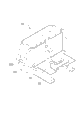
Fig. 1 is a three-dimensional exploded view of a better embodiment of electronic installation of the present invention.
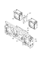
Fig. 2 is a three-dimensional exploded view of Fig. 1 combination of fans.
Fig. 3 is a stereographic map of connector in Fig. 2.
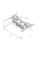
Fig. 4 is another visual angle figure of Fig. 2.
Fig. 5 is an enlarged drawing of V part in Fig. 4.
Fig. 6 is another three-dimensional exploded view of Fig. 2, and wherein, connector is rack-mount.
Fig. 7 is the three-dimensional assembly diagram of Fig. 1.
The main element symbol description
| Housing | 10 |
| |
11 |
| |
13 |
| Fixed |
131 |
| Combination of |
60 |
| Support | 20 |
| |
21 |
| Through |
211 |
| Card | 213 |
| Hole clipping | 2131 |
| The stop bit sheet | 215 |
| |
23 |
| The |
231 |
| The |
233 |
| The |
235 |
| |
25 |
| |
27 |
| |
271 |
| Flanging | 273 |
| Tumbler | 30 |
| |
31 |
| |
33 |
| |
40 |
| |
41 |
| |
411 |
| |
50 |
| First | 51 |
| |
511 |
| Clamping |
511 |
| |
53 |
Following embodiment further illustrates the present invention in connection with above-mentioned accompanying drawing.
Embodiment
Refer to Fig. 1, in a better embodiment of the present invention, a kind of electronic installation includes a housing 10 and and is arranged on the combination of fans 60 in described housing 10.
Described housing 10 includes a base plate 11 and biside plate 13.Described biside plate 13 lays respectively at the relative both sides of described base plate 11.Be separately installed with a fixed head 131 on described biside plate 13.Described fixed head 131 is provided with a holding division (not shown) in the inboard of described housing 10.
Please refer to Fig. 2-5, described combination of fans 60 includes a support 20, and is rotatably installed in tumbler 30, four fans 40 and four connectors 50 on described support 20.The both sides of each fan 40 are provided with two handles 41, and the relative both sides of described handle 41 convex with a stop section 411.
Described support 20 includes a diapire 21, two side 23, two web joints 25 and a dividing plate 27.Described two side 23 is positioned at the relative both sides of described diapire 21.Described two web joints 25 are positioned at the opposite end of described diapire 21, and connect respectively described two side 23.Described dividing plate 27 includes a plate body 271 and two flangings 273.Described plate body 271 offers a clamping hole 2711 near upper end.Described two flangings 273 extend to form from the relative both sides of described plate body 271.In one embodiment, described two flangings 273 are parallel to each other, and are approximately perpendicular to described plate body 271.Described two side 23 includes respectively one first grip block 231, one second grip block 233 and one the 3rd grip block 235.Described the second grip block 233 and described the 3rd grip block 235 lay respectively at described the first relative both sides of grip block 231.Described two first grip blocks 231 form one first fixed space (scheming not label) together with described diapire 21, described dividing plate 27 is arranged in described the first fixed space, and described the first fixed space is divided into to two receiving spaces, two described fans 40 are by described handle 41 elastic deformations, during the described clamping hole 2711 of described stop section 411 alignment, discharge described handle 41, described stop section 411 snaps in described clamping hole 2711 and described two fans 40 is fixed in described two receiving spaces.In one embodiment, described plate body 271 is substantially vertical with described two first grip blocks 231.
The described web joint 25 of described two second grip block 233, one and described diapire 21 form one second fixed space (scheming not label) together in order to fix a fan 40.Described two the 3rd grip blocks 235, another described web joint 25 and described diapire 21 surround one the 3rd fixed space (not label) together in order to fix a fan 40.
Please refer to Fig. 4 and Fig. 5, corresponding each fan 40 of described diapire 21 offers a through hole 211.Described through hole 211 roughly is a rectangle.Described diapire 21 is outward extended with respectively a card 213 in the relative two edges of described through hole 211, and another relative two edges are extended with respectively a stop bit sheet 215.Each card 213 offers a hole clipping 2131 that extends to described diapire 21.In one embodiment, described two cards 213 are parallel respectively.
Please refer to Fig. 6 and Fig. 7, described tumbler 30(is shown in Fig. 2) include the operating portion 33 that two swivel arms 31 and connect described swivel arm 31.Each swivel arm 31 is rotatably installed on every a plate 25, and offers respectively a breach (not shown).Described holding division can be stuck in described breach so that described combination of fans 60 is fixed in described housing 10, and can by rotate described operating portion 33 break away from described breach with by described combination of fans 60 from the interior dismounting of described housing 10.
Please refer to Fig. 2 and Fig. 3, every a connector 50 includes a first 51 and a second portion 53.The relative both sides of described first 51 are respectively equipped with a shell fragment 511, and described shell fragment 511 is provided with a clamping part 5111.Described second portion 53 extends to form from 51 bendings of described first.When described connector 50 is installed on described diapire 21, described connector 50 is snapped in to described through hole 211, the described clamping part 5111 of described card 213 corresponding extruding, make described shell fragment 511 elastic deformations, until during the described hole clipping 2131 of described clamping part 5111 alignment, described shell fragment 511 elasticity are recovered described clamping part 5111 is snapped in described hole clipping 2131, the described connector 50 of described two stop bit sheet 215 clamping.Thus, described connector 50 is installed on described diapire 21.While being arranged on described support 20 by described fan 40, described fan 40 is realized being electrically connected to described connector 50.
While dismantling described connector 50, push in opposite directions described two shell fragments 511, make described clamping part 5111 break away from described hole clipping 2131, and dismantle described connector 50 away from described through hole 211 place one sides.
Claims (10)
1. an electronic installation, include housing and be arranged on the combination of fans in described housing, described combination of fans includes support, fan and connector, described fan is fixed in described support, and described connector is electrically connected to described fan, and described support includes diapire, it is characterized in that: described diapire offers through hole, described connector is provided with shell fragment, and described shell fragment is stuck in described through hole and described connector is fixed on described diapire, and can break away from described through hole by elastic deformation.
2. electronic installation as claimed in claim 1, it is characterized in that: the relative two edges of described through hole are respectively equipped with a card, each card offers the hole clipping that extends to described diapire, described shell fragment is provided with clamping part, described clamping part is stuck in described hole clipping, and breaks away from described hole clipping when described shell fragment elastic deformation.
3. electronic installation as claimed in claim 2, is characterized in that: described two card almost parallels.
4. electronic installation as claimed in claim 2, it is characterized in that: described connector includes first, and described shell fragment is located at the relative both sides of described first.
5. electronic installation as claimed in claim 4, it is characterized in that: described connector comprises the second portion be connected with described first, another opposite edges of described through hole through hole are respectively equipped with a stop bit sheet, described first is clamped between described two stop bit sheets, and described second portion and a described stop bit sheet are supported.
6. electronic installation as claimed in claim 1, it is characterized in that: described fan has two, described support also includes two side and dividing plate, described two side includes respectively the first grip block, described dividing plate is arranged between described two first grip blocks, and fixes described two fans together with described diapire and described two first grip blocks.
7. electronic installation as claimed in claim 5, it is characterized in that: described dividing plate includes a plate body and two flangings, and described plate body is in order to separate and to fix described two fans, and described two flangings are separately fixed on described two side.
8. electronic installation as claimed in claim 5, it is characterized in that: described plate body offers a clamping hole, on described two fans, is respectively equipped with handle, and the handle on described two fans is stuck in described clamping hole, and can elastic deformation break away from described clamping hole.
9. electronic installation as claimed in claim 1, it is characterized in that: described combination of fans also includes tumbler, and described tumbler is rotatably installed on described support.
10. electronic installation as claimed in claim 9, it is characterized in that: described housing includes biside plate, and described tumbler is stuck between described biside plate, and can rotate to break away from described side plate relative to described side plate.
Priority Applications (3)
| Application Number | Priority Date | Filing Date | Title |
|---|---|---|---|
| CN201210189908.2A CN103488248A (en) | 2012-06-11 | 2012-06-11 | Electronic device |
| TW101121702A TW201352116A (en) | 2012-06-11 | 2012-06-18 | Electronic apparatus |
| US13/543,648 US8848357B2 (en) | 2012-06-11 | 2012-07-06 | Electronic device with connector |
Applications Claiming Priority (1)
| Application Number | Priority Date | Filing Date | Title |
|---|---|---|---|
| CN201210189908.2A CN103488248A (en) | 2012-06-11 | 2012-06-11 | Electronic device |
Publications (1)
| Publication Number | Publication Date |
|---|---|
| CN103488248A true CN103488248A (en) | 2014-01-01 |
Family
ID=49715148
Family Applications (1)
| Application Number | Title | Priority Date | Filing Date |
|---|---|---|---|
| CN201210189908.2A Pending CN103488248A (en) | 2012-06-11 | 2012-06-11 | Electronic device |
Country Status (3)
| Country | Link |
|---|---|
| US (1) | US8848357B2 (en) |
| CN (1) | CN103488248A (en) |
| TW (1) | TW201352116A (en) |
Families Citing this family (5)
| Publication number | Priority date | Publication date | Assignee | Title |
|---|---|---|---|---|
| CN104122937A (en) * | 2013-04-23 | 2014-10-29 | 鸿富锦精密工业(武汉)有限公司 | Connector fixing device |
| TWI583293B (en) * | 2015-12-28 | 2017-05-11 | 鴻海精密工業股份有限公司 | Fixing device |
| US10362708B2 (en) * | 2017-09-06 | 2019-07-23 | Facebook, Inc. | Fan cartridge |
| TWI805985B (en) * | 2021-01-13 | 2023-06-21 | 緯創資通股份有限公司 | Case |
| US11690190B2 (en) * | 2021-04-26 | 2023-06-27 | Quanta Computer Inc. | System component carrier with ejector |
Family Cites Families (4)
| Publication number | Priority date | Publication date | Assignee | Title |
|---|---|---|---|---|
| TWM254872U (en) * | 2004-03-09 | 2005-01-01 | Hon Hai Prec Ind Co Ltd | Mounting apparatus for drive bracket |
| CN2799933Y (en) * | 2005-06-18 | 2006-07-26 | 鸿富锦精密工业(深圳)有限公司 | Fan fixing device |
| CN102467204A (en) * | 2010-11-18 | 2012-05-23 | 鸿富锦精密工业(深圳)有限公司 | Fan fixing device |
| CN103455106A (en) * | 2012-05-28 | 2013-12-18 | 鸿富锦精密工业(深圳)有限公司 | Air fan fixing device |
-
2012
- 2012-06-11 CN CN201210189908.2A patent/CN103488248A/en active Pending
- 2012-06-18 TW TW101121702A patent/TW201352116A/en unknown
- 2012-07-06 US US13/543,648 patent/US8848357B2/en not_active Expired - Fee Related
Also Published As
| Publication number | Publication date |
|---|---|
| US20130329371A1 (en) | 2013-12-12 |
| US8848357B2 (en) | 2014-09-30 |
| TW201352116A (en) | 2013-12-16 |
Similar Documents
| Publication | Publication Date | Title |
|---|---|---|
| CN103488248A (en) | Electronic device | |
| CN201097294Y (en) | Fixing structure combination for shielding device | |
| CN102548344A (en) | Fan assembly | |
| CN201298198Y (en) | Fan mounting device | |
| CN102981572A (en) | Electronic device shell | |
| CN102023677A (en) | Computer system | |
| CN103140107A (en) | Electronic device casing | |
| CN102566692B (en) | Expansion card fixer | |
| CN101861077A (en) | Fan fixing device | |
| CN102738647B (en) | Connector assembly | |
| CN102654791A (en) | Electronic device | |
| CN102841657A (en) | Expansion card fixing device | |
| CN102445972A (en) | Electronic equipment shell | |
| CN103576798A (en) | Fan fixing device | |
| CN103389783A (en) | PCI (Peripheral Component Interconnect) card-fixing structure | |
| CN103092263A (en) | Fan fixing device | |
| CN205488651U (en) | Electronic card device | |
| CN102683986B (en) | Connector assembly | |
| US8035962B2 (en) | Computer hot-plug structure | |
| CN103379792A (en) | Housing for fixing mainboard and electronic apparatus having housing | |
| CN103176543A (en) | Fixing device for data storage device | |
| CN103365381A (en) | Fan fixing device | |
| CN102981571A (en) | Electronic device shell | |
| CN103123531A (en) | Electronic device shell body | |
| CN105022457A (en) | Hard disk fixing bracket and computer case |
Legal Events
| Date | Code | Title | Description |
|---|---|---|---|
| C06 | Publication | ||
| PB01 | Publication | ||
| C02 | Deemed withdrawal of patent application after publication (patent law 2001) | ||
| WD01 | Invention patent application deemed withdrawn after publication |
Application publication date: 20140101 |