CN103273344A - Work clamp matched with universal miller and used for milling seam faces of glass molds - Google Patents
Work clamp matched with universal miller and used for milling seam faces of glass molds Download PDFInfo
- Publication number
- CN103273344A CN103273344A CN2013101662616A CN201310166261A CN103273344A CN 103273344 A CN103273344 A CN 103273344A CN 2013101662616 A CN2013101662616 A CN 2013101662616A CN 201310166261 A CN201310166261 A CN 201310166261A CN 103273344 A CN103273344 A CN 103273344A
- Authority
- CN
- China
- Prior art keywords
- milling cutter
- support
- adjustment
- die holder
- screw rod
- Prior art date
- Legal status (The legal status is an assumption and is not a legal conclusion. Google has not performed a legal analysis and makes no representation as to the accuracy of the status listed.)
- Pending
Links
Images

Abstract
The invention discloses a work clamp matched with a universal miller and used for milling seam faces of glass molds. The universal miller comprises a miller main shaft and a miller working platform. The work clamp comprises a baseboard, a first adjustment support, a second adjustment support, a guide rail seat, a fixed mold clamping seat, a movable mold clamping seat and a screw, wherein the baseboard is arranged on the miller working platform, the first adjustment support and the second adjustment support are arranged at the two ends of the baseboard, at least one first adjustment pressing plate and one second adjustment pressing plate are arranged on the top portion of the first adjustment support and on the top of the second adjustment support, the guide rail seat is fixedly arranged on the middle portion of the baseboard, a pair of guide rails are formed on the guide rail seat, the fixed mold clamping seat corresponds to the movable mold clamping seat, a screw sliding sleeve is configured on the movable mold clamping seat, one end of the screw is connected with the fixed mold clamping seat, the other end of the screw is matched with the screw sliding sleeve, and a screw manipulation handle is fixedly arranged on the end portion, extending out of the screw sliding sleeve, of the screw. The work clamp matched with the universal miller and used for milling the seam faces of the glass molds is convenient to manufacture, to use and to maintain, cheap, capable of meeting the requirement of machining concave arc surfaces on the seam faces of the glass molds, high in machining efficiency, not heavy in working strength, and is suitable for molds of different standards. Further, by means of the work clamp, the glass molds do not loose when the glass molds are milled with milling cutters.
Description
Technical field
The invention belongs to technical field of tooling clamps, be specifically related to frock clamp a kind of and the glass mold joint close facing cut processing usefulness that universal milling machine is supporting.
Background technology
Frock clamp plays a part very important in the production of industrial products, and the processing of glass mold is no exception.So-called frock clamp refers to in machining workpiece being carried out clamping or location, to reach special equipment or the instrument of certain technological requirement.Frock clamp need satisfy does not usually have interference when production, accurate positioning is reliable and requirement such as handiness.Make the exclusive of certain product because frock clamp has, so the generalization degree is low, often by manufacturer's self manufacture of producing product, glass mold production firm also is equipped with various frock clamps in homemade mode mostly.Because glass mold especially container glass mold exists with the form of two-half die opposite each other substantially, and owing to the reason of considering that mould expands with heat and contract with cold at the glass bottle and jar make-up machine, design and the processed glass mould joint close face of being everlasting often carries out milling processing in advance, and milling depth is shoaled until vanishing to both sides gradually by the middle position of the length direction of joint close face, and this procedure is called " drawing the plane " usually by industry.And why on the joint close face of glass mold, Milling Process come from the cancave cambered surface that the middle part shoals gradually to two ends, be because glass mold under arms in the process, the temperature at middle part is higher, the coefficient of expansion is big, be that deformation extent is relatively large, thereby the cancave cambered surface that the degree by design is generally 0.1-0.35 ㎜ is compensated, use the matched moulds effect that embodies ideally between the two-half die, ensureing the quality of Bottle ﹠ Can class glassware, otherwise can stay impressively visible overlap (being raised in the muscle of glassware outer wall surface) and diminish sight at Bottle ﹠ Can class glassware.
Prior art mainly contains following two kinds to the processing mode that processes cancave cambered surface on the glass mold joint close face; The one, filed out with file by veteran workman (pincers worker), labor strength is big, efficient is low and the shortcoming of difficult quality guarantee but this manual mode exists; The 2nd, utilize numerical control machining center to mill processing, though this mode can remedy the shortcoming of the former manual file processing to a certain extent, but owing to start with and need convert a camber line or title segmental arc to some straightways from the program composition theory, so the fineness of milling face is relatively poor and Milling Process efficient is still lower.In addition because the numerical control machining center investment is big, therefore iff purchasing the waste that expensive machining center can cause device resource undoubtedly for the joint close facing cut of glass mold being cut the processing cancave cambered surface, and as common glass production manufacturer to expensive numerical control machining center often hang back (because of the preparation investment big).
Undoubtedly, utilizing common universal milling machine that glass mold joint close facing cut is cut processing can make the shortcoming of above-mentioned two kinds of processing modes effectively remedy, but since lack at present with universal milling machine supporting be used for frock clamp that glass mold is reliably clamped, thereby industry still can only helplessly to rely on manual processing be aforesaidly to adopt file to the processing of joint close face file by the workman.
In view of above-mentioned prior art, be necessary to be improved, the applicant has done useful design for this reason, has formed technical scheme described below finally, and taking to have carried out the simulation use in the applicant plant area under the strict secrecy provision, it is practicable that the result proves.
Summary of the invention
Task of the present invention is to provide a kind of and helps remarkable simplified structure and use and reduce manufacture difficulty and reduce use cost and embody handled easily and maintenance, is conducive to break away from the processing of file file and uses the operation intensity that significantly alleviates the workman and improve working (machining) efficiency and be of value to that guarantee crudy and the frock clamp supporting glass mold joint close facing cut processing usefulness of universal milling machine.
Task of the present invention is finished like this, the frock clamp of the glass mold joint close facing cut processing usefulness that a kind of and universal milling machine is supporting, described universal milling machine comprises milling machine spindle and milling machine workbench, end at milling machine spindle fixedly has a milling cutter fixed disk, be equipped with milling cutter at the milling cutter fixed disk, the frock clamp of described glass mold joint close facing cut processing usefulness comprises: a base plate, this base plate are arranged on the described milling machine workbench; One first adjusts support and one second adjusts support, first adjusts the end that support is arranged on described base plate, and be provided with at least one piece first at this first top of adjusting support and adjust pressing plate, second adjusts the other end that support is arranged on base plate, and corresponding with the first adjustment support, be provided with at least one piece second equally at this second top of adjusting support and adjust pressing plate; One track base, this track base is fixed on the middle part of described base plate, and constitutes a pair of parallel guide rail at this track base; One geometrical clamp die holder and a live splint die holder, geometrical clamp die holder and live splint die holder correspond to each other, and the geometrical clamp die holder is fixed with an end of described track base between corresponding to described pair of guide rails, and the live splint die holder is slidingly matched with pair of guide rails between corresponding to pair of guide rails, wherein: be equipped with a screw rod sliding sleeve at described live splint die holder; One screw rod, an end and the geometrical clamp die holder of this screw rod are rotationally connected, and the other end of screw rod matches with described screw rod sliding sleeve, and lean out the screw rod sliding sleeve, in the end of the described other end of this screw rod that leans out the screw rod sliding sleeve one screw rod control crank are arranged fixedly.
In a specific embodiment of the present invention, described milling cutter fixed disk is in the form of annular discs, and the middle position at this milling cutter fixed disk constitutes the facing cutter holder, this facing cutter holder is fixedlyed connected with described milling machine spindle, offer at least one milling cutter position at the milling cutter fixed disk and adjust groove, described milling cutter is fixed at position and the milling cutter fixed disk of adjusting groove corresponding to the milling cutter position.
In another specific embodiment of the present invention, described milling cutter is equipped with a milling cutter seat, and this milling cutter seat is fixed together with milling cutter and milling cutter fixed disk at the position of adjusting groove corresponding to described milling cutter position.
In another specific embodiment of the present invention, constitute a milling cutter seat standing screw at described milling cutter seat, this milling cutter seat standing screw inserts described milling cutter position and adjusts groove, and fixed by the screw rod hold-down nut that is provided on the milling cutter seat standing screw, on the milling cutter seat standing screw, also be equipped with one and adjust the sliding nut that groove is slidingly matched with described milling cutter position.
In another specific embodiment of the present invention, offer a pair of first parallel support at the described end of described base plate and adjust groove, described first adjusts support is adjusting the position of groove corresponding to first support and a described end of base plate is being fixed; The described other end at base plate offers a pair of second support adjustment groove that walks abreast mutually, and described second adjusts support is fixing corresponding to the position of second support adjustment groove and the described other end of base plate.
Also have in the specific embodiment of the present invention, adjust pressing plate described first and offer the first adjustment groove, adjust screw by first and in the position for the first adjustment groove the first adjustment pressing plate and the first described top of adjusting support are being fixed, and the first adjustment pressing plate leans out the first adjustment support towards a side side of the described second adjustment support towards described second end of adjusting pressing plate with level; Adjust pressing plate described second and offer the second adjustment groove, adjust screw by second and in the position corresponding to the second adjustment groove the second adjustment pressing plate and the second described top of adjusting support are being fixed, and the second adjustment pressing plate leans out the second adjustment support towards a side side of the described first adjustment support towards described first end of adjusting pressing plate with level.
More of the present invention and in specific embodiment, on described geometrical clamp die holder and towards a side surface of described live splint die holder, constitute the first clamping tooth, and on the live splint die holder and towards a side surface of geometrical clamp die holder, constitute the second clamping tooth.
In of the present invention and then specific embodiment, described first adjusts support and second adjusts the structure that support all is the square shape of Chinese character.
Of the present invention again more and in specific embodiment, the one handle nut is arranged fixedly on the described screw rod control crank, the end face of the described other end of this handle nut and described screw rod is fixed.
One of technique effect that technical scheme provided by the invention has because overall structure is terse, thereby can conveniently make, operation and maintenance, and cheap; Two because the base plate that provides can match with the milling machine workbench of universal milling machine, thereby can satisfy processing the requirement of cancave cambered surface on the joint close face of glass mold and guaranteeing crudy; Three owing to need not artificial file processing, thereby it is high and significantly alleviate the strong point of workman's operation intensity to have working (machining) efficiency; Four owing to can be adjusted the synergy of pressing plate and the reliable location of glass mold is clamped by first, second, thereby glass mold loosening situation can not occur being milled by milling cutter in the process; Five because first, second position of adjusting support can adjust at base plate, thereby the mould of different size is had good adaptability.
Description of drawings
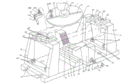
Fig. 1 is the embodiments of the invention structure chart.
Fig. 2 is application examples schematic diagram of the present invention.
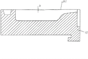
Fig. 3 is the schematic diagram after utilizing the present invention to the joint close face processing of glass mold.
The specific embodiment
See also Fig. 1 and Fig. 2, milling machine spindle 1 and the milling machine workbench 2 of the structural system that belongs to universal milling machine have been provided, according to industry technique known general knowledge, therefore the angle of the milling machine spindle 1 of universal milling machine can be regulated arbitrarily, drives variation with the angle of inclination of its fixing milling cutter fixed disk 2 along with the variation at the angle of inclination of milling machine spindle 1 by milling machine spindle 1.By shown in Figure 1, middle position at discoid milling cutter fixed disk 11 constitutes a facing cutter holder 112, this facing cutter holder 112 is fixed with the flat key on the milling machine spindle 1, offer a pair of milling cutter position that is distributed in each other on the same straight line at milling cutter fixed disk 11 and adjust groove 113, the side that groove 113 is positioned at facing cutter holder 112 is adjusted in wherein milling cutter position that this a pair of milling cutter position is adjusted in the groove 113, and the opposite side that groove 113 is positioned at facing cutter holder 112 is adjusted in another milling cutter position.Appointing in a pair of milling cutter position adjustment groove 113 selected a milling cutter position adjustment groove 113 fixedly a milling cutter 111, that is to say that milling cutter 111 is fixing at the position of adjusting groove 113 corresponding to the milling cutter position and milling cutter fixed disk 11.The milling cutter 111 that is fixed thereon is tilted, thereby make its movement locus form a cambered surface.
By shown in Figure 1, aforesaid milling cutter 111 is furnished with a milling cutter seat 1111, and this milling cutter seat 1111 is fixing with milling cutter fixed disk 11 together with milling cutter 111 at the position of adjusting groove 113 corresponding to the milling cutter position.Again, at milling cutter seat 1111 a milling cutter seat standing screw 11111 is arranged fixedly, and be equipped with screw rod hold-down nut 11112a at this milling cutter seat standing screw 11111, after milling cutter seat standing screw 11111 is placed in milling cutter position adjustment groove 113, namely cooperate back (back is determined in the position of adjusting on the groove 113 in the milling cutter position) to be fixed by screw rod hold-down nut 11112a with milling cutter position adjustment groove 113 by the sliding nut 11112b that is equipped on the milling cutter seat standing screw 11111, because screw rod hold-down nut 11112a is corresponding to the top of milling cutter fixed disk 11.Milling cutter 111 is clamped and fastened on the milling cutter seat 1111 by pinching screw 11112.
Milling cutter seat 1111 can be adjusted groove 113 together with milling cutter 111 in the milling cutter position and implement to adjust according to the specifications vary of glass mold 10.
Provided a base plate 3 of the structural system of the frock clamp that belongs to glass mold joint close facing cut processing usefulness of the present invention, this base plate 3 is cuboidal configuration substantially, on the milling machine workbench 2 that is matched under the use state by Fig. 2 signal.End at this base plate 3 offers a pair of first parallel support adjustment groove 31, and offers a pair of second support adjustment groove 32 that walks abreast mutually at the other end of base plate 3, and a pair of first, second support is adjusted groove 31,32 maintenances are corresponding.
Provided one first of the structural system that belongs to frock clamp and adjusted support 4 and one second and adjust support 5, first, second adjusts " mouth " font that support 4,5 geometry all are Chinese character substantially.Be provided with a pair of first at first top of adjusting support 4 and adjust pressing plate 41, offer one first at each first adjustment pressing plate 41 and adjust groove 411, adjust screw 4111 with first and corresponding to first position of adjusting groove 411 first top of adjusting pressing plate 41 and first adjustment rack 4 is being fixed.First lower end of adjusting support 4 is being fixed corresponding to the position of a pair of first support adjustment groove 31 and an aforementioned end of base plate 3 with an a pair of T shape screw 42, and limits nut 421 lockings by first.Be provided with a pair of second at second top of adjusting support 5 and adjust pressing plate 51, offer one second at each second adjustment pressing plate 51 and adjust groove 511, adjust screw 5111 with second and corresponding to second position of adjusting groove 511 second top of adjusting pressing plate 51 and the second adjustment support 5 is being fixed.Second lower end of adjusting support 5 is being fixed corresponding to the position of a pair of second support adjustment groove 32 and the aforementioned other end of base plate 3 with a pair of the 2nd T shape screw 52, and limits nut 521 lockings by second.
Shown in figure, under the clamp position of the glass mold of in to figure, illustrating 10, aforesaid a pair of first adjusts pressing plate 41 leans out the first adjustment support 4 towards the side of a side of the second adjustment support 5 towards second end of adjusting pressing plate 51 with level, equally, a pair of second adjust pressing plate 51 and lean out second towards first end of adjusting pressing plate 41 with level and adjust support 5 towards second side of adjusting a side of support 4.First adjusting range of adjusting pressing plate 41 depends on that first adjusts the length of groove 411, and second adjusting range of adjusting pressing plate 51 depends on that second adjusts the length of groove 511.Again, first adjusting range of adjusting support 4 depends on that a pair of first support adjusts the length of groove 31, and second adjusting range of adjusting support 5 depends on that a pair of second support adjusts the length of groove 32, whether need to adjust then depend on glass mold 10 variation whether.
Provided a track base 6, this track base 6 is fixed on the middle part of base plate 3, namely adjusts between the support 4,5 at first, second, constitutes a pair of parallel guide rail 61 at this track base 6.No matter be that track base 6 and base plate 3 is integrally formed or track base 6 is fixed in base plate 3 as single-row parts, all should be considered as the technology of the present invention content category.
A geometrical clamp die holder 7 and a live splint die holder 8 have been provided, geometrical clamp die holder 7 corresponds to each other with live splint die holder 8, and geometrical clamp die holder 7 (being positioned at an end of pair of guide rails 61) between corresponding to aforesaid pair of guide rails 61 is fixed with an end of track base 6, and live splint die holder 8 (being positioned at the other end of pair of guide rails 61) between corresponding to pair of guide rails 61 is slidingly matched with pair of guide rails.Wherein: live splint die holder 8 is provided with a screw rod sliding sleeve 82.
In order to embody the good effect of clamping to glass mold 10, on aforesaid geometrical clamp die holder 7 and towards the surface of a side of live splint die holder 8, constitute the first clamping tooth 71, and on live splint die holder 8 and towards the surface of a side of geometrical clamp die holder 7, constitute the second clamping tooth 81.By shown in Figure 1, geometrical clamp die holder 7 and live splint pattern seat 8 form the position relation just as the V font of English alphabet each other, that is to say that geometrical clamp die holder 7 is preferably 45 ° inclination wall body towards the formation of the top of the wall body of a side of live splint die holder 8, and live splint die holder 8 forms the inclination wall body that is preferably 45 ° equally towards the top of the wall body of a side of geometrical clamp die holder 7.
Scold out with respect to geometrical clamp die holder 7 or to the direction displacement of geometrical clamp die holder 7 in order to make live splint die holder 8, thereby provided a screw rod 9, one end of this screw rod 9 is connected on the geometrical clamp die holder 7 rotationally, and the other end of screw rod 9 is connected on the live splint die holder 8, more precisely cooperate with screw rod sliding sleeve 82 on the live splint die holder 8 and lean out screw rod sliding sleeve 82, screw rod 9 lean out screw rod sliding sleeve 82 the end each a screw rod control crank 91 is fixedly arranged.Shown in figure, one handle nut 911 is fixedly arranged on the screw rod control crank 91, this handle nut 911 is fixed with the end of screw rod 9.
Ask for an interview Fig. 3, this Fig. 3 has illustrated to process the cancave cambered surface that the degree of depth is generally 0.1-0.35 ㎜ at the joint close face 101 of glass mold 10, and this cancave cambered surface shoals to two ends from the middle position of the length direction of joint close face 101 gradually until being zero.The applicant has marked the D of English alphabet in the middle position of the length direction of joint close face 101, namely represent the degree of depth by D.
In the time need milling out cancave cambered surface to the joint close face 101 of glass mold 10, the state that earlier glass mold 10 is made progress with its die cavity places between geometrical clamp die holder 7 and the live splint die holder 8, the end face of one end of glass mold 10 and first is adjusted support 4 towards a side contacts of the second adjustment support 5, and the end face of the other end of glass mold 10 and second is adjusted support 5 towards a side contacts of the first adjustment support 4, and first, second is adjusted pressing plate 41,51 be in by state illustrated in figures 1 and 2, namely the two ends of glass mold 10 are located.Make screw rod 9 drive live splint die holder 8 towards the direction displacement of geometrical clamp die holder 7 by the operator by the operation to screw rod control crank 91, cooperate live splint die holder 8 jointly the both sides of glass mold 10 to be clamped by geometrical clamp die holder 7.Finished under the state of adjusting in the angle of milling machine spindle 1, order about universal milling machine work, drive milling cutter fixed disk 11 by milling machine spindle 1, drive the milling cutter 111 that is fixed on the milling cutter seat 1111 by milling cutter fixed disk 11, mill out cancave cambered surface by milling cutter 111 at joint close face 101, namely finish aforesaid " drawing the plane ".
In sum, technical scheme provided by the invention has remedied the shortcoming in the prior art, has successfully finished the invention task, has embodied the technique effect that refers in the superincumbent technique effect of the applicant hurdle.
Claims (9)
1.
The frock clamp of the glass mold joint close facing cut processing usefulness that a kind of and universal milling machine is supporting, described universal milling machine comprises milling machine spindle (1) and milling machine workbench (2), end at milling machine spindle (1) fixedly has a milling cutter fixed disk (11), be equipped with milling cutter (111) at milling cutter fixed disk (11), the frock clamp that it is characterized in that described glass mold joint close facing cut processing usefulness comprises: a base plate (3), this base plate (3) are arranged on the described milling machine workbench (2); One first adjusts support (4) and one second adjusts support (5), first adjusts the end that support (4) is arranged on described base plate (3), and be provided with at least one piece first at this first top of adjusting support (4) and adjust pressing plate (41), second adjusts the other end that support (5) is arranged on base plate (3), and corresponding with the first adjustment support (4), be provided with at least one piece second equally at this second top of adjusting support (5) and adjust pressing plate (51); One track base (6), this track base (6) is fixed on the middle part of described base plate (3), and constitutes a pair of parallel guide rail (61) at this track base (6); One geometrical clamp die holder (7) and a live splint die holder (8), geometrical clamp die holder (7) corresponds to each other with live splint die holder (8), and geometrical clamp die holder (7) is fixed with an end of described track base (6) between corresponding to described pair of guide rails (61), and live splint die holder (8) is slidingly matched with pair of guide rails (61) between corresponding to pair of guide rails (61), wherein: be equipped with a screw rod sliding sleeve (82) at described live splint die holder (8); One screw rod (9), one end of this screw rod (9) and geometrical clamp die holder (7) are rotationally connected, and the other end of screw rod (9) matches with described screw rod sliding sleeve (82), and lean out screw rod sliding sleeve (82), in the end of the described other end of this screw rod (9) that leans out screw rod sliding sleeve (82) a screw rod control crank (91) is arranged fixedly.
2.
The frock clamp of the glass mold joint close facing cut processing usefulness that according to claim 1 and universal milling machine is supporting, it is characterized in that described milling cutter fixed disk (11) is in the form of annular discs, and the middle position at this milling cutter fixed disk (11) constitutes facing cutter holder (112), this facing cutter holder (112) is fixedlyed connected with described milling machine spindle (1), offer at least one milling cutter position at milling cutter fixed disk (11) and adjust groove (113), described milling cutter (111) is fixing at position and the milling cutter fixed disk (11) of adjusting groove (113) corresponding to the milling cutter position.
3.
The frock clamp of the glass mold joint close facing cut processing usefulness that according to claim 2 and universal milling machine is supporting, it is characterized in that described milling cutter (111) is equipped with a milling cutter seat (1111), this milling cutter seat (1111) is fixing together with milling cutter (111) and milling cutter fixed disk (11) at the position of adjusting groove (113) corresponding to described milling cutter position.
4.
The frock clamp of the glass mold joint close facing cut processing usefulness that according to claim 3 and universal milling machine is supporting, it is characterized in that constituting a milling cutter seat standing screw (11111) at described milling cutter seat (1111), this milling cutter seat standing screw (11111) inserts described milling cutter position and adjusts groove (113), and fixing by the screw rod hold-down nut (11112a) that is provided on the milling cutter seat standing screw (11111), on milling cutter seat standing screw (11111), also be equipped with one and adjust the sliding nut (11112b) that groove (113) is slidingly matched with described milling cutter position.
5.
The frock clamp of the glass mold joint close facing cut processing usefulness that according to claim 1 and universal milling machine is supporting, it is characterized in that offering a pair of first parallel support adjustment groove (31) at a described end of described base plate (3), described first adjusts support (4) is fixing corresponding to the position of first support adjustment groove (31) and a described end of base plate (3); The described other end at base plate (3) offers a pair of second support adjustment groove (32) that walks abreast mutually, and described second adjusts support (5) is fixing corresponding to the position of second support adjustment groove (32) and the described other end of base plate (3).
6.
The frock clamp of the glass mold joint close facing cut processing usefulness that according to claim 1 and universal milling machine is supporting, it is characterized in that adjusting pressing plate (41) described first offers the first adjustment groove (411), the first adjustment pressing plate (41) and the first described top of adjusting support (4) are being fixed for first position of adjusting groove (411) by the first adjustment screw (4111), and the first adjustment pressing plate (41) leans out the first adjustment support (4) towards a side side of the described second adjustment support (5) towards described second end of adjusting pressing plate (51) with level; Adjust pressing plate (51) described second and offer the second adjustment groove (511), the second adjustment pressing plate (51) and the second described top of adjusting support (5) are being fixed corresponding to second position of adjusting groove (511) by the second adjustment screw (5111), and the second adjustment pressing plate (51) leans out the second adjustment support (5) towards a side side of the described first adjustment support (4) towards described first end of adjusting pressing plate (41) with level.
7.
The frock clamp of the glass mold joint close facing cut processing usefulness that according to claim 1 and universal milling machine is supporting, it is characterized in that going up and constituting the first clamping tooth (71) towards a side surface of described live splint die holder (8) at described geometrical clamp die holder (7), and go up and constitute the second clamping tooth (81) towards a side surface of geometrical clamp die holder (7) at live splint die holder (8).
8.
Process the frock clamp of usefulness according to claim 1 or 6 glass mold joint close facing cuts described and that universal milling machine is supporting, it is characterized in that the described first adjustment support (4) and the second adjustment support (5) all are the structure of the square shape of Chinese character.
9.
The frock clamp of the glass mold joint close facing cut processing usefulness that according to claim 1 and universal milling machine is supporting, it is characterized in that described screw rod control crank (91) upward fixedly has one handle nut (911), this handle nut (911) is fixed with the end face of the described other end of described screw rod (9)
Priority Applications (1)
| Application Number | Priority Date | Filing Date | Title |
|---|---|---|---|
| CN2013101662616A CN103273344A (en) | 2013-05-08 | 2013-05-08 | Work clamp matched with universal miller and used for milling seam faces of glass molds |
Applications Claiming Priority (1)
| Application Number | Priority Date | Filing Date | Title |
|---|---|---|---|
| CN2013101662616A CN103273344A (en) | 2013-05-08 | 2013-05-08 | Work clamp matched with universal miller and used for milling seam faces of glass molds |
Publications (1)
| Publication Number | Publication Date |
|---|---|
| CN103273344A true CN103273344A (en) | 2013-09-04 |
Family
ID=49056021
Family Applications (1)
| Application Number | Title | Priority Date | Filing Date |
|---|---|---|---|
| CN2013101662616A Pending CN103273344A (en) | 2013-05-08 | 2013-05-08 | Work clamp matched with universal miller and used for milling seam faces of glass molds |
Country Status (1)
| Country | Link |
|---|---|
| CN (1) | CN103273344A (en) |
Cited By (4)
| Publication number | Priority date | Publication date | Assignee | Title |
|---|---|---|---|---|
| CN105127790A (en) * | 2015-09-14 | 2015-12-09 | 苏州东方模具科技股份有限公司 | Tool clamp for machining outer circle of glass mold |
| CN106078252A (en) * | 2016-06-30 | 2016-11-09 | 湖北三江航天红阳机电有限公司 | A kind of with fiberglass cambered surface and the clamp for machining of ladder hole type parts and processing method |
| CN110561150A (en) * | 2019-09-20 | 2019-12-13 | 常熟建华模具科技股份有限公司 | Clamp structure for processing V-shaped groove at end part of matching surface of glass mold |
| CN113134770A (en) * | 2021-04-21 | 2021-07-20 | 常熟建华模具科技股份有限公司 | Clamp for maintaining glass mold |
Citations (8)
| Publication number | Priority date | Publication date | Assignee | Title |
|---|---|---|---|---|
| US3590893A (en) * | 1967-01-21 | 1971-07-06 | Tadeusz Burkiewicz | Method of fastening blades to sawing tools |
| CN87215467U (en) * | 1987-11-11 | 1988-07-13 | 太原机械学院 | End milling cutter for hobbing machine |
| JP2008088016A (en) * | 2006-10-02 | 2008-04-17 | Nihon Taisanbin Glass Bottle Mfg Co Ltd | Mold opening/closing apparatus for glass bottle making machine |
| CN102259346A (en) * | 2011-02-16 | 2011-11-30 | 苏州天风环保科技有限公司 | Adjustable multifunctional edge trimmer |
| CN102581657A (en) * | 2012-03-16 | 2012-07-18 | 常熟市伟恒模具铸造有限公司 | Fixture structure for processing glass molds |
| CN103056428A (en) * | 2013-01-15 | 2013-04-24 | 北京理工大学 | Combined numerical control milling machine |
| CN103056693A (en) * | 2013-01-29 | 2013-04-24 | 苏州东方模具科技股份有限公司 | Work fixture for machining inner cavities and joint closing surfaces of glass molds |
| CN203254193U (en) * | 2013-05-08 | 2013-10-30 | 苏州东方模具科技股份有限公司 | Tool clamp which is matched with universal milling machine and used for milling joint faces of glass molds |
-
2013
- 2013-05-08 CN CN2013101662616A patent/CN103273344A/en active Pending
Patent Citations (8)
| Publication number | Priority date | Publication date | Assignee | Title |
|---|---|---|---|---|
| US3590893A (en) * | 1967-01-21 | 1971-07-06 | Tadeusz Burkiewicz | Method of fastening blades to sawing tools |
| CN87215467U (en) * | 1987-11-11 | 1988-07-13 | 太原机械学院 | End milling cutter for hobbing machine |
| JP2008088016A (en) * | 2006-10-02 | 2008-04-17 | Nihon Taisanbin Glass Bottle Mfg Co Ltd | Mold opening/closing apparatus for glass bottle making machine |
| CN102259346A (en) * | 2011-02-16 | 2011-11-30 | 苏州天风环保科技有限公司 | Adjustable multifunctional edge trimmer |
| CN102581657A (en) * | 2012-03-16 | 2012-07-18 | 常熟市伟恒模具铸造有限公司 | Fixture structure for processing glass molds |
| CN103056428A (en) * | 2013-01-15 | 2013-04-24 | 北京理工大学 | Combined numerical control milling machine |
| CN103056693A (en) * | 2013-01-29 | 2013-04-24 | 苏州东方模具科技股份有限公司 | Work fixture for machining inner cavities and joint closing surfaces of glass molds |
| CN203254193U (en) * | 2013-05-08 | 2013-10-30 | 苏州东方模具科技股份有限公司 | Tool clamp which is matched with universal milling machine and used for milling joint faces of glass molds |
Cited By (5)
| Publication number | Priority date | Publication date | Assignee | Title |
|---|---|---|---|---|
| CN105127790A (en) * | 2015-09-14 | 2015-12-09 | 苏州东方模具科技股份有限公司 | Tool clamp for machining outer circle of glass mold |
| CN106078252A (en) * | 2016-06-30 | 2016-11-09 | 湖北三江航天红阳机电有限公司 | A kind of with fiberglass cambered surface and the clamp for machining of ladder hole type parts and processing method |
| CN106078252B (en) * | 2016-06-30 | 2018-07-06 | 湖北三江航天红阳机电有限公司 | A kind of clamp for machining and processing method with fiberglass cambered surface and ladder hole type parts |
| CN110561150A (en) * | 2019-09-20 | 2019-12-13 | 常熟建华模具科技股份有限公司 | Clamp structure for processing V-shaped groove at end part of matching surface of glass mold |
| CN113134770A (en) * | 2021-04-21 | 2021-07-20 | 常熟建华模具科技股份有限公司 | Clamp for maintaining glass mold |
Similar Documents
| Publication | Publication Date | Title |
|---|---|---|
| CN203254193U (en) | Tool clamp which is matched with universal milling machine and used for milling joint faces of glass molds | |
| CN103273344A (en) | Work clamp matched with universal miller and used for milling seam faces of glass molds | |
| CN204449961U (en) | For transformer body pressing plate/supporting plate inclined hole locating and machining frock | |
| CN204019206U (en) | A kind of five degree of freedom bench vice | |
| CN102363274A (en) | Transversely self-driven three-dimensional copying machining method and three-dimensional copying machine | |
| CN105127790A (en) | Tool clamp for machining outer circle of glass mold | |
| CN105364571A (en) | Universal cutting machine | |
| CN104741950A (en) | Burr-free cutting clamp based on support | |
| CN106625047B (en) | Arc cutter grinding machine, tool clamp thereof and use method | |
| CN201922357U (en) | Improved structure of precision flatnosed pliers | |
| CN201997722U (en) | Combined tool holder for processing end cover of motor | |
| CN205951202U (en) | Accurate cutting device of optics injection molding runner | |
| CN218168419U (en) | Vertical pneumatic die for single-side and double-side flanging of sheet metal cylinder | |
| CN105414621A (en) | Machining method for blade rabbet with asymmetric pressure faces | |
| CN206795253U (en) | A kind of double Z axis double-workbench carving machines | |
| CN103264184B (en) | Mold for seam trimming of titanium alloy straight pipe and method for machining seam trimming | |
| CN203092196U (en) | Work fixture used for machining of inner cavity and joint close surface of glass mold | |
| CN204277817U (en) | Adjustable type bench vice | |
| CN204321315U (en) | A kind of guide rail blanking cutting tool | |
| CN105773204A (en) | Workpiece machining device | |
| CN202015883U (en) | Apparatus for processing gear surface of gear | |
| CN204504801U (en) | A kind of few impulse-free robustness clamp for cutting based on supporter | |
| CN211915373U (en) | Blank positioning device for common die forging of large-scale equipment | |
| CN204123211U (en) | A kind of milling cutter grinding machine | |
| JP5939290B2 (en) | Scribing method and scribing apparatus |
Legal Events
| Date | Code | Title | Description |
|---|---|---|---|
| C06 | Publication | ||
| PB01 | Publication | ||
| C10 | Entry into substantive examination | ||
| SE01 | Entry into force of request for substantive examination | ||
| C02 | Deemed withdrawal of patent application after publication (patent law 2001) | ||
| WD01 | Invention patent application deemed withdrawn after publication |
Application publication date: 20130904 |