CN103221184A - Hammer percussion mechanism - Google Patents
Hammer percussion mechanism Download PDFInfo
- Publication number
- CN103221184A CN103221184A CN201180057184XA CN201180057184A CN103221184A CN 103221184 A CN103221184 A CN 103221184A CN 201180057184X A CN201180057184X A CN 201180057184XA CN 201180057184 A CN201180057184 A CN 201180057184A CN 103221184 A CN103221184 A CN 103221184A
- Authority
- CN
- China
- Prior art keywords
- hammer
- driving shaft
- impact
- generating unit
- connector
- Prior art date
- Legal status (The legal status is an assumption and is not a legal conclusion. Google has not performed a legal analysis and makes no representation as to the accuracy of the status listed.)
- Pending
Links
Images

Classifications
-
- B—PERFORMING OPERATIONS; TRANSPORTING
- B25—HAND TOOLS; PORTABLE POWER-DRIVEN TOOLS; MANIPULATORS
- B25D—PERCUSSIVE TOOLS
- B25D16/00—Portable percussive machines with superimposed rotation, the rotational movement of the output shaft of a motor being modified to generate axial impacts on the tool bit
-
- B—PERFORMING OPERATIONS; TRANSPORTING
- B25—HAND TOOLS; PORTABLE POWER-DRIVEN TOOLS; MANIPULATORS
- B25D—PERCUSSIVE TOOLS
- B25D11/00—Portable percussive tools with electromotor or other motor drive
- B25D11/005—Arrangements for adjusting the stroke of the impulse member or for stopping the impact action when the tool is lifted from the working surface
-
- B—PERFORMING OPERATIONS; TRANSPORTING
- B25—HAND TOOLS; PORTABLE POWER-DRIVEN TOOLS; MANIPULATORS
- B25D—PERCUSSIVE TOOLS
- B25D11/00—Portable percussive tools with electromotor or other motor drive
- B25D11/06—Means for driving the impulse member
- B25D11/062—Means for driving the impulse member comprising a wobbling mechanism, swash plate
-
- B—PERFORMING OPERATIONS; TRANSPORTING
- B25—HAND TOOLS; PORTABLE POWER-DRIVEN TOOLS; MANIPULATORS
- B25D—PERCUSSIVE TOOLS
- B25D16/00—Portable percussive machines with superimposed rotation, the rotational movement of the output shaft of a motor being modified to generate axial impacts on the tool bit
- B25D16/006—Mode changers; Mechanisms connected thereto
-
- B—PERFORMING OPERATIONS; TRANSPORTING
- B25—HAND TOOLS; PORTABLE POWER-DRIVEN TOOLS; MANIPULATORS
- B25D—PERCUSSIVE TOOLS
- B25D17/00—Details of, or accessories for, portable power-driven percussive tools
- B25D17/06—Hammer pistons; Anvils ; Guide-sleeves for pistons
-
- B—PERFORMING OPERATIONS; TRANSPORTING
- B25—HAND TOOLS; PORTABLE POWER-DRIVEN TOOLS; MANIPULATORS
- B25F—COMBINATION OR MULTI-PURPOSE TOOLS NOT OTHERWISE PROVIDED FOR; DETAILS OR COMPONENTS OF PORTABLE POWER-DRIVEN TOOLS NOT PARTICULARLY RELATED TO THE OPERATIONS PERFORMED AND NOT OTHERWISE PROVIDED FOR
- B25F5/00—Details or components of portable power-driven tools not particularly related to the operations performed and not otherwise provided for
- B25F5/001—Gearings, speed selectors, clutches or the like specially adapted for rotary tools
-
- B—PERFORMING OPERATIONS; TRANSPORTING
- B25—HAND TOOLS; PORTABLE POWER-DRIVEN TOOLS; MANIPULATORS
- B25D—PERCUSSIVE TOOLS
- B25D2216/00—Details of portable percussive machines with superimposed rotation, the rotational movement of the output shaft of a motor being modified to generate axial impacts on the tool bit
- B25D2216/0007—Details of percussion or rotation modes
- B25D2216/0023—Tools having a percussion-and-rotation mode
-
- B—PERFORMING OPERATIONS; TRANSPORTING
- B25—HAND TOOLS; PORTABLE POWER-DRIVEN TOOLS; MANIPULATORS
- B25D—PERCUSSIVE TOOLS
- B25D2216/00—Details of portable percussive machines with superimposed rotation, the rotational movement of the output shaft of a motor being modified to generate axial impacts on the tool bit
- B25D2216/0007—Details of percussion or rotation modes
- B25D2216/0038—Tools having a rotation-only mode
-
- B—PERFORMING OPERATIONS; TRANSPORTING
- B25—HAND TOOLS; PORTABLE POWER-DRIVEN TOOLS; MANIPULATORS
- B25D—PERCUSSIVE TOOLS
- B25D2216/00—Details of portable percussive machines with superimposed rotation, the rotational movement of the output shaft of a motor being modified to generate axial impacts on the tool bit
- B25D2216/0069—Locking means
-
- B—PERFORMING OPERATIONS; TRANSPORTING
- B25—HAND TOOLS; PORTABLE POWER-DRIVEN TOOLS; MANIPULATORS
- B25D—PERCUSSIVE TOOLS
- B25D2217/00—Details of, or accessories for, portable power-driven percussive tools
- B25D2217/0011—Details of anvils, guide-sleeves or pistons
- B25D2217/0015—Anvils
-
- B—PERFORMING OPERATIONS; TRANSPORTING
- B25—HAND TOOLS; PORTABLE POWER-DRIVEN TOOLS; MANIPULATORS
- B25D—PERCUSSIVE TOOLS
- B25D2217/00—Details of, or accessories for, portable power-driven percussive tools
- B25D2217/0011—Details of anvils, guide-sleeves or pistons
- B25D2217/0023—Pistons
Landscapes
- Engineering & Computer Science (AREA)
- Mechanical Engineering (AREA)
- Percussive Tools And Related Accessories (AREA)
- Drilling And Boring (AREA)
Abstract
There is proposed a hammer percussion mechanism having at least one impact generating unit (50a - e) and a tool chuck drive shaft (32a - e), wherein the impact generating unit (50a - e) has a spur gear stage (72a) which is provided to convert a rotational speed of the tool chuck drive shaft (32a - e) into a higher rotational speed for impact generation.
Description
Background technology
The known hand held power machine that impacts generating unit that has, in hand held power machine, impactor can be bearing in the hammer pipe with moving.Jackshaft drives with lower rotating speed and impacts generating unit and drive the hammer pipe by the column gear transmission level.
Summary of the invention
Advise a kind of hammer mechanism, it has at least one and impacts generating unit and at least one hammer driving shaft, wherein, impact generating unit and have the column gear transmission level, the column gear transmission level is provided for the rotating speed of hammer driving shaft is changed into the higher rotating speed that is used to produce impact." impact generating unit " should especially refer to a unit, its be provided for changing into rotatablely moving a kind of suitable boring of impactor of hammer mechanism and percussive drilling operation, the especially ballistic motion of translation.The impact generating unit especially is configured to a kind of for the rational impact generating unit of technical staff, but is preferably configured as pneumatic impact generating unit and/or is preferably configured as the impact generating unit that has rocking bar especially." rocking bar " should especially refer to a kind of device, its can be supported and be provided for with moving about a pivot axis with one on first attachment areas power absorbed output to second attachment areas." hammer driving shaft " should refer to such axle, and with tumbler, especially the rotational motion of planetary transmission is transmitted along the hammer direction when boring operation and/or percussive drilling operation for it.The hammer driving shaft advantageously at least section construction become solid shafting.The hammer driving shaft preferably extends at least 40 mm along impact direction.The hammer driving shaft has identical rotating speed with hammer especially all the time when holing the operation of operation and/or percussive drilling, that is to say that especially the system of the driving between hammer driving shaft and hammer does not have transmission device." impact direction " should especially refer to a kind of like this direction, and its rotation that is parallel to hammer extends and the direction from impactor towards hammer is pointed to.The impact direction preferred parallel is in the rotation orientation of hammer driving shaft." column gear transmission level " especially should refer to a kind of particularly device of two pitch wheels, and this device can be supported rotationally around parallel axis.Gear preferably has system tooth portion at one on the face of their axis." setting " especially should be understood to specialized designs and/or outfit." in order to produce the rotating speed that impacts " especially should refer to a kind of rotating speed for the rational driving element of technical staff that impacts generating unit, and this driving element changes into rectilinear motion with rotational motion.The driving element that impacts generating unit is preferably configured as oscillation bearing or is preferably configured as eccentric element especially." conversion " should refer at this, and the rotating speed of hammer driving shaft and being used to produces the rotating speed of impact and distinguishes to some extent.The rotating speed that is used to produce impact is preferably greater than, and advantageously is that the twice of rotating speed of hammer driving shaft is big at least.Particularly preferably be, the gearratio that is used to produce the rotating speed of the rotating speed of impact and hammer driving shaft is not an integer.By the design of the present invention of pressing of hammer mechanism, can structurally reach simply and in the rotating speed of the instrument of insertion and a particularly advantageous ratio between the number of strokes with saving the space.
Advise that in another kind of design impact generating unit and have the beater mechanism axle, its rotation radially is arranged in by the hammer driving shaft, therefore can reach particularly effectively and vibrate very little impact and take place.Especially can structurally reach a kind of particularly advantageous leverage of rocking bar simply." beater mechanism axle " especially should refer to a kind of like this axle, and it is with can be around at least a portion driving element of the fastening impact generating unit of mode of an axis rotation.The beater mechanism axle preferred at least when percussive drilling move ability with one at least partial action export to driving element to the power on the workpiece.The beater mechanism axle is not especially to the hammer power output of rotary type driven tool chuck.Wording " radially is arranged in by the hammer driving shaft " and especially should be understood to, and the hammer driving shaft is supported in the mode that can center on two rotations rotations different, layout especially parallel to each other with the beater mechanism axle.At least one preferably intersects with hammer driving shaft and beater mechanism axle perpendicular to the plane of rotation orientation.
Suggestion is in addition impacted generating unit and is had at least one bearing, and it is provided for can reaching especially little structure consumes thus at axial restraint ground supporting beater mechanism axle." bearing " especially should refer to a kind of device at this in conjunction with context, and it is provided for can center on the fastening impact generating unit of mode that pivot center rotates relative to housing.Wording " on axial restraint ground " especially should be listed as very, bearing with along the direction that is parallel to pivot center relatively the housing mode of moving support the beater mechanism axle.
Advise that in a kind of favourable design of the present invention impact generating unit and have impactor, the hammer driving shaft can support impactor along impact direction with moving at least a running status, realizes very little weight and very little physical dimension thus.Notion " impactor " especially should refer to a kind of device of hammer mechanism, and it is provided for especially translation being accelerated by the impact generating unit when operation and will absorbed pulse exporting towards the direction of the instrument of insertion as shock pulse when quickening.Impactor preferably by air pressure or advantageously by rocking bar being supported along the mode that impact direction quickens.Impactor preferably not long ago was not accelerated in impact.Impactor preferably when impacting along the direction of the instrument of insertion, especially shock pulse is exported to the insertion instrument by drift (D pper).Wording " can move ground supporting " especially should be understood to, and the hammer driving shaft has bearing-surface, bearing-surface at least a running status with supporting force perpendicular to impact direction pass to impactor.
Suggestion in addition, the hammer driving shaft is the partial penetration impactor at least, and a kind of hammer driving shaft that especially little quality and very little structure space demand are arranged can be provided thus.Wording " partial penetration at least " especially should be understood to, and impactor is at least one plane that advantageously is orientated perpendicular to impact direction, and greater than 270 degree, advantageously 360 degree ground surround the hammer driving shafts.Impactor preferably along one perpendicular to the direction form fit of the rotation of hammer driving shaft be fastened on the hammer driving shaft, that is to say along the direction of rotation and can be supported with moving.
Suggestion in addition, hammer mechanism comprises at least one bearing, and this bearing is provided for supporting the hammer driving shaft with moving axially, and simple beater mechanism cuts off on the implementation structure thus." bearing " especially should refer to a kind of like this device at this in conjunction with context, and it is the mode fastened tools chuck driving shaft of housing can move around rotation at least especially relatively." axially can move " and especially should be understood to, bearing especially relatively housing be parallel to impact direction can move fastened tools chuck driving shaft.The connection that generating unit is impacted in the driving of the connector of hammer driving shaft preferably can be disengaged by moving axially of hammer driving shaft.
Suggestion in addition, hammer mechanism has planetary transmission, and it is the driven tool chuck driving shaft at least a running status, can reach favourable gearratio thus in very little space.In addition, can structurally realize the restriction of moment of torsion very simply and realize a plurality of gear stages." planetary transmission " especially should refer to a kind of unit that has at least one planetary gearsets at this.Planetary gearsets preferably has sun gear, hollow wheel, pinion frame and at least one is by pinion frame planetary gear around the sun gear guiding on circuit orbit.Planetary transmission preferably have at least two can by the operator select at the input of planetary transmission and the gearratio between the output.
Suggestion in addition, hammer mechanism have hammer and have the drift of connector, and connector is provided for rotational motion is passed to hammer, and a kind of compact especially hammer mechanism can be provided thus.Drift advantageously passes to hammer with the rotational motion of hammer driving shaft.Notion " hammer " especially should refer to a kind of like this device, and it is provided for allowing the operator especially can dismantle ground, the direct fastening insertion instrument at least antitorque ground without instrument." drift " especially should refer to an element of hammer mechanism, its impact in service with shock pulse from the impactor of hammer mechanism along inserting the tool direction transmission.Drift is especially directly impacting on the insertion instrument under at least a running status.Drift has prevented that preferably dust from invading hammer mechanism by hammer." connector " especially should refer to a kind of like this device, and it is provided for will moving by form fit at least passing to another member from a member.Form fit is preferably configured as and can the person of being operated removes under at least a running status.Particularly preferably be and remove form fit for running mode switching, advantageously screwing operation, boring operation, cutting a hole and hit between operation and/or the percussive drilling operation or rather.Connector especially is configured to a kind of technical staff and thinks rational coupling arrangement, but advantageously is configured to jaw clutch and/or system tooth portion.Connector advantageously has a plurality of form fit elements and the zone that the form fit element is coupled together.
Advise that in addition hammer mechanism comprises connector, connector is connected with the hammer driving shaft antitorquely and is provided for driving the impact generating unit, and therefore a kind of compact especially and effective hammer mechanism can structurally be provided simply.Notion " antitorque " especially should be understood to, and connector and hammer driving shaft along circumferentially, preferably along each direction, interconnect, or rather especially in each running status at least firmly." driving " especially should be in conjunction with context understanding, and connector has passed at least one zone of impacting generating unit with kinergety, especially a rotating energy.Impact generating unit and preferably use this energy drives impactor.By by design of the present invention, can structurally provide a kind of compact especially and effective hammer mechanism simply.
Suggestion in addition, hammer mechanism comprises the impact generation cutting unit that has locking element, locking element is in service and especially screwing at least one the power ground that is parallel to the hammer driving shaft in service and affact on the drift in boring at least, can structurally realize impacting a kind of favourable layout of the executive component of generation cutting unit thus simply.Surrounding the executive component of the annular of drift or hammer driving shaft especially can realize simply.In addition, with this design needs structure space seldom." impact cutting unit takes place " especially to refer to a kind of like this unit, it is provided for, and allows the operator realize moving and/or screwing at boring the cut-out of the impact generating unit of operation.Cutting unit impact to take place prevented that preferably the impact generating unit is at drill mode and/or screw when the insertion instrument is pressed on the workpiece in the pattern and connect especially automatically.In cutter blow mode and/or percussive drilling pattern, push and preferably facilitated moving axially of hammer driving shaft.Locking element is advantageously provided and is used for, at drill mode and/or screw and prevented hammer driving shaft, hammer and/or moving axially of drift advantageously in the pattern.Wording " is parallel to a power " and especially should be understood to, and the hammer driving shaft is facilitated a power that affacts drift with locking element on two different positions at least a running status.As alternative or additional, the hammer driving shaft applies a power to hammer with locking element on two different positions at least a running status.These power preferably have a component along equidirectional orientation, and preferred parallel is in the rotation of hammer driving shaft or rather, the direction from the hammer driving shaft towards hammer.Locking element preferably directly affacts on the drift, but especially preferably at least by the hammer bearing.The hammer driving shaft preferably directly affacts on the drift.Drift preferably passes to hammer with the rotational motion of hammer driving shaft.
Suggestion in addition, hammer mechanism comprises torque limiting apparatus, it is provided for, and limits the biglyyest and can advantageously protect the operator thus and can use hand-held tool to tight a bolt comfortable and effectively by the moment of torsion of hammer driving shaft transmission.Therefore " restriction " especially should be understood in conjunction with context, prevents that torque limiting apparatus from surpassing especially the peak torque of can the person of being operated regulating.Torque limiting apparatus has preferably been opened the antitorque connection between CD-ROM drive motor and hammer when operation.As alternative or additional, torque limiting apparatus can influence the energy input of CD-ROM drive motor.
In addition, a kind of hand-held tool that has by hammer mechanism of the present invention of suggestion." hand-held tool " especially should refer to a kind of for the rational hand-held tool of technical staff in conjunction with context, but preferably formula driver, boring cutter and/or jump bit are hammered, bored to rig, brill into shape.Hand-held tool is preferably configured as battery formula handheld tool, that is to say, hand-held tool especially has connector, and connector is provided for, and supplies CD-ROM drive motor from the hand-held tool battery that links to each other with connector with electric energy.
Description of drawings
Other advantage is drawn by following description of drawings.Five embodiment of the present invention have been shown in the accompanying drawing.Accompanying drawing, specification and claim have comprised a large amount of assemblage characteristics.The technical staff can also consider these features worthily separately and they are summarized in other rational combination.Wherein:
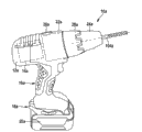
Fig. 1 has illustrated the hand-held tool that has by hammer mechanism of the present invention with stereogram;
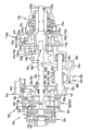
Fig. 2 shows the section by the hammer mechanism of Fig. 1;
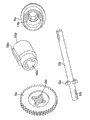
Fig. 3 individually shows the part of connector, hammer driving shaft, drift and the hammer of the hammer mechanism of Fig. 1 respectively in stereogram;
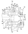
Fig. 4 is another part sectioned view of the hammer mechanism of Fig. 1, and it shows the impact generation cutting unit of hammer mechanism;
Fig. 5 shows first kind of alternative embodiment of drift of the hammer mechanism of Fig. 1 in the diagram;
Fig. 6 shows second kind of alternative embodiment of drift of the hammer mechanism of Fig. 1 in the diagram;
Fig. 7 there is shown the third alternative embodiment of drift of the hammer mechanism of Fig. 1 at section;
Fig. 8 there is shown the drift of Fig. 7 in first solid;
Fig. 9 there is shown the drift of Fig. 7 in second solid;
Figure 10 has illustrated the part of hammer of the hammer mechanism of Fig. 7 at stereogram; And
Figure 11 shows the 4th kind of alternative embodiment of drift of the hammer mechanism of Fig. 1 in the diagram.
The specific embodiment
Fig. 1 shows the hand-held tool 10a that is configured to the percussion drill driver.Hand-held tool 10a has pistol-like housing 12a.In housing 12a, arranging the CD-ROM drive motor 14a of hand-held tool 10a.Housing 12a has handle area 16a and battery connector 18a, the battery connector be arranged in handle area 16a on the end of CD-ROM drive motor 14a.Battery connector 18a can connect hand-held tool battery 20a with machinery discretely with the operator is electric.Hand-held tool battery 20a has 10.8 volts working voltage, but also can have other especially higher working voltage.In addition, hand-held tool 10a has by hammer mechanism 22a of the present invention, and hammer mechanism has hammer 24a and executive component 26a, the 28a that is arranged in the outside.
Fig. 2 there is shown hammer mechanism 22a at section.Hammer mechanism 22a comprises a planetary transmission 30a and hammer driving shaft 32a in addition.Planetary transmission 30a driven tool chuck driving shaft 32a when operation rotates around rotation.For this reason, planetary transmission 30a has three planetary gear gear stage 34a, 36a, 38a.Planetary transmission 30a can the person of being operated adjust in the two-stage at least at rotor 40a and the gearratio between the hammer driving shaft 32a of CD-ROM drive motor 14a.As alternative, the gearratio between CD-ROM drive motor 14a and hammer driving shaft 32a also can be regulated.
Hammer mechanism 22a has torque limiting apparatus 42a.Torque limiting apparatus 42a is maintained fixed the hollow wheel 44a of planetary transmission 30a in the course of the work.For this reason, torque limiting apparatus 42a has the fixedly ball 46a in some recesses that are engaged on hollow wheel 44a.The spring 48a of torque limiting apparatus 42a applies the power along the direction of hollow wheel 44a to fixing ball 46a for this reason.Can move by one of them executive component 26a by the operator along the fixing direction of ball 46a in the end that faces fixing ball 46a of spring 48a.For this reason, executive component 26a has eccentric element.Therefore the power that affacts on the fixing ball 46a can be adjusted.When reaching specific peak torque, fixedly ball 46a is extruded from recess and hollow wheel 44a idle running, interrupts the power transmission between rotor 40a and hammer driving shaft 32a thus.Therefore torque limiting apparatus 42a is provided for, and limits a maximum moment of torsion that can pass through hammer driving shaft 32a transmission.
Hammer mechanism 22a has the generating unit 50a of impact and the first connector 52a.The first connector 52a is connected with hammer driving shaft 32a antitorquely, or rather the first connector 52a and hammer driving shaft 32a integral type structure.Impact generating unit 50a and have the second connector 54a, second connector is connected with the first connector 52a in drill mode and/or percussive drilling pattern antitorquely.As shown in Figure 3, the first connector 52a is configured to forming part and the second connector 54a is configured to recess.When activating drill mode, the first connector 52a inserts the second connector 54a, inserts fully or rather.Therefore the connection between the first connector 52a and the second connector 54a can be removed along the moving axially of direction of hammer 24a by hammer driving shaft 32a.Between the first connector 52a and the second connector 54a, arranging the spring 56a of hammer mechanism 22a.Spring 56a is along the direction press tool chuck driving shaft 32a of hammer 24a.Spring is impacting the connection of having opened when generating unit 50a cuts off between the first connector 52a and the second connector 54a.
Hammer driving shaft 32a can support impactor 94a along impact direction 98a with moving.For this reason, impactor 94a limits the border of recess 100a.Hammer driving shaft 32a penetrates impactor 94a by recess 100a.At this, impactor 94a one perpendicular to the plane of recess 100a on 360 degree surround recess 100a.When operation, impactor 94a impacts on the drift 102a of hammer mechanism 22a.Drift 102a is arranged between insertion instrument 104a and the impactor 94a.Insertion instrument 104a is fixed among the hammer 24a under the state that is ready to move.Hammer 24a can be parallel to impact direction 98a motion ground supporting drift 102a.Drift 102a will pass to insertion instrument 104a from the shock pulse of impactor 94a when percussive drilling moves.
Hammer driving shaft 32a can be connected with drift 102a with axial motion and antitorquely.For this reason, drift 102a limits the border of recess 106a.Hammer driving shaft 32a is local being arranged among the recess 106a of drift 102a under the state of preparing operation.At this, hammer driving shaft 32a can support rotationally by drift 102a, hammer 24a and hammer bearing 70a.Hammer 24a is rotated formula at this by drift 102a and drives.For this reason, hammer 24a and drift 102a have each connector 108a, a 110a, and wherein, these connectors are provided for rotational motion is passed to hammer 24a.The connector 108a structure grooving of drift 102a, the main extension of groove is parallel to impact direction 98a and arranges.Connector 108a extends along the radially external surface of drift 102a.The connector 110a of hammer 24a is configured to the projection adaptive with groove.
Hammer 24a has insertion instrument attachment areas 112a, in this zone, insert instrument 104a the boring operation or screw in service along impact direction 98a regularly or percussive drilling is in service can be fastening along the impact direction 98a ground that moves.For this reason, hammer has contraction flow region 114a, and it limits the border of the moving region of drift 102a along impact direction.In addition, hammer 24a has dead ring 116a, and itself and impact direction 98a define the border of the moving region of drift 102a on the contrary.
In the percussive drilling process, the operator will insert instrument 104a and push towards the workpiece that is not shown specifically.The relative housing 12a of operator that is to say along the direction of CD-ROM drive motor 14a and moves insertion instrument 104a, drift 102a and hammer driving shaft 32a along a direction opposite with impact direction 98a thus.At this, the operator pushes the spring 56a of hammer mechanism 22a.The first connector 52a inserts the second connector 54a, and hammer driving shaft 32a begins to drive impact generating unit 50a thus.When the operator stopped that insertion instrument 104a pressed to workpiece, spring 56a was along impact direction 98a Move tool chuck driving shaft 32a, drift 102a and the instrument of insertion 104a.Therefore the antitorque connection that Open from This Side between the first connector 52a and the second connector 54a has cut off impact generating unit 50a.
Hammer mechanism 22a has the generation of impact cutting unit 118a, and it has locking element 120a, chute guiding device 122a and executive component 28a.Boring or screw in the pattern, locking element 120a causes a power that affacts drift 102a, this power be parallel to hammer driving shaft 32a at least one power affact on the drift 102a.The power of locking element 120a is by hammer bearing 70a, affact on the drift 102a by hammer 24a and by dead ring 116a.By the power of locking element 120a, at drill mode or screw in the pattern, prevented moving axially and thereby having prevented to impact the activation of generating unit 50a of drift 102a and hammer driving shaft 32a.The power of hammer driving shaft 32a has one according to the parallel component of effect, and this component drives drift 102a rotationally when operation.In addition, power has one according to effect and according to the parallel component of direction, and spring 56a affacts this component on the drift 102a by hammer driving shaft 32a.
Figure 4 illustrates one perpendicular to the section section of Fig. 2 and that be parallel to impact direction 98a orientation, wherein, executive component 28a is arranged in two different positions in Fig. 2 and 4 section.Executive component 28a is configured to annular.Executive component surrounds the rotation of hammer driving shaft 32a, and is coaxial or rather.Executive component 28a can be supported rotationally.Executive component is connected with chute guiding device 122a antitorquely.Chute guiding device 122a is configured to annular equally.Chute guiding device 122a has inclined-plane 124a.Inclined-plane 124a couples together two face 126a, the 128a of chute guiding device 122a.Face 126a, 128a are orientated perpendicular to impact direction 98a.Face 126a, 128a are arranged on the different planes along impact direction 98a.
In the percussive drilling pattern, locking element 120a is arranged among the recess 130a, and recess is in addition by inclined-plane 124a and one of them face 126a gauge.This face 126a arranges more near CD-ROM drive motor 14a than another face 128a.Housing 12a has casing member 132a, the antitorque ground of casing member and can support locking element movably along impact direction 98a.Therefore locking element 120a can be pressed towards a direction opposite with impact direction 98a when the percussive drilling process begins together with hammer 24a.In the percussive drilling process, locking element 120a does not act on any stopping power to hammer 24a.When impacting the executive component 28a rotation that cutting unit 118a takes place, locking element 120a moves through inclined-plane 124a along impact direction 98a.Locking element 120a is at drill mode or screw and be maintained in the pattern in this anterior position.Locking element 120a prevents that thus hammer driving shaft 32a is at drill mode or screw in the pattern axially and move.
Other embodiments of the invention have been shown in Fig. 5 to 11.Ensuing explanation and accompanying drawing are limited to the difference between these embodiment basically, wherein, the member that title is identical, the especially member that marks with identical Reference numeral, in principle also can be with reference to the accompanying drawings and/or to other embodiment, the particularly explanation of Fig. 1 to 4.In order to distinguish these embodiment, alphabetical a is the Reference numeral of the embodiment among Fig. 1 to 4.In the embodiment of Fig. 5 to 11, alphabetical a substitutes with alphabetical b to e.
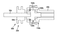
Fig. 5 shows the part of hammer mechanism 22b.The impactor 94b of the impact generating unit 50b of hammer mechanism 22b can be bearing on the hammer driving shaft 32b of hammer mechanism 22b with moving.Drift 102b has connector 108b, and this connector has formed antitorque being connected with the hammer 24b of hammer mechanism 22b at least one running status.Connector 108b is arranged on the side of the contraction flow region 114b that faces hammer 24b.Connector 108b is configured to make tooth portion.The sealing area 134b of drift does not abut in hammer 24b with making tooth and goes up and advantageously prevented dust intrusion impact generating unit 50b.
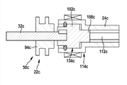
Fig. 6 schematically shows the part of hammer mechanism 22c as shown in Figure 5.The impactor 94c of the impact generating unit 50c of hammer mechanism 22c can be bearing on the hammer driving shaft 32c of hammer mechanism 22c with moving.Hammer driving shaft 32c can move axially ground and antitorque be connected with the drift 102c of hammer mechanism 22c.Drift 102c has connector 108c, and this connector has formed antitorque being connected with the hammer 24c of hammer mechanism 22c at least one running status.Hammer 24c has insertion instrument attachment areas 112c, and the connector 108c of drift 102c is engaged in this insertion instrument attachment areas to small part.Insertion instrument attachment areas 112c is provided for, and when operation the power edge is circumferentially affacted on the insertion instrument.Connector 108c is arranged among the contraction flow region 114c of hammer 24c to small part in the state of preparing operation.Connector 108c is configured to outer hexagon.Outer hexagonal size correspondence has the size of the binary digit that is used to screw operation usually.The sealing area 134c of drift 102c does not abut in that hammer 24c goes up and manufactured place and prevented advantageously that dust from invading and impact generating unit 50c at an easy rate with making tooth.Especially can the loss of minimum lubrication fat.
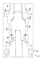
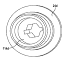
Fig. 7 to 10 illustrates as section equally and three-dimensional a part that shows hammer mechanism 22d.The impactor 94d of the impact generating unit 50d of hammer mechanism 22d can be bearing on the hammer driving shaft 32d of hammer mechanism 22d with moving.Hammer driving shaft 32d axially can be connected with the drift 102d of hammer mechanism 22d movably and antitorquely.Drift 102d has connector 108d, and connector has formed antitorque being connected with the hammer 24d of hammer mechanism 22d at least one running status.Connector 108d is arranged among the contraction flow region 114d of hammer 24d to small part in the state of preparing operation.Connector 108d is configured to have two system tooth portions about the opposed connection rib of rotation.Connector 108d has shape identical with the connector that is used for connecting with the insertion instrument and identical size.The corresponding standard SDS-Quick of shape and size.The sealing area 134d of drift 102d does not abut on the hammer 24d with making tooth.
Figure 11 schematically shows the part of hammer mechanism 22e as shown in Figure 5.The impactor 94e of the impact generating unit 50e of hammer mechanism 22e can be bearing on the hammer driving shaft 32e of hammer mechanism 22e with moving.Hammer driving shaft 32e is on axial restraint ground and antitorque be connected with the drift 102e of hammer mechanism 22e.Hammer driving shaft 32 and drift 102e integral type structure.When impacting, impactor 94e moves hammer driving shaft 32e and drift 102e together along impact direction 98e.Hammer driving shaft 32e by connector 62e axially can be movably and antitorquely be connected with the planetary gear gear stage that illustrates among the embodiment at Fig. 1 to 4.
Claims (11)
1. hammer mechanism, comprise at least one impact generating unit (50a-e), hammer driving shaft (32a-e), wherein impact generating unit (50a-e) and have column gear transmission level (72a), the rotating speed that this column gear transmission level is set for hammer driving shaft (32a-e) changes into the higher rotating speed that is used to produce impact.
2. by the described hammer mechanism of claim 1, it is characterized in that impact generating unit (50a-e) and have beater mechanism axle (78a), it is other that the rotation of this beater mechanism axle radially is arranged in hammer driving shaft (32a-e).
3. by the described hammer mechanism of claim 2, it is characterized in that, impact generating unit (50a-e) and have at least one bearing (80a) that this bearing is set for beater mechanism axle (78a) supporting regularly vertically.
4. by one of aforementioned claim described hammer mechanism, it is characterized in that, impact generating unit (50a-e) and have impactor (94a-e), hammer driving shaft (32a-e) can support impactor along impact direction (98a) at least a running status with moving.
5. by the described hammer mechanism of claim 4, it is characterized in that hammer driving shaft (32a-e) is partial penetration impactor (94a-e) at least.
6. by one of aforementioned claim described hammer mechanism, it is characterized in that being set for the bearing (60a) that hammer driving shaft (32a) can be supported vertically movably.
7. by one of aforementioned claim described hammer mechanism, it is characterized in that planetary transmission (30a), this planetary transmission is driven tool chuck driving shaft (32a) at least a running status.
8. by the described hammer mechanism of one of aforementioned claim, it is characterized in that hammer (24a) and have the drift (102a) of connector (108a) that this connector is set for rotational motion is delivered on the hammer (24a).
9. at least by the described hammer mechanism of claim 4, it is characterized in that being connected with hammer driving shaft (32a-e) antitorquely and being set for the connector (52a) that drives impact generating unit (50a-e).
10. at least by the described hammer mechanism of claim 8, it is characterized in that having the impact generation cutting unit (118a) of locking element (120a), this locking element affacts on the drift (102a) abreast at least one power of when operation boring and hammer driving shaft (32a) at least.
11. hand-held tool has by the described hammer mechanism of one of aforementioned claim.
Applications Claiming Priority (3)
| Application Number | Priority Date | Filing Date | Title |
|---|---|---|---|
| DE102010062094.7 | 2010-11-29 | ||
| DE102010062094A DE102010062094A1 (en) | 2010-11-29 | 2010-11-29 | Hammer mechanism |
| PCT/EP2011/067968 WO2012072327A1 (en) | 2010-11-29 | 2011-10-14 | Hammer percussion mechanism |
Publications (1)
| Publication Number | Publication Date |
|---|---|
| CN103221184A true CN103221184A (en) | 2013-07-24 |
Family
ID=44789489
Family Applications (1)
| Application Number | Title | Priority Date | Filing Date |
|---|---|---|---|
| CN201180057184XA Pending CN103221184A (en) | 2010-11-29 | 2011-10-14 | Hammer percussion mechanism |
Country Status (5)
| Country | Link |
|---|---|
| US (1) | US9636814B2 (en) |
| EP (1) | EP2646201B1 (en) |
| CN (1) | CN103221184A (en) |
| DE (1) | DE102010062094A1 (en) |
| WO (1) | WO2012072327A1 (en) |
Cited By (4)
| Publication number | Priority date | Publication date | Assignee | Title |
|---|---|---|---|---|
| CN107206578A (en) * | 2015-01-29 | 2017-09-26 | 罗伯特·博世有限公司 | Beater mechanism device, particularly for impact type screwdriver machine |
| CN109311145A (en) * | 2016-06-24 | 2019-02-05 | 喜利得股份公司 | Hand held power machine |
| CN113165151A (en) * | 2018-12-20 | 2021-07-23 | 喜利得股份公司 | Portable power tool |
| CN113966262A (en) * | 2019-09-06 | 2022-01-21 | 喜利得股份公司 | Hand-held power tool |
Families Citing this family (8)
| Publication number | Priority date | Publication date | Assignee | Title |
|---|---|---|---|---|
| CN101758486B (en) * | 2010-01-21 | 2011-09-28 | 浙江海王电器有限公司 | Light single-button multifunctional electric hammer |
| GB201112829D0 (en) * | 2011-07-26 | 2011-09-07 | Black & Decker Inc | Hammer |
| DE102011089913A1 (en) * | 2011-12-27 | 2013-06-27 | Robert Bosch Gmbh | Hand tool device |
| WO2014156471A1 (en) * | 2013-03-26 | 2014-10-02 | 日立工機株式会社 | Electric tool |
| US9539715B2 (en) * | 2014-01-16 | 2017-01-10 | Ingersoll-Rand Company | Controlled pivot impact tools |
| CN104153707B (en) * | 2014-08-18 | 2016-03-23 | 钟玉凤 | Hydraulic pressure cutting type percussive drill |
| US10328560B2 (en) * | 2015-02-23 | 2019-06-25 | Brian Romagnoli | Multi-mode drive mechanisms and tools incorporating the same |
| JP6638522B2 (en) * | 2015-08-07 | 2020-01-29 | 工機ホールディングス株式会社 | Electric tool |
Citations (5)
| Publication number | Priority date | Publication date | Assignee | Title |
|---|---|---|---|---|
| DE3611890A1 (en) * | 1985-12-17 | 1987-10-15 | Licentia Gmbh | Drive for the percussion mechanism of an electropneumatic rotary percussive hammer drill |
| DE4121279A1 (en) * | 1991-06-27 | 1993-01-07 | Bosch Gmbh Robert | DRILL AND / OR SLOPE |
| CN1704193A (en) * | 2004-06-02 | 2005-12-07 | 罗伯特·博世有限公司 | Hand operated machine tool especially hammer drill and/or percussion hammer |
| EP1834737A1 (en) * | 2006-03-18 | 2007-09-19 | Metabowerke GmbH | Electric hand tool |
| CN101253026A (en) * | 2005-08-31 | 2008-08-27 | 罗伯特·博世有限公司 | Drill hammer |
Family Cites Families (23)
| Publication number | Priority date | Publication date | Assignee | Title |
|---|---|---|---|---|
| US3203490A (en) * | 1963-06-27 | 1965-08-31 | Black & Decker Mfg Co | Compact rotary hammer |
| DE2449191C2 (en) * | 1974-10-16 | 1988-03-24 | Robert Bosch Gmbh, 7000 Stuttgart | hammer |
| US4325436A (en) * | 1980-05-21 | 1982-04-20 | Hilti Aktiengesellschaft | Hammer drill or chipping hammer device |
| JPS5969808U (en) * | 1982-09-07 | 1984-05-11 | 株式会社マキタ | Vibratory device in vibrating drill |
| NL8801466A (en) * | 1988-06-07 | 1990-01-02 | Emerson Electric Co | DEVICE FOR DRIVING A DRILL AND / OR IMPACT TOOL. |
| DE3931329C1 (en) * | 1989-05-31 | 1990-06-28 | Robert Bosch Gmbh, 7000 Stuttgart, De | |
| US5320177A (en) * | 1992-03-30 | 1994-06-14 | Makita Corporation | Power driven hammer drill |
| DE4231986A1 (en) * | 1992-09-24 | 1994-03-31 | Bosch Gmbh Robert | Hammer and / or percussion hammer |
| JPH08323520A (en) * | 1995-05-29 | 1996-12-10 | Makita Corp | Vibratory drill |
| DE19851888C1 (en) * | 1998-11-11 | 2000-07-13 | Metabowerke Kg | Hammer drill |
| JP3911905B2 (en) * | 1999-04-30 | 2007-05-09 | 松下電工株式会社 | Impact rotary tool |
| DE19955412A1 (en) * | 1999-11-18 | 2001-05-23 | Hilti Ag | Drilling and chiseling device |
| DE10136515C2 (en) * | 2001-07-26 | 2003-10-23 | Wacker Construction Equipment | Hammer and / or hammer with handle |
| GB0214772D0 (en) * | 2002-06-26 | 2002-08-07 | Black & Decker Inc | Hammer |
| JP2005052902A (en) * | 2003-08-06 | 2005-03-03 | Hitachi Koki Co Ltd | Vibrating drill |
| JP2005246831A (en) * | 2004-03-05 | 2005-09-15 | Hitachi Koki Co Ltd | Vibration drill |
| DE102004045117A1 (en) * | 2004-09-17 | 2006-03-23 | Robert Bosch Gmbh | switching device |
| EP1674213B1 (en) * | 2004-12-23 | 2008-10-01 | BLACK & DECKER INC. | Power tool cooling |
| US7410007B2 (en) * | 2005-09-13 | 2008-08-12 | Eastway Fair Company Limited | Impact rotary tool with drill mode |
| DE102005047600A1 (en) * | 2005-10-05 | 2007-04-12 | Robert Bosch Gmbh | Hand tool with a shaft and a mounted on the shaft Hubantriebslager |
| DE102009027442A1 (en) | 2009-07-03 | 2011-01-05 | Robert Bosch Gmbh | Hand tool |
| DE102009027440A1 (en) | 2009-07-03 | 2011-01-05 | Robert Bosch Gmbh | Hand tool |
| DE102009027444A1 (en) | 2009-07-03 | 2011-01-05 | Robert Bosch Gmbh | Hand tool |
-
2010
- 2010-11-29 DE DE102010062094A patent/DE102010062094A1/en not_active Withdrawn
-
2011
- 2011-10-14 EP EP11768040.5A patent/EP2646201B1/en active Active
- 2011-10-14 US US13/990,307 patent/US9636814B2/en active Active
- 2011-10-14 CN CN201180057184XA patent/CN103221184A/en active Pending
- 2011-10-14 WO PCT/EP2011/067968 patent/WO2012072327A1/en active Application Filing
Patent Citations (5)
| Publication number | Priority date | Publication date | Assignee | Title |
|---|---|---|---|---|
| DE3611890A1 (en) * | 1985-12-17 | 1987-10-15 | Licentia Gmbh | Drive for the percussion mechanism of an electropneumatic rotary percussive hammer drill |
| DE4121279A1 (en) * | 1991-06-27 | 1993-01-07 | Bosch Gmbh Robert | DRILL AND / OR SLOPE |
| CN1704193A (en) * | 2004-06-02 | 2005-12-07 | 罗伯特·博世有限公司 | Hand operated machine tool especially hammer drill and/or percussion hammer |
| CN101253026A (en) * | 2005-08-31 | 2008-08-27 | 罗伯特·博世有限公司 | Drill hammer |
| EP1834737A1 (en) * | 2006-03-18 | 2007-09-19 | Metabowerke GmbH | Electric hand tool |
Cited By (7)
| Publication number | Priority date | Publication date | Assignee | Title |
|---|---|---|---|---|
| CN107206578A (en) * | 2015-01-29 | 2017-09-26 | 罗伯特·博世有限公司 | Beater mechanism device, particularly for impact type screwdriver machine |
| CN107206578B (en) * | 2015-01-29 | 2020-06-23 | 罗伯特·博世有限公司 | Impact mechanism device, especially for impact screwdriver |
| US10870189B2 (en) | 2015-01-29 | 2020-12-22 | Robert Bosch Gmbh | Percussion mechanism device, in particular for an impact wrench |
| CN109311145A (en) * | 2016-06-24 | 2019-02-05 | 喜利得股份公司 | Hand held power machine |
| CN113165151A (en) * | 2018-12-20 | 2021-07-23 | 喜利得股份公司 | Portable power tool |
| CN113165151B (en) * | 2018-12-20 | 2024-04-23 | 喜利得股份公司 | Portable power tool |
| CN113966262A (en) * | 2019-09-06 | 2022-01-21 | 喜利得股份公司 | Hand-held power tool |
Also Published As
| Publication number | Publication date |
|---|---|
| WO2012072327A1 (en) | 2012-06-07 |
| EP2646201B1 (en) | 2014-08-06 |
| EP2646201A1 (en) | 2013-10-09 |
| DE102010062094A1 (en) | 2012-05-31 |
| US20130319709A1 (en) | 2013-12-05 |
| US9636814B2 (en) | 2017-05-02 |
Similar Documents
| Publication | Publication Date | Title |
|---|---|---|
| CN103221184A (en) | Hammer percussion mechanism | |
| EP1702723B1 (en) | Power tool torque overload clutch | |
| CN102476375A (en) | Hammer mechanism | |
| US6460627B1 (en) | Drilling and/or chiseling device | |
| CA1248782A (en) | Hammer drill with separate and interconnectable drive means | |
| US20090308626A1 (en) | Electric hand tool | |
| CN103182703B (en) | Hand tool device | |
| CN104023919B (en) | Hand tool device | |
| CN105058327A (en) | Multifunctional electric hammer structure | |
| CN103182549B (en) | Hand tool device | |
| CN103182547A (en) | Handheld tool device | |
| US7857074B2 (en) | Hand-held power tool with a percussion unit | |
| CN103221183A (en) | Hammer percussion mechanism | |
| CN104249335A (en) | Impact mechanism device | |
| CN103221185A (en) | Hammer mechanism | |
| CN103182548A (en) | Hand-held tool device | |
| US11969870B2 (en) | Portable power tool | |
| CN109562510A (en) | Accessories apparatus | |
| GB2472890A (en) | Device for generating an additional effect in a hand-held power tool | |
| JP6916819B2 (en) | Hand-held power tool device and hand-held power tool | |
| GB0625738D0 (en) | Hand-held power tool, in particular hammer drill and/or hammer chisel | |
| CN116507454A (en) | Power tool with two motors |
Legal Events
| Date | Code | Title | Description |
|---|---|---|---|
| C06 | Publication | ||
| PB01 | Publication | ||
| C10 | Entry into substantive examination | ||
| SE01 | Entry into force of request for substantive examination | ||
| C05 | Deemed withdrawal (patent law before 1993) | ||
| WD01 | Invention patent application deemed withdrawn after publication |
Application publication date: 20130724 |