CN102711684A - In-ear device with selectable frequency response - Google Patents
In-ear device with selectable frequency response Download PDFInfo
- Publication number
- CN102711684A CN102711684A CN2010800592428A CN201080059242A CN102711684A CN 102711684 A CN102711684 A CN 102711684A CN 2010800592428 A CN2010800592428 A CN 2010800592428A CN 201080059242 A CN201080059242 A CN 201080059242A CN 102711684 A CN102711684 A CN 102711684A
- Authority
- CN
- China
- Prior art keywords
- knob
- ear
- main body
- ear device
- wearer
- Prior art date
- Legal status (The legal status is an assumption and is not a legal conclusion. Google has not performed a legal analysis and makes no representation as to the accuracy of the status listed.)
- Granted
Links
Images


Classifications
-
- A—HUMAN NECESSITIES
- A61—MEDICAL OR VETERINARY SCIENCE; HYGIENE
- A61F—FILTERS IMPLANTABLE INTO BLOOD VESSELS; PROSTHESES; DEVICES PROVIDING PATENCY TO, OR PREVENTING COLLAPSING OF, TUBULAR STRUCTURES OF THE BODY, e.g. STENTS; ORTHOPAEDIC, NURSING OR CONTRACEPTIVE DEVICES; FOMENTATION; TREATMENT OR PROTECTION OF EYES OR EARS; BANDAGES, DRESSINGS OR ABSORBENT PADS; FIRST-AID KITS
- A61F11/00—Methods or devices for treatment of the ears or hearing sense; Non-electric hearing aids; Methods or devices for enabling ear patients to achieve auditory perception through physiological senses other than hearing sense; Protective devices for the ears, carried on the body or in the hand
- A61F11/06—Protective devices for the ears
- A61F11/08—Protective devices for the ears internal, e.g. earplugs
- A61F11/085—Protective devices for the ears internal, e.g. earplugs including an inner channel
Landscapes
- Health & Medical Sciences (AREA)
- Life Sciences & Earth Sciences (AREA)
- Biomedical Technology (AREA)
- Heart & Thoracic Surgery (AREA)
- Biophysics (AREA)
- Otolaryngology (AREA)
- Psychology (AREA)
- Engineering & Computer Science (AREA)
- Physics & Mathematics (AREA)
- Acoustics & Sound (AREA)
- Vascular Medicine (AREA)
- Animal Behavior & Ethology (AREA)
- General Health & Medical Sciences (AREA)
- Public Health (AREA)
- Veterinary Medicine (AREA)
- Headphones And Earphones (AREA)
- Respiratory Apparatuses And Protective Means (AREA)
Abstract
An in-ear device (1,1 ', 10O) comprises a main body (2) for placement in the outer ear of a wearer and has at least two derivative canals (24', 24'', 24''') each containing a filtering medium (25', 25'', 25''') differing from one another in terms of their frequency suppression capabilities, and a, preferably rotatable, knob (22,22') enabling selection of the respective filtering canal (24', 24'', 24''') without the need for removal of the device (1,1 ', 100) from the ear.
Description
Technical field
The present invention relates to the in ear device; For example internal ear hearing protectors (earplug), earphone or hearing assistance device; And or rather; Relate to and have the in ear device that selectable frequency response is arranged of determined value in advance, can under said device correctly is placed on wearer's the situation of in ear, make said selection.
Background technology
Especially it is considered to cause hearing impairment, and under extreme case, causes becoming deaf high-grade sound repeatedly.In different field such as military, commercial Application and music with in using, the hearing protectors that is used to reduce noise that has proposed to use many types is to avoid hearing impairment.
One of modal hearing protectors is a foam earplugs.Foam earplugs is compressed and inserts in the auditory meatus.When compression pressure interrupted, stopper opened to be fit to the internal structure of ear.A restriction of foam earplugs is that they are designed to the sound frequency of wide region is carried out filtering.If the wearer need protect the sound frequency of particular range-or the product that needs less decay when user when hearing sound or caution signals; He will have to remove earplug fully and put on a secondary new stopper of being processed by different materials, perhaps use passive or acoustically filtering initiatively.This process has a shortcoming, and user is not protected in the transition period.
A kind of ear protection device is arranged on the market, and it can be adjusted according to two different frequency response operator schemes.This device can switch between two different brackets of sound attenuating.; Because the cause of the rotary knob of (or around being substantially perpendicular to the planar axle of external ear) rotation in the plane of the axle that is arranged essentially parallel to the auditory meatus inlet; Need before changing to another kind of operator scheme, said device be removed from ear from a kind of operator scheme.This process also can make user not protected in the transition period.
Therefore, need a kind of in ear device of improvement, the wearer can be switched between the different brackets of decay protection, and do not damage his hearing conservation.
Summary of the invention
In order to overcome above-mentioned restriction and problem, main purpose of the present invention provides a kind of in ear device of improvement, and the wearer can be switched between the different brackets of sound protection, and does not damage his hearing conservation.
An advantage of the invention is provides a kind of in ear device, and it can optionally be adjusted and be used for the sound frequency of particular range or grade is carried out filtering.
Another advantage of the present invention provides a kind of in ear device; It via a rotary knob, pushing trigger button (push toggle button) or its analog or even its combination, allow the wearer to select attenuation degree or frequency range protection according to the sound condition of environment.
Another advantage of the present invention provides a kind of in ear device, need not remove this in ear device from wearer's in ear and just can adjust it like a cork.
Another advantage of the present invention provides a kind of in ear device; It can pass through adjustment; Make through on the in ear device, applying normal pressure and making device be inserted into wearer's in ear gradually naturally alternatively with rotatablely moving; Help said device to remain on wearer's in ear, especially when being pre-formed outthrust when being fit to auditory meatus.
According to an aspect of the present invention; A kind of in ear device is provided; Be used for optionally adjusting the scope or the grade of the sound frequency of the internal ear that arrives wearer's ear, therefore have selectable frequency response, said apparatus comprises having the main body on surface, the inside and outermost surfaces; A pipeline; In said main body and from the inside end on the surface, the inside of main body, extend to the outer end of outermost surfaces and be divided into contiguous outermost surfaces, circularize at least two pipelines of deriving in the zone basically what outermost surfaces defined, each above-mentioned pipeline is partially filled at least to have corresponding packing material; A knob; Preferably rotatably be attached to the outermost surfaces of main body and define and extend to outside the said interior zone to cover its peripheral edge of said interior zone; Above-mentioned knob is a passage of the interior formation of scope on surface within it; Said passage becomes the inside end in the adjacent rings zone that extends to knob radially from the knob periphery basically, and in a single day said thus knob rotates, and said passage just optionally is communicated with the corresponding said pipeline fluid of deriving.
Said knob is easily around coaxial with the axle of said annular region basically rotation axis rotation.
In addition, said knob is placed in the main body, and can rotate to from a position like a cork that another is external, and does not damage the filter capacity of said device.Generally speaking, device of the present invention has three different positions, and a kind of filter patterns to the type of the particular range of sound frequency or grade or sound is represented in each position.Said knob can rotate to another position from a position like a cork, and need not remove said device from ear.In addition, knob of the present invention comprises to the wearer and shows that knob correctly is positioned at the member in one of them position.
Usually, said main body has at least three sides, and above-mentioned at least three lateral first lateral shapes are fit to the tragus of wearer's ear, and above-mentioned at least three lateral second lateral shapes are fit to the antitragus of wearer's ear.
In an embodiment, said knob is the pushing trigger button, and it is placed on the outermost surfaces of main body movably.
In view of detailed description, will be appreciated that these and other advantages and purpose below in conjunction with accompanying drawing.
Description of drawings
The description that reference is associated with following accompanying drawing will be understood others of the present invention and advantage better, the similar assembly of similar referential expression that uses in the different drawings in the following accompanying drawing, wherein:
Fig. 1 is the perspective view according to an embodiment of main body of the present invention;
Fig. 2 is the perspective view according to another embodiment of main body of the present invention;
Fig. 3 is the perspective view according to the device of one embodiment of the present invention;
Fig. 4 a is the perspective view of the said embodiment of Fig. 3, has wherein omitted knob, to impel main intravital vividerization of element;
Fig. 4 b is the front view of the said embodiment of Fig. 4 a;
Fig. 5 is the side cutaway view on the circuit 5-5 among Fig. 3, has described the surrounding of knob when operation on filter patterns I;
Fig. 6 a is the perspective view of an embodiment, and wherein main body only has two pipelines of deriving;
Fig. 6 b is the front view of the said embodiment of Fig. 6 a;
Fig. 7 is the front view of the device of Fig. 1 in ear final position, wearer left side; And
Fig. 8 is the side view according to another embodiment of main body of the present invention that is similar to Fig. 5, is depicted as the pushing trigger button.
The specific embodiment
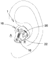
Illustrated in figures 1 and 2 is device 1 of the present invention, and it comprises main body 2.Generally speaking, main body 2 can and be shaped through design, thereby is placed on the outer in ear of specific wearer's ear safely.Illustrated in figures 1 and 2 is according to two of main body 2 of the present invention possible embodiment.Fig. 1 representes the shape that main body 2 is more general, and Fig. 2 representes to comprise an embodiment who is designed to insert the outthrust 20' in wearer's auditory meatus.
With reference to Fig. 3, be depicted as a specific embodiment of the present invention, comprise main body 2 with three sides 4,6 and 8.Each side of main body 2 is equal to each other basically, forms the similar leg-of-mutton main body 2 of shape.As an example, and be not restriction, three sides 4,6 and 8 of main body 2 are protruding, but they also can be configured as other geometries of picture.Device 1 can have at least three sides, and prerequisite is said lateral at least two designs and is shaped so that first side 6 is fit to the tragus A of wearer's ear, and second side 4 is fit to the antitragus B (see figure 7) of wearer's ear.Main body 2 also comprises at least three tips.As shown in Figure 3, two adjacent side combine through one in the tip 10,12 or 14.Most advanced and sophisticated 10,12 and 14 can have any geometry, and preferred most advanced and sophisticated 10,12 and 14 is circular.As shown in Figure 3, main body 2 comprises outermost surfaces 16 and surface, the inside 18.Outermost surfaces 16 can comprise the labelling that is illustrated in applicable filter patterns on the device 1.Main body 2 can have at least two filter patterns, and as reference, device 1 comprises filter patterns I, II and III in Fig. 3.
With reference to Fig. 4 a, be depicted as the pipeline 24 in main body 2.Pipeline 24 extends to the outer end of outermost surfaces 16 from the inside end on surface, the inside 18.Before arriving the outer end of outermost surfaces 16, pipeline 24 be divided into contiguous said outermost surfaces, on outermost surfaces, define circularize at least two pipelines of deriving in the zone 50 basically.Generally speaking; Derive the quantity of pipeline by the quantity decision of the filter patterns that can on device 1, use; Fig. 4 a and 4b are depicted as device 1 and comprise three filter patterns I, II and III, therefore comprise three relevant with filter patterns I, II and III respectively pipeline 24', 24 that derive " with 24 " '.The inside of each pipeline 24', 24 that derives " with 24 " ' is partially filled at least to have the corresponding filtering material 25', 25 " with 25 " ' that is used for the sound frequency of particular range or grade is carried out filtering especially; For example confirm the foam stopper of density in advance for corresponding required frequency response, the material formation makes and can only let the sound frequency of particular range or grade pass through.The pipeline 24', 24 " with 24 " ' that derives can be full of the filtering material fully, and more preferably, the pipeline 24', 24 that derives " with 24 " ' is partially filled.Generally speaking, each pipeline 24', 24 that derives " with 24 " ' fills with material different.About the filter capacity of pattern I, II and III depends on corresponding filtering material 25', 25 " with 25 " '.As an example, and be not restriction, filtering material 25', 25 " with 25 " ' can be through selecting, thereby all frequencies beyond people's the sound frequency have been carried out filtering, or the frequency relevant with impulsive noise carried out filtering.Filtering material 25', 25 " with 25 " ' can select from following various materials; Such as but not limited to following material: solid or porosu solid (metal or plastic foam), plastic layer or metallic sieve (Knowles Electronics's antivibrator); The wave filter of design (like customization ISL wave filter-expansion chamber or analog) suitably by the Institut Saint-Louis of France design, with and any combination.The extreme position of the pipeline 24', 24 that derives on outermost surfaces 16 " with 24 " ' makes that they are equidistant to annular regional 50 center basically.Such as hereinafter explanation, annular region 50 defines an interior zone for the rotation of knob 22.
With reference to Fig. 6 a and 6b, an extra embodiment of the present invention is arranged, drawing apparatus 100, wherein one of filtering position is designed to block basically all sound frequencies.The result has the inherent attenuation characteristic of the device 100 of filtering position according in ear device 100, stops sound to get into wearer's internal ear basically.In this embodiment, 100 in said device have two pipelines 24 of deriving " with 24 " '.Omitted derive pipeline 24' and its corresponding space and taken by the material of main body 2, the knob 22 that is used in correspondence position has been made the obstacle that sound gets into from opening 28.
Existing with reference to Fig. 8; Be depicted as 1' according to another embodiment of the present invention; Wherein knob 22' is the pushing trigger button that is placed in the outermost surfaces 16 of main body 2 movably; Under the normal pressure that the external strength that wearer's finger F of drawing with dotted line is represented applies, between available filter patterns, switch.
Although with to a certain degree characteristic description the present invention, only should understand and make announcement, and the present invention is not limited to this paper and describes the characteristic with illustrated example through the mode of instance, comprise that institute in the scope of the invention that preceding text advocate changes and revises.
Claims (18)
1. an in ear device (1,1', 100); Be used for optionally adjusting the scope or the grade of the sound frequency of the internal ear that arrives wearer's ear; Said apparatus (1,1', 100) comprises having the main body (2) on surface, the inside (18) and outermost surfaces (16); Pipeline (24) extends to the outer end of said outermost surfaces (16) and is divided into contiguous said outermost surfaces (18), circularizes at least two pipelines of deriving in the zone (50) (24', 24 "; 24 " ') basically what outermost surfaces defined in said main body (2) and from the said inside end on surface, the inside (18) of said main body (2); Each above-mentioned pipeline (24', 24 ", 24 " ') is partially filled at least to have corresponding filtering material (25'; 25 ", 25 " '); A knob (22; 22'), be attached to the said outermost surfaces (16) of said main body (2) and define and extend to the outer peripheral edge of said interior zone (50), above-mentioned knob (22 with the knob that covers said interior zone (50); 22') form a passage (30) in the scope on surface within it; Above-mentioned passage (30) becomes the inside end of the knob that extends to contiguous said annular region (50) radially from said knob periphery basically, and in a single day said thus knob rotates, said passage (30) just optionally with the corresponding above-mentioned pipeline (24' that derives; 24 ", 24 " ') the fluid connection.
2. in ear device according to claim 1 (1,100), wherein said knob (22) rotatably is attached to said outermost surfaces (16), is used for around coaxial with the axle of said annular region (50) basically rotation axis (40) rotation.
3. in ear device according to claim 2 (1,100), wherein said knob (22) can be around coaxial with the axle of said annular region (50) basically rotation axis (40) rotation.
4. in ear device according to claim 3 (1,100), wherein said knob (22) can around said axle (40) corresponding to the said pipeline of deriving (24', 24 " ,'s 24 " ') filtering position (I, II, III) between rotation.
5. in ear device according to claim 4 (1,100), wherein said knob (22) are placed in the main body (2); Make in use; Said knob (22) is suitable for from above-mentioned position that (I, II one of III) rotate to another position; And do not damage the filter capacity of said device (1,100).
6. in ear device according to claim 5 (1,100), wherein said device (1; 100) have at least two different filtering positions (I, II, III); (III) representative is to particular range or the sound frequency of grade or a filter patterns of sound type for I, II in each position.
7. in ear device according to claim 6 (1,100), wherein said device (1,100) have three filtering positions (I, II, II).
8. in ear device according to claim 4 (1,100), wherein said knob (22) are suitable for that (I, II II) rotate to another position, and do not need in use from ear, to remove said device (1,100) from a filtering position.
9. in ear device according to claim 4 (1,100), wherein said knob (22) but transposition get into said filtering position corresponding to the said pipeline of deriving (24', 24 ", 24 " ') (I, II, III).
10. in ear device according to claim 4 (1,100), wherein said knob (22) comprise member (22a, 22b, 22c), this member to the wearer show said knob (22) correctly be positioned at said filtering position (I, II, one of III) in.
11. in ear device according to claim 4 (1,100), wherein, (direction of rotation of said knob (22) III) is the ear that will place according to said device (1,100) and confirming in advance for I, II to change said filtering position.
12. in ear device according to claim 11 (1,100), wherein above-mentioned predetermined direction of rotation are deployed in the relevant in ear of wearer with assisting in ensuring that said device (1,100) continuous and effective.
13. in ear device (1 according to claim 1; 100); Wherein said main body (2) has at least three sides (4,6,8); Above-mentioned at least three lateral first sides (6) are shaped with the tragus (A) of suitable wearer's ear, and above-mentioned at least three lateral second sides (4) are shaped to be fit to the antitragus (B) of wearer's ear.
14. in ear device according to claim 13 (1,100), possess on the wherein said main body (2) member (22a, 22b, 22c), to show the said pipeline of deriving (24', 24 " ,'s 24 " ') position.
15. in ear device according to claim 2 (100); Wherein said main body (2) is suitable for providing the pipeline of deriving (24') of blockade; In case in use select through the rotation of said knob (22) thus, all basically sound frequencies are stoped to the propagation of the wearer's ear inherent attenuation characteristic through said in ear device (100).
16. in ear device according to claim 2 (1,100), wherein said main body (2) possesses an outthrust (20'), is suitable for inserting in wearer's the auditory meatus.
17. being configured as in advance, in ear device according to claim 16 (1,100), wherein said outthrust (20') be fit to insert in wearer's the auditory meatus.
18. in ear device according to claim 1 (1'), wherein said knob (22') are the pushing trigger buttons that is placed in the said outermost surfaces (16) of said main body (2) movably.
Applications Claiming Priority (3)
| Application Number | Priority Date | Filing Date | Title |
|---|---|---|---|
| US28217609P | 2009-12-24 | 2009-12-24 | |
| US61/282,176 | 2009-12-24 | ||
| PCT/CA2010/002044 WO2011075840A1 (en) | 2009-12-24 | 2010-12-24 | In-ear device with selectable frequency response |
Publications (2)
| Publication Number | Publication Date |
|---|---|
| CN102711684A true CN102711684A (en) | 2012-10-03 |
| CN102711684B CN102711684B (en) | 2014-04-09 |
Family
ID=44187602
Family Applications (1)
| Application Number | Title | Priority Date | Filing Date |
|---|---|---|---|
| CN201080059242.8A Expired - Fee Related CN102711684B (en) | 2009-12-24 | 2010-12-24 | In-ear device with selectable frequency response |
Country Status (8)
| Country | Link |
|---|---|
| US (1) | US8903114B2 (en) |
| EP (1) | EP2533739A4 (en) |
| JP (1) | JP2013515515A (en) |
| CN (1) | CN102711684B (en) |
| AU (1) | AU2010335987B2 (en) |
| CA (1) | CA2785579A1 (en) |
| WO (1) | WO2011075840A1 (en) |
| ZA (1) | ZA201205465B (en) |
Cited By (1)
| Publication number | Priority date | Publication date | Assignee | Title |
|---|---|---|---|---|
| CN107113518A (en) * | 2015-01-19 | 2017-08-29 | 3M创新有限公司 | Hearing protection with helical form horn |
Families Citing this family (14)
| Publication number | Priority date | Publication date | Assignee | Title |
|---|---|---|---|---|
| FR2997010A1 (en) * | 2012-10-24 | 2014-04-25 | Michel Meziani | Auditory protection device for use on e.g. helmet, to protect auditory canal of ear of human being against noise, has filtering unit mounted to move in main body according to preset fixed positions corresponding to preset filtering level |
| US9814625B2 (en) | 2013-01-04 | 2017-11-14 | 3M Innovative Properties Company | Selective attenuating earplug |
| USD754323S1 (en) | 2014-02-17 | 2016-04-19 | 3M Innovative Properties Company | Hearing device retainer |
| USD733865S1 (en) | 2014-02-17 | 2015-07-07 | 3M Innovative Properties Company | Earplug switch |
| USD754324S1 (en) | 2014-02-17 | 2016-04-19 | 3M Innovative Properties Company | Hearing device retainer |
| FR3020274B1 (en) * | 2014-04-24 | 2016-04-15 | Zodiac Aerotechnics | REGULATING ASSEMBLY FOR RESPIRATORY MASK. |
| CN208548996U (en) * | 2015-02-10 | 2019-02-26 | 飞宗公司 | Wireless earbud |
| US20170281416A1 (en) * | 2016-04-04 | 2017-10-05 | MDideaFactory | Apparatus and methods for ear protection and enhancement |
| NL2017626B1 (en) * | 2016-10-14 | 2018-04-24 | Teake De Jong Arjen | ADJUSTABLE HEARING PROTECTION DEVICE |
| USD832823S1 (en) * | 2017-04-05 | 2018-11-06 | Shenzhen Zijieyuanzi Technology Co., ltd. | Wireless earset |
| US11246755B2 (en) | 2017-11-17 | 2022-02-15 | Microsonic, Inc. | Sound attenuation earplug system and method of manufacture |
| SE542109C2 (en) * | 2018-04-04 | 2020-02-25 | Ear Labs Ab | An earplug for selective attenuation of sound and an insert with an acoustic filter for use in an earplug |
| US11707380B2 (en) | 2019-04-15 | 2023-07-25 | Mdideafactory, Inc. | Ear apparatus and methods of use |
| FR3134963B1 (en) * | 2022-04-27 | 2024-04-12 | Scorpion | DEVICE FOR SELECTIVE ATTENUATION OF NOISE EMITTED BY DENTISTRY EQUIPMENT |
Citations (5)
| Publication number | Priority date | Publication date | Assignee | Title |
|---|---|---|---|---|
| GB1276498A (en) * | 1968-08-01 | 1972-06-01 | Amplivox Ltd | Improvements in and relating to ear defenders |
| US20030196850A1 (en) * | 2002-04-18 | 2003-10-23 | Jabra Corporation | Earmold for improved retention of coupled device |
| CN2870792Y (en) * | 2006-02-24 | 2007-02-21 | 张民 | High and low noise filtering earphone |
| US7182087B1 (en) * | 2001-10-26 | 2007-02-27 | Marsh Robert E | Dual position hearing protection device |
| US7478702B2 (en) * | 2004-08-25 | 2009-01-20 | Phonak Ag | Customized hearing protection earplug and method for manufacturing the same |
Family Cites Families (13)
| Publication number | Priority date | Publication date | Assignee | Title |
|---|---|---|---|---|
| US1276498A (en) * | 1917-10-04 | 1918-08-20 | John W Curran | Waste-container. |
| US3637040A (en) | 1968-08-01 | 1972-01-25 | Amplivox Ltd | Ear defenders |
| FR2657716B1 (en) * | 1990-02-01 | 1995-07-13 | Leher Francois | SOUND TRANSMISSION DEVICE WITH SELECTIVE FILTERING, INTENDED TO BE PLACED IN THE EXTERNAL AUDITIVE DUCT. |
| IL163756A0 (en) * | 1997-05-30 | 2005-12-18 | Qualcomm Inc | A method of and apparatus for paging a wireless terminal in a wireless telecommunications system |
| CA2318188A1 (en) * | 1998-01-19 | 1999-07-22 | Simply Silence Simsin B.V. | Hearing protector |
| US6228233B1 (en) * | 1998-11-30 | 2001-05-08 | Applied Materials, Inc. | Inflatable compliant bladder assembly |
| GB9907050D0 (en) | 1999-03-26 | 1999-05-19 | Sonomax Sft Inc | System for fitting a hearing device in the ear |
| US6082485A (en) * | 1999-08-10 | 2000-07-04 | Smith; Eric B. | Adjustable earplug |
| US6687377B2 (en) | 2000-12-20 | 2004-02-03 | Sonomax Hearing Healthcare Inc. | Method and apparatus for determining in situ the acoustic seal provided by an in-ear device |
| US20020114479A1 (en) | 2001-02-20 | 2002-08-22 | Mcintoch Ian | Expandable in-ear device |
| EP1498092A1 (en) * | 2003-07-14 | 2005-01-19 | Ruth Poissenot | Hearing protection |
| PL1702497T3 (en) | 2003-12-05 | 2016-04-29 | 3M Innovative Properties Co | Method and apparatus for objective assessment of in-ear device acoustical performance |
| EP1629809A1 (en) * | 2004-08-25 | 2006-03-01 | Phonak Ag | Customized hearing protection earplug and method for manufacturing the same |
-
2010
- 2010-12-24 CA CA2785579A patent/CA2785579A1/en not_active Abandoned
- 2010-12-24 CN CN201080059242.8A patent/CN102711684B/en not_active Expired - Fee Related
- 2010-12-24 WO PCT/CA2010/002044 patent/WO2011075840A1/en active Application Filing
- 2010-12-24 EP EP10838473.6A patent/EP2533739A4/en not_active Withdrawn
- 2010-12-24 JP JP2012545035A patent/JP2013515515A/en active Pending
- 2010-12-24 AU AU2010335987A patent/AU2010335987B2/en not_active Ceased
- 2010-12-27 US US12/929,052 patent/US8903114B2/en not_active Expired - Fee Related
-
2012
- 2012-07-18 ZA ZA2012/05465A patent/ZA201205465B/en unknown
Patent Citations (5)
| Publication number | Priority date | Publication date | Assignee | Title |
|---|---|---|---|---|
| GB1276498A (en) * | 1968-08-01 | 1972-06-01 | Amplivox Ltd | Improvements in and relating to ear defenders |
| US7182087B1 (en) * | 2001-10-26 | 2007-02-27 | Marsh Robert E | Dual position hearing protection device |
| US20030196850A1 (en) * | 2002-04-18 | 2003-10-23 | Jabra Corporation | Earmold for improved retention of coupled device |
| US7478702B2 (en) * | 2004-08-25 | 2009-01-20 | Phonak Ag | Customized hearing protection earplug and method for manufacturing the same |
| CN2870792Y (en) * | 2006-02-24 | 2007-02-21 | 张民 | High and low noise filtering earphone |
Cited By (2)
| Publication number | Priority date | Publication date | Assignee | Title |
|---|---|---|---|---|
| CN107113518A (en) * | 2015-01-19 | 2017-08-29 | 3M创新有限公司 | Hearing protection with helical form horn |
| CN107113518B (en) * | 2015-01-19 | 2020-06-23 | 3M创新有限公司 | Hearing protection device with spiral acoustic horn |
Also Published As
| Publication number | Publication date |
|---|---|
| US20110158421A1 (en) | 2011-06-30 |
| CN102711684B (en) | 2014-04-09 |
| JP2013515515A (en) | 2013-05-09 |
| WO2011075840A9 (en) | 2011-09-01 |
| US8903114B2 (en) | 2014-12-02 |
| AU2010335987A1 (en) | 2012-08-09 |
| CA2785579A1 (en) | 2011-06-30 |
| ZA201205465B (en) | 2015-01-28 |
| EP2533739A1 (en) | 2012-12-19 |
| WO2011075840A1 (en) | 2011-06-30 |
| EP2533739A4 (en) | 2013-09-04 |
| AU2010335987B2 (en) | 2015-11-12 |
Similar Documents
| Publication | Publication Date | Title |
|---|---|---|
| CN102711684A (en) | In-ear device with selectable frequency response | |
| US7783056B2 (en) | Earplug | |
| KR101545087B1 (en) | Earplug and earplug set having the same | |
| EP2941229B1 (en) | Selective attenuating earplug | |
| EP0287315A2 (en) | Ear wax barriers for hearing aids | |
| WO2005041830A3 (en) | Low sound attenuating hearing protection device | |
| US7025061B2 (en) | Customized passive hearing protection earplug, use of the same and method for manufacturing the same | |
| WO2017023634A1 (en) | Noise reduction with in-ear headphone | |
| US10484772B2 (en) | Hidden rear cavity vent | |
| US10779992B2 (en) | Hearing protection devices and attenuation button for same | |
| US11266531B2 (en) | Device for protecting the human sensory hearing system while retaining quality sound | |
| US20060042867A1 (en) | Hearing protection earplug and method for manufacturing such an earplug | |
| JP2004507194A (en) | hearing aid | |
| EP1629806B1 (en) | Hearing protection earplug and method for manufacturing such an earplug | |
| WO2020180901A1 (en) | Vented sound attenuation earplug system | |
| DE102010015771B4 (en) | Ear protection with adjustable damping | |
| EP2515811B1 (en) | Ear protector with an acoustic damping filter for hearing protection as well as filter housing for such an ear protector | |
| KR200297593Y1 (en) | Noise-excluding earplug | |
| KR200276640Y1 (en) | Noise-excluding earplug | |
| NL1039885C2 (en) | Sound damping ear protector, with a universal fitting. | |
| EP1629803A1 (en) | Customized passive hearing protection earplug, use of the same and method for manufacturing the same |
Legal Events
| Date | Code | Title | Description |
|---|---|---|---|
| C06 | Publication | ||
| PB01 | Publication | ||
| C10 | Entry into substantive examination | ||
| SE01 | Entry into force of request for substantive examination | ||
| C14 | Grant of patent or utility model | ||
| GR01 | Patent grant | ||
| CF01 | Termination of patent right due to non-payment of annual fee |
Granted publication date: 20140409 Termination date: 20141224 |
|
| EXPY | Termination of patent right or utility model |