CN102458282A - Variable angle screw plate systems - Google Patents
Variable angle screw plate systems Download PDFInfo
- Publication number
- CN102458282A CN102458282A CN2010800329061A CN201080032906A CN102458282A CN 102458282 A CN102458282 A CN 102458282A CN 2010800329061 A CN2010800329061 A CN 2010800329061A CN 201080032906 A CN201080032906 A CN 201080032906A CN 102458282 A CN102458282 A CN 102458282A
- Authority
- CN
- China
- Prior art keywords
- head
- opening
- bone fixation
- fixation element
- core
- Prior art date
- Legal status (The legal status is an assumption and is not a legal conclusion. Google has not performed a legal analysis and makes no representation as to the accuracy of the status listed.)
- Pending
Links
- 210000000988 bone and bone Anatomy 0.000 claims abstract description 101
- 238000002513 implantation Methods 0.000 claims description 13
- 238000003780 insertion Methods 0.000 claims description 12
- 230000037431 insertion Effects 0.000 claims description 12
- 239000000463 material Substances 0.000 claims description 10
- 238000000034 method Methods 0.000 claims description 9
- 238000005452 bending Methods 0.000 claims description 3
- 230000015572 biosynthetic process Effects 0.000 claims description 2
- 230000002093 peripheral effect Effects 0.000 claims 1
- 230000008878 coupling Effects 0.000 description 7
- 238000010168 coupling process Methods 0.000 description 7
- 238000005859 coupling reaction Methods 0.000 description 7
- 239000004696 Poly ether ether ketone Substances 0.000 description 3
- 229920002530 polyetherether ketone Polymers 0.000 description 3
- RTAQQCXQSZGOHL-UHFFFAOYSA-N Titanium Chemical compound [Ti] RTAQQCXQSZGOHL-UHFFFAOYSA-N 0.000 description 2
- 238000007373 indentation Methods 0.000 description 2
- 229910052719 titanium Inorganic materials 0.000 description 2
- 239000010936 titanium Substances 0.000 description 2
- LENZDBCJOHFCAS-UHFFFAOYSA-N tris Chemical compound OCC(N)(CO)CO LENZDBCJOHFCAS-UHFFFAOYSA-N 0.000 description 2
- 229910000831 Steel Inorganic materials 0.000 description 1
- 230000003321 amplification Effects 0.000 description 1
- 238000013459 approach Methods 0.000 description 1
- -1 cochrome Substances 0.000 description 1
- 125000004122 cyclic group Chemical group 0.000 description 1
- 238000013461 design Methods 0.000 description 1
- 238000005516 engineering process Methods 0.000 description 1
- 238000009434 installation Methods 0.000 description 1
- 230000013011 mating Effects 0.000 description 1
- 238000012986 modification Methods 0.000 description 1
- 230000004048 modification Effects 0.000 description 1
- 238000003199 nucleic acid amplification method Methods 0.000 description 1
- 239000004033 plastic Substances 0.000 description 1
- 229920003023 plastic Polymers 0.000 description 1
- 229920000570 polyether Polymers 0.000 description 1
- 239000010959 steel Substances 0.000 description 1
- 238000001356 surgical procedure Methods 0.000 description 1
Images


Classifications
-
- A—HUMAN NECESSITIES
- A61—MEDICAL OR VETERINARY SCIENCE; HYGIENE
- A61B—DIAGNOSIS; SURGERY; IDENTIFICATION
- A61B17/00—Surgical instruments, devices or methods, e.g. tourniquets
- A61B17/56—Surgical instruments or methods for treatment of bones or joints; Devices specially adapted therefor
- A61B17/58—Surgical instruments or methods for treatment of bones or joints; Devices specially adapted therefor for osteosynthesis, e.g. bone plates, screws, setting implements or the like
- A61B17/68—Internal fixation devices, including fasteners and spinal fixators, even if a part thereof projects from the skin
- A61B17/84—Fasteners therefor or fasteners being internal fixation devices
- A61B17/86—Pins or screws or threaded wires; nuts therefor
- A61B17/8605—Heads, i.e. proximal ends projecting from bone
-
- A—HUMAN NECESSITIES
- A61—MEDICAL OR VETERINARY SCIENCE; HYGIENE
- A61B—DIAGNOSIS; SURGERY; IDENTIFICATION
- A61B17/00—Surgical instruments, devices or methods, e.g. tourniquets
- A61B17/56—Surgical instruments or methods for treatment of bones or joints; Devices specially adapted therefor
- A61B17/58—Surgical instruments or methods for treatment of bones or joints; Devices specially adapted therefor for osteosynthesis, e.g. bone plates, screws, setting implements or the like
- A61B17/68—Internal fixation devices, including fasteners and spinal fixators, even if a part thereof projects from the skin
- A61B17/84—Fasteners therefor or fasteners being internal fixation devices
- A61B17/86—Pins or screws or threaded wires; nuts therefor
-
- A—HUMAN NECESSITIES
- A61—MEDICAL OR VETERINARY SCIENCE; HYGIENE
- A61B—DIAGNOSIS; SURGERY; IDENTIFICATION
- A61B17/00—Surgical instruments, devices or methods, e.g. tourniquets
- A61B17/56—Surgical instruments or methods for treatment of bones or joints; Devices specially adapted therefor
- A61B17/58—Surgical instruments or methods for treatment of bones or joints; Devices specially adapted therefor for osteosynthesis, e.g. bone plates, screws, setting implements or the like
- A61B17/68—Internal fixation devices, including fasteners and spinal fixators, even if a part thereof projects from the skin
- A61B17/80—Cortical plates, i.e. bone plates; Instruments for holding or positioning cortical plates, or for compressing bones attached to cortical plates
- A61B17/8033—Cortical plates, i.e. bone plates; Instruments for holding or positioning cortical plates, or for compressing bones attached to cortical plates having indirect contact with screw heads, or having contact with screw heads maintained with the aid of additional components, e.g. nuts, wedges or head covers
- A61B17/8047—Cortical plates, i.e. bone plates; Instruments for holding or positioning cortical plates, or for compressing bones attached to cortical plates having indirect contact with screw heads, or having contact with screw heads maintained with the aid of additional components, e.g. nuts, wedges or head covers wherein the additional element surrounds the screw head in the plate hole
-
- A—HUMAN NECESSITIES
- A61—MEDICAL OR VETERINARY SCIENCE; HYGIENE
- A61B—DIAGNOSIS; SURGERY; IDENTIFICATION
- A61B17/00—Surgical instruments, devices or methods, e.g. tourniquets
- A61B17/56—Surgical instruments or methods for treatment of bones or joints; Devices specially adapted therefor
- A61B17/58—Surgical instruments or methods for treatment of bones or joints; Devices specially adapted therefor for osteosynthesis, e.g. bone plates, screws, setting implements or the like
- A61B17/68—Internal fixation devices, including fasteners and spinal fixators, even if a part thereof projects from the skin
- A61B17/80—Cortical plates, i.e. bone plates; Instruments for holding or positioning cortical plates, or for compressing bones attached to cortical plates
- A61B17/8052—Cortical plates, i.e. bone plates; Instruments for holding or positioning cortical plates, or for compressing bones attached to cortical plates immobilised relative to screws by interlocking form of the heads and plate holes, e.g. conical or threaded
-
- A—HUMAN NECESSITIES
- A61—MEDICAL OR VETERINARY SCIENCE; HYGIENE
- A61B—DIAGNOSIS; SURGERY; IDENTIFICATION
- A61B17/00—Surgical instruments, devices or methods, e.g. tourniquets
- A61B17/56—Surgical instruments or methods for treatment of bones or joints; Devices specially adapted therefor
- A61B17/58—Surgical instruments or methods for treatment of bones or joints; Devices specially adapted therefor for osteosynthesis, e.g. bone plates, screws, setting implements or the like
- A61B17/68—Internal fixation devices, including fasteners and spinal fixators, even if a part thereof projects from the skin
- A61B17/84—Fasteners therefor or fasteners being internal fixation devices
- A61B17/86—Pins or screws or threaded wires; nuts therefor
- A61B17/8605—Heads, i.e. proximal ends projecting from bone
- A61B17/861—Heads, i.e. proximal ends projecting from bone specially shaped for gripping driver
- A61B17/8615—Heads, i.e. proximal ends projecting from bone specially shaped for gripping driver at the central region of the screw head
-
- A—HUMAN NECESSITIES
- A61—MEDICAL OR VETERINARY SCIENCE; HYGIENE
- A61B—DIAGNOSIS; SURGERY; IDENTIFICATION
- A61B17/00—Surgical instruments, devices or methods, e.g. tourniquets
- A61B17/56—Surgical instruments or methods for treatment of bones or joints; Devices specially adapted therefor
- A61B17/58—Surgical instruments or methods for treatment of bones or joints; Devices specially adapted therefor for osteosynthesis, e.g. bone plates, screws, setting implements or the like
- A61B17/88—Osteosynthesis instruments; Methods or means for implanting or extracting internal or external fixation devices
- A61B17/8875—Screwdrivers, spanners or wrenches
- A61B17/8886—Screwdrivers, spanners or wrenches holding the screw head
- A61B17/8888—Screwdrivers, spanners or wrenches holding the screw head at its central region
-
- A—HUMAN NECESSITIES
- A61—MEDICAL OR VETERINARY SCIENCE; HYGIENE
- A61B—DIAGNOSIS; SURGERY; IDENTIFICATION
- A61B17/00—Surgical instruments, devices or methods, e.g. tourniquets
- A61B17/56—Surgical instruments or methods for treatment of bones or joints; Devices specially adapted therefor
- A61B17/58—Surgical instruments or methods for treatment of bones or joints; Devices specially adapted therefor for osteosynthesis, e.g. bone plates, screws, setting implements or the like
- A61B17/88—Osteosynthesis instruments; Methods or means for implanting or extracting internal or external fixation devices
- A61B17/8875—Screwdrivers, spanners or wrenches
- A61B17/8894—Screwdrivers, spanners or wrenches holding the implant into or through which the screw is to be inserted
-
- A—HUMAN NECESSITIES
- A61—MEDICAL OR VETERINARY SCIENCE; HYGIENE
- A61B—DIAGNOSIS; SURGERY; IDENTIFICATION
- A61B17/00—Surgical instruments, devices or methods, e.g. tourniquets
- A61B17/56—Surgical instruments or methods for treatment of bones or joints; Devices specially adapted therefor
- A61B17/58—Surgical instruments or methods for treatment of bones or joints; Devices specially adapted therefor for osteosynthesis, e.g. bone plates, screws, setting implements or the like
- A61B17/68—Internal fixation devices, including fasteners and spinal fixators, even if a part thereof projects from the skin
- A61B17/84—Fasteners therefor or fasteners being internal fixation devices
- A61B17/86—Pins or screws or threaded wires; nuts therefor
- A61B17/866—Material or manufacture
-
- A—HUMAN NECESSITIES
- A61—MEDICAL OR VETERINARY SCIENCE; HYGIENE
- A61B—DIAGNOSIS; SURGERY; IDENTIFICATION
- A61B17/00—Surgical instruments, devices or methods, e.g. tourniquets
- A61B17/56—Surgical instruments or methods for treatment of bones or joints; Devices specially adapted therefor
- A61B17/58—Surgical instruments or methods for treatment of bones or joints; Devices specially adapted therefor for osteosynthesis, e.g. bone plates, screws, setting implements or the like
- A61B17/68—Internal fixation devices, including fasteners and spinal fixators, even if a part thereof projects from the skin
- A61B17/84—Fasteners therefor or fasteners being internal fixation devices
- A61B17/86—Pins or screws or threaded wires; nuts therefor
- A61B17/8685—Pins or screws or threaded wires; nuts therefor comprising multiple separate parts
Landscapes
- Health & Medical Sciences (AREA)
- Orthopedic Medicine & Surgery (AREA)
- Surgery (AREA)
- Life Sciences & Earth Sciences (AREA)
- Heart & Thoracic Surgery (AREA)
- Nuclear Medicine, Radiotherapy & Molecular Imaging (AREA)
- Engineering & Computer Science (AREA)
- Biomedical Technology (AREA)
- Medical Informatics (AREA)
- Molecular Biology (AREA)
- Animal Behavior & Ethology (AREA)
- General Health & Medical Sciences (AREA)
- Public Health (AREA)
- Veterinary Medicine (AREA)
- Neurology (AREA)
- Surgical Instruments (AREA)
Abstract
A bone fixation element comprises a shaft extending longitudinally from a proximal end to a distal end and a head connected to the proximal end of the shaft. The head includes a radially outer abutting structure deformable to lockingly engage an inner wall of an opening through a bone plate. Deformation of the abutting structure permits the head to lock the bone fixation element within the opening at any user-selected angle with respect to a central axis of the opening within a permitted range of angulation.
Description
Technical field
The application requires to submit on May 26th, 2009, name is called the 61/181st, No. 149 U.S. Provisional Application No. of " the screw plate system of variable-angle ", and the full content of this application is incorporated this paper by reference into.
Technical field
The application relates to the device that is used to handle fracture, and more specifically, relates to the device that is used for the implantation piece such as blade plate is fixed to skeleton.
Background technology
In specific bone surgery, usually need be with a plurality of skeletons or bone portion relative fixed.The various plate system that is used for the internal fixation of different skeletons is known.Such system generally includes: be connected to said skeleton or stride across fracture line or the plate of the bone portion of disc space.This plate generally includes a plurality of holes, inserts to engage following skeleton through this hole such as the retaining element of bone screw.Some plate systems comprise constraint screw or lock screw, and this constraint screw or lock screw are locked in the corresponding plate hole with fixed direction.Other plate system comprises semi-constrained screw or non-locking screw, and this semi-constrained screw or non-locking screw can move in plate hole or rotate.
Summary of the invention
The present invention is directed to a kind of bone fixation element; Comprise: axial region and head; Said axial region longitudinally extends to far-end from near-end; Said head is connected to the near-end of said axial region; Said head comprises: radial outer abutment structure, this abutment structure can be out of shape the inwall that engages the opening that passes blade plate with locking ground, and the distortion of said abutment structure allows said head selectes said bone fixation element in the angular range that allows about the central axis of said opening with any user angle locking in opening.
Description of drawings
Fig. 1 illustrates the axonometric chart first example embodiment, that insert the device of blade plate according to the present invention;
Fig. 2 illustrates side view Fig. 1, that insert the device of blade plate;
Fig. 3 illustrates the side view of the device of Fig. 1;
Fig. 4 illustrates the top view of the device of Fig. 1;
Fig. 5 illustrates the side cross-sectional view of amplification of head of the device of Fig. 1;
Fig. 6 illustrates according to cross-sectional perspective view second example embodiment of the present invention, that use the device of driven tool insertion blade plate;
Fig. 7 illustrates another cross-sectional perspective view Fig. 6, that use the device of driven tool insertion blade plate;
Fig. 8 illustrates cross-sectional perspective view Fig. 6, that use the device of driven tool insertion blade plate;
Fig. 9 illustrates the axonometric chart of the device of Fig. 6;
Figure 10 illustrates the side view of the device of Fig. 6;
Figure 11 illustrates the side cross-sectional view of the device of Fig. 6;
Figure 12 illustrates the top view of the device of Fig. 6;
Figure 13 illustrates the top view according to the device of another embodiment of the present invention;
Figure 14 illustrates according to axonometric chart the 3rd embodiment of the present invention, that insert the device of blade plate;
Figure 15 illustrates the side cross-sectional view of the device of Figure 14;
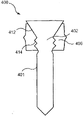
Figure 16 illustrates according to the screw of the device of Figure 14 or the axonometric chart of pin;
Figure 17 illustrates the screw of Figure 16 or the side view of pin;
Figure 18 illustrates the side cross-sectional view of screw or the pin of Figure 16;
Figure 19 illustrates the screw of Figure 16 or the top view of pin;
Figure 20 illustrates the telescopic axonometric chart according to the device of Figure 16;
Figure 21 illustrates the telescopic top view of Figure 20;
Figure 22 illustrates the telescopic side view of Figure 20;
Figure 23 illustrates the side cross-sectional view according to the device of the 4th example embodiment of the present invention;
Figure 24 illustrates the side cross-sectional view according to the device of the 5th example embodiment of the present invention;
Figure 25 illustrates the top view according to device the 6th example embodiment of the present invention, in first configuration;
Figure 26 illustrates the top view according to device Figure 25, in second configuration.
The specific embodiment
Can further understand the present invention with reference to following description and accompanying drawing, wherein identical parts use the same reference numerals to represent.The application relates to the device that is used to handle fracture, and relates more specifically to be used for the implantation piece such as blade plate is fixed to the device of skeleton.Example embodiment of the present invention provides a kind of screw or pin, and this screw or pin can be with the implantation pieces of the suitable configuration of optional arbitrarily angles.Yet although it should be noted that example embodiment through unit describe and be depicted as screw or pin, device can be any element that can implantation piece be fixed to skeleton, and is fit to insert implantation piece with respect to implantation piece with any angle that the user selectes.It shall yet further be noted that term proximal used herein and far-end, be used to describe direction towards (near-end) with away from other user of (far-end) surgeon or device.
Like Fig. 1-shown in Figure 5, comprise through cervical region 106 interconnected heads 102 and axial regions 104 according to the device 100 of first example embodiment of the present invention.Like Fig. 1-shown in Figure 2, device 100 can be screw, pin or other similar device that is configured to blade plate 10 is fixed to skeleton.Device 100 can insert the opening 12 of blade plate 10, makes head 102 distortion with coupling opening 12, and therefore will install 100 is fixed to blade plate 10.The angle that device 100 can be selected with the user is inserted opening 12, promptly in the time will install 100 insertion openings 12, selectes according to the user, and is coaxial or angled with respect to the central axis of opening 12 along its central axis with opening 12.Opening 12 can be the standard bone plate opening, comprises along the screw thread 14 of at least a portion of opening 12, as it will be appreciated by those skilled in the art that.
Like Fig. 3-shown in Figure 5, head 102 comprises cervical region 106 and a plurality of arcuate member 112, and arcuate member 112 extends radially outwardly at its near-end 110 from the outer surface 108 of cervical region 106.Each of arcuate member 112 comprises crooked middle part 120, make that the proximal end face 122 of arcuate member 112 is recessed basically, and its distal surface 124 is protruding basically.Arcuate member 112 can approach, and the thickness of its outward flange 114 corresponds essentially to the pitch of screw thread 14, that is, the thickness of outward flange 114 equals or is slightly smaller than the spacing between the screw thread 14 of the adjacent turn in its opening that will insert 12.This allows the outward flange 114 of arcuate member 112 to insert between the vertical adjacent part of screw threads 14, and any difference across the distance of opening of arcuate member 112 bendings to adapt to that the angle selected by the user causes.That is, the diameter of head 102 is preferably more than the interior diameter of opening 12, makes the screw thread 14 that arcuate member 112 can coupling opening 12, even when with respect to the central axis rotation of opening 12.For example, the diameter of opening 12 can be 0.3 to 0.6 times of diameter of head 102.Head 102 can comprise 3 to 8 arcuate member 112.In a preferred embodiment, as directed, head 102 comprises around basically equidistantly isolated four arcuate member 112 of cervical region 106.Yet, it will be understood by those skilled in the art that head 102 can comprise around the arcuate member 112 of cervical region 106 with any amount of various mode arrangement.Head 102 can be formed by such material: be inflexible head 102 being locked in the desired location in the opening 12 basically, and enough soft with the slight deformation that allows arcuate member 112 with in opening 12, install in 100 the required angular range engage threads 14 as required.Head 102 can be by titanium, TAN, rustless steel, cochrome, PEEK or polymer formation.
As stated; At the near-end 110 of arranging arcuate member 112; The width of head 102 can be a bit larger tham the diameter of opening 12; Make the screw thread 14 that the outward flange 114 of a plurality of arcuate member 112 can coupling opening 12, and pipe unit 100 not with opening 12 coaxial insertions or with respect to the angled insertion of the central axis of opening 12.Because of 102 neck flexion craniad is out of shape.Outward flange 114 moves to cervical region 106, makes the curvature at crooked middle part 120 increase, and has reduced the diameter of head 102 at near-end 110, with the size that adapts to opening 12 and the angle of insertion.Therefore it will be understood by those skilled in the art that preferably design a plurality of arcuate member 112 with at device 100 with respect to the arbitrarily angled coupling opening 12 in the required angular range of the central axis of opening 12.The bendability of a plurality of arcuate member 112 can be confirmed by many factors, include but not limited to the thickness of the material of arcuate member 112, arcuate member 112 and the quantity of arcuate member 112.Therefore, it will be understood by those skilled in the art that the bendability that to control arcuate member 112, with at required horizontal curvature.
The exemplary method of application apparatus 100 comprises: the desired location that blade plate 10 is placed in pending skeleton.In case as required blade plate 10 is settled, the user will install 100 by the opening 12 of user based on the selected angle insertion blade plate 10 of the geometry of the characteristic of for example skeleton and plate.When using blade plate, confirm that by the user axis that inserts 10 edges of device can be coaxial or angled with the central axis of opening 12 with opening 12.In preferred embodiment, device 100 can insert to become 0 ° to 15 ° angle with central axis through opening 12.For example, the user can be along required axis preboring one hole, and device 100 is treated to insert in this hole through opening 12.The far-end 118 of axial region 104 passes opening 12, and installs 100 quilts further to far-end driving entering opening 12 (for example using the driven tool that is fit to arbitrarily of engages head 102).Owing to pass opening 12 to far-end driving device 100; The arcuate member 112 of head contacts with the screw thread 14 of opening 12 and correspondingly distortion, with in difference (and according to inserting angle central axis with respect to the opening 12 in various degree) engage threads 14 around the circumference of opening 12.As stated, arcuate member 112 radially curves inwardly towards cervical region 106, makes outward flange 114 more move near cervical region 106, and the curvature at the middle part 120 of the bending of arcuate member 112 increases.Arcuate member 112 bends to after the desired location that gets between the two adjacent circle screw threads 14 in this way, and the natural bias voltage of element 12 forces them radially outside, and they are locked in the appropriate location with respect to screw thread 14.
Like Fig. 6-shown in Figure 12; The system 200 of second example embodiment (for example comprises bone fixation element 201 according to the present invention; Bone screw or pin), this bone fixation element 201 can insert the opening 22 of implantation piece 20 at angle through driven tool and opening 22, and this angle can be selected by the user.Bone fixation element 201 can insert opening 22 along the central axis of opening 22 or the central axis of skew opening 22 in the angle that the user selectes.Like Fig. 6-shown in Figure 8; Can use driven tool 206 that bone fixation element 201 is inserted opening 22; This had both driven bone fixation element 201 and had got into opening 22, and made the head 202 of bone fixation element 201 be deformed into engagement opening 22, will describe in more detail like hereinafter.The opening 22 of implantation piece 20 for example can be the standard bone plate opening that comprises screw thread arbitrarily, and this screw thread arrangement one-tenth engages the for example respective threads on the head that is inserted into interior standard lock screw of opening or pin.Yet, it will be understood by those skilled in the art that opening 20 can also be do not have screw thread, columniform, spheric, conical etc.Those skilled in the art also will understand, and implantation piece 20 should have the length (that is, when making when bone fixation element fully be installed in opening 22 in, head 202 can certainly wherein not outstanding) of enough degree of depth with the head 202 of complete hold bone retaining element 20.
In another embodiment; Shown in figure 13; The bonding part 214 of head 202 also comprises a plurality of joint elements 222; Joint element 222 is from first protruding 214 outer surface 218 radially outwards outstanding the axis of axial region 204 (promptly away from), so that the initial connection between head 202 and the opening 20 to be provided through engage threads 24.A plurality of joint elements 222 can be around the periphery of bound fraction 214, and in the periphery of bound fraction 214, the width of bound fraction 214 is maximum.Can comprise around the circumference on surface 218 3 to 6 joint elements 222 according to the device of example embodiment of the present invention with any required mode profile.Yet, it will be understood by those skilled in the art that the joint element 222 that can comprise any amount is to realize required initial connection.
The example of the method for using of system 200 comprises: the desired location that blade plate 20 is placed in the target skeleton.In case blade plate 20 is placed, the user is to insert bone fixation element 201 opening 22 of blade plate 20 with the identical mode of above description in the angle of being selected by the user (coaxial or relative biasing with the central axis of opening 22).For example, bone fixation element 201 inserts opening with 0 ° to 15 ° angle.The far-end 210 of axle 204 inserts opening 22 and uses driven tool 206 that bone fixation element 201 is further passed through wherein to drive to far-end.Particularly, first nut 236 through driving element 248 cooperates with bone fixation element 201 around the longitudinal axis rotation, bone fixation element is rotated around inserting axle, and driving bone fixation element 201 passes opening 22.Bone fixation element 201 can be to the far-end break-through, up to head 202 basically in opening 22.In case bone fixation element 201 is positioned at the suitable position of opening 22, second nut 238 can rotate with respect to bar 234, and bar 234 is with threads engage passage 224.The rotation of second nut 238 makes along longitudinal axis with respect to second nut 238 to near-end carriage release lever 234.Because second nut 238 contacts with first nut 236 that is positioned at its far-end, 238 pairs first nuts 236 of second nut apply the far-end pull strength, and this transfers through the distal force of driving element 248 generations against bone fixation element 201.Similarly, when bar 234 with respect to second nut 238 when near-end moves, the bone fixation element 201 that joins with the distal portions of bar 234, by to the near-end pulling, the bonding part 214 that forces head 202 is against driving element 248.When driving element 248 simultaneously just when head 202 applies the far-end pull strength, head 202 is extruded against driving element 248, causes head 202 distortion and radially outward expands the axis away from axle 204.That is, head 202 reduces along the length of the axis of axial region 204, and the radius of head 202 is expanded, and forces the inner surface (for example screw thread 24) of its outer surface 218 engagement openings 22, and bone fixation element 201 is fixed on desired position and angles in the opening 22.In case produce the distortion of required degree, driven tool 206 can remove from bone fixation element 201.Then bar 304 is unscrewed and in health, takes out in second nut 238 and passage 224.Driving element 248 can break off from protruding 216 then, and first nut 236 and second nut 238 take out in health respectively.
Like Figure 14-shown in Figure 22, comprise sleeve pipe 306 and bone fixation element 301 according to the device 300 of third embodiment of the invention, bone fixation element 301 for example can be spicule or bone screw.Shown in figure 14, device 300 can be coaxial or with respect to the opening 32 of the angled insertion blade plate 30 of this central axis along the central axis of opening 32 and opening 32 according to user's needs.Opening 32 can be a standard bone plate opening arbitrarily, and can comprise the screw thread 34 of part at least along opening 32.Shown in figure 15, device 300 sleeve pipe 306 can be molded on the head 302 of synthetism element 301, makes the inner surface (for example screw thread 34) of sleeve pipe 306 deformables (promptly expansible) with coupling opening 32.Bone fixation element 301 also comprises axial region 304, and axial region 304 extends between near-end that is connected to head 302 308 and far-end 310.It will be understood by those skilled in the art that if bone fixation element 301 is screws then axial region 304 will comprise along its screw thread of partial-length at least, be used to combine skeleton.
Like Figure 16-shown in Figure 19, the head 302 of bone fixation element 301 can be conical basically, and the diameter of the near-end 312 of head 302 is greater than the diameter of the far-end 314 of head 302.The bevel angle of head 302 can change in about 10 to 30 scopes of the longitudinal axis of relative bone retaining element 301.Head 302 can also comprise outer surface 316 around head 302, along the screw thread 318 of the partial-length at least of head 302.Head 302 like Figure 18-shown in Figure 19, can also be included in the driving element 328 of near-end 312, such as hexagonal indentations.Yet, it will be understood by those skilled in the art that driving element 328 can be the shape that any groove, convexity or other can be engaged by driven tool, pass opening 32 to order about device 300 to far-end.
Shown in figure 15, sleeve pipe 306 can be molded on the part outer surface 316 of head 302.Sleeve pipe 306 is preferably formed by flexible material, and for example polyether-ether-ketone (PEEK) makes sleeve pipe 306 to expand into and is fixed in the opening 32, and makes bone fixation element 301 fixing with respect to blade plate 30.Sleeve pipe 306 can also be formed by other material, such as pure titanium and any plastics.Like Figure 20-shown in Figure 22, sleeve pipe 306 comprise the outer surface 322 of annular sleeve 306 at least circumferential section at least one protruding 320.This at least one convexity 320 can form the successive convexity around circumference on outer surface 322.Alternatively, this at least one protruding 320 can form a series of convexities of extending or extending with any other pattern that is suitable for locking ground coupling opening 32 along route around outer surface 322.Protruding 320 form on outer surface 322, make when device 300 inserts openings 32, and convexity 320 engages with the screw thread 34 of opening 32.
Because sleeve pipe 306 is molded on the head 302, the inner surface 324 that the outer surface with head 302 of sleeve pipe 306 contacts, employing comprises the shape of the outer surface 316 of screw thread 318.Like this, when sleeve pipe 306 was molded on the head, the inner surface 324 of sleeve pipe 306 was formed and comprises the screw thread 326 corresponding with the screw thread of head 302 318.When bone fixation element 301 rotated around longitudinal axis and with respect to sleeve pipe 306, along with screw thread 318 slips over the respective threads 326 of sleeve pipe 306, bone fixation element 301 vertically moved with respect to sleeve pipe 306.Because the head 302 of screw or pin 302 is conical basically; When head 302 through sleeve pipe 306 when far-end moves; The diameter parts that increases gradually of head 302 gets into sleeve pipe 306 and makes sleeve pipe 306 distortion, makes sleeve pipe 306 expansions and forces protruding 320 engagement openings 32.
According to the by way of example of operative installations 300, blade plate 30 is placed to the target part against pending skeleton, and in case as required blade plate is settled opening 32 of far-end 310 insertions of the axle 304 of device 300.Device 300 passes opening 32 and gets into the for example hole of preboring; And use driven tool to drive in a conventional manner-for example to pass opening 32 to get into skeletons, the hole of this preboring and opening 32 extend or with respect to the setover angle extension of scheduled volume of the central axis of opening 32 coaxially.Driven tool can the engages drive element so that install 300 and rotate around its longitudinal axis, up to head 302 and sleeve pipe 306 basically in opening 32, and protruding 320 engage threads 34.In case protruding 320 engage threads 34, the rotation that continues through driving element 328 will cause bonding being destroyed between head 302 and the sleeve pipe 306, make bone fixation element 301 drive to far-end with respect to sleeve pipe 306.Bone fixation element 301 vertically moves with respect to sleeve pipe 306, makes the screw thread 318 of head 302 slip over the screw thread 326 of sleeve pipe 306.Move to far-end along with bone fixation element 301 passes sleeve pipe 306, the diameter that increases gradually of the proximal part of head 302 causes that sleeve pipe 306 is out of shape through expansion, to hold the diameter that increases gradually of head 302.Like this, sleeve pipe 306 expansion, strengthened install 300 and opening 32 between joint, therefore will install 300 and fix with respect to blade plate 30.
Shown in figure 23, can be similar to device 300 basically according to the device 400 of the 4th example embodiment of the present invention, as previously discussed.Device 400 comprises the sleeve pipe 406 on bone fixation element 401 and the head 402 that is molded in bone fixation element 401.Bone fixation element 401 is similar to bone fixation element 301 basically, except that head 402 comprises the distal portions 414 of conical basically proximal part 412 and screw thread.Like this, the distal portions of screw thread 414 allows bone fixation elements 401 to be driven to far-end with respect to sleeve pipe, and proximal part 412 causes that sleeve pipe 406 is out of shape through expansion.
Shown in figure 24, can be similar to device 300 basically according to the device 500 of the 5th example embodiment of the present invention, as previously discussed.Device 500 comprises the sleeve pipe 506 on bone fixation element 501 and the head 502 that is molded in bone fixation element.Bone fixation element 501 is screws, and this screw comprises conical basically head 502 and axial region 504, and this axial region 504 comprises along its screw thread 505 of partial-length at least.The screw thread 505 of axial region 504 allows bone fixation element 501 to promote to far-end with respect to the blade plate 50 that sleeve pipe 506 and device 500 are inserted, and makes bone fixation element 501 move towards skeleton 52, so that blade plate 50 is pressed to skeleton 52.When bone fixation element 501 property for sleeve pipe 506 when far-end moves, conical head 502 causes that sleeve pipe 506 passes through dilatating and deformable.
Like Figure 25-shown in Figure 26, can be similar to device 300 basically according to the device 600 of the 6th embodiment of the present invention, as stated.Device 600 comprises bone fixation element 601 and the head part sleeve pipe 606 that is molded into bone fixation element 601.Bone fixation element 601 can be similar to bone fixation element 301 basically, and removing head 602 is not annular basically.The outer surface 616 of head 602 can comprise screw thread or convexity, is used to cooperate sleeve pipe 606.In preferred embodiment, the lateral cross section of head 602 can be foursquare basically, makes bone fixation element 61 relative sleeve pipes 606 are rotated 45 °, makes sleeve pipe 606 radially expand outwardly distortion.For example, shown in figure 25 in first structure, the diagonal X of head 602 can be not with the outer surface of sleeve pipe 606 on convexity 620 corresponding.Bone fixation element 601 can be rotated second structure, and is shown in figure 26, and wherein diagonal aligns with protruding 620 basically, makes sleeve pipe 606 distortion, makes protruding 620 the part that comprises of sleeve pipe 606 expand.Although it will be understood by those skilled in the art that it is foursquare basically that head 602 is illustrated, head 602 can be a non-circular shape arbitrarily, as long as make the mode radially outwards distortion of sleeve pipe 606 to be similar to above description with respect to sleeve pipe rotation head 602.The shape that it will be understood by those skilled in the art that head 602 makes sleeve pipe 606 be deformed to the required degree of rotation of expected degree decision.
Obviously, those skilled in the art can make various changes and distortion to structure of the present invention and method, and do not break away from the spirit or scope of the present invention.Like this, this invention is intended to cover the change and the modification of this invention that provides in accompanying claims and its equivalent scope.
Claims (19)
1. bone fixation element comprises:
Axial region, said axial region longitudinally extends to far-end from near-end; With
Head; Said head is connected to the near-end of said axial region; Said head comprises: radial outer abutment structure; This abutment structure can be out of shape the inwall that engages the opening that passes blade plate with locking ground, and the distortion of said abutment structure allows said head selectes said bone fixation element in the angular range that allows with respect to the central axis of said opening with user arbitrarily angle locking in said opening.
2. bone fixation element as claimed in claim 1, wherein, the radially-outer surface of said head is crooked; And comprise a plurality of arcuate member; Said arcuate member is around the peripheral distribution of head, and said arcuate member can radially be compressed, with the screw thread on the inner surface of the said opening of locking ground joint.
3. bone fixation element as claimed in claim 1, wherein, said head is compressible along the axis of said axial region, make when axially compressing, said head from the radial axis of said axial region expand outwardly, to engage the inner surface of said opening.
4. bone fixation element as claimed in claim 3; Also comprise passage; Said passage runs through said head and a part of said axial region from the near-end of said bone fixation element; The first of said passage is corresponding with the shape of said head, and the second portion of said passage is corresponding with the shape of said axial region.
5. bone fixation element as claimed in claim 4, wherein, the part of in said axial region, extending of said passage is threaded, removably to engage the threaded rod that inserts in it.
6. bone fixation element as claimed in claim 4; Wherein, Said head is included in the driving element of its near-end, and said driving element can removably be connected with driven tool, to drive said bone fixation element to the said opening of far-end through said implantation piece; And said threaded rod spurs the axial region of said bone fixation element to near-end, thereby axially compresses and radially expand said head.
7. bone fixation element as claimed in claim 1; Wherein, Said head comprises core that is formed by first material and the sleeve pipe that is molded in second material on the core, and said first material is harder than said second material, wherein; Said core is formed and makes it with respect to said telescopic rotation said core moved with respect to said sleeve pipe, thereby makes said sleeve pipe radially expand into the inner surface that locking ground engages said opening.
8. bone fixation element as claimed in claim 7; Wherein, Said core is conical basically and screw thread arranged, and makes the rotation of said core that said core is passed said sleeve pipe and moves to far-end, thereby force the part that increases gradually of said core to pass said sleeve pipe.
9. bone fixation element as claimed in claim 7, wherein, said core comprises conical basically proximal part and threaded distal portions, makes the rotation of said core that said core is passed said sleeve pipe and moves, radially to expand said sleeve pipe.
10. bone fixation element as claimed in claim 7, wherein, said core is foursquare basically, makes the rotation of said core that the diagonal of said core is passed said sleeve pipe and moves, radially to expand at least a portion sleeve pipe.
11. bone fixation element as claimed in claim 7, wherein, said sleeve pipe comprises convexity, and said protruding ring is used to engage the screw thread of said opening around said telescopic at least a portion circumferential extension.
12. bone fixation element as claimed in claim 7, wherein, said head is connected to said axial region through cervical region, and the diameter of said cervical region is less than the diameter of said axial region.
13. bone fixation element as claimed in claim 1, wherein, said head comprises a plurality of outthrust; Said outthrust radially stretches out from said head, and each outthrust is arciform, to form recessed proximal end face; Said outthrust is crooked to near-end; Rotating on ratchet ground on the screw thread of said opening, the size of the radial outer end portion of said outthrust is configured to be received between the screw thread of adjacent turn of said opening, so that said bone fixation element is locked in the desired locations in the opening.
14. a method that is used for blade plate is fixed to skeleton comprises:
Said plate is placed in the desired location on the pending skeleton;
The angle that bone fixation element is selected with the user with respect to the central axis of the opening of said plate is inserted into the opening of said plate, and said bone fixation element comprises head, and said head is connected to the near-end of axial region; And
Said leading edge deformation is engaged with the inner surface locking ground with said head and said opening, and, said bone fixation element is fixed with respect to said implantation piece regardless of the angle of insertion, the distortion of said implantation piece.
15. method as claimed in claim 15 comprises that also driving said bone fixation element to far-end gets into said opening, the desired location in said head elements is in said opening.
16. method as claimed in claim 15; Wherein, Said head comprises a plurality of arcuate member, and said arcuate member radially stretches out from said head, makes said leading edge deformation; Comprise: force said head to get into said opening; Make said outthrust to the near-end bending with screw thread at the adjacent turn of said opening on ratchet ground rotate, the size of the radial outer end portion of said outthrust is configured to be contained between the screw thread of adjacent turn, so that said bone fixation element is locked in the desired location in the said opening.
17. method as claimed in claim 15 wherein, comprises said leading edge deformation: the axis along said bone fixation element compresses said head, with the said head of radial dilatation, engages the inner surface of said opening up to the radially-outer surface locking ground of said head.
18. method as claimed in claim 15; Wherein, Said head comprise core that hard relatively material forms and the formation of relatively compressible material, be molded in the shell on the core, wherein, after said leading edge deformation being included in said head inserted said opening; Move said core with respect to said shell, so that said shell radially expands into the inner radial surface that locking ground engages said opening.
19. method as claimed in claim 18, wherein, said shell comprises convexity, and said protruding ring is around a part of circumferential extension of said shell and be suitable for engaging the screw thread of said opening.
Applications Claiming Priority (3)
| Application Number | Priority Date | Filing Date | Title |
|---|---|---|---|
| US18114909P | 2009-05-26 | 2009-05-26 | |
| US61/181,149 | 2009-05-26 | ||
| PCT/US2010/031722 WO2010138260A2 (en) | 2009-05-26 | 2010-04-20 | Variable angle screw plate systems |
Publications (1)
| Publication Number | Publication Date |
|---|---|
| CN102458282A true CN102458282A (en) | 2012-05-16 |
Family
ID=42335129
Family Applications (1)
| Application Number | Title | Priority Date | Filing Date |
|---|---|---|---|
| CN2010800329061A Pending CN102458282A (en) | 2009-05-26 | 2010-04-20 | Variable angle screw plate systems |
Country Status (7)
| Country | Link |
|---|---|
| US (1) | US8500784B2 (en) |
| EP (1) | EP2434971A2 (en) |
| JP (1) | JP2012527954A (en) |
| KR (1) | KR20120026504A (en) |
| CN (1) | CN102458282A (en) |
| CA (1) | CA2763265A1 (en) |
| WO (1) | WO2010138260A2 (en) |
Cited By (3)
| Publication number | Priority date | Publication date | Assignee | Title |
|---|---|---|---|---|
| CN104287820A (en) * | 2014-10-16 | 2015-01-21 | 常州市康辉医疗器械有限公司 | Steel plate screw system with universal locking function |
| CN107405179A (en) * | 2015-02-25 | 2017-11-28 | 国立大学法人东京医科齿科大学 | Medical device, dental, incidence surgery are used and orthopedic surgery device architecture and medical device are to the joint method of bone |
| CN109330672A (en) * | 2018-12-11 | 2019-02-15 | 北京爱康宜诚医疗器材有限公司 | Locking steel plate and locking steel plate component with it |
Families Citing this family (16)
| Publication number | Priority date | Publication date | Assignee | Title |
|---|---|---|---|---|
| US9113970B2 (en) | 2010-03-10 | 2015-08-25 | Orthohelix Surgical Designs, Inc. | System for achieving selectable fixation in an orthopedic plate |
| WO2012094647A2 (en) | 2011-01-06 | 2012-07-12 | Bergey Darren L | Interbody vertebral prosthetic device with blade anchor |
| US11701238B2 (en) | 2011-01-06 | 2023-07-18 | Darren L. BERGEY | Compressive, orthopedic, anchoring apparatus and method |
| US9265600B2 (en) | 2013-02-27 | 2016-02-23 | Orthopediatrics Corp. | Graft fixation |
| US9924984B2 (en) | 2013-12-20 | 2018-03-27 | Crossroads Extremity Systems, Llc | Polyaxial locking hole |
| CN104905863A (en) * | 2014-03-10 | 2015-09-16 | 创辉医疗器械江苏有限公司 | Composite screw |
| AU2015287901A1 (en) | 2014-07-10 | 2017-02-23 | Crossroads Extremity Systems, Llc | Bone implant and means of insertion |
| US11202626B2 (en) | 2014-07-10 | 2021-12-21 | Crossroads Extremity Systems, Llc | Bone implant with means for multi directional force and means of insertion |
| US10058362B2 (en) | 2015-05-22 | 2018-08-28 | Gramercy Extremity Orthopedics Llc | Orthopedic bone fixation assembly |
| JP6560434B2 (en) | 2015-07-13 | 2019-08-14 | クロスローズ エクストリミティ システムズ リミテッド ライアビリティ カンパニー | Bone plate with dynamic elements |
| EP4140423A1 (en) | 2016-02-28 | 2023-03-01 | Integrated Shoulder Collaboration, Inc. | Shoulder arthroplasty implant system |
| US11833055B2 (en) | 2016-02-28 | 2023-12-05 | Integrated Shoulder Collaboration, Inc. | Shoulder arthroplasty implant system |
| US11864753B2 (en) | 2017-02-06 | 2024-01-09 | Crossroads Extremity Systems, Llc | Implant inserter |
| EP3579762A4 (en) | 2017-02-07 | 2021-04-07 | Crossroads Extremity Systems, LLC | Counter-torque implant |
| IT201900002119A1 (en) * | 2019-02-13 | 2020-08-13 | Vese Silvana | Device for osteosynthesis |
| USD961081S1 (en) | 2020-11-18 | 2022-08-16 | Crossroads Extremity Systems, Llc | Orthopedic implant |
Citations (7)
| Publication number | Priority date | Publication date | Assignee | Title |
|---|---|---|---|---|
| CN1149246A (en) * | 1995-03-27 | 1997-05-07 | 库尔斯恩蒂斯股份公司 | Bone plate |
| WO2000066045A1 (en) * | 1999-05-05 | 2000-11-09 | Michelson Gary K | Spinal fusion implants with opposed locking screws |
| WO2001003592A1 (en) * | 1999-07-08 | 2001-01-18 | Lloyd, James, R. | Orthopedic implant assembly |
| US20060122604A1 (en) * | 2004-12-08 | 2006-06-08 | Depuy Spine, Inc. | Locking bone screw and spinal plate system |
| CN1835718A (en) * | 2003-06-20 | 2006-09-20 | 精密医疗责任有限公司 | Bone plates with intraoperatively tapped apertures |
| WO2008115318A1 (en) * | 2007-03-21 | 2008-09-25 | The University Of North Carolina At Chapel Hill | Anti-unscrewing and multi-angular fastening apparatuses and methods for surgical bone screw/plate systems |
| US20080288000A1 (en) * | 2007-05-18 | 2008-11-20 | U.S. Spinal Technologies, L.L.C. | Cervical plate locking mechanism and associated surgical method |
Family Cites Families (13)
| Publication number | Priority date | Publication date | Assignee | Title |
|---|---|---|---|---|
| DE19702201C1 (en) * | 1997-01-23 | 1998-08-06 | Aesculap Ag & Co Kg | Pin-shaped holding component for orthopaedic retention system |
| US7094239B1 (en) * | 1999-05-05 | 2006-08-22 | Sdgi Holdings, Inc. | Screws of cortical bone and method of manufacture thereof |
| US6235033B1 (en) * | 2000-04-19 | 2001-05-22 | Synthes (Usa) | Bone fixation assembly |
| EP1276429A4 (en) * | 2000-04-26 | 2004-12-15 | Anchor Medical Technologies In | Bone fixation system |
| NZ533664A (en) * | 2001-12-24 | 2005-01-28 | Synthes Ag | Device for performing osteosynthesis |
| US20060264939A1 (en) * | 2003-05-22 | 2006-11-23 | St. Francis Medical Technologies, Inc. | Interspinous process implant with slide-in distraction piece and method of implantation |
| US7048739B2 (en) * | 2002-12-31 | 2006-05-23 | Depuy Spine, Inc. | Bone plate and resilient screw system allowing bi-directional assembly |
| DE102004050040A1 (en) * | 2004-10-08 | 2006-04-20 | Aesculap Ag & Co. Kg | bone screw |
| US7691133B2 (en) * | 2004-11-30 | 2010-04-06 | Integra Lifesciences Corporation | Systems and methods for bone fixation |
| US8470039B2 (en) * | 2005-03-17 | 2013-06-25 | Spinal Elements, Inc. | Flanged interbody fusion device with fastener insert and retaining ring |
| JP5270339B2 (en) * | 2005-07-25 | 2013-08-21 | スミス アンド ネフュー インコーポレーテッド | System and method for using a multi-axis plate |
| US20070225715A1 (en) * | 2006-03-24 | 2007-09-27 | Depuy Products, Inc. | Fastening system for internal fixation |
| PL2476386T3 (en) * | 2007-12-17 | 2013-11-29 | Synthes Gmbh | Dynamic bone fixation element |
-
2010
- 2010-04-20 CN CN2010800329061A patent/CN102458282A/en active Pending
- 2010-04-20 KR KR1020117027842A patent/KR20120026504A/en not_active Application Discontinuation
- 2010-04-20 WO PCT/US2010/031722 patent/WO2010138260A2/en active Application Filing
- 2010-04-20 JP JP2012513079A patent/JP2012527954A/en active Pending
- 2010-04-20 US US12/763,696 patent/US8500784B2/en active Active
- 2010-04-20 CA CA2763265A patent/CA2763265A1/en not_active Abandoned
- 2010-04-20 EP EP10716436A patent/EP2434971A2/en not_active Withdrawn
Patent Citations (7)
| Publication number | Priority date | Publication date | Assignee | Title |
|---|---|---|---|---|
| CN1149246A (en) * | 1995-03-27 | 1997-05-07 | 库尔斯恩蒂斯股份公司 | Bone plate |
| WO2000066045A1 (en) * | 1999-05-05 | 2000-11-09 | Michelson Gary K | Spinal fusion implants with opposed locking screws |
| WO2001003592A1 (en) * | 1999-07-08 | 2001-01-18 | Lloyd, James, R. | Orthopedic implant assembly |
| CN1835718A (en) * | 2003-06-20 | 2006-09-20 | 精密医疗责任有限公司 | Bone plates with intraoperatively tapped apertures |
| US20060122604A1 (en) * | 2004-12-08 | 2006-06-08 | Depuy Spine, Inc. | Locking bone screw and spinal plate system |
| WO2008115318A1 (en) * | 2007-03-21 | 2008-09-25 | The University Of North Carolina At Chapel Hill | Anti-unscrewing and multi-angular fastening apparatuses and methods for surgical bone screw/plate systems |
| US20080288000A1 (en) * | 2007-05-18 | 2008-11-20 | U.S. Spinal Technologies, L.L.C. | Cervical plate locking mechanism and associated surgical method |
Cited By (4)
| Publication number | Priority date | Publication date | Assignee | Title |
|---|---|---|---|---|
| CN104287820A (en) * | 2014-10-16 | 2015-01-21 | 常州市康辉医疗器械有限公司 | Steel plate screw system with universal locking function |
| CN107405179A (en) * | 2015-02-25 | 2017-11-28 | 国立大学法人东京医科齿科大学 | Medical device, dental, incidence surgery are used and orthopedic surgery device architecture and medical device are to the joint method of bone |
| CN109330672A (en) * | 2018-12-11 | 2019-02-15 | 北京爱康宜诚医疗器材有限公司 | Locking steel plate and locking steel plate component with it |
| CN109330672B (en) * | 2018-12-11 | 2024-04-12 | 北京爱康宜诚医疗器材有限公司 | Locking steel plate and locking steel plate assembly with same |
Also Published As
| Publication number | Publication date |
|---|---|
| WO2010138260A3 (en) | 2011-01-27 |
| CA2763265A1 (en) | 2010-12-02 |
| WO2010138260A2 (en) | 2010-12-02 |
| US8500784B2 (en) | 2013-08-06 |
| JP2012527954A (en) | 2012-11-12 |
| EP2434971A2 (en) | 2012-04-04 |
| KR20120026504A (en) | 2012-03-19 |
| US20110098754A1 (en) | 2011-04-28 |
Similar Documents
| Publication | Publication Date | Title |
|---|---|---|
| CN102458282A (en) | Variable angle screw plate systems | |
| US11172967B2 (en) | Securing fasteners | |
| CN102883673B (en) | For the locking member of multiaxis bone anchor, Bone plate assemblies and instrument | |
| AU2013266015B2 (en) | Bone fixation device | |
| US8540756B2 (en) | Surgical fastener and associated systems and methods | |
| US9427269B2 (en) | Locking screws and plates | |
| US9078717B2 (en) | Screw with variable diameter cannulation and driver | |
| US11826259B2 (en) | System and method for installing an annular repair rivet through a vertebral body port | |
| JP2017023741A (en) | Polyaxial bone anchoring device, instrument for use with the same, and system of polyaxial bone anchoring device | |
| KR20070026472A (en) | Extraction screwdriver | |
| CN105555213A (en) | Polyaxial locking mechanism | |
| US20110270322A1 (en) | Surgical fastener and associated systems and methods | |
| JP2008539021A (en) | Screw extraction and insertion device | |
| US10265110B2 (en) | Pedicle screw with raised root | |
| US8998922B2 (en) | Locking cap release mechanism | |
| KR101665048B1 (en) | Bone fixation of screw system |
Legal Events
| Date | Code | Title | Description |
|---|---|---|---|
| C06 | Publication | ||
| PB01 | Publication | ||
| C10 | Entry into substantive examination | ||
| SE01 | Entry into force of request for substantive examination | ||
| C02 | Deemed withdrawal of patent application after publication (patent law 2001) | ||
| WD01 | Invention patent application deemed withdrawn after publication |
Application publication date: 20120516 |