CN102256558A - Rod reducer apparatus for spinal corrective surgery - Google Patents
Rod reducer apparatus for spinal corrective surgery Download PDFInfo
- Publication number
- CN102256558A CN102256558A CN2009801507487A CN200980150748A CN102256558A CN 102256558 A CN102256558 A CN 102256558A CN 2009801507487 A CN2009801507487 A CN 2009801507487A CN 200980150748 A CN200980150748 A CN 200980150748A CN 102256558 A CN102256558 A CN 102256558A
- Authority
- CN
- China
- Prior art keywords
- rods
- screw element
- bar
- positor
- awl
- Prior art date
- Legal status (The legal status is an assumption and is not a legal conclusion. Google has not performed a legal analysis and makes no representation as to the accuracy of the status listed.)
- Pending
Links
Images


Classifications
-
- A—HUMAN NECESSITIES
- A61—MEDICAL OR VETERINARY SCIENCE; HYGIENE
- A61B—DIAGNOSIS; SURGERY; IDENTIFICATION
- A61B17/00—Surgical instruments, devices or methods, e.g. tourniquets
- A61B17/56—Surgical instruments or methods for treatment of bones or joints; Devices specially adapted therefor
- A61B17/58—Surgical instruments or methods for treatment of bones or joints; Devices specially adapted therefor for osteosynthesis, e.g. bone plates, screws, setting implements or the like
- A61B17/68—Internal fixation devices, including fasteners and spinal fixators, even if a part thereof projects from the skin
- A61B17/70—Spinal positioners or stabilisers ; Bone stabilisers comprising fluid filler in an implant
- A61B17/7074—Tools specially adapted for spinal fixation operations other than for bone removal or filler handling
- A61B17/7083—Tools for guidance or insertion of tethers, rod-to-anchor connectors, rod-to-rod connectors, or longitudinal elements
- A61B17/7086—Rod reducers, i.e. devices providing a mechanical advantage to allow a user to force a rod into or onto an anchor head other than by means of a rod-to-bone anchor locking element; rod removers
-
- A—HUMAN NECESSITIES
- A61—MEDICAL OR VETERINARY SCIENCE; HYGIENE
- A61B—DIAGNOSIS; SURGERY; IDENTIFICATION
- A61B17/00—Surgical instruments, devices or methods, e.g. tourniquets
- A61B17/56—Surgical instruments or methods for treatment of bones or joints; Devices specially adapted therefor
- A61B17/58—Surgical instruments or methods for treatment of bones or joints; Devices specially adapted therefor for osteosynthesis, e.g. bone plates, screws, setting implements or the like
- A61B17/68—Internal fixation devices, including fasteners and spinal fixators, even if a part thereof projects from the skin
- A61B17/70—Spinal positioners or stabilisers ; Bone stabilisers comprising fluid filler in an implant
- A61B17/7074—Tools specially adapted for spinal fixation operations other than for bone removal or filler handling
- A61B17/7083—Tools for guidance or insertion of tethers, rod-to-anchor connectors, rod-to-rod connectors, or longitudinal elements
- A61B17/7085—Tools for guidance or insertion of tethers, rod-to-anchor connectors, rod-to-rod connectors, or longitudinal elements for insertion of a longitudinal element down one or more hollow screw or hook extensions, i.e. at least a part of the element within an extension has a component of movement parallel to the extension's axis
-
- A—HUMAN NECESSITIES
- A61—MEDICAL OR VETERINARY SCIENCE; HYGIENE
- A61B—DIAGNOSIS; SURGERY; IDENTIFICATION
- A61B17/00—Surgical instruments, devices or methods, e.g. tourniquets
- A61B17/56—Surgical instruments or methods for treatment of bones or joints; Devices specially adapted therefor
- A61B17/58—Surgical instruments or methods for treatment of bones or joints; Devices specially adapted therefor for osteosynthesis, e.g. bone plates, screws, setting implements or the like
- A61B17/68—Internal fixation devices, including fasteners and spinal fixators, even if a part thereof projects from the skin
- A61B17/84—Fasteners therefor or fasteners being internal fixation devices
- A61B17/86—Pins or screws or threaded wires; nuts therefor
-
- A—HUMAN NECESSITIES
- A61—MEDICAL OR VETERINARY SCIENCE; HYGIENE
- A61B—DIAGNOSIS; SURGERY; IDENTIFICATION
- A61B17/00—Surgical instruments, devices or methods, e.g. tourniquets
- A61B17/56—Surgical instruments or methods for treatment of bones or joints; Devices specially adapted therefor
- A61B17/58—Surgical instruments or methods for treatment of bones or joints; Devices specially adapted therefor for osteosynthesis, e.g. bone plates, screws, setting implements or the like
- A61B17/88—Osteosynthesis instruments; Methods or means for implanting or extracting internal or external fixation devices
Landscapes
- Health & Medical Sciences (AREA)
- Orthopedic Medicine & Surgery (AREA)
- Surgery (AREA)
- Life Sciences & Earth Sciences (AREA)
- Neurology (AREA)
- Medical Informatics (AREA)
- Biomedical Technology (AREA)
- Heart & Thoracic Surgery (AREA)
- Engineering & Computer Science (AREA)
- Molecular Biology (AREA)
- Animal Behavior & Ethology (AREA)
- General Health & Medical Sciences (AREA)
- Public Health (AREA)
- Veterinary Medicine (AREA)
- Nuclear Medicine, Radiotherapy & Molecular Imaging (AREA)
- Surgical Instruments (AREA)
- Prostheses (AREA)
Abstract
Spinal rod reduction apparatuses, systems, and methods are provided. In various examples, a rod reduction apparatus includes a first threaded member (130, 210, 330) including an engagement feature (138A, 138B, 220, 332, 334) configured to selectively anchor the first threaded member to the implantable screw assembly. A second threaded member (110, 230, 310) is configured to threadably engage with the first threaded member. The second threaded member is axially movable with respect to the first threaded member with rotation of the second threaded member. A spinal rod urging member (120, 240, 320) is axially movable with the second threaded member. The urging member includes a bearing surface (126, 242, 320) that is configured to selectively abut the spinal rod and selectively urge the spinal rod toward the implantable screw assembly with rotation of the second threaded member in a first rotational direction.
Description
Technical field
Relate to art of orthopedic surgery on this patent file population.More particularly (but not constituting qualification), this patent file relate to a kind of corrigent apparatus and method of deformity of spine that are used for.
Background technology
In field of spinal surgery, exist several technology to be used for rods is reset to way of escape awl nut nail.The most basic technology is used isolating bar reduction instrument, this isolating bar reduction instrument (for example rocker shaft yoke or pawl-type devices, this rocker shaft yoke or pawl-type devices are designed to each one-level ground release link) after inserting screw and placing bar, be connected to the head of screw, promptly be connected to each awl nut respectively and follow closely.Such merogenesis resetting technique can nail on the bigger axial load of generation at the awl nut.
Replacedly, bar can be yielded to specific deformity and sit in subsequently in the awl nut nail of implantation.In case take one's seat, can by make bar in situ bending come correction deformity.This technology may be consuming time and can be before implantation on bar stress application and tension force.
Some bar resetting techniques uses the special awl nut nail that resets, and the awl nut nail that resets that this is special comprises whole, upwardly extending lug, and described lug can be used on whole odd-shaped length release link gradually.In case resetting of bar finished, the lug of extension is fractureed.Yet this technological model ground is only limited to and resets screw and can cause implantation expense costliness.
Summary of the invention
In addition, the inventor has realized that the problem that stress and tension force bring for awl nut nail and/or rods in rods reduced operation.The inventor has realized that also existence is to unsatisfied demand that simplify, outside mini reduction instrument of installing, described reduction instrument can go up use at any hook or screw class device (comprising single shaft, multiaxis and sagittal screw), and can be repeated as required at any time to use during the whole process of spine correcting program, retrofits or remove.
Wherein, this patent file description be used for device, the system and method that rods resets.In various examples, the bar resetting means comprises first screw element, and described first screw element comprises the joint elements that are configured to optionally first screw element be anchored to implantable screw assembly.Second screw element is configured to threadably engage with first screw element.Second screw element can move with respect to first screw element vertically along with the rotation of second screw element.The rods impeller is removable vertically with second screw element.Impeller comprises area supported, and described area supported is configured to optionally butt rods, and along with second screw element optionally promotes rods towards implantable screw assembly along the rotation of first rotation direction.
In example 1, device is constructed to optionally engage with rods and implantable screw assembly.This device comprises first screw element, and described first screw element comprises first screw thread around at least a portion of the outer surface of first screw element.First screw element comprises the joint elements that are configured to optionally first screw element be anchored to implantable screw assembly.Second screw element comprises second screw thread around at least a portion of the inner surface of second screw element.Second screw element is configured to threadably engage with first screw element.Second screw element can move with respect to first screw element vertically along with the rotation of second screw element.The rods impeller can move vertically with second screw element.Impeller comprises area supported, and described area supported is configured to optionally butt rods, and along with second screw element optionally promotes rods towards implantable screw assembly along the rotation of first rotation direction.
In example 2, the device of example 1 is constructed so that alternatively joint elements comprise at least one projection, and described at least one projection is configured to be complementary with the slot of the corresponding number of implantable screw assembly.
In example 3, the device of one or more among the example 1-2 is constructed so that alternatively that joint elements comprise and holds element, describedly holds the near-end that element is configured to optionally be connected to implantable screw assembly.
In example 4, the device of one or more among the example 1-3 is constructed so that alternatively joint elements are arranged on the far-end of first screw element.
In example 5, the device of one or more among the example 1-4 is constructed so that alternatively impeller is connected to second screw element.
In example 6, the device of one or more among the example 1-5 is constructed so that alternatively first screw element is piped substantially, and comprise first shank and second shank, described first and second shanks extend substantially vertically, and wherein the far-end of first and second shanks is configured to optionally separate diametrically.
In example 7, the device of example 6 is constructed so that alternatively the cross section of first and second shanks is semicircular basically.
In example 8, the device of example 7 is constructed so that alternatively first and second shanks of first screw element keep together by second screw element, described second screw element threadably be bonded on first screw element outer surface around.
In example 9, the device of example 8 is constructed so that alternatively the outer surface of first screw element comprises the part that diameter reduces, the section construction that described diameter reduces is optionally separated with first screw element diametrically for allowing first and second shanks, and described first screw element threadably engages with second screw element.
In example 10, the device of one or more among the example 6-9 is constructed so that alternatively first screw element comprises the gap between first shank and second shank, and described gap is configured to hold rods.
In example 11, the device of example 10 is constructed so that alternatively the area supported of impeller is at least partially disposed in the gap between first shank and second shank.
In example 12, the device of one or more among the example 1-11 is constructed so that alternatively second screw element comprises the tool engagement part, described tool engagement section construction is and tool engagement that described tool configuration is rotated with respect to first screw element for making second screw element.
In example 13, the device of example 12 is constructed so that alternatively tool engagement partly comprises recess, and described recess comprises drive surfaces, and described drive surfaces is configured to be complementary with instrument.
In example 14, the device of one or more among the example 12-13 is constructed so that alternatively that tool engagement partly comprises and is configured to the nut that is complementary with instrument.
In example 15, the device of example 14 is constructed so that alternatively nut comprises six-sided nut.
In example 16, the device of one or more among the example 1-15 is constructed so that alternatively the rods impeller comprises the pawl element, described pawl element comprises one or more arm, and each arm comprises area supported, and described area supported is configured to optionally butt rods.
In example 17, the device of example 16 is constructed so that alternatively the area supported of each arm is arranged on the end of arm.
In example 18, the device of one or more among the example 16-17 is constructed so that alternatively area supported comprises the bar recess.
In example 19, the device of one or more among the example 1-18 is constructed so that alternatively that the joint elements of first screw element comprise and holds element, describedly holds the downside that element is configured to be connected to the head of implantable screw assembly.
In example 20, the device of one or more among the example 1-19 is constructed so that alternatively second screw element comprises grip surface, and described grip surface is configured to grasp during second screw element is with respect to the first screw element hand rotation.
In example 21, method comprises along rods places at least one bar positor and at least one bar positor is alignd with at least one awl nut nail basically.Place the bar positor along rods and comprise that substantially the area supported with the rods impeller of bar positor aligns with rods.The bar positor closes with the nail joint of awl nut.The bar positor activates in the mode of increment, closes so that gradually rods is reset to and bores the nut nail joint.Thereby the actuating of bar positor causes area supported to move towards awl nut nail towards awl nut nail promotes rods.Awl nut nail engages with rods.
In example 22, the device of example 21 is constructed so that alternatively awl nut nail and engaging of rods comprise that locking cap is attached to the awl nut to be followed closely to keep engaging of rods and awl nut nail.
In example 23, after being included in awl nut nail alternatively and rods engages, the device of one or more among the example 21-22 removes the bar positor from awl nut nail.
In example 24, the device of example 23 is included in alternatively removes back channel washer positor in order to reusing with the bar positor from awl nut nail.
In example 25, the device of one or more among the example 21-24 is constructed so that alternatively placing at least one bar positor along rods comprises along rods and place two or more bar positors and basic the nail with two or more awl nuts of two or more bar positors alignd.
In example 26, the device of one or more among the example 21-25 comprises alternatively along a plurality of awl nut nails places rods.For the situation that does not need rods to reset, do not use the bar positor and join rods to one or more awl nut nail.For the situation that needs rods to reset, use one or more bar positor to join rods to one or more awl nut nail.
In example 27, the device of one or more among the example 21-26 is constructed so that alternatively that engaging of bar positor and awl nut nail comprises manually bar positor and the nail joint of awl nut is closed.
In example 28, the device of one or more among the example 21-27 is constructed so that alternatively that engaging of bar positor and awl nut nail comprises and utilizes instrument that bar positor and the nail joint of awl nut are closed that described tool configuration partly is complementary for the tool engagement with the bar positor.
In example 29, the rods resetting system comprises rods.A plurality of awl nut pin structures are to engage with rods.Each of a plurality of bar positors includes first screw element, and described first screw element comprises first screw thread around at least a portion of the outer surface of first screw element.First screw element comprises joint elements, and described joint elements are configured to optionally first screw element be anchored to awl nut nail.Second screw element comprises second screw thread around at least a portion of the inner surface of second screw element.Second screw element is configured to threadably engage with first screw element.Second screw element can move with respect to first screw element vertically along with the rotation of second screw element.The rods impeller can move vertically with second screw element.Impeller comprises area supported, and described area supported is configured to butt rods optionally and along with second screw element optionally promotes rods towards implantable screw assembly along the rotation of first rotation direction.
In example 30, the system of example 29 is constructed so that alternatively the bar positor is constructed to engage with awl nut nail and rods with awl nut nail spaced positions place in rods.
In example 31, the system of one or more among the example 29-30 is constructed so that alternatively a plurality of bar positors are constructed to promote rods with incremental mode towards a plurality of awl nut nails.
In example 32, the system of one or more among the example 29-31 comprises locking cap alternatively, and described locking cap is configured to and bores nut nail joint merging and keep rods and bore engaging of nut nail.
In example 33, the system of one or more among the example 29-32 comprises instrument alternatively, and described tool configuration partly is complementary for the tool engagement with each bar positor, and described tool configuration is rotated with respect to first screw element for making second screw element.
In example 34, the system of example 33 is constructed so that alternatively tool engagement partly comprises recess, and described recess comprises and is configured to the drive surfaces that is complementary with instrument.
In example 35, the system of one or more among the example 33-34 is constructed so that alternatively that tool engagement partly comprises and is configured to the nut that is complementary with instrument.
In example 36, the rods reset assembly comprises one or more awl nut nail that engages with one or more vertebra.Rods is alignd with one or more awl nut nail substantially.At least one bar positor is followed closely spaced apart certain distance at rods and awl nut position removably engages with at least one awl nut nail.The bar positor comprises the rods impeller, and described rods impeller can axially move with respect to the bar positor.Impeller comprises area supported, and described area supported is configured to butt rods optionally and optionally utilizes the actuating of bar positor to promote rods towards awl nut nail, to reduce the distance of rods between following closely with the awl nut.
These and other example of bar resetting means of the present invention and method, advantage and feature will partly be introduced in the following specific embodiment.So far, this general introduction aims to provide the general introduction of the subject content of this patent file.It is not intended to provide explanation unique or limit of the present invention.The specific embodiment is included into so that the information about this patent file to be provided further.
Description of drawings
In the accompanying drawings, the same numbers in several views is described identical parts.Same numbers with different letter suffix is represented the different examples of same parts.Accompanying drawing by way of example rather than the mode that limits show each embodiment that discusses among the present invention.
Figure 1A and Figure 1B show the front perspective view and the front view of small-sized bar positor apparatus according to an embodiment of the invention respectively;
Fig. 2 A, 2B and 2C show respectively Fig. 1 small-sized bar positor apparatus the external drive ferrule element side view, along the cross sectional view and the vertical view of the line 2B-2B of Fig. 2 A intercepting;
Fig. 3 A, 3B and 3C show front view, left side view and the vertical view of maintenance guide ring element of the small-sized bar positor apparatus of Fig. 1 respectively;
Fig. 4 A, 4B and 4C show respectively Fig. 1 small-sized bar positor apparatus the corrugated tubing element front view, perpendicular to the cross sectional view of Fig. 4 A paper intercepting with along the cross sectional view of the line 4C-4C intercepting of Fig. 4 A;
Fig. 5 A and Fig. 5 B show two front perspective views of the small-sized bar positor apparatus of Fig. 1, and the small-sized bar positor apparatus among two figure is connected to rods and the awl nut screw assembly that is in the structure that do not reset and rods that is in the structure that resets and awl nut screw assembly respectively;
Fig. 6 A and Fig. 6 B show bar positor apparatus among Fig. 1 respectively along the cross sectional view of the line 6A-6A of Fig. 5 B intercepting with along the cross sectional view of the line 6B-6B intercepting of Fig. 5 B;
Fig. 7 shows to be connected to and has the front perspective view that hexagon drives bar positor apparatus locking cap ratchet T type handle drives apparatus, among Fig. 1 of coupling, rods and awl nut screw assembly;
Fig. 8 A-8D shows the various perspective views of small-sized bar positor apparatus according to an embodiment of the invention; And
Fig. 9 A-9F shows the various perspective views of small-sized bar positor apparatus according to an embodiment of the invention.
The specific embodiment
The inventor has realized that, except other is considered, it is desirable constructing mini reduction instrument a kind of simplification, outside installation, described mini reduction instrument can be used on any hook or the screw class device (comprising single shaft, multiaxis and sagittal screw), and can be repeated as required at any time to use during the whole process of spine correcting operation, retrofit or remove.
Some term of Shi Yonging is just for convenience's sake rather than in order to limit hereinafter.Word " right side ", " left side ", D score and " on " direction in the accompanying drawing quoted of expression.Word " upcountry " or " distally " and " outwards " or " near-end ground " refer to respectively towards with geometric center or directed direction away from device assembly and its associated components.Word " preceding road ", " way of escape ", " upper ", " the next ", " side position " and correlation word and/or wording are represented optimum position and the orientation in the human body of institute's reference, and and do not mean that and be construed as limiting.Term comprises word listed above and amplification speech and the word with similar meaning.
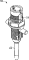
With reference to figure 1-7, small-sized according to an embodiment of the invention bar positor apparatus 100 comprises external drive sleeve 110, keeps guide ring 120 and corrugated tubing 130.Bar positor 100 can be optionally engage with rods 140 and awl nut screw assembly 150, and described awl nut screw assembly can adopt following form: single shaft awl nut nail, sagittal screw, multiaxis are bored nut nail, hook or are comprised the head of the far-end that is configured to engage threads pipe 130 or the screw of nearly all type of anchoring part.In one example, external drive sleeve 110 comprise near-end, far-end, in the longitudinal axis between near-end and the far-end, hollow tubular inside, be arranged on grip surface 112 on the near-end outer surface (described near-end outer surface can comprise cutting or other tractive grip surface), can realize observing and its visibility window 114 that weight resets, such as drive surfaces 116 and a series of female thread 118 that is arranged on the far-end inner surface of the hex driver that is arranged on near-end inside.In one example, drive surfaces 116 can engage with the ratchet T type handle drives apparatus (Fig. 7) that has hex drive coupling 160, so that apply extra mechanical revolving force to outside drive sleeve 110, thereby auxiliary rod resets.
In one example, corrugated tubing 130 comprises near-end, far-end, the longitudinal axis between near-end and far-end, hollow tubular inside, first shank 132 and second shank 134.In one example, first shank 132 and second shank 134 keep together by the internal constraint of external drive sleeve 110 and maintenance guide ring 120.In some examples, first shank 132 comprises external screw thread 136A, and second shank 134 comprises external screw thread 136B. External screw thread 136A and 136B can be that single thread or multi start thread are to provide reset speed faster.In one example, external screw thread 136A and 136B are two-start screw M18 * 1.5 with 3mm effective pitch.In some instances, first shank 132 comprises the joint elements 138A of its far-end inside, and second shank 134 comprises the joint elements 138B of its far-end inside. Joint elements 138A, 138B optionally engage and are connected to the outer surface of awl nut screw assembly 150.In one example, joint elements 138A, 138B include sun projection, its with the outer surface of awl nut screw assembly 150 on inherent cloudy slot be complementary.In one example, joint elements 138A, 138B and corresponding slot thereof all provide stability on all three axis, as Fig. 6 A is illustrated best.In one example, first shank 132 comprises the parts 139A that externally is provided with near near-end, and second shank 134 comprises the parts 139B that externally is provided with near near-end.In one example, the pitch diameter of thread that parts 139A, the 139B of outer setting includes the external diameter of corrugated tubing 130 wherein and external screw thread 136A, 136B reduces allowing the first arm 132 and second arm 134 in the open a little zone of far-end, thereby makes bar positor 100 can easily introduce and make the corresponding joint of slot of joint elements 138A, 138B and awl nut screw assembly 150 on whole awl nut screw assembly 150.In one example, the first arm 132 and second arm 134 are configured to open about 2.5 degree at far-end.
In one example, maintenance guide ring 120 externally drive sleeve 110 far-ends is provided with around corrugated tubing 130, and the bar recess 126 that comprises the upwardly extending the first arm 122A and the second arm 122B, is separately positioned on the outward extending first lug 124A and the second lug 124B on the end of upwardly extending arm 122A and 122B and is arranged on the far-end that keeps guide ring 120, described bar recess optionally is connected with rods 140.
In one example, external drive sleeve 110 is made of rustless steel, titanium or other biocompatible surgical grade metal, and keeps guide ring 120 and corrugated tubing 130 to be made of biocompatible polymeric material such as polyether-ether-ketone (PEEK).But, drive sleeve 110 is not limited to metal construction, and keep guide ring 120 and corrugated tubing 130 also to be not limited to polymer architecture, and in them each can be made of any biocompatible material that can have the approximate shape of described parts and can stand the normal operating condition of described parts.For example, keep guide ring 120 and corrugated tubing 130 to constitute, and drive sleeve 110 can be made of PEEK by titanium.
In operation, continue with reference to figure 1-7, in awl nut nail or the several awl nut screw assembly 150 implanted patient's vertebrae, and bar 140 can be to be possible malformation correction prebuckling herein.Under the situation that does not need to reset, rods 140 loosely is placed on the structure of boring nut nail 150 and is attached to awl nut nail 150.The grip surface 112 of external drive sleeve 110 is utilized manually rotation engage threads pipe 130 and with respect to rotated threaded tubular, and/or external drive sleeve 110 can utilize and has the ratchet T type handle drives apparatus that hexagon drives coupling 160 and rotate via drive surfaces 116.Keep guide ring 120 far-end of the win shank 132 and second shank 134 to be opened around parts 139A and 139B.The far-end of bar positor 100 is placed on the rods 140 and is positioned on the awl nut screw assembly 150, makes win shank 132 and second shank 134 straddle bar 140, and joint elements 138A and the 138B corresponding slot on the awl nut screw assembly 150.External drive sleeve 110 passes through grip surface 112 subsequently with respect to corrugated tubing 130 hand rotation, and/or rotation has the ratchet T type handle drives apparatus that hexagon drives coupling 160, so that keep guide ring 120 and external drive sleeve 110 by the female thread 118 and the first and second external screw thread 136A, the joint of 136B is advanced to far-end with respect to corrugated tubing 130, thereby causes not the opening of far-end of the first arm 132 and second arm 134, the first and second joint elements 138A, 138B engages with the slot that the awl nut is followed closely on 150, bar recess 126 joins on the rods 140, and rods 140 is shifted downwards with respect to first shank 132 and second shank 134.A plurality of bar positor apparatuses 100 can use in this way so that gradually rods 140 is reset in a plurality of awl nut screw assemblies 150 on a plurality of vertebra joints.In one example, bar positor 100 activates lentamente, symmetrically to avoid making awl nut screw assembly 150 and the basivertebral interface corresponding with it bear excessive pressure, and this further allows to make the progressively pressure-bearing and the stretching of soft tissue of patient's spinal column in the possibility correction deformity.The ratchet T type handle drives device apparatus that has hexagon driving coupling 160 is thrown off from external drive sleeve 110 and locking cap subsequently, introduce rods 140 finally with respect to awl nut screw assembly 150 fixed elements by bar positor 100 via the locking cap passage, described locking cap passage is provided by the inner geometry structure of corrugated tubing 130.Locking cap can utilize medicated cap drive assembly (not shown) to be connected to awl nut screw assembly 150, and described medicated cap drive assembly can insert by bar positor 100.Locking cap driver 160 has joint elements, is used to be connected to locking cap and activates their connections to awl nut screw assembly 150, and for example screw thread, star driver or hexagon drive joint elements.Locking cap driver 160 can be the ratchet driver, but is not so limited.In one example, locking cap is connected to awl nut screw assembly 150, and locking cap driver 160 is thrown off from bar positor 100.Bar positor 100 is last and throw off with awl nut screw assembly 150 and to connect by keeping guide ring 120 to be placed on parts 139A, 139B, make the far-end of arm 132,134 open, and joint elements 138A, 138B are disengaged with their corresponding slots on the awl nut screw assembly 150.Bar positor 100 can be cleaned and sterilize for reusing.
In some instances, bar positor 100 need not slot or destroy the outside of rods 140 at its reseting period.In addition, the bar positor 100 of some examples prevents opening of upwardly extending arm so that form the bar receive path of awl nut screw assembly 150.
In one example, with reference to figure 8A-8D, be provided with bar positor 200, it is configured to be connected to the rods 140 that single shaft is bored nut nail 250 and resetted and be attached thereto especially.In one example, bar positor 200 comprises that far-end ends at the thread spindle 210 of holding element 220, is used to be connected to the downside that single shaft is bored the far-end of nut screw assembly 250.Bar positor 200 also comprises nut 230, and described nut configuration is for being connected with the external screw thread of axle 210 and threadably being shifted with respect to the external screw thread of axle.In one example, the pawl element 240 with one or more arm is connected to the axle 210 under the nut 230, and in another example, one or more arm has bar recess 242, is used for engagement ridge mast 140.
In operation, continue, hold element 220 and be placed on single shaft and bore nut and follow closely 250 belows with reference to figure 8A-8D.The proximal lateral of pawl element 240 engagement ridge masts, and nut 230 rotates to force pawl element 240 via bar recess 242 bar 140 to be reset in the single shaft awl nut screw assembly 250.Locking cap is connected to single shaft awl nut screw assembly 250, and by unclamping nut 230 and pawl 240 and rods 140 being disengaged bar positor 200 is connected with 250 disengagements of single shaft awl nut screw assembly.
In one example, with reference to figure 9A-9F, bar positor 300 is set, it comprises six-sided nut 310, has the corrugated tubing 330 of first shank 332 and second shank 334 and keeps guide ring 320.In one example, bar positor 300 is similar with bar positor 100 in function and operation, just bar positor 300 includes six-sided nut 310 and is used for combining actuator lever positor 300 with the poroid device (not shown) of hexagon, to replace external drive sleeve 110.Corrugated tubing 330 is similar with corrugated tubing 130 in function and operation, but corrugated tubing 330 is combined with hinge design in the proximal end, in order to control opening of first shank 332 and second shank 334.
Those skilled in the art will recognize that the foregoing description to change and do not break away from broad sense inventive concept of the present invention.Therefore be to be understood that to the invention is not restricted to described specific embodiment, it just attempts to comprise the various modification in the spirit and scope of the invention, as this description limited.
The above-mentioned specific embodiment comprises the incorporated by reference to accompanying drawing, and accompanying drawing forms the part of the specific embodiment.Accompanying drawing has shown specific implementations by illustrated mode, and the present invention can be with this embodiment practice.These embodiments are also referred to as " example " at this.All publications of quoting in presents, patent and patent document integral body by reference are contained in this, as in being included in by reference separately.When inconsistent usage appearred in presents and those files of comprising by reference, the usage in the list of references that is comprised should be considered to the replenishing of usage in the presents; Inconsistent situation for contradiction is as the criterion with the usage in the presents.
In presents, except any other example or the usage of " at least one " or " one or more ", as in patent document like that, employed term " " or " a kind of " comprise one or more than one.In presents, unless otherwise indicated, otherwise term " or " be used to refer to non-exclusionism or relation, thereby " A or B " comprises " A but be not B ", " B but be not A " and " A and B ".In the appended claims, term " comprise " and " therein " to be taken as be " to include " with corresponding term and statement that " wherein " is of equal value.In addition, in following claim, term " comprises " and " including " is open, in the claims, comprises that system, device, article or the method for the element those elements after being listed in above-mentioned term still is considered to fall within the scope of this claim that is:.And in following claim, term " first ", " second " and " the 3rd " etc. only are used to work as and make a check mark, rather than intention applies digital requirement on their object.
Above-mentioned explanation is intended to explain rather than restriction.For example, above-mentioned example (perhaps its one or more feature) can combination with one another be used.Other embodiment also can for example be used on the basis of reading above-mentioned description by those skilled in the art.In addition, in the above-mentioned specific embodiment, various features can be integrated into together so that the disclosure is simplified.This should not be interpreted as following attempt, that is: the open feature that excludes claim all is necessary for each bar claim.On the contrary, subject matter can be less than all features of disclosed specific embodiment and exist.Therefore, following claim is incorporated within the specific embodiment in view of the above, and each bar claim is represented self becomes an independently embodiment.Should determine the four corner of the equivalent that scope of the present invention and these claim are authorized with reference to claims.
Specification digest allows the reader to confirm the disclosed essence of present technique fast.Should follow such common recognition, promptly specification digest will not be used to explain or limit the scope or the meaning of claim.
Claims (36)
1. one kind is configured to the device that optionally engages with rods and implantable screw assembly, and described device comprises:
First screw element comprises that described first screw element comprises the joint elements that are configured to optionally described first screw element be anchored to described implantable screw assembly around first screw thread of at least a portion of the outer surface of described first screw element;
Second screw element, comprise second screw thread around at least a portion of the inner surface of described second screw element, described second screw element is configured to threadably engage with described first screw element, and described second screw element can move with respect to described first screw element vertically along with the rotation of described second screw element; And
The rods impeller, this rods impeller can move vertically with described second screw element, described impeller comprises area supported, described area supported is configured to the optionally described rods of butt, and along with described second screw element along the rotation of first rotation direction and optionally promote described rods towards described implantable screw assembly.
2. device according to claim 1, wherein said joint elements comprise at least one projection, described at least one projection is configured to be complementary with the slot of the corresponding number of described implantable screw assembly.
3. device according to claim 1, wherein said joint elements comprise holds element, describedly holds the near-end that element is configured to optionally be connected to described implantable screw assembly.
4. device according to claim 1, wherein said joint elements are arranged on the far-end of described first screw element.
5. device according to claim 1, wherein said impeller are connected to described second screw element.
6. device according to claim 1, wherein said first screw element is piped substantially, and comprise first shank and second shank, described first shank and second shank extend basically vertically, and the far-end of the far-end of wherein said first shank and second shank is configured to and can optionally radially separates.
7. device according to claim 6, the cross section of wherein said first shank and second shank are semicircle basically.
8. device according to claim 7, described first shank and second shank of wherein said first screw element keep together by described second screw element, described second screw element threadably be bonded on described first screw element outer surface around.
9. device according to claim 8, the outer surface of wherein said first screw element comprises the part that diameter reduces, and the section construction that described diameter reduces is optionally radially separated with described first screw element that threadably engages described second screw element with second shank for allowing described first shank.
10. device according to claim 6, wherein said first screw element comprise described gap between first shank and described second shank, and described gap is configured to hold described rods.
11. device according to claim 10, the described area supported of wherein said impeller are at least partially disposed in the described gap between described first shank and described second shank.
12. device according to claim 1, wherein said second screw element comprises the tool engagement part, and described tool engagement section construction is and tool engagement that described tool configuration is rotated with respect to described first screw element for making described second screw element.
13. device according to claim 12, wherein said tool engagement partly comprises recess, and described recess comprises drive surfaces, and described drive surfaces is configured to be complementary with described instrument.
14. partly comprising, device according to claim 12, wherein said tool engagement be configured to the nut that is complementary with described instrument.
15. device according to claim 14, wherein said nut comprises six-sided nut.
16. device according to claim 1, wherein said rods impeller comprises the pawl element, and described pawl element comprises one or more arm, and each arm comprises and is configured to the optionally described area supported of the described rods of butt.
17. device according to claim 16, the area supported of wherein said each arm are arranged on the place, end of described arm.
18. device according to claim 16, wherein said area supported comprises the bar recess.
19. device according to claim 1, the described joint elements of wherein said first screw element comprise holds element, describedly holds the downside that element is configured to be connected to the head of described implantable screw assembly.
20. device according to claim 1, wherein said second screw element comprises grip surface, and described grip surface is configured to grasp during with respect to described second screw element of the described first screw element hand rotation.
21. a method comprises:
Place at least one bar positor and described at least one bar positor is alignd with at least one awl nut nail basically along rods, wherein saidly place at least one bar positor along rods and comprise that basically the area supported with the rods impeller of described bar positor aligns with described rods;
Described bar positor and the nail joint of described awl nut are closed;
Described bar positor is activated with incremental mode, close so that little by little described rods is reset to the nail joint of described awl nut, the actuating of wherein said bar positor causes described area supported to move towards described awl nut nail, thereby promotes described rods towards described awl nut nail; And
Described awl nut nail is engaged with described rods.
22. method according to claim 21 wherein makes described awl nut nail and engaging of described rods comprise locking cap is attached to described awl nut nail, to keep described rods and engaging that described awl nut is followed closely.
23. method according to claim 21 is removed described bar positor from described awl nut nail after being included in described awl nut nail and described rods engaging.
24. method according to claim 23 is included in described bar positor after the removal of described awl nut nail, cleans described bar positor in order to reusing.
25. method according to claim 21 is wherein saidly placed at least one bar positor along rods and is comprised along described rods and place two or more bar positors and described two or more bar positors are alignd with two or more awl nuts nails basically.
26. method according to claim 21 comprises:
Place described rods along a plurality of awl nut nails;
For the situation that does not need rods to reset, do not use the bar positor and join described rods to one or more awl nut nail; And
For the situation that needs rods to reset, use one or more bar positor to join described rods to one or more awl nut nail.
27. method according to claim 21, wherein said bar positor comprise manually with engaging of described awl nut nail described bar positor and the nail joint of described awl nut are closed.
Utilize instrument that described bar positor and the nail joint of described awl nut are closed 28. method according to claim 21, wherein said bar positor comprise with engaging of described awl nut nail, described tool configuration partly is complementary for the tool engagement with described bar positor.
29. a rods resetting system comprises:
Rods;
A plurality of awl nut nails are configured to engage with described rods; And
A plurality of bar positors, each bar positor includes:
First screw element comprises that described first screw element comprises joint elements around first screw thread of at least a portion of the outer surface of described first screw element, and described joint elements are configured to optionally described first screw element be anchored to described awl nut nail;
Second screw element, comprise second screw thread around at least a portion of the inner surface of described second screw element, described second screw element is configured to threadably engage with described first screw element, and described second screw element can move with respect to described first screw element vertically along with the rotation of described second screw element; And
The rods impeller, this rods impeller can move vertically with described second screw element, described impeller comprises area supported, described area supported is configured to the optionally described rods of butt, and along with described second screw element optionally promotes described rods towards described awl nut nail along the rotation of first rotation direction.
30. rods resetting system according to claim 29, wherein said bar positor are configured to engage with described awl nut nail and described rods with described awl nut nail spaced positions place in described rods.
31. rods resetting system according to claim 29, wherein said a plurality of bar positors are configured to promote described rods with incremental mode towards described a plurality of awl nut nails.
32. rods resetting system according to claim 29 comprises locking cap, described locking cap is configured to merge with described awl nut nail joint and keep described rods and engaging that described awl nut is followed closely.
33. rods resetting system according to claim 29 comprises instrument, described tool configuration partly is complementary for the tool engagement with each described bar positor, and described tool configuration is rotated with respect to described first screw element for making described second screw element.
34. rods resetting system according to claim 33, wherein said tool engagement partly comprises recess, and described recess comprises and is configured to the drive surfaces that is complementary with described instrument.
35. partly comprising, rods resetting system according to claim 33, wherein said tool engagement be configured to the nut that is complementary with described instrument.
36. a rods reset assembly comprises:
One or more awl nut nail that engages with one or more vertebra;
Basically follow closely the rods of aliging with described one or more awl nut; And
At least one bar positor, described at least one bar positor removably engages in the position that described rods and described awl nut are followed closely spaced apart certain distance with at least one awl nut nail, described bar positor comprises the rods impeller, described rods impeller can move vertically with respect to described bar positor, described impeller comprises area supported, described area supported is configured to the optionally described rods of butt, and optionally utilize the actuating of described bar positor and promote described rods, to reduce the distance between described rods and the described awl nut nail towards described awl nut nail.
Applications Claiming Priority (3)
| Application Number | Priority Date | Filing Date | Title |
|---|---|---|---|
| US13839208P | 2008-12-17 | 2008-12-17 | |
| US61/138,392 | 2008-12-17 | ||
| PCT/US2009/006433 WO2010077284A1 (en) | 2008-12-17 | 2009-12-08 | Rod reducer apparatus for spinal corrective surgery |
Publications (1)
| Publication Number | Publication Date |
|---|---|
| CN102256558A true CN102256558A (en) | 2011-11-23 |
Family
ID=41786245
Family Applications (1)
| Application Number | Title | Priority Date | Filing Date |
|---|---|---|---|
| CN2009801507487A Pending CN102256558A (en) | 2008-12-17 | 2009-12-08 | Rod reducer apparatus for spinal corrective surgery |
Country Status (8)
| Country | Link |
|---|---|
| US (3) | US9161788B2 (en) |
| EP (1) | EP2373238B1 (en) |
| JP (1) | JP2012511997A (en) |
| KR (1) | KR20110112306A (en) |
| CN (1) | CN102256558A (en) |
| BR (1) | BRPI0922953A2 (en) |
| CA (1) | CA2746013A1 (en) |
| WO (1) | WO2010077284A1 (en) |
Cited By (1)
| Publication number | Priority date | Publication date | Assignee | Title |
|---|---|---|---|---|
| CN110251221A (en) * | 2018-03-12 | 2019-09-20 | 捷迈拜欧米特脊柱有限公司 | Bar restorer ratchet lock mechanism |
Families Citing this family (38)
| Publication number | Priority date | Publication date | Assignee | Title |
|---|---|---|---|---|
| US8439922B1 (en) | 2008-02-06 | 2013-05-14 | NiVasive, Inc. | Systems and methods for holding and implanting bone anchors |
| JP2012511997A (en) | 2008-12-17 | 2012-05-31 | ジンテス ゲゼルシャフト ミット ベシュレンクテル ハフツング | Rod reducer device for spinal correction surgery |
| US8795283B2 (en) * | 2009-12-28 | 2014-08-05 | Safe Orthopaedics Sas | Instrument kit for performing spinal stabilization |
| WO2011106339A1 (en) | 2010-02-23 | 2011-09-01 | K2M, Inc. | Polyaxial bone screw assembly |
| US8202274B2 (en) * | 2010-06-18 | 2012-06-19 | Spine Wave, Inc. | Apparatus and method for detecting a connecting rod during percutaneous surgery |
| US8882817B2 (en) | 2010-08-20 | 2014-11-11 | K2M, Inc. | Spinal fixation system |
| US9393049B2 (en) | 2010-08-20 | 2016-07-19 | K2M, Inc. | Spinal fixation system |
| AU2013201293B2 (en) * | 2010-08-20 | 2014-12-18 | K2M, Inc. | Spinal Fixation System |
| US9198698B1 (en) | 2011-02-10 | 2015-12-01 | Nuvasive, Inc. | Minimally invasive spinal fixation system and related methods |
| FR2976784B1 (en) * | 2011-06-23 | 2013-07-05 | Spineway | SURGICAL DEVICE FOR THE CORRECTION OF DEFORMATION OF THE VERTEBRAL COLUMN |
| US9125703B2 (en) * | 2012-01-16 | 2015-09-08 | K2M, Inc. | Rod reducer, compressor, distractor system |
| FR2988993B1 (en) * | 2012-04-05 | 2014-03-21 | Safe Orthopaedics | INSTRUMENT AND SURGICAL SYSTEM FOR FIXING VERTEBRATES |
| ES2696676T3 (en) * | 2012-09-04 | 2019-01-17 | Trigueros Ignacio Sanpera | System for a three-dimensional global correction of the curvatures of the column |
| US9918752B2 (en) * | 2012-11-29 | 2018-03-20 | Warsaw Orthopedic, Inc. | Spinal implant system and method |
| US10136927B1 (en) | 2013-03-15 | 2018-11-27 | Nuvasive, Inc. | Rod reduction assemblies and related methods |
| US9486256B1 (en) | 2013-03-15 | 2016-11-08 | Nuvasive, Inc. | Rod reduction assemblies and related methods |
| US20150100098A1 (en) * | 2013-10-07 | 2015-04-09 | K2M, Inc. | Rod reducer |
| US20160287293A1 (en) * | 2013-11-22 | 2016-10-06 | Spinal Balance, Inc. | Poly-Axial Pedicle Screw Assembly and Packaging Therefor |
| US9271768B2 (en) * | 2013-12-20 | 2016-03-01 | Globus Medical, Inc. | Orthopedic fixation devices and instruments for installation thereof |
| EP2939622A1 (en) | 2014-04-30 | 2015-11-04 | Sanpera Trigueros, Ignacio | System for correction of the spine curvatures |
| US20160106480A1 (en) * | 2014-07-02 | 2016-04-21 | Yue Zhou | Extension piece at screw end of pedicle screw, dilator and push rod reset lever |
| US20160058482A1 (en) * | 2014-08-07 | 2016-03-03 | Jeffrey Scott Smith | Rod delivery tool for use in pedicle screw systems |
| DE102014114530A1 (en) * | 2014-10-07 | 2016-04-07 | Aesculap Ag | Locking sleeve for a pedicle screw |
| EP3092965B1 (en) * | 2015-05-15 | 2020-11-18 | Biedermann Technologies GmbH & Co. KG | Instrument for use with a bone anchoring device in spinal surgery and system including the instrument and a bone anchoring device |
| US9974577B1 (en) | 2015-05-21 | 2018-05-22 | Nuvasive, Inc. | Methods and instruments for performing leveraged reduction during single position spine surgery |
| US10123829B1 (en) | 2015-06-15 | 2018-11-13 | Nuvasive, Inc. | Reduction instruments and methods |
| DE102016106608A1 (en) * | 2016-04-11 | 2017-10-12 | Aesculap Ag | Instrument for guiding a rod into an implant receptacle |
| US10524843B2 (en) | 2016-05-06 | 2020-01-07 | K2M, Inc. | Rotation shaft for a rod reducer |
| JP2019525797A (en) * | 2016-07-04 | 2019-09-12 | スピナル バランス,インク. | Combined protective container and delivery device for pedicle screw |
| US10398481B2 (en) | 2016-10-03 | 2019-09-03 | Nuvasive, Inc. | Spinal fixation system |
| US20190282320A1 (en) * | 2016-10-12 | 2019-09-19 | Medical AccuFix, LLC | Methods and devices for medical device placement |
| US10779866B2 (en) | 2016-12-29 | 2020-09-22 | K2M, Inc. | Rod reducer assembly |
| US10485590B2 (en) | 2017-01-18 | 2019-11-26 | K2M, Inc. | Rod reducing device |
| US10646260B2 (en) | 2017-05-03 | 2020-05-12 | Advance Research System, Llc | Extension ready spinal support systems |
| US11648037B2 (en) | 2017-05-03 | 2023-05-16 | Advance Research System, Llc | Extension-ready spinal support system with vascular-safe pedicle screw |
| US11051861B2 (en) | 2018-06-13 | 2021-07-06 | Nuvasive, Inc. | Rod reduction assemblies and related methods |
| CN114025695A (en) * | 2019-03-12 | 2022-02-08 | 碳固定脊柱股份有限公司 | Spinal implant of composite material |
| US11553947B2 (en) | 2019-07-16 | 2023-01-17 | Aesculap Implant Systems, Llc | Spinal deformity sequential persuader |
Citations (2)
| Publication number | Priority date | Publication date | Assignee | Title |
|---|---|---|---|---|
| US20060095035A1 (en) * | 2004-11-03 | 2006-05-04 | Jones Robert J | Instruments and methods for reduction of vertebral bodies |
| US20080119852A1 (en) * | 2006-11-20 | 2008-05-22 | Dalton Brian E | Bone repair device and method |
Family Cites Families (74)
| Publication number | Priority date | Publication date | Assignee | Title |
|---|---|---|---|---|
| US4411259A (en) | 1980-02-04 | 1983-10-25 | Drummond Denis S | Apparatus for engaging a hook assembly to a spinal column |
| US5020519A (en) | 1990-12-07 | 1991-06-04 | Zimmer, Inc. | Sagittal approximator |
| GB9110778D0 (en) | 1991-05-18 | 1991-07-10 | Middleton Jeffrey K | Apparatus for use in surgery |
| DE4238339C2 (en) | 1992-11-13 | 1994-10-06 | Peter Brehm | Pedicle screw and holding hook for fixing a stiffening rod and instruments for adjusting and attaching the stiffening rod to the pedicle screw or holding hook |
| US5364397A (en) | 1993-06-01 | 1994-11-15 | Zimmer, Inc. | Spinal coupler seater with dual jaws and an independent plunger |
| US5584831A (en) * | 1993-07-09 | 1996-12-17 | September 28, Inc. | Spinal fixation device and method |
| US5616143A (en) | 1995-02-06 | 1997-04-01 | Schlapfer; Johannes F. | Surgical forceps |
| US5782830A (en) | 1995-10-16 | 1998-07-21 | Sdgi Holdings, Inc. | Implant insertion device |
| US6063088A (en) | 1997-03-24 | 2000-05-16 | United States Surgical Corporation | Method and instrumentation for implant insertion |
| US5720751A (en) | 1996-11-27 | 1998-02-24 | Jackson; Roger P. | Tools for use in seating spinal rods in open ended implants |
| US5810878A (en) | 1997-02-12 | 1998-09-22 | Sdgi Holdings, Inc. | Rod introducer forceps |
| US5910141A (en) * | 1997-02-12 | 1999-06-08 | Sdgi Holdings, Inc. | Rod introduction apparatus |
| US6042582A (en) | 1997-05-20 | 2000-03-28 | Ray; Charles D. | Instrumentation and method for facilitating insertion of spinal implant |
| US5944720A (en) | 1998-03-25 | 1999-08-31 | Lipton; Glenn E | Posterior spinal fixation system |
| WO2002058600A2 (en) * | 2001-01-26 | 2002-08-01 | Osteotech, Inc. | Implant insertion tool |
| US7862587B2 (en) * | 2004-02-27 | 2011-01-04 | Jackson Roger P | Dynamic stabilization assemblies, tool set and method |
| US6440133B1 (en) | 2001-07-03 | 2002-08-27 | Sdgi Holdings, Inc. | Rod reducer instruments and methods |
| US7250052B2 (en) * | 2002-10-30 | 2007-07-31 | Abbott Spine Inc. | Spinal stabilization systems and methods |
| US7988698B2 (en) | 2003-01-28 | 2011-08-02 | Depuy Spine, Inc. | Spinal rod approximator |
| US7621918B2 (en) * | 2004-11-23 | 2009-11-24 | Jackson Roger P | Spinal fixation tool set and method |
| US7156849B2 (en) | 2003-06-16 | 2007-01-02 | Depuy Spine, Inc. | Rod reduction nut and driver tool |
| US8398682B2 (en) * | 2003-06-18 | 2013-03-19 | Roger P. Jackson | Polyaxial bone screw assembly |
| US20040267275A1 (en) | 2003-06-26 | 2004-12-30 | Cournoyer John R. | Spinal implant holder and rod reduction systems and methods |
| US7179261B2 (en) | 2003-12-16 | 2007-02-20 | Depuy Spine, Inc. | Percutaneous access devices and bone anchor assemblies |
| US7666188B2 (en) * | 2003-12-16 | 2010-02-23 | Depuy Spine, Inc. | Methods and devices for spinal fixation element placement |
| US8066739B2 (en) * | 2004-02-27 | 2011-11-29 | Jackson Roger P | Tool system for dynamic spinal implants |
| US7470279B2 (en) * | 2004-02-27 | 2008-12-30 | Jackson Roger P | Orthopedic implant rod reduction tool set and method |
| US8152810B2 (en) * | 2004-11-23 | 2012-04-10 | Jackson Roger P | Spinal fixation tool set and method |
| US7611517B2 (en) | 2004-02-27 | 2009-11-03 | Warsaw Orthopedic, Inc. | Rod reducer |
| EP1720468A4 (en) * | 2004-02-27 | 2010-01-27 | Roger P Jackson | Orthopedic implant rod reduction tool set and method |
| JP4213609B2 (en) * | 2004-03-09 | 2009-01-21 | 昭和医科工業株式会社 | Rod fixing aid |
| CN101090674A (en) | 2004-07-06 | 2007-12-19 | 芯赛斯公司 | Spinal rod insertion instrument |
| US7572281B2 (en) | 2004-08-06 | 2009-08-11 | Depuy Spine, Inc. | Instrument for guiding a rod into an implant in a spinal fixation system |
| US7651502B2 (en) * | 2004-09-24 | 2010-01-26 | Jackson Roger P | Spinal fixation tool set and method for rod reduction and fastener insertion |
| US7666189B2 (en) * | 2004-09-29 | 2010-02-23 | Synthes Usa, Llc | Less invasive surgical system and methods |
| EP1811911A4 (en) * | 2004-11-10 | 2012-01-11 | Roger P Jackson | Helical guide and advancement flange with break-off extensions |
| WO2006091863A2 (en) * | 2005-02-23 | 2006-08-31 | Pioneer Laboratories, Inc. | Minimally invasive surgical system |
| CA2614898C (en) | 2005-04-27 | 2014-04-22 | Trinity Orthopedics, Llc | Mono-planar pedilcle screw method, system, and kit |
| US7758617B2 (en) * | 2005-04-27 | 2010-07-20 | Globus Medical, Inc. | Percutaneous vertebral stabilization system |
| US7491208B2 (en) | 2005-04-28 | 2009-02-17 | Warsaw Orthopedic, Inc. | Instrument and method for guiding surgical implants and instruments during surgery |
| US7608081B2 (en) | 2005-05-23 | 2009-10-27 | Custom Spine, Inc. | Rod reducer |
| US7771430B2 (en) | 2005-09-29 | 2010-08-10 | K2M, Inc. | Single action anti-torque rod reducer |
| US7931654B2 (en) * | 2006-03-09 | 2011-04-26 | K2M, Inc. | Dual action rod reducing and locking device and method |
| US7927334B2 (en) | 2006-04-11 | 2011-04-19 | Warsaw Orthopedic, Inc. | Multi-directional rod reducer instrument and method |
| US8216240B2 (en) | 2006-04-24 | 2012-07-10 | Warsaw Orthopedic | Cam based reduction instrument |
| US8192438B2 (en) | 2006-05-18 | 2012-06-05 | Phygen, LLC. | Rod reducer |
| US8551141B2 (en) * | 2006-08-23 | 2013-10-08 | Pioneer Surgical Technology, Inc. | Minimally invasive surgical system |
| US7686809B2 (en) | 2006-09-25 | 2010-03-30 | Stryker Spine | Rod inserter and rod with reduced diameter end |
| US8096996B2 (en) | 2007-03-20 | 2012-01-17 | Exactech, Inc. | Rod reducer |
| US8679128B2 (en) * | 2006-12-07 | 2014-03-25 | Zimmer Spine, Inc. | Apparatus and methods for reduction of vertebral bodies in a spine |
| US20080234765A1 (en) | 2007-03-13 | 2008-09-25 | Depuy Spine, Inc. | Rod reduction methods and devices |
| US8172847B2 (en) | 2007-03-29 | 2012-05-08 | Depuy Spine, Inc. | In-line rod reduction device and methods |
| US7947046B2 (en) * | 2007-06-21 | 2011-05-24 | Warsaw Orthopedic, Inc. | Anchor extenders for minimally invasive surgical procedures |
| US8048129B2 (en) * | 2007-08-15 | 2011-11-01 | Zimmer Spine, Inc. | MIS crosslink apparatus and methods for spinal implant |
| US8414588B2 (en) * | 2007-10-04 | 2013-04-09 | Depuy Spine, Inc. | Methods and devices for minimally invasive spinal connection element delivery |
| US8540718B2 (en) * | 2007-10-23 | 2013-09-24 | Aesculap Implant Systems, Llc | Rod persuader |
| US8366714B2 (en) * | 2007-10-23 | 2013-02-05 | K2M, Inc. | Rod insertion instrument and method of use |
| US8439922B1 (en) * | 2008-02-06 | 2013-05-14 | NiVasive, Inc. | Systems and methods for holding and implanting bone anchors |
| US8608746B2 (en) * | 2008-03-10 | 2013-12-17 | DePuy Synthes Products, LLC | Derotation instrument with reduction functionality |
| US8915944B2 (en) * | 2008-04-15 | 2014-12-23 | Perumala Corporation | Rod and plate system for incremental reduction of the spine |
| US9504494B2 (en) * | 2008-04-28 | 2016-11-29 | DePuy Synthes Products, Inc. | Implants for securing spinal fixation elements |
| WO2009158707A1 (en) * | 2008-06-27 | 2009-12-30 | K2M, Inc. | System and method for performing spinal surgery |
| US20100168796A1 (en) * | 2008-07-29 | 2010-07-01 | Kenneth Arden Eliasen | Bone anchoring member with clamp mechanism |
| JP2012511997A (en) | 2008-12-17 | 2012-05-31 | ジンテス ゲゼルシャフト ミット ベシュレンクテル ハフツング | Rod reducer device for spinal correction surgery |
| US8206394B2 (en) * | 2009-05-13 | 2012-06-26 | Depuy Spine, Inc. | Torque limited instrument for manipulating a spinal rod relative to a bone anchor |
| DE112010004338B4 (en) * | 2009-11-10 | 2019-06-27 | Nuvasive, Inc. | DEVICE FOR IMPLEMENTING SPINE SURGERY |
| US8545505B2 (en) * | 2010-01-15 | 2013-10-01 | Pioneer Surgical Technology, Inc. | Low friction rod persuader |
| US8523873B2 (en) * | 2010-04-08 | 2013-09-03 | Warsaw Orthopedic, Inc. | Neural-monitoring enabled sleeves for surgical instruments |
| US8202274B2 (en) * | 2010-06-18 | 2012-06-19 | Spine Wave, Inc. | Apparatus and method for detecting a connecting rod during percutaneous surgery |
| US8394108B2 (en) * | 2010-06-18 | 2013-03-12 | Spine Wave, Inc. | Screw driver for a multiaxial bone screw |
| US9186184B2 (en) * | 2011-02-14 | 2015-11-17 | Pioneer Surgical Technology, Inc. | Spinal fixation system and method |
| US8764756B2 (en) * | 2011-02-22 | 2014-07-01 | K2M, Inc. | Single action anti-torque rod reducer |
| US8439924B1 (en) * | 2012-04-02 | 2013-05-14 | Warsaw Orthopedic, Inc. | Spinal implant system and method |
| US20140343613A1 (en) * | 2013-05-17 | 2014-11-20 | Kenneth Arden Eliasen | Bone anchoring member with clamp mechanism |
-
2009
- 2009-12-08 JP JP2011542114A patent/JP2012511997A/en not_active Abandoned
- 2009-12-08 WO PCT/US2009/006433 patent/WO2010077284A1/en active Application Filing
- 2009-12-08 US US13/139,373 patent/US9161788B2/en active Active
- 2009-12-08 EP EP09775382.6A patent/EP2373238B1/en active Active
- 2009-12-08 CA CA2746013A patent/CA2746013A1/en not_active Abandoned
- 2009-12-08 CN CN2009801507487A patent/CN102256558A/en active Pending
- 2009-12-08 BR BRPI0922953A patent/BRPI0922953A2/en not_active IP Right Cessation
- 2009-12-08 KR KR1020117014613A patent/KR20110112306A/en not_active Application Discontinuation
-
2015
- 2015-09-15 US US14/854,424 patent/US9636152B2/en active Active
-
2017
- 2017-04-05 US US15/479,789 patent/US9962198B2/en active Active
Patent Citations (2)
| Publication number | Priority date | Publication date | Assignee | Title |
|---|---|---|---|---|
| US20060095035A1 (en) * | 2004-11-03 | 2006-05-04 | Jones Robert J | Instruments and methods for reduction of vertebral bodies |
| US20080119852A1 (en) * | 2006-11-20 | 2008-05-22 | Dalton Brian E | Bone repair device and method |
Cited By (2)
| Publication number | Priority date | Publication date | Assignee | Title |
|---|---|---|---|---|
| CN110251221A (en) * | 2018-03-12 | 2019-09-20 | 捷迈拜欧米特脊柱有限公司 | Bar restorer ratchet lock mechanism |
| US11730523B2 (en) | 2018-03-12 | 2023-08-22 | Zimmer Biomet Spine, Inc. | Rod reducer ratchet lock-out mechanism |
Also Published As
| Publication number | Publication date |
|---|---|
| EP2373238B1 (en) | 2013-09-25 |
| US20160000479A1 (en) | 2016-01-07 |
| WO2010077284A1 (en) | 2010-07-08 |
| BRPI0922953A2 (en) | 2016-01-19 |
| US20170202583A1 (en) | 2017-07-20 |
| US9636152B2 (en) | 2017-05-02 |
| US9962198B2 (en) | 2018-05-08 |
| US20120271365A1 (en) | 2012-10-25 |
| KR20110112306A (en) | 2011-10-12 |
| JP2012511997A (en) | 2012-05-31 |
| CA2746013A1 (en) | 2011-07-08 |
| EP2373238A1 (en) | 2011-10-12 |
| US9161788B2 (en) | 2015-10-20 |
Similar Documents
| Publication | Publication Date | Title |
|---|---|---|
| CN102256558A (en) | Rod reducer apparatus for spinal corrective surgery | |
| AU2002245390B2 (en) | Apparatus for implantation into bone | |
| US20110295319A1 (en) | Dynamic pedicle screw | |
| US6551320B2 (en) | Method and apparatus for correcting spinal deformity | |
| CN102470007B (en) | Expandable fixation assemblies | |
| US9408707B2 (en) | Methods and apparatuses for bone restoration | |
| EP2819597B1 (en) | Expandable fastener | |
| US6551322B1 (en) | Apparatus for implantation into bone | |
| US7749225B2 (en) | Surgical instrumentation and method for forming a passage in bone having an enlarged cross-sectional portion | |
| US20060271053A1 (en) | Fixation device for bones | |
| US20040073216A1 (en) | Apparatus and method for attaching adjacent bones | |
| US20060009769A1 (en) | Apparatus for implantation into bone | |
| AU2002245390A1 (en) | Apparatus for implantation into bone | |
| WO2001054598A1 (en) | Expanding bone implants | |
| KR20090018679A (en) | Locking device for bone stabilization system | |
| IL297119A (en) | Osseous anchoring implant with cortical stabilization | |
| EP1253864B1 (en) | Expanding bone implants |
Legal Events
| Date | Code | Title | Description |
|---|---|---|---|
| C06 | Publication | ||
| PB01 | Publication | ||
| C10 | Entry into substantive examination | ||
| SE01 | Entry into force of request for substantive examination | ||
| WD01 | Invention patent application deemed withdrawn after publication |
Application publication date: 20111123 |
|
| WD01 | Invention patent application deemed withdrawn after publication |