CN101996408B - Image processing apparatus and image processing method - Google Patents
Image processing apparatus and image processing method Download PDFInfo
- Publication number
- CN101996408B CN101996408B CN201010250263XA CN201010250263A CN101996408B CN 101996408 B CN101996408 B CN 101996408B CN 201010250263X A CN201010250263X A CN 201010250263XA CN 201010250263 A CN201010250263 A CN 201010250263A CN 101996408 B CN101996408 B CN 101996408B
- Authority
- CN
- China
- Prior art keywords
- pixel
- attribute
- estimate
- tracing object
- adjacency
- Prior art date
- Legal status (The legal status is an assumption and is not a legal conclusion. Google has not performed a legal analysis and makes no representation as to the accuracy of the status listed.)
- Expired - Fee Related
Links
Images


Classifications
-
- G—PHYSICS
- G01—MEASURING; TESTING
- G01S—RADIO DIRECTION-FINDING; RADIO NAVIGATION; DETERMINING DISTANCE OR VELOCITY BY USE OF RADIO WAVES; LOCATING OR PRESENCE-DETECTING BY USE OF THE REFLECTION OR RERADIATION OF RADIO WAVES; ANALOGOUS ARRANGEMENTS USING OTHER WAVES
- G01S11/00—Systems for determining distance or velocity not using reflection or reradiation
- G01S11/12—Systems for determining distance or velocity not using reflection or reradiation using electromagnetic waves other than radio waves
-
- G—PHYSICS
- G01—MEASURING; TESTING
- G01S—RADIO DIRECTION-FINDING; RADIO NAVIGATION; DETERMINING DISTANCE OR VELOCITY BY USE OF RADIO WAVES; LOCATING OR PRESENCE-DETECTING BY USE OF THE REFLECTION OR RERADIATION OF RADIO WAVES; ANALOGOUS ARRANGEMENTS USING OTHER WAVES
- G01S3/00—Direction-finders for determining the direction from which infrasonic, sonic, ultrasonic, or electromagnetic waves, or particle emission, not having a directional significance, are being received
- G01S3/78—Direction-finders for determining the direction from which infrasonic, sonic, ultrasonic, or electromagnetic waves, or particle emission, not having a directional significance, are being received using electromagnetic waves other than radio waves
- G01S3/782—Systems for determining direction or deviation from predetermined direction
- G01S3/785—Systems for determining direction or deviation from predetermined direction using adjustment of orientation of directivity characteristics of a detector or detector system to give a desired condition of signal derived from that detector or detector system
- G01S3/786—Systems for determining direction or deviation from predetermined direction using adjustment of orientation of directivity characteristics of a detector or detector system to give a desired condition of signal derived from that detector or detector system the desired condition being maintained automatically
Landscapes
- Physics & Mathematics (AREA)
- Electromagnetism (AREA)
- Engineering & Computer Science (AREA)
- General Physics & Mathematics (AREA)
- Radar, Positioning & Navigation (AREA)
- Remote Sensing (AREA)
- Image Analysis (AREA)
- Studio Devices (AREA)
- Closed-Circuit Television Systems (AREA)
Abstract
The invention relates to an image processing apparatus and an image processing method. The apparatus includes a storage unit configured to store an attribute of each pixel existing inside a tracking target area set on an image and an attribute of a pixel existing adjacent to the pixel, an allocation unit configured to allocate an evaluation value to a pixel to be evaluated according to a result of comparison between an attribute of the pixel to be evaluated and an attribute of a pixel existing inside the tracking target area and a result of comparison between an attribute of a pixel existing adjacent to the pixel to be evaluated and an attribute of a pixel existing adjacent to the pixel existing inside the tracking target area, and a changing unit configured to change the tracking target area based on the allocated evaluation value.
Description
Technical field
The present invention relates to a kind of image processing equipment and image processing method.More specifically, the present invention relates to a kind of for by follow the trail of the method for object with image.
Background technology
Be used for following the trail of the following pattern matching method (pattern matching method) of classic method use of arbitrary objects, wherein this pattern matching method search zone high with the matching degree of previously stored template image.In addition, traditional object tracking method uses the relative mistake point-score, wherein in this relative mistake point-score, upgrades in turn template image, and comes the position of recognition object based on the difference between present frame and former frame.In addition, traditional object tracking method uses histogram matching, wherein in this histogram matching, based on the Search Results with the matching degree of the color of object or brightness histogram high zone being come the position of recognition object.
If use above-mentioned pattern matching method, can search for stationary object with high precision.Yet when using pattern matching method, the performance of tracing movement object is not good.More specifically, if the distance between object and tracing equipment changes, if the object rotation, if perhaps the posture of tracing equipment self changes, pattern matching method can not be followed the trail of object with high precision.
If use above-mentioned relative mistake point-score, if other object moves in tracing object object the place ahead, if perhaps the tracing object object has left image pickup scope, can not suitably follow the trail of this tracing object object.
If the use histogram matching, tracing object object that can tracing movement, if but only color-based or brightness histogram carry out identification, the performance of identifying the tracing object object is low.In addition, be distributed in a large number in the background of object if having similar color or the zone of roughly the same luminance level, the tracking performance of histogram matching is not fine.
Tracking performance when using various method for tracing in order to improve, TOHKEMY 2004-348273 communique has been discussed following histogram matching, the histogram in this histogram matching generating reference zone and divide the histogram in the extended reference zone that is arranged with this reference zone wherein, and carry out tracking based on these histograms.More specifically, the method discussed of TOHKEMY 2004-348273 communique generates such as near the histogram of the reference zone in the zone personage facial etc. and such as near other histogram in the extended reference zone in the zone personage's neck etc.
Yet, if the method for using TOHKEMY 2004-348273 communique to discuss needs to arrange regional these two the separate zones conducts of reference zone and extended reference and will generate histogrammic zone.Therefore, if object is hidden in the something rear in the extended reference zone, tracking performance may descend.
Summary of the invention
According to an aspect of the present invention, provide a kind of image processing equipment, comprising: storage unit, be used for being present in the tracing object intra-zone that is arranged on image each pixel attribute and with the attribute of the pixel of this pixel adjacency; Allocation units, be used for according to the attribute of the pixel that will estimate and be present between the attribute of pixel of described tracing object intra-zone comparative result and and the attribute of the pixel of the described pixel adjacency that will estimate and and be present in comparative result between the attribute of pixel of pixel adjacency of described tracing object intra-zone, to the described pixel allocation evaluation value that will estimate; And the change unit, be used for based on the evaluation of estimate of distributing, changes described tracing object regional.
According to a further aspect in the invention, provide a kind of image processing method, comprise the following steps: be present in the tracing object intra-zone that is arranged on image each pixel attribute and with the attribute of the pixel of this pixel adjacency; According to the attribute of the pixel that will estimate and be present between the attribute of pixel of described tracing object intra-zone comparative result and and the attribute of the pixel of the described pixel adjacency that will estimate and and be present in comparative result between the attribute of pixel of pixel adjacency of described tracing object intra-zone, to the described pixel allocation evaluation value that will estimate; And based on the evaluation of estimate of distributing, change described tracing object regional.
According to below with reference to the detailed description of accompanying drawing to exemplary embodiments, it is obvious that further feature of the present invention and aspect will become.
Description of drawings
The accompanying drawing that is included in instructions and consists of an instructions part shows exemplary embodiments of the present invention, feature and aspect, and is used for explaining principle of the present invention together with instructions.
Fig. 1 illustrates the example according to the basic structure of the picture pick-up device of first embodiment of the invention.
Fig. 2 A illustrates the state that animal that image roughly is positioned at the central authorities of image pickup scope is set to the tracing object object.Fig. 2 B illustrates the animal mobile state that is set to the tracing object object.
Fig. 3 is the process flow diagram that illustrates by the performed example that is used for processing that the tracing object object is followed the trail of of picture pick-up device.
Fig. 4 is the process flow diagram that illustrates for the example of the processing of identifying the tracing object object.
Fig. 5 illustrates the example of pixel included in the tracing object zone of image and this image.
Fig. 6 A illustrates the histogrammic example of form and aspect (hue).Fig. 6 B illustrates the histogrammic example of average form and aspect.
Fig. 7 A illustrates the example of brightness histogram.Fig. 7 B illustrates the histogrammic example of mean flow rate.
Fig. 8 A illustrates the example with the pixel of 2 pink colours (pink) pixel adjacency.Fig. 8 B illustrates the example with the pixel of 3 yellow (yellow) pixel adjacency.Fig. 8 C illustrates the example with the pixel of 2 greens (green) pixel adjacency.Fig. 8 D illustrates the example with the pixel of 1 blueness 2 (blue2) pixel adjacency.
Fig. 9 A illustrates the example with the pixel of 1 black 0 (black0) pixel adjacency.Fig. 9 B illustrates the example with the pixel of 12 black 1 (black1) pixel adjacency.Fig. 9 C illustrates the example with the pixel of 2 grey 2 (gray2) pixel adjacency.Fig. 9 D illustrates the example with the pixel of 3 whites (white) pixel adjacency.
Figure 10 illustrates the adjacency histogrammic example corresponding with main histogrammic form and aspect histogram.
Figure 11 illustrates the adjacency histogrammic example corresponding with main histogrammic brightness histogram.
Figure 12 A and 12B are the process flow diagrams of the example of the traceability judgement processing in the step S103 that illustrates in process flow diagram shown in Figure 3.
Figure 13 is the process flow diagram that the example of feasibility judgement processing is followed the trail of in the continuation in the step S105 that illustrates in process flow diagram shown in Figure 3.
Figure 14 is the process flow diagram of the example of the tracing object object detection processing in the step S107 that illustrates in process flow diagram shown in Figure 3.
Figure 15 schematically shows the example for the method that the tracing object zone is followed the trail of.
Figure 16 A illustrates the example of the state that pixel to be processed and main histogrammic colour be complementary.Figure 16 B illustrates the example of the state that pixel to be processed and main histogrammic achromaticity be complementary.The example of the state that the adjacent pixels that Figure 16 C illustrates pixel to be processed and colour included in histogram or achromaticity are complementary, wherein this pixel to be processed with lead histogrammic colour and be complementary.The example of the state that the adjacent pixels that Figure 16 D illustrates pixel to be processed and colour included in histogram or achromaticity are complementary, wherein this pixel to be processed with lead histogrammic achromaticity and be complementary.
Figure 17 illustrates the example of the result of calculation of evaluation of estimate.
Figure 18 is the process flow diagram that illustrates by the performed example that is used for processing that the tracing object object is followed the trail of of picture pick-up device.
Embodiment
Describe various exemplary embodiments of the present invention, feature and aspect in detail below with reference to accompanying drawing.
Fig. 1 illustrates the example according to the basic structure of the picture pick-up device 100 of first embodiment of the invention.Picture pick-up device 100 can take rest image and moving image the two.With reference to figure 1, from the image pickup optical system 101 of light by comprising focusing lens, Zoom lens and fixed lens of subject reflection.Form catoptrical image from subject by imageing sensor 102.
Image pickup optical system control circuit 106 generates shot information.The focal length that this shot information comprises subject distance, obtain based on the information relevant with the position of Zoom lens group and the F number that obtains based on the opening diameter of aperture.
Fig. 2 A and 2B illustrate the example of the scene of the image that comprises that traditional object tracking method can not suitably be followed the trail of.
With reference to figure 2A, near the animal of central authorities that is present in picture 200 is set to the tracing object object.For the method that is used to specify the tracing object object, if automatically identify the zone of satisfying predetermined color conditioned disjunction brightness conditions, and be the tracing object object with this region division, be also useful.In addition, if user's any position touch display unit 105 on included touch panel in display device 105, and image setting that will be corresponding with the position that the user touches would be the tracing object object, is also useful.
, suppose in the example shown in separately at Fig. 2 A and 2B: will as with the animal belly near the zone 202 in corresponding zone be set to the tracing object zone, this animal has moved to other position afterwards, the orientation of this animal changes thus.
If the tracing object object has carried out above-mentioned change, image included in the tracing object zone 202 shown in Fig. 2 A and animal have been moved to after diverse location the pattern matching method that compares each other corresponding to included image in the zone 210 of the abdomen area of this animal and can not follow the trail of this animal.
As shown in Fig. 2 A and 2B, another histogram 222 that has moved to after diverse location corresponding to the image in the zone 210 of the abdomen area of this animal due to the histogram 220 in tracing object zone 202 and animal does not mate mutually, and the histogram matching that therefore these two histograms is compared can not suitably be followed the trail of this animal.
Now, describe example according to the method for be used for following the trail of arbitrary objects of the present embodiment in detail with reference to following process flow diagram.
In the present embodiment, system controller 107 is carried out the processing corresponding with following process flow diagram.Yet, if carried out part or all of this processing by the assembly except system controller 107 (for example, image processing circuit 104), be also useful.
Fig. 3 is the main flow chart that the example of the processing of the tracing object object being followed the trail of by picture pick-up device 100 being used for of carrying out is shown.With reference to figure 3, in step S101, system controller 107 is determined position and the size of tracing object object.
As mentioned above, can automatically identify the tracing object object.Alternatively, the user can be by watching specifying arbitrary region, to determine the tracing object object via electronic viewfinder.After the position and size of having determined the tracing object object, process entering step S102.In step S102, system controller 107 is carried out and is used for the processing of identifying the tracing object object based on the colouring information relevant with the tracing object zone and monochrome information.
Fig. 4 is the process flow diagram that the example of the processing that is used for identification tracing object object in step S102 shown in Figure 3 is shown.With reference to figure 4, in step S201, system controller 107 generates the histogram (main histogram) in tracing object zone.
Fig. 5 illustrates the example of pixel included in the tracing object zone of image and this image.With reference to figure 5, image 300 comprises the scene by the penguin of camera.The user can be by touching the part of the touch panel specify image 300 on tracing object zone 302, to determine the tracing object zone.
These histograms comprise form and aspect histogram and brightness histogram.Be colour element or achromaticity pixel according to each pixel, obtain separately distribution for form and aspect histogram and brightness histogram.Carrying out about each pixel based on the comparative result of the saturation degree of each pixel and its threshold value is the judgement of colour element or achromaticity pixel.In the present embodiment, system controller 107 generates each zone included in tracing object zone 302 and each the regional histogram that is present in these 302 outsides, tracing object zone.
Fig. 6 A illustrates the example of form and aspect histogram (that is, the histogram of colour element).Fig. 6 B illustrates the histogrammic example of average form and aspect.Average form and aspect histogram table show utilize the pixel that the form and aspect histogram classifies mean flow rate, average staturation and average color mutually.Fig. 7 A illustrates the example of brightness histogram (that is, the histogram of achromaticity pixel).Fig. 7 B illustrates the histogrammic example of mean flow rate.The mean flow rate histogram represents to utilize the mean flow rate of the pixel that brightness histogram classifies.Classification (registration) colour element in form and aspect histogram 400.
In the example shown in Fig. 6 A and 6B, system controller 107 generates form and aspect histogram 400 with the unit (taxonomical unit) of cutting apart at every 40 ° of angles.Yet, change according to the tracking precision of expecting if cut apart unit, be also useful.Classification (registration) achromaticity pixel in brightness histogram 440.
After generating form and aspect histogram 400 and brightness histogram 440, system controller 107 calculates the ratio that exists of tracing object intra-zones and outside each form and aspect.Can calculate by following formula the ratio that exists of tracing object intra-zone and outside each form and aspect:
The pixel count that has ratio [%]=be present in tracing object intra-zone of tracing object intra-zone and outside each form and aspect/the be present in pixel count of tracing object region exterior.
For example, in the example shown in Fig. 6 A, have 15 pixels with pink colour form and aspect, namely 2 of 302 inside, tracing object zone have the pixel of pink colour form and aspect and 13 pixels with pink colour form and aspect of 302 outsides, tracing object zone.Therefore, its to have ratio be 15% (=(2/13) * 100).
Yet and if if the tracing object region memory is 0 at the pixel count that one or more pixels are present in the tracing object region exterior, having ratio is 100%.Calculate in the above described manner and have ratio.Yet the present invention is not limited to this.More specifically, having ratio if calculate by following formula, is also useful:
There are ratio [%]=[being present in the pixel count of tracing object intra-zone/(be present in the pixel count of tracing object intra-zone+be present in the pixel count of tracing object region exterior)] * 100.
Except the distribution of calculating form and aspect, system controller 107 is also by the histogrammic unit of cutting apart of the pixel that is present in 302 inside, tracing object zone, calculates with this mean flow rate AveY, average staturation AveChroma of cutting apart the pixel that unit classified and average color AveHue mutually.
More specifically, in the form and aspect histogram 400 shown in Fig. 6 A, 3 pixels with yellow form and aspect of tracing object zone 302 inner existence.Therefore, in the average form and aspect histogram 420 shown in Fig. 6 B, the mean flow rate AveY of these 3 pixels is 153LSB, and average staturation AveChroma is 55LSB, and average form and aspect AveHue is 113 °.
Similarly, in the histogram 440 shown in Fig. 7 A, 3 pixels with achromaticity form and aspect (white color phase) of tracing object zone 302 inner existence.Therefore, in the mean flow rate histogram 480 shown in Fig. 7 B, the mean flow rate of these 3 pixels is 210LSB.
As mentioned above, as the information relevant with the colour element that is present in 302 inside, tracing object zone, obtain form and aspect histogram 400 and the mean flow rate AveY that classifies by form and aspect histogram 400, average staturation AveChroma and average color AveHue (average form and aspect histogram 420) mutually.In addition, as the information relevant with the achromaticity pixel that is present in 302 inside, tracing object zone, the mean flow rate AveY that obtains brightness histogram 440 and classify by brightness histogram 440 (mean flow rate histogram 480).In the following description, if necessary, form and aspect histogram 400, average form and aspect histogram 420, brightness histogram 440 and average brightness histogram 480 are referred to as " main histogram ".
Return to Fig. 4, in step S202, system controller 107 generates and histogram 500 and 520 by the pixel set of cutting apart each pixel adjacency that unit classifies separately of main histogrammic form and aspect histogram 400 and brightness histogram 440.In the following description, if necessary, histogram 500 and 520 is referred to as " in abutting connection with histogram ".
Fig. 8 A~8D and Fig. 9 A~9D schematically show the first example and second example that will generate in abutting connection with histogrammic pixel.As shown in Fig. 6 A and 6B and Fig. 7 A and 7B, suppose to get 8 distributions, wherein these 8 distributions comprise: pink colour, yellow, green and blue 2 these 4 distributions, the i.e. information relevant with the colour element of 302 inside, tracing object zone; And black 0, black 1, grey 2 and these 4 distributions of white, the i.e. information relevant with the achromaticity pixel of 302 inside, tracing object zone.Fig. 8 A~8D and Fig. 9 A~9D illustrate the example of the adjacent pixels of each pixel with these 8 distributions.
With reference to figure 8A, represent pixel with these 2 pink colour pixel adjacency by the circle around 2 pink colour pixels 550 and 552.Be distributed with around pink colour pixel 550 and comprise 1 blueness 2 pixel, 1 grey 2 pixel, 1 black 1 pixel, 2 pink colour pixels, 1 white pixel and 2 green pixels 8 pixels altogether.In addition, be distributed with around pink colour pixel 552 and comprise 1 grey 2 pixel, 3 black 1 pixels, 1 black 0 pixel, 1 white pixel, 1 green pixel and 1 pink colour pixel 8 pixels altogether.
Similarly, in the example shown in Fig. 8 B, always co-exist in 24 pixels and 3 yellow pixel 554,556 and 558 adjacency.In the example shown in Fig. 8 C, always co-exist in 16 pixels and 2 green pixels 560 and 562 adjacency.In the example shown in Fig. 8 D, always co-exist in 8 pixels and 1 blueness 2 pixel 564 adjacency.
Fig. 9 A~9D illustrates the example with the pixel of achromaticity pixel adjacency.More specifically, in the adjacent pixels of 0 pixel of black shown in Fig. 9 A~9D, black 1 pixel, grey 2 pixels and white pixel.
In the present embodiment, for the main histogram of regional 304 use of tracing object shown in Figure 5, system controller 107 generates the histogram of the pixel that is present in 304 inside, tracing object zone.On the other hand, for adjacent pixels, system controller 107 is carried out the identification that is present in than the adjacent pixels in wide zone, tracing object zone 304.
Utilize said structure, can obtain the information relevant with adjacent pixels according to the system controller 107 of the present embodiment, wherein, this information comprise with tracing object object and its background between the relevant information of relation.Therefore, the present embodiment can obtain suitable tracking result.Yet, if for the identical zone of both references, be also useful.
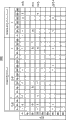
Figure 10 illustrates the adjacency histogrammic example corresponding with main histogrammic form and aspect histogram.Figure 11 illustrates the adjacency histogrammic example corresponding with main histogrammic brightness histogram.
In the adjacency histogram, as the information relevant with the distribution of adjacent pixels, system controller 107 can be from colored (" Color ") pixel extraction brightness (" Y "), saturation degree (saturation) (" colourity (Chroma) ") and form and aspect (" Hue "), and can obtain their distributions separately.In addition, system controller 107 can obtain the distribution of brightness Y based on achromaticity (" Colorless ") pixel.
In the present embodiment, the processing by in execution in step S201 and S202 has realized storage unit.More specifically, realized the example of main histogram storage unit by the processing in execution in step S201, and realized in abutting connection with the example of histogram storage unit by the processing in execution in step S202.
In the present embodiment, if the pixel of estimating is colour element, the first attribute of this pixel is form and aspect (" Hue ").On the other hand, if the pixel of estimating is non-colour element, the first attribute of this pixel is brightness (" Y ").
In the present embodiment, if the adjacent pixels of the pixel of estimating is colour element, the second attribute of this adjacent pixels comprises form and aspect (" Hue "), saturation degree (" colourity ") and brightness (" Y ").On the other hand, if the adjacent pixels of the pixel of estimating is non-colour element, the second attribute of this adjacent pixels is brightness (" Y ").
After obtaining main histogram and finish in abutting connection with histogrammic tracing object object identification processing comprising shown in the process flow diagram of Fig. 4, at step S103 (Fig. 3), system controller 107 is carried out and is used for judging whether the processing that can follow the trail of the tracing object object.
Figure 12 A and 12B are the process flow diagrams of the example of the traceability judgement processing in the step S103 that illustrates in process flow diagram shown in Figure 3.
With reference to figure 12A and 12B, in step S301 and S302, system controller 107 generates for the pixel that is present in tracing object intra-zone or outside the main histogram that comprises form and aspect histogram and brightness histogram by above with reference to figure 4, Fig. 6 A and 6B and Fig. 7 A and the described mode of 7B.
In the process flow diagram shown in Figure 12 A and 12B, the pixel count that is present in tracing object intra-zone (" inside ") of each form and aspect (" Hue ") in the form and aspect histogram 400 shown in " aHistColorTarget[m] " presentation graphs 6A.In addition, the pixel count that is present in tracing object intra-zone (" inside ") of each brightness Y in the brightness histogram 440 shown in " aHistYTarget[n] " presentation graphs 7A.In addition, the pixel count that is present in tracing object region exterior (" outside ") of each form and aspect (" Hue ") in the form and aspect histogram 400 shown in " aHistColorOther[m] " presentation graphs 6A.In addition, the pixel count that is present in tracing object region exterior (" outside ") of each brightness Y in the brightness histogram 440 shown in " aHistYOther[n] " presentation graphs 7A.In addition, system controller 107 generates the average form and aspect histogram shown in Fig. 6 B and the mean flow rate histogram shown in Fig. 7 B based on above-mentioned value.
In step S303, system controller 107 judgement is cut apart unit picture element and whether is distributed in the tracing object intra-zone by included in the form and aspect histogram.In the present embodiment, the specific form and aspect (" Hue ") in " aHistColorTarget[i] " expression of using in step S303 and form and aspect histogram 400 are the value of the corresponding pixel count that is present in tracing object intra-zone (" inside ") (i).More specifically, in step S303, system controller 107 judges aHistColorTarget[i] whether greater than 0.
If have the one or more pixels (being "Yes" in step S303) with form and aspect (i) at the tracing object intra-zone, process and enter step S304.In step S304, system controller 107 (i) calculates tracing object intra-zone or the outside ratio that exists for form and aspect (" Hue ").
With reference to as described in figure 6A and 7A, calculate the ratio that exists of tracing object intra-zone or outside form and aspect as above.More specifically, system controller 107 calculates this and has ratio by multiply by 100 divided by the result that the pixel count that is present in tracing object region exterior (" outside ") (aHistColorOther[i]) obtains for (i) the pixel count that is present in tracing object intra-zone (" inside ") of form and aspect (" Hue ") (aHistColorTarget[i]).Yet, if aHistColorTarget[i] and if 〉=1 aHistColorOther[i]=0, having ratio is 100%.
In step S305, whether system controller 107 judgements exist ratio higher than adopt the ratio of condition as predetermined form and aspect.Exist ratio not higher than the ratio that adopts condition as predetermined form and aspect (being "No" in step S305) if be judged as, being judged as the color identical with the color of tracing object object is present in background in a large number, and if carry out the tracking of using this color, the precision of following the trail of may be lower.Therefore, in step S306, in order to realize the high precision of following the trail of, system controller 107 is judged as and does not adopt form and aspect Hue to be processed (i).
On the other hand, exist ratio higher than adopt the ratio of condition as predetermined form and aspect if be judged as, process and enter step S307.In step S307, system controller 107 is judged as employing form and aspect Hue to be processed (i).
In step S308, " SumOKTarget " and " SumOKOther " of system controller 107 stores processor object form and aspect Hue (i).In the present embodiment, " SumOKTarget " expression is present in the sum of the pixel count (" aHistColorTarget[i] ") of tracing object intra-zone.In addition, in the present embodiment, " SumOKOther " expression is present in the sum of the pixel count (" aHistColorOther[i] ") of tracing object region exterior.In step S309, system controller 107 is for the processing in all form and aspect Hue (i) repeating step S303~S308.
As mentioned above, in the present embodiment, system controller 107 judge whether to adopt form and aspect histogrammic all cut apart the form and aspect Hue (i) of unit.In addition, the summation of the pixel count that adopts of system controller 107 storage.
In addition, whether system controller 107 exists ratio higher than adopt the ratio of condition as predetermined luminance for what brightness histogram judged tracing object intra-zone and outside pixel.In step S310~S316, system controller 107 judges whether to adopt the brightness Y (i) of cutting apart unit of brightness histogram.
Expression is present in " SumOKTarget " of sum of pixel of tracing object intra-zone and " SumOKOther " of sum that expression is present in the pixel of tracing object region exterior will have the pixel count of the brightness Y (i) that adopts and have the value that the summation addition of the pixel count of the form and aspect Hue (i) that adopts calculates.
Therefore, to be present in " SumOKTarget " of sum of the pixel of tracing object intra-zone be the summation with pixel count of the form and aspect Hue (i) that adopts in consequent expression.In addition, to be present in " SumOKOther " of sum of the pixel of tracing object region exterior be the summation with pixel count of the brightness Y (i) that adopts in consequent expression.
" form and aspect employing condition " and " brightness employing condition " can be set in the present embodiment, independently of one another.Especially, compare with colour, not too easily use achromaticity as the characteristic of tracing object object.Therefore, for achromaticity, adopt condition can arrange than form and aspect for brightness and adopt the stricter employing condition of condition.
In addition, though not shown, replace colored or achromatic employing condition are set, if only change the employing condition for particular color or brightness, be also useful.In addition, if the processing not in execution in step S303~S309 or the processing in step S310~S316 are also useful.
Carrying out after above-mentioned employing judgement processes by the unit of cutting apart in form and aspect histogram and brightness histogram (main histogram), process entering step S317.In step S317, the definite colour element that is present in the tracing object intra-zone that adopts of system controller 107 or the ratio of achromaticity pixel.
More specifically, system controller 107 will be by will as " SumOKTarget " of the sum of the pixel that is present in the tracing object intra-zone that adopts divided by being present on duty with 100 that pixel count in frame calculates, calculating this ratio.
In step S318, system controller 107 judges that whether this ratio is higher than condition in predetermined frame.If be judged as this ratio not higher than condition in predetermined frame (being "No" in step S318), process and enter step S319.In step S319, system controller 107 is judged as the appropriate characteristics that not yet gets the tracing object object, and can not follow the trail of this tracing object object.
On the other hand, if be judged as this ratio higher than condition in frame (being "Yes" in step S318), system controller 107 is judged as the appropriate characteristics that gets the tracing object object.Then, processing enters step S320.In step S320, system controller 107 calculates the colour element that adopts or achromaticity pixel and have a ratio in picture.
More specifically, system controller 107 calculates this ratio in the following manner.At first, system controller 107 will be as the SumOKTarget of the sum of the pixel that is present in the tracing object intra-zone and SumOKOther addition as the sum of the pixel that is present in the tracing object region exterior.Then, system controller 107 with addition result divided by the pixel count that is present in picture.Then, system controller 107 multiply by 100 with the phase division result.
In step S321, whether the ratio that system controller 107 judgements calculate in a manner described is lower than predetermined whole picture condition B.Be not less than predetermined whole picture condition B (being "No" in step S321) if be judged as this ratio, process and enter step S319.In step S319, system controller 107 is judged as: may cause tracking performance to descend owing to being present in because of the colour element that will follow the trail of in a large number or achromaticity pixel the background area that is arranged in the tracing object region exterior, therefore can not follow the trail of this tracing object object.
On the other hand, if be judged as this ratio lower than predetermined whole picture condition B (being "Yes" in step S321), process and enter step S322.In step S322, system controller 107 is judged as can follow the trail of this tracing object object.
As mentioned above, system controller 107 comprise relevant with each color and brightness single attribute evaluation process, process for the evaluation of the pixel that is present in the tracing object intra-zone and for whole picture in the evaluation of included pixel a plurality of stages of processing, judge whether to follow the trail of this tracing object object.Therefore, can be reliably according to the system controller 107 of the present embodiment and suitably judge whether and to follow the trail of the tracing object object.Yet, always do not need the whole picture evaluation in execution in step S320 and S321.
Return to Fig. 3, in step S104, the result that system controller 107 is processed based on above-described traceability judgement judges whether and can follow the trail of the tracing object zone.If be judged as and can not follow the trail of the tracing object zone (being "No" in step S104), the processing according to the process flow diagram of Fig. 3 finishes.On the other hand, can follow the trail of to the tracing object zone (being "Yes" in step S104) if be judged as, begin to follow the trail of circular treatment.
Follow the trail of in circular treatment at this, in step S105, system controller 107 judges whether to continue to follow the trail of.Figure 13 is the process flow diagram that the example of feasibility judgement processing is followed the trail of in the continuation in the step S105 that illustrates in process flow diagram shown in Figure 3.
With reference to Figure 13, in step S401, system controller 107 calculates colour element that Fig. 6 A of being present in picture and the histogram shown in 7A adopt and the ratio of achromaticity pixel.More specifically, system controller 107 by will as " SumOKALL " of the sum of the colour element that adopts in the histogram shown in Fig. 6 A and 7A and achromaticity pixel divided by pixel count included in whole picture calculate on duty with 100, calculate this ratio.In the present embodiment, the sum of pixel " SumOKALL " is the value by calculating as " SumOKTarget " of the sum of the pixel that is present in the tracing object intra-zone and " SumOKOther " addition as the sum of the pixel that is present in the tracing object region exterior.
In step S402, system controller 107 judges that whether this ratio is lower than predetermined whole picture condition C.Be not less than predetermined whole picture condition C (being "No" in step S402) if be judged as this ratio, process and enter step S403.In step S403, system controller 107 is judged as: may cause tracking performance to descend owing to being present in because of the colour element that will follow the trail of in a large number or achromaticity pixel the background area that is arranged in the tracing object region exterior, therefore can not follow the trail of the tracing object object.
On the other hand, if be judged as this ratio lower than predetermined whole picture condition C (being "Yes" in step S402), process and enter step S404.In step S404, system controller 107 is judged as and can follows the trail of the tracing object object.In the present embodiment, " whole picture condition C " can be set to the condition different from " whole picture condition B ", wherein this whole picture condition B is used for judging whether with reference to the processing in the described step S321 of figure 12B the final Rule of judgment that can follow the trail of the tracing object object as above.
By using the whole picture condition C stricter than whole picture condition B, can the situation of background change after following the trail of beginning according to the system controller 107 of the present embodiment, when the pixel count that has thus the form and aspect identical with the form and aspect of tracing object object or brightness or brightness increases, judge whether to suspend immediately tracking.
In the example depicted in fig. 13, condition is fixed as whole picture condition C.Yet, if condition changes (becoming sternly) gradually according to institute's elapsed time after the tracking beginning, be also useful.
In addition, if for only following the trail of object, only follow the trail of object based on brightness and the two follows the trail of the various situations of object based on form and aspect and brightness based on form and aspect, " the whole picture condition C " used in " whole picture condition B " (Figure 12 B) that use in " frame in condition " (Figure 12 B), the step S321 that uses in step S318 and step S402 (Figure 13) become sternly, is also useful.In addition, if further change only for the condition of particular color with only for the condition of certain luminance, be also useful.
Return to Fig. 3, in step S106, system controller 107 is based on the result of continue following the trail of the feasibility judgement and processing, and judges whether to continue the tracing object zone is followed the trail of.Can not continue (being "No" in step S106) followed the trail of in the tracing object zone if be judged as, the processing shown in the process flow diagram of Fig. 3 finishes.On the other hand, can continue (being "Yes" in step S106) followed the trail of in the tracing object zone if be judged as, process and enter step S107.In step S107, system controller 107 is carried out the tracing object object detection and is processed.
Figure 14 is the process flow diagram of the example of the tracing object object detection processing in the step S107 that illustrates in process flow diagram shown in Figure 3.Can carry out the processing of tracing object object detection on the arbitrary region in this picture on whole picture or only.Yet, in the present embodiment, suppose that carrying out the tracing object object detection on whole picture processes.
Figure 15 schematically shows for process the example of the method that the tracing object zone is followed the trail of by carrying out the tracing object object detection.Various starting points, direction or order can be set when in picture, the tracing object object being followed the trail of.Yet, in the present embodiment, suppose as shown in figure 15, begin flatly to carry out the tracking of tracing object object from the upper left of picture.Then, following row is carried out tracking in turn.
With reference to Figure 14, in step S501, system controller 107 judges whether pixel to be processed (pixel that will estimate) and the pixel that is distributed in histogram mate.More specifically, in step S501, system controller 107 judges that whether pixel to be processed is as colour element or the achromaticity pixel of storing in the pixel that is present in the tracing object intra-zone, main histogram shown in Fig. 6 A and 7A.In addition, in step S501, system controller 107 judges whether pixel to be processed has mean flow rate, average staturation or the average form and aspect that have been stored in preset range in the average histogram shown in Fig. 6 B and 7B, that fall into this average histogram.
Do not mate (being "No" in step S501) if be judged as pixel to be processed with the pixel that is distributed in main histogram, process and enter step S506.On the other hand, if be judged as pixel to be processed and the pixel matching (being "Yes" in step S501) that is distributed in main histogram, process and enter step S502.In step S502, the position allocation fixed-point number (rating point) of 107 pairs of these pixels of system controller.
Figure 16 A~16D schematically shows for to the pixel allocation fixed-point number that will the search for example with the method that detects the tracing object object.With reference to figure 16A, if the Color matching in pixel to be processed (processing object pixel) 650 and main histogram, 107 pairs of system controllers are processed 1 specified counting of object pixel 650 distribution.
On the other hand, as shown in Figure 16 B, if process achromaticity coupling in object pixel 660 and main histogram, 107 pairs of system controllers are processed object pixel 660 and are distributed 0 and count (not to processing object pixel 660 allocation fixed-point numbers).
Alternatively, it is also useful adopting following structure.More specifically, in this case, if the Color matching in processing object pixel 650 and main histogram, 107 pairs of system controllers are processed 2 specified counting of object pixel 650 distribution.On the other hand, in this case, if process achromaticity coupling in object pixel 650 and main histogram, system controller 107 distributes 1 and counts, and this is counted is than in the situation that specified little specified the counting of counting that colour distributes.
In step S503, whether the adjacent pixels that object pixel are processed in system controller 107 judgement mates with the pixel that is distributed in the histogram.More specifically, for the pixel of main Histogram Matching, system controller 107 judgements are present in whether mating in abutting connection with histogram shown in 8 pixels processing around object pixel 610 and Figure 10 and 11.
Do not mate (being "No" in step S503) if be judged as the adjacent pixels of processing object pixel with the pixel that is distributed in the histogram, process and enter step S505.On the other hand, if be judged as the adjacent pixels of processing object pixel and the pixel matching (being "Yes" in step S503) that is distributed in the histogram, process and enter step S504.In step S504, the position allocation fixed-point number of 107 pairs of these pixels of system controller.
More specifically, as shown in Figure 16 C, if the colour element 652 that is distributed in histogram and has form and aspect different from the form and aspect of the colour element that is complementary with the colour in main histogram with should be adjacent with the colour element that the colour in main histogram is complementary, system controller 107 distributes 5 and counts.
On the other hand, as shown in Figure 16 C, if the colour element 654 that is distributed in histogram and has form and aspect identical with the form and aspect of the colour element that is complementary with the colour in main histogram with should be adjacent with the colour element that the colour in main histogram is complementary, system controller 107 distributes 4 and counts.
In addition, as shown in Figure 16 C, if the achromaticity pixel 656 that is distributed in the histogram is adjacent with the colour element that is complementary with the colour in main histogram, system controller 107 distributes 3 and counts.
On the other hand, as shown in Figure 16 D, if the colour element 662 that is distributed in the histogram is adjacent with the achromaticity pixel that is complementary with the achromaticity in main histogram, system controller 107 distributes 3 and counts.
In addition, as shown in Figure 16 D, if the achromaticity pixel of the brightness that the brightness of the achromaticity pixel that has and be complementary with the achromaticity in main histogram is different 664 was adjacent with the achromaticity pixel that the achromaticity in main histogram is complementary with this, system controller 107 2 of distribution are counted.On the other hand, as shown in Figure 16 D, if the achromaticity pixel of the brightness that the brightness of the achromaticity pixel that has and be complementary with the achromaticity in main histogram is identical 666 was adjacent with the achromaticity pixel that the achromaticity in main histogram is complementary with this, system controller 107 2 of distribution are counted.
Whether when being distributed in the arbitrary pixel in the histogram shown in Figure 10 and 11 and being complementary, if this adjacent pixels is colour element, if only carry out judgement based on form and aspect, be also useful in adjacent pixels that object pixel is processed in judgement.Alternatively, in this case, if carry out judgement based on all form and aspect, saturation degree (" colourity ") and brightness Y, be also useful.
In the example shown in Figure 16 A~16D, the rated point that distribute is several according to processing object pixel and changing with the combination of the pixel of this processing object pixel adjacency.Yet, if distribute identical specified counting under above-mentioned all situations, be also useful.In addition, if distribute and above-mentioned specified different specified the counting of counting, be also useful.
In the tracing object object detection is processed, system controller 107 judgements process object pixel whether be distributed in that arbitrary pixel in main histogram is complementary and whether be complementary with the arbitrary pixel that is distributed in the histogram with the pixel of processing the object pixel adjacency.
In above-mentioned judgement, system controller 107 do not use with main histogram and in the histogram the relevant information of included pixel count.Therefore, can be from main histogram and the deletion information relevant with pixel count in abutting connection with histogram.More specifically, in the tracing object object detection is processed, need following information: the information that the attribute that has with each pixel included in the tracing object zone is relevant and with the tracing object zone in the relevant information of the attribute that has of each adjacent pixels of included each pixel.
In other words, in the tracing object object detection is processed, need following information: the information that the attribute that has with pixel included in the tracing object zone is relevant and with the tracing object zone in the relevant information of the attribute that has of the adjacent pixels of included each pixel.
If the grouped data that the tracing object object detection is used in processing can comprise above-mentioned information, this grouped data is not limited to the main histogram shown in Fig. 6 A and 6B and Fig. 7 A and 7B.In addition, having the Main classification data of the form different from above-described form if use, is also useful.
In addition, in abutting connection with grouped data be not limited to shown in Figure 10 and 11 in abutting connection with histogram.More specifically, if use have the form different from above-described form in abutting connection with grouped data, be also useful.More specifically, replace generating and use the main histogram shown in Fig. 6 A and 6B and Fig. 7 A and 7B, if the Main classification data of the type of the form and aspect that the pixel that generates and use only expression to be present in the tracing object intra-zone has are also useful.
In addition, replace generating and to use shown in Figure 10 or 11 in abutting connection with histogram, if the type of the form and aspect that the pixel that system controller 107 only generates and use expression to be present in the tracing object intra-zone has and be adjacent to the form and aspect that all pixels of this pixel have separately type in abutting connection with grouped data, be also useful.
As above with reference to as described in Figure 15 and Figure 16 A~16D, in the present embodiment, system controller 107 estimate the pixel to be processed that is present in picture and and the pixel of this pixel adjacency between relation.In addition, system controller 107 judgement is processed matching state between object pixel and main histogram and adjacent pixels and in abutting connection with the matching state between histogram.Be complementary each other if be judged as them, the position allocation fixed-point number of 107 pairs of pixels of estimating of system controller.In step S505, system controller 107 judges whether all adjacent pixels to have been carried out above-mentioned processing fully.
If be judged as all adjacent pixels carried out above-mentioned processing (being "Yes" in step S505) fully, process and enter step S506.In step S506, system controller 107 by use distribute specified count and main histogrammic mean flow rate, average staturation and the average color of respectively cutting apart unit mutually, to each position calculation evaluation of estimate of the pixel estimated, wherein mean flow rate, average staturation and average color have been stored mutually by above with reference to the described mode of figure 6B and 7B.
More specifically, if the pixel of estimating is colour element, system controller 107 uses following formulas (1) to calculate evaluation of estimate, and if the pixel of estimating is non-colour element, system controller 107 uses following formulas (2) to calculate evaluation of estimate:
wherein, the form and aspect of the pixel estimated of " Δ Hue " expression and be stored in poor between average form and aspect in the average histogram shown in Fig. 6 B and 7B, the saturation degree of the pixel estimated of " Δ Chroma " expression and before be stored in poor between average staturation in the average histogram shown in Fig. 6 B and 7B, the brightness of the pixel estimated of " Δ Y " expression and before be stored in poor between mean flow rate in the average histogram shown in Fig. 6 B and 7B, and " Δ Distance " be expressed as follows the position of frame and the position of the pixel estimated between distance, wherein this frame table shows the position by the shown tracing object object of display device 105.If it is high to detect the precision of tracing object object, distance " Δ Distance " is unnecessary, and perhaps " Δ Distance " can be very little.
Yet, have in a large number the pixel of similar form and aspect or brightness if exist around the pixel of estimating, can suppress by the item that the specific range coefficient is added into expression formula (1) and (2) hunting (hunting) phenomenon of the demonstration of contingent frame due to the low precision that detects the tracing object object.
In expression formula (1) and (2), with the item addition each other of different system of units.Therefore, in order to keep the balance between them, coefficient of performance " K0 "~" K4 ".Alternatively, in order to simplify processing, if use constant as expression formula (1) and (2) denominator separately, be also useful.This be because: if the standard of the judgement in step S501 is set to strictly, the variation range of the value of " the Δ Hue " and " Δ Chroma " in expression formula (1) and (2) denominator separately diminishes.
In step S507, system controller 107 judges whether to complete the calculating to the evaluation of estimate that is present in all pixels in picture.If be judged as the calculating (being "No" in step S507) of not yet completing the evaluation of estimate that is present in all pixels in picture, process and be back to step S501.On the other hand, if be judged as the calculating (being "Yes" in step S507) of completing the evaluation of estimate that is present in all pixels in picture, process and enter step S508.
In step S508, the evaluation of estimate that system controller 107 use calculate is identified the position of tracing object object.More specifically, if the evaluation of estimate that system controller 107 search calculates reaches the position of its peak value take pixel as unit, and this position is set to the position of tracing object object, is also useful.In addition, if system controller 107 search has the position of set of the pixel of the evaluation of estimate higher than predetermined value, and the position of the set of these pixels is set to the position of tracing object object, is also useful.
Yet, if can not determine out that this evaluation of estimate reaches the position of particular value, if the evaluation of estimate that namely calculates by use can not identify the position of tracing object object, the position of system controller 107 nonrecognition tracing object objects.
If identified the position of tracing object object, system controller 107 is identified for the position of display box according to the position of the tracing object object that identifies.If not yet identify the position of tracing object object, the uncertain position for display box of system controller 107.
In the present embodiment, by carrying out the processing in above-described step S502, S504 and S506, realized the example of allocation units.In addition, in the present embodiment, by the processing in execution in step S508 and S509, realized changing the example of unit.
Figure 17 illustrates the example of the result of calculation of evaluation of estimate.In example shown in Figure 17, show at image and become the evaluation of estimate of the image shown in situation figure below 2B of the image shown in Fig. 2 B from the image shown in Fig. 2 A.
In example shown in Figure 17, the longitudinal axis and transverse axis be the image coordinate in vertical direction shown in presentation graphs 2B and this image coordinate in the horizontal direction respectively.The evaluation of estimate that represents each coordinate place perpendicular to another axle on the plane parallel with this diaxon.
In the example shown in Fig. 2 A, show the image when determining the tracing object object.System controller 107 is identified as the tracing object zone with the parts of zone in 202.In addition, system controller 107 generates the main histogram in this tracing object zone and in abutting connection with histogram.
In the example shown in Fig. 2 B, show the tracing object zone image after mobile.The evaluation of estimate that calculates under this state has distribution shown in Figure 17.As a result, system controller 107 can show the frame in expression tracing object zone in the zone with high evaluation value 612.
In the present embodiment, in example shown in Figure 17, exist to have the high evaluation value 620 that is different from evaluation of estimate 612, a plurality of zones of 622 and 624.
The frame of supposing the current shown tracing object of expression zone is present in the position with evaluation of estimate 620.Evaluation of estimate 620 is lower than evaluation of estimate 612.In addition, have evaluation of estimate 620 pixel the position from the pixel with evaluation of estimate 612 close to.Therefore, may frame be presented on this tracing object object.
Therefore, in this case, if system controller 107 does not change the position that shows this frame, be also useful.More specifically, replacing the position of evaluation of estimate 612 is changed in the position, if this frame is presented at the position of evaluation of estimate 620, is also useful.
Return to Fig. 3, in step S108, system controller 107 judgement is as the result of step S508 shown in Figure 14, the tracing object zone whether detected.Tracing object zone (being "Yes" in step S108) detected if be judged as, process and enter step S109.In step S109, the frame display position place display box of determining in the step S509 of system controller 107 in Figure 14.Then, processing is back to step S105.
On the other hand, if tracing object zone (being "No" in step S108) do not detected, process and enter step S110.In step S110, whether that system controller 107 judges whether to occur is overtime (that is, passing through the schedule time the moment that the tracing object zone do not detected from being judged as).
If be judged as, overtime (in step S110 for "Yes") occuring, finishes the processing shown in the process flow diagram of Fig. 3.On the other hand, if be judged as, overtime (being "No" in step S110) occuring not, processes and be back to step S105.
As mentioned above, in the present embodiment, system controller 107 generates the histogram (main histogram) as the Main classification data that the pixel classification that is present in tracing object intra-zone or outside is obtained.More specifically, for colour, system controller 107 generates form and aspect histogram 400.For achromaticity, system controller 107 generates brightness histogram 440.In addition, for each pixel that is present in the tracing object intra-zone, system controller 107 generates the histogram 500 and 520 (in abutting connection with histogram) in abutting connection with grouped data that obtains as to the pixel classification with this pixel adjacency.
When detecting the tracing object object, if there is the pixel with the attribute of answering with the Attribute Relative of processing object pixel in main histogram, system controller 107 increases the evaluation of estimate that this processes object pixel.On the other hand, if having the pixel with the attribute of answering with the Attribute Relative of the adjacent pixels of processing object pixel in histogram, system controller 107 increases the evaluation of estimate that this processes object pixel.
For the adjacency histogram, the present embodiment only judges the attribute of the adjacent pixels of processing object pixel, and does not judge that adjacent pixels is with respect to the orientation of processing object pixel.Therefore, if the orientation of tracing object object changes because of rotation, if perhaps tracing equipment (picture pick-up device) self in the vertical direction or the posture on horizontal direction change, may be not easy to affect evaluation of estimate.
By using in abutting connection with histogram, the present embodiment judgement is processed the attribute of the pixel of object pixel adjacency with each.Therefore, even the shape of tracing object object self is out of shape, the present embodiment still can improve tracking performance.
More specifically, if the personage's of look straight ahead face is set to the tracing object object, and if this tracing object object (personage's face) tilts towards the side, the width of the image of this personage's face reduces.Therefore, in this case, the shape the when face that the shape of the image of personage's face may be different from this personage is set to the tracing object object.
In addition, if the personage's of look straight ahead face is set to the tracing object object, and if this personage near tracing equipment, the size when the size of the image of personage's the face face that may be different from this personage is set to the tracing object object.
For example, pay close attention to the pixel corresponding with personage's canthus, and the corresponding pixel of the outer rim of the iris of eyes and pixel this three pixels corresponding with labial angle.In this example, if the orientation of personage's face changes, if perhaps personage's face is near tracing equipment, the direction relations between these three pixels and the relative distance between them change.Yet, in this case, easily understand the attribute of each pixel and less with the variable quantity of the attribute of the pixel of this pixel adjacency.
In the present embodiment, in 107 pairs of pictures of system controller, all included pixels are carried out above-mentioned evaluation of estimate calculating.In addition, system controller 107 will comprise that the region division of the pixel with high evaluation value is the tracing object zone.
Utilize said structure, can not carry out at traditional method for tracing under the state of suitable tracking operation, the present embodiment can improve tracking performance.
In addition, the present embodiment that has a said structure need not to store the template image of following the trail of use.Therefore, can save memory capacity.In addition, in the situation that image resolution ratio is low, the present embodiment can improve tracking performance.Therefore, the present embodiment does not need high image handling property.
Below, will describe second embodiment of the invention in detail.In the present embodiment, if can utilize frame differential method, by frame differential method, the tracing object object is followed the trail of.On the other hand, in the present embodiment, if can not utilize frame differential method to follow the trail of, by the tracing object object being followed the trail of in the similar mode of mode described in the first embodiment with above.
In other words, the difference of the present embodiment and above-mentioned the first embodiment is: the present embodiment uses frame differential method.The assembly that utilizes the Reference numeral identical with above Reference numeral with reference to described the first embodiment of figure 1~17 or symbol or symbol that the present embodiment identical with the assembly of the first embodiment is set.Therefore, will not repeat explanation to these assemblies here.
Figure 18 illustrates the main flow chart that is used for the example of processing that the tracing object object is followed the trail of by performed according to the picture pick-up device of the present embodiment.
With reference to Figure 18, in step S1001, system controller 107 is determined position and the size of tracing object object.In step S1002, system controller 107 is carried out the tracing object object identification and is processed.In step S1003, system controller 107 is carried out the traceability judgement and is processed.In step S1001~S1003, system controller 107 is carried out the identical processing of processing in the step S101 shown in process flow diagram with Fig. 3~S103.
In step S1004, system controller 107 is by using interframe relative mistake point-score that the tracing object zone is followed the trail of.During interframe relative mistake point-score, system controller 107 uses the view data that is present in specified trace location place as template image, and search will be carried out the zone of pattern match from picture frame subsequently.
In addition, system controller 107 view data that will be present in the position that is detected as the zone that will carry out pattern match is updated to template image.In addition, system controller 107 continues to search for the zone that will carry out pattern match from two field picture subsequently.
As mentioned above, in the present embodiment, system controller 107 continues from two field picture subsequently, the tracing object object to be followed the trail of when upgrading template image in turn.When using interframe relative mistake point-score, can not execution pattern mate, and be judged as in some cases and can not follow the trail of the tracing object object.
Therefore, in step S1005, system controller 107 judges whether to utilize interframe relative mistake point-score to follow the trail of.More specifically, if the orientation of tracing object object is because it rotates flip-flop, if perhaps tracing equipment self in the vertical direction or the posture on horizontal direction change, and if due to these former thereby cause can not execution pattern coupling, can not utilize interframe relative mistake point-score to follow the trail of.
Can utilize interframe relative mistake point-score to follow the trail of (being "Yes" in step S1005) if be judged as, process and be back to step S1004, and system controller 107 continue by interframe relative mistake point-score, the tracing object object to be followed the trail of.On the other hand, can not utilize interframe relative mistake point-score to follow the trail of (being "No" in step S1005) if be judged as, process and enter step S1006.
In this case, in step S1006, system controller 107 is carried out and is continued to follow the trail of feasibility judgement processing.In step S1007, system controller 107 judges whether can continue the tracing object object is followed the trail of.In step S1008, system controller 107 is carried out the tracing object object detection and is processed.More specifically, in step S1009, system controller 107 judges whether to detect the tracing object object.
Tracing object object (being "Yes" in step S1009) detected if be judged as, process and enter step S1010.In step S1010, system controller 107 is presented at frame display position place with frame.Then, processing is back to step S1004.
In step S1004, system controller 107 restarts by interframe relative mistake point-score, the tracing object object to be followed the trail of from the tracing object zone that detects step S1008.On the other hand, if the tracing object zone not yet detected, process and enter step S1011.In step S1011, system controller 107 judges whether to occur overtime.If be judged as, overtime (being "Yes" in step S1011) occuring, finishes the processing according to the process flow diagram of Figure 18.On the other hand, if be judged as, overtime (being "No" in step S1011) occuring not yet, processes and be back to step S1006.
Processing in step S1006~S1011 is identical with the processing in the step S105 shown in the process flow diagram of Fig. 3~S110.
As mentioned above, in the processing according to process flow diagram shown in Figure 180, carry out simultaneously the tracking utilize interframe relative mistake point-score and above in the tracking described in the first embodiment.Yet the present invention is not limited to this.More specifically, carrying out simultaneously if process parallel ground with these two, is also useful.In this case, the precision of which processing of system controller 107 judgement is high, and the result of the higher processing of service precision is carried out the tracking to the tracing object object.In addition, replacing interframe relative mistake point-score, if use such as above any other method for tracing in the method described in background technology etc., is also useful.
In addition, can also store for the storage medium (or recording medium) of the program code of the software of the function that realizes each embodiment and read and carry out by the computing machine (CPU or MPU) that utilizes this system or device the program code that this storage medium is stored by providing to system or device, realize the present invention.In this case, the program code self that reads from storage medium has been realized the function of the various embodiments described above.In addition, can will realize that the procedure stores of the embodiment of the present invention is on computer-readable recording medium.
Although with reference to each embodiment, the present invention has been described, should be appreciated that, the invention is not restricted to the disclosed embodiments.The scope of appended claims meets the widest explanation, to comprise all these class modifications, equivalent structure and function.
Claims (12)
1. image processing equipment comprises:
Storage unit, be used for being present in the tracing object zone that is arranged on image inside each pixel attribute and with the attribute of the pixel of this pixel adjacency;
Allocation units, be used for according to the attribute of the pixel that will estimate and be present between the attribute of pixel of inside in described tracing object zone comparative result and and the attribute of the pixel of the described pixel adjacency that will estimate and and be present in comparative result between the attribute of pixel of pixel adjacency of inside in described tracing object zone, to the described pixel allocation evaluation value that will estimate; And
Change the unit, be used for based on the evaluation of estimate of distributing, change described tracing object regional;
Described storage unit comprises:
The Main classification unit, be used for generating the Main classification data, and described Main classification data are stored on storage medium, wherein said Main classification data are as the grouped data of each pixel of the inside that is present in described tracing object zone, data that obtain according to predtermined category unit's classification of the first attribute; And
In abutting connection with taxon, be used for generating in abutting connection with grouped data, and be stored on storage medium in abutting connection with grouped data described, wherein said in abutting connection with grouped data be as with the grouped data of the pixel of each pixel adjacency of the inside that is present in described tracing object zone, data that obtain according to predtermined category unit's classification of the predtermined category unit of described the first attribute and the second attribute
Wherein, if be registered in described Main classification data with at least one corresponding pixel of described the first attribute, and if be registered in describedly in grouped data with at least one corresponding pixel of at least one and described the second attribute of described the first attribute, described allocation units are to the described pixel allocation evaluation value that will estimate.
2. image processing equipment according to claim 1, it is characterized in that, if be registered in describedly in grouped data with at least one corresponding pixel of at least one and described the second attribute of described the first attribute, described allocation units change the evaluation of estimate that will be dispensed to the described pixel that will estimate according to the attribute of the described pixel that will estimate with the combination of the attribute of the pixel of the described pixel adjacency that will estimate.
3. image processing equipment according to claim 2, it is characterized in that, if be registered in described in grouped data with at least one of described the first attribute and at least one corresponding pixel of described the second attribute, and the described pixel that will estimate is colour element, described allocation units distribute high evaluation value by descending to the described pixel that will estimate for following three kinds of situations: be the situation of the colour element different with the described pixel that will estimate from the pixel of the described pixel adjacency that will estimate, the situation of the colour element identical with the described pixel that will estimate with the pixel of the described pixel adjacency that will estimate, and with the pixel of the described pixel adjacency that will estimate be the situation of non-colour element.
4. image processing equipment according to claim 2, it is characterized in that, if be registered in described in grouped data with at least one of described the first attribute and at least one corresponding pixel of described the second attribute, and the described pixel that will estimate is non-colour element, described allocation units distribute high evaluation value by descending to the described pixel that will estimate for following three kinds of situations: with the pixel of the described pixel adjacency that will estimate be the situation of colour element, the situation with achromaticity pixel of the brightness different with the brightness of the described pixel that will estimate from the pixel of the described pixel adjacency that will estimate, and be the situation with achromaticity pixel of the luminance level identical with the described pixel that will estimate with the pixel of the described pixel adjacency that will estimate.
5. image processing equipment according to claim 1, is characterized in that, if the described pixel that will estimate is colour element, described the first attribute is form and aspect, if the described pixel that will estimate is non-colour element, described the first attribute is brightness.
6. image processing equipment according to claim 1, it is characterized in that, if with the pixel of the described pixel adjacency that will estimate be colour element, described the second attribute is form and aspect, saturation degree and brightness, if with the pixel of the described pixel adjacency that will estimate be non-colour element, described the second attribute is brightness.
7. image processing equipment according to claim 1, it is characterized in that, described Main classification data are the histograms that obtain according to the classification of the predtermined category unit of described the first attribute, and described be the histogram that the predtermined category unit's classification according to the predtermined category unit of described the first attribute and described the second attribute obtains in abutting connection with grouped data.
8. image processing method comprises:
Storing step, be used for being present in the tracing object zone that is arranged on image inside each pixel attribute and with the attribute of the pixel of this pixel adjacency;
Allocation step, be used for according to the attribute of the pixel that will estimate and be present between the attribute of pixel of inside in described tracing object zone comparative result and and the attribute of the pixel of the described pixel adjacency that will estimate and and be present in comparative result between the attribute of pixel of pixel adjacency of inside in described tracing object zone, to the described pixel allocation evaluation value that will estimate; And
Change step, be used for based on the evaluation of estimate of distributing, change described tracing object regional;
Described storing step comprises:
Generate the Main classification data, and described Main classification data are stored on storage medium, wherein said Main classification data are as the grouped data of each pixel of the inside that is present in described tracing object zone, data that obtain according to predtermined category unit's classification of the first attribute; And
Generation is in abutting connection with grouped data, and be stored on storage medium in abutting connection with grouped data described, wherein said in abutting connection with grouped data be as with the grouped data of the pixel of each pixel adjacency of the inside that is present in described tracing object zone, data that obtain according to predtermined category unit's classification of the predtermined category unit of described the first attribute and the second attribute;
If be registered in described Main classification data with at least one corresponding pixel of described the first attribute, and if with at least one corresponding pixel of at least one and described the second attribute of described the first attribute be registered in described in grouped data, to the described pixel allocation evaluation value that will estimate.
9. image processing method according to claim 8, is characterized in that, also comprises:
If be registered in describedly in grouped data with at least one corresponding pixel of at least one and described the second attribute of described the first attribute, change the evaluation of estimate that will be dispensed to the described pixel that will estimate according to the attribute of the described pixel that will estimate with the combination of the attribute of the pixel of the described pixel adjacency that will estimate.
10. image processing method according to claim 8, is characterized in that, if the described pixel that will estimate is colour element, described the first attribute is form and aspect, if the described pixel that will estimate is non-colour element, described the first attribute is brightness.
11. image processing method according to claim 8, it is characterized in that, if with the pixel of the described pixel adjacency that will estimate be colour element, described the second attribute is form and aspect, saturation degree and brightness, if with the pixel of the described pixel adjacency that will estimate be non-colour element, described the second attribute is brightness.
12. image processing method according to claim 8, it is characterized in that, described Main classification data are the histograms that obtain according to the classification of the predtermined category unit of described the first attribute, and described be the histogram that the predtermined category unit's classification according to the predtermined category unit of described the first attribute and described the second attribute obtains in abutting connection with grouped data.
Applications Claiming Priority (2)
| Application Number | Priority Date | Filing Date | Title |
|---|---|---|---|
| JP2009-183629 | 2009-08-06 | ||
| JP2009183629A JP5279653B2 (en) | 2009-08-06 | 2009-08-06 | Image tracking device, image tracking method, and computer program |
Publications (2)
| Publication Number | Publication Date |
|---|---|
| CN101996408A CN101996408A (en) | 2011-03-30 |
| CN101996408B true CN101996408B (en) | 2013-06-05 |
Family
ID=43063604
Family Applications (1)
| Application Number | Title | Priority Date | Filing Date |
|---|---|---|---|
| CN201010250263XA Expired - Fee Related CN101996408B (en) | 2009-08-06 | 2010-08-06 | Image processing apparatus and image processing method |
Country Status (5)
| Country | Link |
|---|---|
| US (1) | US8503723B2 (en) |
| EP (1) | EP2282224B1 (en) |
| JP (1) | JP5279653B2 (en) |
| KR (1) | KR101321780B1 (en) |
| CN (1) | CN101996408B (en) |
Families Citing this family (7)
| Publication number | Priority date | Publication date | Assignee | Title |
|---|---|---|---|---|
| CN102129678A (en) * | 2010-01-12 | 2011-07-20 | 鸿富锦精密工业(深圳)有限公司 | Image characteristic model establishment system, method and image processing system using system and method |
| US10423858B2 (en) | 2014-07-21 | 2019-09-24 | Ent. Services Development Corporation Lp | Radial histogram matching |
| US9805662B2 (en) * | 2015-03-23 | 2017-10-31 | Intel Corporation | Content adaptive backlight power saving technology |
| US11336831B2 (en) * | 2018-07-06 | 2022-05-17 | Canon Kabushiki Kaisha | Image processing device, control method, and program storage medium |
| CN114430457B (en) * | 2020-10-29 | 2024-03-08 | 北京小米移动软件有限公司 | Shooting method, shooting device, electronic equipment and storage medium |
| JP7117593B1 (en) * | 2021-07-08 | 2022-08-15 | パナソニックIpマネジメント株式会社 | Imaging device |
| US11917293B2 (en) | 2021-07-08 | 2024-02-27 | Panasonic Intellectual Property Management Co., Ltd. | Imaging device |
Citations (1)
| Publication number | Priority date | Publication date | Assignee | Title |
|---|---|---|---|---|
| CN101147159A (en) * | 2005-02-21 | 2008-03-19 | 三菱电机株式会社 | Fast method of object detection by statistical template matching |
Family Cites Families (8)
| Publication number | Priority date | Publication date | Assignee | Title |
|---|---|---|---|---|
| US6160900A (en) * | 1994-02-04 | 2000-12-12 | Canon Kabushiki Kaisha | Method and apparatus for reducing the processing time required in motion vector detection |
| US6072889A (en) * | 1997-12-03 | 2000-06-06 | The Raytheon Company | Method and system for imaging target detection |
| JP3630569B2 (en) * | 1998-10-23 | 2005-03-16 | 株式会社東芝 | Image area tracking method and apparatus |
| US6700999B1 (en) * | 2000-06-30 | 2004-03-02 | Intel Corporation | System, method, and apparatus for multiple face tracking |
| JP3836814B2 (en) * | 2003-05-20 | 2006-10-25 | 株式会社東芝 | Image processing method, image processing apparatus, and image processing program |
| JP2009522591A (en) * | 2005-12-30 | 2009-06-11 | ノキア コーポレイション | Method and apparatus for controlling autofocus of a video camera by tracking a region of interest |
| DE102007061935A1 (en) * | 2007-12-21 | 2009-06-25 | Siemens Aktiengesellschaft | Method for improving the quality of computed tomographic image series by image processing and CT system with arithmetic unit |
| JP5279654B2 (en) * | 2009-08-06 | 2013-09-04 | キヤノン株式会社 | Image tracking device, image tracking method, and computer program |
-
2009
- 2009-08-06 JP JP2009183629A patent/JP5279653B2/en not_active Expired - Fee Related
-
2010
- 2010-07-14 EP EP10169567.4A patent/EP2282224B1/en not_active Not-in-force
- 2010-07-30 KR KR1020100073755A patent/KR101321780B1/en active IP Right Grant
- 2010-08-02 US US12/848,908 patent/US8503723B2/en not_active Expired - Fee Related
- 2010-08-06 CN CN201010250263XA patent/CN101996408B/en not_active Expired - Fee Related
Patent Citations (1)
| Publication number | Priority date | Publication date | Assignee | Title |
|---|---|---|---|---|
| CN101147159A (en) * | 2005-02-21 | 2008-03-19 | 三菱电机株式会社 | Fast method of object detection by statistical template matching |
Non-Patent Citations (1)
| Title |
|---|
| JP特开2004-348273A 2004.12.09 |
Also Published As
| Publication number | Publication date |
|---|---|
| CN101996408A (en) | 2011-03-30 |
| EP2282224B1 (en) | 2017-01-11 |
| KR20110014960A (en) | 2011-02-14 |
| EP2282224A2 (en) | 2011-02-09 |
| KR101321780B1 (en) | 2013-10-25 |
| US20110033085A1 (en) | 2011-02-10 |
| EP2282224A3 (en) | 2011-10-05 |
| JP5279653B2 (en) | 2013-09-04 |
| JP2011039596A (en) | 2011-02-24 |
| US8503723B2 (en) | 2013-08-06 |
Similar Documents
| Publication | Publication Date | Title |
|---|---|---|
| CN101996409B (en) | Image processing apparatus and image processing method | |
| CN101996408B (en) | Image processing apparatus and image processing method | |
| CN107016367B (en) | Tracking control method and tracking control system | |
| CN102629977B (en) | Image display controller, image control apparatus, method of controlling the image display controller | |
| US9098769B2 (en) | Method and a device for objects counting | |
| CN1909603B (en) | Image processing method and imaging apparatus | |
| CN102103754B (en) | Subject tracking apparatus, subject region extraction apparatus, and control methods therefor | |
| EP2549738B1 (en) | Method and camera for determining an image adjustment parameter | |
| CN107258077B (en) | System and method for Continuous Auto Focus (CAF) | |
| CN102843509B (en) | Image processing device and image processing method | |
| CN1328700C (en) | Intelligent traffic system | |
| CN102342090A (en) | Image capturing device, operator monitoring device, method for measuring distance to face, and program | |
| CN108234874B (en) | Method and device for adjusting imaging precision of somatosensory camera | |
| CN108986097A (en) | A kind of camera lens hazes condition detection method, computer installation and readable storage medium storing program for executing | |
| US20180047184A1 (en) | Image processing apparatus for processing images captured by a plurality of imaging units, image processing method, and storage medium storing program therefor | |
| US11694433B2 (en) | Detection of projected infrared patterns using difference of Gaussian and blob identification | |
| CN106991378A (en) | Facial orientation detection method, detection means and electronic installation based on depth | |
| CN111598065A (en) | Depth image acquisition method, living body identification method, apparatus, circuit, and medium | |
| CN106600628A (en) | Target object identification method and device based on infrared thermal imaging system | |
| CN102270298B (en) | Method and device for detecting laser point/area | |
| JP2006065447A (en) | Discriminator setting device, degree-of-attention measuring device, discriminator setting method, degree-of-attention measuring method, and program | |
| CN106970709B (en) | 3D interaction method and device based on holographic imaging | |
| CN108885265A (en) | Range image processing unit, range image acquisition device and range image processing method | |
| US20090087088A1 (en) | Image forming system, apparatus and method of discriminative color features extraction thereof | |
| CN113936316B (en) | DOE (DOE-out-of-state) detection method, electronic device and computer-readable storage medium |
Legal Events
| Date | Code | Title | Description |
|---|---|---|---|
| C06 | Publication | ||
| PB01 | Publication | ||
| C10 | Entry into substantive examination | ||
| SE01 | Entry into force of request for substantive examination | ||
| C14 | Grant of patent or utility model | ||
| GR01 | Patent grant | ||
| CF01 | Termination of patent right due to non-payment of annual fee |
Granted publication date: 20130605 Termination date: 20200806 |
|
| CF01 | Termination of patent right due to non-payment of annual fee |