CN101897234B - Cooking device - Google Patents
Cooking device Download PDFInfo
- Publication number
- CN101897234B CN101897234B CN200880120818.XA CN200880120818A CN101897234B CN 101897234 B CN101897234 B CN 101897234B CN 200880120818 A CN200880120818 A CN 200880120818A CN 101897234 B CN101897234 B CN 101897234B
- Authority
- CN
- China
- Prior art keywords
- heated material
- heating
- microwave
- contained
- heating chamber
- Prior art date
- Legal status (The legal status is an assumption and is not a legal conclusion. Google has not performed a legal analysis and makes no representation as to the accuracy of the status listed.)
- Expired - Fee Related
Links
Images


Classifications
-
- H—ELECTRICITY
- H05—ELECTRIC TECHNIQUES NOT OTHERWISE PROVIDED FOR
- H05B—ELECTRIC HEATING; ELECTRIC LIGHT SOURCES NOT OTHERWISE PROVIDED FOR; CIRCUIT ARRANGEMENTS FOR ELECTRIC LIGHT SOURCES, IN GENERAL
- H05B6/00—Heating by electric, magnetic or electromagnetic fields
- H05B6/64—Heating using microwaves
- H05B6/70—Feed lines
- H05B6/705—Feed lines using microwave tuning
-
- H—ELECTRICITY
- H05—ELECTRIC TECHNIQUES NOT OTHERWISE PROVIDED FOR
- H05B—ELECTRIC HEATING; ELECTRIC LIGHT SOURCES NOT OTHERWISE PROVIDED FOR; CIRCUIT ARRANGEMENTS FOR ELECTRIC LIGHT SOURCES, IN GENERAL
- H05B6/00—Heating by electric, magnetic or electromagnetic fields
- H05B6/64—Heating using microwaves
- H05B6/6408—Supports or covers specially adapted for use in microwave heating apparatus
-
- H—ELECTRICITY
- H05—ELECTRIC TECHNIQUES NOT OTHERWISE PROVIDED FOR
- H05B—ELECTRIC HEATING; ELECTRIC LIGHT SOURCES NOT OTHERWISE PROVIDED FOR; CIRCUIT ARRANGEMENTS FOR ELECTRIC LIGHT SOURCES, IN GENERAL
- H05B6/00—Heating by electric, magnetic or electromagnetic fields
- H05B6/64—Heating using microwaves
- H05B6/66—Circuits
- H05B6/68—Circuits for monitoring or control
- H05B6/688—Circuits for monitoring or control for thawing
-
- H—ELECTRICITY
- H05—ELECTRIC TECHNIQUES NOT OTHERWISE PROVIDED FOR
- H05B—ELECTRIC HEATING; ELECTRIC LIGHT SOURCES NOT OTHERWISE PROVIDED FOR; CIRCUIT ARRANGEMENTS FOR ELECTRIC LIGHT SOURCES, IN GENERAL
- H05B6/00—Heating by electric, magnetic or electromagnetic fields
- H05B6/64—Heating using microwaves
- H05B6/72—Radiators or antennas
- H05B6/725—Rotatable antennas
-
- Y—GENERAL TAGGING OF NEW TECHNOLOGICAL DEVELOPMENTS; GENERAL TAGGING OF CROSS-SECTIONAL TECHNOLOGIES SPANNING OVER SEVERAL SECTIONS OF THE IPC; TECHNICAL SUBJECTS COVERED BY FORMER USPC CROSS-REFERENCE ART COLLECTIONS [XRACs] AND DIGESTS
- Y02—TECHNOLOGIES OR APPLICATIONS FOR MITIGATION OR ADAPTATION AGAINST CLIMATE CHANGE
- Y02B—CLIMATE CHANGE MITIGATION TECHNOLOGIES RELATED TO BUILDINGS, e.g. HOUSING, HOUSE APPLIANCES OR RELATED END-USER APPLICATIONS
- Y02B40/00—Technologies aiming at improving the efficiency of home appliances, e.g. induction cooking or efficient technologies for refrigerators, freezers or dish washers
Landscapes
- Physics & Mathematics (AREA)
- Electromagnetism (AREA)
- Electric Ovens (AREA)
- Constitution Of High-Frequency Heating (AREA)
Abstract
A cooking device capable of effectively heating objects to be heated placed on a placement table doubling as the bottom surface of a heating chamber and on a heating dish in the heating chamber. The cooking device has the heating chamber (11) in which an object to be heated is placed on the placement table (11a) doubling as the bottom surface of the heating chamber; the heating dish (30) adapted to be attachable and detachable and on which an object to be heated, different from the object to be heated described above, is placed; high-frequency wave supply means (40) for generating microwaves; an antenna (43) for radiating the microwaves generated by the high-frequency wave supply means (40); and control means for controlling heating of the objects to be heated. The control means controls the antenna (43) so that the antenna (43) selectively radiates different microwaves for the following two cases and stops the operation after the heating of the object(s) is completed: a case in which at least one object to be heated is placed on the placement table (11a) of the heating chamber and a case in which the at least one object to be heated is placed on each of the placement table (11a) and the heating dish.
Description
Technical field
The present invention relates to the cooker of dielectric heating heated material.
Background technology
Because be generally the microwave oven of microwave heating equipment, can directly heat the food as heated material, it is owing to not needing the simplicity of preparing pot or iron flask to become indispensable equipment in life.Nowadays, popular microwave oven is such, and wherein in transmitting the heating chamber of microwave, the size in the space of containing foodstuff has the height dimension of the width dimensions of about 300 to 400 millimeters and depth dimensions and about 200 millimeters.
In recent years, product is being pushed to practicality, wherein heating chamber has such shape, the lower surface that is the space of containing foodstuff is flat, width dimensions is set to 400 millimeters or above with relative larger than depth dimensions, and width is large, this improves convenience, because can settle and heat a plurality of plates.
In addition,, along with the multifunction of microwave oven, microwave oven is being drawn towards the market having except " toasting performance " outside existing so-called " heating function " (high frequency, it is by being radiated the microwave radiation heat food on food).Toasting performance comprises: for the device of the temperature of the heating plate at the food container place that raises, thereby via heating plate heat food; Device for the heater heat food by heating; Or the combination by these methods is by the function of direct flame pattern (the culinary art fine finishining of cooking so that inner succulence and outside crisp) cooking food.
In the prior art, as shown in the configuration picture of traditional high-frequency wave heating equipment of Figure 22, such high-frequency wave heating equipment 300 comprises: waveguide 303, the microwave that its transmission gives off from the magnetron 302 as typical microwave generator; Heating chamber 301; Hold platform 306, it is fixed in heating chamber 301 for food container (not shown), wherein food for typical object to be heated and have microwave can be easily through attribute wherein because hold platform, be that for example pottery or glass are made by low-loss dielectric material; Antenna space 310, its be formed in heating chamber 301 hold platform 306 below; Rotary antenna 305, its be attached near heating chamber 301 center and from waveguide 303 be cross over antenna space 310 with for by the microwave waveguide 303 in heating chamber 301; As the motor 304 of typical drive unit, it can order about rotary antenna 305 and rotate; Heating plate 308, it depends on application and is arranged in heating chamber 301; Dish receiving unit 307, it supports heating plate 308; And heater 309, it carries out electric heating.
Under the situation of heating function, wherein object to be heated is directly heated and is incubated by high frequency, and high frequency is processed by being contained in the execution such as food that hold on platform 306.From the microwave of magnetron 302 radiation, by waveguide 303, be temporarily absorbed in rotary antenna 305, then, microwave is from the upper surface of the radiant section of rotary antenna 305 towards heating chamber 301 radiation.Now, conventionally, in order evenly to stir the microwave in heating chamber 301, microwave radiation when rotary antenna 305 rotates with constant speed.
In addition, under the situation of toasting performance, wherein carry out direct flame pattern culinary art, food (for example, Chicken fillets leg, fish etc.) is contained on heating plate 308, and heating plate is arranged on dish receiving unit 307.Under this state, the surface part of food is by being positioned at heater 309 heat treated of food top.On the other hand, the rear surface part of food is by heating plate 308 heat treated, and wherein the temperature of heating plate raises by microwave.
In heating and culinary art, wherein microwave is gathered on food, and the moisture of food inside is because the attribute of microwave is former thereby excessively lost.On the contrary, in the process by heater and heating plate heat food, food can be by the fine finishining of so-called direct flame pattern fine finishining so that the surface of food is crisp, moisture or taste are wrapped in food inside (with reference to patent documentation 1).
[patent documentation 1] JP-A-2004-071216
Summary of the invention
Technical problem
In patent documentation 1 in disclosed traditional high-frequency wave heating equipment, suppose, under the situation of heat insulation function, heating plate 308 removes, be contained in food of holding on platform 306 etc. and pass through microwave heating treatment, and under the situation of toasting performance, the temperature of heating plate 308 by microwave therein food etc. be not contained under the state holding on platform 306 and raise, and the rear surface part that is contained in the food on heating plate 308 is heated processing.Namely, the traditional high-frequency wave heating equipment not design based on hold the execution heat treated such as food on platform 306 and heating plate 308 to being contained in is invented, but based on carrying out the design of heat treated and invent being contained in to hold platform 306 or be contained in food on heating plate 308.
If attempt to be contained at food etc. by microwave the temperature of the heating plate 308 that raises under the situation holding on platform 306, from holding the microwave of platform 306 below radiation, will be absorbed and scattering, and transmit owing to being contained in food of holding on platform 306 etc., like this, be different from wherein food etc. and be not contained in the state holding on platform 306, the temperature of heating plate 308 can not fully raise.
The present invention carries out having considered said circumstances, the object of this invention is to provide a kind of cooker, under the state that this cooker can be suitable for holding in heated material, or even therein object to be heated be only contained in also as the holding under the state on platform of the lower surface of heating chamber (this and after, to being only contained in the heat treated that holds the heated material execution on platform of the lower surface that is also used as heating chamber, be called normal function), or be arranged on heated material be wherein contained in respectively also as the holding under the state on platform and heating plate of the lower surface of heating chamber (this and after, the heat treated that platform and the heating plate heated material on the two carries out that holds being contained in also as the lower surface of heating chamber is called to upper and lower combination function) carry out heat treated.
Technical scheme
Cooker of the present invention comprises: heating chamber, and wherein heated material is contained in also holding on platform as its lower surface; Detachable heating plate, it is removably disposed in heating chamber heated material inner and that be different from described heated material and holds thereon; Produce the high frequency waves feeding mechanism of microwave; The antenna of the microwave that radiation is produced by high frequency waves feeding mechanism; And the control device of controlling the heat treated of heated material, wherein this control device control antenna with switch, for the microwave of heated material, control so that microwave control at least one heated material be wherein contained in also as the lower surface of heating chamber hold situation on platform and the situation holding in each of platform and heating plate that wherein at least one heated material is contained in heating chamber dissimilates, and complete shut-down operation afterwards in the heating of heated material.
Useful technique effect
According to cooker of the present invention, can carry out the heat treated under the state that is suitable for wherein holding heated material, be that wherein heated material is only contained in also as the holding under the state on platform of the lower surface of heating chamber, or be that wherein heated material is contained in respectively also holding under the state on platform and heating plate as the lower surface of heating chamber.
Accompanying drawing explanation
Fig. 1 illustrates the example of the configuration when the cooker of embodiments of the invention is watched from previous section (wherein settle and be used for the visually surface of the transparency window of cognitive heating chamber inside).
Fig. 2 is when the cooker of embodiments of the invention cross sectional view when from left to right (towards the left and right direction of the previous section of cooker) cut open.
Fig. 3 is the cross sectional view of cutting open in top surface direction when the top board of the top surface of the cooker of embodiments of the invention.
Fig. 4 illustrates vapor phase for the chart of the light absorbing ratio of optical wavelength.
Fig. 5 is the cross sectional view of cutting open at fore-and-aft direction (direction from the previous section of cooker towards the degree of depth side of heating chamber) when the cooker of embodiments of the invention.
Fig. 6 is the configuration picture of heating plate in the cooker of embodiments of the invention.
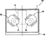
Fig. 7 is near the detailed configuration picture (cross sectional view of watching from the front portion) rotable antenna of the cooker of embodiments of the invention.
Fig. 8 is the cross sectional view of the cooker cut open of the B-B ' along Fig. 7.
Fig. 9 illustrates the example of orientation of rotable antenna of the cooker of embodiments of the invention.
Figure 10 illustrates the example of orientation of rotable antenna of the cooker of embodiments of the invention.
Figure 11 illustrates the example of orientation of rotable antenna of the cooker of embodiments of the invention.
Figure 12 illustrates the example of orientation of rotable antenna of the cooker of embodiments of the invention.
Figure 13 illustrates the example of orientation of rotable antenna of the cooker of embodiments of the invention.
Figure 14 is the cross sectional view of the cooker cut open of the D-D ' along Fig. 7.
Figure 15 is the configuration picture of the infrared sensor 10 in the cooker of embodiments of the invention.
Figure 16 is the view that the infrared temperature test point in the C-C ' cross section of Fig. 7 is shown.
Figure 17 is for explaining the cross sectional view (front view) of cooker of the infrared temperature test point of embodiments of the invention.
Figure 18 is the functional block diagram of configuration that the cooker of embodiments of the invention is shown.
Figure 19 is the flow chart that the overview of the heat treated that the cooker by embodiments of the invention carries out is shown.
Figure 20 is the flow chart of the combination function up and down that carries out of the cooker by embodiments of the invention.
Figure 21 is the flow chart of the normal function that carries out of the cooker by embodiments of the invention.
Figure 22 is the configuration picture of traditional high-frequency wave heating equipment.
Embodiment
Description of reference numerals
11: heating chamber
11a: also as the platform that holds of the lower surface of heating chamber
12: food
20: infrared ray generation device
21: argon heater
30: heating plate
40: high frequency waves generation device
41: magnetron
42: waveguide
43: rotable antenna
An aspect of cooker comprises: heating chamber, and wherein heated material is contained in also holding on platform as its lower surface; Detachable heating plate, it is removably disposed in heating chamber heated material inner and that be different from aforementioned heated material and holds thereon; Produce the high frequency waves feeding mechanism of microwave; The antenna of the microwave that radiation is produced by high frequency waves feeding mechanism; And the control device of controlling the heat treated of heated material, wherein this control device control antenna with switch for the microwave of heated material control make microwave control at least one heated material be wherein contained in also as the lower surface of heating chamber hold situation on platform and the situation holding in each of platform and heating plate that wherein at least one heated material is contained in heating chamber dissimilates, and heated shut-down operation afterwards in heated material.
By such configuration, even if heated material is only contained in also holding under the state on platform as the lower surface of heating chamber therein, or heated material is contained in also as the holding under platform and the heating plate state on the two of the lower surface of heating chamber therein, can carry out the heat treated of the state that is suitable for being wherein contained with heated material.
An aspect of cooker of the present invention also comprises heating plant, this heating plant is contained in the heated material on heating plate by being different from the thermal radiation heating of microwave heating, wherein when the first heated material is contained in also as the holding on platform and when the second heated material is contained on heating plate of the lower surface of heating chamber, control device is carried out and is controlled with switch by the heating of microwave and the thermal radiation by heating plant to heat the first heated material and the second heated material.
By this configuration, being contained in heated material on heating plate can and be heated by the thermal radiation that is different from the heating of being undertaken by microwave by the heating undertaken by microwave.
An aspect of cooker of the present invention also comprises: control device is carried out and controlled to heat second heated material by heating plant at microwave after the first heated material, the second heated material and heating plate.
By this configuration, also as the holding the first heated material and the heating plate on platform or be contained in the second heated material on heating plate and be contained in heated material on heating plate and heat by microwave before heating by radiant heat of the lower surface of heating chamber simultaneously, so that the time of comparing total time during by independent heating can shorten with the second heated material with the first heated material.
An aspect of cooker of the present invention also comprises: heating plant comprises optics heater, and control device is carried out control so that heat the second heated material to be heated by optics heater.
By this configuration, being contained in heated material on heating plate can be more fast and heat equably and become brown.
An aspect of cooker of the present invention also comprises: optics heater is the heater that can see through steam.
By this configuration, when transmitting light by steam (especially, while infrared light) being directly radiated on the surface of heated material, the surface that is contained in the heated material on heating plate can be crisp by fine finishining, and it only depends on some steam in heating chamber.
An aspect of cooker of the present invention also comprises operating unit, this operating unit choose at least one heated material be wherein contained in also as the lower surface of heating chamber hold normal function on platform and wherein at least one heated material be contained in be also used as heating chamber lower surface hold one of the combination function up and down in each of platform and heating plate, wherein control device control antenna is controlled for the microwave of heated material with switch, so that controlling, the information microwave that the operating unit of the position based on holding from appointment heated material receives dissimilates.
By this configuration, even if heated material is only contained in also holding under the state on platform as the lower surface of heating chamber therein, or wherein heated material is contained in also as the holding under platform and the heating plate state on the two of heating chamber lower surface, can carry out the heat treated of the state that is suitable for being wherein contained with heated material.Further, when cooker is configured to so that when combining up and down menu and specifying the identifying information of heated material type (menu) to carry out by input, the complicated input operation that user can combine up and down from following menu frees.
An aspect of cooker of the present invention also comprises: control device is controlled the orientation of the part of the antenna with high radiation directivity about being contained in first heated material holding platform of the lower surface that is also used as heating chamber with the information that is contained in the second heated material on heating plate based on what receive from operating unit, and completes shut-down operation afterwards in the heating of the first and second heated material.
By this configuration, even if heated material is contained in also holding under the state on platform as the lower surface of heating chamber therein, the temperature of heating plate also can effectively raise by microwave, and the heated material being contained on heating plate also can effectively heat by microwave.This allows heated material to be therein contained in also under the state on platform and heating plate, to start heat treated as holding of the lower surface of heating chamber, and the novel cooking methods of heating is so that heat in a processing in the space up and down being separated by heating plate up and down, and previous cooking methods is really not so.
An aspect of cooker of the present invention also comprises: control device is controlled the orientation of a part of the antenna with high radiation directivity so that microwave is to the first heated material when the heat treated of being undertaken by microwave is carried out in the first heated material, and microwave is treated the second heated material or heating plate when heat treated is carried out in the second heated material.
By this configuration, there is therein the direction that a part of rotable antenna of high radiation directivity faces and there is no heated material.Correspondingly, from the microwave of rotable antenna radiation, can arrive at heating plate with minimal attenuation, thus the temperature of rising heating plate, and with minimal attenuation heat the heated material being contained on heating plate.
An aspect of cooker of the present invention also comprises: control device control the antenna with high radiation directivity a part orientation so that when microwave during to the second heated material microwave to the peripheral part of heating plate.
By this configuration, there is therein the direction that a part of rotable antenna of high radiation directivity faces and there is no heated material.Correspondingly, from the microwave of rotable antenna radiation, can see through the peripheral part of heating plate, thus with minimal attenuation heat the heated material being contained on heating plate.
An aspect of cooker of the present invention also comprises: heating plate comprises high frequency waves absorber.
By this configuration, thereby high frequency waves absorber absorbs microwave, there is high temperature, and the heated material being contained on heating plate can heat from being also used as the platform that holds of the lower surface of heating chamber.
An aspect of cooker of the present invention also comprises steam providing apparatus, and this steam providing apparatus is by Steam Heating heated material, and wherein control device controls by steam providing apparatus, to heat the first heated material or the second heated material.
By this configuration, the surface of object to be heated can be prevented from burning and promote the temperature of heated material inside to raise simultaneously.In addition, because suitable humidity is applied to described surface, the surface of heated material is wrapped up by steam, and the moisture of interior of articles is difficult to flee from.As a result, can carry out wherein surface be baked into crisp inside be the culinary art of succulence.
This and after, embodiments of the invention are described with reference to the accompanying drawings.In addition the present invention the embodiment that will describe below being limited to.
The example of the outward appearance of the cooker that first, embodiment of the present invention will be described.Fig. 1 illustrates the configuration example when watching the cooker of embodiments of the invention from front surface (being wherein provided for the visually surface of the transparency window 70 of cognitive heating chamber inside).For the transparency window 70 of cognitive heating chamber 11 inside visually and the front surface that guidance panel 23 is arranged on cooker 100.Guidance panel 23 is provided with indication and starts the beginning switch 26 of heating, the cancellation switch 24 that indication heating finishes, indication use normal menu still to combine up and down menu for the switch 25 of the cooking methods that heats, display unit 27 with for selecting pre-prepd cooking process or carrying out manual dial 59.Like this, guidance panel 23 is arranged on the position that is easy to cognitive heating chamber 11 inside visually so that switch or dial can be when the checking inside of heating chamber 11 and the displaying contents of display unit 27 easy operating.
The example of the internal structure of the cooker that then, embodiment of the present invention will be described.Fig. 2 illustrates when the cooker of the embodiments of the invention cross sectional view when from left to right (towards the left and right directions of the previous section of cooker) cut open, Fig. 3 illustrates top board when the top surface of the cooker of embodiments of the invention by the cross sectional view when top surface direction is cut open, Fig. 4 illustrates wherein vapor phase for the light absorbing ratio of light wavelength, cross sectional view when Fig. 5 illustrates cooker when embodiments of the invention (direction from the front part of cooker towards the speed side of heating chamber) is broken away by from front to back.
As shown in Figures 2 and 3, the cooker 100 of embodiments of the invention comprise heating chamber 11, produce be easy to the ultrared infrared ray generation device 20 of transmission by steam, by lock part 17 support using separate vertically heating chamber heating plate, from the also food as heated material 12a as the lower surface of heating chamber 11, hold the high frequency waves generation device 40 that holds platform 11a below supply high frequency waves thereon and the steam generation device 60 that produces steam heating chamber 11.In addition, in the present embodiment, although steam generation device 60 is arranged in heating chamber 11, the steam producing outside heating chamber 11 also can be fed in heating chamber 11.
Because steam is without interruption and cycle through heating chamber by steam generation device 60, the inevitable vanishing of vapour density in the region of contact heated material 12a, and the surface of heated material 12a can prevent from excessively burning.In addition, because steam cycles through upper space (the structure realization that cycles through heating plate 30 of steam in the space of being separated by heating plate 30 equally, and the structure of heating plate 30 will be explained hereinafter), the temperature that is contained in the heated material 12b inside on heating plate 30 raises and is promoted so that heated material can prevent from excessively burning, and can partly not leave therebetween raw part.In addition, because suitable humidity is applied to surface, the surface of heated material 12b is wrapped up by steam, and the moisture of object 12b inside is difficult to escape.As a result, can carry out wherein surface is baked and thinks the crisp and culinary art of inner succulence.
In addition, as shown in Figure 5, communicating passage 14, circulating fan 15 and heater 16 are arranged on after the demarcation strip 11c on the degree of depth side of heating chamber 11, air in heating chamber 11 is drawn by circulating fan 15 and is heated (arrow that points to circulating fan 15 from heating chamber 11 in Fig. 5 shows flowing of air) by heater 16, from being arranged on the air of the tap heating demarcation strip 11c, can be sent to (arrow that points to heating chamber 11 from heater 16 in Fig. 5 shows flowing of air) in heating chamber 11.
In addition, as shown in Fig. 2 and 5, the top of heating chamber 11 is provided with a plurality of tubular heaters 21 (optics heater) (as shown in Figure 3, three are set up altogether, be included in argon heater 21a in the middle of top surface 11b and at the Milacron heater 21b of former and later two sides of argon heater 21a), it produces infrared rays as infrared ray generation device 20.Each tubular heater 21 and magnetron 41 are controlled by control unit, tubular heater 21 radiation have the infrared ray being difficult to by the wavelength of vapor absorption, and transmission is by being present in the steam in heating chamber 11, thereby heated material 12b (being heated material 12a when there is no heating plate 30) is exposed to infrared ray, thereby carries out culinary art.In addition,, when argon heater 21a and Milacron heater 21b are called by unified title, they will be called tubular heater 21.
Produce the tubular heater 21 of a plurality of wavelength, as shown in Figure 4, be configured to produce peak wavelength and be more than or equal to 1.5 μ m and be less than 1.7 μ m, be more than or equal to 2.0 μ m and be less than 2.3 μ m, be more than or equal to 3.4 μ m and be less than any one wavelength in 4.5 μ m, it is the wavelength in the region that vapor absorption ratio is low.
Thereby, the peak wavelength with the wavelength in the region that vapor absorption ratio is low is radiated heating chamber 11 from three tubular heaters 21 at the infrared ray that is more than or equal to 1.5 μ m and be less than 1.7 μ m, be more than or equal to 2.0 μ m and be less than 2.3 μ m, be more than or equal to 3.4 μ m and be less than any one wavelength in 4.5 μ m, and infrared ray is not absorbed but transmits by steam and usings radiation and the heating food as heated material 12a and 12b in steam.
As a result, the heated material 12b (12a) being contained on heating chamber 11 can directly and more fast and equably heat.In addition, when the direct radiation of infrared ray is on the surface of heated material 12b (12a), the surface of heated material 12b (12a) can be finish-machined to crisp, and becomes more rapidly brown.And, because vapor recycle without interruption, the not vanishing of vapour density in the region of contact heated material 12a or 12b, the surface of heated material 12a or 12b can prevent from excessively burning and promote the temperature of interior of articles to raise simultaneously.In addition,, because heated material 12b (12a) is wrapped up by steam, so object 12b (12a) culinary art that wherein inner moisture is difficult to escape, body surface is baked as crisp inner for succulence.
As shown in Figure 5, because tubular heater 21 is arranged in the top surface 11b of heating chamber 11, argon heater 21a is arranged on the centre of top surface 11b, and Milacron heater 21b is arranged on the both sides, front and back of argon heater 21a, and the infrared ray with the above-mentioned wavelength of expectation is produced.The heart yearn of argon heater 21a is tungsten filament, and argon gas is by transparent pipe fitting 22 sealings.Argon heater 21a has operation start than the fast feature of Milacron heater 21b.
Although used traditionally Milacron heater 21b, because its wavelength is longer than argon heater 21a, and startup is faster than mica heater, and heater is adapted so that heated material 12a and 12b become brown.In addition, there is the feature that cost is low.
At this, when Milacron heater 21b is loaded on microwave oven, there is Milacron heater 21b and absorb microwave and produce heat and the possibility of the glass material fusing just used.Like this, expectation adopts the Milacron heater 21b that has relatively low dielectric constant and be difficult to absorb the white conduit of microwave.
In this external heating chamber 11, as shown in Fig. 2 and 5, lock part 17 is arranged in opposite face in heating chamber 11 right rising wall 11d and 11d, above heating plate 30 supports vertically separate heating chamber 11 by lock part 17 and heated material 12b can be contained in.In addition, the lower space of separating by heating plate 30 can be called the first space, and upper space can be called second space.
As shown in the configuration picture of the heating plate in the cooker of the embodiments of the invention at Fig. 6, heating plate 30 has the resin-handle 33 on the side, two of left and right that is arranged on the heating plate 30 generally with rectangular plate shape, and can at fore-and-aft direction, enter or exit along the lock part 17 of heating chamber 11.In addition, the peripheral part of heating plate 30 is provided with intercommunicating pore 31, and this intercommunicating pore is vertically communicated with heating chamber 11.Thereby steam produces at the lower part of the heating chamber 11 of being separated by heating plate, and the steam producing directs into upper part by the intercommunicating pore 31 being arranged on the peripheral part of heating plate 30, thereby heating is contained in the heated material 12b on heating plate 30.The lower space that Fig. 5 illustrates from being separated by heating plate 30 is pointed to the arrow of the upper space of being separated by heating plate 30 by the peripheral part of heating plate 30.This arrow shows to point to the flowing of steam of upper space.
In addition, some microwave that is radiated the first space of heating chamber 11 passes the periphery of heating plate 30, and propagates into second space.Space on heating plate 30 the resin-handle 33 except contact lock part 17 does not contact the wall of heating chamber 11, and microwave is easy to be sent to second space from these positions.In addition the intercommunicating pore 31 being arranged in heating plate 30, also promotes microwave to be sent to second space from the first space.As a result, be contained in heated material 12b on heating plate 30 by being sent to the microwave heating of second space.Particularly, as shown in Figure 5, when micro-wave line of propagation of rotable antenna with high radiation directivity is during in the face of the peripheral part of heating plate 30, from the microwave of rotable antenna 43 radiation, in its decay, be restricted to and minimum state, be sent to equally second space.As a result, the heated material 12b being contained on heating plate 30 can be heated effectively.
In addition, for example, be desirably in also the heating element 32 that radio wave absorbing is set on platform that holds as the lower surface of heating plate 30, ferrite rubber for example, it absorbs the high frequency that produced by high frequency waves generation device 40 to produce heat.Thereby the heated material 12b being contained on heating plate 30 is heated from below, so that heated material 12b can cook from upper and lower two surfaces.In addition, the lower surface of the heating plate 30 of the heating element 32 of contact radio wave absorbing is not sprayed, so that thermal conductivity can improve and cooking time can shorten.And, if there is micro-wave line of propagation of the rotable antenna 43 of high radiation directivity, face heating plate 30, the temperature of heating plate 30 can effectively raise.
Then, will the concrete configuration of rotable antenna and the method for controlling rotable antenna be described.Fig. 7 is near the detailed configuration picture (cross sectional view of watching from the front portion) rotable antenna in the cooker of embodiments of the invention, and Fig. 8 is the cross sectional view of the cooker cut open of the B-B ' along Fig. 7.
As shown in Figure 7, cooker 100 comprises: waveguide 42, and it transmits from the microwave of magnetron 41 radiation as typical microwave generator; Heating chamber 11, it is connected to the top of waveguide 42 and has the shape that width dimensions (about 410 millimeters) is wherein greater than depth dimensions (about 315 millimeters); Hold platform 11a, it is fixed in heating chamber 11 for holding as the food (not shown) of typical heated material and having the attribute that microwave can be easy to pass therein, because hold platform, is that for example pottery or glass are made by low-loss dielectric material; Antenna space 37, it is formed on holding below platform 11a in heating chamber 11; Two rotable antennas 38 and 39, it is attached to about the position of the Width symmetry of the heating chamber 11 from waveguide 42 to antenna space 37 so that by the microwave waveguide 42 in heating chamber 11; Motor 61 and 62, it is as the typical drive unit that can drive rotationally rotable antenna 38 and 39; Control unit 160 (as shown in figure 17, after will be described), it controls motor 61 and 62 to control the orientations of rotable antenna 38 and 39; Optical interruption device 36, it forms initial point testing agency, and the rotation initial point of every rotable antenna 38 and 39 detects in this mechanism; And infrared sensor 10, it is temperature distributing detecting device, this device detects the Temperature Distribution in heating chamber 11.
In addition, rotable antenna 38 and 39 comprises: coupling unit 45 and 46, this coupling unit is through the coupling aperture with about 30 mm dias 43 and 44 of circular, this coupling aperture is arranged on waveguide 42 and also as the heating chamber of the lower surface of heating chamber, holds on the border surface between platform, and this coupling unit is made by the conductive material with the substantial cylindrical of about 18 mm dias; And radiant section 47 and 48, it is electrically connected to and is integrated into the upper end of coupling unit 45 and 46 by stuff up a crack, welding etc., and it is made than the conductive material in wider in the vertical direction region by having in the horizontal direction.
In addition the axle 49 and 50 that, rotable antenna 38 and 39 is configured to be coupled to motor 61 and 62 is so that coupling aperture 43 He44 centers become the center of rotating drive.Because radiant section 47 and 48 does not have constant shape in its rotation direction, so radiant section is configured to have radiation directivity.
Radiant section 47 and 48 is of similar shape, and radiant section upper surface 51 and 52 has the roughly R of quadrangle form.In four sides, there are radiant section sweep 53 and 54 in the face of two sides, this sweep is also crooked as holding on platform of the lower surface of heating chamber, thus the outside that is radiated these two sides of restriction microwave.Also the distance holding between platform and radiant section upper surface 51 and 52 that is used as the lower surface of heating chamber is set to about 10 millimeters, and radiant section sweep 53 and 54 drops to the position lower than about 5 millimeters of upper surface.
Other two sides have from coupling unit 45 and the 46 varying level length to end, and to form length apart from the center of coupling unit be the end 55 and 56 and be the end 57 and 58 of about 55 millimeters apart from the length at the center of coupling unit of about 75 millimeters.In addition, described end the size of Width be set to 80 millimeters or more than.In this configuration, rotable antenna 38 and 39 can be the direction of the end 57 from coupling unit 45 and 46 and 58 Enhanced Radiation Reduced Blast directivity.
In this configuration, when general food is heated by homogeneous, do not need to be especially similar to traditional microwave oven and equally food is contained in to memory location, and rotable antenna 38 and 39 can be similar to the same constant speed rotary of traditional rotable antenna.On the other hand, when forcing when hot, for example, when being heated near heating chamber 11 center, as shown in the example of the orientation of the rotable antenna of the cooker of the embodiments of the invention of Fig. 9, the end 57 and 58 that control unit 160 is controlled rotable antenna 38 and 39 is called to face the predetermined direction that is roughly heating chamber 11 center and is roughly the center of heating chamber at depth direction at Width.
When the end 57 of rotable antenna 38 and 39 and 58 is in the face of heating chamber 11 is at the approximate centre of Width and heating chamber during in depth direction approximate centre, the radiation directivity in 57 and 58 direction is high endways.Like this, microwave can be especially from the direction radiation of end 57 and 58, and the food that is positioned at this direction can be forced heat.
In addition, when being heated near the left side of heating chamber II, as shown in the example of the orientation of the rotable antenna of the cooker of the embodiments of the invention of Figure 10, control unit 160 is controlled the end 57 and 58 of rotable antenna 38 and 39 to face left side (left side when heating chamber 11 is watched from door 64).
Similarly, while being heated near the right side in heating chamber 11, as shown in the example of the orientation of the rotable antenna of the cooker of the embodiments of the invention of Figure 11, control unit 160 is controlled so that the end 57 of rotable antenna 38 and 39 and 58 is faced right side (right side when heating chamber 11 is watched from door 64).
In addition, while being heated near before heating chamber 11Zhong center, as shown in the example of the orientation of the rotable antenna of the cooker of the embodiments of the invention of Figure 12, control unit 160 control rotable antennas 38 and 39 end 57 and 58 so that in the face of heating chamber 11 at the approximate centre of Width and heating chamber in depth direction roughly anterior (near the front portion at heating chamber 11Zhong center).
In addition, while being heated near after heating chamber 11Zhong center, as shown in the example of the orientation of the rotable antenna of the cooker of the embodiments of the invention of Figure 13, control unit control rotable antenna 38 and end 57 and 58 with in the face of heating chamber 11 at Width approximate centre and heating chamber at depth direction roughly rear portion (after heating chamber 11 center near).
As mentioned above, the cooker 100 of the present embodiment is according to the orientation that is intended to carry out the Position Control rotable antenna of localized heating.In order to make rotable antenna 38 and 39 in the face of predetermined direction, utilize stepping motor as motor 61 and 62, or can consider for example to detect reference position to control the even device to the electricity time in constant revolution motor.
In the cooker of the present embodiment, stepping motor is as motor 61 and 62, and initial point testing agency is separately positioned in the axle 49 and 50 of each motor.Figure 14 illustrates the cross sectional view of the cooker of cutting open along the D-D ' of Fig. 7.Initial point testing agency, as shown in figure 14, by thering are disk 36a and optical interruption device 36 compositions as the axle of central shaft.Disk 36a is provided with rectangle slot 36b.
By this configuration, when the light path of slot 36b by optical interruption device 36, do not have anything to stop light path.Like this, the time of passing through of slot can be detected.Correspondingly, the initial point of rotable antenna can be detected by the optical interruption device 36 that is attached to each motor by slot 36b being set to the position of the initial point of rotable antenna 38 and 39.
In addition, control unit has aerial angle memory cell, and this memory cell is in the pre-stored rotable antenna 38 of initial point based on being detected by initial point testing agency and 39 angle (stop position) when having the rotable antenna 38 of high directivity and a part of 39 and be gathered in localized heating position.When the operation of rotable antenna 38 and 39 is controlled to carry out localized heating, the information of reference antenna angle memory cell.
Then, with reference to the configuration picture of the infrared sensor 10 in the cooker of the embodiments of the invention shown in Figure 15, the temperature-detecting device that the cooker of the present embodiment has is described.Temperature-detecting device comprises: a plurality of Infrared Detectorss 103 that are arranged on substrate 109; The housing 108 that holds whole substrate 109; And stepping motor 101, this motor is at the direction mobile shell 108 perpendicular to 103 orientations of Infrared Detectors.
By this configuration, along with stepping motor 101 carries out rotational motion, the vertical direction that housing 108 can be arranged at infrared detector 103 moves.
Figure 16 is the view that the infrared temperature test point in the C-C ' cross section of Fig. 7 is shown, and Figure 17 is for explaining the cross sectional view (front view) of cooker of the infrared temperature test point of embodiments of the invention.As shown in figure 17, when the control based on control unit 160 of the stepping motor 101 of temperature-detecting device rotates backward motion, the cooker 100 of the present embodiment can detect the Temperature Distribution in the nearly all region in heating chamber 11.
Particularly, the Temperature Detector 103 (for example, infrared sensor) that is arranged on the arrangement on temperature-detecting device for example detects the Temperature Distribution in A1 to the A4 region in Figure 16.Then,, when stepping motor 101 carries out rotational motion and housing 108 while moving, Temperature Detector 103 detects the Temperature Distribution in B1 to B4 regions.Then,, when stepping motor 101 carries out rotational motion and housing 108 while moving, Temperature Detector 103 detects the Temperature Distribution in C1 to C4 regions, similarly, detects the Temperature Distribution in D1 to D4 region.
In addition, when stepping motor 101 rotates counterclockwise after aforesaid operations, Temperature Distribution is with from D1 to D4, the sequence detection of C1 to C4, B1 to B4 and A1 to A4.Temperature distributing detecting device can detect the whole Temperature Distribution in heating chamber 11 by repeating aforesaid operations.
A series of processing in the heat-treatment process of passing through microwave of subsequently, the cooker of describing by embodiments of the invention being carried out.Figure 18 is the functional block diagram of configuration that the cooker of embodiments of the invention is shown.
The flow process of the processing that the cooker of the flow chart description of the summary of the heat treated of then, carrying out with reference to the cooker that the embodiments of the invention by Figure 19 are shown by embodiments of the invention carries out.When control unit 160 receptions indicate whether the operation (step S1) that basis is heated by the combination function up and down of switch 25 or any processing of normal function of guidance panel 23, control unit is carried out upper and lower combination function (step S2) or normal function (step S3) according to described operation.The flow process of the combination function up and down first, the cooker of describing by embodiments of the invention being carried out.The flow chart of the combination function up and down of the cooker by embodiments of the invention is illustrated in Figure 20.
First, control unit receives the operation that is used for combining up and down menu culinary art by guidance panel, and operation, the indication of noticing especially the state of heated material start the operation (step 201) of heat treated for operation and the indication of the condition of heat treated.The operation of noticing the state of heated material comprises the operation of the type, quantity, shape etc. of inputting heated material.Although can comprising, this input is wherein used to specify the quantity of heated material, the configuration of size and shape, and the numerical value of input measurement, but, preferably, follow the identifier of a certain formula of describing in the formula book of cooker to specify by the dial of guidance panel.In this formula book, for cooking quantity, size, the shape of required raw material, be identified for each formula.Like this, control unit can be indicated the operation of identifier of formula and the state of cognitive heated material by reception.In addition, the operation of the state of the heated material of notice embodiments of the invention is not requisite, and can comprise the wherein quantity of heated material and the configuration that temperature is measured by each transducer (not shown) being arranged in heating chamber, and the numerical value of measuring is as input value.
In addition, the condition for heat treated mainly comprises the position that heated material is placed and the method that heats heated material in each position.The position of particularly, placing heated material be indication 1-only also as the lower surface of heating chamber hold platform, 2-only heating plate and 3-also as the condition that holds platform and heating plate of the lower surface of heating chamber.
In addition in the method for each position heating heated material, be that indication heating is contained in also as the heated material on the repetition platform of the lower surface of heating chamber and is contained in the condition (by high-frequency heating, heat, heated, pass through Steam Heating, the cooking temp of each heating means, the heating time of each heating means etc. by radiant heat by hot blast) of the method for the heated material on heating plate.Although these conditions can be inputted by user by guidance panel,, preferably, specify order for each heating means of the formula of each identifier, heating-up temperature, heating time etc. to show that by reception the operation of the identifier of this formula is referenced.
In an embodiment of the present invention, by describe heated material be wherein placed on 3-also as the lower surface of heating chamber hold with heating plate on situation, particularly, need to be placed on by the heated material of microwave heating also as the holding on platform of the lower surface of heating chamber, the heated material that need to heat by radiant heat is contained on heating plate.Another heating means are identical with the method that tradition is known, and its description will be omitted.
Control unit based on by notice the heated material receiving from guidance panel state operation detection to the state (can detect by each transducer being arranged on heating chamber, it depends on concrete condition) of heated material specify and be intended to by microwave heating and be contained in also the useful load (step 202) that holds the heated material on platform as the lower surface of heating chamber.Particularly, control unit is stored the form that the type, quantity, shape of heated material is wherein associated with the load capacity of the heated material with described type, quantity, shape in ROM, and specifies the corresponding useful load of state that receive or that detected by each transducer from guidance panel based on this form.In addition, control unit can indicate the operation of the identifier of describing in formula or operating unit to notice the state of heated material by reception.Even in this case, similarly, the form that the useful load of the heated material that the identifier that control unit storage is wherein described in each formula or operating unit is required with the formula in ROM is associated, and specify the useful load corresponding to the identifier of the formula having received from guidance panel with reference to this form.
When control unit is specified the useful load of heated material, the size of useful load is determined (step 203), and wherein rotable antenna 38 and 39 end 57 and 58 directions that should face are determined, and rotable antenna 38 and 39 is in this directions rotation.The centre that control unit holds the heating chamber at place from heated material disperses end 57 and 58 directions that should face of rotable antenna 38 wherein and 39, and when being contained in the larger (step 204 of the useful load that holds the heated material on platform of the lower surface that is also used as heating chamber, Y) time, this direction is focused to (step 205) on heating plate, when the useful load of heated material hour (step 204 more, N), assemble the end 57 of rotable antenna 38 and 39 and 58 directions that should face in heating chamber (step 206) in the heart.
In addition,, in the process by microwave heating, steam can be contained in also holding the heated material platform and being contained in the heated material on heating plate as the lower surface of heating chamber to heat together from steam feeding unit 60 supply.Further, the dielectric constant that the steam supply of arrival heating chamber can be adjusted in heating chamber distributes.As a result, can suppress the non-uniform heat flux for heated material.
By this, process, if be contained in also as the useful load that holds the first heated material on platform 11a of the lower surface of heating chamber greatly, there is the rotable antenna 38 of high radiation directivity and 39 part and do not rotate and face heated material.But radiation directivity is not that the part of so high rotable antenna 38 and 39 is rotated and faced heated material, and useful load is large.Therefore, from the microwave of these partial radiations, can effectively be absorbed fully to heat heated material.On the other hand, any object to be heated does not exist and wherein has in the rotable antenna 38 of high radiation directivity and direction that 39 part is faced.Correspondingly, from the microwave of rotable antenna 38 and 39 radiation can with minimal attenuation arrive at heating plate 30, thereby the temperature of rising heating plate, and pass through the peripheral part of heating plate 30 with minimum decay, thus heating is contained in the heated material 12b on heating plate 30.
Control unit supplies power to high frequency waves generation unit 40 after rotable antenna 38 and 39 rotations, thereby starts microwave radiation (step 207).Thereafter, the microwave that rotable antenna 38 and 39 by above carries out continues until first scheduled time in the combination of certain the first and second heated material by control unit appointment (this depends in the combination of the first and second heated material for the type of the first and second heated material of its every kind combination appointment, quantity, shape etc. pre-stored) (step 208, Y).Thereby the first heated material is actively heated, heating plate 30 and the second heated material on heating plate are preheated.
(step 208 when control unit determines that first scheduled time reached, Y), microwave by rotary antenna 38 and 39 stops, and control unit supplies power to radiant heat feeding unit 20 to start by photothermal heating, to heat the heated material (step 209) being contained on heating plate 30.Thereafter, when the scheduled time has pass by and predetermined second scheduled time of determining reaches that (this depends in the combination of the first and second heated material for the type of the first and second heated material of its every kind combination appointment, quantity, shape etc. pre-stored equally, and when the heating of the first heated material completes) (step 210, Y), by photothermal heating, stop (step 212).
Like this, in this cooker, even if be contained in therein under the situation that the useful load that holds the first heated material on platform 11a of the lower surface that is also used as heating chamber is large, when starting by photothermal heating, the temperature of heating plate 30 is compared lower a little with the situation that wherein useful load is little, but fully raise, and be contained in the irradiation preheating that heated material on heating plate 30 is passed microwave equally.Therefore, the heating time when two objects heat simultaneously with when the first heated material, compare and can shorten the total heating time during with the second heated material independent heating.
In addition, even if be contained in therein in the situation that the useful load that holds the heated material on platform of the lower surface that is also used as heating chamber is little, can say, when starting by photothermal heating, heating plate 30 and heated material wherein are only positioned at situation on heating plate and compare and fully heated, and the rising of the temperature of the heating by photothermal heated material and the heating plate by microwave starts as traditional simultaneously, when time that two objects heat simultaneously with the first heated material the total heating time during with the second heated material independent heating compare and can shorten.
Control unit continues by photothermal one scheduled time of heating (step 211) after the microwave by rotable antenna 38 and 39 stops.In addition, this scheduled time according in the combination of the first and second heated material in appointment for time when the heating of the second heated material completes by pre-stored conduct equally such as the type of the first and second heated material of the appointment of its every kind combination, quantity, shape, and depend on heating time when operation with reference to the identifier of filling a prescription when indication has been received and designated.But, before can starting in the culinary art by cooker heating time, by user, by guidance panel, input heating time and specify.
In addition,, in heating process, steam can be contained in also holding the heated material platform and being contained in the heated material on heating plate as heating chamber lower surface to heat together from 60 supplies of steam feeding unit.Thereby heated material can heat by being applied to the moisture of material to be heated surface.And wherein baking culinary art or baking oven are cooked in the situation of carrying out in the heated material being contained on heating plate and can expect.When baking culinary art is carried out, also use Steam Heating, so that heated material inside can be succulence by fine finishining, prevent that surface from excessively being burnt simultaneously.On the other hand, when baking oven culinary art is carried out, steam is also used, so that inner culinary art can be improved, the surface of heated material can be thought by fine finishining crisp, and its inside can be succulence by fine finishining.
Then, when by a photothermal heating and continuous scheduled time, (step 211, Y), control unit stops by photothermal heating (step 212), and stops a series of heat treated.
Subsequently, will the flow process of the normal function of the cooker that passes through embodiments of the invention be described.The flow chart of the normal function of the cooker by embodiments of the invention is illustrated in Figure 21.
First, if user's operating operation panel 23 with set expectation fine finishining temperature (this and after be called " Temperature Setting ") (step 301), there is indication to start heating, for example press start button (step 302), control unit 160 starts heating, for example control high frequency waves feeding unit 40 to produce microwave, and microwave is transferred in heating chamber 11 (step 303) via waveguide 42.Now, the Temperature Distribution that infrared sensor 10 detects in the starting point heating chamber 11 of heating time, and control unit 160 testing result (step 304) that storage temperature distributes in memory (not shown).
Then, control unit 160 for example rotates rotable antenna 38 and 39 with in order to realize dispersed-heated (step 305) with constant speed.Dispersed-heated is for example by changing the stop position of two rotable antennas 38 and 39 and realizing by changing randomly the stop position of rotable antenna 38 and 39, and described antenna can stop at any time precalculated position to carry out localized heating by rotating continuously rotable antenna 38 and 39 in microwave vibrations process.
Then, infrared sensor 10 again detects the Temperature Distribution (step 306) in heating chamber 11 in section sometime after passing by.
Then, control unit 160 determines that the temperature rate of rise calculating reaches predetermined value or above selecting as food point (step 307).The initial temperature of control unit 160 storage heated material distributes, and calculates heated material time per unit temperature rate of rise, and determines that the temperature rate of rise calculating reaches predetermined value or above selecting is food point.This determine temperature detected place be whether also as heated material or as the food of heated material, hold place lower surface hold platform.Namely, although this by the initial temperature of freezing food, compare significantly lower feature and determined with also platform transmission microwave and its temperature difference that food absorption microwave and temperature be easy between the feature of rising that is difficult to raise in heating process that holds as lower surface with the also platform that holds as lower surface.
Then, control unit 160 determines whether the temperature difference of the food point determining (is for example equal to, or greater than predetermined value, 10 ℃) (step 308), if temperature difference is equal to, or greater than predetermined value, control unit is controlled rotable antenna 38 and 39 so that microwave is focused at (localized heating) (step 309) in the minimum temperature on food point.On the other hand, if the temperature contrast on food point is less than predetermined value, control unit is controlled rotable antenna 38 and 39 to realize dispersed-heated (step 310).
For example, if minimum temperature point is B2, the B3 in Figure 16, any one of C2, C3, rotable antenna 38 and 39 stops at the direction that rotable antenna 38 and 39 wherein adds thermal center (-tre), namely, and in the rest position shown in Fig. 9.
If minimum temperature point is B1 or C1 in Figure 16, rotable antenna 38 and 39 stops at the direction of rotable antenna 38 wherein and 39 heating left directions, namely, and in the rest position shown in Figure 10.
If minimum temperature point is B4 or C4 in Figure 16, rotable antenna 38 and 39 stops at the direction of rotable antenna 38 wherein and 39 heating right directions, namely, and in the rest position shown in Figure 11.
If minimum temperature point is A2 or A3 in Figure 16, rotable antenna 38 and 39 stops at wherein rotable antenna 38 and the anterior direction of 39 heating, namely in the rest position shown in Figure 12.
If minimum temperature point is D2 or D3 in Figure 16, rotable antenna 38 and 39 stops at wherein rotable antenna 38 and 39 and heats the direction at rear portions, namely, and in the rest position shown in Figure 13.
Then, control unit 160 determines whether the maximum temperature in food point has reached the first detected temperatures (step 311) that corresponding temperature setting is determined.If maximum temperature does not reach the first detected temperatures, control unit again detected temperatures distributes (step 306), then repeats identical operation.Again, the first detected temperatures according to food or cooking substance thing by user the fine finishining Temperature Setting via guidance panel 23 corresponding expectations, for example, lower than the temperature of 5 ℃ of Temperature Settings.
If the maximum temperature in step 311 in food point has reached the first detected temperatures, and Temperature Setting (is for example less than predetermined temperature T0,50 ℃) (step 312), control unit 160 is controlled high frequency waves feeding unit 40 (steps 313) to finish heating (step 314).This can prevent that food from for example expecting to remain on the pablum of low fine finishining temperature or butter by superheated.
In step 312, if Temperature Setting is equal to, or greater than predetermined temperature T0, this processing proceeds to step 315, for example, if Temperature Setting (is equal to, or greater than T1,80 ℃), the second detected temperatures A, ratio A, time limit A and output A are set as constant (step 316), if Temperature Setting is less than T1, the second detected temperatures B, ratio B, time limit B and output B, are set as constant (step 317).At this, if the second detected temperatures A and B are corresponding to determined two constants of Temperature Setting of setting, for example, Temperature Setting is equal to, or greater than T1 (for example, 80 ℃), and the second detected temperatures A (for example, 60 ℃) be set, if Temperature Setting is less than T1, the second detected temperatures B (for example, 50 ℃) is set.In addition, ratio A and B are two constants determining corresponding to the Temperature Setting of setting, if Temperature Setting is equal to, or greater than T1, ratio A (for example, 60%) is set, if Temperature Setting is less than T1, ratio B (for example, 50%) is set.
At this, the second detected temperatures A is set as the value larger than detected temperatures B, and ratio A is set as the value larger than ratio B.Thereby, if the Temperature Setting of setting is high, heats until become the ratio of the food point of higher temperature and become larger ratio.As a result, can lengthen heating time.Food is for example difficult to the temperature of the curry powder fricassee that warms up and can is set and fully be raise by high temperature.
In addition, time limit A and B are two constants that for example the corresponding Temperature Setting of setting is determined, if Temperature Setting is equal to, or greater than T1, the time limit, A was set, if Temperature Setting is less than T1, the time limit, B was set.At this, the time limit is desirably set as the quality of heated material when heated material continues to be heated can maintained maximum duration, and this time limit is set as than realizing the value that B is higher.
In addition, output A and B are two constants that for example the corresponding Temperature Setting of setting is determined, if Temperature Setting is equal to, or greater than T1, output A is set, if Temperature Setting is less than T2, output B is set.At this, output A (for example, 600W) is set as specific output B (for example, 500W) larger value.Thereby, food be for example difficult to the temperature of the curry powder fricassee that warms up can be at short notice along with Temperature Setting increases and export and fully rising by increase.
Then the output setting (step 318) that, control unit 160 control high frequency waves feeding units 40 are thought in step 316 and 317.Then, control unit 160 starts the time limit (step 319) of setting in calculation procedure 316 and 317.
Then, control unit 160 determines whether the point that is equal to, or greater than the second detected temperatures of setting in the step 316 and 317 in food point is equal to, or greater than the estimated rate (step 320) of setting in step 316 and 317.If this point is less than estimated rate, control unit determines in step 316 and 317 whether the time limit of setting pass by (step 321), if this time limit passes by, infrared sensor 10 is detected temperatures distribute (step 322) again.
Then, control unit 160 determines whether the temperature difference in food point is equal to, or greater than predetermined value (step 323), if temperature difference is equal to, or greater than predetermined value, control unit is controlled rotable antenna 38 and 39 so that microwave is focused at the minimum temperature point upper (step 324) in food point.On the other hand, if the temperature difference in food point is less than predetermined value, control unit is controlled rotable antenna 38 and 39 to realize dispersed-heated (step 325).Then, process and again turn back to step 320, step is subsequently repeated.
On the other hand, if be equal to, or greater than the point of the second detected temperatures in food point, be equal to, or greater than the estimated rate in step 320, control unit 160 is controlled high frequency waves feeding unit 40 (steps 326) to finish heating (step 327).In addition,, if the time limit passes by step 321, high frequency waves feeding unit 40 is controlled (step 326) to finish heating (step 327).Thereby, even if calculating the function of control unit of the estimated rate of the point be equal to, or greater than the second detected temperatures in food point presents for a certain reason and not, and it is not defined as being equal to, or greater than estimated rate, can increase heating time along with the increase of setting-up time, and the temperature of food can fully raise according to Temperature Setting.
As mentioned above, in traditional cooker, when heated material be contained in also as the lower surface of heating chamber hold on platform time, the abundant temperature of rising heating plate.But, cooker according to an embodiment of the invention, though when object to be heated be contained in also as the lower surface of heating chamber hold on platform time, the temperature of heating plate also can effectively raise.In addition, as heating by microwave before heating by radiant heat by the photothermal heated material that adds thermal target and be contained on heating plate.This can realize a kind of novel cooking methods, its therein independent heated material be contained in respectively also as holding of the lower surface of heating chamber and under the state on platform and heating plate, start and complete heat treated, namely, the heating up and down that heat in a processing in the space up and down of separating by heating plate, really not so in previous cooking methods.
In addition, cooker according to an embodiment of the invention, upper and lower combination function and normal function be switch suitably.Therefore, user can suitably select upper and lower combination function and normal function by cooking methods as required.
In addition, heating plate or be contained in heated material on heating plate and heat as described above by microwave before being passed radiant heat heating being contained in heated material on heating plate, so that compare and can shorten total heating time of the time when both are heated while heating separately with the second heated material with the first heated material simultaneously.In addition, heated material is contained in respectively also as the holding on platform and heating plate of lower surface, if start the disposable execution of operation of heat treated, heated material can heat simultaneously.The burden of the setting operation of therefore, carrying out in each heated material traditionally can be alleviated.
In addition, the direction of rotable antenna according to be contained in also as the state that holds the heated material on platform of the lower surface of heating chamber for example shape, weight and quantity control so that obtain being contained in also as the microwave that holds the heated material on platform of the lower surface of heating chamber or to the peripheral part of heating plate or the microwave of heating plate switch suitably.
In addition,, if the heated material of right quantity is contained in also as the holding on platform and heating plate of the lower surface of heating chamber according to the formula book of following cooker, cooker can be carried out and be set up and down menu by the identifying information of input specified mix simply.As a result, the complicated input operation that user sets menu up and down from following frees.
Although the present invention is described with reference to specific embodiment in detail,, it will be apparent to those skilled in the art that and can carry out variously substituting and revising and do not exceed the spirit and scope of the present invention.
The application is based on the Japanese patent application No.2007-322044 submitting on December 13rd, 2007, and the content of this application is referred to herein as a reference.
Commercial Application
As mentioned above, according to cooker of the present invention, even if heated material is contained in also as the holding under the state on platform of the lower surface of heating chamber therein, the temperature of heating plate also can effectively raise by microwave, and the heated material being contained on heating plate also can be by microwave heating.In other words, can present such effect, heated material can be contained in also holding platform and heating plate the two above also heats as the lower surface of heating chamber thereon.Therefore, the present invention is useful in the relevant field of the cooker to dielectric heating heated material.
Claims (9)
1. a cooker, comprising:
Heating chamber, wherein the first heated material is contained in also holding on platform as the lower surface of this heating chamber;
Detachable heating plate, it is inner that it is removably disposed in described heating chamber, and the second heated material that is different from described the first heated material is contained on this heating plate;
High frequency waves feeding mechanism, it produces microwave;
Antenna, the microwave that its radiation produces by described high frequency waves feeding mechanism; And
Control device, it controls the heat treated of described the first and second heated material,
Wherein said control device controls that described antenna is controlled for the microwave of described the first and second heated material with switch so that be contained in also as the situation microwave in each of platform and described heating plate of holding that situation on platform and wherein said the first and second heated material are contained in respectively described heating chamber that holds of the lower surface of heating chamber and control and dissimilate at least one heated material wherein, and shut-down operation after heating completes;
Operating unit, hold normal function on platform and wherein said the first and second heated material that this operating unit selects at least one heated material to be wherein contained in also as the lower surface of heating chamber are contained in respectively also one of the combination function up and down in each of platform and heating plate that holds as the lower surface of heating chamber
Wherein said control device control that described antenna is controlled for the microwave of described the first and second heated material with switch so that microwave control the appointment based on receiving from described operating unit described the first and second heated material contained location information and dissimilate;
Wherein said control device is controlled the orientation of the part of the described antenna with high radiation directivity about being contained in first heated material holding platform of the lower surface that is also used as heating chamber with the heat treated information that is contained in the second heated material on described heating plate based on what receive from described operating unit, and completes shut-down operation afterwards in the heating of described the first and second heated material.
2. cooker as claimed in claim 1, comprising:
Heating plant, it is contained in the heated material on described heating plate by being different from the thermal radiation heating of microwave heating,
Wherein when the first heated material be contained in also as the lower surface of described heating chamber hold on platform and when the second heated material is contained on described heating plate, described control device is carried out and is controlled with switch by the heating of microwave with by the thermal radiation of heating plant, thereby heats described the first heated material and the second heated material.
3. cooker as claimed in claim 2,
Wherein, described control device is carried out and is controlled to heat second heated material by heating plant at microwave after described the first heated material, the second heated material and heating plate.
4. cooker as claimed in claim 2,
Wherein, described heating plant comprises optics heater, and
Described control device is carried out and is controlled so that described the second heated material heats by described optics heater.
5. cooker as claimed in claim 4,
Wherein, described optics heater is the heater that can see through steam.
6. cooker as claimed in claim 1,
Wherein, described control device is controlled the orientation of a described part of the described antenna with high radiation directivity so that microwave is to the first heated material when the heat treated by microwave is carried out in the first heated material, and when heat treated is carried out in the second heated material microwave to the second heated material or heating plate.
7. cooker as claimed in claim 6,
Wherein, described control device control the described antenna with high radiation directivity a described part orientation so that when microwave during to the second heated material microwave arrive the peripheral part of described heating plate.
8. cooker as claimed in claim 1,
Wherein, described heating plate comprises high frequency waves absorber.
9. cooker as claimed in claim 2, comprising:
Steam providing apparatus, it passes through Steam Heating heated material,
Wherein said control device controls by described steam providing apparatus, to heat the first heated material or the second heated material.
Applications Claiming Priority (3)
| Application Number | Priority Date | Filing Date | Title |
|---|---|---|---|
| JP322044/07 | 2007-12-13 | ||
| JP2007322044A JP4629089B2 (en) | 2007-12-13 | 2007-12-13 | Cooker |
| PCT/JP2008/003649 WO2009075090A1 (en) | 2007-12-13 | 2008-12-08 | Cooking device |
Publications (2)
| Publication Number | Publication Date |
|---|---|
| CN101897234A CN101897234A (en) | 2010-11-24 |
| CN101897234B true CN101897234B (en) | 2014-05-07 |
Family
ID=40755338
Family Applications (1)
| Application Number | Title | Priority Date | Filing Date |
|---|---|---|---|
| CN200880120818.XA Expired - Fee Related CN101897234B (en) | 2007-12-13 | 2008-12-08 | Cooking device |
Country Status (5)
| Country | Link |
|---|---|
| US (1) | US20100288756A1 (en) |
| EP (1) | EP2234456B1 (en) |
| JP (1) | JP4629089B2 (en) |
| CN (1) | CN101897234B (en) |
| WO (1) | WO2009075090A1 (en) |
Families Citing this family (10)
| Publication number | Priority date | Publication date | Assignee | Title |
|---|---|---|---|---|
| JP5131969B2 (en) * | 2007-12-19 | 2013-01-30 | パナソニック株式会社 | Cooker |
| JP5593722B2 (en) * | 2010-02-12 | 2014-09-24 | パナソニック株式会社 | Microwave heating cooker |
| JPWO2011114682A1 (en) * | 2010-03-17 | 2013-06-27 | パナソニック株式会社 | Cooker |
| US9533461B2 (en) * | 2012-04-11 | 2017-01-03 | Fuji Seiko Co., Ltd. | Bead-ring winder |
| US11153943B2 (en) * | 2014-07-10 | 2021-10-19 | Panasonic Intellectual Property Management Co., Ltd. | Microwave heating device |
| US10251223B2 (en) * | 2015-05-20 | 2019-04-02 | Illinois Tool Works Inc. | Apparatus for providing customizable heat zones in an oven |
| US10108335B2 (en) | 2015-06-05 | 2018-10-23 | Apple Inc. | Touch-based interactive learning environment |
| CN107752794B (en) * | 2017-09-27 | 2020-10-09 | 珠海格力电器股份有限公司 | Baking method and device |
| CN111124002B (en) * | 2018-10-30 | 2021-06-15 | 宁波方太厨具有限公司 | Accurate temperature control method for household appliance |
| DE102019201332A1 (en) * | 2019-02-01 | 2020-08-06 | BSH Hausgeräte GmbH | Household cooking appliance and method for operating a household cooking appliance |
Citations (2)
| Publication number | Priority date | Publication date | Assignee | Title |
|---|---|---|---|---|
| CN1430020A (en) * | 2001-12-27 | 2003-07-16 | 三洋电机株式会社 | High-frequency heating device |
| CN1455178A (en) * | 2002-04-29 | 2003-11-12 | 乐金电子(天津)电器有限公司 | Upper portion heater structure for microwave oven |
Family Cites Families (26)
| Publication number | Priority date | Publication date | Assignee | Title |
|---|---|---|---|---|
| JPS5164936U (en) * | 1974-11-18 | 1976-05-21 | ||
| US4329557A (en) * | 1979-12-07 | 1982-05-11 | General Electric Company | Microwave oven with improved energy distribution |
| FR2575640B1 (en) * | 1985-01-09 | 1989-12-22 | Jovanovic Dragomir | METHOD FOR THE COOKING OF ALL FOODS AND DEVICE FOR IMPLEMENTING SAME |
| US4596915A (en) * | 1985-05-07 | 1986-06-24 | Amana Refrigeration, Inc. | Microwave oven having resonant antenna |
| KR950014687A (en) * | 1993-11-13 | 1995-06-16 | 이헌조 | Microwave |
| US5523549A (en) * | 1994-05-25 | 1996-06-04 | Ceramic Powders, Inc. | Ferrite compositions for use in a microwave oven |
| JP2897645B2 (en) * | 1994-08-04 | 1999-05-31 | 松下電器産業株式会社 | Cooking device |
| JPH0864356A (en) * | 1994-08-19 | 1996-03-08 | Hitachi Home Tec Ltd | High frequency heating device |
| FR2725497B1 (en) * | 1994-10-11 | 1997-01-03 | Europ Pour La Fabrication D En | MICROWAVE OVEN |
| JP3603356B2 (en) * | 1994-12-28 | 2004-12-22 | 松下電器産業株式会社 | High frequency heating equipment |
| US6249710B1 (en) * | 1996-05-14 | 2001-06-19 | Microwave Science, Llc | Method and apparatus for managing the thermal activity of a microwave oven |
| SE518761C2 (en) * | 1998-10-15 | 2002-11-19 | Whirlpool Co | Microwave with grill |
| JP2001248840A (en) * | 2000-03-03 | 2001-09-14 | Mitsubishi Electric Corp | Heating cooking system |
| JP2002130684A (en) * | 2000-10-31 | 2002-05-09 | Mitsubishi Electric Corp | Heating cooking apparatus |
| JP3825644B2 (en) * | 2001-02-28 | 2006-09-27 | 三洋電機株式会社 | microwave |
| JP2003294241A (en) * | 2002-04-01 | 2003-10-15 | Matsushita Electric Ind Co Ltd | Heating cooker |
| JP2004071216A (en) | 2002-08-02 | 2004-03-04 | Sharp Corp | Microwave heating apparatus |
| JP4278502B2 (en) * | 2002-12-12 | 2009-06-17 | パナソニック株式会社 | Induction heating cooker |
| EP1458220B1 (en) * | 2003-03-12 | 2006-06-07 | Matsushita Electric Industrial Co., Ltd. | High frequency heating apparatus having a steam generating function |
| JP2005147604A (en) * | 2003-11-19 | 2005-06-09 | Matsushita Electric Ind Co Ltd | High frequency heating cooking device, and cooking method using the device |
| JP2006097988A (en) * | 2004-09-29 | 2006-04-13 | Sanyo Electric Co Ltd | Microwave oven |
| JP2006286443A (en) * | 2005-04-01 | 2006-10-19 | Matsushita Electric Ind Co Ltd | Microwave heating device |
| JP2007139245A (en) * | 2005-11-16 | 2007-06-07 | Matsushita Electric Ind Co Ltd | High frequency heating cooking apparatus |
| JP5116260B2 (en) * | 2006-06-19 | 2013-01-09 | パナソニック株式会社 | High frequency heating device |
| JP2008241062A (en) * | 2007-03-26 | 2008-10-09 | Matsushita Electric Ind Co Ltd | Heating cooker |
| JP2008281302A (en) * | 2007-05-14 | 2008-11-20 | Panasonic Corp | Heating cooker |
-
2007
- 2007-12-13 JP JP2007322044A patent/JP4629089B2/en active Active
-
2008
- 2008-12-08 US US12/747,757 patent/US20100288756A1/en not_active Abandoned
- 2008-12-08 CN CN200880120818.XA patent/CN101897234B/en not_active Expired - Fee Related
- 2008-12-08 WO PCT/JP2008/003649 patent/WO2009075090A1/en active Application Filing
- 2008-12-08 EP EP08860461.6A patent/EP2234456B1/en not_active Not-in-force
Patent Citations (2)
| Publication number | Priority date | Publication date | Assignee | Title |
|---|---|---|---|---|
| CN1430020A (en) * | 2001-12-27 | 2003-07-16 | 三洋电机株式会社 | High-frequency heating device |
| CN1455178A (en) * | 2002-04-29 | 2003-11-12 | 乐金电子(天津)电器有限公司 | Upper portion heater structure for microwave oven |
Also Published As
| Publication number | Publication date |
|---|---|
| EP2234456B1 (en) | 2016-05-04 |
| JP2009144970A (en) | 2009-07-02 |
| US20100288756A1 (en) | 2010-11-18 |
| CN101897234A (en) | 2010-11-24 |
| JP4629089B2 (en) | 2011-02-09 |
| EP2234456A4 (en) | 2013-07-24 |
| WO2009075090A1 (en) | 2009-06-18 |
| EP2234456A1 (en) | 2010-09-29 |
Similar Documents
| Publication | Publication Date | Title |
|---|---|---|
| CN101897234B (en) | Cooking device | |
| CN101903705B (en) | Cooker | |
| CN101910731B (en) | Cooking device | |
| JP5310741B2 (en) | Microwave heating cooker | |
| JP5152971B2 (en) | Cooker | |
| CN101878672A (en) | Cooking device | |
| JP2009144970A5 (en) | ||
| CN101473693A (en) | Microwave heating device | |
| JP2009129844A5 (en) | ||
| JP2010002170A (en) | Cooker | |
| US20100270292A1 (en) | Cooker | |
| US10827569B2 (en) | Crispness and browning in full flat microwave oven | |
| JP3063643B2 (en) | Heating equipment | |
| JP5593710B2 (en) | Microwave heating cooker | |
| JP4306005B2 (en) | High frequency heating device | |
| WO2022044719A1 (en) | High frequency heating cooker | |
| WO2023074551A1 (en) | Microwave heating device | |
| JP2001304582A (en) | High frequency heating device | |
| JP2013143251A (en) | Microwave heating apparatus |
Legal Events
| Date | Code | Title | Description |
|---|---|---|---|
| C06 | Publication | ||
| PB01 | Publication | ||
| C10 | Entry into substantive examination | ||
| SE01 | Entry into force of request for substantive examination | ||
| C14 | Grant of patent or utility model | ||
| GR01 | Patent grant | ||
| CF01 | Termination of patent right due to non-payment of annual fee |
Granted publication date: 20140507 Termination date: 20201208 |
|
| CF01 | Termination of patent right due to non-payment of annual fee |