CN101856255A - Be used to cut method and apparatus with fastening tissue - Google Patents
Be used to cut method and apparatus with fastening tissue Download PDFInfo
- Publication number
- CN101856255A CN101856255A CN201010159993A CN201010159993A CN101856255A CN 101856255 A CN101856255 A CN 101856255A CN 201010159993 A CN201010159993 A CN 201010159993A CN 201010159993 A CN201010159993 A CN 201010159993A CN 101856255 A CN101856255 A CN 101856255A
- Authority
- CN
- China
- Prior art keywords
- jaw
- stomach
- cutting
- end effector
- tissue
- Prior art date
- Legal status (The legal status is an assumption and is not a legal conclusion. Google has not performed a legal analysis and makes no representation as to the accuracy of the status listed.)
- Pending
Links
Images


Classifications
-
- A—HUMAN NECESSITIES
- A61—MEDICAL OR VETERINARY SCIENCE; HYGIENE
- A61B—DIAGNOSIS; SURGERY; IDENTIFICATION
- A61B17/00—Surgical instruments, devices or methods, e.g. tourniquets
- A61B17/02—Surgical instruments, devices or methods, e.g. tourniquets for holding wounds open; Tractors
- A61B17/0218—Surgical instruments, devices or methods, e.g. tourniquets for holding wounds open; Tractors for minimally invasive surgery
-
- A—HUMAN NECESSITIES
- A61—MEDICAL OR VETERINARY SCIENCE; HYGIENE
- A61B—DIAGNOSIS; SURGERY; IDENTIFICATION
- A61B17/00—Surgical instruments, devices or methods, e.g. tourniquets
- A61B17/00234—Surgical instruments, devices or methods, e.g. tourniquets for minimally invasive surgery
-
- A—HUMAN NECESSITIES
- A61—MEDICAL OR VETERINARY SCIENCE; HYGIENE
- A61B—DIAGNOSIS; SURGERY; IDENTIFICATION
- A61B17/00—Surgical instruments, devices or methods, e.g. tourniquets
- A61B17/068—Surgical staplers, e.g. containing multiple staples or clamps
- A61B17/072—Surgical staplers, e.g. containing multiple staples or clamps for applying a row of staples in a single action, e.g. the staples being applied simultaneously
- A61B17/07207—Surgical staplers, e.g. containing multiple staples or clamps for applying a row of staples in a single action, e.g. the staples being applied simultaneously the staples being applied sequentially
-
- A—HUMAN NECESSITIES
- A61—MEDICAL OR VETERINARY SCIENCE; HYGIENE
- A61B—DIAGNOSIS; SURGERY; IDENTIFICATION
- A61B17/00—Surgical instruments, devices or methods, e.g. tourniquets
- A61B17/00234—Surgical instruments, devices or methods, e.g. tourniquets for minimally invasive surgery
- A61B2017/00238—Type of minimally invasive operation
- A61B2017/00278—Transorgan operations, e.g. transgastric
-
- A—HUMAN NECESSITIES
- A61—MEDICAL OR VETERINARY SCIENCE; HYGIENE
- A61B—DIAGNOSIS; SURGERY; IDENTIFICATION
- A61B17/00—Surgical instruments, devices or methods, e.g. tourniquets
- A61B2017/00743—Type of operation; Specification of treatment sites
- A61B2017/00818—Treatment of the gastro-intestinal system
-
- A—HUMAN NECESSITIES
- A61—MEDICAL OR VETERINARY SCIENCE; HYGIENE
- A61B—DIAGNOSIS; SURGERY; IDENTIFICATION
- A61B17/00—Surgical instruments, devices or methods, e.g. tourniquets
- A61B17/068—Surgical staplers, e.g. containing multiple staples or clamps
- A61B17/072—Surgical staplers, e.g. containing multiple staples or clamps for applying a row of staples in a single action, e.g. the staples being applied simultaneously
- A61B2017/07214—Stapler heads
- A61B2017/07285—Stapler heads characterised by its cutter
-
- A—HUMAN NECESSITIES
- A61—MEDICAL OR VETERINARY SCIENCE; HYGIENE
- A61B—DIAGNOSIS; SURGERY; IDENTIFICATION
- A61B17/00—Surgical instruments, devices or methods, e.g. tourniquets
- A61B17/32—Surgical cutting instruments
- A61B2017/320052—Guides for cutting instruments
-
- A—HUMAN NECESSITIES
- A61—MEDICAL OR VETERINARY SCIENCE; HYGIENE
- A61B—DIAGNOSIS; SURGERY; IDENTIFICATION
- A61B17/00—Surgical instruments, devices or methods, e.g. tourniquets
- A61B17/34—Trocars; Puncturing needles
- A61B17/3462—Trocars; Puncturing needles with means for changing the diameter or the orientation of the entrance port of the cannula, e.g. for use with different-sized instruments, reduction ports, adapter seals
- A61B2017/3466—Trocars; Puncturing needles with means for changing the diameter or the orientation of the entrance port of the cannula, e.g. for use with different-sized instruments, reduction ports, adapter seals for simultaneous sealing of multiple instruments
-
- A—HUMAN NECESSITIES
- A61—MEDICAL OR VETERINARY SCIENCE; HYGIENE
- A61B—DIAGNOSIS; SURGERY; IDENTIFICATION
- A61B90/00—Instruments, implements or accessories specially adapted for surgery or diagnosis and not covered by any of the groups A61B1/00 - A61B50/00, e.g. for luxation treatment or for protecting wound edges
- A61B90/50—Supports for surgical instruments, e.g. articulated arms
Abstract
The invention provides the method and apparatus that is used to cut with fastening tissue.In one embodiment, surgery device can be used for crosscut stomach at least in part, but does not cut and/or be not fastened at the part tissue of the end effector of the far-end that is arranged in described device.The part of described stomach can be engaged by described end effector, and actuatable described end effector is applied to this tissue with the tissue that engages in the distal portions that cuts described end effector and/or with one or more fasteners, but does not cut the tissue that engages in the proximal part of described end effector and/or fastener is applied to this tissue.In a similar manner, described surgery device can be used for wherein expecting cutting and/or the distal portions of the fastening tissue that is engaged by described end effector and not cutting in any surgical operation of proximal part of the tissue that is engaged by described end effector.
Description
Technical field
The present invention relates to be used to cut the method and apparatus with fastening tissue, specifically, relate to the method and apparatus that is used to implement gastroplasty.
Background technology
Obesity has caused increasing concern (particularly in the U.S.), and this is because the quantity of obese people continues to increase and people recognize fat negative effect to health status more.Particularly, morbid obesity patient (body weight surpasses 100 pounds of ideal body weights or more people) has the risk of serious health problem very big.Therefore, the treatment for the obese patient receives much concern.The surgical operation that is used for the treatment of morbid obesity comprises stomach detour operation (stomach is performed the operation at interval), the operation of adjustable stomach hoop and vertical band gastroplasty and oversleeve shape stomach resecting operation (removing whole stomaches or part stomach).This class surgical operation carries out under peritoneoscope more and more.The advantage that laparoscopic surgery is generally acknowledged is rehabilitation duration after the desmopyknosis, significantly alleviates postoperative pain and wound infection and improve appearance, and this mainly is because laparoscopic surgeon can utilize the less otch of body lumen wall to carry out operation.Yet, in the operation of this class bariatrician, need a plurality of abdominal incisions usually, thus, the chance that worthless postoperative consequence (for example, outward appearance scabs) occurs increases.
Because gastroplasty does not stay any foreign body and does not need complicated intestinal bypass in patient's body, so gastroplasty more and more has been subjected to surgeon and patient's favor, use it for treatment of obesity and be used for the treatment of disease of stomach, for example cancer (will remove a part of stomach).Alternatively, cut apart the volume that can reduce stomach by stomach being carried out part, thereby between esophagus and intestinal, stay stomach " oversleeve." operation of peritoneoscope stomach plasty is usually directed to inflate to the abdominal cavity with carbon dioxide, up to the pressure that reaches about 15 millimetress of mercury (mm Hg).Pierce through abdominal wall, inserting diameter then in the abdominal cavity is the straight tubular cannula or the trocar of 5-10mm.The peritoneoscope that is connected to the operating room monitor is passed a trocar, in order to observe the wild situation of art.Laparoscopic instrument is arranged to pass two or more other trocars, handles for surgeon and surgical operation assistant.Therefore, this class laparoscopic surgery can need to be incorporated into the intravital a plurality of apparatuses of patient by a plurality of otch that may scab, and/or can cause interference between apparatus close to each other.By identical otch two or more standard cannula and laparoscopic instrument can be caused so-called " chopsticks effect " by putting into abdominal part and/or two or more apparatuses being put into abdominal part each other, it describes between the surgical hands, between surgical hands and the apparatus and the interference between the apparatus.This interference can reduce the ability that the surgeon carries out described operation greatly.In addition, in Magenstrasse and Mill stomach plastic operation (only excise a part of stomach and form the stomach oversleeve), the original position of stomach oversleeve must be distinguished, extra use instrument and surgical operation time can be needed like this.
Therefore, need the method and apparatus of excision and fastening tissue, it makes that patient's rehabilitation duration is the shortest, improves appearance, minimizing " chopsticks " effect and make that the surgical operation persistent period is the shortest.
Summary of the invention
The present invention relates in general to a kind of method and apparatus that is used to cut with fastening tissue.In one embodiment, provide a kind of surgery device, it comprises can relative to each other active first jaw and second jaw, and described first jaw and second jaw can engage the tissue between them.But described device also comprise can translation between the near-end of first jaw and second jaw and far-end cutting element.Move between the second position in the distal region that described cutting element can be cut at the tissue of organizing primary importance in the proximal region that is not cut and first jaw and second jaw of first jaw and second jaw.
Device can have many modification.For example, cutting element can along with the cutting element translation through first jaw and second jaw and between the primary importance and the second position, pivot.Cutting element can comprise the otch that is formed on wherein, and described otch can allow cutting element to pivot between the primary importance and the second position.For another example, in first jaw and second jaw at least one can comprise cam member, described cam member can along with the cutting element translation through first jaw and second jaw and cutting element from the primary importance and the second position is moved in the primary importance and the second position another.For another example, cutting element can along from the distally to the direction translation of nearside through first jaw and second jaw with cut and organize and/or cutting element can be along direction translation from nearside to the distally through first jaw and second jaw to cut and organize.For another example, proximal region can comprise the total length that extends between the near-end of first jaw and second jaw and the far-end at least about 50%.
In another embodiment, provide a kind of surgery device, the end effector that it comprises slender axles and is attached to the far-end of slender axles, described end effector can engage with tissue.Described device also be included between the near-end of end effector and the far-end can translation cutting element.Move between the second position of the distal region that described cutting element can be cut at the tissue of primary importance in the proximal region that organizing of end effector is not cut and end effector.
Device can any other number mode change.For example, described cutter sweep can far-end to the direction of near-end along the end effector translation to cut and organize.As another example, described cutter sweep can rotate between the primary importance and the second position.As another example, described device can also comprise cam member, and described cam member can move to cutting element from the primary importance and the second position in the process of end effector translation in the primary importance and the second position another at cutting element.As another example, proximal region can be included in the total length that extends between the near-end of end effector and the far-end at least about 50%.
On the other hand, provide a kind of surgical method, it comprises: surgery device is pushed in patient's the body cavity; The part of patient's stomach is bonded between first jaw and second jaw of the end effector that is in described surgery device far-end; With proximal region and the distal region translation of cutting element, make that being bonded on organizing in the proximal region is not cut the element cutting, and the tissue that is bonded in the distal region is cut the element cutting along first jaw and second jaw.
This method can have many modification.For example, in the process of first jaw and the second jaw translation, described method can comprise at cutting element: with cutting element with respect to first jaw and second jaw in the proximal region of first jaw and second jaw primary importance and the second position in the distal region of first jaw and second jaw between move.For another example, cutting element can be comprised along the near-end of first jaw and second jaw and the step of distal region translation: cutting element is moved along first jaw and second jaw on the direction from nearside to the distally.For another example, before the step that the part of first jaw of end effector and the stomach between second jaw engages, this method can comprise: the near-end basic fixed position of end effector is positioned the position contiguous at a certain distance with the His angle of stomach in the gastric antrum place of stomach and with the far-end of end effector.For another example, cutting element can be comprised along the proximal region of first jaw and second jaw and the step of distal region translation: cutting from the position of the gastric antrum of contiguous stomach to the His angle of stomach.For another example, cutting element can be comprised along the proximal region of first jaw and second jaw and the step of distal region translation: in the antetheca of stomach, form first slit and in the rear wall of stomach, form isolating second slit.For another example, the endoceliac step that surgery device is pushed the patient can comprise: surgery device is pushed be formed on the intravital abdominal part of patient and enter the hole and send or be formed on the intravital vagina of patient to and enter in the hole one.
In another embodiment, a kind of surgery device is provided, it comprises relative to each other mobilizable first jaw and second jaw, described first jaw and second jaw have proximal region and distal region, described distal region can be used in tissue that cutting engages and a plurality of fasteners is delivered to this tissue in the distal region of first jaw and second jaw, described proximal region can not engage with tissue and fastening and do not cut and organize.
Device can have many modification.For example, described device can comprise a plurality of fasteners in the distal region that is arranged on first jaw and second jaw.Described device can also comprise the storehouse in that is arranged in first jaw and second jaw, and the distal region in described storehouse comprises a plurality of fasteners within it, and described proximal region does not have fastener.In one embodiment, proximal region can comprise the total length that extends between the near-end of first jaw and second jaw and the far-end at least about 20%.Described device can also comprise the cutting element of translation continuously through described proximal region and distal region, and described cutting element cutting is bonded on the tissue in the distal region and does not cut the tissue that is bonded in the proximal region.Move between the primary importance that described cutting element can be in proximal region and the second position that is rotated into from primary importance in the distal region, wherein do not cut the tissue that engages by first jaw and second jaw, the tissue that engages by first jaw and second jaw in the cutting element cutting of the second position at the cutting element of primary importance.In certain embodiments, in first jaw and second jaw at least one can comprise cam member, and described cam member can move in the primary importance and the second position another with cutting element from the primary importance and the second position in through the process of first jaw and second jaw in the cutting element translation.
In another embodiment, provide a kind of surgery device, the end effector that it comprises slender axles and is attached to the far-end of slender axles.Described end effector can have the proximal region that a plurality of fasteners can be delivered to the distal region that is bonded on tissue wherein and no fastener that can joining tissue.Described device can also comprise cutting element, and described cutting element can be along the end effector translation, the tissue that engages by distal region with cutting, and do not cut the tissue that the proximal region by the no fastener of end effector engages.
In one embodiment, described cutting element can move between the second position in the distal region that the primary importance in organizing the proximal region that is not cut and tissue are cut.Described device can also comprise cam member, and described cam member can move to cutting element from the primary importance and the second position in the process of end effector translation in the primary importance and the second position another at cutting element.Cutting element can rotate between the primary importance and the second position in the process of end effector translation at cutting element.Cutting element can also near-end to the direction of far-end or far-end to the direction of near-end along the end effector translation to cut and organize.In another embodiment, the longitudinal length of proximal region can be greater than the longitudinal length of distal region.
In yet another aspect, provide a kind of surgical method, it comprises: surgery device is pushed in patient's the body cavity; Engage the antetheca and the rear wall of patient's stomach by the end effector on the surgery device far-end, make the flanging of stomach be located in the proximal region of end effector; And activate described surgery device, the flanging of or not stomach to form crosscut under one's belt.
This method can have many modification.For example, the step that activates surgery device can comprise: make the cutting element motion pass the proximal region of end effector and do not cut antetheca and the rear wall and the flanging of the stomach that the proximal region by end effector engages, and make the cutting element motion pass the distal region of end effector, with antetheca and the rear wall of cutting by the stomach of the distal region joint of end effector.As another example, the step that activates surgery device can comprise: a plurality of fasteners are delivered to the antetheca and the rear wall of the stomach that the distal region by end effector engages, and any fastener are not delivered to antetheca and the rear wall and the flanging of the stomach that the proximal region by end effector engages.As another example, form crosscut under one's belt and the hemmed step of not crosscut stomach can comprise: crosscut is near the His angle to stomach, the position of the gastric antrum of stomach.As another example, form transverse incision under one's belt and the hemmed step of not crosscut stomach can comprise: in antetheca, form first slit and in rear wall, form isolating second slit.As another example, the endoceliac step that surgery device is pushed the patient can comprise: surgery device is pushed be formed on the intravital abdominal part of patient and enter the hole or be formed on the intravital vagina of patient and enter in the hole one.
The present invention specifically discloses following content:
(1). a kind of surgery device comprises:
First jaw and second jaw, described first jaw and second jaw are can be relative to each other movable and can be bonded on tissue between described first jaw and second jaw; With
Cutting element, described cutting element can translation between the near-end of described first jaw and second jaw and far-end, moves between the second position in the distal region that described cutting element can be cut at the tissue of organizing primary importance in the proximal region that is not cut and described first jaw and second jaw of described first jaw and second jaw.
(2). according to (1) described device, wherein said cutting element can pivot between the described primary importance and the described second position when described cutting element translates across described first jaw and second jaw.
(3). according to (2) described device, wherein be formed with otch in described cutting element, described otch can allow described cutting element to pivot between the described primary importance and the second position.
(4). according to (1) described device, in wherein said first jaw and second jaw at least one comprises cam member, and described cam member can be when described cutting element translates across described first jaw and second jaw moves in the described primary importance and the second position another with described cutting element from the described primary importance and the second position.
(5). according to (1) described device, wherein said cutting element can be from the distally translates across described first jaw and second jaw to cut and organize to the direction of nearside.
(6). according to (1) described device, wherein said cutting element can the direction from nearside to the distally translates across described first jaw and second jaw to cut and organize.
(7). according to (1) described device, wherein said proximal region comprise the total length that extends between the near-end of described first jaw and second jaw and the far-end at least about 20%.
(8). a kind of surgery device comprises:
Slender axles;
End effector, described end effector is connected to the far-end of described slender axles, and described end effector can joining tissue; With
Cutting element, described cutting element can translation between the near-end of described end effector and far-end, moves between the second position in the distal region that described cutting element can be cut at the tissue of primary importance in the proximal region that organizing of described end effector is not cut and described end effector.
(9). according to (8) described device, wherein said cutting element can be from the distally to the direction of nearside along described end effector translation to cut and organize.
(10). according to (8) described device, wherein said cutting element can rotate between the described primary importance and the second position.
(11). according to (8) described device, also comprise cam member, described cam member can be at described cutting element along in the process of described end effector translation described cutting element from the described primary importance and the second position being moved in the described primary importance and the second position another.
(12). according to (8) described device, wherein said proximal region be included in the total length that extends between the near-end of described end effector and the far-end at least about 20%.
(13). a kind of surgical method comprises:
Surgery device is advanced in patient's the body cavity;
The part of described patient's stomach is bonded between first jaw and second jaw of the end effector that is in described surgery device far-end;
With proximal region and the distal region translation of cutting element along described first jaw and second jaw, make that being bonded on not organizing of described proximal region is cut by described cutting element, and make the tissue that is bonded in the described distal region be cut by described cutting element.
(14). according to (13) described method, also comprise: at described cutting element along in the process of described first jaw and the second jaw translation, with described cutting element with respect to described first jaw and second jaw in the described proximal region of described first jaw and second jaw primary importance and the second position in the described distal region of described first jaw and second jaw between move.
(15). according to (13) described method, wherein proximal region and the distal region translation of described cutting element along described first jaw and second jaw comprised: described cutting element is moved along described first jaw and second jaw with the direction from nearside to the distally.
(16). according to (13) described method, also comprise: before a part that makes described stomach is bonded between first jaw of described end effector and second jaw, the near-end basic fixed position of described end effector is positioned the position contiguous at a certain distance with the His angle of stomach in the gastric antrum place of described stomach and with the far-end of described end effector.
(17). according to (13) described method, wherein proximal region and the distal region translation of described cutting element along described first jaw and second jaw comprised: cut the His angle of described stomach to described stomach from the position of the gastric antrum of contiguous described stomach.
(18). according to (13) described method, wherein proximal region and the distal region translation of cutting element along described first jaw and second jaw comprised: in the antetheca of described stomach, form first slit and in the rear wall of described stomach, form the second independent slit.
(19). according to (13) described method, wherein surgery device is advanced in patient's the body cavity and comprises: be passed in one that the abdominal part that forms in described patient's body enters the hole or the vagina that forms enters in the hole and advance described surgery device in described patient's body.
(20). a kind of surgery device comprises:
First jaw and second jaw, described first jaw and second jaw are can be relative to each other movable and have distal region and a proximal region, described distal region can cut the tissue of the distal region that is bonded on described first jaw and second jaw and be used for a plurality of fasteners are delivered to described tissue, and described proximal region can not engage with tissue and fastening and do not cut described tissue.
(21). according to (20) described device, also comprise a plurality of fasteners in the distal region that is arranged on described first jaw and second jaw.
(22). according to (21) described device, also comprise the storehouse in that is arranged in described first jaw and second jaw, the distal region in described storehouse has a plurality of fasteners that are loaded in wherein, and the proximal region in described storehouse does not have fastener.
(23). according to (20) described device, wherein said proximal region be included in the total length that extends between the near-end of described first jaw and second jaw and the far-end at least about 20%.
(24). according to (20) described device, also comprise cutting element, described cutting element can translate across described proximal region and distal region and cutting continuously and be bonded on the tissue in the described distal region and do not cut the tissue that is bonded in the described proximal region.
(25). according to (24) described device, move between the second position that is rotated into from described primary importance that wherein said cutting element can be in primary importance in the described proximal region and described distal region, wherein the described cutting element in described primary importance does not cut the tissue that is engaged by described first jaw and second jaw, and can cut the tissue that is engaged by described first jaw and second jaw at the described cutting element of the described second position.
(26). according to (25) described device, in wherein said first jaw and second jaw at least one comprises cam member, and described cam member can translate across in the process of described first jaw and second jaw at described cutting element described cutting element from the described primary importance and the second position is moved in the described primary importance and the second position another.
(27). a kind of surgery device comprises:
Slender axles;
End effector, described end effector be connected to described slender axles far-end and can joining tissue, described end effector has the proximal region that a plurality of fasteners can be delivered to the distal region that is bonded on tissue wherein and no fastener that can joining tissue;
Cutting element, described cutting element can be along described end effector translations, the tissue that is engaged by described distal region with cutting and do not cut the tissue that the proximal region by the described no fastener of described end effector engages.
(28). according to (27) described device, wherein said cutting element can move between the second position in the described distal region that the primary importance in organizing the described proximal region that is not cut and tissue are cut.
(29). according to (28) described device, also comprise cam member, described cam member can be at described cutting element along in the process of described end effector translation described cutting element from the described primary importance and the second position being moved in the described primary importance and the second position another.
(30). according to (29) described device, wherein said cutting element can be at described cutting element along rotating between the described primary importance and the described second position in the process of described end effector translation.
(31). according to (27) described device, the longitudinal length of wherein said proximal region is greater than the longitudinal length of described distal region.
(32). according to (27) described device, the direction that wherein said cutting element can be from nearside to the distally along described end effector translation to cut and organize.
(33). according to (27) described device, wherein said cutting element can be from the distally to the direction of nearside along described end effector translation to cut and organize.
(34). a kind of surgical method comprises:
Surgery device is advanced in patient's the body cavity;
Described patient's the antetheca of stomach and rear wall are engaged with end effector on the described surgery device far-end, make the flanging of described stomach be positioned in the proximal region of described end effector; And
Activate described surgery device, in described stomach, to form crosscut and the described flanging of the described stomach of not crosscut.
(35). according to (34) described method, wherein activating described surgery device comprises: make cutting element motion pass the described proximal region of described end effector and do not cut antetheca and the rear wall and the described flanging of the described stomach that the described proximal region by described end effector engages, and the antetheca and the rear wall that make the described stomach that distal region that described cutting element motion passes described end effector engages by the described distal region of described end effector with cutting.
(36). according to (34) described method, wherein activate described surgery device and comprise: a plurality of fasteners are delivered to the antetheca of the described stomach that is engaged by the distal region of described end effector and rear wall and any fastener are not delivered to antetheca and the rear wall and the described flanging of the described stomach that the described proximal region by described end effector engages.
(37). according to (34) described method, wherein in described stomach, form crosscut and the described flanging of the described stomach of not crosscut comprises: His angle from the position crosscut stomach of the gastric antrum of contiguous described stomach to described stomach.
(38). according to (34) described method, wherein in described stomach, form crosscut and the described flanging of the described stomach of not crosscut comprises: in described antetheca, form first slit and in described rear wall, form the second independent slit.
(39). according to (34) described method, wherein surgery device is advanced in patient's the body cavity and comprises: be passed in one that the abdominal part that forms in described patient's body enters the hole or the vagina that forms enters in the hole and advance described surgery device in described patient's body.
Description of drawings
By hereinafter " specific embodiment " and in conjunction with the accompanying drawings, can more completely understand the present invention.Now that each description of drawings is as follows:
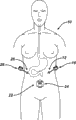
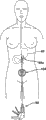
Fig. 1 is the local transparent perspective view of patient's a embodiment, is formed with to enter the hole in patient's stomach wall;
Fig. 2 is the local transparent perspective view of the patient among Fig. 1, is formed with second and enters the hole in patient's umbilicus;
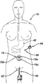
Fig. 3 is the local transparent perspective view of the patient among Fig. 2, is formed with the 3rd and enters the hole in patient's stomach wall;
Fig. 4 is the local transparent perspective view of patient's a embodiment, is formed with to enter the hole in patient's vaginal wall;
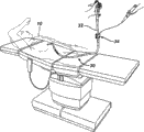
Fig. 5 is the local transparent perspective view of an embodiment that retracts the liver pull device of patient's liver;
Fig. 6 is the local transparent perspective view of an embodiment of dissecting the dissection device of the tissue in patient's stomach;
Fig. 7 is the local transparent perspective view by an embodiment of the dissection device of vagina insertion, and this dissection device is by dissecting the tissue in the patient's stomach with grasper tension tissue;
Fig. 8 is the local transparent perspective view of an embodiment of dissection device, and this dissection device is by dissecting the tissue in the patient's stomach with grasper tension tissue and being entered opening in patient's digestive tract;
Fig. 9 is the local transparent perspective view of patient's a embodiment, is formed with to enter the hole in patient's vaginal wall, is formed with the first abdominal part mouth and is formed with the second abdominal part mouth at patient's stomach wall at patient's umbilicus;
Figure 10 is the perspective view of an embodiment of the passage that forms below of patient's stomach;
Figure 11 is the local transparent perspective view of an embodiment of the sizing tool (sizer) that enters patient's stomach;
Figure 12 is the local transparent perspective view of an embodiment of infeed set-up, this infeed set-up crosscut patient's stomach and insert in patient's body by the hole that enters that forms in patient's vaginal wall;
Figure 13 is the local transparent perspective view of an embodiment of infeed set-up, this infeed set-up crosscut patient's stomach and insert in patient's bodies by many mouthfuls of accesss to plant that are provided with in patient's abdominal part;
Figure 14 is the perspective view of an embodiment of infeed set-up, and this infeed set-up is arranged on the part that initial position is used for crosscut patient's stomach;
Figure 15 is the perspective view by an embodiment of the sealed open of the formation of the infeed set-up among Figure 14;
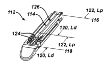
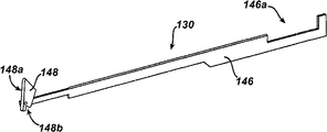
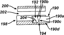
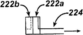
Figure 16 is the perspective view of an embodiment in storehouse (staple cartridge), and this storehouse has cutting near-end, non-and non-fastening zone;
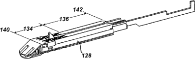
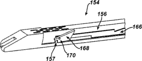
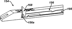
Figure 17 is the perspective view of an embodiment of the cutting assembly that is connected with the storehouse, and this storehouse has cutting near-end, non-and non-fastening zone;
Figure 18 is cutting assembly among Figure 17 and another perspective view in storehouse;
Figure 19 is the cutting assembly among Figure 17 and the top view in storehouse;
Figure 20 is the cutting assembly among Figure 17 and the side view in storehouse;
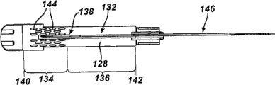
Figure 21 is the exploded view of the cutting assembly among Figure 17;
Figure 22 is the perspective view of the cutting assembly of Figure 17, and at this moment, the cutting element of cutting assembly is in cutting position;
Figure 23 is the perspective view of another embodiment of the cutting assembly that is connected with the storehouse, and this storehouse has cutting near-end, non-and non-fastening zone;
Figure 24 is the cutting assembly among Figure 23 and the side view in storehouse;
Figure 25 is the cutting assembly among Figure 23 and the top view in storehouse;
Figure 26 is the exploded view of the cutting assembly among Figure 23;
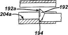
Figure 27 is the side view of the cutting assembly among Figure 23, and at this moment, the cutting element of cutting assembly is in initial non-cutting position;
Figure 28 is another side view of the cutting assembly among Figure 23, and at this moment, cutting element is in initial non-cutting position;
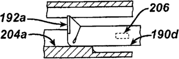
Figure 29 is the perspective view of the local excision in cutting assembly among Figure 23 and storehouse, and at this moment, cutting element is in initial non-cutting position and engages cam member in the storehouse;
Figure 30 is the perspective view of the local excision of the cutting element among Figure 29, and this cutting element rotates to cutting position around cam member from initial non-cutting position;
Figure 31 is the perspective view of the local excision of the cutting element among Figure 30, and this cutting element is in the cutting position that forms around the cam member rotation;
Figure 32 is the perspective view of the local excision of the cutting element among Figure 31, and this cutting element distad pushes in the storehouse at cutting position;
Figure 33 is the side view of local excision of an embodiment of the cutting assembly that is connected with end effector, this end effector has cutting near-end, non-and non-fastening zone and comprises the storehouse and anvil, at this moment, the cutting element of cutting assembly is in initial non-cutting position;
Figure 34 is the end-view of the local excision in cutting assembly among Figure 33 and storehouse;
Figure 35 is the end-view of the local excision of the cutting assembly among Figure 33, and this cutting assembly distad translates across the storehouse, and at this moment, the cutting element of cutting assembly moves to cutting position from initial non-cutting position;
Figure 36 is the end-view of the local excision of the cutting assembly among Figure 34, and this cutting assembly distad translates across the storehouse, and at this moment, cutting element is in cutting position;
Figure 37 is the side view of local excision of another embodiment of the cutting assembly that is connected with end effector, this end effector has cutting near-end, non-and non-fastening zone and comprises the storehouse and anvil, at this moment, the cutting element of cutting assembly is in initial non-cutting position;
Figure 38 is the end-view of the local excision in cutting assembly among Figure 37 and storehouse;
Figure 39 is the end-view of the local excision of the cutting assembly among Figure 37, and this cutting assembly distad translates across the storehouse, and at this moment, the hinge bending of this cutting assembly is to move to cutting position with cutting element from initial non-cutting position;
Figure 40 is the end-view of the local excision of the cutting assembly among Figure 39, and this cutting assembly translates across the storehouse from the distally, and at this moment, cutting element is in cutting position;
Figure 41 is the partial side view of an embodiment of cutting assembly, and this cutting assembly has the cutting element that is connected to push rod with the flexible connector element;
Figure 42 is the side view of local excision of an embodiment of cutting element and push rod, this cutting element is in initial non-cutting position at the far-end of a pair of jaw, this has cutting near-end, non-and non-fastening zone to jaw, and this push rod is distad movable and pass jaw towards cutting element;
Figure 43 is the side view of the local excision of the push rod among Figure 42, and this push rod is connected to cutting element and jaw is passed in the proximad activity, and at this moment, cutting element is in cutting position;
Figure 44 is the side view of the local excision of the push rod among Figure 43, and this push rod is connected to cutting element and jaw is passed in the proximad activity, and at this moment, cutting element is in non-cutting position;
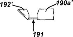
Figure 45 is the side view of an embodiment of cutting element, and this cutting element comprises two members that can pivot and connect;
Figure 46 is the partial side view of an embodiment of push rod, and this push rod can be connected to the cutting element among Figure 45;
Figure 47 is the partial side view of the push rod among Figure 46, and this push rod is connected to the cutting element among Figure 45, and at this moment, cutting element is in cutting position;
Figure 48 is the perspective view of an embodiment of infeed set-up, and this infeed set-up uses the part that sizing tool under one's belt comes crosscut patient's stomach is set;
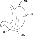
Figure 49 is by the perspective view of an embodiment of the stomach of crosscut;
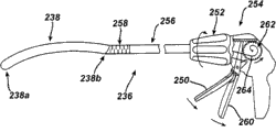
Figure 50 is the perspective view of an embodiment of infeed set-up, and this infeed set-up has the end effector that length prolongs, and this end effector is arranged on initial position, is used for the part of crosscut patient's stomach;
Figure 51 is the partial side view of the infeed set-up among Figure 50;
Figure 52 is the local distal end view of the end effector among Figure 51;
Figure 53 is the partial side view of the end effector among Figure 51; And
Figure 54 is the perspective view of an embodiment of the end effector of infeed set-up, and this infeed set-up has formation a plurality of recesses within it.
The specific embodiment
To describe some exemplary embodiments now provides the complete understanding of structure, function, manufacturing and use principle to apparatus and method disclosed herein.One or more examples among these embodiment are shown in the drawings.It will be understood by those skilled in the art that this paper specifically describes and apparatus and method illustrated in the accompanying drawings are that non-restrictive illustrative embodiment and scope of the present invention only are defined by the claims.The feature that illustrates or describe in conjunction with an exemplary embodiment can with the characteristics combination of other embodiment.This modification and variations are intended to comprise within the scope of the invention.
The invention provides the various illustrative methods and the device that are used to cut with fastening tissue.Though one skilled in the art will appreciate that in conjunction with gastroplasty and described these method and apparatus, these method and apparatus disclosed herein can be used for multiple surgical operation.As limiting examples, can in laparoscopic surgery, use these devices, in this operation, introduce these devices via skin.These method and apparatus can also be used for laparotomy ventrotomy.In addition, surgery device can be configured to pass the arbitrary portion in the health, but in the exemplary embodiment, and surgery device is configured to pass that abdominal part enters the hole or vagina enters the hole.
In one embodiment, the method for carrying out gastroplasty comprises: the one or more middle one or more openings that form by in patient's digestive tract, stomach wall and the vaginal wall enter patient's stomach.In the exemplary embodiment, these method and apparatus are used to carry out Magenstrasse andMill operation, in this operation, a crosscut part of stomach.Various apparatuses can be inserted the intravital various holes that enter of patient and carry out some step, for example strain and cut and organize, stomach is carried out sizing and crosscut, observation operative site etc.In the exemplary embodiment, the surgery device that is provided can be used for to small part crosscut stomach.This device can have end effector, this end effector can joining tissue and can be activated, the tissue that engages in the distal portions with the cutting tip executor and/or to the one or more securing members of this organizations, and the tissue that does not engage in cutting tip executor's the proximal part and/or to this organizations securing member.Like this, in Magenstrasse and Mill operation (not having the stomach between the stomach function regulating pylorus of abundant crosscut stomach His angle), do not have the device of the tissue that engages in the cutting and/or the proximal region of fastening end effector can be used to engage gastral cavity and do not cut gastral cavity, and alternatively, this device can cut and the fastening tissue that leaves gastral cavity, i.e. the tissue that engages in Zhuan Zhi the distal portions.Use this device can reduce needs to the original position that stomach 40 is measured, calculating, labelling wait to determine the stomach crosscut, this is because the original position that this device can normally be scheduled to crosscut by the non-cutting and/or the non-fastening zone of the near-end with predetermined length.Adopt similar mode, this surgery device can be used for any surgical operation, as long as these surgical operations need cut and/or the proximal part of the distal portions of the fastening tissue that is engaged by end effector rather than the tissue that engaged by end effector.
As the skilled person will appreciate, can adopt any way to allow the patient prepare for the operation of stomach plastic surgery.For example, can be in order to perform the operation with complete calmness of patient or associated with conscious sedation.The non-limiting example of associated with conscious sedation system is found in the U.S. Patent application No.2006/0042636 of " Oral Nasal Cannula " (mouth and nose chamber sleeve pipe) by name of submitting on June 21st, 2005, the U.S. Patent No. 6 of " the ApparatusAnd Method For Providing A Conscious Patient Relief From PainAnd Anxiety Associated With Medical Or Surgical Procedures " by name that announces on October 26th, 2004 (for clear-headed patient's alleviation misery relevant and the equipment and the method for anxiety) with internal medicine or surgical operation, 807,965, the U.S. Patent No. of submitting on April 10th, 2,007 7 that is called " Apparatus For Drug Delivery In Association With Medical OrSurgical Procedure " (equipment that the medicine relevant with internal medicine or surgical operation sent), 201,734 and the U.S. Patent No. 7 of " Method For Drug Delivery In Association With Medical OrSurgical Procedures " (method that the medicine relevant with internal medicine or surgical operation sent) by name submitted on July 24th, 2007,247,154, it is incorporated into way of reference in full in view of the above.
In an exemplary embodiment of gastroplasty operation shown in Figure 1, in patient 10 stomach wall 14, form the abdominal part opening or enter hole 12.During gastroplasty, as shown in the figure, patient 10 preferably is positioned on diagnosis and treatment bench 18 but substantially horizontal calculi position, thereby can unimpededly enter patient's abdomen area.Other accompanying drawing of Fig. 1 and this paper discussion is simplified with convenient statement and the device that the given time in patient 10 and/or the surgical procedures exists is not shown always, for example before device and any other necessaries (for example patient monitoring apparatus, safety device, video-frequency monitor etc.) shown in one or more described accompanying drawings.In addition, described is to carry out gastroplasty by the surgeon, but as the skilled person will appreciate, can carry out any one or a plurality of part in the operation such as one or more medical professionals of surgeon, surgical operation assistant, nurse etc.In addition, though what illustrate is female patient, patient 10 can be a sex.
As shown in Figure 1, can in stomach wall 14, form the abdominal part opening or enter hole 12, although also can patient 10 intravital use Anywhere and/or form enter the hole.Abdominal part enters the form that hole 12 can be circular basically cutting opening (circular otomy), and perhaps it can be the otch of percutaneous.Those skilled in the art will know, term used herein " cutting opening " is intended to contain opening or enters the hole, described opening or enter that the hole can hold access to plant with retractor or orientable other device in entering the hole, the described external diameter scope that enters the hole is about 15mm to 35mm, for example about 25.4mm (about 1 inch).Those skilled in the art also will know, term used herein " opening of percutaneous " or " percutaneous enter hole " are intended to contain the intravital relatively little opening of patient or enter the hole, and described opening or the diameter range that enters the hole are preferably about 3mm to 5mm.
As the skilled person will appreciate, can form abdominal part by any means and enter hole 12.As shown in the figure, use the trocar 16 to form abdominal part and enter hole 12.The trocar 16 can comprise any intubate, and described intubate can cut and organize and have hollow inside, and surgical operating instrument can enter by this hollow inside and penetrate the tissue of being cut in patient's body.The trocar 16 can comprise the optics top, and this optics top is configured to: for example, use to be inserted in the trocar 16 its and to be provided with the finder (for example, peritoneoscope) of watching element, make and can see stomach wall 14 when the trocar 16 when stomach wall 14 passes.Whenever peritoneoscope 20 can be inserted the trocars 16, be included in during the piercing tissue or after the trocar 16 thrusts stomach wall 14.Those skilled in the art also can know, gastroplasty employed any one or a plurality of finder can comprise that it is provided with any surgery device of watching element (for example, lens).The limiting examples of finder comprises endoscope, peritoneoscope, gastroscope and colonoscope.The trocar 16 can be configured to: make that rigidity or flexible surgical operating instrument (for example, grasper, cutting device, finder etc.) can be from its abdominal cavities across and into the patient.Those skilled in the art will know, term used herein " grasper " is intended to contain any surgical operating instrument, these surgical operating instruments can be firmly grasped and/or conjunctive tissue and manipulating tissue thus, and these apparatuses for example are tweezers, retractor, moving jaw, magnet, binding agent, stay sutures device etc.
In one embodiment, insert the flexible joint that patient's 10 intravital finders can comprise one or more distally, these joints can help finder in patient's 10 intravital orientations.The non-limiting example of the flexible joint on the surgery device is found in the U.S. Patent application No.12/242 of " Methods And Devices For PerformingGastrectomies And Gastroplasties " by name (carrying out method and apparatus of gastrectomy and gastroplasty) of JIUYUE in 2008 submission on the 30th, 333, the U.S. Patent application No.12/242 that is called " Methods And Devices For Performing GastrectomiesAnd Gastroplasties " (carrying out method and apparatus of gastrectomy and gastroplasty) in JIUYUE in 2008 submission on the 30th, 353 and the U.S. Patent application No.12/242 of " Methods And Devices For Performing Gastroplasties Using AMultiple Port Access Device " by name (the using the method and apparatus of many mouthfuls of accesss to plant execution gastroplastys) of submitting in 30th in JIUYUE in 2008,381, the full text of these patent applications is incorporated into way of reference in view of the above.Usually, flexible joint can be for can deflection or crooked.Flexible joint can activate (for example, movable when adjoining with one or more adjacent structures) passively and/or activate (for example, by handling machinery and/or manual actuation mechanism) on one's own initiative.Flexible joint can be configured to when activating along single direction bending, and can optionally select single direction, and is for example left and right, upper and lower etc.If surgery device comprises a plurality of flexible joints, then each flexible joint can along with other flexible joint of surgery device in the identical or different any direction of any flexible joint activate individually.Actuating mechanism can be configured to control the activity along selected direction.As the skilled person will appreciate, can adopt any way that is same to each other or different to each other to form flexible joint.For limiting examples, flexible joint can be made by flexible material, can comprise being formed with within it and help flexible one or more features (for example, a plurality of otch, slit etc.) and/or can form by a plurality of linkages (linkage) of movable connection each other.In alternate embodiment, finder can have two or more flexible joints (use or do not use sleeve pipe) along its longitudinal axis in different positions, thus make finder with respect to the longitudinal axis of finder along both direction bending at least.The limiting examples of many bent finders is Olympus Corp (Olympus Corp.of Tokyo, R-Scope XGIF-2TQ260ZMY Japan) that can derive from the Tokyo.
Can randomly except abdominal part enters hole 12, can also in patient's stomach wall 14, form one or more openings or enter the hole.Each other abdominal part enters the hole can have size, shape and structure arbitrarily, but in the exemplary embodiment, and described other abdominal part enters the hole and is opening via skin.Can and/or form any other abdominal part afterwards before abdominal part enters hole 12 formation and enter the hole, but in the exemplary embodiment, after abdominal part enters hole 12, form any other abdominal part and enter the hole, insert the surgery device that abdominal part enters hole 12 the patient abdominal cavity is inflated so that can use in advance, as discussed further below.
Fig. 2 illustrates within it except the abdominal part that is provided with the trocar 16 enters hole 12, the other abdominal part opening that forms in patient's 10 bodies or an embodiment who enters hole 22.Other abdominal part opening 22 can have arbitrary dimension, shape and structure, but in the exemplary embodiment, it is cutting openings that other abdominal part enters hole 22, and roughly is arranged in patient's umbilicus.Less less body cavity opening can improve the rehabilitation of patients time usually and reduce pain, can be favourable so only utilize single abdominal incision (for example, the otch in the umbilicus) to operate.Umbilicus is the thinnest and blood vessel is minimum, and is very good hiding zone in the stomach wall 14.The umbilicus otch enlarges easily, does not for example sacrifice attractive in appearance to take out bigger specimen significantly and increases the chance that wound complication occurs.As the skilled person will appreciate, can form other abdominal part opening 22 by any-mode.(for example adopting any way, cutting device by use such as pin cutter, scalpel, billhook etc.) generating other abdominal part enters after the hole 22, many mouthfuls of accesss to plant 24 with two or more seals can be arranged in the stomach wall 14, surgical operating instrument can insert this two or more seals.Many mouthfuls of accesss to plant 24 can have any structure; the U.S. Patent application No.12/242 of " the Methods AndDevices For Performing Gastroplasties Using A Multiple PortAccess Device " by name in JIUYUE in 2008 submission on the 30th that mention before but the non-limiting example of many mouthfuls of accesss to plant is found in (using many mouthfuls of accesss to plant to carry out the method and apparatus of gastroplastys); 381 and the U.S. Patent application No.2006/0247673 of " Multi-port Laparoscopic Access Device " (the many mouthfuls of peritoneoscope accesss to plant) by name submitted on April 5th, 2006; the U.S. Patent application No.12/242 that is called " Surgical Access Device " (surgical access devices) in JIUYUE in 2008 submission on the 30th; 765; the U.S. Patent application No.12/242 that is called " SurgicalAccess Device with Protective Element " (surgical access devices) in JIUYUE in 2008 submission on the 30th with protective element; 711; the U.S. Patent application No.12/242 that is called " Multiple Port Surgical Access Device " (many mouthfuls of surgical access devices) in JIUYUE in 2008 submission on the 30th; 721 and the U.S. Patent application No.12/242 of " Variable Surgical Access Device " (the variable surgical operation access to plant) by name submitted in 30th in JIUYUE in 2008; 726, the full text of these patent applications is incorporated into way of reference in view of the above.
Fig. 3 illustrates another embodiment, in this embodiment, except abdominal part enters hole 12 and other abdominal part enters the hole 22, has also formed the second other abdominal part opening or enter hole 26 in patient's stomach wall 14, is used to enter patient's abdominal cavity.The second other abdominal part opening 26 can have virtually any size, shape and structure, but in the exemplary embodiment, and it is substantially the same that the second other size that enters hole 26, shape and the structure and abdominal part enter hole 12.Other abdominal part enters hole 22,26 and can relative to each other and with respect to the abdominal part opening 12 that is provided with the trocar 16 in it form by any order.Abdominal part enters the stomach wall 14 that hole 12,22,26 can be configured to pass the patient anywhere, but as shown in the figure, enters hole 12,26 lateral alignment on the relative two sides of patient's abdominal part basically via the abdominal part of skin.As shown in the figure, be provided with entering hole 22 and can entering not lateral alignment of hole 12,26 (for example, in umbilicus) of many mouthfuls of accesss to plant 24 in it, and can enter at abdominal part between the hole 12,26 via skin with abdominal part via skin.Like this, grasper can insert abdominal part via skin and enter in the hole 12,26 at least one, and can be so that tissue can be with respect to surgical operating instrument (for example, cutting device) lateral angle (transverse angle) is strained in patient's 10 bodies, and this surgical operating instrument inserts in patient's 10 bodies by umbilicus.As the skilled person will appreciate, can adopt any-mode to form to pass the second other hole 26 that enters that is used to enter the patient abdominal cavity of patient's stomach wall 14, but in the exemplary embodiment, use the trocar 28, to form the second other hole 26 that enters with the above-mentioned similar mode of discussing at other abdominal part opening 12 (using the trocar 16 to generate) of mode via skin.Insertion can comprise any sleeve pipe that is same to each other or different to each other via the sleeve pipe 16,28 of the abdominal part opening 12,26 of skin.
As the skilled person will appreciate, can adopt any way to form the patient 10 intravital holes that enter.The non-limiting example that can be used for forming the trocar that enters the hole is found in the U.S. Patent Publication No.2007/0260273 of " Endoscopic Translumenal SurgicalSystems " (endoscope is through the shell surgery systems in chamber) by name of submitting on May 8th, 2006, and its full content is incorporated into way of reference in view of the above.The exemplary embodiment of the trocar can comprise trocar housing and trocar cannula (trocar sleeve) or trocar sheath, this trocar housing can make surgery device to pass from it, this trocar cannula or trocar sheath engage sleeves bobbin housing or extend from trocar housing.The trocar can also comprise obturator, and this obturator can pass trocar housing and trocar cannula.Obturator can have inner chamber and far-end, and this inner chamber passes from it and is used for admitting finder and/or other operation device within it, and this far-end can piercing tissue.The trocar can be slidably disposed on the obturator top, and can be as the occupy-place sign after the trocar inserts tissue and removes obturator. can be used for forming the U.S. Patent application No.12/242 of " Methods And DevicesFor Performing Gastrectomies And Gastroplasties " by name (the carrying out method and apparatus of gastrectomy and gastroplasty) of submitting in 30 days September in 2008 that non-limiting example that belly enters the cover in hole and obturator mentions before being found in; 333 and the U.S. Patent application No.12/242 of " Methods And Devices For PerformingGastrectomies And Gastroplasties " by name (the carrying out method and apparatus of gastrectomy and gastroplasty) of submitting on September 30th, 2008,353.
As the skilled person will appreciate, in case realized entering the abdominal cavity, the surgeon just can be by the opening in patient's abdominal part to the inflation of patient abdominal cavity, to expand the abdominal cavity and the bigger work space that can handle easilier is provided.For example, the surgeon can inflate to the abdominal cavity by making fluid (for example, nontoxic carbon dioxide) pass the trocar 16 under the situation of pressurized.As the skilled person will appreciate, this fluid can have the pressure limit of about 10-15mm Hg or have any other pressure.The trocar 16 can comprise a plurality of sealing members, and these sealing members are used to prevent that the fluid that charges into from passing through the trocar 16 and overflowing from the abdominal cavity.The limiting examples of not using the sealing shroud bobbin of sealing member is SurgiQuest company (SurgiQuest, Inc.of Orange, SurgiQuest AirSeal Connecticut) that can derive from orange county, Connecticut
TMIf the one or more openings except the abdominal part that is provided with the trocar 16 in it enters hole 12 pass 14 formation of patient's stomach wall and make surgery device (for example, the trocar) passes from it, then this device can provide sealing member, and the fluid that is used to prevent to charge into is from its abdominal cavity of overflowing.
As shown in Figure 4, except entering the hole or substitute one or more abdominal paries, one or more abdominal paries enter the hole, the surgeon can form vaginal opening or enter hole 30 in patient 10 vaginal wall, thereby generates opening between vagina and patient's abdominal cavity, is used to enter the abdominal cavity.As the skilled person will appreciate, can adopt any way to form the vagina that passes vaginal wall and enter hole 30.In the exemplary embodiment, the trocar 34 can insert vaginal wall and enter hole 30 to form vagina, generates opening thus between vagina and patient's abdominal cavity.
As mentioned above, can use finder in gastroplasty, for example endoscope 32.Enter before hole 30 forms at vagina, endoscope 32 can be pushed into vagina, and/or enters after hole 30 forms at vagina, and endoscope 32 can be pushed into vagina and enter the trocar 34 in the hole 30, thereby in the surgery intra-operative can be observed patient's body.Form vagina before or after can entering hole 12 at the abdominal part in forming Fig. 1 and enter hole 30, but in the exemplary embodiment, after the formation abdominal part enters hole 12, form vagina and enter hole 30, so that can enter hole 12 to the inflation of patient's abdominal cavity by abdominal part in advance.Before the formation vagina enters hole 30, as skilled in the art will appreciate, can use surgical operating instrument (sight glass and/or the one or more stitching thread that for example, add weight) to enlarge patient's vaginal opening.Vagina enters hole 30 can have Any shape and size, it is that the surgical operating instrument (for example, retractor, finder, surgical operation stiching instrument, clamp etc.) of about 5mm to 18mm passes through from it that but vagina enters that the diameter in hole 30 is preferably about 18mm and can makes diameter range.
At the surgery intra-operative, patient's stomach can be difficult to fully be entered.During gastroplasty, can retract patient's liver, the effect that better enters patient's stomach to help the surgeon to obtain.Though can retract liver in the perioperative any time of surgery, in the exemplary embodiment, in finder being inserted patient's 10 bodies, retract liver afterwards, thereby before retracting liver He during retracting liver, can observe the abdominal cavity.Though use finder (introducing in the abdominal cavity) by the opening in the stomach wall 14 realize liver by before retracting, during and/or afterwards visuality, the visuality of using the finder introduced by vagina to realize can increase the abdominal part work space and/or reduce " chopsticks " effect that the apparatus by the abdominal part introducing causes.Can adopt any way that skilled in the art will recognize that to retract liver, but at least one device that preferably, use the abdominal part form before by (for example) to enter hole 12, to enter insertion patient's 10 such as hole abdominal cavity by other abdominal part openings, by vagina retracts liver.In addition, as the skilled person will appreciate, can drainage system be set (for example at patient's intraperitoneal, Penrose drainage tube, Jackson-Pratt drainage tube etc.), be used for helping at the fixing liver and/or draw and can accumulate in Intraabdominal too much fluid of surgery intra-operative (especially at liver by after retracting).
In the exemplary embodiment, can be used to retract patient's liver such as the retractor device of Nathanson liver retractor.Fig. 5 shows and uses Nathanson liver retractor 36 that patient 10 liver 38 is retracted so that its liver away from patient 10 stomach 40 retracts an embodiment of operation.As the skilled person will appreciate, the surgeon can use Nathanson liver retractor 36 with required retract the position " catch on " liver 38 and fixedly liver 38 so that it is away from stomach 40.Nathanson liver retractor 36 can directly insert abdominal part and enter hole 12 (as shown in the figure), perhaps Nathanson liver retractor 36 can be pushed the hollow device that is used to enter the patient abdominal cavity, for example push the trocar that inserts by vagina, push many mouthfuls of accesss to plant, push sleeve pipe etc.Though not shown in Fig. 5, be to use to push patient's 10 intravital finders can be observed the patient at liver during retracting abdominal cavity.The grasper (not shown) can be pushed stomach wall 14, for example directly push many mouthfuls of accesss to plant 16, push the trocar etc., thereby help to retract liver 38 and/or (in other words conj.or perhaps) helps gastroplasty by the service aisle of finder.
Can be randomly, as shown in Figure 5, the support member 42 of patient 10 outsides can be used for Nathanson liver retractor 36 is installed to the diagnosis and treatment bench 18 that patient 10 leans on, although also can use any other support member, as long as these support members are used for liver retractor fully.By Nathanson liver retractor 36 is installed, the surgeon need not keep Nathanson liver retractor 36 in place at the surgery intra-operative always, make the surgeon need not note other operating thing thus, and/or reduce required operation room work personnel amount.The U.S. Patent application No.12/242 of " Methods And Devices For Performing Gastrectomies AndGastroplasties " by name (carrying out method and apparatus of gastrectomy and gastroplasty) of submitting in 30th in JIUYUE in 2008 that the non-limiting example of support member is mentioned before being found in, 333 and the U.S. Patent application No.12/242 of " Methods And Devices For Performing Gastrectomies AndGastroplasties " by name (the carrying out method and apparatus of gastrectomy and gastroplasty) of submitting in 30th in JIUYUE in 2008,353.Support member can have various sizes, shape and structure, but as shown in the figure, support member 42 can comprise adapter 44 and flexible arm 46, and flexible arm 46 can be connected to the device of installation and can be connected to adapter 44 in its end tip.As the skilled person will appreciate, flexible wall 46 is usually configured to mobilizable, and the position of the feasible device of installing is adjustable with respect to diagnosis and treatment bench 18.As shown in the figure, adapter 44 can be mobilizable, and can (as shown in the figure) cooperate the platform support, and this support is connected to diagnosis and treatment bench 18 and comprises that platform track 48 and its each end tip are connected to the support 50 of platform track 48 and adapter 44.In alternate embodiment, except diagnosis and treatment bench 18 or alternative diagnosis and treatment bench 18, support member can install to another rock-steady structure near patient 10, for example wall, roof, stand on the absolute construction (being similar to infusion stand or mike stand, overhead jaw) on floor etc.Nathanson liver retractor 36 can be installed in the perioperative any time of gastroplasty, and it is installed in can be any time adjustable and/or disengagement, but in the exemplary embodiment, liver 38 is arranged in patient's 10 bodies required retract the position before, Nathanson liver retractor 36 is installed.Nathanson liver retractor 36 and/or support member 42 (for example, flexible arm 46, adapter 44 and/or support 50) can be adjusted to and help liver 38 to move to its required position that retracts.
One skilled in the art will appreciate that support member can be used to that Nathanson liver retractor 36 is installed and/or the gastroplasty that do not need always to start to handle during any other surgical operating instrument of using.In single surgical operation, can use a plurality of support members.
Liver retractor device and liver (for example retract method, use beats out the device that a spike devices is used for liver with one or more hobnail and use inserts many mouthfuls of accesss to plant and retracts liver) various other limiting examples be found in the U.S. Patent application No.12/242 of " Methods And Devices For Performing Gastrectomies AndGastroplasties " by name (carrying out method and apparatus of gastrectomy and gastroplasty) that JIUYUE in 2008 submitted on the 30th, 333 and the U.S. Patent application No.12/242 of " Methods And Devices For Performing Gastrectomies AndGastroplasties " by name (the carrying out method and apparatus of gastrectomy and gastroplasty) of submitting in 30th in JIUYUE in 2008, the U.S. Patent application No.12/242 of " Methods And Devices For Performing Gastroplasties Using AMultiple Port Access Device " by name (using many mouthfuls of accesss to plant to carry out the method and apparatus of gastroplastys) of 353 and 2008 on JIUYUE submission in 30,, 381.
Before crosscut stomach 40, stomach 40 can separate with the tissue that is connected to stomach 40 (for example, the adhesion on nethike embrane, vascular, the stomach 40 etc.), so that stomach 40 does not have substrate.As the skilled person will appreciate, the tissue that can use any one or a plurality of dissection device will be connected to stomach 40 separates with stomach 40.Those skilled in the art will know, term as used herein " dissector ", " dissection device " or " dissection surgical operating instrument " are intended to comprise any surgical operating instrument, this surgical operating instrument can cut and organize, and it for example is dissecting knife, ultrasound knife, blunt dissection, the cautery tool that can cut and organize, shears, endoscope's linear cutter, surgical operation stiching instrument etc.Can adopt any way that required tissue is separated with stomach 40, but in the exemplary embodiment, big curved part is cut in the contiguous stomach 40 of surgeon, thereby makes nethike embrane not have substrate.Dissector can be introduced in patient's 40 bodies by any hole (generate naturally or generate by surgical operation) that enters.In an embodiment shown in Figure 6, dissector 52 can insert abdominal part and enter the trocar 16 in the hole 12 and be used for from stomach 40 excision nethike embranes 54.As shown in the figure, in this illustrated embodiment, dissector 52 has the end effector 52a that comprises far-end, and this far-end has a pair of adjustable clamp that can cut and organize.For by the required tissue of being dissected, between the His angle 40b of the gastric antrum 40a of stomach 40 and stomach 40, can observe and/or enter the rear side of stomach 40.
In the exemplary embodiment, can use grasper 56 with nethike embrane 54 and/or the tension of any other required tissue, dissector 52 is dissected undertissue from stomach 40 simultaneously.Can adopt any way that grasper 56 is introduced in patients' 10 bodies, for example by many mouthfuls of accesss to plant, by via the trocar in the abdominal part opening of skin, enter hole etc. by vagina.Usually, the surgeon can be delivered to grasper 56 from dissector 52 with tissue, catches tissue with grasper 56, promotes grasper 56 and strains the tissue of being firmly grasped, and use dissector 52 anatomical tissues.The surgeon can repeat this process for several times, so that stomach does not have substrate.Though only show a grasper in the embodiment shown in fig. 6, the surgeon can use the grasper of any amount, can adopt any way that these graspers are inserted the patient abdominal cavity.If finder inserts patient's intraperitoneal, then the surgeon can use finder to realize visuality, for example helps location grasper 56 and/or other grasper.Alternatively or in addition, finder can be during being dissected required tissue and/or is observed the rear side of stomach 40 afterwards.
Fig. 7 illustrates the embodiment that uses a plurality of graspers, wherein, can use second trocar 60 to form second abdominal part and enter hole 58 (for example, via the opening of skin), this forms abdominal part about the use trocar 16,28 to enter the method in hole 12,26 similar with above-mentioned.The surgeon can insert any one or a plurality of required surgical operating instrument simultaneously and/or make it sequentially enter hole 58 by second abdominal part, and is provided with second trocar 60 within it or second trocar 60 is not set.Just for limiting examples, the surgeon can the grasper that at least one is other pushes second abdominal part and enters hole 58, and second grasper and the grasper 62 that inserts femshield bobbin 64 are used collaboratively, is used to strain nethike embrane.In certain embodiments, the surgeon can only use the grasper that inserts stomach wall 14 (for example, insert second abdominal part and enter hole 58) and not use the grasper that inserts by vagina.Perhaps, the surgeon can push other grasper the other hole that enters, and for example, pushes vagina by the service aisle of endoscope 66 and enters the hole, pushes abdominal part or vagina enters many mouthfuls of accesss to plant that insert in the hole etc.In certain embodiments, can be inserted vaginas by one or more graspers of anatomical tissue and enter the hole, for example, insert many mouthfuls of accesss to plant and do not insert patient's abdominal part being used to strain.
Shown in another embodiment among Fig. 8, use the many mouthfuls of accesss to plant 68 that are provided with in patient's abdominal part, dissector 73 can be pushed in patient's 10 bodies and make dissector 73 be used to dissect nethike embrane 54.Grasper 70 per os can be pushed stomach 40 by finder 72, push digestive tract opening 74 and push patient 10 abdominal cavity, with promptly and tension nethike embrane 54.Can adopt any way that those skilled in the art will know that to form digestive tract opening 74.Digestive tract opening 74 can be formed on any position of stomach 40, but its preferably be formed on stomach 40 after crosscut, will form a part of stomach telescopic that part of on, with any device of helping to insert by digestive tract opening 74 before crosscut, in the crosscut process and keep permanent location after the crosscut.Digestive tract opening 74 is illustrated as being formed in the coat of the stomach, but digestive tract opening 74 can be formed on the gastral any position of patient, for example, and in coat of the stomach, medium at intestinal wall.Digestive tract opening 74 can have Any shape and size.In the crosscut process, if digestive tract opening 74 is not included in the part with the isolating stomach substrate of the remainder of stomach 40, then digestive tract opening 74 can be closed by any way that those skilled in the art will know that, for example, utilize the surgical operation stiching instrument that is inserted into many mouthfuls of accesss to plant that insert through abdominal part.
Fig. 9 shows the alternate embodiment of utilizing many mouthfuls of accesss to plant 76, and many mouthfuls of accesss to plant 76 roughly are positioned at patient 10 umbilicus place, are used to dissect the tissue that is attached to stomach 40.In this exemplary embodiment, the surgeon can utilize finder to enter among mouth 78a, 78b, the 78c of many mouthfuls of accesss to plant first and observe surgical site, utilize second among dissector inlet port 78a, 78b, the 78c to dissect the tissue that is attached to stomach 40, and utilize the 3rd among grasper inlet port 78a, 78b, the 78c to strain the tissue of being dissected.Alternatively or in addition, enter grasper that the trocar 80 in hole 82 enters and/or enter the grasper that the trocar 84 in hole 86 enters and can be used for straining the tissue of being dissected by being inserted into vagina via skin by being inserted into abdominal part via skin.At least inserting grasper that abdominal part via skin enters hole 86 can allow to be organized in patient's 10 bodies to be tightened up with respect to the lateral angle that is inserted into patient's 10 intravital surgical operating instruments (for example, cutting device) by many mouthfuls of accesss to plant 76 at the umbilicus place.
In certain embodiments, shown in an embodiment among Figure 10, the below that dissector is used in stomach 40 forms opening 88.Opening 88 can have appoints and size, shape and structure, but in illustrated exemplary embodiment, opening 88 can comprise passage, and described passage has constant substantially diameter and has almost circular shape of cross section along its longitudinal length.The surgeon can (for example) come from the rear side of 40b ground, gastric antrum 40a to His angle observation stomach 40 by at least a portion longitudinal length that finder is pushed opening 88.Can use any dissector to form opening 88, the U.S. Patent application No.12/242 of " the Methods AndDevices For Performing Gastroplasties Using A Multiple PortAccess Device " by name that example was submitted in JIUYUE in 2008 as previously mentioned on the 30th (utilizing many mouthfuls of accesss to plant to carry out the method and apparatus of gastroplasties), the exemplary dissector of describing in 381.
Dissect from nethike embrane 54 in case be attached to organizing expectably of stomach 40, and optionally form the opening 88 of stomach 40 belows, then stomach 40 can be by crosscut.Those skilled in the art will know that and to utilize any one or a plurality of infeed set-up to come crosscut stomach 40.Those skilled in the art also will know, term used herein " crosscut device ", " infeed set-up " or " crosscut surgical operating instrument " are intended to contain can be individually or with the surgery device of compound mode cutting and fixing organization, for example, can cut surgical operation stiching instrument with suture tissue.The non-limiting example of surgical operation stiching instrument is found in the U.S. Patent No. 5 of " Surgical Anastomosis Stapling Instrument " (the surgical stapling art suture instruments) by name announced February 14 nineteen ninety-five, 285,945, the U.S. Patent No. 6 of " Surgical Stapling Instrument Incorporating A FiringMechanism Having A Linked Rack Transmission " (assembling has the surgical stapling instrument of the trigger mechanism of continuous rack gearing) by name of announcing on June 14th, 2005,905,057, the U.S. Patent No. 7 of " Surgical InstrumentIncorporating An Articulation Mechanism Having Rotation AboutThe Longitudinal Axis " (surgical operating instrument that comprises the articulation mechanism that rotates around longitudinal axis) by name of JIUYUE in 2006 announcement on the 26th, 111,769, the U.S. Patent No. 6 of " Surgical Stapling Instrument Incorporating An ArticulationJoint For A Firing Bar Track " (surgical stapling instrument that comprises articulated joint that is used for firing bar track) by name of JIUYUE in 2004 announcement on the 7th, 786,382, the U.S. Patent No. 6 of " the Surgical Instrument With A Lateral-MovingArticulation Control " by name that announced on January 3rd, 2006 (surgical operating instrument) with horizontal Movable joint control, 981,628, the United States Patent (USP) U.S.Patent No.7 of " the SurgicalStapling Instrument Incorporating A Tapered Firing Bar ForIncreased Flexibility Around The Articulation Joint " by name that announced on June 6th, 2006 (at the surgical stapling instrument that comprises taper emission bar of the increased flexibility around the articulated joint), 055,731, the U.S. Patent No. 6 of " the Surgical Stapling Instrument Having Articulation JointSupport Plates For Supporting A Firing Bar " by name that announced on November 15th, 2005 (in order to support the surgical stapling instrument with articulated joint gripper shoe of emission bar), 964,363, the U.S. Patent No. 6 of " the Surgical StaplingInstrument With Multistroke Firing Incorporating An Anti-Backup Mechanism " by name that announced on November 1st, 2005 (surgical stapling instrument) with pilosity emission of anti-supporting mechanism, 959,852, the U.S. Patent No. 7 of " the Surgical Stapling Instrument Having Multistroke Firing WithOpening Lockout " by name that announced October 14 in 2008 (surgical stapling instrument) with pilosity emission of unlimited blockade, 434,715, the U.S. Patent No. 7 of " the Surgical Stapling Instrument Having Multistroke FiringIncorporating A Traction-Biased Ratcheting Mechanism " by name that announced on February 21st, 2006 (surgical stapling instrument that comprises the pilosity emission of pull bias ratchet mechanism), 000, the U.S. Patent No. 7 of " the Surgical StaplingInstrument Incorporating A Multistroke Firing PositionIndicator And Retraction Mechanism " by name that announced on April 29th, 819 and 2008 (surgical stapling instrument that comprises multiple emission register guide and ratchet mechanism), 364,061, the full text of these patents is incorporated into application mode in view of the above.
The crosscut device can have any size and shape, but in the exemplary embodiment, if crosscut device transvaginal enters in patient's 10 bodies, then the crosscut device preferably has long relatively longitudinal length (for example, at least about 4 feet), and has at least one flexible joint.Non-limiting example with crosscut device of at least one flexible joint is found in the U.S. Patent application No.12/242 of " Methods And Devices For PerformingGastroplasties Using A Multiple Port Access Device " by name in JIUYUE in 2008 submission on the 30th (using many mouthfuls of accesss to plant to carry out the method and apparatus of gastroplastys) of mentioning before, 381.Those skilled in the art will know that the crosscut device can be inserted in patient's 10 bodies by any opening, for example, by abdominal part enter the hole, vagina enters hole, natural tract etc., these openings are provided with or are not provided with the trocar or many mouthfuls of accesss to plant within it.In addition, at least one grasper that inserts by the intravital any openings of patient 10 can be used for straining stomach 40 and/or sizing tool (sizer) is remained on the desired position along lesser gastric curvature when stomach 40 is by crosscut.
In the exemplary embodiment, the crosscut device can cut and organize and one or more fastener delivery are arrived tissue.Specifically, the crosscut device can have the end effector that can engage with tissue at its far-end.End effector can have non-cutting zone, makes the crosscut device can cut the middle tissue that engages of first's (for example, distal portions) at end effector, and does not cut the middle tissue that engages of second portion (for example, proximal part) at end effector.End effector also can have non-fastening area, and this zone can be positioned at same position substantially with non-cutting zone, makes tissue that device engages in can the distal portions of fastening end effector and the tissue in the proximal part of fastening end effector not.Having the non-cutting zone of near-end and/or basic and the non-cutting zone of described near-end, to be in the device of the non-fastening area of near-end of same position especially effective in a part of only cutting stomach 40 is performed the operation with the Magenstrasse and Mill that forms the stomach oversleeve.This device can be used for: utilize the periphery at stomach 40 to begin crosscut with the device that stomach 40 engages at least, described device begins at least a portion of crosscut stomach 40 at a certain distance from the gastric antrum 40a of stomach and does not cut the boundary member of the stomach of described joint.To discuss exemplary crosscut device below in more detail.
In any moment before crosscut stomach 40, the surgeon is adjustable stomach 40 is to form stomach tube or stomach oversleeve in stomach 40.In the exemplary embodiment, though described oversleeve can form before or after passage 88 or the generation of described opening, but can below stomach 40, generate passage 88 and generate the antetheca pass stomach 40 and the opening of rear wall after form the stomach oversleeve, this is in following further discussion.As shown in figure 11, the surgeon can be incorporated into diameter-setting equipment 106 in the stomach 40, will form that part of sizing of the stomach 40 of stomach oversleeve with help.Can diameter-setting equipment 106 be introduced in the stomaches 40 according to any way, but in the exemplary embodiment, diameter-setting equipment 106 per os enter into stomach 40, for example, mouth 108 and esophagus 110 by patient 10 are incorporated in the stomach 40.Those skilled in the art will know that term used herein " sizing tool ", " diameter-setting equipment " or " sizing apparatus " are intended to contain any surgical operating instrument that can indicate required stomach oversleeve zone, for example, bougie, finder, conduit etc.Sizing tool 106 can randomly comprise lamp at its far-end, to help the surgeon sizing tool 106 is pushed esophagus 110 and sizing tool 106 is positioned at desired location in the stomach 40.The size of sizing tool and shape can be substantially corresponding to the size and the shapes that needs are formed on patient's 10 intravital stomach oversleeves, and like this, the surgeon can select to have substantially the sizing tool corresponding to any size, shape and the structure of required oversleeve size.In the exemplary embodiment, sizing tool 106 is flexible surgical operating instruments, it has the shape of general cylindrical and has constant substantially diameter along the longitudinal length of sizing tool, and described diameter is (about 9.3 to 14mm) in about scope of 28 to 42French.
After crosscut stomach 40 at least in part, can in stomach 40, regulate sizing tool 106, sizing tool 106 is arranged in the size of indicating the stomach oversleeve generally and the sizing position of position.In the exemplary embodiment, the sizing tool 106 that is in the sizing position extends and enters into the pylorus 93 of stomach 40 along the little curved 40c of stomach 40, thereby the 106a of distal-most end at least of sizing tool 106 extends to the sphincter of pylorus or the pyloric valve of pylorus 93.Will know as those skilled in the art, can adopt any way in patient's 10 bodies, to regulate sizing tool 106.In the exemplary embodiment, can utilize and enter flexibility and/or the rigidity grasper that the hole is inserted in the stomach 40 by abdominal part and in stomach 40, regulate sizing tool 106.Grasper can comprise end effector, described end effector has two relative, mobilizable jaws, in case described jaw can sizing tool 106 fully enters in patient's 10 bodies and described grasper can handle it time, described jaw is firmly grasped sizing tool 106 and is made sizing tool 106 activities.Be inserted into finder in the stomach 40 and can have position lamp thereon, described lamp can help the surgeon to find sizing tool 106 and utilize grasper to catch sizing tool 106 and be located pyloric valve.As mentioned above, if sizing tool 106 enters into stomach 40 before generating opening, then sizing tool can help to generate opening along the location of little curved 40c.
As mentioned above, can adopt any way that the crosscut device is incorporated in patient's 10 bodies, for example, the crosscut device 98 of the end effector 98a by will having the opposed jaws form pushes and is inserted into vagina and enters the trocar 100 in the hole 102, shown in an embodiment among Figure 12.In another embodiment shown in Figure 13, the surgeon can utilize the infeed set-up 98 that pushes the many mouthfuls of accesss to plant 104 that are arranged in patient's umbilicus to come crosscut stomach 40.As discussed herein, can observe the crosscut process by at least one finder that utilization is inserted in any opening.Only for limiting examples, can utilize (for example) be inserted into abdominal part at Fig. 1 enter in the trocar 16 in the hole 12 finder above the stomach 40 and/or below stomach 40 is observed, to determine that required crosscut path is whether clear or to be easy to clean out tissue and/or other residue.For another limiting examples, before crosscut, (for example can use a finder, the abdominal part that inserts Fig. 1 enters the finder of the trocar 16 in the hole 12) observe, and in the crosscut process and after the crosscut, utilize another finder (for example, the finder of introducing by vagina) to observe.In the crosscut process, stomach 40 can randomly be tightened up.For example, suture can pass via skin openings (for example, pass the trocar or other mouthful), and the suture substrate that can insert stomach 40 to get back to stomach 40 then outer and outside the mouth via skin.Therefore, the free end of suture can be tightened up with lifting and stretching stomach 40, thereby is convenient to crosscut.After crosscut, the surgeon also can be with big curved be arranged in stomach substrate of one or more drainage systems (for example) along the stomach oversleeve that is formed by crosscut.If use sizing tool, then in surgical procedures, whenever all can remove sizing tool from stomach 40, but in the exemplary embodiment, stomach 40 by crosscut and by the finder inspection with manifest any incorrect and potential dangerous disorderly (for example, the seam nail of the seam nail of inappropriate bending, inappropriate layout, the suture that unclamps etc.) afterwards, enter if sizing tool is a per os, then remove sizing tool by from patient 10 mouth, regaining sizing tool.
Yet, in exemplary embodiment shown in Figure 14, enter into after the stomach 40, crosscut device 90 (for example, the linear surgical operation stiching instrument that has end effector 92 at its far-end) can be used for engaging, and the part by cutting and/or the fastening tissue that is engaged by end effector 92 begins crosscut stomach 40 at least with the part of stomach 40.Before crosscut device 90 crosscut stomaches 40, end effector 92 can be disposed in any position with respect to stomach 40 at the beginning, but in the exemplary embodiment, crosscut device 90 can be arranged in initial position, at this moment, the near-end 92a of end effector 92 is located substantially on the gastric antrum 40a place of stomach 40, and this moment, and the distance that the far-end 92b of end effector 92 is positioned at towards His angle 40b apart from gastric antrum 40a is the position of d.Therefore, at initial position, end effector 92 can engage with the flanging (folded edge) of stomach 40 at gastric antrum 40a place.If form opening or passage (for example, the opening 88 of Figure 10) below stomach 40, then described opening can help to guide end effector 92 to be positioned at its initial position.In certain embodiments, as will be further discussed, end effector 92 can have certain longitudinal length so that when the near-end 92a of end effector 92 is positioned at gastric antrum 40a place substantially, the far-end 92b of end effector 92 extends beyond outside the 40b of His angle, thereby crosscut device 90 can form the stomach oversleeve, and does not reorientate from its initial position substantially.
As mentioned above, the surgeon can utilize rear side and/or other zone of observing stomach 40 such as the surgical operating instrument of finder.This observation can help to determine the initial position of infeed set-up 90 with respect to stomach 40.Any way that can adopt those skilled in the art to know is determined the initial alignment of crosscut device.For example, can be along big curved 91 the pyloruses 93 of stomach 40 sphincter of pylorus or the pyloric valve of pylorus 93 (in the exemplary embodiment from) measuring distance from stomach 40, with the initial position of the far-end 92b of definite end effector 92.In the exemplary embodiment, the initial position of the far-end 92b of end effector 92 and the lateral separation between the pylorus 93 in the scope of about 2 to 6 centimetres (cm), and with the axial distance of gastric antrum 40a be about 2em.The big I of end effector 92 is determined its initial position generally, if particularly use sizing tool to guide the location of the stomach oversleeve that will form.End effector 92 can be located simply to engage with gastric antrum 40a by its far-end 92b, and described far-end 92b is provided with towards His angle 40b along stomach 40.Select or in addition, can adopt the initial position of the far-end 92b of any way labelling end effector 92 as another kind, described mode for example is by psychological labelling or remembers the initial position of end effector far-end 92b or by using labelling.Will know as those skilled in the art, can use any labelling to come the initial position of labelling end effector far-end 92b, for example, the ink markings of utilizing labelling that electrotome does, utilizing labelling that ultrasound knife does, apply with any way that those skilled in the art will know that (for example, by inserting the labelling apparatus that abdominal part or other enter hole etc.).
Crosscut device 90 is with after stomach 40 engages, and infeed set-up 90 can activate with cutting stomach 40 by any way that those skilled in the art will know that, and generates and pass the antetheca of stomach 40 and the hole or the opening 94 of rear wall, as shown in figure 15.Opening 94 can have terminal 94a, and the distance that this end 94a separates towards His angle 40b and gastric antrum 40a is that d (for example, haply in the localized position of far-end 92b of end effector) is to form opening 94.Opening 94 can advantageously be located with respect to stomach 40 by easier permission infeed set-up (crosscut device 90 or one or more other crosscut devices), with the remainder of crosscut stomach 40 between opening 94 and His angle 40b, as discussed further below.Opening 94 can have any size and shape, for example, and cardinal principle circle etc.In general, the longitudinal length d of opening 94
dCan be corresponding to the longitudinal length in the distal cut zone of the end effector 92 of crosscut device, the uncut longitudinal length d of the stomach 40 of extension between the periphery of the stomach 40 that is in gastric antrum 40a place or flanging and opening 94 simultaneously
pCan be corresponding to the longitudinal length of the non-cutting zone of near-end of the end effector 92 of crosscut device.Opening 94 can close or seal to help between stomach 40 and patient abdominal cavity hemostasis and/or to prevent fluid or mud leakage.The opening of sealing can also provide the motility of increase for the surgeon at the surgery intra-operative, and this is immediately not cut stomach 40 because the surgeon can generate opening 94, but at first (for example) determines the size of stomach 40.Can adopt any way well known to those skilled in the art to close opening 94, for example, by applying one or more securing members or retaining element (glue of the seam nail 96 that applies by crosscut device 90 for example,, suture, for example Fibrin Glue (fibron glue), gauze etc.).After generating opening 94, can apply tightening member, and/or crosscut device 90 can apply one or more tightening members when forming opening 94, for example, apply seam nail 96 by distal portions and do not apply the seam nail from the proximal part of end effector 92 from end effector 92.
Crosscut device with non-cutting zone and/or non-fastening area can have multiple structure.Figure 16 shows an embodiment in the storehouse 112 with the non-cutting of near-end and non-fastening area.Storehouse 112 can movable and alternately be arranged in one of two moving jaws of end effector of crosscut device.Can apply surgical operation seam nail though those skilled in the art will know that crosscut device in this exemplary embodiment, the securing member that the crosscut device can apply any type fixes tissue.Those skilled in the art also will know, though showing, Figure 16 (for example can be loaded onto any infeed set-up, the crosscut device 98 of Figure 12 and Figure 13) the movable tube 112 in, but whether must comprise tube, but can be the device with the single use that is set directly at securing member wherein.In other embodiments, the various piece of crosscut device is movable and interchangeable, for example, and whole end effector or cutting element.
As shown in figure 16, storehouse 112 can have the tissue contacting surface 114 of substantitally planar in the one side.Those skilled in the art will know, when storehouse 112 is arranged in the end effector of infeed set-up and tissue when being engaged by the relative jaw of end effector, but the tissue pressurized is with the near-end 116 that props up tissue contacting surface 114 and the tissue contacting surface 114 between the far-end 118.Storehouse 112 can: under the situation of the tissue that the proximal region 122 that need not cut and be sewn to storehouse 112 engages with adjacent tissue contacting surface 114, the distal region 120 that can cut and be sewn to storehouse 112 and the tissue of tissue contacting surface 114 adjacent bond and with the tissue that contains tissue contacting surface (for example, the anvil) adjacent bond of the jaw opposed jaws in storehouse 112.Distal region 120 and proximal region 122 separately can be along the storehouse any part of 112 longitudinal length extend, but in the exemplary embodiment, proximal region 122 has longitudinal length Lp at least, this longitudinal length Lp is the same long with the longitudinal length Ld of distal region 120 at least, for example, in about scope of 10% to 70% of the total length (Lp+Ld) of longitudinal length Lp between near-end 116 and far-end 118, for example, at least about 20%.Total length between near-end 116 and the far-end 118 can change, but in the exemplary embodiment, described total length is in the scope of about 60-180mm, and the length L p of proximal region 122 is in the scope of about 30-90mm.
The distal region 120 in storehouse can cut and suture tissue according to any way that those skilled in the art will know that generally.Proximal region 122 also can have multiple structure, is used to prevent that the tissue that engages with adjacent part is cut and sews up.In order to help fastening tissue, distal region 120 can comprise a plurality of seam nails hole 124, and Kong Zhongke loads the seam nail so that it is deployed in the tissue.As shown in the figure, proximal region 122 can not comprise this seam nail hole but can have successive substantially solid surface along tissue contacting surface 114.Like this, if seam staple drivers longitudinal translation passes storehouse 112 therefrom to penetrate the seam nail, then the seam nail can be driven in the tissue of distal region 120, and the seam nail will not drive from proximal region 122 simultaneously.In fact, the seam nail does not need to be loaded in the proximal region 122 fully.In other embodiments, proximal region 122 can have the hole, but seam nail can only be loaded in the distal region 120 in the proximal region 122, thereby it is regional to form the seamless nail of near-end.
In order to help to cut and organize, storehouse 112 can comprise and extends through distal region 120 at least or pass distal region 120 simultaneously and vertical slit 126 of proximal region 122, as shown in this illustrated embodiment.Cutting element (for example, having the cutter of sharp knife edges) slit 126 translations along the longitudinal and does not cut the tissue adjacent with proximal region 122 with the cutting and the tissue of distal region 120 adjacent bond, and this will further discuss following.In general, between the near-end 116 and far-end 118 in distal region 120 and/or proximal region 122, cutting element can be along the storehouse 112 whole length or partial-length translation.If only along the partial-length activity of described longitudinal length, then described partial-length can comprise the length of distal region 120 to cutting element between near-end 116 and far-end 118, to allow the tissue in the cutting element cutting distal region 120.Those skilled in the art will know that described cutter can have multiple size, shape and structure, and its sharp blade can extend along any part of the periphery of cutter.Those skilled in the art also will know, cutting element also can translate across with storehouse 112 opposed jaws in corresponding vertical slit, for example, the slit in the anvil.
Figure 17-22 partly shows second embodiment of the crosscut device with the non-cutting of near-end and non-fastening area, wherein is not cut with organizing of proximal region adjacent bond or fastening.In this illustrated embodiment, the crosscut device assembly that can partly or entirely dismantle and/or be fixedly attached on any infeed set-up comprises storehouse 128 and cutting assembly 130.Will know that as those skilled in the art storehouse 128 and cutting assembly 130 can have multiple structure separately, and can comprise the more or less element of element that goes out than figure separately.Storehouse 128 is similar to the storehouse 112 of Figure 16, and the vertical slit 138 that has tissue contacting surface 132, distal cut fastening area 134, the non-fastening area 136 of the non-cutting of near-end and extend between the far-end 140 of tissue contacting surface 132 and near-end 142, at least a portion of cutting assembly 130 can translate across described vertical slit 138 at least in part.In general, seam nail can be arranged in the seam nail hole 144 in the tissue contacting surface 132 that is formed on the storehouse, and is shot in in the tissue with distal region 134 adjacent bond.Though seam nail hole 144 can be any amount and can arrange that storehouse 128 comprises six longitudinal sutures nail hole 144, slit 138 each triplex row of every side according to any way.
Cutting assembly 130 comprises push rod 146 and is pivotally attached to the cutting element (for example, cutter 148) of the far-end of push rod 146 by (for example) pin 150 shown in Figure 21.Those skilled in the art will know, cutter 148 can be connected to push rod 146 with respect to any other Connection Element of push rod 146 rotation by allowing cutter 148, and described Connection Element for example is the chadless of pin welding, soldering, welding, the integrated projection material that maybe will be used to form cutter 148 etc.As shown in the figure, cutter 148 can have the near-end otch 148b of far-end blade 148a and that side that is positioned at the cutter 148 relative with blade 148a.Adopt far-end blade 148a, when cutter 148 during to far end activity, cutter 148 can cut and organize, and will further discuss following.At the proximal part 146a of push rod 146, push rod 146 can be attached to the actuating mechanism (not shown), for example, the handle assembly, wherein actuating mechanism can make cutting assembly 130 with respect to container 128 activities.Those skilled in the art will know that and to use any handle and/or other actuating mechanisms cutter and securing member to be activated according to any way.Cutter 148 can be around pin 150 with respect to push rod 146 and storehouse 128 rotations that are attached to cutting assembly 130, as discussing further following.Like this, movable during by storehouse 128 when cutter 148, cutter 148 can and can cut between the second position of the tissue in the distal region 134 and move in the primary importance that can not cut the tissue in the proximal region 136.The distal portions at least that those skilled in the art will know that pin 150 and push rod 146 also separately activity pass storehouse 128.
As Figure 17-20 and shown in Figure 22, cutter 148 is attached to push rod 146 at cutting position, and at cutting position, cutter 148 is in the position that can cut the tissue that engages with the crosscut device.Therefore, cutter 148 can be in cutting position in distal region 134.At cutting position, at least a portion that comprises the cutter 148 of at least a portion blade 148a may extend into outside vertical slit 138 and the top of tissue contacting surface 132.Those skilled in the art will know, " on " be relative position, its expression cutter 148 extends through the tissue contacting surface 132 in storehouse towards relative tissue contacting surface (not shown), this tissue can join on the described relative tissue contacting surface, so that tissue can be sandwiched between two tissue contacting surface.Described relative tissue contacting surface (for example, the tissue contacting surface of anvil) can have any structure that those skilled in the art will know.
In the 3rd embodiment of the crosscut device shown in Figure 23-28 with the non-cutting of near-end and non-fastening area, storehouse 154 has the vertical slit 156 that extends through storehouse 154, but vertical slit 156 only extends through the tissue contacting surface 158 in storehouse 154 along its part longitudinal length at the distal cut fastening area 162 in storehouse.Because have the non-fastening area 164 of the non-cutting of distal cut fastening area 162 and near-end, storehouse 154 is not similar to storehouse discussed above.Along with container 154 is passed in cutting assembly 160 activities, at least a portion of cutting assembly 160 can extend through slit 156 at least in part.By at distal region 162 but not slit 156 is set in the proximal region 164, cutting assembly 160 can not extend through slit 156 and cut tissue in the zone except distal region 164.Because the tissue contacting surface 158 in the proximal region 164 can be a successive solid surface and do not have any opening that is formed on wherein, so the tissue of cutting assembly 160 in can not the proximal region 164 of contact tissue contact surface 158, thereby assist in ensuring that organizing in the proximal region 164 is not cut.
The cutting assembly 160 of Figure 26-28 is similar to the cutting assembly 130 of Figure 17 discussed above-22, and has push rod 166 and be attached to the cutting element with far-end blade 168a and otch 168b (for example, cutter 168) on the push rod 166 by pin 170.Though blade can extend along the lateral partial-length of cutter in certain embodiments, far-end blade 168a extends along the whole length of the distal side of cutter.Shown in Figure 27-28, cutter 168 is positioned at non-cutting position, and this moment, cutter 168 can not cut the tissue adjacent with tissue contacting surface 158.Therefore, cutter 168 can be in non-cutting position in proximal region 164.At non-cutting position, when cutter 168 translate across storehouse 154 at least a portion so that blade 168a do not extend to tissue contacting surface 158 " on " time, the blade 168a of cutter 168 can be accommodated in the storehouse 154.The position with respect to the cutter 168 of push rod 166 that is in non-cutting position can be arranged on the otch 168b of cutter the far-end of cutting assembly 160, as Figure 27 and shown in Figure 28.Like this, as discussed further below, when cutting assembly 160 during to far end activity, cam member can engage otch 168b, and cam effect or movable blade 168 are implemented in tool setting 168 thus, make it arrive cutting position from non-cutting position.The width w of the far-end of push rod 166
BarBe not more than the width w of cutter 168
Knife, interfere the cam member of the otch 168b of cutter to engage to help prevent push rod 166.Otch 168b can have any size and shape, for example, has the c shape shown in this embodiment.
As mentioned above, the cutting element in the infeed set-up can have multiple structure, and it can translate across the end effector of infeed set-up and move between different positions along with it.In certain embodiments, cutting element can be by the crosscut device towards far end activity cutting and organizing, yet in other embodiments, cutting element can be by the crosscut device to the near-end activity to cut and organize.Usually, if cutting element by the crosscut device towards far end activity to cut and organize, then cutting element has the far-end blade and is being disposed in the crosscut device with the adjacent or approaching initial position of far-end, and the institute that the cutting zone of the end effector of crosscut device allows cutting element to cut away to be bonded on distal region in a organized way.Similarly, if cutting element by the crosscut device towards the near-end activity to cut and organize, then cutting element have the near-end blade and adjacent with far-end or away from initial position be disposed in the crosscut device, the institute that the cutting zone of the end effector of crosscut device allows cutting element to cut away to engage in distal region is in a organized way.
In Figure 29 to 32, illustrated and had to the embodiment of far end activity with the crosscut device of the cutting element that cuts.Movable at the cutting assembly of Figure 23-28 shown in Figure 29-32 by storehouse 154.Cutting assembly can activity be through the partial-length at least of slit 156 in storehouse 154, and at this moment, cutter 168 is in initial non-cutting position, as shown in figure 29, at this moment, cutter 172 can be contained in the container 154 fully, to help prevent the adjacent tissue in cutter 168 cutting and storehouse 154.Cutter 168 can be in initial position (the non-cutting zone 164 of 154 near-end in the storehouse), and move to storehouse 154 second, cutting position (154 distal cut zone 162) in the storehouse.In the exemplary embodiment, cutter 168 can pass through the whole length of proximal region 164 in initial non-cutting position activity, and in the whole length of cutting position through distal region 162.
Cutter 168 can be according to multiple mode activity between non-cutting position and cutting position, but as shown in this exemplary embodiment, the basal surface of vertical slit 156 in storehouse can comprise that surface character (for example, cam member 157) moves between its non-cutting position and cutting position to help cutter 168.Cam member 157 can form with storehouse 154, although cam member 157 also can be the independent component that is attached to syringe 154 regularly or removably or is attached to the jaw of crosscut device in other embodiments.Cam member 157 can have virtually any size and shape.Shown in this exemplary embodiment, the size of cam member 157 and shape are corresponding to size and the shape (for example, c shape) of the otch 168b of cutter 168.Like this, as shown in figure 29, when otch 168b arrives at cam member 157 in cutter translates across the process of slit 156, otch 168b can be contained in cam member 157 wherein, and can utilize cam member 157 as lever, thereby along with cutting assembly to far end activity, cutter 168 is along counterclockwise around pin 170 rotations, as shown in figure 30.Because the pin 170 that cutter 168 is attached to push rod 166 can be positioned as make cutter the pivotal point at pin 170 places be positioned at cam member 157 " on " (this moment, cutter 168 was in initial position), so cutter 168 can have enough lever strength when continuing it towards the movable of far-end and through cam member 157 along with cutter 168, cutter 168 around pin 170 with respect to push rod 166 rotations.Cutter 168 is around pin 170 rotations when being accommodated among the otch 168b of cutter along with cam member 157, and the blade 168a of cutter can extend to outside the storehouse 154 at least in part from the opening of its restriction site activity storehouse 154 with the slit 156 by distal region 162.
As shown in figure 31, when cutter 168 when non-cutting position rotates to cutting position, cutter 168 can cut the tissue adjacent with tissue contacting surface 158, and the blade 168a of cutter 168 passes the top that vertical slit 156 extends to tissue contacting surface 158.The cutter 168 that is positioned at cutting position can rotate any amount from non-cutting position, but as illustrating in this exemplary embodiment, cutter 168 can from non-cutting position rotate about 90 ° to cutting position.Therefore, the cutter 168 that is in cutting position in the distal region 162 in storehouse can utilize in the face of the adjacent tissue of the blade 168a cutting of the cutter of far-end and tissue contacting surface 158.Those skilled in the art will know that cutter 168 fully movable about 90 ° to the cutting position, along with cutter 168 translation between non-cutting position and cutting position, cutter 168 can begin to cut and organize.The tissue that is engaged by the crosscut device can provide enough tension force, in the process of distal translation cutter 168 is fixed on cutting position at cutter 168.
Cutting assembly can be in storehouse 154 towards distal movement to cam member 157 outside (at this moment, cutter 168 is positioned at cutting position) up to stopper element prevent cutting assembly further towards far end activity.Stopper element can have the multiple structure that those skilled in the art will know.Shown in this exemplary embodiment, the remote edge 156a of slit 156 forms stopper element.When the remote edge 156a of the distal-most end (for example, the blade 168a of cutter) of cutting assembly contact slit constantly, remote edge 156a can make the far end activity of cutting assembly stop, shown in figure 32.
Show second embodiment that has towards the crosscut device of the cutting element of far end activity at Figure 33 to Figure 36.Cutting assembly comprises utilizing sells 180 cuttves 172 that are attached on the push rod 178.Cutting assembly can movablely pass through the vertical slit 182 that is formed in the storehouse 184, and when cutter 172 was positioned at cutting position, cutter 172 can be movable through being formed on vertical slit (not shown) of the correspondence in the anvil 186 at least.Storehouse 184 and anvil 186 form the end effector of crosscut device, and at this moment, container 184 and anvil 186 are positioned on the opposed jaws, and this opposed jaws can be clamped tissue between jaw in interstice 176, will know as those skilled in the art.Cutter 172 has far-end blade 174.
At initial non-cutting position shown in Figure 33, cutter 172 can be maintained at fully in the storehouse 184 and towards distal translation at initial position and pass storehouse 184, and does not cut the tissue that engages between anvil 186 in interstice 176 and the storehouse 184.Cutter 172 can be in the initial position in the non-cutting zone of near-end in storehouse 184, and moves to second location of cut in the distal cut zone in storehouse 184.Cutter 172 can be movable in many ways between non-cutting position and cutting position, but as shown in this example embodiment, the basal surface of vertical slit 182 in storehouse can comprise that surface character (for example, cam edge or antelabium 188) moves between its non-cutting position and cutting position to help cutter 172.As shown in this embodiment, antelabium 188 can have substantially 90 ° angle, and perhaps antelabium 188 can have non-90 ° curved surface or slope and more reposefully cutter 172 moved on the antelabium 188 helping.The big depth d 1 of the degree of depth of the distal region in the proximal region in the storehouse, the slit 182 depth ratio storehouse in storehouse 184.Like this, when cutting assembly towards far end activity by slit 182 and this moment cutter 172 when being positioned at initial position, the feather edge 172a of cutter 172 can contact antelabium 188.Because the pin 180 that cutter 172 is attached to push rod 178 can be positioned as make the pivotal point of cutter be positioned at antelabium 188 " on " and this moment cutter 172 be positioned at initial position, so along with cutter 172 continues its far end activity by end effector process antelabium 188, cutter 172 can have enough lever strength to rotate in the counterclockwise direction with respect to push rod 178 and end effector around pin 180, as shown in figure 35.
After non-cutting position rotates to cutting position, as shown in figure 36, the feather edge 172a of cutter 172 can be initially movable through vertical slit 182 along the antelabium edge 188a that forms slit 182 basal surfaces in distal cut zone, storehouse.Along with cutter 172 towards distal translation, antelabium edge 188a can remain on its cutting position with cutter 172.Therefore, the cutter that is in cutting position 172 in the distal region of storehouse can utilize cutter to cut and organize tissue in the gap 176 in the face of the blade 174 of far-end at this moment.Push rod 178 can adapt to the different depth of vertical slit 182 in the following way: the width of distal region that makes push rod 178 less than the width of adjacent with described distal region at least zone line (shown in the push rod 166 of Figure 28: w
BarLess than w
Bar2), even so that cutter 172 is after far-end passes through antelabium 188, the also movable any tissue that can not interfere through storehouse 184 in the interstice 176 of push rod 178.
If at cutter 172 contact antelabium 188 and begin at least around pin 180 rotations or after the 188a activity of antelabium edge, cutting assembly is spurred towards near-end, thereby the cutter 172 in the cutting assembly then can return its non-cutting position towards near-end process antelabium 188 from the cutting position activity.When cutter 176 through antelabium 188 (is for example spurred towards near-end, enter into the non-cutting zone of near-end) time, according to material that is used to form cutter 172 and the types of organization that is clipped in the interstice 176, tissue in the interstice 176 can provide enough tension force and resistance so that cutter 172 moves to non-cutting position from cutting position, this is because being positioned at organizing of near-end with respect to antelabium 188 is not cut, and therefore can be used as cam member.Can be randomly, cutting assembly can comprise that can work as cutter 172 makes cutter 172 move to the rotating mechanism (not shown) of non-cutting position from cutting position after the near-end activity exceeds antelabium 188, for example, be formed on and return contact, rotating spring etc. in the wall in storehouse 184 of slit 182.
In Figure 37-40, illustrated and had towards the 3rd embodiment of far end activity with the crosscut device of the cutting element that cuts.Cutting assembly comprises push rod 190, and it comprises the cutter 192 that is formed on push rod 190 far-ends.Similar to the cutting assembly of Figure 33-36, cutting assembly can be movable through being formed on the vertical slit 196 in the storehouse 198, and when cutter 192 was positioned at cutting position, cutter 192 just can be movable through being formed on vertical slit (not shown) of the correspondence in the anvil 200 at least.Cutter 192 can form and be connected to by flexible hinge 194 as shown in the figure the main body 190a of push rod 190 with push rod 190.Flexible hinge 194 can form with main body 190a and cutter 192 identical materials, and described material is preferably inflexible, with along with push rod 190 is that push rod 190 provides enough supports towards far-end and/or towards the near-end activity.For the rigid material that makes push rod 190 has flexibility, the zone of the formation hinge 194 of push rod 190 can be processed flexible to become according to any way that those skilled in the art will know that, described mode for example is heat treatment, friction etc.In alternate embodiment shown in Figure 41, cutter 192 ' can be by flexible connector element 191 be attached to push rod 190 ' independent component, described flexible connector element have any structure and with any way that those skilled in the art will know be connected to push rod 190 ' and cutter 192 ', described mode for example be spot weld be formed on push rod 190 ' with cutter 192 ' in the wire rod of relative slit.Cutter 192 when connecting element 191 is crooked ' can move between a plurality of positions, similar to the situation that cutter 192 when hinge 194 bendings moves between a plurality of positions, this will be in following further discussion.Those skilled in the art will know that flexible connector element 191 can be engaged to hinge 194, think that hinge 194 provides extra support structure.
Refer again to the embodiment of Figure 37-40, at initial non-cutting position shown in Figure 37, cutter 192 can be remained in the storehouse 198 fully, makes at initial position, and cutter 192 can not cut the tissue that engages between anvil 200 in interstice 202 and the storehouse 198 towards distal translation through storehouse 198.Cutter 192 can be in initial position in the non-cutting zone of the near-end in storehouse 198, and moves to second cutting position in the distal cut zone in storehouse 198.Cutter 192 can move between non-cutting position and cutting position in many ways, but as shown in this exemplary embodiment, the basal surface of vertical slit 196 in storehouse can comprise surface character, for example, cam edge or antelabium 204 (similar) with the antelabium 188 in the storehouse 184 of Figure 33-36, and the edge with non-90 ° of angles of inclination moves between its non-cutting position and cutting position to help cutter 192.Equally, similar to other storehouses 184, the degree of depth of the slit 196 in the proximal region of storehouse can be greater than the degree of depth of the distal region in storehouse.Like this, when cutting assembly towards far end activity through slit 196 and this moment cutter 192 when being in initial position, the remote edge 192a of cutter 192 can contact antelabium 204.Remote edge 192a can comprise the blade along its partial-length, much more blunt near the bottom of the remote edge 192a of hinge 194 than blade, thereby when hinge 194 is crooked, help prevent cutter 192 cutting antelabium 204 but not the antelabium 204 and move to antelabium 204 tops of contending with.Though cutter 192 cutter pivotal point at hinge 194 places when initial position is positioned at lip 204 D scores, the main body 190a of the matched edges 190b of cutter 192 warpages and crooked correspondence up to cutter 192 and push rod contacts and till cutter 192 is in its cutting position, as Figure 39 and shown in Figure 40 but antelabium 204 can be that hinge 194 provides enough lever strength.Push rod 190 can have be formed on wherein (for example, above hinge 194) otch 190c is used to adapt to the bending of hinge 194 and the activity of cutter 192 between cutter 192 and main body 190c.The tissue that engages in the interstice 202 between storehouse 198 and anvil 200 can provide enough tension force, during distal translation cutter 192 is being fixed on cutting position.When cutter 192 bendings abut against main body 190a, hinge 194 can be randomly can permanent deformation, rest on cutting position to assist in ensuring that cutter 192.Alternatively or in addition, among the 190b of matched edges one or two can (for example randomly comprise at least one mating feature, snap lock, binding agent etc.), to lean on enough closely as their matched edges 190b and matched edges 190b to be kept together when contacting.Along with cutter 192 rotates to cutting position along clockwise direction from non-cutting position, the feather edge 190d of push rod 190 can be movable through vertical slit 196 along the antelabium edge 204a of the basal surface that forms slit 196 in distal cut zone, storehouse.Therefore, the cutter 192 of the cutting position in the distal region of storehouse can utilize cutter this moment to cut and organize tissue in the gap 202 towards the blade 192a of far-end.
To discussed above similar, if cutter 192 contact antelabium 204 and hinge 194 begin at least crooked after cutting assembly be pulled to near-end, then the cutter 192 in the cutting assembly shown in can turn back to its non-cutting position from the cutting position activity.Storehouse 198 in this exemplary embodiment comprises that at least one that form in the wall that is attached to slit 190 in other words conj.or perhaps return contact 206, described slit 190 can have any structure that those skilled in the art will know, thereby, return contact 206 and engage with cutter 192 and cutter 192 is back into its non-cutting position along with cutter 192 is movable through returning contact 206 towards near-end.Cutter 192 can have form the correspondence that is attached to it in other words conj.or perhaps return contact (for example, projection), this correspondence return that contact can engage slit return contact 206, move to non-cutting position to help cutter 192 from cutting position.
As mentioned above, in certain embodiments, cutting element can be towards the movable process of near-end crosscut device to cut and organize.In certain embodiments, cutting assembly can have initial non-assembling structure, and wherein cutting element can be the element that is independent of push rod, and push rod can make the distal cut zone of the end effector of the movable process of cutting element crosscut device.In general, push rod can pass through end effector towards far end activity, and securing member may be used on the tissue in the distal cut zone.Push rod get towards far end activity enough through end effector far away after, push rod can engage with the cutting element that is arranged on the end effector far-end, and push rod can be pulled to near-end so that end effector is passed through in the push rod that cutting element adheres to it activity.Spur the probability that cutting element can keep the element linear alignment of cutting assembly and reduce any part fastening of cutting assembly towards near-end.
An embodiment who has towards the crosscut device of the active cutting element of near-end has been shown in Figure 42-44.Cutting assembly comprises cutter 208 and push rod 210.Before cutter 208 translations process comprised the end effector of the first relative jaw 212 and second jaw 218 at least, cutter 208 and push rod 210 can disconnect each other at initial non-cutting position.In general, push rod 210 can be towards far end activity through the vertical slit 214 in first jaw 212, as shown in figure 42, and when push rod 210 when the distal portions 214a of slit 214 runs into cutter 208, first jaw 212 can " be firmly grasped " cutter 208.Push rod 210 can activated so that push rod 210 passes through slit 214 towards far end activity, as shown in figure 42 according to any way.The push rod 210 that cutter 208 is attached on it can be movable through slit 214 towards near-end, with the tissue that in the distal region of interstice 216, engages (as shown in figure 43) that allows cutter 208 to cut between first jaws 212 and second jaw 218, rather than the tissue (as shown in figure 44) that in the non-cutting zone of near-end of first jaw 212 and second jaw 218, engages.In the exemplary embodiment, before cutter 208 cuts and organizes, one or more securing members can be applied to the tissue in interstice's 216 distal regions, for example, push rod 210 or other fastener drive mechanisms penetrate one or more securing members from end effector, although also can when cutting and organizing one or more fastener application be arrived tissue.Separately cut and organize and can allow bigger power to be applied to tissue respectively to tissue fastener application and cut and organize fastening.
Though cutter 208 and push rod 210 can have formation thereon or or be attached to each engaging support mechanism 208a, 210a of its correspondence that is used to help push rod 210 " to firmly grasp " cutter 208, cutter 208 and push rod 210 can usually can be similar with cutter discussed above and push rod. Engaging support mechanism 208a, 210a can have multiple structure separately.The engaging support mechanism 208a of cutter can comprise and form the hole of passing cutter 208, and the engaging support mechanism 210a of push rod can comprise and can engage with described hole cutter 208 is attached to the flexible fastening means on the push rod 210.The flexible fastening means of push rod can form according to any way, for example by the material identical materials formation tongue of compressing with the sheet metal that for example forms push rod 210.Cutter 208 can randomly comprise the flexible member 208b that extends from as the hole of the part of the engaging support mechanism of cutter, engages with the hole with the engaging support mechanism 210a that helps push rod.The formation of flexible member 208b can be similar with the formation of the flexible fastening means of push rod.
Though push rod 210 can scheduledly be positioned at initial position and be positioned at any position near cutter 208, for example, near the near-end (not shown) of slit 214, but cutter 208 can be scheduled to be positioned at the initial position of first jaw 212 at the distal portions 214a place of slit 214.At this initial position, cutter 208 can be positioned as and make the near-end blade 208c of cutter 208 be set in first jaw 212, thereby blade 208c can not cut the tissue that engages in the interstice 216 between jaw 212 and 218.Because cutter 208 cuts and organizes through end effector towards near-end is movable, so blade 208c is formed on the proximal lateral of cutter 208.Also but basic fixed position is in the far-end of first jaw 212 for the cutter 208 of initial position, and the non-cutting side of its far-end this moment 208d is positioned as adjacent with the basal surface 214a of slit 214, and its near-end blade 208c is in the face of interstice 216.When push rod 210 engage with cutter 208 and with cutter 208 towards near-end pulling during through slit 214, this location can help blade 208c is moved in the interstice 216.The near-end otch 208e that is formed among the distal side 208d of cutter can adjoin edge 220a with the distal face that is formed on the step 220 in the slit 214.When cutter 208 engage with push rod 210 and by push rod 210 when near-end spurs, the distal face of step can be used as edge 220a can make cutter 208 rotate to the cam edge or the antelabium of cutting position from initial non-cutting position along clockwise direction.Therefore, the distal face of near-end otch 208e and step can have the size and the shape of corresponding complementary to edge 220a.According to any way that those skilled in the art will know that, cutter 208 can randomly be bonded on the initial position in the slit 214 movably, described mode for example be adopt be formed on or perhaps be attached in cutter 208, step 220 and the slit 214 any one or a plurality of on the engaging support mechanism of throwing off.
As shown in figure 43, the distal face that is attached to cutter 208 and cutter 208 is drawn to step towards near-end when push rod 210 is during to edge 220a top, cutter 208 can be along the top surface translation of the basal surface 214 and the step 220 of slit, at this moment, the blade 208c of cutter extends into interstice 216 and enters in the vertical slit that is formed in second jaw or the anvil 218.Because step 220 can be located in the slit 214 with corresponding with the distal region of end effector, so cutter 208 tissue in cutting tip executor's the distal region thus.When cutter 208 arrived the proximal edge 220b of step 220, cutter 208 can rotate substantially and turn back to its initial non-cutting position, as shown in figure 44.Like this, in the time of outside cutter 208 turns back to the proximal edge 220b that its non-cutting position exceeds step substantially, cutter 208 is the tissue in cutting tip executor's the non-cutting zone of near-end not.The near-end activity of push rod 210 can make cutter 208 move to non-cutting position from cutting position, thus the distal side 208d activity of cutter return, thereby contact with the basal surface 214a of slit.Can be randomly, first and/or second jaw can comprise that cam edge or antelabium (not shown) are to help making cutter 208 move to non-cutting position from cutting position.For limiting examples, similar with the slit 156 in the storehouse 154 of Figure 23-25, slit 214 in first jaw 212 is the tissue contacting surface of first jaw 212 in the extend past distal region only, thereby the proximal edge of the slit in the tissue contacting surface 214 can help to impel cutter 208 to arrive non-cutting position.
In Figure 45-47, illustrated and had towards second embodiment of near-end activity with the crosscut device of the cutting element that cuts.Cutting assembly comprises cutter 222 and push rod 224.Cutting assembly is usually according to being configured with as above discussing, and difference is, cutter 222 can two parts member, and this two parts member comprises distal end members 222a and the proximal structure 222b that connects together by bindiny mechanism (for example, hinge 226).Hinge 226 can comprise the hinge of any type, for example, and pivotal pin.Similar with the cutter 208 of Figure 42-44, in end effector, cutter 222 can be arranged on initial non-cutting position, and the matched edges 228 of near-end and distal end members 222a, 222b are positioned on the basal surface of slit, thereby cutter 222 can be positioned at substantially flat or linear position, at this moment, the longitudinal axis substantial alignment of near-end and distal end members 222a, 222b.In this embodiment, the basal surface of slit does not need to comprise the such step of embodiment of Figure 42-44, and this is because cutter 222 can be by moving in the interstice in hinge 226 bendings.
Push rod 224 can pass through end effector towards far end activity, and utilizes engaging support mechanism (for example, the flexible fastening means 230 that can engage with the hole 232 among the distal end members 222b that is formed on cutter) to be attached on the cutter 222.After push rod 224 is attached to the distal end members 222b of cutter, the near-end activity of push rod 224 can be applied to power on the distal end members 222b, thereby crooked cutter 222 (as shown in figure 45) at hinge 226 places, so that matched edges 228 are movable together, and make cutter 222 move to cutting position (as shown in figure 47) from non-cutting position.Cutter 222 is movable to return non-cutting position, makes cutter according to the movable non-cutting zone of near-end through end effector of any way that those skilled in the art will know that.For limiting examples, basic at the distal cut zone of end effector and the infall between the non-cutting zone of near-end, end effector can comprise that in the wall that is formed on slit at least one return contact, wherein cutting assembly is by slit translation in end effector, with relevant Figure 40 discussed similar.As another limiting examples, end effector can comprise stop mechanism, this stop mechanism is used to make at least, and the near-end translation of cutter 222 process end effectors (for example, being formed on the cam edge or the antelabium at the proximal edge place of slit on the tissue contacting surface of end effector) stops.
Because the crosscut utensil has distal cut zone and the non-cutting zone of near-end, so can apply seam nail 96 and equal longitudinal length d at stomach 40 Edge Distances with gastric antrum 40a place
pDistance form stomach opening 94, as shown in figure 15.The remainder of the stomach 40 between opening 94 and His angle 40b can be according to any way that those skilled in the art will know that and by utilizing the crosscut device identical and/or different with the crosscut device that applies seam nail 96 with being used to form opening 94 by crosscut.In the exemplary embodiment, as shown in figure 48, can be (for example by any opening, enter hole, natural tract etc. by abdominal part) and utilize or do not utilize single port access to plant or the many mouthfuls of accesss to plant that are arranged in it, second infeed set-up 234 of for example linear surgical operation stiching instrument is incorporated in patient's 10 bodies.In the exemplary embodiment, second infeed set-up 234 can be inserted in the opening 94 of stomach 40, and it can be used for along crosscut " line " from cutting of the direction of opening 94 to His angle 40b and fixing stomach 40 (utilizing sizing tool 106 as guide), till His angle 40b breaks.Utilizing traditional linear stiching instrument to substitute the crosscut device with the non-cutting zone of near-end can allow stiching instrument to finish crosscut with less percussion number of times.
Figure 49 shows the stomach 40 with the crosscut " line " 235 that is formed on wherein, and wherein the partial-length of stomach 40 is by crosscut.Crosscut " line " 235 can be the opening in the stomach 40 generally, is closed or seals this opening by using one or more retaining elements two row seam nails of each side of opening (for example).Stomach 40 therefore can be by little curved 40c and 235 separation of the crosscut " line " between curved 91 greatly, to form stomach tube or the stomach oversleeve 327 that is discharged among the gastric antrum 40a along little curved 40c.This crosscut can be separated the basic of stomach substrate and stomach 40 near the zone of patient's esophagus, and allows the substrate maintenance to be communicated with patient's pylorus 93 fluids, more particularly, is communicated with patient's pyloric valve fluid.
In another embodiment of stomach Transection, in Magenstrasse and Mill operation, can use single infeed set-up to come the required length of crosscut on stomach 40, and the crosscut device need not be reorientated with the initial position that stomach 40 engages from it.In exemplary embodiment shown in Figure 50, the infeed set-up 236 that length prolongs can be with respect to stomach 40 location, and at this moment, the end effector 238 of the infeed set-up 236 that length prolongs extends the length of crossing the stomach 40 between gastric antrum 40a and the His angle 40b.The end effector that it should be appreciated by those skilled in the art that the end effector 238 similar length prolongations that prolong with length can use with any crosscut device described herein.The near-end 238a of end effector 238 can be positioned at gastric antrum 40a place substantially, and at this moment, end effector 238 extends towards His angle 40b, makes the far-end 238b of end effector 238 to arrive outside the 40b of His angle towards remote extension.End effector 238 can have Any shape, but as shown in the figure, end effector 238 can be arciform in the exemplary embodiment,, to approach required traverse better, described required traverse can and activate one or more infeed set-ups by resetting originally and open manual estimation.End effector 238 also can have any size and any longitudinal length, for example, and at least about 180mm.As discussed above, end effector 238 can have non-cutting zone of near-end and distal cut zone.Like this, the crosscut device 236 that length prolongs can be used for pulling the trigger crosscut stomach 40 by one or more actuatings basically as shown in figure 49, and need not reorientate the end effector 238 of crosscut device 236, or extra securing member refilled be downloaded in the end effector 238, thereby make surgical operation quicker and safer.Needs and/or minimizing that the infeed set-up 236 that utilizes length to prolong comes crosscut stomach 40 also can reduce and utilizes grasper to retract patient's liver in the process of crosscut provide the anti-needs that retract.
An embodiment of the crosscut device 236 that prolongs in length shown in Figure 51-53.In general, crosscut device 236 can comprise the shank 254 of near-end, and shank 254 has the slender axles 256 from it towards remote extension, and at this moment, end effector 238 is positioned at the far-end of slender axles 256.Though can use the securing member of any type as mentioned above, the one or more storehouses that have the seam nail that is loaded in wherein separately can be loaded onto in the end effector 238.If a plurality of storehouses are loaded onto in the end effector 238, then the storehouse can have identical or different longitudinal length and identical or different size.Like this, crosscut device 236 can adapt to the variable thickness of stomach 40.In certain embodiments, securing member can be arranged in the end effector of crosscut device, and without the storehouse, thereby the crosscut device is the device that single uses.
By first clamp holder 250 in (for example) actuating shank 254, organizing that jaw 242,244 can engage at least a portion of the interstice 248 between opposed jaws 242,244 is drawn out.Yet, before the tissue of interlinear notes between the first and second relative jaws 242,244 of end effector 238 will be by crosscut, end effector can be adjusted in the intravital position of patient advantageously end effector 238 is positioned to with cut and fastening organize adjacent.Crosscut device 236 can comprise can be with respect to shank 254 rotation end effectors 238 and the rotating handles 252 that can randomly rotate slender axles 256, to help that end effector 238 is positioned at the intravital desired location of patient.Crosscut device 236 also can comprise or comprise alternatively the flexure region 258 at the near-end 238b place that is positioned at end effector 238, and described flexure region 258 can be with respect to slender axles 256 crooked end executors 238.Though described flexure region 258 can be positioned at the controlling organization of crosscut device shank 254 and deflection by actuating, but those skilled in the art will know that flexure region 258 can the deflection passively by end effector 238 being leaned on the surface alignment that is used to cause deflection.Those skilled in the art will know that slender axles 256 and/or end effector 238 can comprise one or more flexure region or flexible point, and can construct according to any way discussed above.As the crosscut device end effector 238 among Figure 54 ' alternate embodiment shown in, end effector 238 ' can comprise be formed on end effector 238 ' in a plurality of slits or the flexible point of the form of groove 239, thereby the cross section of end effector 238 ' each groove 239 of formation reduces.End effector 238 ' can be used as another selection or in addition comprise similar slit or groove from the slender axles of its extension.
For the non-cutting zone of the near-end that adapts to end effector 238, crosscut device 236 can and stitch the initial non-cutting position that staple drivers is arranged on the far-end 238a of end effector 236 with cutting element.Shown in Figure 53, cutting element and seam staple drivers can be taked the form of 1 ellbeam 240, it can utilize the blade of the proximal lateral of 1 ellbeam 240 to cut and organize and be used for driving the seam nail, although will know as those skilled in the art, cutting element and seam staple drivers can be independent elements.1 ellbeam 240 can be set on one of first jaw 242 and second jaw 244, and another in the jaw 242,244 can have opening 246 at its far-end, to admit 1 ellbeam 240 when jaw 242,244 when open position moves to the closed position.The His angle of stomach can provide void space in patient's body, thereby comes coupling opening 246 at the far-end 238a of end effector 236 for 1 ellbeam 240 provides enough spaces.Those skilled in the art will know that available reinforcement material strengthens end effector 238, thinks that end effector 238 provides extra support structure.
1 ellbeam 240 can be along any way translation of part longitudinal length those skilled in the art will know that of end effector 238, and described mode for example is by activating the driving handle 260 in the shank 254.The actuating of driving handle 260 can spur 1 ellbeam 240 along end effector 238 towards near-end, with fastening and/or cut and organize tissue in the gap 248, although crosscut device 236 can be driven towards far-end but not be driven towards near-end and cuts and organizes in certain embodiments.If a large amount of tissues are engaged with between the jaw 242,244, then 1 ellbeam 240 also can help to reduce the flexible of jaw 242,244 through the activity of end effector 238.The actuating of driving handle 260 can spur according to any way that those skilled in the art will know that 1 ellbeam 240 towards near-end, described mode for example is to be wound up on the spool 262 in the shank 254 and on 1 ellbeam 240 with being connected to its each terminal wire rod 264, thereby makes 1 ellbeam 240 movable through end effector 238 towards near-end around spool 262 wound skein products 264.
1 ellbeam 240 can cut the tissue in the distal cut zone that is bonded on end effector 238 according to multiple mode, and does not cut the tissue of the non-cutting zone of near-end that is bonded on end effector 238.For limiting examples, the activating fully of driving handle 260 can make 1 ellbeam 240 only along the length movable part distance of end effector 238.As another limiting examples, end effector 238 can comprise the stop mechanism of the infall that is positioned at distal region and proximal region substantially, and end effector 238 just makes the near-end activity of 1 ellbeam 240 stop when in a single day 1 ellbeam touches stop mechanism.An embodiment of stop mechanism comprises the proximal edge of passage 246, and 1 ellbeam 240 is by passage 246 translation and/or movable in as lower channel in one of jaw 242,246, and in described passage, 1 ellbeam 240 is movable in the jaw that it adheres to.
Yet, in the process of implementation, can observe the crosscut device by utilizing at least one finder that inserts any opening, as discussed herein.Only for limiting examples, whether the surgeon can observe the top of stomach 40 and/or bottom clear or will organize easily and/or other residues clean out with the Len req of determining crosscut.After crosscut, the surgeon can be with big curved be placed in stomach substrate of one or more drainage systems (for example) along the stomach oversleeve that forms by crosscut.If use footpath device 106, then can be in surgical procedures whenever remove sizing tool 106 from stomach 40, but in the exemplary embodiment, the disorderly part of observing any incorrect and potential danger by crosscut and by finder at stomach 40 (for example, the seam nail of the seam nail of inappropriate bending, inappropriate layout, the suture that unclamps etc.) afterwards, just come to remove sizing tool from patient 10 by from patient 10 mouth, regaining sizing tool.
The additional retaining element that the surgeon can randomly utilize any one or a plurality of combination in any fixes by the stomach of crosscut along notching edge fixing by the seam nail or by the fixed substrate of alternate manner, and fixedly crosscut and/or minimizing are bled better to help.Additional retaining element is biocompatibility preferably, and can randomly be biological absorbable, thereby replenishes retaining element along with the time of crosscut healing can dissolve in patient's 10 bodies.The U.S. Patent application No.11/541 that can formerly submit to, find the non-limiting example of the surgical operation stiching instrument of using seam nail among 374 of with biological absorbable gauze, above-mentioned application was submitted in JIUYUE, 2006 by Hess etc. on the 29th, its " Surgical Staples Having Dissolvable; Bioabsorbable Or Biofragmentable Portions And StaplingInstruments For Deploying The Same " by name (has soluble, the suture instruments that biological surgical operation seam absorbable or biological collapsible section is followed closely and is used to arrange described seam nail), it is incorporated into way of reference in full in view of the above.
After gastroplasty finished, being formed on the intravital any hole that enters of patient can close according to any way that those skilled in the art will know that (for example by sewing up opening) or any order.
Medicine and/or the device that can randomly be provided for appetite-suppressing for patient 10, described medicine and/or device can combine to help patient 10 to lose weight with the stomach oversleeve.In the gastroplasty end and/or in follow-up surgical procedures, this medicine or device can be provided for patient 10.The non-limiting example of implantable appetite inhibiting device can derive from the Duocore company that the La Mate of Israel-Ha Sha holds (Duocore, Inc.of Ramat-Hasharon, Israel).
Gastroplasty described herein can be randomly combines with one or more other surgical operations.For limiting examples, gastroplasty can with combine through the oropharynx micro-wound surgical operation, non-limiting example (for example) through the oropharynx micro-wound surgical operation is to generate gastroenterostomy or enteroenterostomy, it is found in the U.S. Patent application No.2006/0271075 of " the Double LoopGastric Bypass Procedure " by name that submit on May 18th, 2006 (dicyclo stomach detour operation), and its full text is incorporated in view of the above by reference.As another limiting examples, the phase I that gastroplasty can be used as in the two stage surgical operation carries out, wherein can be after gastroplasty carry out immediately or in follow-up surgical operation, carry out second stage, for example, duodenum transposition, stomach detour (Roux-en-Y) operation etc.
It will be appreciated by those skilled in the art that the present invention can be applicable to conventional endoscope operation and open operation apparatus, also can be applicable to robotic assisted surgery.
Device disclosed herein abandons after can being designed to use once, also can be designed to for repeatedly using.Yet no matter be which kind of situation, this device can both be used through repairing to exercise after using once at least again.Reparation can comprise the dismounting of device, cleaning afterwards or change concrete parts and the follow-up combination in any that these steps such as re-assemblies.Specifically, detachable this device, and can change or pull down any amount of specific component or the parts of device according to any combination selection ground.After cleaning and/or changing specific features, by the medical surgery team personnel apparatus is ressembled before can or being close to surgical operation in repair shop, for follow-up use.It will be appreciated by those skilled in the art that when repairing apparatus to utilize multiple technologies to dismantle, clean/change and re-assembly.The reparation apparatus of the use of these technology and gained all within the scope of the invention.
Those skilled in the art will appreciate that more feature and advantage of the present invention according to the various embodiments described above.Therefore, the content that the present invention is not subjected to have specifically illustrated and described limits, but is limited by appended claims.All publications and the list of references of this paper citation all are incorporated herein with way of reference clearly in full.
Those skilled in the art will appreciate that more feature and advantage of the present invention according to the various embodiments described above.Therefore, the content that the present invention is not subjected to have specifically illustrated and described limits, but is limited by appended claims.All publications and the list of references of this paper citation all are incorporated herein with way of reference clearly in full.
Claims (10)
1. surgery device comprises:
First jaw and second jaw, described first jaw and second jaw are can be relative to each other movable and can be bonded on tissue between described first jaw and second jaw; With
Cutting element, described cutting element can translation between the near-end of described first jaw and second jaw and far-end, moves between the second position in the distal region that described cutting element can be cut at the tissue of organizing primary importance in the proximal region that is not cut and described first jaw and second jaw of described first jaw and second jaw.
2. device according to claim 1, wherein said cutting element can pivot between the described primary importance and the described second position when described cutting element translates across described first jaw and second jaw.
3. device according to claim 2 wherein is formed with otch in described cutting element, described otch can allow described cutting element to pivot between the described primary importance and the second position.
4. device according to claim 1, in wherein said first jaw and second jaw at least one comprises cam member, and described cam member can be when described cutting element translates across described first jaw and second jaw moves in the described primary importance and the second position another with described cutting element from the described primary importance and the second position.
5. device according to claim 1, wherein said cutting element can be from the distally translate across described first jaw and second jaw to cut and organize to the direction of nearside.
6. device according to claim 1, wherein said cutting element can the direction from nearside to the distally translate across described first jaw and second jaw to cut and organize.
7. device according to claim 1, wherein said proximal region comprise the total length that extends between the near-end of described first jaw and second jaw and the far-end at least about 20%.
8. surgery device comprises:
Slender axles;
End effector, described end effector is connected to the far-end of described slender axles, and described end effector can joining tissue; With
Cutting element, described cutting element can translation between the near-end of described end effector and far-end, moves between the second position in the distal region that described cutting element can be cut at the tissue of primary importance in the proximal region that organizing of described end effector is not cut and described end effector.
9. device according to claim 8, wherein said cutting element can be from the distally to the direction of nearside along described end effector translation to cut and organize.
10. device according to claim 8, wherein said cutting element can rotate between the described primary importance and the second position.
Applications Claiming Priority (2)
| Application Number | Priority Date | Filing Date | Title |
|---|---|---|---|
| US12/416,546 US8945163B2 (en) | 2009-04-01 | 2009-04-01 | Methods and devices for cutting and fastening tissue |
| US12/416,546 | 2009-04-01 |
Publications (1)
| Publication Number | Publication Date |
|---|---|
| CN101856255A true CN101856255A (en) | 2010-10-13 |
Family
ID=42309704
Family Applications (1)
| Application Number | Title | Priority Date | Filing Date |
|---|---|---|---|
| CN201010159993A Pending CN101856255A (en) | 2009-04-01 | 2010-04-01 | Be used to cut method and apparatus with fastening tissue |
Country Status (7)
| Country | Link |
|---|---|
| US (1) | US8945163B2 (en) |
| EP (1) | EP2245993B1 (en) |
| JP (1) | JP2010240419A (en) |
| KR (1) | KR20100109869A (en) |
| CN (1) | CN101856255A (en) |
| AU (1) | AU2010201224A1 (en) |
| CA (1) | CA2698480A1 (en) |
Cited By (10)
| Publication number | Priority date | Publication date | Assignee | Title |
|---|---|---|---|---|
| CN104736069A (en) * | 2012-10-15 | 2015-06-24 | 伊西康内外科公司 | Surgical cutting instrument |
| WO2016037529A1 (en) * | 2014-09-12 | 2016-03-17 | 瑞奇外科器械(中国)有限公司 | End effector and staple magazine assembly thereof, and surgical operation instrument |
| CN105395229B (en) * | 2014-09-12 | 2017-02-22 | 瑞奇外科器械(中国)有限公司 | End executor, nail box assembly thereof and surgical operating instrument |
| CN107348981A (en) * | 2011-10-26 | 2017-11-17 | 直观外科手术操作公司 | The surgical operating instrument of scalpel blade with entirety |
| US10610223B2 (en) | 2011-11-15 | 2020-04-07 | Intuitive Surgical Operations, Inc. | Surgical instrument with stowing knife blade |
| CN111658180A (en) * | 2014-08-15 | 2020-09-15 | 直观外科手术操作公司 | Surgical system with variable entry guide configuration |
| US10918387B2 (en) | 2012-12-31 | 2021-02-16 | Intuitive Surgical Operations, Inc. | Surgical staple cartridge with enhanced knife clearance |
| CN112690847A (en) * | 2019-10-23 | 2021-04-23 | 苏州英途康医疗科技有限公司 | Surgical instrument |
| CN112972010A (en) * | 2021-03-10 | 2021-06-18 | 中国人民解放军总医院第四医学中心 | Edge tool box with rotary cutting mechanism |
| CN113116551A (en) * | 2021-04-20 | 2021-07-16 | 中国人民解放军总医院第四医学中心 | Edge tool box with safety cutter |
Families Citing this family (646)
| Publication number | Priority date | Publication date | Assignee | Title |
|---|---|---|---|---|
| US9060770B2 (en) | 2003-05-20 | 2015-06-23 | Ethicon Endo-Surgery, Inc. | Robotically-driven surgical instrument with E-beam driver |
| US20070084897A1 (en) | 2003-05-20 | 2007-04-19 | Shelton Frederick E Iv | Articulating surgical stapling instrument incorporating a two-piece e-beam firing mechanism |
| US11890012B2 (en) | 2004-07-28 | 2024-02-06 | Cilag Gmbh International | Staple cartridge comprising cartridge body and attached support |
| US8215531B2 (en) | 2004-07-28 | 2012-07-10 | Ethicon Endo-Surgery, Inc. | Surgical stapling instrument having a medical substance dispenser |
| US9237891B2 (en) | 2005-08-31 | 2016-01-19 | Ethicon Endo-Surgery, Inc. | Robotically-controlled surgical stapling devices that produce formed staples having different lengths |
| US11246590B2 (en) | 2005-08-31 | 2022-02-15 | Cilag Gmbh International | Staple cartridge including staple drivers having different unfired heights |
| US20070194082A1 (en) | 2005-08-31 | 2007-08-23 | Morgan Jerome R | Surgical stapling device with anvil having staple forming pockets of varying depths |
| US7669746B2 (en) | 2005-08-31 | 2010-03-02 | Ethicon Endo-Surgery, Inc. | Staple cartridges for forming staples having differing formed staple heights |
| US11484312B2 (en) | 2005-08-31 | 2022-11-01 | Cilag Gmbh International | Staple cartridge comprising a staple driver arrangement |
| US7934630B2 (en) | 2005-08-31 | 2011-05-03 | Ethicon Endo-Surgery, Inc. | Staple cartridges for forming staples having differing formed staple heights |
| US10159482B2 (en) | 2005-08-31 | 2018-12-25 | Ethicon Llc | Fastener cartridge assembly comprising a fixed anvil and different staple heights |
| US20070106317A1 (en) | 2005-11-09 | 2007-05-10 | Shelton Frederick E Iv | Hydraulically and electrically actuated articulation joints for surgical instruments |
| US7845537B2 (en) | 2006-01-31 | 2010-12-07 | Ethicon Endo-Surgery, Inc. | Surgical instrument having recording capabilities |
| US9861359B2 (en) | 2006-01-31 | 2018-01-09 | Ethicon Llc | Powered surgical instruments with firing system lockout arrangements |
| US11278279B2 (en) | 2006-01-31 | 2022-03-22 | Cilag Gmbh International | Surgical instrument assembly |
| US20110024477A1 (en) | 2009-02-06 | 2011-02-03 | Hall Steven G | Driven Surgical Stapler Improvements |
| US20110006101A1 (en) | 2009-02-06 | 2011-01-13 | EthiconEndo-Surgery, Inc. | Motor driven surgical fastener device with cutting member lockout arrangements |
| US20120292367A1 (en) | 2006-01-31 | 2012-11-22 | Ethicon Endo-Surgery, Inc. | Robotically-controlled end effector |
| US11224427B2 (en) | 2006-01-31 | 2022-01-18 | Cilag Gmbh International | Surgical stapling system including a console and retraction assembly |
| US8820603B2 (en) | 2006-01-31 | 2014-09-02 | Ethicon Endo-Surgery, Inc. | Accessing data stored in a memory of a surgical instrument |
| US11793518B2 (en) | 2006-01-31 | 2023-10-24 | Cilag Gmbh International | Powered surgical instruments with firing system lockout arrangements |
| US8186555B2 (en) | 2006-01-31 | 2012-05-29 | Ethicon Endo-Surgery, Inc. | Motor-driven surgical cutting and fastening instrument with mechanical closure system |
| US8708213B2 (en) | 2006-01-31 | 2014-04-29 | Ethicon Endo-Surgery, Inc. | Surgical instrument having a feedback system |
| US7753904B2 (en) | 2006-01-31 | 2010-07-13 | Ethicon Endo-Surgery, Inc. | Endoscopic surgical instrument with a handle that can articulate with respect to the shaft |
| US20110295295A1 (en) | 2006-01-31 | 2011-12-01 | Ethicon Endo-Surgery, Inc. | Robotically-controlled surgical instrument having recording capabilities |
| US8992422B2 (en) | 2006-03-23 | 2015-03-31 | Ethicon Endo-Surgery, Inc. | Robotically-controlled endoscopic accessory channel |
| US20070225562A1 (en) | 2006-03-23 | 2007-09-27 | Ethicon Endo-Surgery, Inc. | Articulating endoscopic accessory channel |
| US8322455B2 (en) | 2006-06-27 | 2012-12-04 | Ethicon Endo-Surgery, Inc. | Manually driven surgical cutting and fastening instrument |
| US10568652B2 (en) | 2006-09-29 | 2020-02-25 | Ethicon Llc | Surgical staples having attached drivers of different heights and stapling instruments for deploying the same |
| US10130359B2 (en) | 2006-09-29 | 2018-11-20 | Ethicon Llc | Method for forming a staple |
| US8720766B2 (en) | 2006-09-29 | 2014-05-13 | Ethicon Endo-Surgery, Inc. | Surgical stapling instruments and staples |
| US9232959B2 (en) | 2007-01-02 | 2016-01-12 | Aquabeam, Llc | Multi fluid tissue resection methods and devices |
| US11291441B2 (en) | 2007-01-10 | 2022-04-05 | Cilag Gmbh International | Surgical instrument with wireless communication between control unit and remote sensor |
| US8684253B2 (en) | 2007-01-10 | 2014-04-01 | Ethicon Endo-Surgery, Inc. | Surgical instrument with wireless communication between a control unit of a robotic system and remote sensor |
| US8652120B2 (en) | 2007-01-10 | 2014-02-18 | Ethicon Endo-Surgery, Inc. | Surgical instrument with wireless communication between control unit and sensor transponders |
| US20080169332A1 (en) | 2007-01-11 | 2008-07-17 | Shelton Frederick E | Surgical stapling device with a curved cutting member |
| US11039836B2 (en) | 2007-01-11 | 2021-06-22 | Cilag Gmbh International | Staple cartridge for use with a surgical stapling instrument |
| US7673782B2 (en) | 2007-03-15 | 2010-03-09 | Ethicon Endo-Surgery, Inc. | Surgical stapling instrument having a releasable buttress material |
| US8893946B2 (en) | 2007-03-28 | 2014-11-25 | Ethicon Endo-Surgery, Inc. | Laparoscopic tissue thickness and clamp load measuring devices |
| US8931682B2 (en) | 2007-06-04 | 2015-01-13 | Ethicon Endo-Surgery, Inc. | Robotically-controlled shaft based rotary drive systems for surgical instruments |
| US11564682B2 (en) | 2007-06-04 | 2023-01-31 | Cilag Gmbh International | Surgical stapler device |
| US7753245B2 (en) | 2007-06-22 | 2010-07-13 | Ethicon Endo-Surgery, Inc. | Surgical stapling instruments |
| US8408439B2 (en) | 2007-06-22 | 2013-04-02 | Ethicon Endo-Surgery, Inc. | Surgical stapling instrument with an articulatable end effector |
| US11849941B2 (en) | 2007-06-29 | 2023-12-26 | Cilag Gmbh International | Staple cartridge having staple cavities extending at a transverse angle relative to a longitudinal cartridge axis |
| US7905381B2 (en) | 2008-09-19 | 2011-03-15 | Ethicon Endo-Surgery, Inc. | Surgical stapling instrument with cutting member arrangement |
| US8561870B2 (en) | 2008-02-13 | 2013-10-22 | Ethicon Endo-Surgery, Inc. | Surgical stapling instrument |
| US8657174B2 (en) | 2008-02-14 | 2014-02-25 | Ethicon Endo-Surgery, Inc. | Motorized surgical cutting and fastening instrument having handle based power source |
| US8573465B2 (en) | 2008-02-14 | 2013-11-05 | Ethicon Endo-Surgery, Inc. | Robotically-controlled surgical end effector system with rotary actuated closure systems |
| US8758391B2 (en) | 2008-02-14 | 2014-06-24 | Ethicon Endo-Surgery, Inc. | Interchangeable tools for surgical instruments |
| US7866527B2 (en) | 2008-02-14 | 2011-01-11 | Ethicon Endo-Surgery, Inc. | Surgical stapling apparatus with interlockable firing system |
| US9179912B2 (en) | 2008-02-14 | 2015-11-10 | Ethicon Endo-Surgery, Inc. | Robotically-controlled motorized surgical cutting and fastening instrument |
| RU2493788C2 (en) | 2008-02-14 | 2013-09-27 | Этикон Эндо-Серджери, Инк. | Surgical cutting and fixing instrument, which has radio-frequency electrodes |
| US8636736B2 (en) | 2008-02-14 | 2014-01-28 | Ethicon Endo-Surgery, Inc. | Motorized surgical cutting and fastening instrument |
| US7819298B2 (en) | 2008-02-14 | 2010-10-26 | Ethicon Endo-Surgery, Inc. | Surgical stapling apparatus with control features operable with one hand |
| US11272927B2 (en) | 2008-02-15 | 2022-03-15 | Cilag Gmbh International | Layer arrangements for surgical staple cartridges |
| US20130153641A1 (en) | 2008-02-15 | 2013-06-20 | Ethicon Endo-Surgery, Inc. | Releasable layer of material and surgical end effector having the same |
| US20090206131A1 (en) | 2008-02-15 | 2009-08-20 | Ethicon Endo-Surgery, Inc. | End effector coupling arrangements for a surgical cutting and stapling instrument |
| WO2009111736A1 (en) | 2008-03-06 | 2009-09-11 | Aquabeam Llc | Tissue ablation and cautery with optical energy carried in fluid stream |
| PL3476312T3 (en) | 2008-09-19 | 2024-03-11 | Ethicon Llc | Surgical stapler with apparatus for adjusting staple height |
| US9005230B2 (en) | 2008-09-23 | 2015-04-14 | Ethicon Endo-Surgery, Inc. | Motorized surgical instrument |
| US8210411B2 (en) | 2008-09-23 | 2012-07-03 | Ethicon Endo-Surgery, Inc. | Motor-driven surgical cutting instrument |
| US11648005B2 (en) | 2008-09-23 | 2023-05-16 | Cilag Gmbh International | Robotically-controlled motorized surgical instrument with an end effector |
| US9386983B2 (en) | 2008-09-23 | 2016-07-12 | Ethicon Endo-Surgery, Llc | Robotically-controlled motorized surgical instrument |
| US8608045B2 (en) | 2008-10-10 | 2013-12-17 | Ethicon Endo-Sugery, Inc. | Powered surgical cutting and stapling apparatus with manually retractable firing system |
| US8517239B2 (en) | 2009-02-05 | 2013-08-27 | Ethicon Endo-Surgery, Inc. | Surgical stapling instrument comprising a magnetic element driver |
| BRPI1008667A2 (en) | 2009-02-06 | 2016-03-08 | Ethicom Endo Surgery Inc | improvement of the operated surgical stapler |
| US8444036B2 (en) | 2009-02-06 | 2013-05-21 | Ethicon Endo-Surgery, Inc. | Motor driven surgical fastener device with mechanisms for adjusting a tissue gap within the end effector |
| US8220688B2 (en) | 2009-12-24 | 2012-07-17 | Ethicon Endo-Surgery, Inc. | Motor-driven surgical cutting instrument with electric actuator directional control assembly |
| US8851354B2 (en) | 2009-12-24 | 2014-10-07 | Ethicon Endo-Surgery, Inc. | Surgical cutting instrument that analyzes tissue thickness |
| US8608046B2 (en) | 2010-01-07 | 2013-12-17 | Ethicon Endo-Surgery, Inc. | Test device for a surgical tool |
| US8783543B2 (en) | 2010-07-30 | 2014-07-22 | Ethicon Endo-Surgery, Inc. | Tissue acquisition arrangements and methods for surgical stapling devices |
| US8360296B2 (en) | 2010-09-09 | 2013-01-29 | Ethicon Endo-Surgery, Inc. | Surgical stapling head assembly with firing lockout for a surgical stapler |
| US9289212B2 (en) | 2010-09-17 | 2016-03-22 | Ethicon Endo-Surgery, Inc. | Surgical instruments and batteries for surgical instruments |
| US8632525B2 (en) | 2010-09-17 | 2014-01-21 | Ethicon Endo-Surgery, Inc. | Power control arrangements for surgical instruments and batteries |
| US8733613B2 (en) | 2010-09-29 | 2014-05-27 | Ethicon Endo-Surgery, Inc. | Staple cartridge |
| US9364233B2 (en) | 2010-09-30 | 2016-06-14 | Ethicon Endo-Surgery, Llc | Tissue thickness compensators for circular surgical staplers |
| US9517063B2 (en) | 2012-03-28 | 2016-12-13 | Ethicon Endo-Surgery, Llc | Movable member for use with a tissue thickness compensator |
| US9386988B2 (en) | 2010-09-30 | 2016-07-12 | Ethicon End-Surgery, LLC | Retainer assembly including a tissue thickness compensator |
| US11298125B2 (en) | 2010-09-30 | 2022-04-12 | Cilag Gmbh International | Tissue stapler having a thickness compensator |
| US9629814B2 (en) | 2010-09-30 | 2017-04-25 | Ethicon Endo-Surgery, Llc | Tissue thickness compensator configured to redistribute compressive forces |
| US9211120B2 (en) | 2011-04-29 | 2015-12-15 | Ethicon Endo-Surgery, Inc. | Tissue thickness compensator comprising a plurality of medicaments |
| US11812965B2 (en) | 2010-09-30 | 2023-11-14 | Cilag Gmbh International | Layer of material for a surgical end effector |
| US9332974B2 (en) | 2010-09-30 | 2016-05-10 | Ethicon Endo-Surgery, Llc | Layered tissue thickness compensator |
| US11849952B2 (en) | 2010-09-30 | 2023-12-26 | Cilag Gmbh International | Staple cartridge comprising staples positioned within a compressible portion thereof |
| US10945731B2 (en) | 2010-09-30 | 2021-03-16 | Ethicon Llc | Tissue thickness compensator comprising controlled release and expansion |
| US9307989B2 (en) | 2012-03-28 | 2016-04-12 | Ethicon Endo-Surgery, Llc | Tissue stapler having a thickness compensator incorportating a hydrophobic agent |
| US9220501B2 (en) | 2010-09-30 | 2015-12-29 | Ethicon Endo-Surgery, Inc. | Tissue thickness compensators |
| US20120080336A1 (en) | 2010-09-30 | 2012-04-05 | Ethicon Endo-Surgery, Inc. | Staple cartridge comprising staples positioned within a compressible portion thereof |
| US9216019B2 (en) | 2011-09-23 | 2015-12-22 | Ethicon Endo-Surgery, Inc. | Surgical stapler with stationary staple drivers |
| CN103140178B (en) | 2010-09-30 | 2015-09-23 | 伊西康内外科公司 | Comprise the closure system keeping matrix and alignment matrix |
| US9414838B2 (en) | 2012-03-28 | 2016-08-16 | Ethicon Endo-Surgery, Llc | Tissue thickness compensator comprised of a plurality of materials |
| US9433419B2 (en) | 2010-09-30 | 2016-09-06 | Ethicon Endo-Surgery, Inc. | Tissue thickness compensator comprising a plurality of layers |
| US9314246B2 (en) | 2010-09-30 | 2016-04-19 | Ethicon Endo-Surgery, Llc | Tissue stapler having a thickness compensator incorporating an anti-inflammatory agent |
| US9301753B2 (en) | 2010-09-30 | 2016-04-05 | Ethicon Endo-Surgery, Llc | Expandable tissue thickness compensator |
| US9700317B2 (en) | 2010-09-30 | 2017-07-11 | Ethicon Endo-Surgery, Llc | Fastener cartridge comprising a releasable tissue thickness compensator |
| US8695866B2 (en) | 2010-10-01 | 2014-04-15 | Ethicon Endo-Surgery, Inc. | Surgical instrument having a power control circuit |
| WO2012100211A2 (en) | 2011-01-20 | 2012-07-26 | Hansen Medical, Inc. | System and method for endoluminal and transluminal therapy |
| US8827903B2 (en) | 2011-03-14 | 2014-09-09 | Ethicon Endo-Surgery, Inc. | Modular tool heads for use with circular surgical instruments |
| AU2012250197B2 (en) | 2011-04-29 | 2017-08-10 | Ethicon Endo-Surgery, Inc. | Staple cartridge comprising staples positioned within a compressible portion thereof |
| US9072535B2 (en) | 2011-05-27 | 2015-07-07 | Ethicon Endo-Surgery, Inc. | Surgical stapling instruments with rotatable staple deployment arrangements |
| US11207064B2 (en) | 2011-05-27 | 2021-12-28 | Cilag Gmbh International | Automated end effector component reloading system for use with a robotic system |
| US9050084B2 (en) | 2011-09-23 | 2015-06-09 | Ethicon Endo-Surgery, Inc. | Staple cartridge including collapsible deck arrangement |
| US9044230B2 (en) | 2012-02-13 | 2015-06-02 | Ethicon Endo-Surgery, Inc. | Surgical cutting and fastening instrument with apparatus for determining cartridge and firing motion status |
| ES2687817T3 (en) | 2012-02-29 | 2018-10-29 | Procept Biorobotics Corporation | Resection and treatment of automated image guided tissue |
| US9078653B2 (en) | 2012-03-26 | 2015-07-14 | Ethicon Endo-Surgery, Inc. | Surgical stapling device with lockout system for preventing actuation in the absence of an installed staple cartridge |
| US9198662B2 (en) | 2012-03-28 | 2015-12-01 | Ethicon Endo-Surgery, Inc. | Tissue thickness compensator having improved visibility |
| BR112014024194B1 (en) | 2012-03-28 | 2022-03-03 | Ethicon Endo-Surgery, Inc | STAPLER CARTRIDGE SET FOR A SURGICAL STAPLER |
| RU2014143258A (en) | 2012-03-28 | 2016-05-20 | Этикон Эндо-Серджери, Инк. | FABRIC THICKNESS COMPENSATOR CONTAINING MANY LAYERS |
| MX350846B (en) | 2012-03-28 | 2017-09-22 | Ethicon Endo Surgery Inc | Tissue thickness compensator comprising capsules defining a low pressure environment. |
| US11871901B2 (en) | 2012-05-20 | 2024-01-16 | Cilag Gmbh International | Method for situational awareness for surgical network or surgical network connected device capable of adjusting function based on a sensed situation or usage |
| US8968313B2 (en) * | 2012-06-12 | 2015-03-03 | Covidien Lp | Electrosurgical instrument with a knife blade stop |
| US9101358B2 (en) | 2012-06-15 | 2015-08-11 | Ethicon Endo-Surgery, Inc. | Articulatable surgical instrument comprising a firing drive |
| US20140001231A1 (en) | 2012-06-28 | 2014-01-02 | Ethicon Endo-Surgery, Inc. | Firing system lockout arrangements for surgical instruments |
| US9101385B2 (en) | 2012-06-28 | 2015-08-11 | Ethicon Endo-Surgery, Inc. | Electrode connections for rotary driven surgical tools |
| US20140005718A1 (en) | 2012-06-28 | 2014-01-02 | Ethicon Endo-Surgery, Inc. | Multi-functional powered surgical device with external dissection features |
| US9364230B2 (en) | 2012-06-28 | 2016-06-14 | Ethicon Endo-Surgery, Llc | Surgical stapling instruments with rotary joint assemblies |
| EP2866686A1 (en) | 2012-06-28 | 2015-05-06 | Ethicon Endo-Surgery, Inc. | Empty clip cartridge lockout |
| US9072536B2 (en) | 2012-06-28 | 2015-07-07 | Ethicon Endo-Surgery, Inc. | Differential locking arrangements for rotary powered surgical instruments |
| US11197671B2 (en) | 2012-06-28 | 2021-12-14 | Cilag Gmbh International | Stapling assembly comprising a lockout |
| US9028494B2 (en) | 2012-06-28 | 2015-05-12 | Ethicon Endo-Surgery, Inc. | Interchangeable end effector coupling arrangement |
| US9125662B2 (en) | 2012-06-28 | 2015-09-08 | Ethicon Endo-Surgery, Inc. | Multi-axis articulating and rotating surgical tools |
| US9119657B2 (en) | 2012-06-28 | 2015-09-01 | Ethicon Endo-Surgery, Inc. | Rotary actuatable closure arrangement for surgical end effector |
| US9289256B2 (en) | 2012-06-28 | 2016-03-22 | Ethicon Endo-Surgery, Llc | Surgical end effectors having angled tissue-contacting surfaces |
| US9282974B2 (en) | 2012-06-28 | 2016-03-15 | Ethicon Endo-Surgery, Llc | Empty clip cartridge lockout |
| BR112014032776B1 (en) | 2012-06-28 | 2021-09-08 | Ethicon Endo-Surgery, Inc | SURGICAL INSTRUMENT SYSTEM AND SURGICAL KIT FOR USE WITH A SURGICAL INSTRUMENT SYSTEM |
| US9561038B2 (en) | 2012-06-28 | 2017-02-07 | Ethicon Endo-Surgery, Llc | Interchangeable clip applier |
| EP2923656A4 (en) * | 2012-11-20 | 2016-07-13 | Olympus Corp | Tissue ablation apparatus |
| US10231867B2 (en) | 2013-01-18 | 2019-03-19 | Auris Health, Inc. | Method, apparatus and system for a water jet |
| US9386984B2 (en) | 2013-02-08 | 2016-07-12 | Ethicon Endo-Surgery, Llc | Staple cartridge comprising a releasable cover |
| US9700309B2 (en) | 2013-03-01 | 2017-07-11 | Ethicon Llc | Articulatable surgical instruments with conductive pathways for signal communication |
| MX368026B (en) | 2013-03-01 | 2019-09-12 | Ethicon Endo Surgery Inc | Articulatable surgical instruments with conductive pathways for signal communication. |
| BR112015021082B1 (en) | 2013-03-01 | 2022-05-10 | Ethicon Endo-Surgery, Inc | surgical instrument |
| US20140252064A1 (en) * | 2013-03-05 | 2014-09-11 | Covidien Lp | Surgical stapling device including adjustable fastener crimping |
| US9345481B2 (en) | 2013-03-13 | 2016-05-24 | Ethicon Endo-Surgery, Llc | Staple cartridge tissue thickness sensor system |
| US9629629B2 (en) | 2013-03-14 | 2017-04-25 | Ethicon Endo-Surgey, LLC | Control systems for surgical instruments |
| US10470762B2 (en) | 2013-03-14 | 2019-11-12 | Ethicon Llc | Multi-function motor for a surgical instrument |
| US9572577B2 (en) | 2013-03-27 | 2017-02-21 | Ethicon Endo-Surgery, Llc | Fastener cartridge comprising a tissue thickness compensator including openings therein |
| US9332984B2 (en) | 2013-03-27 | 2016-05-10 | Ethicon Endo-Surgery, Llc | Fastener cartridge assemblies |
| US9795384B2 (en) | 2013-03-27 | 2017-10-24 | Ethicon Llc | Fastener cartridge comprising a tissue thickness compensator and a gap setting element |
| US10149680B2 (en) | 2013-04-16 | 2018-12-11 | Ethicon Llc | Surgical instrument comprising a gap setting system |
| BR112015026109B1 (en) | 2013-04-16 | 2022-02-22 | Ethicon Endo-Surgery, Inc | surgical instrument |
| US9574644B2 (en) | 2013-05-30 | 2017-02-21 | Ethicon Endo-Surgery, Llc | Power module for use with a surgical instrument |
| US10744035B2 (en) | 2013-06-11 | 2020-08-18 | Auris Health, Inc. | Methods for robotic assisted cataract surgery |
| US10426661B2 (en) | 2013-08-13 | 2019-10-01 | Auris Health, Inc. | Method and apparatus for laser assisted cataract surgery |
| US20150053746A1 (en) | 2013-08-23 | 2015-02-26 | Ethicon Endo-Surgery, Inc. | Torque optimization for surgical instruments |
| JP6416260B2 (en) | 2013-08-23 | 2018-10-31 | エシコン エルエルシー | Firing member retractor for a powered surgical instrument |
| BR112016014154B1 (en) | 2013-12-17 | 2022-08-23 | Standard Bariatrics, Inc. | GUIDE TO GUIDING A MEDICAL INSTRUMENT DURING A MEDICAL PROCEDURE AND MEDICAL DEVICE |
| US9968354B2 (en) | 2013-12-23 | 2018-05-15 | Ethicon Llc | Surgical staples and methods for making the same |
| US9724092B2 (en) | 2013-12-23 | 2017-08-08 | Ethicon Llc | Modular surgical instruments |
| US9681870B2 (en) | 2013-12-23 | 2017-06-20 | Ethicon Llc | Articulatable surgical instruments with separate and distinct closing and firing systems |
| US20150173756A1 (en) | 2013-12-23 | 2015-06-25 | Ethicon Endo-Surgery, Inc. | Surgical cutting and stapling methods |
| US9839428B2 (en) | 2013-12-23 | 2017-12-12 | Ethicon Llc | Surgical cutting and stapling instruments with independent jaw control features |
| US9642620B2 (en) | 2013-12-23 | 2017-05-09 | Ethicon Endo-Surgery, Llc | Surgical cutting and stapling instruments with articulatable end effectors |
| US9962161B2 (en) | 2014-02-12 | 2018-05-08 | Ethicon Llc | Deliverable surgical instrument |
| US9707005B2 (en) | 2014-02-14 | 2017-07-18 | Ethicon Llc | Lockout mechanisms for surgical devices |
| US9839423B2 (en) | 2014-02-24 | 2017-12-12 | Ethicon Llc | Implantable layers and methods for modifying the shape of the implantable layers for use with a surgical fastening instrument |
| JP6462004B2 (en) | 2014-02-24 | 2019-01-30 | エシコン エルエルシー | Fastening system with launcher lockout |
| US9820738B2 (en) | 2014-03-26 | 2017-11-21 | Ethicon Llc | Surgical instrument comprising interactive systems |
| US10201364B2 (en) | 2014-03-26 | 2019-02-12 | Ethicon Llc | Surgical instrument comprising a rotatable shaft |
| US9804618B2 (en) | 2014-03-26 | 2017-10-31 | Ethicon Llc | Systems and methods for controlling a segmented circuit |
| US9913642B2 (en) | 2014-03-26 | 2018-03-13 | Ethicon Llc | Surgical instrument comprising a sensor system |
| BR112016021943B1 (en) | 2014-03-26 | 2022-06-14 | Ethicon Endo-Surgery, Llc | SURGICAL INSTRUMENT FOR USE BY AN OPERATOR IN A SURGICAL PROCEDURE |
| EP3125779B1 (en) | 2014-03-29 | 2023-10-25 | Standard Bariatrics, Inc. | End effectors for surgical stapling devices |
| EP3125796B1 (en) | 2014-03-29 | 2024-03-06 | Standard Bariatrics Inc. | Surgical stapling devices |
| US9801627B2 (en) | 2014-09-26 | 2017-10-31 | Ethicon Llc | Fastener cartridge for creating a flexible staple line |
| US20150297222A1 (en) | 2014-04-16 | 2015-10-22 | Ethicon Endo-Surgery, Inc. | Fastener cartridges including extensions having different configurations |
| US9833241B2 (en) | 2014-04-16 | 2017-12-05 | Ethicon Llc | Surgical fastener cartridges with driver stabilizing arrangements |
| BR112016023807B1 (en) | 2014-04-16 | 2022-07-12 | Ethicon Endo-Surgery, Llc | CARTRIDGE SET OF FASTENERS FOR USE WITH A SURGICAL INSTRUMENT |
| BR112016023825B1 (en) | 2014-04-16 | 2022-08-02 | Ethicon Endo-Surgery, Llc | STAPLE CARTRIDGE FOR USE WITH A SURGICAL STAPLER AND STAPLE CARTRIDGE FOR USE WITH A SURGICAL INSTRUMENT |
| JP6636452B2 (en) | 2014-04-16 | 2020-01-29 | エシコン エルエルシーEthicon LLC | Fastener cartridge including extension having different configurations |
| CN106456145B (en) | 2014-05-05 | 2020-08-18 | 维卡瑞斯外科手术股份有限公司 | Virtual reality surgical device |
| US9918714B2 (en) | 2014-06-13 | 2018-03-20 | Cook Medical Technologies Llc | Stapling device and method |
| US10045781B2 (en) | 2014-06-13 | 2018-08-14 | Ethicon Llc | Closure lockout systems for surgical instruments |
| BR112017004361B1 (en) | 2014-09-05 | 2023-04-11 | Ethicon Llc | ELECTRONIC SYSTEM FOR A SURGICAL INSTRUMENT |
| US9737301B2 (en) | 2014-09-05 | 2017-08-22 | Ethicon Llc | Monitoring device degradation based on component evaluation |
| US11311294B2 (en) | 2014-09-05 | 2022-04-26 | Cilag Gmbh International | Powered medical device including measurement of closure state of jaws |
| US10470911B2 (en) | 2014-09-05 | 2019-11-12 | Standard Bariatrics, Inc. | Sleeve gastrectomy calibration tube and method of using same |
| US10105142B2 (en) | 2014-09-18 | 2018-10-23 | Ethicon Llc | Surgical stapler with plurality of cutting elements |
| JP6648119B2 (en) | 2014-09-26 | 2020-02-14 | エシコン エルエルシーEthicon LLC | Surgical stapling buttress and accessory materials |
| US11523821B2 (en) | 2014-09-26 | 2022-12-13 | Cilag Gmbh International | Method for creating a flexible staple line |
| US10076325B2 (en) | 2014-10-13 | 2018-09-18 | Ethicon Llc | Surgical stapling apparatus comprising a tissue stop |
| US9924944B2 (en) | 2014-10-16 | 2018-03-27 | Ethicon Llc | Staple cartridge comprising an adjunct material |
| US11141153B2 (en) | 2014-10-29 | 2021-10-12 | Cilag Gmbh International | Staple cartridges comprising driver arrangements |
| US10517594B2 (en) | 2014-10-29 | 2019-12-31 | Ethicon Llc | Cartridge assemblies for surgical staplers |
| US11504192B2 (en) | 2014-10-30 | 2022-11-22 | Cilag Gmbh International | Method of hub communication with surgical instrument systems |
| CN106535784B (en) * | 2014-10-31 | 2019-03-08 | 奥林巴斯株式会社 | Utensil is used in operation |
| US9844376B2 (en) | 2014-11-06 | 2017-12-19 | Ethicon Llc | Staple cartridge comprising a releasable adjunct material |
| US10736636B2 (en) | 2014-12-10 | 2020-08-11 | Ethicon Llc | Articulatable surgical instrument system |
| US9844374B2 (en) | 2014-12-18 | 2017-12-19 | Ethicon Llc | Surgical instrument systems comprising an articulatable end effector and means for adjusting the firing stroke of a firing member |
| US9987000B2 (en) | 2014-12-18 | 2018-06-05 | Ethicon Llc | Surgical instrument assembly comprising a flexible articulation system |
| US10117649B2 (en) | 2014-12-18 | 2018-11-06 | Ethicon Llc | Surgical instrument assembly comprising a lockable articulation system |
| BR112017012996B1 (en) | 2014-12-18 | 2022-11-08 | Ethicon Llc | SURGICAL INSTRUMENT WITH AN ANvil WHICH IS SELECTIVELY MOVABLE ABOUT AN IMMOVABLE GEOMETRIC AXIS DIFFERENT FROM A STAPLE CARTRIDGE |
| US10188385B2 (en) | 2014-12-18 | 2019-01-29 | Ethicon Llc | Surgical instrument system comprising lockable systems |
| US9943309B2 (en) | 2014-12-18 | 2018-04-17 | Ethicon Llc | Surgical instruments with articulatable end effectors and movable firing beam support arrangements |
| US9844375B2 (en) | 2014-12-18 | 2017-12-19 | Ethicon Llc | Drive arrangements for articulatable surgical instruments |
| US10085748B2 (en) | 2014-12-18 | 2018-10-02 | Ethicon Llc | Locking arrangements for detachable shaft assemblies with articulatable surgical end effectors |
| US10180463B2 (en) | 2015-02-27 | 2019-01-15 | Ethicon Llc | Surgical apparatus configured to assess whether a performance parameter of the surgical apparatus is within an acceptable performance band |
| US11154301B2 (en) | 2015-02-27 | 2021-10-26 | Cilag Gmbh International | Modular stapling assembly |
| US9993258B2 (en) | 2015-02-27 | 2018-06-12 | Ethicon Llc | Adaptable surgical instrument handle |
| US9931118B2 (en) | 2015-02-27 | 2018-04-03 | Ethicon Endo-Surgery, Llc | Reinforced battery for a surgical instrument |
| US9924961B2 (en) | 2015-03-06 | 2018-03-27 | Ethicon Endo-Surgery, Llc | Interactive feedback system for powered surgical instruments |
| US9808246B2 (en) | 2015-03-06 | 2017-11-07 | Ethicon Endo-Surgery, Llc | Method of operating a powered surgical instrument |
| JP2020121162A (en) | 2015-03-06 | 2020-08-13 | エシコン エルエルシーEthicon LLC | Time dependent evaluation of sensor data to determine stability element, creep element and viscoelastic element of measurement |
| US10245033B2 (en) | 2015-03-06 | 2019-04-02 | Ethicon Llc | Surgical instrument comprising a lockable battery housing |
| US10617412B2 (en) | 2015-03-06 | 2020-04-14 | Ethicon Llc | System for detecting the mis-insertion of a staple cartridge into a surgical stapler |
| US10052044B2 (en) | 2015-03-06 | 2018-08-21 | Ethicon Llc | Time dependent evaluation of sensor data to determine stability, creep, and viscoelastic elements of measures |
| US10441279B2 (en) | 2015-03-06 | 2019-10-15 | Ethicon Llc | Multiple level thresholds to modify operation of powered surgical instruments |
| US9895148B2 (en) | 2015-03-06 | 2018-02-20 | Ethicon Endo-Surgery, Llc | Monitoring speed control and precision incrementing of motor for powered surgical instruments |
| US9993248B2 (en) | 2015-03-06 | 2018-06-12 | Ethicon Endo-Surgery, Llc | Smart sensors with local signal processing |
| US10687806B2 (en) | 2015-03-06 | 2020-06-23 | Ethicon Llc | Adaptive tissue compression techniques to adjust closure rates for multiple tissue types |
| US10045776B2 (en) | 2015-03-06 | 2018-08-14 | Ethicon Llc | Control techniques and sub-processor contained within modular shaft with select control processing from handle |
| US9901342B2 (en) | 2015-03-06 | 2018-02-27 | Ethicon Endo-Surgery, Llc | Signal and power communication system positioned on a rotatable shaft |
| US10433844B2 (en) | 2015-03-31 | 2019-10-08 | Ethicon Llc | Surgical instrument with selectively disengageable threaded drive systems |
| US20160287279A1 (en) | 2015-04-01 | 2016-10-06 | Auris Surgical Robotics, Inc. | Microsurgical tool for robotic applications |
| US10052102B2 (en) | 2015-06-18 | 2018-08-21 | Ethicon Llc | Surgical end effectors with dual cam actuated jaw closing features |
| US11154300B2 (en) * | 2015-07-30 | 2021-10-26 | Cilag Gmbh International | Surgical instrument comprising separate tissue securing and tissue cutting systems |
| US10835249B2 (en) | 2015-08-17 | 2020-11-17 | Ethicon Llc | Implantable layers for a surgical instrument |
| US10098642B2 (en) | 2015-08-26 | 2018-10-16 | Ethicon Llc | Surgical staples comprising features for improved fastening of tissue |
| CN108348233B (en) | 2015-08-26 | 2021-05-07 | 伊西康有限责任公司 | Surgical staple strip for allowing changing staple characteristics and achieving easy cartridge loading |
| MX2022009705A (en) | 2015-08-26 | 2022-11-07 | Ethicon Llc | Surgical staples comprising hardness variations for improved fastening of tissue. |
| US10194936B2 (en) * | 2015-08-31 | 2019-02-05 | Ethicon Endo-Surgery, Llc | Adjunct material for delivery to stomach tissue |
| MX2022006189A (en) | 2015-09-02 | 2022-06-16 | Ethicon Llc | Surgical staple configurations with camming surfaces located between portions supporting surgical staples. |
| US10357252B2 (en) | 2015-09-02 | 2019-07-23 | Ethicon Llc | Surgical staple configurations with camming surfaces located between portions supporting surgical staples |
| US10285837B1 (en) | 2015-09-16 | 2019-05-14 | Standard Bariatrics, Inc. | Systems and methods for measuring volume of potential sleeve in a sleeve gastrectomy |
| US10105139B2 (en) | 2015-09-23 | 2018-10-23 | Ethicon Llc | Surgical stapler having downstream current-based motor control |
| US10238386B2 (en) | 2015-09-23 | 2019-03-26 | Ethicon Llc | Surgical stapler having motor control based on an electrical parameter related to a motor current |
| US10363036B2 (en) | 2015-09-23 | 2019-07-30 | Ethicon Llc | Surgical stapler having force-based motor control |
| US10085751B2 (en) | 2015-09-23 | 2018-10-02 | Ethicon Llc | Surgical stapler having temperature-based motor control |
| US10076326B2 (en) | 2015-09-23 | 2018-09-18 | Ethicon Llc | Surgical stapler having current mirror-based motor control |
| US10327769B2 (en) | 2015-09-23 | 2019-06-25 | Ethicon Llc | Surgical stapler having motor control based on a drive system component |
| US10299878B2 (en) | 2015-09-25 | 2019-05-28 | Ethicon Llc | Implantable adjunct systems for determining adjunct skew |
| US10980539B2 (en) | 2015-09-30 | 2021-04-20 | Ethicon Llc | Implantable adjunct comprising bonded layers |
| US11890015B2 (en) | 2015-09-30 | 2024-02-06 | Cilag Gmbh International | Compressible adjunct with crossing spacer fibers |
| US10285699B2 (en) | 2015-09-30 | 2019-05-14 | Ethicon Llc | Compressible adjunct |
| US10561420B2 (en) | 2015-09-30 | 2020-02-18 | Ethicon Llc | Tubular absorbable constructs |
| US9955986B2 (en) | 2015-10-30 | 2018-05-01 | Auris Surgical Robotics, Inc. | Basket apparatus |
| US9949749B2 (en) | 2015-10-30 | 2018-04-24 | Auris Surgical Robotics, Inc. | Object capture with a basket |
| US10231793B2 (en) * | 2015-10-30 | 2019-03-19 | Auris Health, Inc. | Object removal through a percutaneous suction tube |
| EP3278749A1 (en) * | 2015-12-03 | 2018-02-07 | Next Medical SAGL | Surgical probe |
| US10265068B2 (en) | 2015-12-30 | 2019-04-23 | Ethicon Llc | Surgical instruments with separable motors and motor control circuits |
| US10368865B2 (en) | 2015-12-30 | 2019-08-06 | Ethicon Llc | Mechanisms for compensating for drivetrain failure in powered surgical instruments |
| US10292704B2 (en) | 2015-12-30 | 2019-05-21 | Ethicon Llc | Mechanisms for compensating for battery pack failure in powered surgical instruments |
| US10653413B2 (en) | 2016-02-09 | 2020-05-19 | Ethicon Llc | Surgical instruments with an end effector that is highly articulatable relative to an elongate shaft assembly |
| CN108882932B (en) | 2016-02-09 | 2021-07-23 | 伊西康有限责任公司 | Surgical instrument with asymmetric articulation configuration |
| US11213293B2 (en) | 2016-02-09 | 2022-01-04 | Cilag Gmbh International | Articulatable surgical instruments with single articulation link arrangements |
| US11224426B2 (en) | 2016-02-12 | 2022-01-18 | Cilag Gmbh International | Mechanisms for compensating for drivetrain failure in powered surgical instruments |
| US10258331B2 (en) | 2016-02-12 | 2019-04-16 | Ethicon Llc | Mechanisms for compensating for drivetrain failure in powered surgical instruments |
| US10448948B2 (en) | 2016-02-12 | 2019-10-22 | Ethicon Llc | Mechanisms for compensating for drivetrain failure in powered surgical instruments |
| US10531874B2 (en) | 2016-04-01 | 2020-01-14 | Ethicon Llc | Surgical cutting and stapling end effector with anvil concentric drive member |
| US10617413B2 (en) | 2016-04-01 | 2020-04-14 | Ethicon Llc | Closure system arrangements for surgical cutting and stapling devices with separate and distinct firing shafts |
| US11064997B2 (en) | 2016-04-01 | 2021-07-20 | Cilag Gmbh International | Surgical stapling instrument |
| US11284890B2 (en) | 2016-04-01 | 2022-03-29 | Cilag Gmbh International | Circular stapling system comprising an incisable tissue support |
| US10420552B2 (en) | 2016-04-01 | 2019-09-24 | Ethicon Llc | Surgical stapling system configured to provide selective cutting of tissue |
| US11179150B2 (en) | 2016-04-15 | 2021-11-23 | Cilag Gmbh International | Systems and methods for controlling a surgical stapling and cutting instrument |
| US10828028B2 (en) | 2016-04-15 | 2020-11-10 | Ethicon Llc | Surgical instrument with multiple program responses during a firing motion |
| US10426467B2 (en) | 2016-04-15 | 2019-10-01 | Ethicon Llc | Surgical instrument with detection sensors |
| US10492783B2 (en) | 2016-04-15 | 2019-12-03 | Ethicon, Llc | Surgical instrument with improved stop/start control during a firing motion |
| US10405859B2 (en) | 2016-04-15 | 2019-09-10 | Ethicon Llc | Surgical instrument with adjustable stop/start control during a firing motion |
| US10335145B2 (en) | 2016-04-15 | 2019-07-02 | Ethicon Llc | Modular surgical instrument with configurable operating mode |
| US10456137B2 (en) | 2016-04-15 | 2019-10-29 | Ethicon Llc | Staple formation detection mechanisms |
| US10357247B2 (en) | 2016-04-15 | 2019-07-23 | Ethicon Llc | Surgical instrument with multiple program responses during a firing motion |
| US11607239B2 (en) | 2016-04-15 | 2023-03-21 | Cilag Gmbh International | Systems and methods for controlling a surgical stapling and cutting instrument |
| US11317917B2 (en) | 2016-04-18 | 2022-05-03 | Cilag Gmbh International | Surgical stapling system comprising a lockable firing assembly |
| US20170296173A1 (en) | 2016-04-18 | 2017-10-19 | Ethicon Endo-Surgery, Llc | Method for operating a surgical instrument |
| US10363037B2 (en) | 2016-04-18 | 2019-07-30 | Ethicon Llc | Surgical instrument system comprising a magnetic lockout |
| US11000278B2 (en) | 2016-06-24 | 2021-05-11 | Ethicon Llc | Staple cartridge comprising wire staples and stamped staples |
| USD847989S1 (en) | 2016-06-24 | 2019-05-07 | Ethicon Llc | Surgical fastener cartridge |
| USD826405S1 (en) | 2016-06-24 | 2018-08-21 | Ethicon Llc | Surgical fastener |
| CN109310431B (en) | 2016-06-24 | 2022-03-04 | 伊西康有限责任公司 | Staple cartridge comprising wire staples and punch staples |
| USD850617S1 (en) | 2016-06-24 | 2019-06-04 | Ethicon Llc | Surgical fastener cartridge |
| US10675026B2 (en) | 2016-12-21 | 2020-06-09 | Ethicon Llc | Methods of stapling tissue |
| US10568626B2 (en) | 2016-12-21 | 2020-02-25 | Ethicon Llc | Surgical instruments with jaw opening features for increasing a jaw opening distance |
| US20180168618A1 (en) | 2016-12-21 | 2018-06-21 | Ethicon Endo-Surgery, Llc | Surgical stapling systems |
| US20180168615A1 (en) | 2016-12-21 | 2018-06-21 | Ethicon Endo-Surgery, Llc | Method of deforming staples from two different types of staple cartridges with the same surgical stapling instrument |
| US10687810B2 (en) | 2016-12-21 | 2020-06-23 | Ethicon Llc | Stepped staple cartridge with tissue retention and gap setting features |
| US10537324B2 (en) | 2016-12-21 | 2020-01-21 | Ethicon Llc | Stepped staple cartridge with asymmetrical staples |
| US20180168633A1 (en) | 2016-12-21 | 2018-06-21 | Ethicon Endo-Surgery, Llc | Surgical stapling instruments and staple-forming anvils |
| US20180168608A1 (en) | 2016-12-21 | 2018-06-21 | Ethicon Endo-Surgery, Llc | Surgical instrument system comprising an end effector lockout and a firing assembly lockout |
| JP2020501779A (en) | 2016-12-21 | 2020-01-23 | エシコン エルエルシーEthicon LLC | Surgical stapling system |
| JP7010956B2 (en) | 2016-12-21 | 2022-01-26 | エシコン エルエルシー | How to staple tissue |
| US10973516B2 (en) | 2016-12-21 | 2021-04-13 | Ethicon Llc | Surgical end effectors and adaptable firing members therefor |
| US10779823B2 (en) | 2016-12-21 | 2020-09-22 | Ethicon Llc | Firing member pin angle |
| US11134942B2 (en) | 2016-12-21 | 2021-10-05 | Cilag Gmbh International | Surgical stapling instruments and staple-forming anvils |
| US10426471B2 (en) | 2016-12-21 | 2019-10-01 | Ethicon Llc | Surgical instrument with multiple failure response modes |
| CN110099619B (en) | 2016-12-21 | 2022-07-15 | 爱惜康有限责任公司 | Lockout device for surgical end effector and replaceable tool assembly |
| US10993715B2 (en) | 2016-12-21 | 2021-05-04 | Ethicon Llc | Staple cartridge comprising staples with different clamping breadths |
| US11419606B2 (en) | 2016-12-21 | 2022-08-23 | Cilag Gmbh International | Shaft assembly comprising a clutch configured to adapt the output of a rotary firing member to two different systems |
| US10980536B2 (en) | 2016-12-21 | 2021-04-20 | Ethicon Llc | No-cartridge and spent cartridge lockout arrangements for surgical staplers |
| US10682138B2 (en) | 2016-12-21 | 2020-06-16 | Ethicon Llc | Bilaterally asymmetric staple forming pocket pairs |
| US11684367B2 (en) | 2016-12-21 | 2023-06-27 | Cilag Gmbh International | Stepped assembly having and end-of-life indicator |
| US10888322B2 (en) | 2016-12-21 | 2021-01-12 | Ethicon Llc | Surgical instrument comprising a cutting member |
| US11191539B2 (en) | 2016-12-21 | 2021-12-07 | Cilag Gmbh International | Shaft assembly comprising a manually-operable retraction system for use with a motorized surgical instrument system |
| US20180168625A1 (en) | 2016-12-21 | 2018-06-21 | Ethicon Endo-Surgery, Llc | Surgical stapling instruments with smart staple cartridges |
| US10945727B2 (en) | 2016-12-21 | 2021-03-16 | Ethicon Llc | Staple cartridge with deformable driver retention features |
| US10799308B2 (en) | 2017-02-09 | 2020-10-13 | Vicarious Surgical Inc. | Virtual reality surgical tools system |
| US10716564B2 (en) | 2017-02-17 | 2020-07-21 | Ethicon Llc | Stapling adjunct attachment |
| US10575850B2 (en) | 2017-02-17 | 2020-03-03 | Ethicon Llc | Systems for release of adjunct in a surgical stapling device |
| KR102545869B1 (en) | 2017-03-28 | 2023-06-23 | 아우리스 헬스, 인코포레이티드 | shaft operating handle |
| CN110602976B (en) | 2017-04-07 | 2022-11-15 | 奥瑞斯健康公司 | Patient introducer alignment |
| US10285574B2 (en) | 2017-04-07 | 2019-05-14 | Auris Health, Inc. | Superelastic medical instrument |
| US10646220B2 (en) | 2017-06-20 | 2020-05-12 | Ethicon Llc | Systems and methods for controlling displacement member velocity for a surgical instrument |
| USD879809S1 (en) | 2017-06-20 | 2020-03-31 | Ethicon Llc | Display panel with changeable graphical user interface |
| US11071554B2 (en) | 2017-06-20 | 2021-07-27 | Cilag Gmbh International | Closed loop feedback control of motor velocity of a surgical stapling and cutting instrument based on magnitude of velocity error measurements |
| US10327767B2 (en) | 2017-06-20 | 2019-06-25 | Ethicon Llc | Control of motor velocity of a surgical stapling and cutting instrument based on angle of articulation |
| US11090046B2 (en) | 2017-06-20 | 2021-08-17 | Cilag Gmbh International | Systems and methods for controlling displacement member motion of a surgical stapling and cutting instrument |
| US10624633B2 (en) | 2017-06-20 | 2020-04-21 | Ethicon Llc | Systems and methods for controlling motor velocity of a surgical stapling and cutting instrument |
| US10881396B2 (en) | 2017-06-20 | 2021-01-05 | Ethicon Llc | Surgical instrument with variable duration trigger arrangement |
| USD890784S1 (en) | 2017-06-20 | 2020-07-21 | Ethicon Llc | Display panel with changeable graphical user interface |
| US11382638B2 (en) | 2017-06-20 | 2022-07-12 | Cilag Gmbh International | Closed loop feedback control of motor velocity of a surgical stapling and cutting instrument based on measured time over a specified displacement distance |
| US11653914B2 (en) | 2017-06-20 | 2023-05-23 | Cilag Gmbh International | Systems and methods for controlling motor velocity of a surgical stapling and cutting instrument according to articulation angle of end effector |
| US10390841B2 (en) | 2017-06-20 | 2019-08-27 | Ethicon Llc | Control of motor velocity of a surgical stapling and cutting instrument based on angle of articulation |
| US10888321B2 (en) | 2017-06-20 | 2021-01-12 | Ethicon Llc | Systems and methods for controlling velocity of a displacement member of a surgical stapling and cutting instrument |
| US10813639B2 (en) | 2017-06-20 | 2020-10-27 | Ethicon Llc | Closed loop feedback control of motor velocity of a surgical stapling and cutting instrument based on system conditions |
| US11517325B2 (en) | 2017-06-20 | 2022-12-06 | Cilag Gmbh International | Closed loop feedback control of motor velocity of a surgical stapling and cutting instrument based on measured displacement distance traveled over a specified time interval |
| US10980537B2 (en) | 2017-06-20 | 2021-04-20 | Ethicon Llc | Closed loop feedback control of motor velocity of a surgical stapling and cutting instrument based on measured time over a specified number of shaft rotations |
| US10779820B2 (en) | 2017-06-20 | 2020-09-22 | Ethicon Llc | Systems and methods for controlling motor speed according to user input for a surgical instrument |
| US10881399B2 (en) | 2017-06-20 | 2021-01-05 | Ethicon Llc | Techniques for adaptive control of motor velocity of a surgical stapling and cutting instrument |
| USD879808S1 (en) | 2017-06-20 | 2020-03-31 | Ethicon Llc | Display panel with graphical user interface |
| US10368864B2 (en) | 2017-06-20 | 2019-08-06 | Ethicon Llc | Systems and methods for controlling displaying motor velocity for a surgical instrument |
| US10307170B2 (en) | 2017-06-20 | 2019-06-04 | Ethicon Llc | Method for closed loop control of motor velocity of a surgical stapling and cutting instrument |
| US11324503B2 (en) | 2017-06-27 | 2022-05-10 | Cilag Gmbh International | Surgical firing member arrangements |
| US10993716B2 (en) | 2017-06-27 | 2021-05-04 | Ethicon Llc | Surgical anvil arrangements |
| US11266405B2 (en) | 2017-06-27 | 2022-03-08 | Cilag Gmbh International | Surgical anvil manufacturing methods |
| US20180368844A1 (en) | 2017-06-27 | 2018-12-27 | Ethicon Llc | Staple forming pocket arrangements |
| US10856869B2 (en) | 2017-06-27 | 2020-12-08 | Ethicon Llc | Surgical anvil arrangements |
| US10772629B2 (en) | 2017-06-27 | 2020-09-15 | Ethicon Llc | Surgical anvil arrangements |
| US10716614B2 (en) | 2017-06-28 | 2020-07-21 | Ethicon Llc | Surgical shaft assemblies with slip ring assemblies with increased contact pressure |
| US10765427B2 (en) | 2017-06-28 | 2020-09-08 | Ethicon Llc | Method for articulating a surgical instrument |
| US10211586B2 (en) | 2017-06-28 | 2019-02-19 | Ethicon Llc | Surgical shaft assemblies with watertight housings |
| US10695057B2 (en) | 2017-06-28 | 2020-06-30 | Ethicon Llc | Surgical instrument lockout arrangement |
| US11484310B2 (en) | 2017-06-28 | 2022-11-01 | Cilag Gmbh International | Surgical instrument comprising a shaft including a closure tube profile |
| US11246592B2 (en) | 2017-06-28 | 2022-02-15 | Cilag Gmbh International | Surgical instrument comprising an articulation system lockable to a frame |
| USD851762S1 (en) | 2017-06-28 | 2019-06-18 | Ethicon Llc | Anvil |
| US10903685B2 (en) | 2017-06-28 | 2021-01-26 | Ethicon Llc | Surgical shaft assemblies with slip ring assemblies forming capacitive channels |
| US11259805B2 (en) | 2017-06-28 | 2022-03-01 | Cilag Gmbh International | Surgical instrument comprising firing member supports |
| USD854151S1 (en) | 2017-06-28 | 2019-07-16 | Ethicon Llc | Surgical instrument shaft |
| EP4070740A1 (en) | 2017-06-28 | 2022-10-12 | Cilag GmbH International | Surgical instrument comprising selectively actuatable rotatable couplers |
| US11564686B2 (en) | 2017-06-28 | 2023-01-31 | Cilag Gmbh International | Surgical shaft assemblies with flexible interfaces |
| USD906355S1 (en) | 2017-06-28 | 2020-12-29 | Ethicon Llc | Display screen or portion thereof with a graphical user interface for a surgical instrument |
| USD869655S1 (en) | 2017-06-28 | 2019-12-10 | Ethicon Llc | Surgical fastener cartridge |
| US10932772B2 (en) | 2017-06-29 | 2021-03-02 | Ethicon Llc | Methods for closed loop velocity control for robotic surgical instrument |
| US10258418B2 (en) | 2017-06-29 | 2019-04-16 | Ethicon Llc | System for controlling articulation forces |
| US10398434B2 (en) | 2017-06-29 | 2019-09-03 | Ethicon Llc | Closed loop velocity control of closure member for robotic surgical instrument |
| US10898183B2 (en) | 2017-06-29 | 2021-01-26 | Ethicon Llc | Robotic surgical instrument with closed loop feedback techniques for advancement of closure member during firing |
| US11007022B2 (en) | 2017-06-29 | 2021-05-18 | Ethicon Llc | Closed loop velocity control techniques based on sensed tissue parameters for robotic surgical instrument |
| US11944300B2 (en) | 2017-08-03 | 2024-04-02 | Cilag Gmbh International | Method for operating a surgical system bailout |
| US11471155B2 (en) | 2017-08-03 | 2022-10-18 | Cilag Gmbh International | Surgical system bailout |
| US11974742B2 (en) | 2017-08-03 | 2024-05-07 | Cilag Gmbh International | Surgical system comprising an articulation bailout |
| US11304695B2 (en) | 2017-08-03 | 2022-04-19 | Cilag Gmbh International | Surgical system shaft interconnection |
| WO2019036490A1 (en) | 2017-08-14 | 2019-02-21 | Standard Bariatrics, Inc. | End effectors, surgical stapling devices, and methods of using same |
| JP7387588B2 (en) | 2017-09-14 | 2023-11-28 | ヴィカリアス・サージカル・インコーポレイテッド | Virtual reality surgical camera system |
| US10729501B2 (en) | 2017-09-29 | 2020-08-04 | Ethicon Llc | Systems and methods for language selection of a surgical instrument |
| US11399829B2 (en) | 2017-09-29 | 2022-08-02 | Cilag Gmbh International | Systems and methods of initiating a power shutdown mode for a surgical instrument |
| USD907647S1 (en) | 2017-09-29 | 2021-01-12 | Ethicon Llc | Display screen or portion thereof with animated graphical user interface |
| US10796471B2 (en) | 2017-09-29 | 2020-10-06 | Ethicon Llc | Systems and methods of displaying a knife position for a surgical instrument |
| US10743872B2 (en) | 2017-09-29 | 2020-08-18 | Ethicon Llc | System and methods for controlling a display of a surgical instrument |
| US10765429B2 (en) | 2017-09-29 | 2020-09-08 | Ethicon Llc | Systems and methods for providing alerts according to the operational state of a surgical instrument |
| USD907648S1 (en) | 2017-09-29 | 2021-01-12 | Ethicon Llc | Display screen or portion thereof with animated graphical user interface |
| USD917500S1 (en) | 2017-09-29 | 2021-04-27 | Ethicon Llc | Display screen or portion thereof with graphical user interface |
| US11134944B2 (en) | 2017-10-30 | 2021-10-05 | Cilag Gmbh International | Surgical stapler knife motion controls |
| US11925373B2 (en) | 2017-10-30 | 2024-03-12 | Cilag Gmbh International | Surgical suturing instrument comprising a non-circular needle |
| US11207066B2 (en) | 2017-10-30 | 2021-12-28 | Covidien Lp | Apparatus for endoscopic procedures |
| US11141160B2 (en) | 2017-10-30 | 2021-10-12 | Cilag Gmbh International | Clip applier comprising a motor controller |
| US11317919B2 (en) | 2017-10-30 | 2022-05-03 | Cilag Gmbh International | Clip applier comprising a clip crimping system |
| US11090075B2 (en) | 2017-10-30 | 2021-08-17 | Cilag Gmbh International | Articulation features for surgical end effector |
| US11510741B2 (en) | 2017-10-30 | 2022-11-29 | Cilag Gmbh International | Method for producing a surgical instrument comprising a smart electrical system |
| US11291510B2 (en) | 2017-10-30 | 2022-04-05 | Cilag Gmbh International | Method of hub communication with surgical instrument systems |
| US10987104B2 (en) | 2017-10-30 | 2021-04-27 | Covidien Lp | Apparatus for endoscopic procedures |
| US11229436B2 (en) | 2017-10-30 | 2022-01-25 | Cilag Gmbh International | Surgical system comprising a surgical tool and a surgical hub |
| US11911045B2 (en) | 2017-10-30 | 2024-02-27 | Cllag GmbH International | Method for operating a powered articulating multi-clip applier |
| US11311342B2 (en) | 2017-10-30 | 2022-04-26 | Cilag Gmbh International | Method for communicating with surgical instrument systems |
| US11564756B2 (en) | 2017-10-30 | 2023-01-31 | Cilag Gmbh International | Method of hub communication with surgical instrument systems |
| US11801098B2 (en) | 2017-10-30 | 2023-10-31 | Cilag Gmbh International | Method of hub communication with surgical instrument systems |
| US10779903B2 (en) | 2017-10-31 | 2020-09-22 | Ethicon Llc | Positive shaft rotation lock activated by jaw closure |
| US10842490B2 (en) | 2017-10-31 | 2020-11-24 | Ethicon Llc | Cartridge body design with force reduction based on firing completion |
| US10687813B2 (en) | 2017-12-15 | 2020-06-23 | Ethicon Llc | Adapters with firing stroke sensing arrangements for use in connection with electromechanical surgical instruments |
| US10779826B2 (en) | 2017-12-15 | 2020-09-22 | Ethicon Llc | Methods of operating surgical end effectors |
| US10779825B2 (en) | 2017-12-15 | 2020-09-22 | Ethicon Llc | Adapters with end effector position sensing and control arrangements for use in connection with electromechanical surgical instruments |
| US11006955B2 (en) | 2017-12-15 | 2021-05-18 | Ethicon Llc | End effectors with positive jaw opening features for use with adapters for electromechanical surgical instruments |
| US10743874B2 (en) | 2017-12-15 | 2020-08-18 | Ethicon Llc | Sealed adapters for use with electromechanical surgical instruments |
| US11071543B2 (en) | 2017-12-15 | 2021-07-27 | Cilag Gmbh International | Surgical end effectors with clamping assemblies configured to increase jaw aperture ranges |
| US10966718B2 (en) | 2017-12-15 | 2021-04-06 | Ethicon Llc | Dynamic clamping assemblies with improved wear characteristics for use in connection with electromechanical surgical instruments |
| US10828033B2 (en) | 2017-12-15 | 2020-11-10 | Ethicon Llc | Handheld electromechanical surgical instruments with improved motor control arrangements for positioning components of an adapter coupled thereto |
| US11033267B2 (en) | 2017-12-15 | 2021-06-15 | Ethicon Llc | Systems and methods of controlling a clamping member firing rate of a surgical instrument |
| US10869666B2 (en) | 2017-12-15 | 2020-12-22 | Ethicon Llc | Adapters with control systems for controlling multiple motors of an electromechanical surgical instrument |
| US11197670B2 (en) | 2017-12-15 | 2021-12-14 | Cilag Gmbh International | Surgical end effectors with pivotal jaws configured to touch at their respective distal ends when fully closed |
| US10743875B2 (en) | 2017-12-15 | 2020-08-18 | Ethicon Llc | Surgical end effectors with jaw stiffener arrangements configured to permit monitoring of firing member |
| USD910847S1 (en) | 2017-12-19 | 2021-02-16 | Ethicon Llc | Surgical instrument assembly |
| US11020112B2 (en) | 2017-12-19 | 2021-06-01 | Ethicon Llc | Surgical tools configured for interchangeable use with different controller interfaces |
| US10835330B2 (en) | 2017-12-19 | 2020-11-17 | Ethicon Llc | Method for determining the position of a rotatable jaw of a surgical instrument attachment assembly |
| US10716565B2 (en) | 2017-12-19 | 2020-07-21 | Ethicon Llc | Surgical instruments with dual articulation drivers |
| US11045270B2 (en) | 2017-12-19 | 2021-06-29 | Cilag Gmbh International | Robotic attachment comprising exterior drive actuator |
| US10729509B2 (en) | 2017-12-19 | 2020-08-04 | Ethicon Llc | Surgical instrument comprising closure and firing locking mechanism |
| US11076853B2 (en) | 2017-12-21 | 2021-08-03 | Cilag Gmbh International | Systems and methods of displaying a knife position during transection for a surgical instrument |
| US11311290B2 (en) | 2017-12-21 | 2022-04-26 | Cilag Gmbh International | Surgical instrument comprising an end effector dampener |
| US11129680B2 (en) | 2017-12-21 | 2021-09-28 | Cilag Gmbh International | Surgical instrument comprising a projector |
| US11369368B2 (en) | 2017-12-21 | 2022-06-28 | Cilag Gmbh International | Surgical instrument comprising synchronized drive systems |
| US11857152B2 (en) | 2017-12-28 | 2024-01-02 | Cilag Gmbh International | Surgical hub spatial awareness to determine devices in operating theater |
| US11678881B2 (en) | 2017-12-28 | 2023-06-20 | Cilag Gmbh International | Spatial awareness of surgical hubs in operating rooms |
| US11903601B2 (en) | 2017-12-28 | 2024-02-20 | Cilag Gmbh International | Surgical instrument comprising a plurality of drive systems |
| US11253315B2 (en) | 2017-12-28 | 2022-02-22 | Cilag Gmbh International | Increasing radio frequency to create pad-less monopolar loop |
| US11100631B2 (en) | 2017-12-28 | 2021-08-24 | Cilag Gmbh International | Use of laser light and red-green-blue coloration to determine properties of back scattered light |
| US11896322B2 (en) | 2017-12-28 | 2024-02-13 | Cilag Gmbh International | Sensing the patient position and contact utilizing the mono-polar return pad electrode to provide situational awareness to the hub |
| US11160605B2 (en) | 2017-12-28 | 2021-11-02 | Cilag Gmbh International | Surgical evacuation sensing and motor control |
| US10944728B2 (en) | 2017-12-28 | 2021-03-09 | Ethicon Llc | Interactive surgical systems with encrypted communication capabilities |
| US11672605B2 (en) | 2017-12-28 | 2023-06-13 | Cilag Gmbh International | Sterile field interactive control displays |
| US11051876B2 (en) | 2017-12-28 | 2021-07-06 | Cilag Gmbh International | Surgical evacuation flow paths |
| US10758310B2 (en) | 2017-12-28 | 2020-09-01 | Ethicon Llc | Wireless pairing of a surgical device with another device within a sterile surgical field based on the usage and situational awareness of devices |
| US11832840B2 (en) | 2017-12-28 | 2023-12-05 | Cilag Gmbh International | Surgical instrument having a flexible circuit |
| US11576677B2 (en) | 2017-12-28 | 2023-02-14 | Cilag Gmbh International | Method of hub communication, processing, display, and cloud analytics |
| US11571234B2 (en) | 2017-12-28 | 2023-02-07 | Cilag Gmbh International | Temperature control of ultrasonic end effector and control system therefor |
| US11234756B2 (en) | 2017-12-28 | 2022-02-01 | Cilag Gmbh International | Powered surgical tool with predefined adjustable control algorithm for controlling end effector parameter |
| US11832899B2 (en) | 2017-12-28 | 2023-12-05 | Cilag Gmbh International | Surgical systems with autonomously adjustable control programs |
| US11529187B2 (en) | 2017-12-28 | 2022-12-20 | Cilag Gmbh International | Surgical evacuation sensor arrangements |
| US11540855B2 (en) | 2017-12-28 | 2023-01-03 | Cilag Gmbh International | Controlling activation of an ultrasonic surgical instrument according to the presence of tissue |
| US11612408B2 (en) | 2017-12-28 | 2023-03-28 | Cilag Gmbh International | Determining tissue composition via an ultrasonic system |
| US11389164B2 (en) | 2017-12-28 | 2022-07-19 | Cilag Gmbh International | Method of using reinforced flexible circuits with multiple sensors to optimize performance of radio frequency devices |
| US11424027B2 (en) | 2017-12-28 | 2022-08-23 | Cilag Gmbh International | Method for operating surgical instrument systems |
| US20190201039A1 (en) | 2017-12-28 | 2019-07-04 | Ethicon Llc | Situational awareness of electrosurgical systems |
| US11969216B2 (en) | 2017-12-28 | 2024-04-30 | Cilag Gmbh International | Surgical network recommendations from real time analysis of procedure variables against a baseline highlighting differences from the optimal solution |
| US10987178B2 (en) | 2017-12-28 | 2021-04-27 | Ethicon Llc | Surgical hub control arrangements |
| US11304763B2 (en) | 2017-12-28 | 2022-04-19 | Cilag Gmbh International | Image capturing of the areas outside the abdomen to improve placement and control of a surgical device in use |
| US11266468B2 (en) | 2017-12-28 | 2022-03-08 | Cilag Gmbh International | Cooperative utilization of data derived from secondary sources by intelligent surgical hubs |
| US11969142B2 (en) | 2017-12-28 | 2024-04-30 | Cilag Gmbh International | Method of compressing tissue within a stapling device and simultaneously displaying the location of the tissue within the jaws |
| US11291495B2 (en) | 2017-12-28 | 2022-04-05 | Cilag Gmbh International | Interruption of energy due to inadvertent capacitive coupling |
| US11432885B2 (en) | 2017-12-28 | 2022-09-06 | Cilag Gmbh International | Sensing arrangements for robot-assisted surgical platforms |
| US11096693B2 (en) | 2017-12-28 | 2021-08-24 | Cilag Gmbh International | Adjustment of staple height of at least one row of staples based on the sensed tissue thickness or force in closing |
| US11132462B2 (en) | 2017-12-28 | 2021-09-28 | Cilag Gmbh International | Data stripping method to interrogate patient records and create anonymized record |
| US11419630B2 (en) | 2017-12-28 | 2022-08-23 | Cilag Gmbh International | Surgical system distributed processing |
| US11109866B2 (en) | 2017-12-28 | 2021-09-07 | Cilag Gmbh International | Method for circular stapler control algorithm adjustment based on situational awareness |
| US11308075B2 (en) | 2017-12-28 | 2022-04-19 | Cilag Gmbh International | Surgical network, instrument, and cloud responses based on validation of received dataset and authentication of its source and integrity |
| US11589888B2 (en) | 2017-12-28 | 2023-02-28 | Cilag Gmbh International | Method for controlling smart energy devices |
| US11147607B2 (en) | 2017-12-28 | 2021-10-19 | Cilag Gmbh International | Bipolar combination device that automatically adjusts pressure based on energy modality |
| US11659023B2 (en) | 2017-12-28 | 2023-05-23 | Cilag Gmbh International | Method of hub communication |
| US11419667B2 (en) | 2017-12-28 | 2022-08-23 | Cilag Gmbh International | Ultrasonic energy device which varies pressure applied by clamp arm to provide threshold control pressure at a cut progression location |
| US11464535B2 (en) | 2017-12-28 | 2022-10-11 | Cilag Gmbh International | Detection of end effector emersion in liquid |
| US11284936B2 (en) | 2017-12-28 | 2022-03-29 | Cilag Gmbh International | Surgical instrument having a flexible electrode |
| US11304699B2 (en) | 2017-12-28 | 2022-04-19 | Cilag Gmbh International | Method for adaptive control schemes for surgical network control and interaction |
| US11844579B2 (en) | 2017-12-28 | 2023-12-19 | Cilag Gmbh International | Adjustments based on airborne particle properties |
| US11304745B2 (en) | 2017-12-28 | 2022-04-19 | Cilag Gmbh International | Surgical evacuation sensing and display |
| US11056244B2 (en) | 2017-12-28 | 2021-07-06 | Cilag Gmbh International | Automated data scaling, alignment, and organizing based on predefined parameters within surgical networks |
| US11273001B2 (en) | 2017-12-28 | 2022-03-15 | Cilag Gmbh International | Surgical hub and modular device response adjustment based on situational awareness |
| US11304720B2 (en) | 2017-12-28 | 2022-04-19 | Cilag Gmbh International | Activation of energy devices |
| US11257589B2 (en) | 2017-12-28 | 2022-02-22 | Cilag Gmbh International | Real-time analysis of comprehensive cost of all instrumentation used in surgery utilizing data fluidity to track instruments through stocking and in-house processes |
| US10943454B2 (en) | 2017-12-28 | 2021-03-09 | Ethicon Llc | Detection and escalation of security responses of surgical instruments to increasing severity threats |
| US11896443B2 (en) | 2017-12-28 | 2024-02-13 | Cilag Gmbh International | Control of a surgical system through a surgical barrier |
| US11202570B2 (en) | 2017-12-28 | 2021-12-21 | Cilag Gmbh International | Communication hub and storage device for storing parameters and status of a surgical device to be shared with cloud based analytics systems |
| US11069012B2 (en) | 2017-12-28 | 2021-07-20 | Cilag Gmbh International | Interactive surgical systems with condition handling of devices and data capabilities |
| US11696760B2 (en) | 2017-12-28 | 2023-07-11 | Cilag Gmbh International | Safety systems for smart powered surgical stapling |
| US11744604B2 (en) | 2017-12-28 | 2023-09-05 | Cilag Gmbh International | Surgical instrument with a hardware-only control circuit |
| US10932872B2 (en) | 2017-12-28 | 2021-03-02 | Ethicon Llc | Cloud-based medical analytics for linking of local usage trends with the resource acquisition behaviors of larger data set |
| US11786251B2 (en) | 2017-12-28 | 2023-10-17 | Cilag Gmbh International | Method for adaptive control schemes for surgical network control and interaction |
| US11410259B2 (en) | 2017-12-28 | 2022-08-09 | Cilag Gmbh International | Adaptive control program updates for surgical devices |
| US11317937B2 (en) | 2018-03-08 | 2022-05-03 | Cilag Gmbh International | Determining the state of an ultrasonic end effector |
| US11166772B2 (en) | 2017-12-28 | 2021-11-09 | Cilag Gmbh International | Surgical hub coordination of control and communication of operating room devices |
| US10892995B2 (en) | 2017-12-28 | 2021-01-12 | Ethicon Llc | Surgical network determination of prioritization of communication, interaction, or processing based on system or device needs |
| US11076921B2 (en) | 2017-12-28 | 2021-08-03 | Cilag Gmbh International | Adaptive control program updates for surgical hubs |
| US11786245B2 (en) | 2017-12-28 | 2023-10-17 | Cilag Gmbh International | Surgical systems with prioritized data transmission capabilities |
| US11364075B2 (en) | 2017-12-28 | 2022-06-21 | Cilag Gmbh International | Radio frequency energy device for delivering combined electrical signals |
| US11278281B2 (en) | 2017-12-28 | 2022-03-22 | Cilag Gmbh International | Interactive surgical system |
| US20190201139A1 (en) | 2017-12-28 | 2019-07-04 | Ethicon Llc | Communication arrangements for robot-assisted surgical platforms |
| US11376002B2 (en) | 2017-12-28 | 2022-07-05 | Cilag Gmbh International | Surgical instrument cartridge sensor assemblies |
| US11666331B2 (en) | 2017-12-28 | 2023-06-06 | Cilag Gmbh International | Systems for detecting proximity of surgical end effector to cancerous tissue |
| US10966791B2 (en) | 2017-12-28 | 2021-04-06 | Ethicon Llc | Cloud-based medical analytics for medical facility segmented individualization of instrument function |
| US11818052B2 (en) | 2017-12-28 | 2023-11-14 | Cilag Gmbh International | Surgical network determination of prioritization of communication, interaction, or processing based on system or device needs |
| US11602393B2 (en) | 2017-12-28 | 2023-03-14 | Cilag Gmbh International | Surgical evacuation sensing and generator control |
| US11324557B2 (en) | 2017-12-28 | 2022-05-10 | Cilag Gmbh International | Surgical instrument with a sensing array |
| US11559307B2 (en) | 2017-12-28 | 2023-01-24 | Cilag Gmbh International | Method of robotic hub communication, detection, and control |
| US11423007B2 (en) | 2017-12-28 | 2022-08-23 | Cilag Gmbh International | Adjustment of device control programs based on stratified contextual data in addition to the data |
| US11633237B2 (en) | 2017-12-28 | 2023-04-25 | Cilag Gmbh International | Usage and technique analysis of surgeon / staff performance against a baseline to optimize device utilization and performance for both current and future procedures |
| US11179208B2 (en) | 2017-12-28 | 2021-11-23 | Cilag Gmbh International | Cloud-based medical analytics for security and authentication trends and reactive measures |
| US11464559B2 (en) | 2017-12-28 | 2022-10-11 | Cilag Gmbh International | Estimating state of ultrasonic end effector and control system therefor |
| US11864728B2 (en) | 2017-12-28 | 2024-01-09 | Cilag Gmbh International | Characterization of tissue irregularities through the use of mono-chromatic light refractivity |
| US11311306B2 (en) | 2017-12-28 | 2022-04-26 | Cilag Gmbh International | Surgical systems for detecting end effector tissue distribution irregularities |
| US11045591B2 (en) | 2017-12-28 | 2021-06-29 | Cilag Gmbh International | Dual in-series large and small droplet filters |
| US11058498B2 (en) | 2017-12-28 | 2021-07-13 | Cilag Gmbh International | Cooperative surgical actions for robot-assisted surgical platforms |
| US11446052B2 (en) | 2017-12-28 | 2022-09-20 | Cilag Gmbh International | Variation of radio frequency and ultrasonic power level in cooperation with varying clamp arm pressure to achieve predefined heat flux or power applied to tissue |
| US11937769B2 (en) | 2017-12-28 | 2024-03-26 | Cilag Gmbh International | Method of hub communication, processing, storage and display |
| US11559308B2 (en) | 2017-12-28 | 2023-01-24 | Cilag Gmbh International | Method for smart energy device infrastructure |
| US11259830B2 (en) | 2018-03-08 | 2022-03-01 | Cilag Gmbh International | Methods for controlling temperature in ultrasonic device |
| US11389188B2 (en) | 2018-03-08 | 2022-07-19 | Cilag Gmbh International | Start temperature of blade |
| US11337746B2 (en) | 2018-03-08 | 2022-05-24 | Cilag Gmbh International | Smart blade and power pulsing |
| US11589865B2 (en) | 2018-03-28 | 2023-02-28 | Cilag Gmbh International | Methods for controlling a powered surgical stapler that has separate rotary closure and firing systems |
| US11471156B2 (en) | 2018-03-28 | 2022-10-18 | Cilag Gmbh International | Surgical stapling devices with improved rotary driven closure systems |
| US11090047B2 (en) | 2018-03-28 | 2021-08-17 | Cilag Gmbh International | Surgical instrument comprising an adaptive control system |
| US11207067B2 (en) | 2018-03-28 | 2021-12-28 | Cilag Gmbh International | Surgical stapling device with separate rotary driven closure and firing systems and firing member that engages both jaws while firing |
| US10973520B2 (en) * | 2018-03-28 | 2021-04-13 | Ethicon Llc | Surgical staple cartridge with firing member driven camming assembly that has an onboard tissue cutting feature |
| US11219453B2 (en) | 2018-03-28 | 2022-01-11 | Cilag Gmbh International | Surgical stapling devices with cartridge compatible closure and firing lockout arrangements |
| US11096688B2 (en) | 2018-03-28 | 2021-08-24 | Cilag Gmbh International | Rotary driven firing members with different anvil and channel engagement features |
| US11278280B2 (en) | 2018-03-28 | 2022-03-22 | Cilag Gmbh International | Surgical instrument comprising a jaw closure lockout |
| US11129611B2 (en) | 2018-03-28 | 2021-09-28 | Cilag Gmbh International | Surgical staplers with arrangements for maintaining a firing member thereof in a locked configuration unless a compatible cartridge has been installed therein |
| US10751140B2 (en) | 2018-06-07 | 2020-08-25 | Auris Health, Inc. | Robotic medical systems with high force instruments |
| US11399905B2 (en) | 2018-06-28 | 2022-08-02 | Auris Health, Inc. | Medical systems incorporating pulley sharing |
| US10828118B2 (en) | 2018-08-15 | 2020-11-10 | Auris Health, Inc. | Medical instruments for tissue cauterization |
| EP3806758A4 (en) | 2018-08-17 | 2022-04-06 | Auris Health, Inc. | Bipolar medical instrument |
| US11083458B2 (en) | 2018-08-20 | 2021-08-10 | Cilag Gmbh International | Powered surgical instruments with clutching arrangements to convert linear drive motions to rotary drive motions |
| US10912559B2 (en) | 2018-08-20 | 2021-02-09 | Ethicon Llc | Reinforced deformable anvil tip for surgical stapler anvil |
| US10779821B2 (en) | 2018-08-20 | 2020-09-22 | Ethicon Llc | Surgical stapler anvils with tissue stop features configured to avoid tissue pinch |
| US10856870B2 (en) | 2018-08-20 | 2020-12-08 | Ethicon Llc | Switching arrangements for motor powered articulatable surgical instruments |
| US11207065B2 (en) | 2018-08-20 | 2021-12-28 | Cilag Gmbh International | Method for fabricating surgical stapler anvils |
| US11291440B2 (en) | 2018-08-20 | 2022-04-05 | Cilag Gmbh International | Method for operating a powered articulatable surgical instrument |
| US11253256B2 (en) | 2018-08-20 | 2022-02-22 | Cilag Gmbh International | Articulatable motor powered surgical instruments with dedicated articulation motor arrangements |
| US10842492B2 (en) | 2018-08-20 | 2020-11-24 | Ethicon Llc | Powered articulatable surgical instruments with clutching and locking arrangements for linking an articulation drive system to a firing drive system |
| US11045192B2 (en) | 2018-08-20 | 2021-06-29 | Cilag Gmbh International | Fabricating techniques for surgical stapler anvils |
| US11324501B2 (en) | 2018-08-20 | 2022-05-10 | Cilag Gmbh International | Surgical stapling devices with improved closure members |
| US11039834B2 (en) | 2018-08-20 | 2021-06-22 | Cilag Gmbh International | Surgical stapler anvils with staple directing protrusions and tissue stability features |
| USD914878S1 (en) | 2018-08-20 | 2021-03-30 | Ethicon Llc | Surgical instrument anvil |
| CN112770689A (en) | 2018-09-26 | 2021-05-07 | 奥瑞斯健康公司 | Systems and apparatus for suction and irrigation |
| WO2020076447A1 (en) | 2018-10-08 | 2020-04-16 | Auris Health, Inc. | Systems and instruments for tissue sealing |
| AU2019232836A1 (en) | 2018-10-12 | 2020-04-30 | Covidien Lp | Apparatus for endoscopic procedures |
| WO2020131529A1 (en) | 2018-12-20 | 2020-06-25 | Auris Health, Inc. | Shielding for wristed instruments |
| US11589913B2 (en) | 2019-01-25 | 2023-02-28 | Auris Health, Inc. | Vessel sealer with heating and cooling capabilities |
| US11317915B2 (en) | 2019-02-19 | 2022-05-03 | Cilag Gmbh International | Universal cartridge based key feature that unlocks multiple lockout arrangements in different surgical staplers |
| US11369377B2 (en) | 2019-02-19 | 2022-06-28 | Cilag Gmbh International | Surgical stapling assembly with cartridge based retainer configured to unlock a firing lockout |
| US11357503B2 (en) | 2019-02-19 | 2022-06-14 | Cilag Gmbh International | Staple cartridge retainers with frangible retention features and methods of using same |
| US11751872B2 (en) | 2019-02-19 | 2023-09-12 | Cilag Gmbh International | Insertable deactivator element for surgical stapler lockouts |
| US11331101B2 (en) | 2019-02-19 | 2022-05-17 | Cilag Gmbh International | Deactivator element for defeating surgical stapling device lockouts |
| US11147551B2 (en) | 2019-03-25 | 2021-10-19 | Cilag Gmbh International | Firing drive arrangements for surgical systems |
| US11172929B2 (en) | 2019-03-25 | 2021-11-16 | Cilag Gmbh International | Articulation drive arrangements for surgical systems |
| WO2020197625A1 (en) | 2019-03-25 | 2020-10-01 | Auris Health, Inc. | Systems and methods for medical stapling |
| US11696761B2 (en) | 2019-03-25 | 2023-07-11 | Cilag Gmbh International | Firing drive arrangements for surgical systems |
| US11147553B2 (en) | 2019-03-25 | 2021-10-19 | Cilag Gmbh International | Firing drive arrangements for surgical systems |
| US11253254B2 (en) | 2019-04-30 | 2022-02-22 | Cilag Gmbh International | Shaft rotation actuator on a surgical instrument |
| US11648009B2 (en) | 2019-04-30 | 2023-05-16 | Cilag Gmbh International | Rotatable jaw tip for a surgical instrument |
| US11452528B2 (en) | 2019-04-30 | 2022-09-27 | Cilag Gmbh International | Articulation actuators for a surgical instrument |
| US11432816B2 (en) | 2019-04-30 | 2022-09-06 | Cilag Gmbh International | Articulation pin for a surgical instrument |
| US11471157B2 (en) | 2019-04-30 | 2022-10-18 | Cilag Gmbh International | Articulation control mapping for a surgical instrument |
| US11903581B2 (en) | 2019-04-30 | 2024-02-20 | Cilag Gmbh International | Methods for stapling tissue using a surgical instrument |
| US11426251B2 (en) | 2019-04-30 | 2022-08-30 | Cilag Gmbh International | Articulation directional lights on a surgical instrument |
| USD952144S1 (en) | 2019-06-25 | 2022-05-17 | Cilag Gmbh International | Surgical staple cartridge retainer with firing system authentication key |
| USD964564S1 (en) | 2019-06-25 | 2022-09-20 | Cilag Gmbh International | Surgical staple cartridge retainer with a closure system authentication key |
| USD950728S1 (en) | 2019-06-25 | 2022-05-03 | Cilag Gmbh International | Surgical staple cartridge |
| WO2020263629A1 (en) | 2019-06-27 | 2020-12-30 | Auris Health, Inc. | Systems and methods for a medical clip applier |
| US11298132B2 (en) | 2019-06-28 | 2022-04-12 | Cilag GmbH Inlernational | Staple cartridge including a honeycomb extension |
| US11291451B2 (en) | 2019-06-28 | 2022-04-05 | Cilag Gmbh International | Surgical instrument with battery compatibility verification functionality |
| US11376098B2 (en) | 2019-06-28 | 2022-07-05 | Cilag Gmbh International | Surgical instrument system comprising an RFID system |
| US11426167B2 (en) | 2019-06-28 | 2022-08-30 | Cilag Gmbh International | Mechanisms for proper anvil attachment surgical stapling head assembly |
| US11638587B2 (en) | 2019-06-28 | 2023-05-02 | Cilag Gmbh International | RFID identification systems for surgical instruments |
| US11219455B2 (en) | 2019-06-28 | 2022-01-11 | Cilag Gmbh International | Surgical instrument including a lockout key |
| US11771419B2 (en) | 2019-06-28 | 2023-10-03 | Cilag Gmbh International | Packaging for a replaceable component of a surgical stapling system |
| US11464601B2 (en) | 2019-06-28 | 2022-10-11 | Cilag Gmbh International | Surgical instrument comprising an RFID system for tracking a movable component |
| US11350938B2 (en) | 2019-06-28 | 2022-06-07 | Cilag Gmbh International | Surgical instrument comprising an aligned rfid sensor |
| US11523822B2 (en) | 2019-06-28 | 2022-12-13 | Cilag Gmbh International | Battery pack including a circuit interrupter |
| US11497492B2 (en) | 2019-06-28 | 2022-11-15 | Cilag Gmbh International | Surgical instrument including an articulation lock |
| US11051807B2 (en) | 2019-06-28 | 2021-07-06 | Cilag Gmbh International | Packaging assembly including a particulate trap |
| US11224497B2 (en) | 2019-06-28 | 2022-01-18 | Cilag Gmbh International | Surgical systems with multiple RFID tags |
| US11298127B2 (en) | 2019-06-28 | 2022-04-12 | Cilag GmbH Interational | Surgical stapling system having a lockout mechanism for an incompatible cartridge |
| US11553971B2 (en) | 2019-06-28 | 2023-01-17 | Cilag Gmbh International | Surgical RFID assemblies for display and communication |
| US11660163B2 (en) | 2019-06-28 | 2023-05-30 | Cilag Gmbh International | Surgical system with RFID tags for updating motor assembly parameters |
| US11684434B2 (en) | 2019-06-28 | 2023-06-27 | Cilag Gmbh International | Surgical RFID assemblies for instrument operational setting control |
| CN114040727A (en) | 2019-06-28 | 2022-02-11 | 奥瑞斯健康公司 | Medical instrument including a wrist with hybrid redirecting surfaces |
| US11246678B2 (en) | 2019-06-28 | 2022-02-15 | Cilag Gmbh International | Surgical stapling system having a frangible RFID tag |
| US11627959B2 (en) | 2019-06-28 | 2023-04-18 | Cilag Gmbh International | Surgical instruments including manual and powered system lockouts |
| US11399837B2 (en) | 2019-06-28 | 2022-08-02 | Cilag Gmbh International | Mechanisms for motor control adjustments of a motorized surgical instrument |
| US11478241B2 (en) | 2019-06-28 | 2022-10-25 | Cilag Gmbh International | Staple cartridge including projections |
| US11259803B2 (en) | 2019-06-28 | 2022-03-01 | Cilag Gmbh International | Surgical stapling system having an information encryption protocol |
| US11896330B2 (en) | 2019-08-15 | 2024-02-13 | Auris Health, Inc. | Robotic medical system having multiple medical instruments |
| WO2021059099A1 (en) | 2019-09-26 | 2021-04-01 | Auris Health, Inc. | Systems and methods for collision detection and avoidance |
| WO2021064536A1 (en) | 2019-09-30 | 2021-04-08 | Auris Health, Inc. | Medical instrument with capstan |
| EP3815642B1 (en) | 2019-10-28 | 2023-06-07 | Erbe Elektromedizin GmbH | Blade cartridge and sealing instrument |
| US11737835B2 (en) | 2019-10-29 | 2023-08-29 | Auris Health, Inc. | Braid-reinforced insulation sheath |
| CN114641265A (en) | 2019-11-04 | 2022-06-17 | 标准肥胖病研究公司 | Systems and methods for performing surgery using Laplace's Laplacian tension retraction during surgery |
| US11607219B2 (en) | 2019-12-19 | 2023-03-21 | Cilag Gmbh International | Staple cartridge comprising a detachable tissue cutting knife |
| US11504122B2 (en) * | 2019-12-19 | 2022-11-22 | Cilag Gmbh International | Surgical instrument comprising a nested firing member |
| US11701111B2 (en) | 2019-12-19 | 2023-07-18 | Cilag Gmbh International | Method for operating a surgical stapling instrument |
| US11446029B2 (en) | 2019-12-19 | 2022-09-20 | Cilag Gmbh International | Staple cartridge comprising projections extending from a curved deck surface |
| US11291447B2 (en) | 2019-12-19 | 2022-04-05 | Cilag Gmbh International | Stapling instrument comprising independent jaw closing and staple firing systems |
| US11464512B2 (en) | 2019-12-19 | 2022-10-11 | Cilag Gmbh International | Staple cartridge comprising a curved deck surface |
| US11911032B2 (en) | 2019-12-19 | 2024-02-27 | Cilag Gmbh International | Staple cartridge comprising a seating cam |
| US11559304B2 (en) | 2019-12-19 | 2023-01-24 | Cilag Gmbh International | Surgical instrument comprising a rapid closure mechanism |
| US11234698B2 (en) | 2019-12-19 | 2022-02-01 | Cilag Gmbh International | Stapling system comprising a clamp lockout and a firing lockout |
| US11931033B2 (en) | 2019-12-19 | 2024-03-19 | Cilag Gmbh International | Staple cartridge comprising a latch lockout |
| US11529137B2 (en) | 2019-12-19 | 2022-12-20 | Cilag Gmbh International | Staple cartridge comprising driver retention members |
| US11844520B2 (en) | 2019-12-19 | 2023-12-19 | Cilag Gmbh International | Staple cartridge comprising driver retention members |
| US11576672B2 (en) | 2019-12-19 | 2023-02-14 | Cilag Gmbh International | Surgical instrument comprising a closure system including a closure member and an opening member driven by a drive screw |
| US11304696B2 (en) | 2019-12-19 | 2022-04-19 | Cilag Gmbh International | Surgical instrument comprising a powered articulation system |
| US11529139B2 (en) | 2019-12-19 | 2022-12-20 | Cilag Gmbh International | Motor driven surgical instrument |
| US11950872B2 (en) | 2019-12-31 | 2024-04-09 | Auris Health, Inc. | Dynamic pulley system |
| KR20220123269A (en) | 2019-12-31 | 2022-09-06 | 아우리스 헬스, 인코포레이티드 | Advanced basket drive mode |
| USD975278S1 (en) | 2020-06-02 | 2023-01-10 | Cilag Gmbh International | Staple cartridge |
| USD974560S1 (en) | 2020-06-02 | 2023-01-03 | Cilag Gmbh International | Staple cartridge |
| USD975850S1 (en) | 2020-06-02 | 2023-01-17 | Cilag Gmbh International | Staple cartridge |
| USD975851S1 (en) | 2020-06-02 | 2023-01-17 | Cilag Gmbh International | Staple cartridge |
| USD976401S1 (en) | 2020-06-02 | 2023-01-24 | Cilag Gmbh International | Staple cartridge |
| USD967421S1 (en) | 2020-06-02 | 2022-10-18 | Cilag Gmbh International | Staple cartridge |
| USD966512S1 (en) | 2020-06-02 | 2022-10-11 | Cilag Gmbh International | Staple cartridge |
| CN115802975A (en) | 2020-06-29 | 2023-03-14 | 奥瑞斯健康公司 | System and method for detecting contact between a connecting rod and an external object |
| US11357586B2 (en) | 2020-06-30 | 2022-06-14 | Auris Health, Inc. | Systems and methods for saturated robotic movement |
| EP4171428A1 (en) | 2020-06-30 | 2023-05-03 | Auris Health, Inc. | Robotic medical system with collision proximity indicators |
| US11660090B2 (en) | 2020-07-28 | 2023-05-30 | Cllag GmbH International | Surgical instruments with segmented flexible drive arrangements |
| US11617577B2 (en) | 2020-10-29 | 2023-04-04 | Cilag Gmbh International | Surgical instrument comprising a sensor configured to sense whether an articulation drive of the surgical instrument is actuatable |
| US11931025B2 (en) | 2020-10-29 | 2024-03-19 | Cilag Gmbh International | Surgical instrument comprising a releasable closure drive lock |
| US11517390B2 (en) | 2020-10-29 | 2022-12-06 | Cilag Gmbh International | Surgical instrument comprising a limited travel switch |
| USD1013170S1 (en) | 2020-10-29 | 2024-01-30 | Cilag Gmbh International | Surgical instrument assembly |
| US11534259B2 (en) | 2020-10-29 | 2022-12-27 | Cilag Gmbh International | Surgical instrument comprising an articulation indicator |
| US11717289B2 (en) | 2020-10-29 | 2023-08-08 | Cilag Gmbh International | Surgical instrument comprising an indicator which indicates that an articulation drive is actuatable |
| US11896217B2 (en) | 2020-10-29 | 2024-02-13 | Cilag Gmbh International | Surgical instrument comprising an articulation lock |
| US11452526B2 (en) | 2020-10-29 | 2022-09-27 | Cilag Gmbh International | Surgical instrument comprising a staged voltage regulation start-up system |
| US11779330B2 (en) | 2020-10-29 | 2023-10-10 | Cilag Gmbh International | Surgical instrument comprising a jaw alignment system |
| USD980425S1 (en) | 2020-10-29 | 2023-03-07 | Cilag Gmbh International | Surgical instrument assembly |
| US11844518B2 (en) | 2020-10-29 | 2023-12-19 | Cilag Gmbh International | Method for operating a surgical instrument |
| US11744581B2 (en) | 2020-12-02 | 2023-09-05 | Cilag Gmbh International | Powered surgical instruments with multi-phase tissue treatment |
| US11678882B2 (en) | 2020-12-02 | 2023-06-20 | Cilag Gmbh International | Surgical instruments with interactive features to remedy incidental sled movements |
| US11627960B2 (en) | 2020-12-02 | 2023-04-18 | Cilag Gmbh International | Powered surgical instruments with smart reload with separately attachable exteriorly mounted wiring connections |
| US11944296B2 (en) | 2020-12-02 | 2024-04-02 | Cilag Gmbh International | Powered surgical instruments with external connectors |
| US11653915B2 (en) | 2020-12-02 | 2023-05-23 | Cilag Gmbh International | Surgical instruments with sled location detection and adjustment features |
| US11653920B2 (en) | 2020-12-02 | 2023-05-23 | Cilag Gmbh International | Powered surgical instruments with communication interfaces through sterile barrier |
| US11737751B2 (en) | 2020-12-02 | 2023-08-29 | Cilag Gmbh International | Devices and methods of managing energy dissipated within sterile barriers of surgical instrument housings |
| US11849943B2 (en) | 2020-12-02 | 2023-12-26 | Cilag Gmbh International | Surgical instrument with cartridge release mechanisms |
| US11890010B2 (en) | 2020-12-02 | 2024-02-06 | Cllag GmbH International | Dual-sided reinforced reload for surgical instruments |
| US11925349B2 (en) | 2021-02-26 | 2024-03-12 | Cilag Gmbh International | Adjustment to transfer parameters to improve available power |
| US11950777B2 (en) | 2021-02-26 | 2024-04-09 | Cilag Gmbh International | Staple cartridge comprising an information access control system |
| US11749877B2 (en) | 2021-02-26 | 2023-09-05 | Cilag Gmbh International | Stapling instrument comprising a signal antenna |
| US11950779B2 (en) | 2021-02-26 | 2024-04-09 | Cilag Gmbh International | Method of powering and communicating with a staple cartridge |
| US11812964B2 (en) | 2021-02-26 | 2023-11-14 | Cilag Gmbh International | Staple cartridge comprising a power management circuit |
| US11696757B2 (en) | 2021-02-26 | 2023-07-11 | Cilag Gmbh International | Monitoring of internal systems to detect and track cartridge motion status |
| US11751869B2 (en) | 2021-02-26 | 2023-09-12 | Cilag Gmbh International | Monitoring of multiple sensors over time to detect moving characteristics of tissue |
| US11793514B2 (en) | 2021-02-26 | 2023-10-24 | Cilag Gmbh International | Staple cartridge comprising sensor array which may be embedded in cartridge body |
| US11730473B2 (en) | 2021-02-26 | 2023-08-22 | Cilag Gmbh International | Monitoring of manufacturing life-cycle |
| US11701113B2 (en) | 2021-02-26 | 2023-07-18 | Cilag Gmbh International | Stapling instrument comprising a separate power antenna and a data transfer antenna |
| US11723657B2 (en) | 2021-02-26 | 2023-08-15 | Cilag Gmbh International | Adjustable communication based on available bandwidth and power capacity |
| US11744583B2 (en) | 2021-02-26 | 2023-09-05 | Cilag Gmbh International | Distal communication array to tune frequency of RF systems |
| US11723658B2 (en) | 2021-03-22 | 2023-08-15 | Cilag Gmbh International | Staple cartridge comprising a firing lockout |
| US11806011B2 (en) | 2021-03-22 | 2023-11-07 | Cilag Gmbh International | Stapling instrument comprising tissue compression systems |
| US11826042B2 (en) | 2021-03-22 | 2023-11-28 | Cilag Gmbh International | Surgical instrument comprising a firing drive including a selectable leverage mechanism |
| US11717291B2 (en) | 2021-03-22 | 2023-08-08 | Cilag Gmbh International | Staple cartridge comprising staples configured to apply different tissue compression |
| US11826012B2 (en) | 2021-03-22 | 2023-11-28 | Cilag Gmbh International | Stapling instrument comprising a pulsed motor-driven firing rack |
| US11737749B2 (en) | 2021-03-22 | 2023-08-29 | Cilag Gmbh International | Surgical stapling instrument comprising a retraction system |
| US11759202B2 (en) | 2021-03-22 | 2023-09-19 | Cilag Gmbh International | Staple cartridge comprising an implantable layer |
| CA3212625A1 (en) | 2021-03-23 | 2022-09-29 | Adam R. Dunki-Jacobs | Systems and methods for preventing tissue migration in surgical staplers |
| US11786239B2 (en) | 2021-03-24 | 2023-10-17 | Cilag Gmbh International | Surgical instrument articulation joint arrangements comprising multiple moving linkage features |
| US11793516B2 (en) | 2021-03-24 | 2023-10-24 | Cilag Gmbh International | Surgical staple cartridge comprising longitudinal support beam |
| US11903582B2 (en) | 2021-03-24 | 2024-02-20 | Cilag Gmbh International | Leveraging surfaces for cartridge installation |
| US11896219B2 (en) | 2021-03-24 | 2024-02-13 | Cilag Gmbh International | Mating features between drivers and underside of a cartridge deck |
| US11849944B2 (en) | 2021-03-24 | 2023-12-26 | Cilag Gmbh International | Drivers for fastener cartridge assemblies having rotary drive screws |
| US11786243B2 (en) | 2021-03-24 | 2023-10-17 | Cilag Gmbh International | Firing members having flexible portions for adapting to a load during a surgical firing stroke |
| US11832816B2 (en) | 2021-03-24 | 2023-12-05 | Cilag Gmbh International | Surgical stapling assembly comprising nonplanar staples and planar staples |
| US11849945B2 (en) | 2021-03-24 | 2023-12-26 | Cilag Gmbh International | Rotary-driven surgical stapling assembly comprising eccentrically driven firing member |
| US11857183B2 (en) | 2021-03-24 | 2024-01-02 | Cilag Gmbh International | Stapling assembly components having metal substrates and plastic bodies |
| US11944336B2 (en) | 2021-03-24 | 2024-04-02 | Cilag Gmbh International | Joint arrangements for multi-planar alignment and support of operational drive shafts in articulatable surgical instruments |
| US11896218B2 (en) | 2021-03-24 | 2024-02-13 | Cilag Gmbh International | Method of using a powered stapling device |
| US11744603B2 (en) | 2021-03-24 | 2023-09-05 | Cilag Gmbh International | Multi-axis pivot joints for surgical instruments and methods for manufacturing same |
| US11826047B2 (en) | 2021-05-28 | 2023-11-28 | Cilag Gmbh International | Stapling instrument comprising jaw mounts |
| US11877745B2 (en) | 2021-10-18 | 2024-01-23 | Cilag Gmbh International | Surgical stapling assembly having longitudinally-repeating staple leg clusters |
| US11957337B2 (en) | 2021-10-18 | 2024-04-16 | Cilag Gmbh International | Surgical stapling assembly with offset ramped drive surfaces |
| US11937816B2 (en) | 2021-10-28 | 2024-03-26 | Cilag Gmbh International | Electrical lead arrangements for surgical instruments |
Family Cites Families (167)
| Publication number | Priority date | Publication date | Assignee | Title |
|---|---|---|---|---|
| US2129391A (en) | 1936-04-09 | 1938-09-06 | Wappler Frederick Charles | Endoscopic instrument |
| US3402710A (en) | 1966-06-27 | 1968-09-24 | Hydra Power Corp | Self-closing valve device for implantation in the human body |
| US3654965A (en) | 1967-06-23 | 1972-04-11 | Pneumatiques Caoutchouc Mfg | Closure members for pipe sections |
| US4112932A (en) | 1977-02-24 | 1978-09-12 | Chiulli Robert D | Laparoscopic cannula |
| CA1139176A (en) | 1980-07-11 | 1983-01-11 | Micheal Ivan | Re-entrant cannula device |
| US4417888A (en) | 1982-03-15 | 1983-11-29 | Renal Systems, Inc. | Percutaneous implant |
| US4402683A (en) | 1981-12-28 | 1983-09-06 | Kopman Ercument A | Cannula introducer |
| US5308336A (en) | 1982-09-28 | 1994-05-03 | Applied Medical Resources | Seal protection mechanism |
| US5676657A (en) | 1990-07-26 | 1997-10-14 | Yoon; Inbae | Endoscopic portal having multiluminal trumpet valve |
| US5990382A (en) | 1990-08-29 | 1999-11-23 | Biomedical Enterprises, Inc. | Method and implant for surgical manipulation of bone |
| US5129570A (en) * | 1990-11-30 | 1992-07-14 | Ethicon, Inc. | Surgical stapler |
| US5207213A (en) | 1991-02-01 | 1993-05-04 | Circon Corporation | Laparoscope having means for removing image impeding material from a distal lens |
| US5183464A (en) | 1991-05-17 | 1993-02-02 | Interventional Thermodynamics, Inc. | Radially expandable dilator |
| US5209741A (en) | 1991-07-08 | 1993-05-11 | Endomedix Corporation | Surgical access device having variable post-insertion cross-sectional geometry |
| US5385553A (en) | 1991-07-18 | 1995-01-31 | Applied Medical Resources Corporation | Trocar with floating septum seal |
| GR920100358A (en) | 1991-08-23 | 1993-06-07 | Ethicon Inc | Surgical anastomosis stapling instrument. |
| US5197955A (en) | 1991-10-18 | 1993-03-30 | Ethicon, Inc. | Universal seal for trocar assembly |
| US5307976A (en) * | 1991-10-18 | 1994-05-03 | Ethicon, Inc. | Linear stapling mechanism with cutting means |
| US5269772A (en) | 1992-01-24 | 1993-12-14 | Wilk Peter J | Laparoscopic cannula assembly and associated method |
| US5183471A (en) | 1992-01-24 | 1993-02-02 | Wilk Peter J | Laparoscopic cannula |
| US5180092A (en) * | 1992-02-05 | 1993-01-19 | Lawrence Crainich | Linear surgical stapling instrument |
| CA2095064A1 (en) | 1992-05-01 | 1993-11-02 | Stephen J. Failla | Sealing mechanism for surgical trocar |
| US5443484A (en) | 1992-06-16 | 1995-08-22 | Loma Linda University Medical Center | Trocar and method for endoscopic surgery |
| US5443452A (en) | 1992-07-02 | 1995-08-22 | Applied Medical Resources | Seal assembly for access device |
| US5395367A (en) | 1992-07-29 | 1995-03-07 | Wilk; Peter J. | Laparoscopic instrument with bendable shaft and removable actuator |
| DE4234452C2 (en) | 1992-10-13 | 1994-08-18 | Ethicon Gmbh | Reducer for trocar sleeves |
| US6338730B1 (en) | 1993-02-04 | 2002-01-15 | Peter M. Bonutti | Method of using expandable cannula |
| US5320611A (en) | 1993-02-04 | 1994-06-14 | Peter M. Bonutti | Expandable cannula having longitudinal wire and method of use |
| US5814058A (en) | 1993-03-05 | 1998-09-29 | Innerdyne, Inc. | Method and apparatus employing conformable sleeve for providing percutaneous access |
| US5431676A (en) | 1993-03-05 | 1995-07-11 | Innerdyne Medical, Inc. | Trocar system having expandable port |
| US5492304A (en) | 1993-06-16 | 1996-02-20 | United States Surgical Corporation | Seal assembly for accommodating introduction of surgical instruments |
| US5366478A (en) | 1993-07-27 | 1994-11-22 | Ethicon, Inc. | Endoscopic surgical sealing device |
| US5391154A (en) | 1993-08-30 | 1995-02-21 | United States Surgical Corporation | Trocar seal system |
| EP0776180B1 (en) | 1993-09-06 | 2000-01-05 | Encoret Limited | Apparatus for use in surgery |
| FR2710270B1 (en) | 1993-09-24 | 1997-05-09 | Jean Claude Sgro | Device for the introduction of instruments into a trocar for surgical stopping. |
| SE9303253D0 (en) | 1993-10-05 | 1993-10-05 | Siemens Elema Ab | Instruments for peephole surgery |
| US5480410A (en) | 1994-03-14 | 1996-01-02 | Advanced Surgical, Inc. | Extracorporeal pneumoperitoneum access bubble |
| US5489058A (en) * | 1994-05-02 | 1996-02-06 | Minnesota Mining And Manufacturing Company | Surgical stapler with mechanisms for reducing the firing force |
| US5569205A (en) | 1994-07-14 | 1996-10-29 | Hart; Charles C. | Multiport trocar |
| US6162196A (en) | 1994-07-14 | 2000-12-19 | Applied Medical Resources Corporation | Multiport access device |
| JP2802244B2 (en) | 1994-08-29 | 1998-09-24 | オリンパス光学工業株式会社 | Endoscope sheath |
| US5672168A (en) | 1994-10-07 | 1997-09-30 | De La Torre; Roger A. | Laparoscopic access port for surgical instruments or the hand |
| US5653705A (en) | 1994-10-07 | 1997-08-05 | General Surgical Innovations, Inc. | Laparoscopic access port for surgical instruments or the hand |
| US5632432A (en) * | 1994-12-19 | 1997-05-27 | Ethicon Endo-Surgery, Inc. | Surgical instrument |
| WO1996023536A1 (en) | 1995-02-03 | 1996-08-08 | Inbae Yoon | Cannula with distal end valve |
| US5569254A (en) | 1995-04-12 | 1996-10-29 | Midas Rex Pneumatic Tools, Inc. | Surgical resection tool having an irrigation, lighting, suction and vision attachment |
| US5997515A (en) | 1995-05-19 | 1999-12-07 | General Surgical Innovations, Inc. | Screw-type skin seal with inflatable membrane |
| US5634911A (en) | 1995-05-19 | 1997-06-03 | General Surgical Innovations, Inc. | Screw-type skin seal with inflatable membrane |
| US5634937A (en) | 1995-05-19 | 1997-06-03 | General Surgical Innovations, Inc. | Skin seal with inflatable membrane |
| US5643301A (en) | 1995-06-07 | 1997-07-01 | General Surgical Innovations, Inc. | Cannula assembly with squeeze operated valve |
| US6605063B2 (en) | 1998-09-21 | 2003-08-12 | Gerald G. Bousquet | Transcutaneous access device |
| US5545179A (en) | 1995-07-21 | 1996-08-13 | Ethicon Endo-Surgery, Inc. | Endoscopic access assembly |
| US5662615A (en) | 1995-09-01 | 1997-09-02 | Blake, Iii; Joseph W. | Valve and valve cartridge for trocar |
| US5891013A (en) | 1996-02-07 | 1999-04-06 | Pinotage, Llc | System for single-puncture endoscopic surgery |
| DE69634385D1 (en) | 1996-05-10 | 2005-03-31 | Emmanuil Giannadakis | SYSTEM FOR LAPAROSCOPIC AND ENDOSCOPIC SURGERY |
| US5827319A (en) | 1996-05-20 | 1998-10-27 | Innerdyne, Inc. | Radially expandable access system having disposable and reusable components |
| US5820606A (en) | 1996-06-11 | 1998-10-13 | Origin Medsystems, Inc. | Reusable cannula with disposable seal |
| US5972020A (en) | 1997-02-14 | 1999-10-26 | Cardiothoracic Systems, Inc. | Surgical instrument for cardiac valve repair on the beating heart |
| US5906577A (en) | 1997-04-30 | 1999-05-25 | University Of Massachusetts | Device, surgical access port, and method of retracting an incision into an opening and providing a channel through the incision |
| DE69838231T2 (en) | 1997-05-02 | 2008-05-08 | United States Surgical Corp., Norwalk | The cannula assembly |
| US6066090A (en) | 1997-06-19 | 2000-05-23 | Yoon; Inbae | Branched endoscope system |
| US6099506A (en) | 1997-09-26 | 2000-08-08 | Macoviak; John A. | Introducer and perfusion cannula |
| US6589167B1 (en) | 1997-10-08 | 2003-07-08 | Hakko Electric Machine Works Co., Ltd. | Valve and valved trocar jacket tube |
| US6004303A (en) | 1997-12-10 | 1999-12-21 | Phillips Plastics Corporation | Choker catheter |
| US6277064B1 (en) | 1997-12-30 | 2001-08-21 | Inbae Yoon | Surgical instrument with rotatably mounted offset endoscope |
| US6120513A (en) | 1998-01-09 | 2000-09-19 | Bailey; Robert W. | Laparoscopic surgery instrumentation and method of its use |
| US5989224A (en) | 1998-02-23 | 1999-11-23 | Dexide Corporation | Universal seal for use with endoscopic cannula |
| JP3019150B2 (en) | 1998-04-07 | 2000-03-13 | 株式会社八光メディカル | Trocar mantle with valve |
| US6807965B1 (en) | 1998-06-03 | 2004-10-26 | Scott Laboratories, Inc. | Apparatus and method for providing a conscious patient relief from pain and anxiety associated with medical or surgical procedures |
| US6245052B1 (en) | 1998-07-08 | 2001-06-12 | Innerdyne, Inc. | Methods, systems, and kits for implanting articles |
| US6352503B1 (en) | 1998-07-17 | 2002-03-05 | Olympus Optical Co., Ltd. | Endoscopic surgery apparatus |
| US7344547B2 (en) | 1998-09-15 | 2008-03-18 | Phavel Systems, Inc. | Laparoscopic instruments and trocar systems and related surgical method |
| US6454783B1 (en) | 1998-09-15 | 2002-09-24 | Gregory Piskun | Laparoscopic instruments and trocar systems for trans-umbilical laproscopic surgery |
| US8177762B2 (en) | 1998-12-07 | 2012-05-15 | C. R. Bard, Inc. | Septum including at least one identifiable feature, access ports including same, and related methods |
| US6086603A (en) | 1998-12-14 | 2000-07-11 | Syntheon, Llc | Luminal port device having internal and external sealing mechanisms |
| IES990218A2 (en) | 1999-03-18 | 2000-11-15 | Gaya Ltd | A surgical device |
| IES990219A2 (en) | 1999-03-18 | 2000-11-15 | Gaya Ltd | A surgical device |
| IES990220A2 (en) | 1999-03-18 | 2000-11-15 | Gaya Ltd | A surgical device |
| US6328730B1 (en) | 1999-03-26 | 2001-12-11 | William W. Harkrider, Jr. | Endoluminal multi-luminal surgical sheath and method |
| US8241322B2 (en) * | 2005-07-27 | 2012-08-14 | Tyco Healthcare Group Lp | Surgical device |
| DE19935725C2 (en) | 1999-07-29 | 2003-11-13 | Wolf Gmbh Richard | Medical instrument, especially a rectoscope |
| IE990795A1 (en) | 1999-07-30 | 2001-03-07 | Gaya Ltd | Hand Access Port Device |
| US6706033B1 (en) | 1999-08-02 | 2004-03-16 | Edwards Lifesciences Corporation | Modular access port for device delivery |
| US6447489B1 (en) | 2000-01-18 | 2002-09-10 | Ethicon Endo-Surgey, Inc. | Laparoscopic access tool with gas seal |
| US6440061B1 (en) | 2000-03-24 | 2002-08-27 | Donald E. Wenner | Laparoscopic instrument system for real-time biliary exploration and stone removal |
| US20040230160A1 (en) | 2000-06-22 | 2004-11-18 | Erblan Surgical Inc. | Safety trocar including sealing member |
| US6551270B1 (en) | 2000-08-30 | 2003-04-22 | Snowden Pencer, Inc. | Dual lumen access port |
| DE10050648C2 (en) | 2000-10-12 | 2003-11-06 | Fraunhofer Ges Forschung | Surgical instrument |
| US20060020281A1 (en) | 2000-10-13 | 2006-01-26 | Smith Robert C | Valve assembly including diameter reduction structure for trocar |
| EP1326524B1 (en) | 2000-10-19 | 2010-09-01 | Applied Medical Resources Corporation | Surgical access apparatus and method |
| US6939296B2 (en) | 2001-10-17 | 2005-09-06 | Applied Medical Resources Corp. | Laparoscopic illumination apparatus and method |
| US7052454B2 (en) | 2001-10-20 | 2006-05-30 | Applied Medical Resources Corporation | Sealed surgical access device |
| CA2466929A1 (en) | 2001-11-13 | 2003-05-30 | Applied Medical Resources Corporation | Multi-seal trocar system |
| US7235062B2 (en) | 2002-01-24 | 2007-06-26 | Applied Medical Resources Corporation | Surgical access device with floating gel seal |
| DE10214552A1 (en) | 2002-04-02 | 2003-10-16 | Pajunk Ohg Besitzverwaltung | trocar |
| ES2348273T3 (en) | 2002-10-04 | 2010-12-02 | Tyco Healthcare Group Lp | SURGICAL STAPLING DEVICE. |
| US7083626B2 (en) | 2002-10-04 | 2006-08-01 | Applied Medical Resources Corporation | Surgical access device with pendent valve |
| US7390317B2 (en) | 2002-12-02 | 2008-06-24 | Applied Medical Resources Corporation | Universal access seal |
| EP1587863B1 (en) | 2003-01-23 | 2013-03-27 | Republic of Korea (Chonnam National University) | Network silica for enhancing tensile strength of rubber compound |
| US20050020884A1 (en) | 2003-02-25 | 2005-01-27 | Hart Charles C. | Surgical access system |
| US20040199181A1 (en) * | 2003-04-02 | 2004-10-07 | Knodel Bryan D. | Surgical device for anastomosis |
| US7285112B2 (en) | 2003-04-08 | 2007-10-23 | Surgiquest, Incorporated | Gas flow trocar arrangement |
| US7338473B2 (en) | 2003-04-08 | 2008-03-04 | Surgiquest, Incorporated | Pneumoseal trocar arrangement |
| US7591832B2 (en) | 2003-04-24 | 2009-09-22 | Medtronic, Inc. | Expandable guide sheath and apparatus with distal protection and methods for use |
| WO2004096012A2 (en) | 2003-04-25 | 2004-11-11 | Tyco Healthcare Group Lp | Surgical hand access apparatus |
| US6786382B1 (en) | 2003-07-09 | 2004-09-07 | Ethicon Endo-Surgery, Inc. | Surgical stapling instrument incorporating an articulation joint for a firing bar track |
| US6981628B2 (en) | 2003-07-09 | 2006-01-03 | Ethicon Endo-Surgery, Inc. | Surgical instrument with a lateral-moving articulation control |
| US6964363B2 (en) | 2003-07-09 | 2005-11-15 | Ethicon Endo-Surgery, Inc. | Surgical stapling instrument having articulation joint support plates for supporting a firing bar |
| US7111769B2 (en) | 2003-07-09 | 2006-09-26 | Ethicon Endo-Surgery, Inc. | Surgical instrument incorporating an articulation mechanism having rotation about the longitudinal axis |
| US7055731B2 (en) | 2003-07-09 | 2006-06-06 | Ethicon Endo-Surgery Inc. | Surgical stapling instrument incorporating a tapered firing bar for increased flexibility around the articulation joint |
| JP2007500034A (en) | 2003-07-30 | 2007-01-11 | アトロポス・リミテッド | Medical instruments |
| DE602004018342D1 (en) | 2003-08-26 | 2009-01-22 | Zimmer Spine Inc | ACCESS SYSTEMS FOR MINIMALLY INVASIVE SURGERY |
| US7163510B2 (en) | 2003-09-17 | 2007-01-16 | Applied Medical Resources Corporation | Surgical instrument access device |
| US7753901B2 (en) | 2004-07-21 | 2010-07-13 | Tyco Healthcare Group Lp | Laparoscopic instrument and cannula assembly and related surgical method |
| US6959852B2 (en) | 2003-09-29 | 2005-11-01 | Ethicon Endo-Surgery, Inc. | Surgical stapling instrument with multistroke firing incorporating an anti-backup mechanism |
| US7364061B2 (en) | 2003-09-29 | 2008-04-29 | Ethicon Endo-Surgery, Inc. | Surgical stapling instrument incorporating a multistroke firing position indicator and retraction mechanism |
| US7000819B2 (en) | 2003-09-29 | 2006-02-21 | Ethicon Endo-Surgery, Inc. | Surgical stapling instrument having multistroke firing incorporating a traction-biased ratcheting mechanism |
| US6905057B2 (en) | 2003-09-29 | 2005-06-14 | Ethicon Endo-Surgery, Inc. | Surgical stapling instrument incorporating a firing mechanism having a linked rack transmission |
| US7434715B2 (en) | 2003-09-29 | 2008-10-14 | Ethicon Endo-Surgery, Inc. | Surgical stapling instrument having multistroke firing with opening lockout |
| EP1677683A2 (en) | 2003-10-15 | 2006-07-12 | Atropos Limited | A surgical sealing device |
| US20050155611A1 (en) | 2003-11-05 | 2005-07-21 | Trevor Vaugh | Surgical sealing device |
| US20050137609A1 (en) | 2003-12-17 | 2005-06-23 | Gerald Guiraudon | Universal cardiac introducer |
| WO2005087112A1 (en) | 2004-03-12 | 2005-09-22 | The New Industry Research Organization | Finger assisted access device for laparoscopic operation |
| US7118528B1 (en) | 2004-03-16 | 2006-10-10 | Gregory Piskun | Hemorrhoids treatment method and associated instrument assembly including anoscope and cofunctioning tissue occlusion device |
| US8100822B2 (en) | 2004-03-16 | 2012-01-24 | Macroplata Systems, Llc | Anoscope for treating hemorrhoids without the trauma of cutting or the use of an endoscope |
| US20050209608A1 (en) | 2004-03-22 | 2005-09-22 | O'heeron Peter T | Trocar seal |
| US7717847B2 (en) | 2004-04-05 | 2010-05-18 | Tyco Healthcare Group Lp | Surgical hand access apparatus |
| CA2560154C (en) | 2004-04-05 | 2013-06-25 | Tyco Healthcare Group Lp | Surgical hand access apparatus |
| US20050277946A1 (en) | 2004-06-15 | 2005-12-15 | Secant Medical, Llc | Access port for laparoscopic surgery |
| US20060019723A1 (en) | 2004-06-29 | 2006-01-26 | Pieter Vorenkamp | Automatic control of power save operation in a portable communication device utilizing historical usage information |
| US7018287B2 (en) | 2004-07-22 | 2006-03-28 | Minel Kupferberg | High velocity and high dilution exhaust system |
| US7837651B2 (en) | 2004-08-31 | 2010-11-23 | Ethicon Endo-Surgery, Inc. | Infusion pump |
| US20060071432A1 (en) | 2004-09-29 | 2006-04-06 | Staudner Rupert A | Seal for trocar |
| EP1799119A4 (en) | 2004-09-30 | 2010-11-17 | Duocure Inc | Device and method for treating weight disorders |
| US20060212062A1 (en) | 2005-03-16 | 2006-09-21 | David Farascioni | Radially expandable access system including trocar seal |
| US20070049966A1 (en) | 2005-03-22 | 2007-03-01 | Frank Bonadio | Surgical instrument |
| US7766824B2 (en) | 2005-03-31 | 2010-08-03 | Tyco Healthcare Group Lp | Surgical hand access apparatus |
| US20060247678A1 (en) | 2005-04-08 | 2006-11-02 | Weisenburgh William B Ii | Surgical instrument system |
| US20060241671A1 (en) | 2005-04-20 | 2006-10-26 | Stout Medical Group, Llc | Self-sealing surgical access port |
| US20060241651A1 (en) | 2005-04-22 | 2006-10-26 | Wilk Patent, Llc | Surgical port device and associated method |
| ITMI20051004A1 (en) | 2005-05-27 | 2006-11-28 | Ethicon Endo Surgery Inc | INSTRUMENTATION AND METHOD TO FOLLOW A GASTRO-INTESTINAL BY-PASS |
| DE102005026467A1 (en) | 2005-06-09 | 2006-12-14 | University Of Dundee | Apparatus for providing transcutaneous access to an endoscopic surgical field |
| US20070060939A1 (en) | 2005-09-02 | 2007-03-15 | Zimmer Spine, Inc. | Expandable and retractable cannula |
| AU2006301984A1 (en) | 2005-10-14 | 2007-04-19 | Applied Medical Resources Corporation | Method of making a hand access laparoscopic device |
| AU2006304892A1 (en) | 2005-10-14 | 2007-04-26 | Applied Medical Resources Corporation | Surgical access port |
| US20070118021A1 (en) | 2005-11-22 | 2007-05-24 | Pokorney James L | Anatomical cavity implant transport device and method |
| US7464849B2 (en) * | 2006-01-31 | 2008-12-16 | Ethicon Endo-Surgery, Inc. | Electro-mechanical surgical instrument with closure system and anvil alignment components |
| US9820771B2 (en) | 2006-03-03 | 2017-11-21 | Axcess Instruments Inc. | Apparatus and method for minimally invasive surgery |
| US20100081883A1 (en) * | 2008-09-30 | 2010-04-01 | Ethicon Endo-Surgery, Inc. | Methods and devices for performing gastroplasties using a multiple port access device |
| US8430811B2 (en) * | 2008-09-30 | 2013-04-30 | Ethicon Endo-Surgery, Inc. | Multiple port surgical access device |
| US20100081863A1 (en) * | 2008-09-30 | 2010-04-01 | Ethicon Endo-Surgery, Inc. | Methods and devices for performing gastrectomies and gastroplasties |
| US8425410B2 (en) * | 2008-09-30 | 2013-04-23 | Ethicon Endo-Surgery, Inc. | Surgical access device with protective element |
| US8485970B2 (en) * | 2008-09-30 | 2013-07-16 | Ethicon Endo-Surgery, Inc. | Surgical access device |
| WO2007119232A2 (en) | 2006-04-19 | 2007-10-25 | Atropos Limited | An instrument access device |
| US20070260121A1 (en) | 2006-05-08 | 2007-11-08 | Ethicon Endo-Surgery, Inc. | Endoscopic Translumenal Surgical Systems |
| US20070260273A1 (en) | 2006-05-08 | 2007-11-08 | Ethicon Endo-Surgery, Inc. | Endoscopic Translumenal Surgical Systems |
| JP4148973B2 (en) | 2006-08-07 | 2008-09-10 | アプライド メディカル リソーシーズ コーポレイション | Hermetic surgical access device |
| EP2083903B1 (en) | 2006-08-25 | 2017-06-21 | Teleflex Medical Incorporated | Caged floating seal assembly |
| GB2441501A (en) | 2006-09-07 | 2008-03-12 | Gyrus Medical Ltd | Surgical instrument with sealing mechanism to retain pressurised gas |
| US8720766B2 (en) | 2006-09-29 | 2014-05-13 | Ethicon Endo-Surgery, Inc. | Surgical stapling instruments and staples |
| US20080119821A1 (en) | 2006-11-17 | 2008-05-22 | Warsaw Orthopedic, Inc. | Multiport Cannula |
| US20100063364A1 (en) | 2007-02-01 | 2010-03-11 | Frank Bonadio | Instrument insertion device |
| EP2139377B1 (en) | 2007-03-30 | 2017-08-09 | Covidien LP | Laparoscopic port assembly |
| ES2557882T3 (en) | 2007-06-05 | 2016-01-29 | Atropos Limited | Instrument Access Device |
| CA2698329C (en) * | 2007-09-21 | 2016-04-26 | Power Medical Interventions, Llc | Surgical device |
| US8192448B2 (en) | 2007-11-19 | 2012-06-05 | Tyco Healthcare Group Lp | Natural orifice bariatric procedure and apparatus for use therewith |
| US8328761B2 (en) * | 2008-09-30 | 2012-12-11 | Ethicon Endo-Surgery, Inc. | Variable surgical access device |
-
2009
- 2009-04-01 US US12/416,546 patent/US8945163B2/en active Active
-
2010
- 2010-03-26 AU AU2010201224A patent/AU2010201224A1/en not_active Abandoned
- 2010-03-31 KR KR1020100029395A patent/KR20100109869A/en not_active Application Discontinuation
- 2010-03-31 EP EP10250704.3A patent/EP2245993B1/en not_active Not-in-force
- 2010-03-31 CA CA2698480A patent/CA2698480A1/en not_active Abandoned
- 2010-03-31 JP JP2010080569A patent/JP2010240419A/en active Pending
- 2010-04-01 CN CN201010159993A patent/CN101856255A/en active Pending
Cited By (17)
| Publication number | Priority date | Publication date | Assignee | Title |
|---|---|---|---|---|
| US10912556B2 (en) | 2011-10-26 | 2021-02-09 | Intuitive Surgical Operations, Inc. | Surgical instrument with integral knife blade |
| CN107348981A (en) * | 2011-10-26 | 2017-11-17 | 直观外科手术操作公司 | The surgical operating instrument of scalpel blade with entirety |
| US11564681B2 (en) | 2011-10-26 | 2023-01-31 | Intuitive Surgical Operations, Inc. | Surgical instrument with integral knife blade |
| US11350933B2 (en) | 2011-11-15 | 2022-06-07 | Intuitive Surigical Operations, Inc. | Surgical instrument with stowing knife blade |
| US10610223B2 (en) | 2011-11-15 | 2020-04-07 | Intuitive Surgical Operations, Inc. | Surgical instrument with stowing knife blade |
| CN104736069B (en) * | 2012-10-15 | 2018-10-12 | 伊西康内外科公司 | Surgical cutting instrument |
| CN104736069A (en) * | 2012-10-15 | 2015-06-24 | 伊西康内外科公司 | Surgical cutting instrument |
| US10918387B2 (en) | 2012-12-31 | 2021-02-16 | Intuitive Surgical Operations, Inc. | Surgical staple cartridge with enhanced knife clearance |
| CN111658180A (en) * | 2014-08-15 | 2020-09-15 | 直观外科手术操作公司 | Surgical system with variable entry guide configuration |
| WO2016037529A1 (en) * | 2014-09-12 | 2016-03-17 | 瑞奇外科器械(中国)有限公司 | End effector and staple magazine assembly thereof, and surgical operation instrument |
| US9737299B2 (en) | 2014-09-12 | 2017-08-22 | Reach Surgical Inc. | End effector, cartridge assembly thereof, and surgical instrument |
| CN105395229B (en) * | 2014-09-12 | 2017-02-22 | 瑞奇外科器械(中国)有限公司 | End executor, nail box assembly thereof and surgical operating instrument |
| CN112690847A (en) * | 2019-10-23 | 2021-04-23 | 苏州英途康医疗科技有限公司 | Surgical instrument |
| CN112972010A (en) * | 2021-03-10 | 2021-06-18 | 中国人民解放军总医院第四医学中心 | Edge tool box with rotary cutting mechanism |
| CN112972010B (en) * | 2021-03-10 | 2023-02-24 | 中国人民解放军总医院第四医学中心 | Edge tool box with rotary cutting mechanism |
| CN113116551A (en) * | 2021-04-20 | 2021-07-16 | 中国人民解放军总医院第四医学中心 | Edge tool box with safety cutter |
| CN113116551B (en) * | 2021-04-20 | 2024-01-23 | 中国人民解放军总医院第四医学中心 | Edge tool box with safety cutting knife |
Also Published As
| Publication number | Publication date |
|---|---|
| US20100256634A1 (en) | 2010-10-07 |
| KR20100109869A (en) | 2010-10-11 |
| EP2245993B1 (en) | 2014-02-12 |
| US8945163B2 (en) | 2015-02-03 |
| EP2245993A2 (en) | 2010-11-03 |
| CA2698480A1 (en) | 2010-10-01 |
| AU2010201224A1 (en) | 2010-10-21 |
| JP2010240419A (en) | 2010-10-28 |
| EP2245993A3 (en) | 2011-01-05 |
Similar Documents
| Publication | Publication Date | Title |
|---|---|---|
| CN101856255A (en) | Be used to cut method and apparatus with fastening tissue | |
| US20100081883A1 (en) | Methods and devices for performing gastroplasties using a multiple port access device | |
| EP2172156A1 (en) | Methods and devices for performing gastrectomies and gastroplasties | |
| EP2380503B1 (en) | Devices for placement of partitions within a hollow body organ | |
| CN104837415B (en) | Oral circular anvil with enlarging property structure introduces system | |
| EP1447052B1 (en) | GERD treatment apparatus | |
| US20100056862A1 (en) | Access needle for natural orifice translumenal endoscopic surgery | |
| US20160128690A1 (en) | Gastric traction device and method | |
| Cao et al. | A novel robotic suturing system for flexible endoscopic surgery | |
| AU2014203698A1 (en) | EEA abdominal access device | |
| US20110245846A1 (en) | Endoscopic tissue anchor deployment devices and methods | |
| AU2007231915B2 (en) | GERD treatment apparatus and method | |
| BRPI0904968A2 (en) | methods and devices for performing gastrectomy and gastroplasty | |
| BRPI0905399A2 (en) | methods and devices for performing gastrectomies and gastroplasty |
Legal Events
| Date | Code | Title | Description |
|---|---|---|---|
| C06 | Publication | ||
| PB01 | Publication | ||
| C10 | Entry into substantive examination | ||
| SE01 | Entry into force of request for substantive examination | ||
| C02 | Deemed withdrawal of patent application after publication (patent law 2001) | ||
| WD01 | Invention patent application deemed withdrawn after publication |
Application publication date: 20101013 |