CN101853685B - Drive device - Google Patents
Drive device Download PDFInfo
- Publication number
- CN101853685B CN101853685B CN2010101125059A CN201010112505A CN101853685B CN 101853685 B CN101853685 B CN 101853685B CN 2010101125059 A CN2010101125059 A CN 2010101125059A CN 201010112505 A CN201010112505 A CN 201010112505A CN 101853685 B CN101853685 B CN 101853685B
- Authority
- CN
- China
- Prior art keywords
- management information
- record
- data
- information
- replacement
- Prior art date
- Legal status (The legal status is an assumption and is not a legal conclusion. Google has not performed a legal analysis and makes no representation as to the accuracy of the status listed.)
- Expired - Fee Related
Links
Images


Classifications
-
- G—PHYSICS
- G11—INFORMATION STORAGE
- G11B—INFORMATION STORAGE BASED ON RELATIVE MOVEMENT BETWEEN RECORD CARRIER AND TRANSDUCER
- G11B20/00—Signal processing not specific to the method of recording or reproducing; Circuits therefor
- G11B20/10—Digital recording or reproducing
- G11B20/12—Formatting, e.g. arrangement of data block or words on the record carriers
-
- G—PHYSICS
- G06—COMPUTING; CALCULATING OR COUNTING
- G06F—ELECTRIC DIGITAL DATA PROCESSING
- G06F3/00—Input arrangements for transferring data to be processed into a form capable of being handled by the computer; Output arrangements for transferring data from processing unit to output unit, e.g. interface arrangements
- G06F3/06—Digital input from, or digital output to, record carriers, e.g. RAID, emulated record carriers or networked record carriers
- G06F3/0601—Interfaces specially adapted for storage systems
- G06F3/0628—Interfaces specially adapted for storage systems making use of a particular technique
- G06F3/0638—Organizing or formatting or addressing of data
- G06F3/064—Management of blocks
-
- G—PHYSICS
- G06—COMPUTING; CALCULATING OR COUNTING
- G06F—ELECTRIC DIGITAL DATA PROCESSING
- G06F3/00—Input arrangements for transferring data to be processed into a form capable of being handled by the computer; Output arrangements for transferring data from processing unit to output unit, e.g. interface arrangements
- G06F3/06—Digital input from, or digital output to, record carriers, e.g. RAID, emulated record carriers or networked record carriers
- G06F3/0601—Interfaces specially adapted for storage systems
- G06F3/0602—Interfaces specially adapted for storage systems specifically adapted to achieve a particular effect
- G06F3/0614—Improving the reliability of storage systems
- G06F3/0619—Improving the reliability of storage systems in relation to data integrity, e.g. data losses, bit errors
-
- G—PHYSICS
- G06—COMPUTING; CALCULATING OR COUNTING
- G06F—ELECTRIC DIGITAL DATA PROCESSING
- G06F3/00—Input arrangements for transferring data to be processed into a form capable of being handled by the computer; Output arrangements for transferring data from processing unit to output unit, e.g. interface arrangements
- G06F3/06—Digital input from, or digital output to, record carriers, e.g. RAID, emulated record carriers or networked record carriers
- G06F3/0601—Interfaces specially adapted for storage systems
- G06F3/0668—Interfaces specially adapted for storage systems adopting a particular infrastructure
- G06F3/0671—In-line storage system
- G06F3/0673—Single storage device
- G06F3/0674—Disk device
- G06F3/0677—Optical disk device, e.g. CD-ROM, DVD
-
- G—PHYSICS
- G11—INFORMATION STORAGE
- G11B—INFORMATION STORAGE BASED ON RELATIVE MOVEMENT BETWEEN RECORD CARRIER AND TRANSDUCER
- G11B20/00—Signal processing not specific to the method of recording or reproducing; Circuits therefor
- G11B20/10—Digital recording or reproducing
-
- G—PHYSICS
- G11—INFORMATION STORAGE
- G11B—INFORMATION STORAGE BASED ON RELATIVE MOVEMENT BETWEEN RECORD CARRIER AND TRANSDUCER
- G11B20/00—Signal processing not specific to the method of recording or reproducing; Circuits therefor
- G11B20/10—Digital recording or reproducing
- G11B20/12—Formatting, e.g. arrangement of data block or words on the record carriers
- G11B20/1217—Formatting, e.g. arrangement of data block or words on the record carriers on discs
-
- G—PHYSICS
- G11—INFORMATION STORAGE
- G11B—INFORMATION STORAGE BASED ON RELATIVE MOVEMENT BETWEEN RECORD CARRIER AND TRANSDUCER
- G11B20/00—Signal processing not specific to the method of recording or reproducing; Circuits therefor
- G11B20/10—Digital recording or reproducing
- G11B20/18—Error detection or correction; Testing, e.g. of drop-outs
- G11B20/1883—Methods for assignment of alternate areas for defective areas
-
- G—PHYSICS
- G11—INFORMATION STORAGE
- G11B—INFORMATION STORAGE BASED ON RELATIVE MOVEMENT BETWEEN RECORD CARRIER AND TRANSDUCER
- G11B27/00—Editing; Indexing; Addressing; Timing or synchronising; Monitoring; Measuring tape travel
-
- G—PHYSICS
- G11—INFORMATION STORAGE
- G11B—INFORMATION STORAGE BASED ON RELATIVE MOVEMENT BETWEEN RECORD CARRIER AND TRANSDUCER
- G11B27/00—Editing; Indexing; Addressing; Timing or synchronising; Monitoring; Measuring tape travel
- G11B27/10—Indexing; Addressing; Timing or synchronising; Measuring tape travel
- G11B27/19—Indexing; Addressing; Timing or synchronising; Measuring tape travel by using information detectable on the record carrier
- G11B27/28—Indexing; Addressing; Timing or synchronising; Measuring tape travel by using information detectable on the record carrier by using information signals recorded by the same method as the main recording
- G11B27/32—Indexing; Addressing; Timing or synchronising; Measuring tape travel by using information detectable on the record carrier by using information signals recorded by the same method as the main recording on separate auxiliary tracks of the same or an auxiliary record carrier
- G11B27/327—Table of contents
- G11B27/329—Table of contents on a disc [VTOC]
-
- G—PHYSICS
- G11—INFORMATION STORAGE
- G11B—INFORMATION STORAGE BASED ON RELATIVE MOVEMENT BETWEEN RECORD CARRIER AND TRANSDUCER
- G11B7/00—Recording or reproducing by optical means, e.g. recording using a thermal beam of optical radiation by modifying optical properties or the physical structure, reproducing using an optical beam at lower power by sensing optical properties; Record carriers therefor
- G11B7/007—Arrangement of the information on the record carrier, e.g. form of tracks, actual track shape, e.g. wobbled, or cross-section, e.g. v-shaped; Sequential information structures, e.g. sectoring or header formats within a track
-
- G—PHYSICS
- G11—INFORMATION STORAGE
- G11B—INFORMATION STORAGE BASED ON RELATIVE MOVEMENT BETWEEN RECORD CARRIER AND TRANSDUCER
- G11B20/00—Signal processing not specific to the method of recording or reproducing; Circuits therefor
- G11B20/10—Digital recording or reproducing
- G11B20/18—Error detection or correction; Testing, e.g. of drop-outs
- G11B2020/1873—Temporary defect structures for write-once discs, e.g. TDDS, TDMA or TDFL
-
- G—PHYSICS
- G11—INFORMATION STORAGE
- G11B—INFORMATION STORAGE BASED ON RELATIVE MOVEMENT BETWEEN RECORD CARRIER AND TRANSDUCER
- G11B20/00—Signal processing not specific to the method of recording or reproducing; Circuits therefor
- G11B20/10—Digital recording or reproducing
- G11B20/18—Error detection or correction; Testing, e.g. of drop-outs
- G11B20/1883—Methods for assignment of alternate areas for defective areas
- G11B2020/1893—Methods for assignment of alternate areas for defective areas using linear replacement to relocate data from a defective block to a non-contiguous spare area, e.g. with a secondary defect list [SDL]
-
- G—PHYSICS
- G11—INFORMATION STORAGE
- G11B—INFORMATION STORAGE BASED ON RELATIVE MOVEMENT BETWEEN RECORD CARRIER AND TRANSDUCER
- G11B2220/00—Record carriers by type
- G11B2220/20—Disc-shaped record carriers
-
- G—PHYSICS
- G11—INFORMATION STORAGE
- G11B—INFORMATION STORAGE BASED ON RELATIVE MOVEMENT BETWEEN RECORD CARRIER AND TRANSDUCER
- G11B2220/00—Record carriers by type
- G11B2220/20—Disc-shaped record carriers
- G11B2220/21—Disc-shaped record carriers characterised in that the disc is of read-only, rewritable, or recordable type
- G11B2220/215—Recordable discs
- G11B2220/218—Write-once discs
-
- G—PHYSICS
- G11—INFORMATION STORAGE
- G11B—INFORMATION STORAGE BASED ON RELATIVE MOVEMENT BETWEEN RECORD CARRIER AND TRANSDUCER
- G11B2220/00—Record carriers by type
- G11B2220/20—Disc-shaped record carriers
- G11B2220/25—Disc-shaped record carriers characterised in that the disc is based on a specific recording technology
- G11B2220/2537—Optical discs
- G11B2220/2541—Blu-ray discs; Blue laser DVR discs
Abstract
A drive device (310) includes a recording/reproducing unit (314) and a drive control unit (311). The drive control unit (311) compares the physical addre is corresponding to the logical address contained in the recording instruction to the nest recording-enabled address. When the physical address corresponding to the logical address contained in the recording instruction is smaller than t he next recording-enabled address, the drive control unit (311) controls the recording/reproducing unit (314) to record data at a particular position in the user data area which is other than the position indicated by the physica l address corresponding to thelogical address contained in the recording instruction. When the physical address corresponding to the logical address contained in the recording instruction is identical to the next recording- enabled address, the drive control unit (311) controls the recording/reproducing unit (314) to record data at a position indicated by t he physical address corresponding to the logical address contained in the recording instruction.
Description
The application be the applying date be on June 14th, 2005 application number be denomination of invention the dividing an application of 200580001052.X (PCT/JP2005/010888) for the one Chinese patent application of " drive unit ".
Technical field
The present invention relates to a kind of in information recording carrier record data and drive unit that data recorded in the information recording carrier is regenerated.
Background technology
In recent years; In the record of numerical data, use various forms of information recording carriers; Though wherein there is the erasable type CD that can repeat rewrite data to write down 1 time but cheap additional record type (write-once the claims disposable recording again) CD of medium with only allowing.
With this erasable type CD is example, comprising DVD-RAM dish, BD-RE (Blu-ray Disc Rewritable: dish etc. erasable Blu-ray Disc).
In addition, be example with additional record type CD, comprising DVD-R dish, BD-R (Blu-ray Disc Recordable: can write down Blu-ray Disc).
In order to improve the reliability of data recorded on the disc, imported mechanisms of defect management in the erasable type CD.
Mechanisms of defect management is made up of slide displacement (slipping replacement) algorithm and linear orthomorphism (linear replacement) algorithm substantially.
The slip replacement algorithm is mainly implemented when the format disc.That is, formaing when handling, in the inspection user data area whole ECC bunches in case find defect cluster, just sign in to major defects with its position and tabulate (below be called PDL), the Logic Cluster of correspondence are displaced to the physical cluster of next non-defective.
Thus, when user data, carry out record, improved the reliability of data recording with regard to the defect cluster of having avoided logining among the PDL.
On the other hand, linear replacement algorithm is implemented when user data.
That is, when record data, carry out checking treatment this record result is confirmed.If record failure, ECC bunch that has then carried out record becomes defect cluster, manages its position through secondary defect list (below be called SDL).
In addition, with user data replace recording on disc in the replacement district of week or most peripheral setting.
In replacing record, also carry out described checking treatment.Writing down successful words data recording position can confirm, therefore, generate the SDL item this moment, signs in among the said SDL, and this SDL item is the information that the positional information of defect cluster and ECC bunch the positional information that replaces the destination are mapped.
In addition, sometimes to whole ECC bunches that comprise in the replacement district SDL item being set, is promptly to be that free area or the situation of having finished using as the replacement destination are managed at present as the replacement destination to each ECC bunch.Free area in this replacement district is also referred to as spare cluster.
During regeneration,, as required replacement is regenerated by ECC bunch of the destination with reference to PDL or SDL.
In the defect management that is provided with in said PDL or the sdl logging Lead-In Area on disc (being called DMA later on).In addition the information that also comprises the capacity etc. in replacement district among the DMA.
Under the situation of erasable type CD, the renewal of the information relevant with defect management is carried out through rewriting DMA.
In addition, in additional record type CD, also can import the for example mechanisms of defect management shown in the patent documentation 1.
The data structure of disc has been described among the accompanying drawing 3A of patent documentation 1.In the disc of patent documentation 1, DMA is arranged in Lead-In Area and the leading-out zone.
And then temporary defect management area (TDMA) is arranged in Lead-In Area and the leading-out zone.
Under the situation of additional record type CD, the renewal of the information relevant with defect management is carried out through when upgrading defect information, append defect information to TDMA at every turn.
In addition, closing or during termination (finalize) disc, with the content record of up-to-date TDMA in DMA.
Record temporary defect management information (Temporary defect managementinformation is called TDDS later on) and temporary defect information (Temporary DefectInformation is called TDFL later on) among the TDMA.
The data structure of having represented TDDS among the accompanying drawing 5B in the patent documentation 1.TDDS comprises the pointer information that points to corresponding TDFL.TDFL has write down in TDMA repeatedly, and therefore, pointer information is also to each TDFL record in addition.
And then, write down the final entry address (lastrecorded address) on the additional record type CD among the TDDS.Shown in the accompanying drawing 5B of patent documentation 1,1 additional record type CD can keep a plurality of final entries address.
In addition, the final entry that has write down among the TDDS on the additional record type CD is replaced address (lastrecorded replacement address).Shown in the accompanying drawing 5B of patent documentation 1,1 disc can keep a plurality of final entry replacements address.
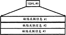
The data structure of having represented TDFL in the accompanying drawing 6 of patent documentation 1.
Comprise defective related information (information regarding defect) #1, #2 etc. among the TDFL.
The defective related information comprises status information (state information), point to the pointer of defect cluster, point to the pointer that replaces bunch.
The defective related information have with said SDL in the same data structure of the SDL item that comprises and bring into play same function.
Figure 33 A and Figure 33 B represent the update method of the accompanying drawing 9A and the disclosed TDFL of accompanying drawing 9B of patent documentation 1.
Figure 33 A representes the data structure of TDFL#0.TDFL# 0 comprises and defective # 1, #2, the corresponding defective related information of #3 #1, #2, #3.
After supposing that TDFL# 0 is write down, in additional record type CD, carried out new data recording, defective # 4, #5 have taken place.At this moment, the TDFL# 1 shown in Figure 33 B is recorded on the additional record type CD.
Here, TDFL# 1 generates through the defect management information that comprises among the TDFL# 0 all being kept and newly append with defective # 4, the corresponding defective related information of #5 #4, #5.
The data structure of having represented the defective related information in the accompanying drawing 10 of patent documentation 1.
The defective related information comprises status information.Status information comprises and is used for representing that defect area is the continuous defect piece (continuous defect block) or the information of independent defect block (single defectblock).
And then the defective related information comprises the pointer (position of defect area on disc) that points to defect area.
And then the defective related information comprises the pointer that points to the corresponding replacement of defect area district.
When defect area was continuous defect block sequence, the pointer that status information representes to point to defect area was beginning of continuous defect piece or end position.In addition, also beginning or end positions that the pointer that replaces the district is these replacement pieces are pointed in expression.
Through utilizing these data structures in additional record type CD, to realize mechanisms of defect management.
And then, when using said mechanisms of defect management to be, also can in additional record type CD, realize covering (pseudo-overwrite) record of simulation.
The simulation of using Figure 31 and Figure 32 explanation in additional record type information recording carrier, to carry out covers record.
In said mechanisms of defect management; By means of defective related information or the such replacement information of SDL item, can not change on data recording apparent logical address and with the physical address map (mapping) of physical record data to keeping other positions of getting up in advance.
Therefore; On additional record type CD, there has been the logical addresses covering to write data if send indication; As long as then with in the sector of this data recording to other physical address and upgrade replacement information to keep original logical address, just can be from the apparent state of realizing data are override record.Later on this recording method is called simulation and overrides record.
Figure 31 is the figure that has write down the state behind several catalogues and the file in the information recording carrier 1 that is illustrated in as additional record type CD.In addition, under this state, simulate as yet and override record.
In additional record type CD, be the user data area on the unit management disc with optical track and section.
Among Figure 31, the management of the user data that writes down in the user data area realizes by means of file system.The space that file system is managed is called volume space 2.
In addition; In following explanation; Short of write up especially is as the volume/file structure of configuration file system and be recorded in descriptor or structure of pointer, metadata (meta data) subregion or meta data file in the information recording carrier 1 etc. and all have ISO/IEC13346 standard or UDF (Universal Disk Format: the universal disc format) data structure of prescribed by standard.
Among Figure 31, volume structure district 3 and Physical Extents 4 have been write down in the volume space 2.
The metadata partition 5a, the 5b that comprise UDF Standard Edition 2.5 defineds in the Physical Extents 4.
In addition, write down meta data file 6a and in the Physical Extents 4 as the metadata image file 6b of its copy.
In addition, the file item (FE) of representing the record position in these Physical Extents 4 is that FE (meta data file) 7a and FE (metadata image file) 7b also go on record.In addition, data file (File-a) 8, data file (File-b) 9 have also been write down.
It is in the meta data file that document structure information such as FE or catalogue file all is configured in metadata partition.
In the data structure of UDF prescribed by standard, in volume structure district 3, write down the record position of metadata partition 5a and set of file descriptor (FSD) 12.
As the starting point of FSD12, can begin retrieving files structure successively from the ROOT catalogue, for example visit data file (File-a) 8.
Then, when new simulation overrides data file (File-c) under the state at Figure 31, just become state shown in Figure 32.
Here, tentation data file (File-c) is recorded under the ROOT catalogue on the information recording carrier 1.
When recording data files (File-c), upgrade and the required document structure information of generation data, supplemental file (File-c).Specifically be the renewal of FE (ROOT) 13 and the generation of FE (File-c) 14.
In addition, data file (File-c) 15 is recorded the not recording areas of Figure 31, becomes the state of Figure 32.
When FE (File-c) 14 went on record, FE (File-c) 14 was recorded the not recording areas 11a among the metadata partition 5a (being meta data file 6a).
Then, FE (ROOT) 16 is override by simulation and records on the FE (ROOT) 13.
At this moment, shown in figure 32, the data of FE (ROOT) 16 are recorded replacement district 17.
And then, upgrade the replacement information that comprises in the disc management information 2, FE (ROOT) 13 is mapped to FE (ROOT) 16.
After having carried out such file logging processing, the action of playback of data file (File-c) 15 becomes as follows.
Obtain the positional information of FE (meta data file) 7a and FSD12 from the volume structure district 3 of information recording carrier 1.
Then, carry out the regeneration of file structure.For the file structure of regenerating,, carry out the regeneration of FSD12 based on the positional information of acquired FE (meta data file) 7a and FSD12.
From regeneration FSD12 obtain FE (ROOT) 13 positional information as logical address.
Based on the positional information (logical address) of the FE that is obtained (ROOT) 13, carry out the regeneration of FE (ROOT) 13.
At this moment, with reference to replacement information, regeneration is mapped to the FE (ROOT) 16 of the positional information (logical address) of FE (ROOT) 13.
FE (ROOT) 16 comprises up-to-date ROOT catalogue file, thereby has the positional information of sensing FE (File-c) 14.
In addition, utilize the positional information of the data file (File-c) 15 that obtains from FE (File-c) 14, playback of data file (File-c) 15.
In aforesaid additional record type CD, also can simulate and override record by means of mechanisms of defect management.
Patent documentation 1: U.S. Patent application discloses instructions No. 2004/0076096
But the simulation of said illustrated additional record type CD overrides the problem that exists in the recording mode and is: in case the not recording areas in the replacement district runs out, even still have not recording areas in the user data area, also can't proceed data recording.Reason is, can't the updating file system information.
Particularly, additional record type CD is different from the erasable type CD that replacement district capacity can be expanded when needed, and it is just definite when disc formatsization (initialization).
In addition, very difficult consideration is simulated and is override record and definite in advance suitable replacement district capacity.
If pre-determined replacement district capacity is excessive, then the user data area capacity reduces, even the too small situation that then can occur still having in the user data area recording areas not also can't continue record data.Which kind of situation no matter all can not effectively utilize the user data area of additional record type CD.
Summary of the invention
The invention solves said problem, its purpose is to provide a kind of simulation at additional record type CD to override the drive unit that can not utilize user data area in the record lavishly.
Drive unit of the present invention is a kind of drive unit that additional record type recording medium is carried out order (sequential) record; Wherein, Said additional record type recording medium comprises data field and disc management information area, and the data field comprises replacement district and user data area, the disc management information that record is used for managing said additional record type recording medium in said disc management information area; A plurality of physical addresss are distributed in said data field; Said user data area is distributed a plurality of logical addresses, said user data area is distributed at least one optical track, said disc management information comprises the optical track management information that is used for managing said at least one optical track; Said optical track management information comprises the final entry address; This final entry address is the physical address of the position of last record data in the expression optical track, and said drive unit comprises: record regenerating portion, carry out operation of recording or regeneration action to said additional record type recording medium; And drive control part, control said record regenerating portion, wherein, the performed processing of said drive control part comprises: read said disc management information from said disc management information area; Based on said disc management information, confirm the basic logical address-physical address map of the corresponding relation of the said a plurality of logical addresses of expression and said a plurality of physical addresss; The receiving record indication, this record indication comprises the logical address that the position of record data is answered in expression; According to said basic logical address-physical address map, the said logical address that comprises in the said record indication is transformed to physical address; Based on the corresponding said physical address of said logical address and the said optical track management information that comprise in indicating with said record, confirm an optical track in said at least one optical track; Based on the said final entry address in the said determined optical track, but the physical address of the position of next recorded data in the said determined optical track of expression is confirmed as recording address next time; But to the indication of said record in the corresponding said physical address of said logical address that comprises and said next time recording address compare; But when with the indication of said record in the corresponding said physical address of said logical address that comprises less than said next time during recording address; Performed processing comprises: control said record regenerating portion and make the ad-hoc location of said data recording in the said user data area, this ad-hoc location be by with said record indication in ad-hoc location beyond the position shown in the corresponding said physical address of said logical address that comprises; Generate new disc management information; This information comprises alternative management information and by the said final entry address after the said data recording renewal, the corresponding said physical address map of said logical address that this alternative management information will comprise in will indicating with said record is to the physical address of the said ad-hoc location of expression; And control said record regenerating portion and make said new disc management information is recorded in the said disc management information area; When with the indication of said record in the corresponding said physical address of said logical address that comprises when said next time, but recording address equated, performed processing comprises: control said record regenerating portion feasible with said data recording to by the position shown in the corresponding said physical address of said logical address that comprises in indicating with said record; Generate new disc management information, this information comprises by the said final entry address after the said data recording renewal; And control said record regenerating portion and make said new disc management information is recorded in the said disc management information area.
Also can be that said additional record type recording medium comprises a plurality of ECC bunches; Said a plurality of ECC bunch comprises a plurality of sectors respectively; Said a plurality of sectors are distributed said a plurality of physical address respectively; Said next time, but recording address was the physical address that comprises the beginning sector that comprises in next ECC of ECC bunch bunch of said final entry address.
Also can be, said definite optical track be open optical track, but the ad-hoc location in the said user data area is confirmed as by the represented position of recording address next time in the said determined optical track.
Also can be; Said definite optical track is open optical track; But the ad-hoc location in the said user data area is confirmed as by the represented position of recording address next time in the optical track different with said determined optical track; But said next time of the recording address in the said open optical track representes near the position by the position shown in the said physical address, and this physical address is corresponding with the said logical address that comprises during said record is indicated.
Drive unit of the present invention is a kind of drive unit that data recorded in the additional record type recording medium is regenerated; Wherein, Said additional record type recording medium comprises data field and disc management information area; The data field comprises replacement district and user data area; The disc management information that record is used for managing said additional record type recording medium in said disc management information area is distributed a plurality of physical addresss to said data field, and said user data area is distributed a plurality of logical addresses; Said disc management information comprises the alternative management information tabulation that contains a plurality of alternative management information; Said a plurality of alternative management information will be represented the physical address map of the position in the said user data area respectively to other physical address, and said drive unit comprises: record regenerating portion, carry out operation of recording or regeneration action to said additional record type recording medium; And drive control part, control said record regenerating portion, wherein, the performed processing of said drive control part comprises: read said disc management information from said disc management information area; Based on said disc management information, confirm the basic logical address-physical address map of the corresponding relation of the said a plurality of logical addresses of expression and said a plurality of physical addresss; Receive the regeneration indication, this regeneration indication comprises the logical address that the position of playback of data is answered in expression; According to said basic logical address-physical address map, the said logical address that comprises in the said regeneration indication is transformed to physical address; Use the tabulation of said alternative management information, determine whether be with said regeneration indication in the corresponding physical address of said logical address that comprises be not mapped as the replacement source position of other physical addresss but be mapped as the replacement destination locations of other physical addresss; When confirm as with said regeneration indication in the corresponding physical address of said logical address that comprises be not mapped as the replacement source position of other physical addresss but when being mapped as the replacement destination locations of other physical addresss; Playback of data in the corresponding physical address of said logical address that from indicate, does not comprise, but output predetermined data with said regeneration.
Also can be that said predetermined data is the data of regenerating in the corresponding physical address of said logical address that from indicate with said regeneration, comprises.
By means of the present invention, can provide a kind of simulation to override the drive unit that can not utilize user data area in the record lavishly at additional record type CD.
Description of drawings
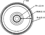
Figure 1A is the figure of an instance of the outward appearance of information recording carrier 100 in the expression embodiment of the present invention.
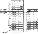
Figure 1B is the figure of an instance of the data structure of information recording carrier 100 in the expression embodiment of the present invention.
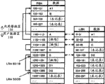
Fig. 1 C is the figure of an instance of the data structure of the user data area 108 of expression shown in Figure 1B.
Fig. 2 A is the figure of an instance of the data structure of section management information 200 in the expression embodiment of the present invention.
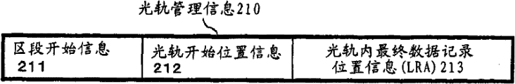
Fig. 2 B is the figure of an instance of the data structure of optical track management information 210 in the expression embodiment of the present invention.
Fig. 2 C is the figure of an instance of the data structure of free area management information 220 in the expression embodiment of the present invention.
Fig. 3 is the figure of an instance of the data structure of disc structure information 1100 in the expression embodiment of the present invention.
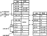
Fig. 4 is the figure of an instance of the data structure of another information recording carrier 100b in the expression embodiment of the present invention.
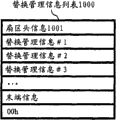
Fig. 5 A is the figure of an instance of the data structure of alternative management information tabulation 1000 in the expression embodiment of the present invention.
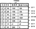
Fig. 5 B is the figure of an instance of the data structure of alternative management information 1010 in the expression embodiment of the present invention.
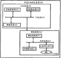
Fig. 6 is the block diagram of an instance of the structure of information recording/reproducing apparatus 300 in the expression embodiment of the present invention.
Fig. 7 is the figure of an instance of the data structure on the information recording carrier after format is handled in the expression embodiment of the present invention.
Fig. 8 A is the process flow diagram of recording processing in the expression embodiment of the present invention.
Fig. 8 B is the process flow diagram that RMW handles in the expression embodiment of the present invention.
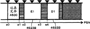
Fig. 9 is the figure of an instance of the data structure on the information recording carrier after the recording processing in the expression embodiment of the present invention.
Figure 10 is the process flow diagram of the Regeneration Treatment in the expression embodiment of the present invention.
Figure 11 is the figure of an instance of the data structure of alternative management information 1010B in the expression embodiment of the present invention.
Figure 12 is the figure of an instance of the data structure of physical address space and logical address space in the expression embodiment of the present invention.
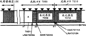
Figure 13 A is the key diagram about replacement record in the embodiment of the present invention.
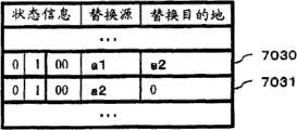
Figure 13 B is the key diagram about alternative management information in the embodiment of the present invention.
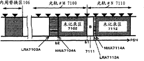
Figure 14 A is the key diagram about replacement record in the embodiment of the present invention.
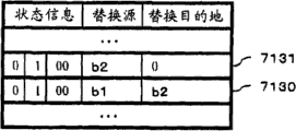
Figure 14 B is the key diagram about alternative management information in the embodiment of the present invention.
Figure 15 A is the key diagram about replacement record in the embodiment of the present invention.
Figure 15 B is the key diagram about alternative management information in the embodiment of the present invention.
Figure 16 A is the key diagram about replacement record in the embodiment of the present invention.
Figure 16 B is the key diagram about alternative management information in the embodiment of the present invention.
Figure 17 A is the key diagram about replacement record in the embodiment of the present invention.
Figure 17 B is the key diagram about alternative management information in the embodiment of the present invention.
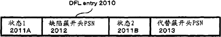
Figure 18 is that alternative management information is the figure of an instance of the data structure of DFL entry2010 in the expression embodiment of the present invention.
Figure 19 A is the process flow diagram of the recording processing in the expression embodiment of the present invention.
Figure 19 B is the process flow diagram of the recording processing in the expression embodiment of the present invention.
Figure 20 A is the key diagram about replacement record in the embodiment of the present invention.
Figure 20 B is the key diagram about alternative management information in the embodiment of the present invention.
Figure 21 A is the key diagram about replacement record in the embodiment of the present invention.
Figure 21 B is the key diagram about alternative management information in the embodiment of the present invention.
Figure 22 A is the key diagram about replacement record in the embodiment of the present invention.
Figure 22 B is the key diagram about alternative management information in the embodiment of the present invention.
Figure 23 A is the key diagram about replacement record in the embodiment of the present invention.
Figure 23 B is the key diagram about alternative management information in the embodiment of the present invention.
Figure 24 A is the key diagram about replacement record in the embodiment of the present invention.
Figure 24 B is the key diagram about alternative management information in the embodiment of the present invention.
Figure 25 is the exemplary plot of the data structure of optical track management information in the embodiment of the present invention.
Figure 26 A is the key diagram about replacement record in the embodiment of the present invention.
Figure 26 B is the key diagram about alternative management information in the embodiment of the present invention.
Figure 27 is the key diagram about replacement record in the embodiment of the present invention.
Figure 28 is the key diagram about replacement record in the embodiment of the present invention.
Figure 29 is the key diagram about replacement record in the embodiment of the present invention.
Figure 30 is the key diagram about replacement record in the embodiment of the present invention.
Figure 31 is the figure of an instance of the data structure on the information recording carrier in the expression prior art.
Figure 32 is the figure of an instance of the data structure on the information recording carrier after the expression prior art file recording processing.
Figure 33 A is the figure of an instance of the data structure of TDFL in the expression prior art.
Figure 33 B is the figure of an instance of the data structure of TDFL in the expression prior art.
Figure 34 is the figure of an instance of the data structure of disc structure information 1100 in the expression embodiment of the present invention.
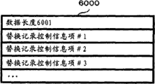
Figure 35 A is the figure of an instance of the data structure of replacement record controls information list in the expression embodiment of the present invention.
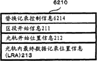
Figure 35 B is the figure of an instance of the data structure of optical track management information 210 in the expression embodiment of the present invention.
Figure 36 A is the key diagram about replacement record in the embodiment of the present invention.
Figure 37 A is the key diagram about replacement record in the embodiment of the present invention.
Figure 37 B is the key diagram about alternative management information in the embodiment of the present invention.
Figure 38 A is the key diagram about replacement record in the embodiment of the present invention.
Figure 39 A is the key diagram about replacement record in the embodiment of the present invention.
Figure 39 B is the key diagram about alternative management information in the embodiment of the present invention.
Figure 40 is the exemplary plot of the data structure of optical track management information in the embodiment of the present invention.
Figure 41 A is the key diagram about replacement record in the embodiment of the present invention.
Figure 42 A is the key diagram about replacement record in the embodiment of the present invention.
Figure 42 B is the key diagram about alternative management information in the embodiment of the present invention.
Figure 43 is the exemplary plot of the data structure of optical track management information in the embodiment of the present invention.
Figure 44 is the exemplary plot of the data structure of optical track management information in the embodiment of the present invention.
Symbol description
100,100b information recording carrier
101 Lead-In Areas
102,102a data field
103 leading-out zones
103b, 103c perimeter region
104,104a, 105,105a disc management information area
106, the week replacement is distinguished in the 106a
107,107a periphery replacement district
108,108a user area
109 volume spaces
122 recording areas not
120、121LRA
210 optical track management information
211 section start informations
212 optical track start position informations
Final data record position information (LRA) in 213 optical tracks
300 information recording/reproducing apparatus
301 systems control divisions
302 memory circuitries
The 303I/O bus
304 disk sets
310 drive units
311 drive control parts
312 memory circuitries
313 internal buss
314 record regenerating portions
410 volume structure districts
420 Physical Extents
440 meta data files
450 metadata image files
The tabulation of 1000 alternative management information
1010,1010B alternative management information
1011 status informations
1012 replacement source location information
1013 replacement destination locations information
1100 disc structure information
1103 user data area start position informations
1104 user data area end position information
1105 replacement district information
2010DFL?entry
2012 defect clusters beginning PSN
2013 replace a bunch beginning PSN
Embodiment
Below, on one side with reference to accompanying drawing, embodiment of the present invention is described on one side.
(the 1st embodiment)
1-1. additional record type recording medium
Figure 1A representes the outward appearance of the information recording carrier 100 of embodiment of the present invention.
Required reference information or with the identifying information of other recording mediums etc. when having write down the optical pickup apparatus visit information recording medium 100 that in the record regenerating portion 314 of back literary composition narration, comprises in the Lead-In Area 101.In the leading-out zone 103 also the record with Lead-In Area 101 in the identical information of institute's information recorded.
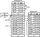
For Lead-In Area 101, data field 102 and leading-out zone 103 have distributed a plurality of physical sectors.Each physical sector is minimum one access unit.Each physical sector is discerned through the such address information of physical sector number (being called PSN later on).
ECC bunch (or the ECC piece) that will comprise a plurality of physical sectors carries out data recording and regeneration as least unit.
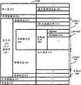
Figure 1B representes the data structure of information recording carrier 100.Among Figure 1B, the Lead-In Area that is expressed as concentric circles among Figure 1A 101, data field 102 and leading-out zone 103 are represented with landscape configuration.
Lead-In Area 101 comprises disc management information area 104, and leading-out zone 103 comprises disc management information area 105.
Difference record disc management information in the disc management information area 104,105.Disc management information is included in the civilian alternative management information tabulation of narrating in back, section management information, free area management information etc.Disc management information area 104,105 is used as needed zone when upgrading disc management information.The required zone of this renewal is also referred to as interim disc management information area.
In addition; When applying the present invention to the BD-R standard; Term in this instructions " disc management information area " is interpreted as " disc directorial area "; Term in this instructions " interim disc management information area " is interpreted as " interim disc directorial area ", and the term in this instructions " disc management information " is interpreted as " disc management structure ", and the term in this instructions " interim disc management information " is interpreted as " interim disc management structure ".
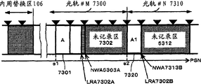
In comprising, data field 102 replaces district 106, user data area 108 and periphery replacement district 107 week.
Fig. 1 C representes the data structure of user data area 108.
Each optical track is the continuum on the information recording carrier 100.Each optical track is managed through the optical track management information of the literary composition narration in the back.
In addition, when applying the present invention to the BD-R standard, the term in this instructions " optical track " is interpreted as " journal district (SRR) ".
Each section comprises many optical tracks that dispose continuously on the information recording carrier 100.Each session is managed through the section management information of the literary composition narration in the back.
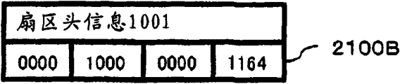
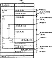
Fig. 2 A representes to be used for to manage the data structure of the section management information 200 of section.Section management information 200 is included in the disc management information.
Section management information 200 comprises sector head (header) information 201 and a plurality of optical track management information.
Sector head information 201 has the general information such as number of the optical track management information of representing among identifier or Fig. 2 B of section management information 200 210.
Optical track management information #N has and the optical track #N information corresponding shown in Fig. 1 C.Here, N is the integer more than or equal to 1.
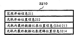
Fig. 2 B representes to be used for to manage the data structure of the optical track management information 210 of optical track.Optical track management information 210 is included in the disc management information.
Optical track management information 210 comprises: section start information 211 is used for representing whether optical track is the beginning optical track of section; Optical track start position information 212 is used for representing the starting position of optical track; And final data record position information (being called LRA later on) 213 in the optical track, be used for representing the interior position of record data at last of optical track.
If the optical track that certain bar optical track management information 210 is managed is positioned at the beginning of section, represent that then the value (for example " 1 ") that this optical track is arranged in section beginning is set to section start information 211.In addition, in section start information 211, set different values (for example " 0 ").
Optical track start position information 212 comprises the physical address of the starting position of representing optical track.
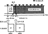
Final data record position information 213 comprises the physical address that is used for representing having write down in the optical track final position of valid data in the optical track.Valid data are meant the user data that for example provides from host apparatus 305.LRA120 shown in Fig. 1 C or LRA121 are instances of final data record position information 213 in the optical track.
In addition, when applying the present invention to the BD-R standard, the term in this instructions " optical track management information " is interpreted as " journal district item ", and the term in this instructions " section management information " is interpreted as " journal district information ".
In addition, information recording carrier 100 with ECC bunch be least unit when carrying out data recording, final data record position information 213 is not limited to indicate ECC bunch border in the optical track.This is because generally speaking, the data capacity of record indication defined can not be the integral multiple of ECC bunch capacity.At this moment, LRA213 representes to write down the last physical sector address that the data of indication defined are write down.
In addition, when LRA213 and ECC bunch of border were inconsistent, the data recording padding data of record indication defined and then was up to ECC bunch of border.
In this embodiment, can be by the optical track record data.New data recording is carried out from each optical track beginning, and in optical track, data are by configuration (journal) continuously.In this optical track, carry out data recording, the position of last record is reflected in the interior final data record position information 213 of optical track in this optical track.
When in this optical track, writing down once more,, just can know next record starting position in this optical track through checking the value of final data record position information 213 in the up-to-date optical track.
In addition, when after having distributed optical track, and then in this optical track, not having data recording fully, also can in optical track, set the setting (for example " 0 ") of this state of expression in the final data record position information 213.
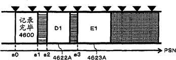
But next record position (being called NWA later on) expression is by the position of the next physical sector of the physical sector shown in the final data record position information 213 in the optical track.Perhaps, when information recording carrier 100 is a least unit when carrying out data recording with certain ECC bunch, NWA representes to comprise by next ECC bunch the beginning position physical sector shown in the final data record position information 213 in the optical track, ECC bunch.
If represent, be (formula 1) with formula.
(formula 1)
(a) LRA ≠ 0 o'clock,
NWA=N×(Floor(LRA/N)+1)
The physical sector number that comprises in N:ECC bunch (for example, N=32)
(b) during LRA=0
NWA=(starting position of corresponding optical track)
Wherein, Floor (x) expression is smaller or equal to the max-int of x.
In the explanation afterwards, suppose that NWA representes ECC bunch beginning position.
The optical track that is in the state of recorded data is called open optical track (open track).
The track number of open optical track is included in (for example, the 1st open track number the 203, the 2nd is opened track number 204 etc.) in the sector head information 201 in the section management information 200 shown in Fig. 2 A.
On the other hand, the optical track of non-open optical track is called sealing optical track (closed track).
For example, there is not the optical track of recording areas not or become the sealing optical track by the optical track of user's indication.
Different with open optical track, the track number of sealing optical track is not kept in the sector head information 210 in the section management information 200.
Forbid record data in the sealing optical track.
Through checking final data record position information 213 in the optical track in open track number and the optical track management information 210, just can know the not recording areas on the information recording carrier 100.
In addition, when applying the present invention to the BD-R standard, open optical track is represented open SRR.In addition, the sealing optical track representes to seal SRR.
In addition, in additional record type information recording carrier 100, also can finish through management accounts ECC bunch, thus the optional position on information recording carrier (physical address) record data are promptly realized a kind of recorded at random.
In order to realize this recorded at random, must manage free area on the information recording carrier 100 and final data record position.
In this embodiment, utilize the disc management information of record in free area management information 220 shown in Fig. 2 C and the disc management information area 104,105, realize this management.
When carrying out recorded at random, the free area management information 220 in the disc management information area 104 shown in the record diagram 2C.
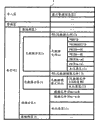
Fig. 2 C representes the data structure of free area information 220.Free area information 220 comprises sector head information 221, management object district information 222 and free area information 223.
Sector head information 221 has the general information such as identifier of free area management information 220.
Management object district information 222 comprises and is used for specifying especially the information in the zone in the user data area 108, and this user data area 108 comprises the sector that state manages that finishes of record/record not.For example, management object district information 222 comprises this regional starting position or length that should the zone.
Free area information 223 comprises each ECC bunch of being used for representing comprising in the management object zone and does not write down or write down the information that finishes.For example, to each ECC bunch of data of distributing each 1 bit, if corresponding ECC bunch of record then be set at for example " 0 " as yet if record finishes then is set at for example " 1 ", thus, can be realized the management of whole ECC bunches idle condition of target area.
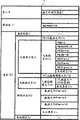
The disc management information of record comprises disc structure information 1100 shown in Figure 3 in the disc management information area 104.Disc structure information 1100 comprises final data record position information 1107.Final data record position information 1107 comprises the physical address that has write down the position of data in the expression user data area 108 at last.
Through using disc management information area information 1107b, can be to the capacity of each information recording carrier change disc management information area.And then, through using disc management information area information 1107b, replace the capacity of interim disc management information area described in district 106 or the periphery replacement district 107 in can changing week.
Through using replacement district information 1105, can be to the capacity in each information recording carrier change replacement district.For example, also can capacity that replace district 106 or periphery replacement district 107 interior week be appointed as 0.
Replacement district management information 1108 comprises the next available position information of next available position in all replacements district 106 in the expression, the periphery replacement district 107.
In each replacement district, likewise carry out journal with optical track.Next available position information performance during each replacement is distinguished and the NWA identical functions in the optical track, the new data records that the replacement district is done begins from the position shown in the next available position information to carry out in proper order.
As stated, use the idle condition of any physical sector on can management information recording medium 100 in section management information 200 or the free area management information 220.Thus, also can select use some in section management information 200 or the free area management information 220 according to purposes.Perhaps, also can use both simultaneously.This packets of information relevant with the free area way to manage is contained in the record kind of information 1106 of disc structure information 1100.
In addition; Disc management information area 105 for the reliability that improves information recording carrier 100 to disc management information area 104 in the disc management information of record when carrying out duplicated record or upgrading disc management information etc.; Be used expansion area under the situation under in disc management information area 104, preserving not, therefore omit its detailed description later on.In addition, for processing too such as the medium interim disc management information that writes down in replacement district.
In the instance shown in Fig. 1 C, the management of the user data of record is carried out by means of file system on the user data area 108.The space that file system is managed is called volume space 109.
Volume space a plurality of logic sectors have been distributed.Each logic sector is discerned through the such address information of logical sector number (being called LSN later on).
In addition; In following explanation; Short of write up especially is as the volume/file structure of configuration file system and the descriptor or pointer, metadata partition or the meta data file etc. that are recorded in the information recording carrier 100 all have ISO/IEC13346 standard or UDF (UniversalDisk Format: the universal disc format) data structure of prescribed by standard.Certainly, also can use other file system.
In addition, though the information recording carrier 100 shown in Figure 1A~Fig. 1 C is to describe as the medium with 1 recording layer, also can be information recording carrier with 2 above recording layers.
Fig. 4 representes to have the data structure of the information recording carrier 100b of 2 recording layers.
In Fig. 4, L0 representes the 1st layer, and L1 representes the 2nd layer.Layers 1 and 2 has the structure roughly the same with information recording carrier 100 respectively.That is, Lead-In Area 101 be arranged on the 1st layer in all sides, leading-out zone 103a be arranged on the 2nd layer in week.And then, be provided with perimeter region 103b at the 1st layer most peripheral, be provided with perimeter region 103c at the 2nd layer most peripheral.Lead-In Area 101, perimeter region 103b, leading-out zone 104a, perimeter region 103c comprise disc management information area 104,105,104a, 105a respectively.
In addition, as shown in Figure 4, be provided with replacement district 106,106a, 107,107a.As stated, the capacity in each replacement district can be made change to each information recording carrier.In addition, in each replacement district the interim disc management information area that appends can be set also.In addition, user data area 108 is taken as 1 volume space processing in logic with continuous logical address with 108a.
As stated, can the information recording carrier with a plurality of recording layers be used as the information recording carrier that logically has 1 recording layer handles.After, though describe to the information recording carrier with 1 recording layer, these explanations also are applicable to the information recording carrier with a plurality of recording layers.Therefore, the information recording carrier with a plurality of recording layers only suitably is described under the situation that needs specify.
1-2. simulation overrides record
Below, with reference to Fig. 5 A and Fig. 5 B explanation replacement information.
Replacement information refers to the alternative management information tabulation (perhaps defect list) that comprises alternative management information (perhaps defect list entry), and replacement source location information and the expression that this alternative management information comprises the position of bunch (defect cluster) that occurred defective on the expression information recording carrier is used for replacing the replacement destination locations information of position of the replacement bunch of this defect cluster.
In addition, among the present invention, can in user data area, write down and replace bunch.
And then the present invention utilizes replacement information to realize that the simulation in additional record type information recording carrier covers record.
Shown in Figure 1B, in comprising, data field 102 replaces district 106, user data area 108 and periphery replacement district 107 week.
In in week replacement district 106 and the periphery replacement district 107 at least a portion be used as the zone that data recorded on the user data area 108 is replaced record.
For example, when having defect cluster on the user data area 108, at least a portion is used as required replacement bunch replaced in record to this defect cluster zone in interior week replacement district 106 and the periphery replacement district 107.
Perhaps, at least a portion also can be used as the simulation of stating behind the record and overrides the required zone of data after upgrading in the record in interior week replacement district 106 and the periphery replacement district 107.
Replacement information is implemented with checking treatment with the replacement record that the replacement district combines.
Checking treatment is meant after record data these data of regenerating, and the data of recorded data and regeneration are compared, and checks whether data are correctly noted at once.A series of processing like this are called write-verify checking and handle.
When checking treatment is made mistakes, when promptly data are not correctly noted, implement the replacement record.That is, defect cluster is replaced by and replaces bunch, during data are recorded and replace bunch.
The week replacement was distinguished in 106 (or periphery replacement districts 107) or the user data area 108 in this replacement bunch quilt recorded.
Simulation cover record be a kind of do not change on data recording apparent logical address and with the physical address map of physical record data method to other place.
When sending indication when having had the logical addresses covering to write data; With override before the different other physical address of the physical address of data recording on ECC bunch in the new data of record, and before will overriding ECC bunch bunch map with the replacement of having write down new data.
The replacement bunch quilt that this simulation covers in the record records in replacement district or the user data area.
Use the alternative management information tabulation 1000 shown in Fig. 5 A as carrying out the required replacement information of this mapping.
By means of such mapping treatment,, can realize the state that data are capped though in fact data are not capped with simulating.Later on this recording method is called simulation and overrides record.
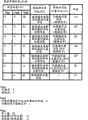
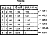
Fig. 5 A representes the data structure as the alternative management information tabulation 1000 of replacement information of the present invention.The mapping of the position that alternative management information tabulation 1000 is used to carry out defect cluster and the position that replaces bunch.Alternative management information tabulation 1000 comprises sector head information 1001, a plurality of alternative management information 1010 (alternative management information # 1, #2, #3......).
Sector head information 1001 comprises the number of the alternative management information that comprises in the alternative management information tabulation 1000.Alternative management information comprises the information of representing said mapping.
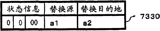
Fig. 5 B representes the data structure of alternative management information 1010.Alternative management information 1010 comprises status information 1011, replacement source location information 1012 and replacement destination locations information 1013.
Status information 1011 comprises the status information relevant with said mapping.For example, represent the kind of alternative management information 1010 or effective/disarmed state of attribute, replacement source location information 1012 and replacement destination locations information 1013 etc.
The position of the information (for example defect cluster) in replacement source location information 1012 expression replacement sources.
The position of the information of replacement destination locations information 1013 expression replacement destinations (for example replace bunch).
In addition, override in simulation under the situation of record, ECC bunch position before covering with 1012 indications of replacement source location information to replace ECC bunch position after 1013 indications of destination locations information cover, is shone upon thus.
Here, the replacement source location information 1012 of login also can use the physical address (for example PSN) of corresponding ECC bunch beginning sector to represent with replacement destination locations information 1013 in the alternative management information 1010.This is because it is that unit shines upon that defect management overrides in the record with ECC bunch with simulation.
In existing linear orthomorphism, replace bunch being recorded in the replacement district.Thus, there is ECC bunch positional information in the replacement district to be set in wherein in the replacement destination locations information 1013 always.
On the other hand, in the present invention, replace bunch being not limited to be recorded in the replacement district, also can be recorded in user data area.Therefore, can set the information of ECC bunch position in the expression replacement district in the replacement destination locations information 1013, perhaps set the information of ECC bunch position in the expression user data area.
In addition; Replacement destination locations information 1013 has become any one the ECC that is write down bunch that can indicate in two zones; Therefore; Also can in status information 1011, discriminant information be set, what be used for differentiating 1013 indications of replacement destination locations information is ECC bunch in the replacement district ECC bunch or the user data area.
1-3. record regenerator
Fig. 6 representes the structure of the information recording/reproducing apparatus 300 of embodiment of the present invention.
Information recording/reproducing apparatus 300 comprises host apparatus 305 and drive unit 310.
Drive unit 310 can be pen recorder, regenerating unit, record regenerator any one.In addition, also can information recording/reproducing apparatus 300 integral body be called pen recorder, regenerating unit, record regenerator.
Systems control division 301 is realized by means of the control program of for example system or the microprocessor that comprises operand store.The record regenerating of the volume structure/file structure of 301 pairs of file system of systems control division, the record regenerating in the civilian metadata partition/file structure narrated in back, the record regenerating of file, the processing such as record regenerating of importing/leading-out zone are controlled and computing.
Drive unit 310 comprises drive control part 311 and memory circuitry 312, record regenerating portion 314.Textural element in the drive unit 310 interconnects through internal bus 313.
Drive control part 311 is realized by means of the control program of for example driver or the microprocessor that comprises operand store.The record regenerating in 311 pairs of disc management information areas of drive control part or replacement district, simulation override processing such as record regenerating and control and computing.
In addition, systems control division 301 shown in Figure 6 or drive control part 311 both can be realized by means of SIC (semiconductor integrated circuit) such as LSI, also can realize by means of general processor and storer (for example ROM).
Preserve the executable program of computing machine (for example general processor) in the storer (for example ROM).Regeneration Treatment of the present invention and the recording processing stated after this program representation is addressed, computing machine (for example general processor) is carried out Regeneration Treatment of the present invention and recording processing according to this program.
Memory circuitry 312 is used for operation of data that the relevant data in disc management information area or replacement district and drive unit 310 send and interim preservation etc.
1-4. recording processing step (1)
Then, explain that with reference to Fig. 7 carrying out format in this embodiment handles the data structure on the information recording carrier 100 afterwards.
The metadata partition 430 that comprises UDF Standard Edition 2.5 or version defined thereafter in the Physical Extents 420.
Write down meta data file 440 in the Physical Extents 420.In addition, in the explanation afterwards, be the relevant explanation of metadata image file though omitted for simplicity with the copy of meta data file 440, can certainly write down the metadata image file.
In addition, the file item (FE) that has write down the record position in the Physical Extents 420 of representation element data file 440 is FE (meta data file) 441.
Document structure informations such as the record position of expression subscriber data file and the FE of capacity, catalogue file all are configured in metadata partition 430, are in the meta data file 440.
Only write down the ROOT catalogue among Fig. 7, therefore, in meta data file 440, only write down set of file descriptor (FSD) 433 and FE (ROOT) 442.In addition, for the purpose of simplifying the description, take it is included in the form among each FE for catalogue file.
In addition, suppose that this is the state that does not carry out any replacement record as yet constantly.In addition, the free area management in the metadata partition 430 also can be carried out according to metadata bitmap (not shown), so that stipulate by UDF Standard Edition 2.5.
Perhaps, also can the free area of metadata partition 430 be kept Unrecorded state, utilize the LRA405 of optical track # 1 that the free area in the metadata partition 430 is managed.
In addition, the distribution method of optical track is not limited to shown in Figure 7, for example, also can distribute more optical track.In addition, also can the optical track at the end of user data area be changed to the state that can append new optical track, append optical track in case of necessity.
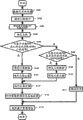
Then, with reference to the step of data recording among the flowchart text the present invention shown in Fig. 8 A.
Here, tentation data file (File-a) is recorded in the information recording carrier 100.
In addition, the user data area 108 of information recording carrier 100 has been distributed a plurality of logical addresses and a plurality of physical address, supposed that these a plurality of logical addresses and the corresponding relation of these a plurality of physical addresss are predetermined.
Each of these a plurality of logical addresses is for example all passed through logical sector number (LSN) or LBA (LBA) is represented.
Each of these a plurality of physical addresss is then represented through for example physical sector number (PSN) or physical block address (PBA).In addition, suppose user data area 108 distribution at least one optical track.
Before the record of data file (File-a), drive control part 311 is carried out the preparation of data recording and is handled (step S101).The preparation of this data recording is handled when for example information recording carrier 100 is packed drive unit 310 into and is carried out.
For example, drive control part 311 is read up-to-date disc management information from the disc management information area 104 (or disc management information area 105) of information recording carrier 100.
According to this disc management information; Confirm to be used for to represent the basic logical address-physical address map of the corresponding relation of a plurality of logical addresses that user data area 108 is distributed and a plurality of physical addresss; For this reason, obtain user data area start position information 1103, user data area end position information 1104, the replacement district information 1105 etc. of Fig. 3.
After, drive control part 311 carries out the conversion of logical address and initial physical addresses according to basic logical address-physical address map.
In addition, drive control part 311 is obtained the optical track management information that comprises in the disc management information.
(step S102) drive control part 311 is indicated from host apparatus 305 receiving records.Record indication comprises the logical address that is used for representing answering the position of record data.This logical address is represented through for example logical sector number (LSN) or LBA (LBA).Record indication both can comprise the unity logic address that is used for representing writing down the position of single data, also can comprise a plurality of logical addresses that are used for representing writing down respectively a plurality of positions of a plurality of data.
The logical address that comprises in the record indication is confirmed based on the logical address (being logic NWA) that for example is used for representing next position that can record data in the specific optical track by host apparatus 305.
Logic NWA is for example corresponding to send to the request of drive unit 310 from host apparatus 305, outputs to host apparatus 305 from drive unit 310.
Logic NWA obtains through carrying out conversion according to basic logical address-physical address map by said (formula 1) determined NWA.This conversion is carried out by drive control part 311.Definite step of NWA and logic NWA after specify in the 2nd embodiment stated.
The filesystem information that the systems control division 301 of host apparatus 305 generates when recording data files (File-a) and renewal needs.For example, in memory circuitry 302, to generate the parent directory with the corresponding FE of data file (File-a) (File-a), updated data file (File-a) be the ROOT catalogue to systems control division 301.
Generate like this with the corresponding FE of data file (File-a) (File-a) or the ROOT catalogue after upgrading through from host apparatus 305 to drive unit 310 output records indication and recorded information recording carrier 100, reflect up-to-date filesystem information.
In addition, whether host apparatus 305 uses the order of regulation to remain to drive unit 310 inquiries where necessary and replaces the required not recording areas of record.
In addition, the indication that outputs to drive unit 310 from host apparatus 305 also can be the standardized commands of SCSI multimedia order etc.
For example, the request of logic NWA or record indication also can be respectively READ TRACKINFORMATION order or WRITE order.
The logical address that the record that (step S103) drive control part 311 will receive in step S102 according to basic logical address-physical address map comprises in indicating is transformed to physical address.
The optical track management information 210 (Fig. 2 B) that comprises in corresponding physical address of logical address that (step S104) drive control part 311 bases comprise in indicating with this record and the disc management information, the optical track (open optical track) at least one optical track of confirming user data area 108 is distributed.
Drive control part 311 confirms to be used for being illustrated in the physical address (being NWA) of the position of next recorded data in this determined optical track based on the LRA213 of this determined optical track.This NWA be for example according to said (formula 1) but determined next time recording address.
In addition, the definite of NWA both can carry out in step S104, also can in other steps, carry out.For example, also can, the preparation of said data recording accomplish in advance in handling.
Here, use LRA213 to calculate NWA, the data structure of optical track management information is become simple, and need in optical track management information, not preserve NWA information.
Whether the corresponding physical address of logical address that (step S105) drive control part 311 comprises in confirming to indicate with this record is littler than NWA.
If confirm as with the indication of this record in the corresponding physical address of logical address that comprises littler than NWA, then should record indication being confirmed as is that the record that writes down the zone that finishes that is directed against in the user data area 108 is indicated.That is, to be confirmed as be that simulation covers record to the data recording of record indication.In this case, handle entering step S106.Otherwise, handle getting into step S 108.
(step S106) drive control part 311 confirms to answer data recorded.Under the data recording unit in the information recording carrier 100 is ECC bunch situation, drive control part 311 will be confirmed as by the specified data of record indication and answer data recorded.For example, when the record position of the specified data of record indication was consistent with ECC bunch border with capacity, ECC bunch of integral body was rewritten, and therefore, will be confirmed as by the specified data former state of record indication and answer data recorded.
Under inconsistent situation, " read, change, write " of stating after drive control part 311 is carried out handles.In this case, the data of the drive control part 311 ECC bunch of unit that will in " read, change, write " processing procedure, obtain are confirmed as and are answered data recorded.
(step S107) drive control part 311 is confirmed by the determined record position of answering record data of step S106.Particularly; Drive control part 311 will be the ad-hoc location in the user data area 108 by the ad-hoc location beyond the position shown in the corresponding physical address of logical address that comprises in indicating with this record, confirm as the determined record position of answering record data by step S106.
Here, this ad-hoc location also can be the NWA in the determined optical track in step S104.
Perhaps, this ad-hoc location also can be the NWA in the open optical track different with determined optical track in step S104.In this case, the NWA in this opening optical track preferably representes and writes down nearest position, position shown in the corresponding physical address of logical address that comprises in the indication.
Whether the corresponding physical address of logical address that (step S108) drive control part 311 comprises in confirming to indicate with this record equals NWA.If confirm as with the indication of this record in the corresponding physical address of logical address that comprises equal NWA, then should record indication being confirmed as is that the record that is directed against position shown in the NWA is indicated.That is, to be confirmed as be to append (new record) to the data recording of record indication.In this case, handle entering step S109.Otherwise, handle getting into step S111.
(step S109) drive control part 311 confirms to answer data recorded.Particularly, drive control part 311 will write down the specified data of indication and confirm as and answer data recorded.
At this moment, whether drive control part 311 is judged by the end of the specified data of record indication consistent with ECC bunch of border.If inconsistent, then insert padding data (for example all being the data of 00h), the end that makes data with after ECC bunch of border is consistent as answering data recorded.
(step S110) drive control part 311 is confirmed by the determined record position of answering record data of step S109.Particularly, drive control part 311 will be confirmed as the determined record position of answering record data by step S109 by the position (promptly by the position shown in the NWA) shown in the corresponding physical address of logical address that comprises in indicating with this record.
(step S111) drive control part 311 carries out fault processing.
311 pairs of determined record position executive loggings of (step S112) drive control part are handled.
Under the situation that is judged to be " being " of step S105, drive control part 311 controlling recording regeneration portions 314 make the data recorded of answering that will in step S106, confirm record determined record position in step S107.
Under the situation that is judged to be " being " of step S108, drive control part 311 controlling recording regeneration portions 314 make the data recorded of answering that will in step S109, confirm record determined record position in step S110.
And then the data behind 311 pairs of records of drive control part are carried out checking treatment, confirm thus whether this data recording is successful.If this data recording success handles then getting into step S113.
If the failure of this data recording, in then distributing week district such as replacement such as 106 grades, replacement district and any zone of user data area 108 in not recording areas instead bunch, during this data recording replaced bunch to this.
If final this data recording success handles then getting into step S113.
In addition, the processing of said step S106 and step S112 also can realize by means of " read, change, write " processing (being called RMW later on handles).
In RMW handles; The 1st; Drive control part 311 controlling recording regeneration portions 314 make regeneration comprise data recorded in ECC bunch of physical sector; And the data that will from this ECC bunch, regenerate are saved in memory circuitry 312 (" reading " handle), and this physical sector is arranged in by the position shown in the corresponding physical address of logical address that comprises with the record indication.
In addition, when carrying out this Regeneration Treatment, ECC bunch of the regeneration object might be replaced record.Therefore, drive control part 311 controlling recording regeneration portions 314 make with reference to alternative management information tabulation 1000 and data recorded in ECC bunch of regeneration replacement destination as required.The literary composition narration is with reference to the data reproduction step of alternative management information tabulation 1000 in the back.
The 2nd; Drive control part 311 will be from this ECC bunch of born again data, be recorded in by with the record indication in data in the physical sector of the position shown in the corresponding physical address of logical address that comprises, be replaced into by record indication data designated (" changing " handles).Consequently, ECC bunch data after the renewal have been obtained.
Drive control part 311 is implemented " reading " and is handled and " changing " processing in step S106.
Fig. 8 B is illustrated in and carries out the step of being implemented when " reading " handles with " changing " processing among the step S106 shown in Fig. 8 A.Each step shown in Fig. 8 B is carried out by the drive control part 311 of drive unit 310.
Whether ECC bunch of confirming to comprise by the specified position of record indication of (step S151) drive control part 311 is replaced bunch replacement.Thisly confirm to realize through for example retrieving alternative management information tabulation 1000.
Replaced bunch replacement when having found when being the alternative management information 1010 in replacement source, just having confirmed as, handled getting into step S152A by the specified position of record indication.Otherwise, handle getting into step S152B.
In addition, also can the result of determination of step S151 be preserved as the value of built-in variable, confirm to comprise by record with reference to this built-in variable value in other steps in case of necessity and indicate ECC bunch of specified position whether to be replaced bunch replacement.Thus, can avoid repeating same processing.For example, if the result of determination of step S151 is " being ", then preserve " 1 " value as this built-in variable; If the result of determination of step S151 is " denying ", then preserve " 0 " value as this built-in variable.
(step S152A) drive control part 311 need to determine whether RMW to handle.For example, when by the position of the specified data of record indication when consistent with ECC bunch border with size, drive control part 311 is definite not to need the RMW processing; When the position of being indicated specified data by record and size and ECC bunch border were inconsistent, drive control part 311 is confirmed as needed RMW to handle.
When confirming as when needing RMW to handle, handle getting into step S153; Otherwise, handle getting into step S157.
Also can likewise the result of determination of step S152A be preserved as the value of built-in variable, need determine whether RMW to handle in other steps with reference to this built-in variable value in case of necessity with step S151.
(step S152B) drive control part 311 need to determine whether RMW to handle.The processing of step S152B is identical with the processing of step S152A.
When confirming as when needing RMW to handle, handle getting into step S154; Otherwise, handle getting into step S157.
(step S153) drive control part 311 controlling recording regeneration portions 314 make regeneration in the replacement shown in the alternative management information 1010 that step S151 finds bunch rather than comprise data recorded in ECC bunch by the specified position of record indication, and the data of regeneration are saved in memory circuitry 312.
(step S154) drive control part 311 controlling recording regeneration portions 314 make regeneration comprise data recorded in ECC bunch by the specified position of record indication, and the data of regeneration are saved in memory circuitry 312.
(step S155) drive control part 311 is served as reasons the data replacement of regeneration and is write down the specified data of indication, generates revised data thus.
(step S156) drive control part 311 is confirmed as the data that should record in the information recording carrier 100 with revised data.
(step S157) drive control part 311 will be confirmed as the data that should record in the information recording carrier 100 by the specified data of record indication.
So far, finishing " reading " handles and " changing " processing.
The 3rd, drive control part 311 controlling recording regeneration portions 314 make ECC bunch data recording after the renewals that will in " changing " handles, obtain to original ECC bunch position (" writing " processing).Drive control part 311 is implemented " writing " and is handled in step S112.
But, in the present invention, because information recording carrier is to append the type medium, therefore in fact can't be at original ECC bunch location records.
Therefore, in distributing week district such as replacement such as 106 grades, replacement district and any zone of user data area 108 in not recording areas instead bunch, during the data recording after upgrading replaced bunch to this.
And then the data behind 311 pairs of records of drive control part are carried out checking treatment, confirm thus whether this data recording is successful.If this data recording success handles then getting into step S113.
If the failure of this data recording, in then distributing week district such as replacement such as 106 grades, replacement district and any zone of user data area 108 in not recording areas as further replacing bunch, during this data recording further replaced bunch to this.
After final this data recording success, handle getting into step S113.
In addition, when, all can being rewritten for ECC bunch when whole corresponding to ECC bunch, therefore, no longer need described " reading " to handle by the specified zone of record indication.
(step S113) drive control part 311 generates alternative management information 1010 according to the processing among the step S112, and this alternative management information is saved in memory circuitry 312.For example; In step S112; When drive control part 311 controlling recording regeneration portions 314 make after being record data in the ad-hoc location in the user data area 108 (implement to simulate and override) by the ad-hoc location beyond the position shown in the corresponding physical address of logical address that comprises in indicating with this record; Drive control part 311 generates alternative management information 1010, and the corresponding physical address map of logical address that this information will comprise in will indicating with this record is to the physical address of this ad-hoc location of expression.
In addition, also can be through retrieving the alternative management information 1010 that existing alternative management information tabulation 1000 determines whether in existing alternative management information tabulation 1000, to have found to have the replacement source location information 1012 identical with the pairing physical address of logical address that comprises during record is indicated.
If found, 311 of drive control parts upgrade this alternative management information 1010, are set at new replacement destination locations information 1013 so that will represent the physical address of this ad-hoc location.
If do not find, 311 of drive control parts generate new alternative management information 1010 and should new alternative management information 1010 be appended in the alternative management information tabulation 1000.
Then, drive control part 311 is carried out the rearrangement of alternative management information tabulation 1000.For example, drive control part 311 also can be arranged alternative management information tabulation 1000 according to status information 1011 again, then the physical address of replacement source location information 1012 is carried out the arrangement again of alternative management information tabulation 1000.
So just generated new alternative management information tabulation 1000, the corresponding physical address map of logical address that the alternative management information 1010 that wherein comprises will comprise in will indicating with record is to the physical address that is used for representing this ad-hoc location.
(step S114) drive control part 311 upgrades disc management information to reflect said operation of recording.For example, drive control part 311 upgrades final data record position information 1107.In addition, drive control part 311 upgrade with the corresponding optical track management information 210 of optical track that has write down data in LRA213 to reflect up-to-date recording status.
And then drive control part 311 generates the new disc management information that has comprised the information after new alternative management information tabulation 1000 is upgraded with optical track management information 210 grades.In addition; Set the alternative management information list placement information 1102 and section management information positional information 1109 that comprise in the new disc management information, to represent new alternative management information tabulation 1000 or the state-of-the-art record position of optical track management information 210 on information recording carrier 100.
Drive control part 311 controlling recording regeneration portions 314 are so that record the regulation zone (for example interim disc management information area) on the information recording carrier 100 with new disc management information.According to this kind mode, disc management information is updated to last state.
In addition, after data recording finished, drive unit 310 also can be given host apparatus 305 with the result notification of said operation of recording.The result of operation of recording is meant and representes the for example information of data recording success or data recording failure etc.
This notice can send to host apparatus 305 at numerical time.For example, can be when step S108 finishes, or in step S112, this notice is sent to host apparatus 305 during wrong generation.Perhaps also can before the data recording physical end, this notice be sent to host apparatus 305.For example, can receive the record indication from host apparatus 305 and can will represent that the notice of end of record (EOR) sends to host apparatus 305 in this record indication of correct understanding at drive unit 310.
In addition, in said replacement recording processing, also can begin to become big direction from ECC bunch the position in replacement source and retrieve not recording areas to PSN.After recording areas has been found not in retrieval like this, with this not recording areas distribute instead bunch.
In addition, also can be earlier in comprising the optical track in replacement source bunch, retrieve not recording areas, begin to become big direction from this optical track then and retrieve the not recording areas each bar optical track successively to PSN.
If the retrieval of the recording areas end that arrived user data area 108 is not still found not recording areas, can be to retrieve not recording areas in the periphery replacement district 107 then in the zone of this user data area 108 and then.
And then; If the retrieval of recording areas has not arrived the end of replacing district 107 and has not still found not recording areas; Then can begin to become big direction and retrieve not recording areas from the assigned position of interior all sides of information recording carrier 100 (for example, the beginning of the beginning in interior week replacement district 106, user data area 108, or apart from the position of these beginning predetermined distances) to PSN.
In addition, in the step S105 and step S108 of data recording step,, confirm this digital simulation is override record or additional record through comparing with the corresponding physical address of logical address and the NWA that are comprised by the record indication.
Why can confirm this digital simulation is override record or additional record through such comparison process; Be because information recording carrier 100 is additional record type information recording carriers; And, can carry out journal to this additional record type information recording carrier.
The replacement record that the use user data area of describing among the present invention is realized also can be applied to erasable type CD.But, under the situation of erasable type CD, override record or additional record (or new record) in order to confirm this data recording, need more complex processing step.Reason is that under the situation of erasable optical disk, the arbitrary site on the CD can rewrite at random.
If that kind is implemented the free area management by drive unit to erasable type CD shown in said embodiment; Then as described in the explanation of background technology, for example need use SDL to ECC bunch of whole on the erasable type CD management of carrying out corresponding alternative management information.And, in order to confirm that the data recording that do in certain place in the user data area on certain erasable type CD is override record or new record, need for example retrieve whole alternative management information tabulation 1000 and finish to judge whether to write down.Likewise, whether be used as and replaced bunch in order to understand fully certain ECC bunch, also must the whole alternative management information tabulation 1000 of retrieval.The treatment capacity of this processing can increase and increase along with alternative management information 1000 the capacity of tabulating, and the CD that constantly increases, can become serious problem for capacity.
On the other hand, in the present invention,, can guarantee that in certain bar optical track address value all is to have write down the zone that finishes less than the zone of NWA because of it is additional record type information recording carrier and is journal.
Thus, just can confirm that simply this data recording is that simulation overrides record or additional record, and not receive the influence of the capacity of alternative management information tabulation 1000 by means of step S105 and 108 such comparison process.In addition, replace bunch get final product, therefore be easy to selection from the later choice of location of NWA.
In addition, simulate with the recorded at random mode of additional record type CD and override when record also the situation with erasable type CD is identical.
And then, under the situation of the recorded at random mode of additional record type CD, need the special structure of described free area management information 220 and so on.Compare with the free area management of journal mode, the free area management information 220 of recorded at random mode has increased the processing load of drive control part 311 significantly.
Particularly, in the journal mode, can be with the numerical limitations of opening optical track (for example maximum 4) in the scope of the convenience that does not damage file system.
At this moment, the number of open optical track depends on the structure of file system, can not receive the influence that CD capacity increases; On the other hand, the capacity of the free area management information 220 of recorded at random increases along with the increase of CD capacity, handles load and also increases.
That is, for the CD that capacity constantly increases, the effect highly significant of the present invention that uses the journal mode to simulate the mode of overriding.
In addition, the invention is characterized in,, confirm NWA with (formula 1) according to the LRA213 that comprises in the up-to-date optical track management information 210 in order to confirm to use simulation to override record or additional record.
Through on disc, writing down the LRA213 that upgrades by data recording in advance, information recording carrier 100 is packed into behind the drive unit 310, find the required time of up-to-date LRA213 to shorten.
In addition, calculate NWA, just can construct the optical track management information data simply, and need in optical track management information, not preserve NWA information through using LRA213.
If do not use the present invention,, just need for example following steps in order to confirm to use simulation to override record or additional record.
That is, must confirm to comprise and the optical track that writes down the corresponding physical address of logical address that comprises in the indication, check ECC bunch in proper order, judge whether that record finishes from the beginning beginning of this optical track.
Then, if ECC bunch of the position of record indication write down and finished, then confirm as simulation and override record.
This processing especially becomes its treatment capacity of big back at the optical track capacity and also becomes very big, and is therefore inadvisable.
On the other hand, if use this embodiment, then can not receive the influence of optical track capacity and confirm simply the simulation override the record still be additional record.
In addition, through in optical track management information 210, comprising LRA213, just can when driver 10 receives the record indication, confirm the optical track of record destination, and confirm NWA at an easy rate.
Fig. 9 representes to utilize this recording step to write down the data structure of the information recording carrier 100 after the data file.
Explanation is as the data file (File-a) 460 of an instance of data file among Fig. 9.Suppose and use said recording step in data file (File-a) 460, to detect defect cluster # 1 and defect cluster # 2.
For this reason, suppose that disc management information is recorded in the disc management information area 104, this disc management information comprises and is used for representing to replace bunch alternative management information of #1 replacement defect cluster # 1 to represent to replace bunch alternative management information of #2 replacement defect cluster # 2 with being used for.
As shown in Figure 9, replace a bunch # 1 to be recorded in replacement district 106, replace a bunch # 3 to be recorded in user data area 108.
And then (data file File-a) 460 its content after this record is accomplished overrides record through simulation and upgrades.
Particularly, upgrade bunch # 2 and upgrade the part that bunch # 4 partly is equivalent to override by simulation the record renewal.
Suppose that being override the new data that writes down renewal by simulation is recorded respectively among the replacement bunch # 2 and replacement bunch # 4 that distributes as the replacement of upgrading bunch # 2 and renewal bunch # 4, corresponding replacement information is recorded in the disc management information area 104.
As shown in Figure 9, replace a bunch # 2 to distribute to replacement district 106, replace a bunch # 4 to distribute to user data area 108.
1-5. Regeneration Treatment step (1)
Regeneration Treatment with reference to the flowchart text file of Figure 10.Here, the action with the data file shown in Figure 9 (File-a) 460 of regenerating is that example describes.
Before the playback of data file, drive control part 311 is carried out the preparation of data reproduction and is handled (step S201).The preparation of this data reproduction is handled when for example information recording carrier 100 is packed drive unit 310 into and is carried out.For example, drive control part 311 is read disc management information from the disc management information area 104 (or disc management information area 105) of information recording carrier 100.
Drive control part 311 is obtained user data area start position information 1103, user data area end position information 1104, replacement district information 1105 etc. from this disc management information, in order to the basic logical address-physical address map of the corresponding relation of a plurality of logical addresses of confirming to be used for to represent user data area 108 is distributed and a plurality of physical addresss.
After, drive control part 311 is according to basic logical address-physical address map, the conversion of actuating logic address and initial physical addresses.
(step S202) at first, systems control division 301 sends regeneration indication to drive unit 310, the AVDP of record in the assigned position of regenerating information recording medium 100 (for example LSN=256).
In addition, AVDP by the UDF standard code, become the data structure of the starting point of filesystem information, be recorded in volume structure district 410 and the volume structure district 411.
(step S203) follows, and systems control division 301 is obtained the positional information of the Primary Volume Descriptor string 410A of record in the volume structure district 410 from AVDP.Systems control division 301 further sends indication to drive unit 310, regeneration master file structure 410A.
Systems control division 301 further begins to call over data structure from the Primary Volume Descriptor string 410A of regeneration, obtains the positional information (LSN) of FE (meta data file) 441.
(step S204) follows, the regeneration of systems control division 301 execute file structures.For the file structure of regenerating, systems control division 301 according to the positional information (LSN) of the FE that is obtained (meta data file) 441 to drive unit 310 indication of regenerating, regeneration FE (meta data file) 441.
Here, systems control division 301 obtains the positional information of meta data file 440 among the information of the FE (meta data file) 441 that obtained, thereby can accesses meta-data file 440.
After (step S205), according to the regeneration step of common UDF standard, with the order of FSD433, FE (ROOT) 442, FE (File-a) 443, data file (File-a) 460 regenerate (omitting explanation) to the regeneration of catalogue file.
In each step of described Regeneration Treatment, indicate to drive unit 310 output regeneration from host apparatus 305.The drive control part 311 of drive unit 310 receives the regeneration indication from host apparatus 305, carries out Regeneration Treatment according to this regeneration indication.
Regeneration indication comprises the logical address that is used for representing answering the position of playback of data.Logical address is represented through for example logical sector number (LSN).Perhaps, logical address also can be represented through LBA (LBA).In addition, regeneration indication is a read command for example.
Drive control part 311 will be regenerated according to basic logical address-physical address map (for example with reference to Figure 12), and the logical address that comprises is transformed to physical address in the indication.
Then; Drive control part 311 determines whether in alternative management information tabulation 1000, to have found alternative management information 1010 through retrieval alternative management information tabulation 1000, and this alternative management information 1010 has and the identical replacement source location information 1012 of the pairing physical address of logical address that comprises during regeneration is indicated.
If found, 311 controlling recording regeneration of drive control part portion 314 makes its replacement destination locations information 1013 with reference to this alternative management information 1010, begins playback of data from the position shown in this replacement destination locations information 1013.
If do not find, 311 controlling recording regeneration of drive control part portion 314, the position playback of data shown in the feasible corresponding physical address of logical address that from indicate, comprises with regeneration.The data of regenerating according to this kind mode are returned to host apparatus 305.
1-6. recording processing step (2)
Figure 11 representes the data structure of alternative management information 1010B.The different embodiments of the alternative management information 1010 shown in the alternative management information 1010B presentation graphs 5B.
Comprise following 3 information among the alternative management information 1010B of Figure 11 as status information 1011.Shown in figure 11, these 3 information notes are Flag1, Flag2, Flag3.
Flag1 is used for information that alternative management information 1010B is classified, comprises to be used for representing that this replacement information is used to replace record or to be used for indicating defect cluster.
Flag3 be with alternative management information 1010B managed bunch the relevant information of number, comprise be used for representing this replacement information be with single bunch corresponding or with a plurality of bunches of continuous information corresponding.When with continuous a plurality of bunches of corresponding situation under, Flag3 further comprise be used for representing corresponding with the starting position of continuum or with the end position information corresponding.
After, according to Figure 11 detailed recording step of the present invention is described.
In addition, use the kind of the symbolic representation alternative management information of Figure 11 right-hand member row later on where necessary.For example, the alternative management information note that the 1st row is had a such status information 1011 of Flag1=1 (replacement with), Flag2=0 (being substituted into the replacement district), Flag3=00 (single bunch) is done alternative management information (1).
Figure 12 is the exemplary plot of the data structure of physical address space and logical address space on the information recording carrier 100 of the present invention.
In addition, Figure 12 also represented when host apparatus 305 is observed, to be illustrated in the position on the information recording carrier 100 logical address logical sector number (LSN), with the corresponding relation of physical address physical sector number (PSN) under original state that is illustrated in the physical location on the information recording carrier 100.This corresponding relation is called basic logical address-physical address map (representing with the wave-like line arrow among the figure, down together).
1 row shown in Figure 12 is corresponding to 1 ECC bunch.In Figure 12, physical address (PSN) is illustrated in in the delegation with the logical address (LSN) that is assigned to this physical address.
In Figure 12, the value representation of PSN and LSN is the PSN and the LSN value of the terminal sector that begins from corresponding ECC bunch beginning sector.
Here, though be example, also can be other structures with 1 ECC bunch situation about constituting by 32 sectors.
In being assigned to, replaces PSN district 106, periphery replacement district 107 and user data area 108 week.
In addition, suppose from the beginning of user data area 108 and begin to distribute optical track.Since record data not fully under the state of Figure 12, therefore, the beginning of LRA500 directed towards user data field 108.
On the other hand, LSN only is assigned to user data area 108 (perhaps volume space 109).
The particular logical sector that host apparatus 305 uses on this LSN appointed information recording medium 100 writes down and the indication of regenerating.
Drive unit 310 will be transformed to PSN according to basic logical address-physical address map from the LSN that host apparatus 305 receives, again according to the PSN of gained visit physical sector or ECC bunch.
In the replacement record of explanation, be the basis afterwards, when needs and this corresponding relation different logical address-physical address map, then use alternative management information 1010 with basic logical address-physical address map.
In addition, PSN among Figure 12 and the value of LSN only are used to the instance explained, and actual value is different and different with the structure of information recording medium 100 and capacity.
In addition, as stated, though the capacity in disc management information and replacement district is variable, their capacity is being confirmed according to formaing when handling from the indication of host apparatus 305 etc.In addition, after format was handled, the beginning and the end position of user data area 108 no longer changed.
Basic logical address-physical address map can be confirmed according to the computing of the information of the disc structure information 1100 that comprises in the disc management information (user data area start position information 1103, user data area end position information 1104, replacement district information 1105 etc. in more detail) through regulation etc. uniquely.
Use-case with reference to Figure 12~Figure 17 B explanation alternative management information 1010B shown in Figure 11.
At first, variation from the state of Figure 12 to the state of Figure 13 A is described.
The drive unit 310 that receives the indication of this record is transformed to PSN=1100 according to basic logical address-physical address map with LSN=0, in the location records data " A " of PSN=1100.
Then, 310 pairs of data recorded of drive unit are carried out verification.Here suppose verification succeeds.
And then host apparatus 305 is emitted in the position of LSN=0 and simulates the indication that overrides record data " A1 ".
The drive unit 310 that receives the indication of this record is transformed to PSN=1100 according to basic logical address-physical address map with LSN=0, carries out RMW in the position of PSN=1100 and handles.Then, the location records data " A1 " of PSN=100 in replacement district 106.
At this moment, generate alternative management information 511 by drive unit 310.The record position of setting data " A " is PSN=1100 in the replacement source of alternative management information 511, and the record position of setting data " A1 " is PSN=100 in the replacement destination of alternative management information 511.The status information 1011 of alternative management information 511 is set according to Figure 11.
In addition, alternative management information 511 is corresponding to the solid arrow among Figure 13 A.The starting point of arrow is represented the replacement source, and the terminal point of arrow representes to replace destination (later identical).
And then in Figure 13 A, host apparatus 305 indications are in the location records data " B " of LSN=2.
Verification failure when record data " B ", data " B " can be by the position that week is replaced the PSN=132 in the district 106 in recording.
The replacement record correspondingly generates alternative management information 512 therewith.Set PSN=1032 in the replacement source of alternative management information 512, set PSN=132 in the replacement destination of alternative management information 512.The status information 1011 of alternative management information 512 is set according to Figure 11 similarly.
Data configuration behind the said record and alternative management information tabulation are shown in Figure 13 A and Figure 13 B.Used alternative management information (1) among the alternative management information tabulation 1000A of Figure 13 B.
On the other hand, Figure 14 A and Figure 14 B are the figure that is used for explaining the state when having used alternative management information (4), (7).
Here, host apparatus 305 indications are in the location records data " C " of LSN=64.Drive unit 310 records data " C " according to this record indication the position of PSN=1164.Here, if the result of verification makes mistakes, then the not recording areas (PSN=1196) in the distributing user data field 108 is replaced data " C " position that records PSN=1196.
According to this result, generate alternative management information 513.
And then host apparatus 305 indications thereafter, are indicated record data " D1 " in the location records data " D " of LSN=128.
In addition, if the failure of the verification behind the record data " D1 ", data " D1 " then are replaced the position that records PSN=1292.
At this moment, generate alternative management information 514.
In addition, PSN=1260 is a defect cluster of not replacing the destination, generates corresponding alternative management information 515.
And then host apparatus 305 indications are when the simulation of the position of LSN=128 overrides record data " D2 ", and data " D2 " are replaced the position that records PSN=1324.
At this moment, generate alternative management information 514A.On the other hand, because alternative management information 514 no longer needs, therefore it is deleted from alternative management information tabulation 1000.
After above recording processing, LRA is updated to the position of 500B.
In addition, the alternative management information 1000B (Figure 14 B) that tabulates is arranged the Flag1 in the status information 1011 again, then the PSN value of replacement source location information 1012 is arranged again.
Figure 15 A and Figure 15 B are the figure that is used for explaining the state when having used alternative management information (5), (6).
Here, host apparatus 305 indications are in the location records data " E " of LSN=256~X1.
At this moment, if verification failure, data " E " are replaced the position that records PSN=x2~x3, then generate alternative management information 516 and alternative management information 517.These two alternative management information represent respectively to be equivalent to replace record the starting position ECC bunch beginning PSN and be equivalent to ECC bunch beginning PSN of end position.
Suppose that in Figure 16 A and Figure 16 B host apparatus 305 further indication overrides record data " E1 " in the simulation of the position of LSN=257~X1.
At this moment, to be recorded among the 15A be the position of the PSN=x4~x5 of recording areas not to data " E1 ".
In addition, generate the information of alternative management information 516A, generate the information of alternative management information 517A as the end point of this replacement record of expression as the starting point of this replacement of expression.
At this moment, owing to no longer need alternative management information 516,517, therefore, with its deletion from the alternative management information tabulation.
In addition, though in Figure 15 A and 16A, replacement record destination all is positioned at user data area 108, can certainly be positioned at replacement district 106.In this case, use alternative management information (2), (3).
In addition, as illustrated with reference to Fig. 8 A, the alternative management information list records after the renewal is in the disc management information area.
1-7. Regeneration Treatment step (2)
When regeneration accordings to this kind mode data recorded, the processing below needing to carry out.
Before playback of data, drive control part 311 is carried out the preparation of data reproduction and is handled.The preparation of this data reproduction is handled identical with for example described step S201.
Then, under the state of for example Figure 13 A, suppose the indication of data " B " of sending regeneration LSN=32 from host apparatus 305,310 of drive units are obtained PSN=1132 according to basic logical address-physical address map.
So drive unit 310 alternative management information that retrieval has PSN=1132 from up-to-date alternative management information tabulation 1000 is as the replacement source.
Here, find alternative management information 512, therefore, obtain the PSN=132 of replacement destination from here.
Drive unit 310 is from PSN=132 playback of data " B ", sends it back host apparatus 305 as the playback of data of LSN=32.
Even host apparatus 305 specified LSN have changed, the processing of drive unit 310 1 sides is still identical.The LSN that receives is transformed to PSN according to basic logical address-physical address map, if found corresponding alternative management information, playback of data from replace bunch then.If can not find corresponding alternative management information, then get final product according to the regeneration of PSN former state.
As above, override in the record in the simulation of information recording carrier 100, just can be lavishly with user data area as the replacement destination.
1-8. recording processing step (3)
Figure 18 representes that the different structure instance with the same alternative management information of said alternative management information 1010 or alternative management information 1010B is DFL entry2010.
Here, and with reference to illustrated identical of Fig. 5 B, defect cluster beginning PSN 2012 with replace a bunch beginning PSN 2013 also can use the physical address (for example PSN) of corresponding ECC bunch beginning sector to represent.This is because it is that unit shines upon that defect management overrides in the record with ECC bunch with simulation.
Here, state 1 2011A comprise at least with alternative management information 1010B in the Flag1 information identical with Flag2.That is, for example, when the value of state 1 2011A is under the situation of " 1000 ", its replacement information representes not replace destination (Flag2==0 is equivalent to not replace the situation of destination).In this case, in replacing bunch beginning PSN 2013, set " 0 ".
On the other hand, when having the replacement destination, in state 1, set " 0000 " (Flag2=0 is equivalent to have the situation of replacement destination).
In addition, state 2 2011B comprise at least with alternative management information 1010B in the identical information of Flag3.
That is, for example, when the value of state 2 2011B is under the situation of " 0000 ", this replacement information is corresponding to single bunch (being equivalent to Flag3=00).
Likewise, when the value of state 2 is for example under the situation of " 0001 ", this replacement information is corresponding to the beginning sector position (being equivalent to Flag3=01) of beginning bunch that comprises a plurality of bunches continuum.On the other hand, under the situation of " 0010 ", corresponding to the beginning sector position (being equivalent to Flag3=10) at end bunch that comprises a plurality of bunches continuum.
This DFL entry2010 goes for whole embodiments.
Secondly, with reference to the data structure of DFL entry2010 shown in Figure 180 and the process flow diagram of Figure 19 A, the instance that further explain is handled to the alternative management information of using among the illustrated step S113 of said Fig. 8 A.
Here, suppose that the step S112 at Fig. 8 A gets into step S113 for realizing that simulation overrides after record writes down the replacement destination.
(step S301) at first judge this simulation override record be override for the 1st time record or the 2nd time or after this override record.
This judgement is to carry out as the DFL entry2010 of defect cluster beginning PSN2012 value through for example up-to-date alternative management information list retrieval being had beginning PSN value that in the step S103 of Fig. 8 A, obtain, ECC bunch, and this ECC bunch comprises the corresponding physical address of logical address that comprises in indicating with record.
This up-to-date alternative management information tabulation is born again from the disc management information area in for example step S101 (Fig. 8 A), and is saved in memory circuitry 312.
If in the alternative management information tabulation, do not find corresponding alternative management information (for example DFL entry2010), then override record as the 1st simulation, handle getting into step S302.
If in the alternative management information tabulation, found corresponding alternative management information, then override record as the 2nd simulation, handle getting into step S304.
In addition, also can in other steps, prejudge simulation override record be override for the 1st time record or the 2nd time or after this override record.For example, also can judge at step S106.Can preserve the judged result of this moment, use at step S301.
(step S302) is if following the processing then carried out in the 1st replacement record.
At first, on the memory circuitry 312 of drive unit 310, generate new DFL entry2010 by drive control part 311.
(step S303) then sets numerical value in this DFL entry2010.
That is, set suitable value for state 1 2011A.For example, if there is the replacement record of replacement destination, then set " 0000 ".
Then, defect cluster beginning PSN2012 is set ECC bunch the beginning PSN value that is arranged in the corresponding physical address of logical address that comprises with the record indication.
Then, to the beginning PSN value of replacement bunch of data that replaced physical record in the replacement record of bunch beginning PSN2013 before being set in.
And then, to the suitable value of state 2 2011B setting of this DFL entry2010.For example, if single bunch replacement record is then set " 0000 ".
(step S304) is if following the processing then carried out in the 2nd later replacement record.
That is,, get into step S305 for the DFL entry2010 that in step before, finds is carried out update processing.
(step S305) at first is updated to appropriate value with state 1 2011A of this DFL entry2010.For example, if there is the replacement record of replacement destination, then set " 0000 ".
Then, with replace bunch beginning PSN2013 be updated to before the replacement record in physical record the beginning PSN value of replacement bunch of data.That is, set new replacement destination.
In addition, because be the 2nd later replacement record,, keep identical value to get final product so need not change defect cluster beginning PSN2012 to identical ECC bunch.
And then, state 2 2011B of this DFL entry2010 are updated to appropriate value.For example, if single bunch replacement record is then set " 0000 ".
(step S306) realizes the renewal of alternative management information tabulation through above processing.That is, append new DFL entry2010, perhaps upgrade existing DFL entry2010 value.
In addition, tabulation is arranged again to alternative management information.This is arranged again for example state 1 2011A is carried out.And then, arrange again according to the order of defect cluster beginning PSN2012, state 2 2011B, replacement bunch beginning PSN2013.
Thus, the step S113 of Fig. 8 A finishes.Here the up-to-date alternative management information tabulation of gained is arrived (temporarily) disc management information area by additional record.
In addition, though in described processing instance, the replacement record that to override record and carry out in order to realize simulating has been described, the occasion of the replacement of carrying out when this is equally applicable to defect cluster occur record.
Yet, as in the background technology with reference to Figure 33 A and Figure 33 B illustrated, in the defect management of existing additional record type CD, all keep existing alternative management information and append new alternative management information when the replacement record occurring at every turn.
If this method is applied to the such recording method that user data area is used as the replacement destination of this embodiment; Alternative management information will increase when each appearance replacement was write down; It is big that the capacity of alternative management information tabulation becomes, so be not suitable for the installation of drive unit etc.
Particularly, in the defect management of existing additional record type CD, what once be replaced bunch can not be replaced once more, but overrides under the situation of record in this simulation of this embodiment, possibly repeatedly become the object of replacement record.For this reason, the capacity of alternative management information tabulation possibly become very big.
In addition, a plurality of alternative management information with value of same defect bunch beginning PSN2012 can appear in alternative management information tabulation, this just further need the processing of appending with machine-processed to obtain up-to-date alternative management information.
In addition, in the defect management of erasable type CD, to whole replacements destination alternative management information bunch is set, no matter whether it has been used as the replacement destination.
If this method is applied to such user data area is used as in the method for replacement destination of this embodiment, just need just to have begun a large amount of alternative management information, inadvisable equally.
On the other hand, by means of the method for using Figure 19 A, only generate needed MIN defect management information and manage and get final product, up-to-date alternative management information also is easy to find.
1-9. recording processing step (4)
Processing instance with reference to the alternative management information in Figure 19 B further explain data recording step.
Each step shown in Figure 19 B is included among the step S113 shown in Fig. 8 A.In following explanation, with reference to a data structure that instance is DFL entry2010 of alternative management information shown in Figure 180.
In addition, suppose that here the step S112 at Fig. 8 A gets into step S113 for realizing that simulation overrides after record writes down the replacement destination.
(step S601) drive control part 311 confirms whether the zone by record indication appointment is the continuous zone of physical address space.
For example, drive control part 311 is according to being indicated specified record position by record and by the specified capacity of wanting data recorded of record indication, confirming the area size on physical address space.When the area size on the physical address space of confirming according to this kind mode during greater than 1 ECC bunch size, drive control part 311 will be confirmed as the continuum in the physical address space by the zone of record indication appointment.
When the judged result of step S601 under the situation of " being ", handle getting into step S602.When the judged result of step S601 is under the situation of " denying ", handle to get into step S603.
(step S602) drive control part 311 confirms whether the zone of physical record data in step S112 is the continuums in the physical address space.
For example, when the area size of in step S112, implementing recording processing equals the area size by record indication appointment, drive control part 311 will be confirmed as the continuum in the physical address space in the zone of physical record data in step S112.
When the judged result of step S602 under the situation of " being ", handle getting into step S604.When the judged result of step S602 is under the situation of " denying ", handle to get into step S603.
(step S603) drive control part 311 is carried out for example with reference to the illustrated processing of Figure 19 A.
(step S604) drive control part 311 confirm simulation override record be override for the 1st time record or the 2nd time or after this override record.
Thisly confirm through for example retrieving the tabulation of up-to-date alternative management information, making with the 1DFL entry2010 (state 2 2011B=" 0001 ") and the 2DFL entry2010 (state 2 2011B=" 0010 ") that in the determined continuum of step S601 are the replacement source location information of same area according in the alternative management information tabulation, whether having found to possess expression.
If in the alternative management information tabulation, do not find corresponding 1DFL entry2010 and 2DFL entry2010, then override record as the 1st simulation, handle getting into step S605.
If in the alternative management information tabulation, found corresponding 1DFL entry2010 and 2DFL entry2010, then override record as the 2nd simulation, handle getting into step S607.
(step S605) drive control part 311 generates new 1DFL entry2010 and 2DFL entry2010, and it is saved in memory circuitry 312.
(step S606) drive control part 311 the 1st and 2DFL entry2010 in setting value.
In state 1 2011A of 1DFL entry2010, setting " 0000 " expression is the replacement record that has the replacement destination.
In the defect cluster of 1DFL entry2010 beginning PSN2012, set and comprise by the beginning PSN value starting position in the zone of record indication appointment, ECC bunch.
In the replacement of 1DFL entry2010 bunch beginning PSN2013, set the beginning PSN value starting position, ECC bunch of continuum of data that comprised physical record.
In state 2 2011B of 1DFL entry2010, setting " 0001 " expression is the starting position of continuum.
In state 1 2011A of 2DFL entry2010, setting " 0000 " expression is the replacement record that has the replacement destination.
In the defect cluster of 2DFL entry2010 beginning PSN2012, set and comprise by the beginning PSN value end position in the zone of record indication appointment, ECC bunch.The corresponding physical address of logical address that for example comprises in basis and the record indication by the end position in the zone of record indication appointment with want the data length of data recorded to ask for.
In the replacement of 2DFL entry2010 bunch beginning PSN2013, set beginning PSN value end position, ECC bunch of continuum of data that comprised physical record.
In state 2 2011B of 2DFL entry2010, setting " 0010 " expression is the end position of continuum.
The 1st and 2DFL entry2010 that 311 pairs of (step S607) drive control parts are found in step S604 carry out update processing.Particularly, this update processing through in step S608 the 1st and 2DFL entry2010 in setting value realize.
(step S608) drive control part 311 the 1st and 2DFL entry2010 in setting value.
In the replacement of 1DFL entry2010 bunch beginning PSN2013, set the beginning PSN value starting position, ECC bunch of continuum of data that comprised physical record.That is, set the starting position in new zone, replacement destination.
Need not change the defect cluster beginning PSN2012 of 1DFL entry2010, keep identical value to get final product.This is because this is the 2nd the later replacement record that same ECC bunch is carried out.
In the replacement of 2DFL entry2010 bunch beginning PSN2013, set beginning PSN value end position, ECC bunch of continuum of data that comprised physical record.That is, set the end position in new zone, replacement destination.
Need not change the defect cluster beginning PSN2012 of 2DFL entry2010, keep identical value to get final product.This is because this is the 2nd the later replacement record that same ECC bunch is carried out.
(step S609) realizes the renewal of alternative management information tabulation through above processing.That is, new the 1st and 2DFL entry2010 are appended in the alternative management information tabulation.Perhaps, upgrade in the alternative management information tabulation the existing the 1st and the value of 2DFL entry2010.
Tabulation is arranged again to alternative management information.This arrange again according to for example more the order of state 1 2011A of new administration information carry out.And then, arrange again according to the order of defect cluster beginning PSN2012, state 2 2011B, replacement bunch beginning PSN2013.
Thus, the step S113 of Fig. 8 A finishes.Here the up-to-date alternative management information tabulation of gained is arrived (temporarily) disc management information area by additional record.
In addition, though in described processing instance, the replacement record that to override record and carry out in order to realize simulating has been described, the occasion of the replacement of carrying out when this is equally applicable to defect cluster occur record.
Use Figure 20 A to Figure 24 B to further specify the recording processing step.
Figure 20 A and Figure 13 A etc. are identical, physical address space and logical address space on the expression information recording carrier 100.Represented after and then format is handled at the location records of LSN=0 state after the data " A0 " among Figure 20 A.In physical address space, at the location records of PSN=1000 data " A0 ".
At this moment, LSN=0 and PSN=1000 have kept the relation of basic logical address-physical address map.
Therefore, do not comprise alternative management information in the alternative management information tabulation corresponding shown in Figure 20 B, only comprise sector head information 1001 with Figure 20 A.
Then, under the state of Figure 20 A, suppose from host apparatus 305 and send the location records data " A1 " of indication at LSN=0.State in Figure 21 A behind this record of expression execution.
Shown in Figure 21 A, the position of PSN=1000 has been write down and has been finished, and therefore, data " A1 " are replaced to the position of the PSN=1132 in the user data area for example.
The replacement record of this moment is the 1st replacement record, therefore, according to using the illustrated later step of step S302 of Figure 19 A, the DFL entry2100A shown in Figure 21 B is appended in the alternative management information tabulation.
Then, under the state of Figure 21 A, suppose from host apparatus 305 and send the location records data " A2 " of indication at LSN=0.State in Figure 22 A behind this record of expression execution.
Shown in Figure 22 A, the position of PSN=1000 has been write down and has been finished, and therefore, data " A2 " are replaced to the position of the PSN=1164 in the user data area for example.
The replacement record of this moment is the 2nd replacement record, therefore, according to using the illustrated later step of step S304 of Figure 19 A, the DFL entry2100A shown in Figure 22 B is updated to DFL entry2100B.(that is, do not append DFL entry.)
Then, under the state of Figure 22 A, suppose from host apparatus 305 and send indication in the location records data " B0 " of LSN=96, in the location records data " C0 " of LSN=128~192.State in Figure 23 A behind this record of expression execution.
Shown in Figure 23 A, suppose that checking treatment is made mistakes when data " B0 " being recorded the position of PSN=1196.
At this moment, data " B0 " are replaced to for example periphery replacement and distinguish the PSN=x10 in 107.
The replacement record of this moment is the 1st replacement record, therefore, according to using the illustrated later step of step S302 of Figure 19 A, shown in Figure 23 B, appends DFL entry2101A.
On the other hand, the verification succeeds behind tentation data " C0 " record, then the alternative management information tabulation is constant.
Then, under the state of Figure 23 A, suppose from host apparatus 305 and send the location records data " C1 " of indication in LSN=128~192.State in Figure 24 A behind this record of expression execution.
Shown in Figure 24 A, the position of PSN=1228~1292 has been write down and has been finished, and therefore, data " C1 " are replaced to the position of PSN=1324~1388 in the user data area for example.
The replacement record of this moment is the 1st replacement record, therefore, according to using the illustrated later step of step S302 of Figure 19 A, shown in Figure 24 B, chases after DFL entry2102A and 2103A.
Here; This replacement record is that 2200 (PSN=1228~1292) are substituted into continuum 2201 (PSN=1324~1388) from the continuum; Therefore, as stated, use the DFL entry2102A of expression replacement district's beginning and the DFL entry2103A of expression end position.
Promptly; Drive unit 310 of the present invention generates the 1st alternative management information (DFLentry2102A) and the 2nd alternative management information (DFL entry2103A) that the end position of continuum 2200 is mapped to the end position of continuum 2201 that starting position with continuum 2200 is mapped to the starting position of continuum 2201 in the simulation that continuum 2200 is replaced with the continuum 2201 in the user data area 108 overrides.
Here, though enforcement is the replacement record of the continuum of 3 ECC bunch of sizes, 2 DFL entry have only been appended.This is through the effect that realizes is shone upon by means of DFL entry2102A and DFL entry2103A in the replacement destination in the user area as the continuum.
In addition, about the replacement of continuum, after the 2nd time, can certainly upgrade existing DFL entry.
(the 2nd embodiment)
2-1.NWA confirm treatment step
But definite method of record position next time (becoming logic NWA later on) that the logical address returned by the request of drive unit 310 response host apparatus 305 is represented is described here.
In this embodiment, logic NWA is confirmed by following steps.
At first confirm to comprise the physical sector shown in the LRA next ECC of ECC bunch bunch.This ECC bunch is exactly next record ECC bunch.But the beginning physical sector that writes down ECC bunch becomes record position next time, but is exactly described NWA by record position next time that this physical address is represented.
To be PSN value that this NWA is represented be transformed to the value of gained behind the LSN according to basic logical address-physical address map to the value of logic NWA.
Use several instantiations to describe below.
Under the state of Figure 12, the beginning of LRA500 indication user data area 108, therefore, the NWA in the physical address space of this moment is PSN=1100.The LSN corresponding with PSN=1100 is LSN=0, therefore, and logic NWA=0.
Among Figure 13 A, host apparatus 305 sends the position that indication records data " A " LSN=0 after drive unit 310 is obtained logic NWA=0.
In addition, and then after the record of data " A ", the LRA of optical track # 1 points to ECC bunch that comprises PSN=1100, and therefore, this NWA is PSN=1132.Thus, logic NWA=32.At this moment, host apparatus 305 possibly send the indication to logic NWA=32 record data " B ".
And then after the record of data " B ", the LRA of optical track # 1 points to the physical sector in ECC bunch that comprises PSN=1132, and therefore, this NWA is PSN=1164.Thus, logic NWA=64.
The characteristic of definite method of aforesaid logic NWA is to confirm logic NWA so that keep the relation of basic logical address-physical address map.That is, at first confirm NWA, obtain logic NWA according to basic logical address-physical address map then, therefore, do not need alternative management information 1010B for new data recording according to the LRA in the optical track.
In addition, in Figure 14 A, though actual up-to-date logic NWA is corresponding with LRA500B, host apparatus 305 sometimes kept with the corresponding value of LRA501B as logic NWA.
Carry out the record later by drive unit 310 as the action that is independent of host apparatus 305, and host apparatus 305 just might produce this state not when drive unit 310 is obtained up-to-date logic NWA to the position of PSN=1292.
In addition, if host apparatus 305 attempts to indicate the new data of record in this state, will send the record indication to the logic NWA corresponding with LRA501B, the data of reality are then recorded the position of PSN=1336 by drive unit 310.
This record is the replacement record, therefore, just needs new alternative management information.
On the other hand, if host apparatus 305 from drive unit 310 obtain with the corresponding logic NWA of up-to-date LRA500B after send again the record new data indication, then this record can not become the replacement record, does not need new alternative management information yet.
Figure 15 A and Figure 16 A too, host apparatus 305 sometimes can keep the value corresponding with LRA501C as logic NWA among each figure, but the up-to-date LRA of reality is respectively LRA500C and LRA500D.
Thus, host apparatus 305 was preferably obtained up-to-date logic NWA before the record new data.
In a word, when host apparatus 305 indication record new datas, for example, the step S102 output request before that is being close to Fig. 8 A is so that obtain up-to-date logic NWA from drive unit 310.On the other hand, the drive unit 310 that receives this request will return to host apparatus 305 by LRA and the determined logic NWA of NWA according to said step.
The host apparatus 305 of the logic NWA that receives sends the next record indication according to this value.
By means of such action, when the record new data, no longer need alternative management information 1010B, only when having carried out the replacement record, just need alternative management information 1010B.
Consequently, can suppress the increase of the data volume of alternative management information tabulation 1000, the treatment capacity when reducing record regenerating reduces amount of ram, and reduces the data capacity on the information recording carrier 100.
(the 3rd embodiment)
3-1. recording processing step (1)
NWA in said the 2nd embodiment confirms in the method, the situation that certain LSN is not used can occur.
For example, at Figure 14 A, the logic sector of the position of LSN=96 is never by the logic sector of record data from the angle of host apparatus 305 or file system.
This logic sector is called as and does not write down logic sector or do not use logic sector, isolated logic sector etc.
In addition, do not write down Logic Cluster that logic sector constitutes and be called and do not write down Logic Cluster by this.For example, the position of LSN=96~127 is not write down Logic Cluster among Figure 14 A.
Likewise, in Figure 15 A, the position of LSN=X2 is not write down logic sector.
Shown in Figure 14 A etc., for this logic sector that do not write down, with other the same LSN that also distributed of common logic sector, and the LSN of logic sector after this is constant, and this is the characteristic that NWA confirms treatment step in the said embodiment.
When this logic sector that do not write down is sent when indication record, likewise simulate with said embodiment and override record.For example, can be following processing.
Here, under the state of Figure 14 A, suppose and send the location records data " F " of indication LSN=96.
At this moment, drive unit 310 is transformed to PSN=1196 with LSN=96 according to basic logical address-physical address map.
Relatively PSN=1196 and NWA can know that PSN=1196 has write down and finished.
At this moment, likewise carry out simulation with said other embodiments and override record.
So drive unit 310 is (being PSN=1336 in this case) record data " F " in the position shown in the NWA, and then generate alternative management information 518.
Through this processing record is carried out in the position of LSN=96.Consequently, LSN=96 does not write down Logic Cluster, but becomes common Logic Cluster.
But, the position of the corresponding LSN=256 that is associated by basic logical address-physical address map with the position of PSN=1336~287 becomes new not record Logic Cluster.
And then, behind the record data " G ", become the state of Figure 17 A and Figure 17 B.
3-2. Regeneration Treatment step (1)
Among Figure 14 A, the Logic Cluster of the position of LSN=224 is not write down Logic Cluster.
The corresponding physical cluster of Logic Cluster that do not write down of the position through basic logical address-physical address map and LSN=224 is the position of PSN=1324.
The physical cluster of the position of PSN=1324 further associates through the physical cluster of alternative management information 514 with the position of PSN=1228.
In addition, the physical cluster of the position of PSN=1228 maps according to the Logic Cluster of the position of basic logical address-physical address map and LSN=128.
That is, the physical cluster of the position of PSN=1228 is assigned with these 2 Logic Cluster of not record Logic Cluster as the position of the Logic Cluster of the position of LSN=128 and LSN=224.
2 such Logic Cluster of explanation are assigned to the step when regenerating under the state of 1 physical cluster below.
At first, send the indication of regenerating from host apparatus 305 to the Logic Cluster of the position of LSN=128 after, at first the LSN that receives is transformed to PSN (being called regeneration object PSN) according to basic logical address-physical address map by drive unit 310.
Here, regeneration object PSN is PSN=1228.Retrieval has the alternative management information of PSN=1228 as the replacement source in the alternative management information tabulation, can get alternative management information 514A.
In addition, the indicated replacement of regeneration alternative management information 514A bunch is the physical cluster of PSN=1324 position.
On the other hand, the Logic Cluster of the position of LSN=224 sent the regeneration indication after, try to achieve PSN=1324 value as the destination PSN that regenerates according to basic logical address-physical address map.But retrieval in alternative management information tabulation can not find and has the alternative management information of PSN=1324 as the replacement source.
Therefore, drive unit 310 begins playback of data from PSN=1324.
Through this Regeneration Treatment, even to once not writing down not the writing down under the situation that logic sector sending regeneration indication of data in logic yet, also can be from the corresponding physical sector data of regenerating.
Thus, wait, no longer include exception areas on the information recording carrier 100, in its system architecture, no longer need implement complicated fault processing, can install construction systems with simpler from the file system of main frame one side.
In addition, when not sending when indication regeneration,, will bear the data that should not regenerate originally more as stated from corresponding physical cluster playback of data to writing down logic sector.If such data reproduction is not suitable for its system architecture, then can use following regeneration step.
That is, when playback of data, after specifying the LSN that regenerates to be transformed to PSN according to basic logical address-physical address map, retrieval has the alternative management information 1010B of the PSN of this gained as replacement source location information 1012 in alternative management information tabulation 1000.
If found corresponding replacement source location information 1012, then likewise begin playback of data from ECC bunch of the position shown in the replacement destination locations information 1013 with described other embodiments.
If do not find, be the replacement source location information 1012 that the object retrieval has and specify the corresponding PSN value of LSN of regeneration then then with replacement destination locations information 1013.
If specified corresponding replacement destination locations information 1013, then be judged as by this replacement destination locations information 1013 indicated ECC bunch instead a bunch record finish.
At this moment, drive unit 310 is from this ECC bunch playback of data, but replaces, and for example all is that 0 value turns back to host apparatus 305 as playback of data with setting.
Through this Regeneration Treatment, even to writing down under the situation that logic sector do not sending regeneration indication, also can be from the corresponding physical sector appropriate data of regenerating.
In addition, this Regeneration Treatment is carried out when host apparatus 305 receives the regeneration indication at drive unit 310 in each step of the Regeneration Treatment of explaining with reference to Figure 10.
3-3NWA confirms the comparison of step
Explain different with said embodiment, do not produce the NWA that does not write down logic sector and confirm step.
Confirm that at this NWA in the step, LRA manages to logic, write down new data among the logic NWA of the position by logic LRA.
At this moment, the LSN with presentation logic NWA is transformed to PSN (as PSN-1) according to basic logical address-physical address map.
In addition, with respect to this logic NWA, the ECC of physical record data bunch is ECC bunch next ECC bunch NWA comprising the PSN shown in the LRA213 (PSN of position that will represent this NWA is as PSN-2).
This PSN-1 is replaced record as replacement source, PSN-2 as the replacement destination.
At this moment, for management logic NWA, use and optical track management information 3210 different embodiment shown in Figure 25.
In the optical track management information 3210 of Figure 25, final data record logical location information 3214 in the redetermination optical track.
Final data record position information 213 is through the final entry position in the PSN managing physical address space in the optical track, and relative therewith, final data record logical location information 3214 is through the final entry position in the LSN management logic address space in the optical track.
Drive unit 310 just can be confirmed each bar optical track logic NWA separately with reference to final data record logical location information 3214 in the optical track.
The update method of final data record logical location information 3214 is following in the optical track.
That is, set 0 initial value as final data record logical location information 3214 in the optical track.Then, the drive unit 310 that receives record indication from host apparatus 305 is received as LSN with record position.If the LSN that receives is bigger than final data record logical location information 3214 in the optical track, then upgrade final data record logical location information 3214 in the optical track with this LSN.
Can make final data record logical location information 3214 maintenance maximal values in the optical track through this processing.
Figure 26 A represented according to said NWA confirm step with Figure 13 A, Figure 14 A, journal that Figure 17 A is identical data " A ", " B ", " C ", " D ", " F ", " G " data structure afterwards.
Among Figure 26 B, whole defect clusters are all logined as alternative management information (7).But, also can, alternative management information delete these alternative management information (7) from tabulating 1000F.Can reduce the capacity of alternative management information tabulation 1000F through deletion.
Here, comparison diagram 17B and Figure 26 B alternative management information tabulation 1000E and 1000F separately can know that the alternative management information quantity among the alternative management information tabulation 1000E reduces.
If under deletion alternative management information (7) state afterwards, relatively, will find that the alternative management information quantity among the alternative management information tabulation 1000E becomes littler.
Thus, explain in the 1st embodiment and the 2nd embodiment, produce the NWA do not write down logic sector confirm method than with reference to Figure 26 A explanation do not produce the method that does not write down logic sector, be more suitable in the data capacity that suppresses the alternative management information tabulation.
In addition, in alternative management information tabulation 1000F, can grasp the distribution of the defect cluster on the information recording carrier 100 in advance, when regeneration, just can avoid these defect clusters and optimize data read and go out to handle through keeping alternative management information (7).
(the 4th embodiment)
Further describe the data recording step in this embodiment.
Figure 27 is the figure of an instance that is illustrated in the data structure of the information recording carrier 100 before the data recording of carrying out this embodiment.The border between ECC bunch is represented in the position shown in
 among the figure.Also be like this in other accompanying drawings afterwards.
Explanation is in this state from the recording step of host apparatus 305 when drive unit 310 sends the record indication of data " D1 " 4622 and data " E1 " 4623 below.
The indication of the record of data " D1 " 4622 is for example to simulate and override record writing down in the zone 4600 that finishes the position of PSN=a0.
When executive logging was indicated, host apparatus 305 required logic NWA to drive unit 310.
Receive drive unit that logic NWA requires 310 and determine NWA4611A, will turn back to host apparatus 305 with the corresponding logic NWA of NWA4611A according to LRA4610A.
At this moment, sometimes host apparatus 305 can to drive unit 310 send continuously to the record indication of the corresponding LSN=A0 record data of PSN=a0 " D1 " 4622 and to the record indication of the corresponding LSN=A2 record data of NWA4611A (PSN=a2) " E1 " 4623.
If drive unit 310 has been carried out the record indication of data " D1 " 4622, data " E1 " 4623 successively according to the indication of the record of host apparatus 305, then its record result is shown in figure 28.
Here, the record of data " D1 " 4622 indication is that the record zone 4600 that finishes is simulated and override record.Thus, data " D1 " 4633 are replaced to NWA4611A (PSN=a2).In addition, NWA4611A becomes NWA4611B (PSN=a3).
Through this replacement record, the position of PSN=a2 becomes to write down and finishes, and therefore, data " E1 " 4623 further are replaced to NWA4611B (PNS=a3).
As stated, be record indication though host apparatus 305 sends to writing down with the corresponding LSN=A2 of NWA4611A (PSN=a2), in fact record different therewith position (PNS=a3).
Thus, be not only to data " D1 " 4622A and generated alternative management information 1010, and also generated alternative management information 1010, thereby produced the problem that alternative management information 1000 capacity of tabulating increase to data " E1 " 4223A.
The cause of this problem is that drive unit has been implemented the replacement record that host apparatus 305 does not reckon with.
That is, implement the replacement record by drive unit after, the other record indication of sending from host apparatus 305 needs the replacement processing, has caused the tabulate increase of 1000 capacity of alternative management information.
On the other hand, the method that in the recording step of this embodiment, does not produce with data " E1 " 4623 corresponding alternative management information 1010 is described below.
In this embodiment, suppose when host apparatus 305 sends the record indication under the state of Figure 27, at first send the record indication that is used for additional record.
In addition, after the record indication of additional record, send the record indication that overrides record.The result of this recording step is a data structure shown in Figure 29.
In addition, the file system of action is carried out the renewal of all files and newly-built management on host apparatus 305, therefore can confirm to write down the order of indication.
Among Figure 29, data " E1 " 4623B records NWA4611A (PSN=a2).In addition, data " D1 " 4622B records PSN=a4.
As stated, host apparatus 305 has sent the record indication to NWA4611A (PSN=a2), and therefore, the position is identical with the physical record position shown in the record indication.Thus, this record can not become the replacement record.
That is, alternative management information 1010 can not be generated, the tabulate increase of 1000 capacity of alternative management information can be prevented data " E1 " 4623.
In addition, in the record of data " D1 " 4622, under any one situation of Figure 28 and Figure 29, all only need identical alternative management information 1010.In Figure 28 and Figure 29, have only the record position (promptly replacing the position of destination) of data " D1 " 4622 to change the invariable number of necessary alternative management information 1010.
As above, this embodiment is attempted to carry out at host apparatus 305 under the situation that overrides record and additional record, through preferentially sending the record indication of additional record, can avoid producing alternative management information 1010, reduces the data capacity of alternative management information tabulation 1000.
(the 5th embodiment)
Here, investigation is divided into the data of a constant volume ECC bunch capacity (for example 64KB) size, sends the record indication to each unit sequence after cutting apart to drive unit 310 by host apparatus 305.
During these data of drive unit 310 continuous recordings, sometimes there is defect cluster,, needs ECC bunch of use adjacency in order to replace this defect cluster at certain record position.
In this case, after the record position thereafter, all record all can be replaced record to data in 1 bunch of 1 bunch of ground on the direction that PSN increases.
At this moment, each record unit all needs alternative management information, when wanting the data recorded capacity very big, just needs a lot of alternative management information, thereby causes the data capacity of alternative management information tabulation 1000 to increase.
The step that the record destination that utilizes drive unit 310 to replace bunch of in the replacement record, using in this embodiment with reference to Figure 30 explanation is below selected, this step helps to reduce the data capacity of alternative management information tabulation 1000.
Among Figure 30, for example, the record indication of sending by means of host apparatus 305 will be replaced source bunches 5700 and replaced record as the replacement source.
At this moment, the replacement destination is confirmed through following steps.
In Figure 30; Replacing bunch can be not recording areas 5601A (among the optical track #N 5602), not recording areas 5612 (among the optical track #N+1 5610), not recording areas 5622 (among the optical track #N+2 5620), recording areas 5632 (among the optical track #N+3 5630) not, and wherein each all is assignable replacement destination.
Here, calculate position from replacement source bunches 5700 (for example, the beginning physical sector in the replacement source bunches 5700) to the distance between the candidate replacement destination locations (for example, opening the NWA position of optical track).In Figure 30, the distance of replacing the destination with respect to said each candidate is respectively D13, D12, D10, D11.
Here the magnitude relationship of supposing each distance value is D13>D12>D11>D10.
If chosen distance recently the not recording areas 5622 of (being D10) as the replacement destinations, then from the replacement source to the distance of replacing the destination be the shortest at that time, the access time in the time of also can shortening data reproduction thus.
But recording areas 5622 is not included among the same optical track #N+25620 with replacement source position 5700.Therefore, be decided to be not recording areas 5622 if will replace the destination, then as stated, when sending continuous record indication from host apparatus 305, the data capacity that alternative management information tabulation 1000 will occur increases such problem.
Therefore, in this embodiment, though selected apart from replacement source bunch nearest not recording areas as the replacement destination, the characteristic of this selection is, do not select bunch to be positioned at the replacement source the not recording areas of same optical track.
That is, get rid of nearest not recording areas 5622, the not recording areas 5632 of selecting next distance nearly (being D11) is as the replacement destination.
Thus, when sending the indication of writing down to replacement source bunches 5700 from host apparatus 305, drive unit 310 is in the NWA location records replacement destination of recording areas 5632 not bunches 5710.
In addition, generate and to be used for representing that from the replacement source bunches 5700 are mapped to the alternative management information of replacement destination bunches 5710, it is noted.
As illustrated with reference to step S107 and S112 (Fig. 8 A); When drive control part 311 of the present invention overrides record in the execution simulation; Controlling recording regeneration portion 314 make with data recording to by with received record indication in ad-hoc location beyond the position shown in the corresponding physical address of logical address that comprises, i.e. ad-hoc location in the user data area 108.
In this embodiment, this ad-hoc location is the NWA in the open optical track different with determined optical track in step S104 (Fig. 8 A).
And then, nearest position, position shown in the corresponding physical address of logical address that the NWA in this opening optical track comprises in representing to indicate with this record.
By means of this recording step, even host apparatus 305 has then further sent record indication, recording areas 5622 is not carried out new data recording, can not become the replacement record yet, need not increase alternative management information.
In addition, from the replacement source to the distance of replacing the destination be the minimum distance except same optical track.Thus, the access time in the time of can shortening data reproduction.
In addition, also can confirm the replacement destination only to having not recording areas computed range than replacement source bunch big PSN.This be because, be to carry out journal in the additional record type information recording carrier along the direction that PSN increases, therefore, on the direction that PSN increases, replace to record and help visit data efficiently.In this case, exhaust, then can use not recording areas with less PSN if having the not recording areas of big PSN.
In addition, if there are a plurality of equidistant not recording areas, the direction of then preferably selecting PSN to increase.This be because, be to carry out journal in the additional record type information recording carrier along the direction that PSN increases, therefore, on the direction that PSN increases, replace to record and help visit data efficiently.
In addition, also can confirm replacement source and the distance of replacing the destination according to the replacement source and the difference of the PSN value of replacement destination.Perhaps, also can confirm according to the replacement source and the physical distance of replacement destination.This be because, in information recording carrier 100, PSN begins to increase with spiral fashion from interior all sides, therefore, the difference of PSN value sometimes maybe be inconsistent with physical distance.For example, though on the radial direction of information recording carrier 100 ECC of adjacency bunch physical distance is near each other, the difference of PSN value is not minimum.
(the 6th embodiment)
Explanation is used in carrying out replacement information recorded recording medium 100, realizing the data structure and the method thereof of data reproduction efficiently in this embodiment.
The different embodiments of Figure 34 indicating panel chip architecture information 1100 are the data structure of disc structure information 6100.
In disc structure information 6100, redetermination replacement record controls information list 6000.
The data structure of replacement record controls information list 6000 is shown in Figure 35 A.Replacement record controls information list 6000 comprise data length 6001, replacement record controls item of information # 1~tabulation.
The sum of the overall data capacity of data length 6001 expression replacement record controls information lists 6000 or contained replacement management information items.
Each replacement record controls item of information is corresponding with each the bar optical track on the information recording carrier 100.For example, make the order of replacement record controls item of information in the tabulation consistent, thereby both are mapped with track number.
Whether each replacement record controls item of information comprises when being used for being illustrated in from corresponding optical track playback of data need be with reference to tabulate 1000 information of alternative management information.
That is,, will represent that then the value (for example " 1 ") of this state is set to replacement record controls item of information # 1 if for example on optical track # 1, there is not physical cluster (or physical sector) according to the alternative management information reference that comprises in the alternative management information tabulation 1000.
Otherwise; If there is physical cluster (or physical sector) according to the alternative management information reference that comprises in the alternative management information tabulation 1000; Whether the physical cluster of perhaps not knowing institute's reference exists, and will represent that then the value (for example " 0 ") of this state is set to replacement record controls item of information # 1.
Thus, from the specific optical track playback of data of information recording carrier 100 time, at first check corresponding replacement record controls item of information.Thus,, then in regeneration thereafter, can omit the retrieval process of replacement information tabulation, can improve regenerability if find not have physical cluster according to the alternative management information reference.
On the other hand, if exist according to the physical cluster of alternative management information reference or do not know whether exist, then can carry out data reproduction as the retrieval process that described other embodiments are carried out the replacement information tabulation.
Figure 35 B is the embodiment that has with the replacement record controls information list optical track management information 6,210 6000 effect same, different of Figure 35 A.
Again defined replacement record controls information 6214 in this optical track management information 6210.
Comprise the identical information of function with the replacement record controls item of information of Figure 35 A in the replacement record controls information 6214, be used for confirming whether there is physical cluster in the corresponding optical track according to the alternative management information reference.
Thus, use this optical track management information 6210 also can as said, omit the retrieval process of replacement information tabulation, improve regenerability.
(the 7th embodiment)
Further describe the data recording step in this embodiment.
Here explain in order to distribute the recording step under the situation that replaces bunch and use, use the specific optical track in the user data area.
Further specify the optical track management information that to replace bunch and use, be used for managing optical track in order to distribute.
At first, situation when using instead bunch distribution destination of sealing optical track is described.
As stated, the sealing optical track is the optical track that does not contain track number in the sector head information 201, and appending of new data is forbidden.
On the other hand, in this embodiment, in the not recording areas of sealing optical track, can distribute to replace bunch.
Figure 36 A is the exemplary plot of the data structure on the information recording carrier 100 before the record of carrying out this embodiment.
Here, optical track #M 7000 is sealing optical tracks, has for example write down data " A " 7001 etc., though comprise not recording areas 7002, can not the new data of additional record.
In addition, optical track #N 7010 is open optical tracks, comprises not recording areas 7012, can write down new data.
Suppose having sent from host apparatus 305 under the state of Figure 36 A data " A1 " 7020 simulations are override the indication that records on the data " A " 7001.
According to illustrated recording step so far,, and alternative management information corresponding with it is set for example in the location records data " A1 " 7020 shown in the NWA7014A of optical track #N 7010.
But in this embodiment, shown in Figure 37 A, the position shown in the NWA7004A is PSN=a2 record data " A1 " 7020 in the not recording areas of sealing optical track #M 7000.
In addition, the such replacement source of alternative management information tabulation that is provided with shown in Figure 37 B is that PSN=a1, replacement destination are the alternative management information 7030 of PSN=a2, as overriding the corresponding alternative management information of record with this simulation.
In addition, also can the replacement source likewise be set with said embodiment is that PSN=a2, replacement destination are the alternative management information 7031 of PSN=0.
In addition, LRA7003A is updated to LRA7003B.
Override record through carrying out this simulation, just can keep the sealing optical track forbid write down the function of new data in, with the not recording areas that exists in the sealing optical track as replacing bunch.
Consequently, in possessing the additional record type information recording carrier of optical track structure, can effectively not use the data field lavishly.
In addition, replace bunch,, just can realize only record replacement bunch and do not write down zone from the new data of host apparatus 305 as long as the sealing optical track of this embodiment then is set if on the specific region of information recording carrier 100, only hope record.
For example meta data file 440 is being override record when upgrading through simulation, such zone can be as the zone of the data after only record upgrades.
In addition, to the state of Figure 37 A,, just can utilize illustrated in other embodiments same step to carry out data reproduction through with reference to alternative management information 7030.
In addition, Figure 38 A is another exemplary plot of the data structure on the information recording carrier 100 before the record of carrying out this embodiment.
Here, optical track #M 7100 is sealing optical tracks, and data have recorded the position shown in the LRA7103A, and can not the additional record new data.
In addition, optical track #N 7110 is open optical tracks, has write down data " B " 7111, and further additional record new data.
Suppose having sent from host apparatus 305 under the state of Figure 38 A data " B1 " 7120 simulations are override the indication that records on the data " B " 7111.
According to illustrated recording step so far,, and alternative management information corresponding with it is set for example in the location records data " B1 " 7120 shown in the NWA7114A of optical track #N 7110.
But in this embodiment, shown in Figure 39 A, the position shown in the NWA7104A is PSN=b2 record data " B1 " 7120 in the not recording areas of sealing optical track #M 7100.
In addition, the such replacement source of alternative management information tabulation that is provided with shown in Figure 39 B is that PSN=b1, replacement destination are the alternative management information 7130 of PSN=b2, as overriding the corresponding alternative management information of record with this simulation.
In addition, also can the replacement source likewise be set with said embodiment is that PSN=b2, replacement destination are the alternative management information 7131 of PSN=0.
In addition, LRA7103A is updated to LRA7103B.On the other hand, the LRA7113A of optical track #N 7110 is not updated.
Override record through carrying out this simulation, can either effectively not utilize the data field lavishly, when next time at optical track #N 7110 record new datas, do not need alternative management information again, can suppress the capacity of alternative management information tabulation.
Owing to there is a this effect, when having a plurality of not recording areas on the information recording carrier 100, also can preferentially use the not recording areas in the sealing optical track.
In addition, to the state of Figure 39 A,, just can utilize illustrated in other embodiments same step to carry out data reproduction through with reference to alternative management information 7130.
And then, when replacing record, also can use optical track management information 7210 shown in figure 40 to the sealing optical track.
Different with optical track management information 210, defined optical track classification information 7250 and final replacement record position information 7251 in the optical track management information 7210 again.The literary composition narration optical track classification information 7250 in the back.
Record position information 7251 is finally replaced in explanation below.
As stated, in this embodiment, the record that in the sealing optical track, also carry out to replace bunch, and upgrade the LRA of this sealing optical track.
On the other hand, under the situation of using final replacement record position information 7251, do not upgrade the LRA of this sealing optical track after the optical track sealing, but upgrade final replacement record position information 7251.
That is, after optical track just is closed, the LRA of this sealing optical track and the identical position of final replacement record position information 7251 expressions.In addition, when replacing a bunch quilt to record the sealing optical track, finally replace record position information 7251 and all be updated.
The record of replacement next time to this sealing optical track begins from final replacement record position information 7251 indicated positions to carry out.
According to this kind mode,, just can manage the final entry position of optical track before and after sealing through LRA and the final replacement record position information 7251 of managing the sealing optical track independently.
In addition, for the management of the sealing optical track of simplifying replaceable record, also can in sector head information 201, reset the tabulation of this track number.
This tabulation is independent of the tabulation of the track number of the open optical track that comprises in the sector head information 201.
In addition, also can preserve and be used for representing that optical track is closed the replacement bunch required information that the back is write down.
For example, new zone bit Flag4 is set in said alternative management information 1010B, sets Flag4=0 when under optical track is in open state, writing down, set Flag4=1 when under optical track is in closed state, writing down.
In described alternative management information 730 and 780, this Flag4 is set at 1.
Perhaps, there is the zone that is used for preserving attribute information in each ECC bunch.Also can, this preserve the replacement bunch required information that is used for representing optical track and is closed the back and write down (for example, identical information) in being used for preserving the zone of attribute information with described Flag4.
Situation when then explanation is used special-purpose optical track in the user data area to distribute to replace bunch.
Figure 41 A is the exemplary plot of the data structure on the information recording carrier 100 before the record of carrying out this embodiment.
Here, optical track #M 7300 is optical tracks identical with other embodiments, has for example write down data " A " 7301 etc.Later on this optical track is called the user data optical track.
In addition, optical track #N 7310 is optical tracks of explaining in this embodiment, comprises expansion replacement district 7312.
This optical track #N 7310 is different with existing user data optical track, and it is to be used to write down the special-purpose optical track that replaces bunch.That is, having with replacing the zone definitions of distinguishing 106 or 107 identical functions is the specific optical track in the user data area.Later on this optical track is called expansion replacement optical track.
With respect to Figure 41 A, the exemplary plot that data " A1 " 7320 simulations is override the data structure of the information recording carrier 100 after recording on the data " A " 7301 is Figure 42 A.
Among Figure 42 A, data " A1 " 7320 are recorded in optical track #N 7310.In addition, generate alternative management information 7730, with the PSN=a1 shown in Figure 42 B as the replacement source, with PSN=a2 as the replacement destination.
Optical track #N 7310 is identical with other optical tracks, manages LRA through optical track management information, and LRA7302A is updated to LRA7302B.
Figure 43 is the data structure of optical track management information 7410 in this embodiment.With respect to optical track management information 210, redetermination optical track classification information 7750.
Optical track classification information 7750 comprises and is used for distinguishing described user data optical track and the required information of expansion replacement optical track, for example, if the user data optical track then is set at " 0 ", if expansion replacement optical track then is set at " 1 ".
In addition, with respect to optical track management information 210, the zone bit of the not recording areas that is used for representing having or not expansion replacement district 7310 etc. can be set further also.
To the state of Figure 42 A,, just can utilize illustrated in other embodiments same step to carry out data reproduction through with reference to alternative management information 7330.
More than, through definition expansion replacement optical track record destination instead bunch, just can realize the replacement record of user data area, and then the data access of high speed to the specific region, therefore, can be realized bunch by centralized configuration in the replacement destination.
In addition, the user data optical track both can be managed through the form that comprises in the same section management information 200 with expansion replacement optical track, and a new section management information of administration extensions replacement optical track also can be set.
In addition, in order to simplify the management in this expansion replacement district, also can in the replacement district of disc structure information 1100 information 1105 or replacement district management information 1108, append information.
That is append the information in administration extensions replacement district of being used in the information that, also can be provided with being used for managing replacement district 106.
For example, but can be the zone bit that has or not recording areas in the expression zone bit or its capacity that have or not expansion replacement district, the expression expansion replacement district, next record position information in the expansion replacement district etc.
In addition, at present, new optical track can only be appended to the terminal position of user data area, and expansion replacement optical track also can be appended in the open optical track with recording areas not.Thus, can improve the dirigibility that is used to guarantee to expand the replacement district.
In addition; Expansion replacement district possesses the identical functions with the replacement district; Therefore, also can be with expansion replacement district with required interim disc management information areas of disc management information such as the disc structure information 1100 of noting down up-to-date, section management information 200, alternative management information tabulations 1000.Promptly; Because section management information 200, alternative management information tabulation 1000 are data of variable length; Therefore, during the not recording areas deficiency of the interim disc management information area that in replacing district 106 or periphery replacement district 107 in Lead-In Area 101, interior week, is provided with, use expansion replacement district to get final product.At this moment, preferably the record position of interim disc management information is for example recorded in the Lead-In Area 101.
(the 8th embodiment)
The optical track classification information 7750 of optical track management information 7410 is described with reference to Figure 43.
Whether optical track classification information 7750 comprises the optical track that is used for distinguishing corresponding is can be as the information of the optical track of the record destination that replaces bunch, for example, if operable optical track then is set at " 0 ", if the optical track that can not use then is set at " 1 ".
The so-called optical track that can not use is meant the sealing optical track that does not for example have recording areas not or no matter has or not recording areas, is reluctant for a certain reason its optical track as the replacement destination.
In addition, also can allow to open optical track and be set at the optical track that can not use.
Through possessing this optical track classification information 7750, drive unit 310 just can find at an easy rate can be as the optical track of replacement destination.
In addition, Figure 44 is the figure that representes the data structure of optical track management information 8210 different in this embodiment.Optical track management information 8210 is different from optical track management information 210, redetermination replacement control information 8001.
Replacement control information 8001 provides the optical track control replacement that is used for respect to optical track management information 8210 is managed to write down the required information in destination.
More particularly, can specify conduct replacement record destinations such as replacement is distinguished, same optical track is interior, other optical tracks.Confirm setting (for example 0,1,2) in advance to each replacement record destination, this value is set in the replacement control information 8001.
The record destination that drive unit 310 is confirmed in the replacement record that with the data in certain bar optical track is the replacement source, to replace bunch with reference to replacement control informations 8001.
That is,, then will replace bunch recording replacing and distinguish if replacement control information 8001 indication will replace the district as replacement record destination.Likewise, if indication with other optical tracks as replacement record destination, the not recording areas of optical track that then will be different from the replacement source is as the replacement destination.
Know by above; Control the information of replacement destination through optical track classification information 7750 or replacement control information 8001 such being used for are set in optical track management information, just can realize to reflect information recording/reproducing apparatus or user installation in the excellence of replacing the intention aspect the record.
Drive unit that the present invention can be used for providing a kind of simulation at additional record type CD to override and can not utilize user data area in the record lavishly etc.
Claims (3)
1. drive unit to additional record type recording medium execution sequence record, wherein,
Said additional record type recording medium comprises data field and disc management information area,
Said data field comprises replacement district and user data area,
Record is used for managing the disc management information and the free area management information that is used to manage recorded at random of said additional record type recording medium in said disc management information area,
A plurality of physical addresss are distributed in said data field,
Said user data area is distributed a plurality of logical addresses,
In said user data area, distribute at least one optical track; Said disc management information comprises the optical track management information that is used for managing said at least one optical track; And said optical track management information comprises the final entry address; This final entry address is the physical address of the position of last record data in the expression optical track
Wherein said free area management information comprises: specify the management area information in the zone in the said area, wherein be included in the said zone sector record/recording status is not managed by said free area management information; And expression is included in being ECC bunch of record or not writing down ECC bunch free area information by each ECC bunch in the zone of managing,
Said drive unit comprises:
Recording/reproducing portion is used for said additional record type recording medium executive logging action or regeneration action; And
Drive control part is used to control said recording/reproducing portion,
Wherein, the performed processing of said drive control part comprises:
Read said disc management information from said disc management information area;
Based on said disc management information and said free area management information, confirm the basic logical address-physical address map of the corresponding relation between the said a plurality of logical addresses of expression and the said a plurality of physical address;
The receiving record indication, this record indication comprises the logical address that the position of record data is answered in expression;
According to said basic logical address-physical address map, the said logical address that comprises in the said record indication is transformed to physical address;
Based on the corresponding said physical address of said logical address and the said optical track management information that comprise in indicating with said record, confirm an optical track in said at least one optical track;
Based on the said final entry address in the said determined optical track,, but confirm as recording address next time with the physical address of the position of next recorded data in the said determined optical track of expression;
But to the indication of said record in the corresponding said physical address of said logical address that comprises and said next time recording address compare;
But when with the indication of said record in the corresponding said physical address of said logical address that comprises less than said next time during recording address, performed processing comprises:
Control said recording/reproducing portion with the ad-hoc location of said data recording in the said user data area, this ad-hoc location be by with said record indication in position beyond the position shown in the corresponding said physical address of said logical address that comprises;
Generate new disc management information; This information comprises alternative management information and by the said final entry address after the said data recording renewal, this alternative management information is used for indicating the corresponding said physical address map of said logical address that comprises to the physical address of representing said ad-hoc location with said record; And
Control said recording/reproducing portion so that said new disc management information is recorded in the said disc management information area;
When with the indication of said record in the corresponding said physical address of said logical address that comprises when said next time, but recording address equated, performed processing comprises:
Control said recording/reproducing portion with said data recording to by with said record indication in the position shown in the corresponding said physical address of said logical address that comprises;
Generate new disc management information, this information comprises by the said final entry address after the said data recording renewal; And
Control said recording/reproducing portion so that said new disc management information is recorded in the said disc management information area,
Wherein, Said determined optical track is open optical track; But the ad-hoc location in the said user data area is confirmed as the position of next time shown in the recording address in the open optical track different with said determined optical track, but the immediate position, position shown in the corresponding physical address of said logical address that recording address next time in the said open optical track is represented to comprise with said record indication.
2. drive unit that data recorded in the additional record type recording medium is regenerated, wherein,
Said additional record type recording medium comprises data field and disc management information area,
Said data field comprises replacement district and user data area,
Record is used for managing the disc management information and the free area management information that is used to manage recorded at random of said additional record type recording medium in said disc management information area,
A plurality of physical addresss are distributed in said data field,
Said user data area is distributed a plurality of logical addresses,
Said disc management information comprises the alternative management information tabulation that contains a plurality of alternative management information,
In said a plurality of alternative management information each will be represented the physical address map of the position in the said user data area to different physical addresss,
Wherein said free area management information comprises: specify the management area information in the zone in the said area, wherein be included in the said zone sector record/recording status is not managed by said free area management information; And expression is included in being ECC bunch of record or not writing down ECC bunch free area information by each ECC bunch in the zone of managing,
Said drive unit comprises:
Recording/reproducing portion is used for said additional record type recording medium executive logging action or regeneration action; And
Drive control part is used to control said recording/reproducing portion,
Wherein, the performed processing of said drive control part comprises:
Read said disc management information from said disc management information area;
Based on said disc management information and said free area management information, confirm the basic logical address-physical address map of the corresponding relation between the said a plurality of logical addresses of expression and the said a plurality of physical address;
Receive the regeneration indication, this regeneration indication comprises the logical address that the position of playback of data is answered in expression;
According to said basic logical address-physical address map, the said logical address that comprises in the said regeneration indication is transformed to physical address;
Whether the corresponding physical address of said logical address that comprises in the definite and said regeneration indication is not mapped as the source position of the physical sector that separates, but is mapped as the replacement position of the physical sector of separation;
When confirm as with said regeneration indication in the corresponding said physical address of said logical address that comprises be not mapped as the source position of the physical sector that separates but when being mapped as the replacement position of the physical sector that separates; The data that output is predetermined, and playback of data in the corresponding said physical address of said logical address that from indicate, does not comprise with said regeneration.
3. drive unit that is used at additional record type recording medium playback of data, wherein,
Said additional record type recording medium comprises data field and disc management information area,
Said data field comprises replacement district and user data area,
Record is used for managing the disc management information and the free area management information that is used to manage recorded at random of said additional record type recording medium in said disc management information area,
A plurality of physical addresss are distributed in said data field,
Said user data area is distributed a plurality of logical addresses,
Said disc management information comprises the alternative management information tabulation that contains a plurality of alternative management information,
In said a plurality of alternative management information each will be represented the physical address map of the position in the said user data area to different physical addresss,
Wherein said free area management information comprises: specify the management area information in the zone in the said area, wherein be included in the said zone sector record/recording status is not managed by said free area management information; And expression is included in being ECC bunch of record or not writing down ECC bunch free area information by each ECC bunch in the zone of managing,
Said drive unit comprises:
Recording/reproducing portion is used for said additional record type recording medium executive logging action or regeneration action; And
Drive control part is used to control said recording/reproducing portion,
Wherein, the performed processing of said drive control part comprises:
Read said disc management information from said disc management information area;
Based on said disc management information and said free area management information, confirm the basic logical address-physical address map of the corresponding relation between the said a plurality of logical addresses of expression and the said a plurality of physical address;
Receive the regeneration indication, this regeneration indication comprises the logical address that the position of playback of data is answered in expression;
According to said basic logical address-physical address map, the said logical address that comprises in the said regeneration indication is transformed to physical address;
Whether the corresponding physical address of said logical address that comprises in the definite and said regeneration indication is not mapped as the source position of the physical sector that separates, but is mapped as the replacement position of the physical sector of separation;
When confirm as with said regeneration indication in the corresponding said physical address of said logical address that comprises be not mapped as the source position of the physical sector that separates but when being mapped as the replacement position of the physical sector that separates; The data that output is predetermined; Wherein, said predetermined data are the data of regenerating in the corresponding said physical address of said logical address that from indicate with said regeneration, comprises.
Applications Claiming Priority (14)
| Application Number | Priority Date | Filing Date | Title |
|---|---|---|---|
| JP2004177662 | 2004-06-15 | ||
| JP2004-177666 | 2004-06-15 | ||
| JP2004177661 | 2004-06-15 | ||
| JP2004-177662 | 2004-06-15 | ||
| JP2004177666 | 2004-06-15 | ||
| JP2004-177661 | 2004-06-15 | ||
| JP2004177663 | 2004-06-15 | ||
| JP2004-177664 | 2004-06-15 | ||
| JP2004-177663 | 2004-06-15 | ||
| JP2004177664 | 2004-06-15 | ||
| JP2004-189013 | 2004-06-25 | ||
| JP2004189013 | 2004-06-25 | ||
| JP2004-255440 | 2004-09-02 | ||
| JP2004255440 | 2004-09-02 |
Related Parent Applications (1)
| Application Number | Title | Priority Date | Filing Date |
|---|---|---|---|
| CN200580001052XA Division CN1842862B (en) | 2004-06-15 | 2005-06-14 | Drive device |
Publications (2)
| Publication Number | Publication Date |
|---|---|
| CN101853685A CN101853685A (en) | 2010-10-06 |
| CN101853685B true CN101853685B (en) | 2012-06-27 |
Family
ID=35509957
Family Applications (6)
| Application Number | Title | Priority Date | Filing Date |
|---|---|---|---|
| CN2010102415909A Pending CN101908358A (en) | 2004-06-15 | 2005-06-14 | Drive device |
| CN2010101204065A Expired - Fee Related CN101819802B (en) | 2004-06-15 | 2005-06-14 | Drive device |
| CN2010101125059A Expired - Fee Related CN101853685B (en) | 2004-06-15 | 2005-06-14 | Drive device |
| CN201010120396A Pending CN101853687A (en) | 2004-06-15 | 2005-06-14 | Drive device |
| CN2010102416189A Expired - Fee Related CN101894576B (en) | 2004-06-15 | 2005-06-14 | Drive device |
| CN2010101124592A Expired - Fee Related CN101853684B (en) | 2004-06-15 | 2005-06-14 | Drive device |
Family Applications Before (2)
| Application Number | Title | Priority Date | Filing Date |
|---|---|---|---|
| CN2010102415909A Pending CN101908358A (en) | 2004-06-15 | 2005-06-14 | Drive device |
| CN2010101204065A Expired - Fee Related CN101819802B (en) | 2004-06-15 | 2005-06-14 | Drive device |
Family Applications After (3)
| Application Number | Title | Priority Date | Filing Date |
|---|---|---|---|
| CN201010120396A Pending CN101853687A (en) | 2004-06-15 | 2005-06-14 | Drive device |
| CN2010102416189A Expired - Fee Related CN101894576B (en) | 2004-06-15 | 2005-06-14 | Drive device |
| CN2010101124592A Expired - Fee Related CN101853684B (en) | 2004-06-15 | 2005-06-14 | Drive device |
Country Status (9)
| Country | Link |
|---|---|
| US (7) | US7496015B2 (en) |
| EP (1) | EP1760714A4 (en) |
| JP (4) | JPWO2005124766A1 (en) |
| KR (2) | KR101111472B1 (en) |
| CN (6) | CN101908358A (en) |
| CA (1) | CA2535735A1 (en) |
| MX (1) | MXPA06014615A (en) |
| TW (1) | TW200614171A (en) |
| WO (2) | WO2005124765A1 (en) |
Families Citing this family (17)
| Publication number | Priority date | Publication date | Assignee | Title |
|---|---|---|---|---|
| US7940613B2 (en) * | 2004-06-15 | 2011-05-10 | Panasonic Corporation | Drive device |
| WO2005124771A1 (en) * | 2004-06-15 | 2005-12-29 | Matsushita Electric Industrial Co., Ltd. | Drive device |
| JP4379276B2 (en) * | 2004-08-16 | 2009-12-09 | ソニー株式会社 | Recording method, recording apparatus, reproducing method, reproducing apparatus, and recording medium |
| JP4335859B2 (en) * | 2005-09-15 | 2009-09-30 | 株式会社日立エルジーデータストレージ | Information recording / reproducing apparatus and information reproducing apparatus |
| JP2007200414A (en) * | 2006-01-25 | 2007-08-09 | Matsushita Electric Ind Co Ltd | File system area management method, device, program, and medium |
| US8274872B2 (en) * | 2007-08-07 | 2012-09-25 | Lite-On It Corporation | Optical record carrier with a visually detectable pattern as well as an apparatus and a method for recording a visually detectable pattern on an optical record carrier |
| KR101453296B1 (en) * | 2008-01-10 | 2014-10-21 | 삼성전자주식회사 | Information recording medium, recording/reproducing apparatus, and recording/reproducing method |
| BRPI1004211A2 (en) * | 2009-05-08 | 2016-02-23 | Panasonic Corp | information recording medium, information recording method, information recording device, information playback method and information playback device |
| KR101615623B1 (en) * | 2009-05-27 | 2016-04-27 | 삼성전자주식회사 | Information storage medium, recording/reproducing method, and recording/reproducing apparatus |
| JP2011090742A (en) * | 2009-10-22 | 2011-05-06 | Victor Co Of Japan Ltd | Disk recording device and disk recording learning method |
| JP6020899B2 (en) * | 2012-10-10 | 2016-11-02 | ソニー株式会社 | Recording control apparatus and method |
| KR20160024546A (en) * | 2014-08-26 | 2016-03-07 | 에스케이하이닉스 주식회사 | Data storage device and operating method thereof |
| JP6589981B2 (en) * | 2015-05-25 | 2019-10-16 | ソニー株式会社 | Recording apparatus, recording method, and recording medium |
| CN107615383A (en) * | 2015-07-03 | 2018-01-19 | 松下知识产权经营株式会社 | Information record carrier and data method for deleting |
| JP6778896B2 (en) * | 2016-03-10 | 2020-11-04 | パナソニックIpマネジメント株式会社 | Optical disk device and optical disk |
| KR102527132B1 (en) * | 2018-01-19 | 2023-05-02 | 에스케이하이닉스 주식회사 | Memory system and operating method of memory system |
| JP6937468B2 (en) | 2018-03-06 | 2021-09-22 | パナソニックIpマネジメント株式会社 | Information recording device and data erasure method |
Family Cites Families (28)
| Publication number | Priority date | Publication date | Assignee | Title |
|---|---|---|---|---|
| JPS5877034A (en) * | 1981-10-30 | 1983-05-10 | Hitachi Ltd | Controlling system for unrewritable storage device |
| US4953122A (en) * | 1986-10-31 | 1990-08-28 | Laserdrive Ltd. | Pseudo-erasable and rewritable write-once optical disk memory system |
| JPH06103577A (en) | 1992-09-22 | 1994-04-15 | Hitachi Maxell Ltd | Method for recording data for rewiritable optical disk |
| KR100228795B1 (en) * | 1996-12-31 | 1999-11-01 | 윤종용 | Method for improving the function of read/write of track |
| JPH10208399A (en) * | 1997-01-20 | 1998-08-07 | Fujitsu Ltd | Information recording method |
| JPH10320924A (en) * | 1997-05-21 | 1998-12-04 | Canon Inc | Method for recording information |
| JP3855390B2 (en) * | 1997-09-16 | 2006-12-06 | ソニー株式会社 | Recording apparatus, recording method, and disk-shaped recording medium |
| JPH11339385A (en) * | 1998-05-22 | 1999-12-10 | Canon Inc | Information reproducing method |
| US6189118B1 (en) * | 1998-10-22 | 2001-02-13 | Matsushita Electric Industrial Co., Ltd. | Information recording medium, and method and apparatus for managing defect thereof |
| US6466532B1 (en) * | 1998-11-10 | 2002-10-15 | Samsung Electronics Co., Ltd. | Recording medium having spare area for defect management and information on defect management, and method and apparatus of allocating spare area and managing defects |
| JP4281185B2 (en) * | 1999-03-25 | 2009-06-17 | ソニー株式会社 | Editing apparatus and method |
| US6160778A (en) * | 1999-03-08 | 2000-12-12 | Matsushita Electric Industrial Co., Ltd. | Information recording medium, information recording method, information recording apparatus and information reproducing apparatus |
| JP4116740B2 (en) | 1999-03-08 | 2008-07-09 | 松下電器産業株式会社 | Information recording medium, information recording method, information recording apparatus, and information reproducing apparatus |
| US6426928B1 (en) * | 1999-03-31 | 2002-07-30 | International Business Machines Corporation | Ability to distinguish true disk write errors |
| JP2002163862A (en) | 2000-11-22 | 2002-06-07 | Sony Corp | Information recording/reproducing apparatus |
| JP3461340B2 (en) * | 2001-04-17 | 2003-10-27 | 株式会社東芝 | Information recording method |
| JP2003168876A (en) | 2001-11-30 | 2003-06-13 | Toshiba Corp | Electronic apparatus |
| EP1520419A2 (en) * | 2002-06-27 | 2005-04-06 | Koninklijke Philips Electronics N.V. | System for providing a personalized tv channel |
| KR20040027259A (en) * | 2002-09-26 | 2004-04-01 | 엘지전자 주식회사 | Method for managing a defect area on optical disc write once |
| CN1685418A (en) * | 2002-09-27 | 2005-10-19 | 皇家飞利浦电子股份有限公司 | Methods and devices for defect and reallocation management on write-once media |
| KR100667749B1 (en) * | 2002-10-18 | 2007-01-11 | 삼성전자주식회사 | Method and apparatus for managing defect using temporary DFL and temporary DDS, and disc thereof |
| JP2004154496A (en) | 2002-11-01 | 2004-06-03 | Chieko Takahashi | Band for fixing quilt and quilt cover |
| JP2004154422A (en) | 2002-11-07 | 2004-06-03 | Toshiba Tec Corp | Mat type massaging machine and bed |
| JP4606693B2 (en) * | 2002-11-22 | 2011-01-05 | ソニー株式会社 | Optical disc, recording device, playback device, recording method, playback method |
| ATE462184T1 (en) * | 2002-12-11 | 2010-04-15 | Lg Electronics Inc | OVERWRITE METHOD AND INFORMATION RECORDING METHOD FOR A WRITE-ONCE OPTICAL DISK |
| EP1606805A4 (en) * | 2003-03-24 | 2011-11-02 | Samsung Electronics Co Ltd | Method of overwriting data in write-once medium and data recording and/or reproducing apparatus therefor |
| US7453781B2 (en) * | 2003-05-20 | 2008-11-18 | Matsushita Electric Industrial Co., Ltd. | Method and an apparatus for recording information, and an information recording medium |
| JP4269942B2 (en) | 2004-01-09 | 2009-05-27 | 株式会社日立製作所 | Recording medium, recording apparatus, and reproducing apparatus |
-
2005
- 2005-06-14 CN CN2010102415909A patent/CN101908358A/en active Pending
- 2005-06-14 CN CN2010101204065A patent/CN101819802B/en not_active Expired - Fee Related
- 2005-06-14 WO PCT/JP2005/010888 patent/WO2005124765A1/en active Application Filing
- 2005-06-14 CN CN2010101125059A patent/CN101853685B/en not_active Expired - Fee Related
- 2005-06-14 CA CA002535735A patent/CA2535735A1/en not_active Abandoned
- 2005-06-14 WO PCT/JP2005/010889 patent/WO2005124766A1/en active Application Filing
- 2005-06-14 CN CN201010120396A patent/CN101853687A/en active Pending
- 2005-06-14 JP JP2006514741A patent/JPWO2005124766A1/en active Pending
- 2005-06-14 US US11/570,724 patent/US7496015B2/en not_active Expired - Fee Related
- 2005-06-14 JP JP2006519601A patent/JP4451443B2/en not_active Expired - Fee Related
- 2005-06-14 EP EP05750837A patent/EP1760714A4/en not_active Withdrawn
- 2005-06-14 US US10/595,129 patent/US7760594B2/en not_active Expired - Fee Related
- 2005-06-14 CN CN2010102416189A patent/CN101894576B/en not_active Expired - Fee Related
- 2005-06-14 CN CN2010101124592A patent/CN101853684B/en not_active Expired - Fee Related
- 2005-06-14 KR KR1020067026491A patent/KR101111472B1/en active IP Right Grant
- 2005-06-14 MX MXPA06014615A patent/MXPA06014615A/en active IP Right Grant
- 2005-06-14 KR KR1020067003880A patent/KR20070039866A/en not_active Application Discontinuation
- 2005-06-15 TW TW094119837A patent/TW200614171A/en unknown
-
2008
- 2008-09-22 US US12/235,286 patent/US7813244B2/en not_active Expired - Fee Related
- 2008-09-22 US US12/235,307 patent/US7733752B2/en not_active Expired - Fee Related
-
2009
- 2009-11-30 JP JP2009272950A patent/JP4989710B2/en not_active Expired - Fee Related
- 2009-12-01 JP JP2009273977A patent/JP4989711B2/en not_active Expired - Fee Related
-
2010
- 2010-03-03 US US12/716,415 patent/US7911898B2/en not_active Expired - Fee Related
- 2010-08-31 US US12/872,983 patent/US7894316B2/en not_active Expired - Fee Related
- 2010-12-29 US US12/980,538 patent/US8144550B2/en not_active Expired - Fee Related
Non-Patent Citations (2)
| Title |
|---|
| JP特开2002-163862A 2002.06.07 |
| JP特开平10-320924A 1998.12.04 |
Also Published As
Similar Documents
| Publication | Publication Date | Title |
|---|---|---|
| CN101853685B (en) | Drive device | |
| CN101859579B (en) | Drive device | |
| CN101807418B (en) | Drive device | |
| CN1860551B (en) | Write-once optical disc, and method and apparatus for recording/reproducing data on/from the optical disc | |
| CN101707061B (en) | Drive device | |
| CN1957416B (en) | Recorder, host device, drive device, recording method, reproducing device and reproducing method | |
| CN101006512B (en) | Drive device | |
| CN1842862B (en) | Drive device | |
| CN1860549B (en) | Drive device | |
| CN101572098B (en) | Apparatus and methods for forming, recording, and reproducing the recording medium | |
| CN1985323B (en) | Data recording/reproduction for write-once discs |
Legal Events
| Date | Code | Title | Description |
|---|---|---|---|
| C06 | Publication | ||
| PB01 | Publication | ||
| C10 | Entry into substantive examination | ||
| SE01 | Entry into force of request for substantive examination | ||
| C14 | Grant of patent or utility model | ||
| GR01 | Patent grant | ||
| CF01 | Termination of patent right due to non-payment of annual fee | ||
| CF01 | Termination of patent right due to non-payment of annual fee |
Granted publication date: 20120627 Termination date: 20200614 |