CN101846774B - Fiber optic adapter module - Google Patents
Fiber optic adapter module Download PDFInfo
- Publication number
- CN101846774B CN101846774B CN2010101244626A CN201010124462A CN101846774B CN 101846774 B CN101846774 B CN 101846774B CN 2010101244626 A CN2010101244626 A CN 2010101244626A CN 201010124462 A CN201010124462 A CN 201010124462A CN 101846774 B CN101846774 B CN 101846774B
- Authority
- CN
- China
- Prior art keywords
- module
- adapter
- fiber optic
- housing section
- casing
- Prior art date
- Legal status (The legal status is an assumption and is not a legal conclusion. Google has not performed a legal analysis and makes no representation as to the accuracy of the status listed.)
- Expired - Fee Related
Links
- 239000000835 fiber Substances 0.000 title claims abstract description 37
- 238000009434 installation Methods 0.000 claims abstract description 35
- 239000013307 optical fiber Substances 0.000 claims abstract description 27
- 238000004891 communication Methods 0.000 claims description 35
- 230000001681 protective effect Effects 0.000 description 10
- 230000005540 biological transmission Effects 0.000 description 6
- 239000000428 dust Substances 0.000 description 5
- 230000003287 optical effect Effects 0.000 description 5
- 230000007704 transition Effects 0.000 description 3
- 208000032484 Accidental exposure to product Diseases 0.000 description 2
- 231100000818 accidental exposure Toxicity 0.000 description 2
- 238000005452 bending Methods 0.000 description 2
- 230000006378 damage Effects 0.000 description 2
- 238000005516 engineering process Methods 0.000 description 2
- 238000004519 manufacturing process Methods 0.000 description 2
- 208000027418 Wounds and injury Diseases 0.000 description 1
- 230000002411 adverse Effects 0.000 description 1
- 230000000712 assembly Effects 0.000 description 1
- 238000000429 assembly Methods 0.000 description 1
- 238000004140 cleaning Methods 0.000 description 1
- 238000000354 decomposition reaction Methods 0.000 description 1
- 238000011161 development Methods 0.000 description 1
- 238000010586 diagram Methods 0.000 description 1
- 230000000694 effects Effects 0.000 description 1
- 239000003344 environmental pollutant Substances 0.000 description 1
- 238000005286 illumination Methods 0.000 description 1
- 208000014674 injury Diseases 0.000 description 1
- 238000003780 insertion Methods 0.000 description 1
- 230000037431 insertion Effects 0.000 description 1
- 238000012423 maintenance Methods 0.000 description 1
- 231100000719 pollutant Toxicity 0.000 description 1
- 238000012545 processing Methods 0.000 description 1
- 230000001012 protector Effects 0.000 description 1
- 239000012858 resilient material Substances 0.000 description 1
- 238000000926 separation method Methods 0.000 description 1
- 238000003466 welding Methods 0.000 description 1
Images


Classifications
-
- G—PHYSICS
- G02—OPTICS
- G02B—OPTICAL ELEMENTS, SYSTEMS OR APPARATUS
- G02B6/00—Light guides; Structural details of arrangements comprising light guides and other optical elements, e.g. couplings
- G02B6/24—Coupling light guides
- G02B6/36—Mechanical coupling means
- G02B6/40—Mechanical coupling means having fibre bundle mating means
-
- G—PHYSICS
- G02—OPTICS
- G02B—OPTICAL ELEMENTS, SYSTEMS OR APPARATUS
- G02B6/00—Light guides; Structural details of arrangements comprising light guides and other optical elements, e.g. couplings
- G02B6/24—Coupling light guides
- G02B6/36—Mechanical coupling means
- G02B6/38—Mechanical coupling means having fibre to fibre mating means
- G02B6/3807—Dismountable connectors, i.e. comprising plugs
- G02B6/381—Dismountable connectors, i.e. comprising plugs of the ferrule type, e.g. fibre ends embedded in ferrules, connecting a pair of fibres
- G02B6/3825—Dismountable connectors, i.e. comprising plugs of the ferrule type, e.g. fibre ends embedded in ferrules, connecting a pair of fibres with an intermediate part, e.g. adapter, receptacle, linking two plugs
-
- G—PHYSICS
- G02—OPTICS
- G02B—OPTICAL ELEMENTS, SYSTEMS OR APPARATUS
- G02B6/00—Light guides; Structural details of arrangements comprising light guides and other optical elements, e.g. couplings
- G02B6/24—Coupling light guides
- G02B6/36—Mechanical coupling means
- G02B6/38—Mechanical coupling means having fibre to fibre mating means
- G02B6/3807—Dismountable connectors, i.e. comprising plugs
- G02B6/3833—Details of mounting fibres in ferrules; Assembly methods; Manufacture
- G02B6/3847—Details of mounting fibres in ferrules; Assembly methods; Manufacture with means preventing fibre end damage, e.g. recessed fibre surfaces
- G02B6/3849—Details of mounting fibres in ferrules; Assembly methods; Manufacture with means preventing fibre end damage, e.g. recessed fibre surfaces using mechanical protective elements, e.g. caps, hoods, sealing membranes
-
- G—PHYSICS
- G02—OPTICS
- G02B—OPTICAL ELEMENTS, SYSTEMS OR APPARATUS
- G02B6/00—Light guides; Structural details of arrangements comprising light guides and other optical elements, e.g. couplings
- G02B6/24—Coupling light guides
- G02B6/36—Mechanical coupling means
- G02B6/38—Mechanical coupling means having fibre to fibre mating means
- G02B6/3807—Dismountable connectors, i.e. comprising plugs
- G02B6/3897—Connectors fixed to housings, casing, frames or circuit boards
-
- G—PHYSICS
- G02—OPTICS
- G02B—OPTICAL ELEMENTS, SYSTEMS OR APPARATUS
- G02B6/00—Light guides; Structural details of arrangements comprising light guides and other optical elements, e.g. couplings
- G02B6/44—Mechanical structures for providing tensile strength and external protection for fibres, e.g. optical transmission cables
- G02B6/4439—Auxiliary devices
- G02B6/444—Systems or boxes with surplus lengths
- G02B6/44528—Patch-cords; Connector arrangements in the system or in the box
-
- G—PHYSICS
- G02—OPTICS
- G02B—OPTICAL ELEMENTS, SYSTEMS OR APPARATUS
- G02B6/00—Light guides; Structural details of arrangements comprising light guides and other optical elements, e.g. couplings
- G02B6/44—Mechanical structures for providing tensile strength and external protection for fibres, e.g. optical transmission cables
- G02B6/4439—Auxiliary devices
- G02B6/444—Systems or boxes with surplus lengths
- G02B6/4453—Cassettes
Landscapes
- Physics & Mathematics (AREA)
- General Physics & Mathematics (AREA)
- Optics & Photonics (AREA)
- Light Guides In General And Applications Therefor (AREA)
- Mechanical Coupling Of Light Guides (AREA)
- Optical Couplings Of Light Guides (AREA)
Abstract
A fiber optic adapter assembly comprises an integrated main body with a housing part and an installation part, the housing part comprises a plurality of adapters in an integrally formed body, each adapter comprises an approaching opening, a front opening and a rear opening, the front opening and the rear opening are designed to receive an optical fiber connector and be matched with the optical fiber connector, and be optically connected with the optical fiber connector inserted into the front opening and the rear opening, an inner housing part and a sleeve ring for each adapter is aligned to a sleeve, the approaching opening is located between the front opening and the rear opening, and has a size allowing the aligning of the inner housing part and the sleeve ring to the sleeve to be positioned between the front opening and the rear opening in the adapter, the installation part is designed to mount the integrated main body in a casing by a front opening of the casing, and position the housing part at the position near one side of the casing, and can approach the adapters by the front opening and the rear opening on the casing.
Description
The application be that May 18, application number in 2006 are 200680017865.2 the applying date, denomination of invention divides an application for the one Chinese patent application of " fiber optic adapter module with a plurality of integrally formed adapters ".
Technical field
The present invention relates to a kind of fiber optic telecommunications equipment.More specifically, the present invention relates to a kind of optic module and the casing that is used to keep this optic module.
Background technology
In optical fiber telecommunications system, commonly the Transmission Fibers cable is divided into multi beam, can be through the signal that is transmitted by single cable bundle being carried out optical beam splitting or with the fan-shaped bifurcated of single fibre bundle (fanning out) of multi beam cable.In addition, when assembling such system, known needs are provided at future development and the use that capacity extra in the device is used for optical fiber.Usually in such device, the module that comprises beam splitter and fan-shaped bifurcated (fanout) is used to be provided at the connection between Transmission Fibers and the user's optical fiber.For cost and complexity that reduces initial installation and the selection that following dilatation is provided, the module installation casing that a plurality of modules can be installed can be used in such device.
When casing can receive plurality of modules, initial installation can include only a few and be installed in the module in the casing, perhaps the enough quantity of current needs.These casings can be designed to approaching limitedly one or more sides, perhaps are installed in narrow short position.And some such casings can be had the transmission cable that is used to hold with the max cap. that is connected following module of installing by prewired being changed to.Because hoping when new module is installed can be near the parts in the casing so that cleans, so some equipment of casing or characteristic preferably can allow the operator near these are connected the connectors with preparatory installation transmission cable in advance with cleaning.
Simultaneously, hope casing be designed to guarantee module is accurately installed and with casing in other component alignment is connected in advance to closely cooperate and the transmission cable of installation in advance.
Summary of the invention
The present invention relates to a kind of fiber adapter assembly, this assembly comprises a plurality of adapters that are included in the integrally formed main body.Each adapter can comprise the protection brake lining that installation is at one end interior.This adapter assembly can be designed to be installed on the casing and positioning adapter is installed in the joints of optical fibre of the communication module on the casing with reception.
Description of drawings
Accompanying drawing is included in the instructions and constitutes the part of instructions, and it is used for illustrating several aspect of the present invention and is used to explain principle of the present invention together with bright book specifically.Following about brief description of drawings:
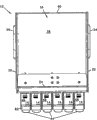
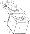
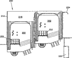
Fig. 1 is the front-side perspective view with communications component of a plurality of optic modules of installing through open front;
Fig. 2 is the front-side perspective view from the communications component as shown in fig. 1 of relative unilateral observation;
Fig. 3 is the front view of this communications component as shown in fig. 1;
Fig. 4 is the vertical view of this communications component as shown in fig. 1;
Fig. 5 is the rear view of this communications component as shown in fig. 1;
Fig. 6 is the side view of this communications component as shown in fig. 1;
Fig. 7 is the front-side perspective view of communications component as shown in fig. 1, and one of them module is separated from this assembly, and has removed mounting flange from the upper and lower surface of casing;
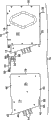
Fig. 8 is the backside perspective view of communications component as shown in Figure 7;
Fig. 9 is the side view of communications component as shown in Figure 7, and wherein the fiber adapter keeper is separated from this assembly;
Figure 10 is a communications component as shown in fig. 1 through the side cross-sectional view of the center institute intercepting that is installed in a module in this assembly;
Figure 11 is the front view of communications component as shown in fig. 1, wherein with a module removal so that the adapter keeper that is installed in this component internal to be shown;
Figure 12 is the front-side perspective view of the adapter keeper shown in the Figure 11 that from assembly, shifts out;
Figure 13 is the front view of the adapter keeper shown in Figure 12;
Figure 14 is the rear view of the adapter keeper shown in Figure 12;
Figure 15 is the side view of the adapter keeper shown in Figure 12;
Figure 16 is the vertical view of the adapter keeper shown in Figure 12;
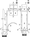
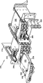
Figure 17 is the front-side perspective view according to selectable communications component of the present invention, wherein has a plurality of fiber optic splitter modules to be installed in the casing, and has two modules to separate from their installed position;
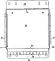
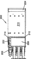
Figure 18 is the front view of this communications component as shown in Figure 17;
Figure 19 is the vertical view of this communications component as shown in Figure 17;
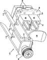
Figure 20 is the upward view of communications component as shown in Figure 17, and it has and is installed in the cable management structure of closing on this casing one side;
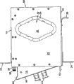
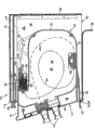
Figure 21 is the vertical view of communications component as shown in Figure 20, and wherein the top of casing is removed;
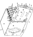
Figure 22 is the front-side perspective view of communications component as shown in Figure 21, and one of them module is separated from its installation site in casing;
Figure 23 is first side view of this communications component as shown in Figure 20;
Figure 24 is second side view of this communications component as shown in Figure 20;
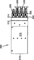
Figure 25 be with two module removals the front view of this communications component as shown in Figure 20;
Figure 26 is the rear view of this communications component as shown in Figure 25;
Figure 27 is the front view of the casing of communications component as shown in Figure 25 that module and adapter assembly are removed in the casing;
Figure 28 is the rear view of casing as shown in Figure 27;
Figure 29 is first side view of casing as shown in Figure 27;
Figure 30 is second side view of casing as shown in Figure 27;
Figure 31 is the vertical view of casing as shown in Figure 27;
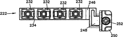
Figure 32 is the vertical view according to adapter assembly of the present invention, the standard pipe close that it has the dust plug (dust plug) of the extension of the front end that is inserted in each adapter and is inserted in each adapter rear end;
Figure 33 be as shown in Figure 32 adapter assembly look up partial, exploded perspective view;
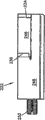
Figure 34 is the front view of adapter assembly as shown in Figure 32;
Figure 35 is first side view of adapter assembly as shown in Figure 32;
Figure 36 is the front-side perspective view of adapter assembly as shown in Figure 32, and wherein dust plug removes from adapter, and brake lining is partly separated from its installation site of closing on adapter;
Figure 37 is the front view of adapter assembly as shown in Figure 36;
Figure 38 is the rear view of adapter assembly as shown in Figure 36;
Figure 39 is first side view of adapter assembly as shown in Figure 36;
Figure 40 is second side view of adapter assembly as shown in Figure 36;
Figure 41 is the vertical view of adapter assembly as shown in Figure 36;
Figure 42 is the upward view of adapter assembly as shown in Figure 36, and wherein, the inlet panel that is used for each adapter of assembly is removed;
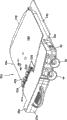
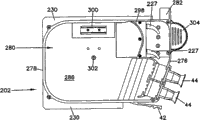
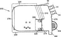
Figure 43 is the birds-eye perspective of the splitter module that uses with as shown in Figure 17 assembly according to the present invention;
Figure 44 be as shown in Figure 43 splitter module look up decomposition diagram;
Figure 45 is the upward view of splitter module as shown in Figure 44 that top cover is removed;
Figure 46 is the vertical view of this splitter module as shown in Figure 43;
Figure 47 is the upward view of this splitter module as shown in Figure 43;
Figure 48 is first side view of this splitter module as shown in Figure 43;
Figure 49 is second side view of this splitter module as shown in Figure 43;
Figure 50 is the rear view of this splitter module as shown in Figure 43;
Figure 51 is the front view of this splitter module as shown in Figure 43.
Embodiment
Reference numeral is used specifically in exemplary description of the present invention, and it is shown in the subsidiary accompanying drawing.Under possible situation, same Reference numeral is used for TYP or similar parts in all accompanying drawings.
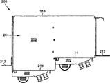
Accompanying drawing 1 shows communications component 10, and it has the installation site 12 that is used to install a plurality of modules 14.Assembly 10 comprises casing or housing 16, and casing or housing 16 comprise first major opposing side 18, second major opposing side 20 and a pair of relative transverse side 22 that between first and second major opposing sides, extends.Mounting flange 24 can be installed on each major opposing side and roughly reciprocally extend.Thereby second or selectable mounting flange 26 also can be installed in to provide on one of them major opposing side housing 16 is installed to the selection on the device of equipment frame, casing or other types of specific dimensions or shape.
Referring to accompanying drawing 2, each module 14 comprises the releasable locking bar 42 that closes on second major opposing side 20.Shown in Lower Half in the accompanying drawing 10, thereby the engagement of the part of locking bar 42 and housing 16 keeps module 14 in open front 28, and locking bar 42 can be deflected to allow module 14 to recall from housing 16.Each module 14 can comprise that also one or more is from front surface 46 extended cable outlets 44.Cable outlet 44 makes the module 14 interior communications cables be directed to the outside of module 14, as combining the description of Figure 10 below.Shown in accompanying drawing 2, the front surface of module 14 46 is angled with open front 28, the direction that its cable that can help to come out from module 14 is hoped towards the communicator.In scope disclosed by the invention, can predict, front surface 46 can be formed in the leading edge 38 that open front 28 places are basically parallel to transverse side 22.
Referring to accompanying drawing 3, module 14 comprises the flange 48 and 50 of different length, and they are received in respectively in the slit 52 and 54 of corresponding size.The size of flange 48 and slit 52 is littler than the size of flange 50 and slit 54.The size of slit 52 makes flange 48 can be received in the slit 52, and bigger flange 50 can not be mounted wherein.Guarantee that so module 14 is positioned on the open front 28 desirable directions.The similar United States Patent (USP) NO.5 that enjoys the public of flange describes in 363,465 to some extent, and its disclosed content is quoted at this as a reference.The adapter keeper 56 that remains on releasedly in the open front 28 through wing screw 58 is mounted to housing 16 at each 12 place, installation site on the contrary with locking bar 42.With reference to accompanying drawing 9 to 16, adapter keeper 56 will be specifically described below further.
Referring to attaching Figure 4 and 5, housing 16 comprises opposite with open front 28 back surperficial 60 further, its base closed the rear portion of housing 16.Can provide the opening that passes surface, back 60 with permission cable and air communication mistake, but desired operation person get into the inside 30 of housings 16 through open front 28.Shown in accompanying drawing 6, on an end of module 14, can comprise that edge or finger grip 62 are used for helping module 14 is shifted out from housing 16.Finger grip 62 preferably is positioned on the module 14 to be located with locking bar 42 on the contrary, makes the operator can use the relative strength of finger or hand to come to catch safely module and it is shifted out housing 16.
Referring to accompanying drawing 7, the locking bar 42 of module 14 can comprise recessed zone 66, its with edge 64 engagements of installation site 12 with maintenance module 14 in open front 28.Recessed zone 66 is formed on the end of closing on locking bar 42, and compliant member 68 extends to the position that is connected with first side 70 of module 14 from recessed zone 66.Compliant member 68 elastically deformables, and allow operator's deflection locking bar 42 to make recessed zone 66 and edge 64 remove engagement and from housing 16, remove module 14, perhaps, module 14 meshes when being inserted in the open front 28 with locking bar 42 deflections and with edge 64.Module 14 comprises second opposite flank 72 and rear portion 78.Middle back surperficial 76 are formed in second side 72 through inserting side face component 74.The a pair of joints of optical fibre 80 are positioned at back surface 76, and the fiber adapter that is used on the adapter keeper 56 interior with being installed to housing 16 inner 30 matches.
Figure 10 shows the cross-sectional view of assembly 10, and it has first cable, 94, the first cables 94 that extend to optics 98 from connector 80 and is installed in the inside 96 of module housing 40.Optics 98 can be the main optical element of beam splitter or fan-shaped bifurcated or other type.First cable 94 can be the multiple beams of optical fiber cable with a plurality of fibre bundles, and optics 98 can be fan-shaped bifurcated, is used for independent multi beam is separated into each in a plurality of second cables 100.Second cable 100 extends to cable outlet 44 from optics 98.Selectable, first cable 94 can be single optical fiber, and its signal is used as 98 separation of optics of beam splitter, and can extend to cable outlet 44 from a plurality of second cables 100 that carry from the part signal of first cable 94.The setting of optical fiber and cable export the U.S. Patent application NO.10/658 that the cover at 44 places is enjoyed the public, describe to some extent in 802, and its disclosed content is quoted at this as a reference.
Referring to accompanying drawing 11, a module of assembly 10 removes from an installation site 12, and comprises alternative adapter keeper 154 at these 12 places, installation site.Keeper 154 comprises protective cover 108, and it is positioned at the front of second end 92 of adapter 88.In some devices, before module 14 was placed in relevant installation site 12, housing 16 can be directed to and be connected to first end 90 of adapter 88 by installing and cable 102.If cable 102 is by light illumination and transmitting optical signal, protective cover 108 can be protected the accidental exposure of these signals, and this accidental exposure possibly damage eyes or near the perhaps communicator of other Sensitive Apparatus.
In accompanying drawing 12, keeper 154 comprises the opening 124 that passes extension 86, through said opening mounting adapter 88.Wing screw 56 extends through forward flange 114, and a pair of wall cooperates flange 116 to extend back from adjacent forward flange 114.Selectively, other releasable part, the wing screw 56 that can substitute on keeper 54 or 154 like clamping close device, right-angled bend securing member, expansion locking bar or similar part uses.Between the front end of each flange 116 and forward flange 114, has slit 118.Has a pair of wall slit 120 towards the rear end of flange 116.Shown in accompanying drawing 10, inwall 110 be arranged in inner 30 from first first type surface 18 to bias internal.Wall slit 120 extends along the both sides of inwall 110.The leading edge 112 of the interior folding of first first type surface 18 matches with slit 118.The inwall 110 that cooperation between housing 16 and the keeper 154 departs from inner 30 adapter is correctly located, thus make its with module 14 back surperficial 76 on connector 80 match.Central module 122 extends to extension 86 from the forward flange between wall flange 116 114, thereby correctly adapter 88 is installed in the inside 30 between open front 28 and the rear portion 60.
Referring to accompanying drawing 13 to 16, the extension 86 of keeper 154 comprises a plurality of fastener holes 124 of mounting adapter 88 to the extension 86 that are used for.Securing member 126 can be extended side flange 128 through adapter 88 to realize mounting adapter 88 firmly.Adapter 88 is illustrated as SC connector, though the adapter of other type and form also can use in scope disclosed by the invention, connector 80 and 104 is changed to cooperate these selectable adapters.In each adapter 88 that illustrates an alignment device (for example the crack sleeve 130) can be arranged, be used for the optical fiber that positioning end correctly is connected to lasso and is supported by connector 80 and 104.Aforesaid alignment device and termination lasso belong to prior art.
See that from the side protective cover 108 is crooked, shown in accompanying drawing 15, like this when module 14 is inserted in inner 30 through open front 28, thereby protective cover 108 can be closely cooperated with adapter 88 by module 14 deflection connectors 80.Protective cover 108 is preferably processed by resilient material, when module 14 from the installation site 12 when recalling, it can return to the position shown in accompanying drawing 15.Protective cover 108 can be connected on the central module 122 through the securing member of a pair of for example screw 132.Selectable, protective cover 108 can be through being formed by keeper 154 or being connected on the keeper 154 through spot welding or other tightening technology.Because the rear portion of housing 16 has been sealed at rear portion 60; So do not lead to the path at the rear portion of any module 14 that is installed in 12 places, installation site, as shown in the figurely there is no need to be provided with again second protective cover 108 and be used to stop light from first end 90 of each adapter 88.But,, first side 90 that second protective cover 108 is used to stop adapter 88 is installed preferably if any Sensitive Apparatus is installed in module 14 or the housing 16.
12 places, an installation site that module 14 is inserted into housing 16 can comprise at first unclamps wing screw 56 and shifts out keeper 54 or 154 in 30 internally through open front 28.Thereby cable 102 preferably includes enough extra lengths or slackness in inner 30 allows adapter 88 to be drawn out from opening 28.In case be positioned at beyond inner 30, thereby the connector 104 of cable 102 can shift out the polished end faces that can clean optical fiber the cable 102 from first end 90 of adapter 88.Connector 104 can be inserted in first end 90 again then.Keeper 54 or 154 can be inserted in inner 30 again, so that this keeper and inwall 110 and interior folding extension 112 matches and fixed-wing shape screw 56 again.Module 14 is inserted into open front 28 makes module 14 be coupled to housing 16 and adapter 88.When module 14 was inserted, flange 48 and 50 cooperated respectively with slit 52 and 54.When connector 80 during near second end 92 of adapter 88, connector 80 cooperates and deflection protective covers 108 (if any) with part second side 72.Further insert module 14 is introduced connector 80 and it is contacted with adapter 88, and said connector is received in second end 92.When module 14 was inserted into, locking bar 42 was rebounded to intrinsic deflection then, made recessed zone 66 cooperate with edge 64.Module 14 12 places, installation site be installed in open front 28 with inner 30 in, and be positioned at suitable position, with first cable 94, optics 98 and 100 processing of second cable through inside modules 96 and transmission signal from cable 102.
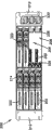
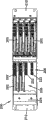
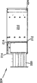
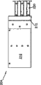
Referring to accompanying drawing 17 to 19, the embodiment 200 of selectable communications component comprises a plurality of fiber optic splitter modules 202 that are installed in 206 places, installation site in the casing 204 anterior 214.Casing 204 comprises top 208, a pair of relative side 210 and a pair of from the side 210 outward extending mounting flanges near front portion 214.Casing 204 also comprises rear portion 216.Anterior 214 define the installation site 206 of a pair of vertical stacking structure, thus its each other in the past backward skew improved the cable path of the optical fiber cable of stretching from module 202.
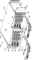
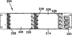
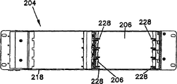
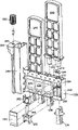
Accompanying drawing 20 to 26 shows assembly 200, and it has the cable management structure 220 and bottom 218 that is installed on one of mounting flange 212.Two modules 202 206 are moved out of from the installation site.Specifically referring to accompanying drawing 21 and 22, to connector 226, they were received in the adapter assembly 222 that is positioned each 206 place, installation site after each module 202 comprised nearly four.As shown in the figure, the rear portion 218 of casing 204 is open for the optical fiber cable that extends to adapter assembly 222 rear sides, and close on 218 places, rear portion install the rear cables protector with the cable guide that helps these rear portions and get into to adapter assembly 222.Each adapter assembly 222 comprises nearly four fiber adapter 232, and it has the structure that receives the connector of the optical fiber cable that gets into from behind in front end reception back to one of connector 226 with in end opposite.
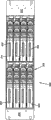
Referring to accompanying drawing 27 to 31, each installation site 206 comprises a pair of relative slit 228, and the connector 226 of locating module 202 makes it cooperate with adapter assembly 222 when slit 228 cooperates with the flange 230 that extends from the side of module 202.
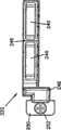
Accompanying drawing 32 to 35 shows the adapter assembly of removing from casing 204 222.Adapter assembly 222 comprises the adapter 232 of four one, and each adapter has rear end 234 and front end 236.Shown in Figure 32 and 33, dust plug 238 is arranged in each rear end 234 and two dust plugs 240 of prolonging are inserted into the front end of every pair of adapter 232, is used for the inside and the pollutant of adapter 232 are kept apart.Adapter assembly 222 comprises that adapter housing section 246 and casing install slideway 248, and housing section 246 inside are installed on adapter 232, and this casing is installed slideway and is received in the casing 204 through front end 214 and matches with casing 204 and be used for confirming installation site 206.Flange 250 extends from slideway 248 is installed, and, be used for the wing screw 252 that adapter assembly 222 is fixed in the casing 204 is extended through flange 250.Screw 252 is positioned at hole 254, and captive fastener preferably, though other securing member also is operable.
Shown in figure 33, each adapter 232 is positioned at housing section 246.The element of adapter 232 is orientated as through opening 256 and is got into adapter recess 258.The element of each adapter 232 comprises ferrule alignment sleeve (ferrule alignment sleeve) 260 and a pair of inner housing half one 262.These elements are positioned at the mode of recess 258 and announce in the United States Patent (USP) NO.5 on May 20th, 1993, and 317,663 is similar, and wherein disclosed content is quoted at this as a reference.Panel 264 has sealed opening 256 and has protected the element in each adapter 232.
Referring to accompanying drawing 36 to 41, brake lining 244 is arranged in the open front 266 of front end 236 of each adapter 232 so that lightstruck protection to be provided.Describe to some extent in being disclosed in the PCT publication number WO 03/093889A 1 on November 12nd, 2003 with brake lining 244 similar brake linings, its disclosed content is quoted at this as a reference.Brake lining 244 slips in the slit 268 in the housing section 246.Teat 270 extends and matches so that brake lining 244 is held in place each adapter 232 with teat recess 272 from brake lining 244.When brake lining 244 connects the function of optical fiber cables when unnecessary for adapter 232, it also can provide the protection of the accidental optical signal exposure that prevents operator or Other Instruments are damaged.Preferably, brake lining 244 not be inserted into each adapter 232 in connector ring cooperate.But connector shell is released brake lining 244.
Accompanying drawing 42 shows inlet panel 264 is removed so that the adapter assembly 222 of the element of each adapter 232 in the recess 258 to be shown.
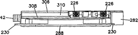
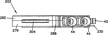
Accompanying drawing 43 shows splitter module 202, its have be used for casing 204 in the side flange 230 that matches of the slit 228 of installation site 206.Connector 226 is seated on the front portion 276 and the insertion wallboard 274 between the rear portion 278 of module bodies 280.Threaded cap (screw cover) flange 282 extends one of from a pair of side 284 of main body 280, and locking bar 42 284 extends from the another side.When module 202 is installed in the casing 204, the screw 252 of flange 282 extend through adapter assemblies 222.So just prevented that when module 202 is installed in 206 places, installation site adapter assembly 222 is moved or screw 252 unclamps.Cable outlet 44 provides in main body 280 passes through anterior 276 optical fibre channel, so optical fiber can extend through cable management structure 220 and extend to other communication device.
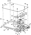
Referring to accompanying drawing 44, module 202 comprises the inside of being confirmed by main body 280 and the base plate that can remove 288 286, and base plate 288 is remained on the main body 280 by a plurality of removable securing members (for example screw 290).A pair of fibre-optical fixator 292 is installed in the back of closing on each cable outlet 44 in inner 286.As before described module 14, module 202 is preferably held beam splitter, it at one end receives single fibre bundle and receives a plurality of fibre bundles at the other end.After comprising nearly four, module 202, and therefore can comprise nearly four beam splitters (not shown in the accompanying drawing 44) to connector 226.In inner 286, each connector 226 can comprise that the strain relief boot 227 of be with angle is used for realizing being terminated at the direction change of the optical fiber of connector 226.
286 outside can be near connector 226 internally through the opening on the main body 280 292.Connector mounting blocks 296 and connector 226 are spaced apart and guarantee that connector 226 contacts with the adapter 232 of adapter assembly 222 and cooperates.Mounting blocks 296 also comprises top cable guide piece 298, and this device is used for arranging cable at inner 286 connectors 226 with between exporting 44.In inner 286, beam splitter assembly parts 300 be can also comprise, one or more optical beam-splitters or other optics interior are used to locate with stuck-module 202.Thereby centre post and threaded block 302 also can be placed the extra support that wherein provides base plate 288.The grasping that finger grip or handle 304 extend to provide convenience from front portion 276 is used for module 202 is removed from casing 204, perhaps helps operation.
Referring to accompanying drawing 45 to 51; Module 202 comprises big degree of depth part 306 and shallow degree of depth part 308; Big degree of depth part 306 is closed on front portion 276, and connector 226 with the optical fiber guiding that gets into wherein, and shallow degree of depth part 308 begins to extend to rear portion 278 from closing on connector 226 always.The quantity that can be installed in the connector 226 on the module 202 does not allow side 284 to move towards each other, and has reduced by inner 286 width, can not occupy too many cable wiring space in inner 286.Partial depth part 308 278 extends to connector 226 and makes that adapter can be overlapping with main body 280 from the rear portion, and this is impossible for aforesaid module 14.But the degree of depth that reduces has reduced the volume of inside 286 really can not require to have adverse effect to the bending radius in inner 286.Transition member 310 is provided at seamlessly transitting between the part 306 and 308 degree of depth.Seamlessly transit can reduce the sharp angles that optical fiber possibly run into well in inner 286, and make form or manufacturing main body 280 easier.
In module 202, the top that connector 226 is positioned at main body 280 is scope to the bottom, that is, between side 284, and insert from the back extension that leans on most of module 202, for example, rear portion 278.
Above-mentioned specific descriptions, example and data have provided the detailed description that the present invention uses and makes.Because a lot of embodiment of the present invention can make not departing from scope of the present invention and spirit, so the present invention forgives in the scope of invention that claim limited of attaching.
Claims (9)
1. fiber optic adapter module comprises:
Main body with one of housing section and installation portion, housing section and installation portion form integral unit, the main part limitation of said one the longitudinal axis;
Housing section defines at least one fiber adapter that forms integral unit with housing section; First and second transverse sides that housing section defines top, bottom and between top and bottom, extends; Each fiber adapter of housing section comprises the open front that is used to receive first joints of optical fibre, be used to receive second joints of optical fibre that are suitable for cooperating with first joints of optical fibre after-opening, be used to receive the side opening of ferrule alignment sleeve and a pair of inner housing half one; Housing section comprises panel, and panel has sealed the side opening of said at least one fiber adapter so that ferrule alignment sleeve and a pair of inner housing half one are remained in the fiber adapter;
Said installation portion is designed to the main body of said one is mounted to a communication device; Said installation portion comprises the installation slideway; Be used for slidably fiber optic adapter module being inducted into this part communication device; The top that slideway and housing section be installed forms integral unit and extends along the longitudinal axis of the main body of said one, and installation portion defines on the direction opposite with housing section from the flange that the slideway extension is left is installed, and said flange is used for fiber optic adapter module is mounted to this part communication device.
2. fiber optic adapter module as claimed in claim 1, wherein flange defines the face that extends perpendicular to the said longitudinal axis.
3. fiber optic adapter module as claimed in claim 1; Wherein this part communication device comprises the communication casing; The communication casing defines open front and after-opening, and installation structure is for to be positioned at housing section in the casing, and said at least one fiber adapter can be approaching through the open front and the after-opening of casing.
4. fiber optic adapter module as claimed in claim 1, wherein each fiber adapter comprises the removable brake lining that is installed in the open front, it is used to stop that the light of launching from after-opening is through open front.
5. fiber optic adapter module as claimed in claim 4, wherein each removable brake lining is installed in the slit of the open front that closes on fiber adapter.
6. fiber optic adapter module as claimed in claim 5, the teat opening that wherein closes on said slit in the teat through making brake lining and the housing section is meshed, and said removable brake lining is maintained in the slit.
7. fiber optic adapter module as claimed in claim 1 comprises four fiber adapter in the wherein said housing section.
8. fiber optic adapter module as claimed in claim 1, but wherein said flange comprises and is used for fiber optic adapter module is installed in the release fasteners in this part communication device.
9. fiber optic adapter module as claimed in claim 8, but the wing screw that wherein said release fasteners is kept by said flange mooring.
Applications Claiming Priority (2)
| Application Number | Priority Date | Filing Date | Title |
|---|---|---|---|
| US11/138,889 | 2005-05-25 | ||
| US11/138,889 US7376323B2 (en) | 2005-05-25 | 2005-05-25 | Fiber optic adapter module |
Related Parent Applications (1)
| Application Number | Title | Priority Date | Filing Date |
|---|---|---|---|
| CN2006800178652A Division CN101180561B (en) | 2005-05-25 | 2006-05-18 | Fiber optic adapter module consisting of plurality of integrally formed adapters |
Publications (2)
| Publication Number | Publication Date |
|---|---|
| CN101846774A CN101846774A (en) | 2010-09-29 |
| CN101846774B true CN101846774B (en) | 2012-06-20 |
Family
ID=37011924
Family Applications (2)
| Application Number | Title | Priority Date | Filing Date |
|---|---|---|---|
| CN2006800178652A Expired - Fee Related CN101180561B (en) | 2005-05-25 | 2006-05-18 | Fiber optic adapter module consisting of plurality of integrally formed adapters |
| CN2010101244626A Expired - Fee Related CN101846774B (en) | 2005-05-25 | 2006-05-18 | Fiber optic adapter module |
Family Applications Before (1)
| Application Number | Title | Priority Date | Filing Date |
|---|---|---|---|
| CN2006800178652A Expired - Fee Related CN101180561B (en) | 2005-05-25 | 2006-05-18 | Fiber optic adapter module consisting of plurality of integrally formed adapters |
Country Status (10)
| Country | Link |
|---|---|
| US (3) | US7376323B2 (en) |
| EP (1) | EP1883844B1 (en) |
| JP (1) | JP2008542822A (en) |
| KR (1) | KR101234430B1 (en) |
| CN (2) | CN101180561B (en) |
| AU (1) | AU2006249421B2 (en) |
| BR (1) | BRPI0611416B1 (en) |
| MX (1) | MX2007014686A (en) |
| TW (1) | TWI460483B (en) |
| WO (1) | WO2006127397A1 (en) |
Families Citing this family (169)
| Publication number | Priority date | Publication date | Assignee | Title |
|---|---|---|---|---|
| US5883995A (en) | 1997-05-20 | 1999-03-16 | Adc Telecommunications, Inc. | Fiber connector and adapter |
| US6885798B2 (en) | 2003-09-08 | 2005-04-26 | Adc Telecommunications, Inc. | Fiber optic cable and furcation module |
| US6920274B2 (en) * | 2003-12-23 | 2005-07-19 | Adc Telecommunications, Inc. | High density optical fiber distribution frame with modules |
| US20060059664A1 (en) * | 2004-09-20 | 2006-03-23 | Sheng Yang S | Button structure |
| US7576997B2 (en) * | 2004-09-20 | 2009-08-18 | Fujitsu Limited | Backplane extension apparatus and method |
| US7376322B2 (en) * | 2004-11-03 | 2008-05-20 | Adc Telecommunications, Inc. | Fiber optic module and system including rear connectors |
| US7376323B2 (en) * | 2005-05-25 | 2008-05-20 | Adc Telecommunications, Inc. | Fiber optic adapter module |
| US7400813B2 (en) * | 2005-05-25 | 2008-07-15 | Adc Telecommunications, Inc. | Fiber optic splitter module |
| US7636507B2 (en) * | 2005-06-17 | 2009-12-22 | Adc Telecommunications, Inc. | Compact blind mateable optical splitter |
| US7346254B2 (en) * | 2005-08-29 | 2008-03-18 | Adc Telecommunications, Inc. | Fiber optic splitter module with connector access |
| US7623749B2 (en) * | 2005-08-30 | 2009-11-24 | Adc Telecommunications, Inc. | Fiber distribution hub with modular termination blocks |
| US7330626B2 (en) * | 2005-08-31 | 2008-02-12 | Adc Telecommunications, Inc. | Cabinet including optical bulkhead plate for blown fiber system |
| JP3987078B2 (en) * | 2005-08-31 | 2007-10-03 | 日本電信電話株式会社 | Optical connector |
| US7245809B1 (en) * | 2005-12-28 | 2007-07-17 | Adc Telecommunications, Inc. | Splitter modules for fiber distribution hubs |
| US7816602B2 (en) | 2006-02-13 | 2010-10-19 | Adc Telecommunications, Inc. | Fiber distribution hub with outside accessible grounding terminals |
| US7418181B2 (en) * | 2006-02-13 | 2008-08-26 | Adc Telecommunications, Inc. | Fiber optic splitter module |
| US7720343B2 (en) | 2006-02-13 | 2010-05-18 | Adc Telecommunications, Inc. | Fiber distribution hub with swing frame and modular termination panels |
| US7689089B2 (en) * | 2006-10-11 | 2010-03-30 | Panduit Corp. | Release latch for pre-terminated cassette |
| US7583885B2 (en) * | 2006-11-28 | 2009-09-01 | Adc Telecommunications, Inc. | Fiber distribution enclosure |
| US7522805B2 (en) * | 2007-03-09 | 2009-04-21 | Adc Telecommunications, Inc. | Wall mount distribution arrangement |
| JP4343238B2 (en) * | 2007-05-29 | 2009-10-14 | 日本航空電子工業株式会社 | Assembly |
| US7391954B1 (en) | 2007-05-30 | 2008-06-24 | Corning Cable Systems Llc | Attenuated optical splitter module |
| US20080298748A1 (en) * | 2007-05-31 | 2008-12-04 | Terry Dean Cox | Direct-connect optical splitter module |
| US20080298743A1 (en) * | 2007-05-31 | 2008-12-04 | Konstantinos Saravanos | Microsplitter module for optical connectivity |
| US7590328B2 (en) * | 2007-08-02 | 2009-09-15 | Adc Telecommunications, Inc. | Fiber termination block with splitters |
| US8798427B2 (en) | 2007-09-05 | 2014-08-05 | Corning Cable Systems Llc | Fiber optic terminal assembly |
| EP2203769A1 (en) * | 2007-10-22 | 2010-07-07 | ADC Telecommunications, Inc. | Fiber distribution hub |
| US7536075B2 (en) | 2007-10-22 | 2009-05-19 | Adc Telecommunications, Inc. | Wavelength division multiplexing module |
| US7885505B2 (en) | 2007-10-22 | 2011-02-08 | Adc Telecommunications, Inc. | Wavelength division multiplexing module |
| US7751672B2 (en) | 2007-10-31 | 2010-07-06 | Adc Telecommunications, Inc. | Low profile fiber distribution hub |
| US8229265B2 (en) | 2007-11-21 | 2012-07-24 | Adc Telecommunications, Inc. | Fiber distribution hub with multiple configurations |
| US8238709B2 (en) | 2007-12-18 | 2012-08-07 | Adc Telecommunications, Inc. | Multi-configuration mounting system for fiber distribution hub |
| US8107816B2 (en) | 2008-01-29 | 2012-01-31 | Adc Telecommunications, Inc. | Wavelength division multiplexing module |
| US8249410B2 (en) * | 2008-04-25 | 2012-08-21 | Corning Cable Systems Llc | Connector housing for a communication network |
| US8382382B2 (en) | 2008-08-27 | 2013-02-26 | Adc Telecommunications, Inc. | Fiber optic adapter with integrally molded ferrule alignment structure |
| US8184938B2 (en) | 2008-08-29 | 2012-05-22 | Corning Cable Systems Llc | Rear-installable fiber optic modules and equipment |
| US8452148B2 (en) | 2008-08-29 | 2013-05-28 | Corning Cable Systems Llc | Independently translatable modules and fiber optic equipment trays in fiber optic equipment |
| US11294135B2 (en) | 2008-08-29 | 2022-04-05 | Corning Optical Communications LLC | High density and bandwidth fiber optic apparatuses and related equipment and methods |
| US20100322583A1 (en) | 2009-06-19 | 2010-12-23 | Cooke Terry L | High Density and Bandwidth Fiber Optic Apparatuses and Related Equipment and Methods |
| US7856166B2 (en) | 2008-09-02 | 2010-12-21 | Corning Cable Systems Llc | High-density patch-panel assemblies for optical fiber telecommunications |
| CN102209921B (en) | 2008-10-09 | 2015-11-25 | 康宁光缆系统有限公司 | There is the fibre-optic terminus supported from the adapter panel of the input and output optical fiber of optical splitters |
| US8879882B2 (en) | 2008-10-27 | 2014-11-04 | Corning Cable Systems Llc | Variably configurable and modular local convergence point |
| MX2011005380A (en) | 2008-11-21 | 2011-06-06 | Adc Telecommunications Inc | Fiber optic telecommunications module. |
| WO2010083369A1 (en) | 2009-01-15 | 2010-07-22 | Adc Telecommunications, Inc. | Fiber optic module, chassis and adapter |
| EP2221932B1 (en) | 2009-02-24 | 2011-11-16 | CCS Technology Inc. | Holding device for a cable or an assembly for use with a cable |
| EP2237091A1 (en) | 2009-03-31 | 2010-10-06 | Corning Cable Systems LLC | Removably mountable fiber optic terminal |
| US8699838B2 (en) | 2009-05-14 | 2014-04-15 | Ccs Technology, Inc. | Fiber optic furcation module |
| US9075216B2 (en) | 2009-05-21 | 2015-07-07 | Corning Cable Systems Llc | Fiber optic housings configured to accommodate fiber optic modules/cassettes and fiber optic panels, and related components and methods |
| US8280216B2 (en) | 2009-05-21 | 2012-10-02 | Corning Cable Systems Llc | Fiber optic equipment supporting moveable fiber optic equipment tray(s) and module(s), and related equipment and methods |
| JP2012530943A (en) | 2009-06-19 | 2012-12-06 | コーニング ケーブル システムズ リミテッド ライアビリティ カンパニー | High fiber optic cable packaging density equipment |
| US8712206B2 (en) | 2009-06-19 | 2014-04-29 | Corning Cable Systems Llc | High-density fiber optic modules and module housings and related equipment |
| AU2010202453A1 (en) * | 2009-06-19 | 2011-01-13 | Corning Cable Systems Llc | Fiber optic module assembly having improved finger access and labeling indicia |
| ES2403007A1 (en) * | 2009-07-01 | 2013-05-13 | Adc Telecommunications, Inc | Wall-mounted fiber distribution hub |
| US8606067B2 (en) * | 2009-09-04 | 2013-12-10 | Adc Telecommunications, Inc. | Pedestal terminal with swing frame |
| US8467651B2 (en) | 2009-09-30 | 2013-06-18 | Ccs Technology Inc. | Fiber optic terminals configured to dispose a fiber optic connection panel(s) within an optical fiber perimeter and related methods |
| US9261654B2 (en) | 2009-10-13 | 2016-02-16 | Leviton Manufacturing Co., Inc. | Fiber optic adapter plates with integrated fiber optic adapters |
| US20110129185A1 (en) * | 2009-11-30 | 2011-06-02 | Lewallen C Paul | Articulated Strain Relief Boot on a Fiber Optic Module and Associated Methods |
| US8625950B2 (en) | 2009-12-18 | 2014-01-07 | Corning Cable Systems Llc | Rotary locking apparatus for fiber optic equipment trays and related methods |
| US8824850B2 (en) * | 2010-01-26 | 2014-09-02 | Adc Telecommunications, Inc. | Insect-infestation prevention device for a telecommunications equipment housing |
| US8593828B2 (en) | 2010-02-04 | 2013-11-26 | Corning Cable Systems Llc | Communications equipment housings, assemblies, and related alignment features and methods |
| CN102870021B (en) | 2010-03-02 | 2015-03-11 | 蒂安电子服务有限责任公司 | Fibre-optic telecommunication module |
| US9547144B2 (en) | 2010-03-16 | 2017-01-17 | Corning Optical Communications LLC | Fiber optic distribution network for multiple dwelling units |
| US8913866B2 (en) | 2010-03-26 | 2014-12-16 | Corning Cable Systems Llc | Movable adapter panel |
| CN102884469B (en) | 2010-04-16 | 2016-09-28 | Ccs技术股份有限公司 | Sealing and strain relief means for data cable |
| US8792767B2 (en) | 2010-04-16 | 2014-07-29 | Ccs Technology, Inc. | Distribution device |
| EP2381284B1 (en) | 2010-04-23 | 2014-12-31 | CCS Technology Inc. | Under floor fiber optic distribution device |
| EP2564250A4 (en) | 2010-04-27 | 2013-11-13 | Adc Comm Shanghai Co Ltd | Fiber optic module and chassis |
| US9720195B2 (en) | 2010-04-30 | 2017-08-01 | Corning Optical Communications LLC | Apparatuses and related components and methods for attachment and release of fiber optic housings to and from an equipment rack |
| US9075217B2 (en) | 2010-04-30 | 2015-07-07 | Corning Cable Systems Llc | Apparatuses and related components and methods for expanding capacity of fiber optic housings |
| US9632270B2 (en) | 2010-04-30 | 2017-04-25 | Corning Optical Communications LLC | Fiber optic housings configured for tool-less assembly, and related components and methods |
| US8705926B2 (en) | 2010-04-30 | 2014-04-22 | Corning Optical Communications LLC | Fiber optic housings having a removable top, and related components and methods |
| US8660397B2 (en) | 2010-04-30 | 2014-02-25 | Corning Cable Systems Llc | Multi-layer module |
| US9519118B2 (en) | 2010-04-30 | 2016-12-13 | Corning Optical Communications LLC | Removable fiber management sections for fiber optic housings, and related components and methods |
| US8879881B2 (en) | 2010-04-30 | 2014-11-04 | Corning Cable Systems Llc | Rotatable routing guide and assembly |
| US11251608B2 (en) | 2010-07-13 | 2022-02-15 | Raycap S.A. | Overvoltage protection system for wireless communication systems |
| US8718436B2 (en) | 2010-08-30 | 2014-05-06 | Corning Cable Systems Llc | Methods, apparatuses for providing secure fiber optic connections |
| WO2012054454A2 (en) | 2010-10-19 | 2012-04-26 | Corning Cable Systems Llc | Transition box for multiple dwelling unit fiber optic distribution network |
| US9279951B2 (en) | 2010-10-27 | 2016-03-08 | Corning Cable Systems Llc | Fiber optic module for limited space applications having a partially sealed module sub-assembly |
| US8662760B2 (en) | 2010-10-29 | 2014-03-04 | Corning Cable Systems Llc | Fiber optic connector employing optical fiber guide member |
| US9116324B2 (en) | 2010-10-29 | 2015-08-25 | Corning Cable Systems Llc | Stacked fiber optic modules and fiber optic equipment configured to support stacked fiber optic modules |
| CA2819235C (en) | 2010-11-30 | 2018-01-16 | Corning Cable Systems Llc | Fiber device holder and strain relief device |
| CN103380391B (en) | 2011-02-02 | 2016-04-13 | 康宁光缆系统有限责任公司 | Be applicable to set up optics and be connected to the optical backplane extension module of the information processing module be arranged in equipment rack and relevant assembly |
| WO2013105998A2 (en) | 2011-02-16 | 2013-07-18 | Tyco Electronics Corporation | Fiber optic closure |
| US9182563B2 (en) | 2011-03-31 | 2015-11-10 | Adc Telecommunications, Inc. | Adapter plate for fiber optic module |
| US9008485B2 (en) | 2011-05-09 | 2015-04-14 | Corning Cable Systems Llc | Attachment mechanisms employed to attach a rear housing section to a fiber optic housing, and related assemblies and methods |
| CN103649805B (en) | 2011-06-30 | 2017-03-15 | 康宁光电通信有限责任公司 | Fiber plant assembly of shell using non-U-width size and associated method |
| US8953924B2 (en) | 2011-09-02 | 2015-02-10 | Corning Cable Systems Llc | Removable strain relief brackets for securing fiber optic cables and/or optical fibers to fiber optic equipment, and related assemblies and methods |
| US9417401B2 (en) | 2011-09-06 | 2016-08-16 | Commscope Technologies Llc | Adapter for fiber optic module |
| US9229172B2 (en) | 2011-09-12 | 2016-01-05 | Commscope Technologies Llc | Bend-limited flexible optical interconnect device for signal distribution |
| US9417418B2 (en) | 2011-09-12 | 2016-08-16 | Commscope Technologies Llc | Flexible lensed optical interconnect device for signal distribution |
| US8770861B2 (en) | 2011-09-27 | 2014-07-08 | Tyco Electronics Corporation | Outside plant termination enclosure |
| US9057859B2 (en) | 2011-10-07 | 2015-06-16 | Adc Telecommunications, Inc. | Slidable fiber optic connection module with cable slack management |
| US9170391B2 (en) | 2011-10-07 | 2015-10-27 | Adc Telecommunications, Inc. | Slidable fiber optic connection module with cable slack management |
| US9002166B2 (en) | 2011-10-07 | 2015-04-07 | Adc Telecommunications, Inc. | Slidable fiber optic connection module with cable slack management |
| ES2855523T3 (en) | 2011-10-07 | 2021-09-23 | Commscope Technologies Llc | Fiber optic cassette, system and method |
| US8731364B2 (en) * | 2011-11-21 | 2014-05-20 | Ortronics, Inc. | Breakout assemblies and associated mounting members for fiber optic applications |
| US9038832B2 (en) | 2011-11-30 | 2015-05-26 | Corning Cable Systems Llc | Adapter panel support assembly |
| US9219546B2 (en) | 2011-12-12 | 2015-12-22 | Corning Optical Communications LLC | Extremely high frequency (EHF) distributed antenna systems, and related components and methods |
| US9075203B2 (en) | 2012-01-17 | 2015-07-07 | Adc Telecommunications, Inc. | Fiber optic adapter block |
| US10110307B2 (en) | 2012-03-02 | 2018-10-23 | Corning Optical Communications LLC | Optical network units (ONUs) for high bandwidth connectivity, and related components and methods |
| US20130308915A1 (en) * | 2012-05-16 | 2013-11-21 | Scott Eaker Buff | Port tap fiber optic modules, and related systems and methods for monitoring optical networks |
| US9004778B2 (en) | 2012-06-29 | 2015-04-14 | Corning Cable Systems Llc | Indexable optical fiber connectors and optical fiber connector arrays |
| US9250409B2 (en) | 2012-07-02 | 2016-02-02 | Corning Cable Systems Llc | Fiber-optic-module trays and drawers for fiber-optic equipment |
| US9049500B2 (en) | 2012-08-31 | 2015-06-02 | Corning Cable Systems Llc | Fiber optic terminals, systems, and methods for network service management |
| US9042702B2 (en) | 2012-09-18 | 2015-05-26 | Corning Cable Systems Llc | Platforms and systems for fiber optic cable attachment |
| US9195021B2 (en) * | 2012-09-21 | 2015-11-24 | Adc Telecommunications, Inc. | Slidable fiber optic connection module with cable slack management |
| US10082636B2 (en) | 2012-09-21 | 2018-09-25 | Commscope Technologies Llc | Slidable fiber optic connection module with cable slack management |
| US9146362B2 (en) | 2012-09-21 | 2015-09-29 | Adc Telecommunications, Inc. | Insertion and removal tool for a fiber optic ferrule alignment sleeve |
| US9146374B2 (en) | 2012-09-28 | 2015-09-29 | Adc Telecommunications, Inc. | Rapid deployment packaging for optical fiber |
| EP2901192B1 (en) | 2012-09-28 | 2020-04-01 | CommScope Connectivity UK Limited | Fiber optic cassette |
| EP2901191A4 (en) | 2012-09-28 | 2016-10-26 | Tyco Electronics Ltd Uk | Manufacture and testing of fiber optic cassette |
| US9223094B2 (en) | 2012-10-05 | 2015-12-29 | Tyco Electronics Nederland Bv | Flexible optical circuit, cassettes, and methods |
| US8909019B2 (en) | 2012-10-11 | 2014-12-09 | Ccs Technology, Inc. | System comprising a plurality of distribution devices and distribution device |
| ES2551077T3 (en) | 2012-10-26 | 2015-11-16 | Ccs Technology, Inc. | Fiber optic management unit and fiber optic distribution device |
| US10031305B2 (en) | 2012-12-19 | 2018-07-24 | CommScope Connectivity Belgium BVBA | Distribution device with incrementally added splitters |
| NZ708968A (en) | 2013-01-29 | 2018-03-23 | CommScope Connectivity Belgium BVBA | Optical fiber distribution system |
| US9128262B2 (en) | 2013-02-05 | 2015-09-08 | Adc Telecommunications, Inc. | Slidable telecommunications tray with cable slack management |
| WO2014133943A1 (en) | 2013-02-27 | 2014-09-04 | Adc Telecommunications, Inc. | Slidable fiber optic connection module with cable slack management |
| US8985862B2 (en) | 2013-02-28 | 2015-03-24 | Corning Cable Systems Llc | High-density multi-fiber adapter housings |
| CN105164560B (en) * | 2013-03-05 | 2017-03-22 | 菲尼萨公司 | Latch mechanism for communication module |
| US9435975B2 (en) | 2013-03-15 | 2016-09-06 | Commscope Technologies Llc | Modular high density telecommunications frame and chassis system |
| US9535226B2 (en) * | 2013-03-29 | 2017-01-03 | 3M Innovative Properties Company | Modular breakout device for optical and electrical connections |
| AP2015008820A0 (en) | 2013-04-24 | 2015-10-31 | Adc Czech Republic Sro | Optical fiber distribution system |
| NZ713590A (en) | 2013-04-24 | 2018-09-28 | CommScope Connectivity Belgium BVBA | Universal mounting mechanism for mounting a telecommunications chassis to a telecommunications fixture |
| US9301030B2 (en) | 2013-11-11 | 2016-03-29 | Commscope Technologies Llc | Telecommunications module |
| CN106133572B (en) | 2014-01-28 | 2018-11-09 | Adc电信公司 | Slidably optical link module with cable slack management |
| US9494758B2 (en) | 2014-04-03 | 2016-11-15 | Commscope Technologies Llc | Fiber optic distribution system |
| US10732370B2 (en) | 2014-06-17 | 2020-08-04 | CommScope Connectivity Belgium BVBA | Cable distribution system |
| US9395509B2 (en) | 2014-06-23 | 2016-07-19 | Commscope Technologies Llc | Fiber cable fan-out assembly and method |
| US10054753B2 (en) | 2014-10-27 | 2018-08-21 | Commscope Technologies Llc | Fiber optic cable with flexible conduit |
| EP3230780B1 (en) | 2014-12-10 | 2023-10-25 | CommScope Technologies LLC | Fiber optic cable slack management module |
| AU2016239875C1 (en) | 2015-04-03 | 2021-06-24 | CommScope Connectivity Belgium BVBA | Telecommunications distribution elements |
| US10302874B2 (en) | 2015-05-15 | 2019-05-28 | Commscope Telecommunications (Shanghai) Co., Ltd. | Alignment sleeve assembly and fiber optic adapter |
| AU2015207954C1 (en) | 2015-07-31 | 2022-05-05 | Adc Communications (Australia) Pty Limited | Cable breakout assembly |
| WO2017034931A1 (en) | 2015-08-21 | 2017-03-02 | Commscope Technologies Llc | Telecommunications module |
| US10802237B2 (en) * | 2015-11-03 | 2020-10-13 | Raycap S.A. | Fiber optic cable management system |
| US10606009B2 (en) | 2015-12-01 | 2020-03-31 | CommScope Connectivity Belgium BVBA | Cable distribution system with fan out devices |
| WO2017106321A1 (en) | 2015-12-15 | 2017-06-22 | University Of Rochester | Refractive corrector incorporating a continuous central phase zone and peripheral phase discontinuities |
| JP2017134118A (en) | 2016-01-25 | 2017-08-03 | 富士通株式会社 | Optical adapter |
| US10637220B2 (en) | 2016-01-28 | 2020-04-28 | CommScope Connectivity Belgium BVBA | Modular hybrid closure |
| WO2017161310A1 (en) | 2016-03-18 | 2017-09-21 | Commscope Technologies Llc | Optic fiber cable fanout conduit arrangements; components, and methods |
| US10222571B2 (en) | 2016-04-07 | 2019-03-05 | Commscope Technologies Llc | Telecommunications module and frame |
| WO2017184501A1 (en) | 2016-04-19 | 2017-10-26 | Commscope, Inc. Of North Carolina | Door assembly for a telecommunications chassis with a combination hinge structure |
| ES2851948T3 (en) | 2016-04-19 | 2021-09-09 | Commscope Inc North Carolina | Telecom rack with slide out trays |
| WO2018044729A1 (en) | 2016-08-31 | 2018-03-08 | Commscope Technologies Llc | Fiber optic cable clamp and clamp assembly |
| US10705306B2 (en) | 2016-09-08 | 2020-07-07 | CommScope Connectivity Belgium BVBA | Telecommunications distribution elements |
| US9778432B1 (en) | 2016-09-16 | 2017-10-03 | All Systems Broadband, Inc. | Fiber optic cassette with mounting wall compatible latch |
| EP3526633A4 (en) | 2016-10-13 | 2020-05-20 | Commscope Technologies LLC | Fiber optic breakout transition assembly incorporating epoxy plug and cable strain relief |
| IT201600126393A1 (en) * | 2016-12-14 | 2018-06-14 | Btg Italia S P A | MODULE FOR THE MANAGEMENT OF OPTICAL FIBERS |
| EP3571566A4 (en) | 2017-01-20 | 2021-01-06 | Raycap, S.A. | Power transmission system for wireless communication systems |
| US11131822B2 (en) | 2017-05-08 | 2021-09-28 | Commscope Technologies Llc | Fiber-optic breakout transition assembly |
| US11215767B2 (en) | 2017-06-07 | 2022-01-04 | Commscope Technologies Llc | Fiber optic adapter and cassette |
| CN208297782U (en) * | 2017-08-25 | 2018-12-28 | 光联通讯有限公司 | Fiber plant |
| WO2019060293A1 (en) * | 2017-09-20 | 2019-03-28 | Molex, Llc | Light blocking shutter for optical fiber adapter |
| CN111164479B (en) | 2017-10-02 | 2021-11-19 | 康普技术有限责任公司 | Fiber optic circuits and methods of making |
| WO2019079419A1 (en) | 2017-10-18 | 2019-04-25 | Commscope Technologies Llc | Fiber optic connection cassette |
| US10470333B2 (en) * | 2018-01-05 | 2019-11-05 | Quanta Computer Inc. | Flexible chassis for different sized sleds |
| WO2019169148A1 (en) | 2018-02-28 | 2019-09-06 | Commscope Technologies Llc | Packaging assembly for telecommunications equipment |
| US10416406B1 (en) | 2018-03-01 | 2019-09-17 | Afl Telecommunications Llc | Communications module housing |
| US11256054B2 (en) | 2018-04-16 | 2022-02-22 | Commscope Technologies Llc | Adapter structure |
| US11635578B2 (en) | 2018-04-17 | 2023-04-25 | CommScope Connectivity Belgium BVBA | Telecommunications distribution elements |
| US10971928B2 (en) | 2018-08-28 | 2021-04-06 | Raycap Ip Assets Ltd | Integrated overvoltage protection and monitoring system |
| WO2020043909A1 (en) | 2018-08-31 | 2020-03-05 | CommScope Connectivity Belgium BVBA | Frame assemblies for optical fiber distribution elements |
| WO2020043911A1 (en) | 2018-08-31 | 2020-03-05 | CommScope Connectivity Belgium BVBA | Frame assemblies for optical fiber distribution elements |
| DK3844972T3 (en) | 2018-08-31 | 2022-10-17 | CommScope Connectivity Belgium BVBA | FRAME ASSEMBLIES FOR OPTICAL FIBER DISTRIBUTION ELEMENTS |
| WO2020043918A1 (en) | 2018-08-31 | 2020-03-05 | CommScope Connectivity Belgium BVBA | Frame assemblies for optical fiber distribution elements |
| US10451828B1 (en) | 2018-11-09 | 2019-10-22 | Afl Telecommunications Llc | Communications module housing |
| WO2020152347A1 (en) | 2019-01-25 | 2020-07-30 | CommScope Connectivity Belgium BVBA | Frame assemblies for optical fiber distribution elements |
| US11677164B2 (en) | 2019-09-25 | 2023-06-13 | Raycap Ip Assets Ltd | Hybrid antenna distribution unit |
Citations (1)
| Publication number | Priority date | Publication date | Assignee | Title |
|---|---|---|---|---|
| CN1142268A (en) * | 1994-01-21 | 1997-02-05 | Adc电信股份有限公司 | High-density optical-fiber distribution frame |
Family Cites Families (77)
| Publication number | Priority date | Publication date | Assignee | Title |
|---|---|---|---|---|
| US885798A (en) * | 1905-12-22 | 1908-04-28 | Albert P Smith | Balanced pump. |
| US5189410A (en) | 1989-12-28 | 1993-02-23 | Fujitsu Limited | Digital cross connect system |
| DE4130706A1 (en) | 1991-09-14 | 1993-03-18 | Standard Elektrik Lorenz Ag | Optical jack-plug incorporating optical coupler - has optical fibre inserted in capillary provided by jack-plug pin and divergent optical paths coupled to rear optical fibres |
| US5363465A (en) | 1993-02-19 | 1994-11-08 | Adc Telecommunications, Inc. | Fiber optic connector module |
| US5432875A (en) | 1993-02-19 | 1995-07-11 | Adc Telecommunications, Inc. | Fiber optic monitor module |
| US5317663A (en) * | 1993-05-20 | 1994-05-31 | Adc Telecommunications, Inc. | One-piece SC adapter |
| US5339379A (en) | 1993-06-18 | 1994-08-16 | Telect, Inc. | Telecommunication fiber optic cable distribution apparatus |
| US5445738A (en) * | 1993-08-19 | 1995-08-29 | Fry; Darrel D. | Vibrating filter |
| US5600746A (en) | 1995-02-28 | 1997-02-04 | Lucent Technologies Inc. | Patch panel and collar for optical fiber couplers |
| US5627925A (en) | 1995-04-07 | 1997-05-06 | Lucent Technologies Inc. | Non-blocking optical cross-connect structure for telecommunications network |
| US5613030A (en) | 1995-05-15 | 1997-03-18 | The Whitaker Corporation | High density fiber optic interconnection enclosure |
| US5701380A (en) | 1996-06-24 | 1997-12-23 | Telect, Inc. | Fiber optic module for high density supply of patching and splicing |
| US5694511A (en) | 1996-09-09 | 1997-12-02 | Lucent Technologies Inc. | Optical switching apparatus and method for use in the construction mode testing of a modular fiber administration system |
| US5793909A (en) | 1996-09-09 | 1998-08-11 | Lucent Technologies Inc. | Optical monitoring and test access module |
| KR100369725B1 (en) | 1996-12-06 | 2003-01-30 | 텔코디아 테크놀로지스, 인코포레이티드 | Inter-ring cross-connect for survivable multi-wavelength optical communication networks |
| FR2762467B1 (en) * | 1997-04-16 | 1999-07-02 | France Telecom | MULTI-CHANNEL ACOUSTIC ECHO CANCELING METHOD AND MULTI-CHANNEL ACOUSTIC ECHO CANCELER |
| JPH1164647A (en) * | 1997-08-12 | 1999-03-05 | Nec Corp | Optical package and cabinet for electronic device |
| US5946440A (en) | 1997-11-17 | 1999-08-31 | Adc Telecommunications, Inc. | Optical fiber cable management device |
| US6208796B1 (en) * | 1998-07-21 | 2001-03-27 | Adc Telecommunications, Inc. | Fiber optic module |
| US6347888B1 (en) * | 1998-11-23 | 2002-02-19 | Adc Telecommunications, Inc. | Fiber optic adapter, including hybrid connector system |
| US6424781B1 (en) | 1999-03-01 | 2002-07-23 | Adc Telecommunications, Inc. | Optical fiber distribution frame with pivoting connector panels |
| US6556763B1 (en) | 1999-03-01 | 2003-04-29 | Adc Telecommunications, Inc. | Optical fiber distribution frame with connector modules |
| US6535682B1 (en) | 1999-03-01 | 2003-03-18 | Adc Telecommunications, Inc. | Optical fiber distribution frame with connector modules |
| US6760531B1 (en) | 1999-03-01 | 2004-07-06 | Adc Telecommunications, Inc. | Optical fiber distribution frame with outside plant enclosure |
| US6370294B1 (en) | 1999-06-25 | 2002-04-09 | Adc Telecommunications, Inc. | Fiber optic circuit and module with switch |
| US6485192B1 (en) | 1999-10-15 | 2002-11-26 | Tyco Electronics Corporation | Optical device having an integral array interface |
| US6263136B1 (en) | 1999-10-29 | 2001-07-17 | Lucent Technologies | Intelligent optical transmitter module |
| DE19956067A1 (en) | 1999-11-22 | 2001-05-23 | Rxs Kabelgarnituren Gmbh & Co | Cassette for accommodating optical fibres, surplus lengths, splices, etc., has differently shaped splice holders for various types of splice protection elements, and add-on elements for adapting to required use |
| US6371657B1 (en) | 1999-12-07 | 2002-04-16 | Molex Incorporated | Alignment system for mating connectors |
| US6363183B1 (en) | 2000-01-04 | 2002-03-26 | Seungug Koh | Reconfigurable and scalable intergrated optic waveguide add/drop multiplexing element using micro-opto-electro-mechanical systems and methods of fabricating thereof |
| US6418262B1 (en) | 2000-03-13 | 2002-07-09 | Adc Telecommunications, Inc. | Fiber distribution frame with fiber termination blocks |
| US6647197B1 (en) | 2000-06-02 | 2003-11-11 | Panduit Corp. | Modular latch and guide rail arrangement for use in fiber optic cable management systems |
| US6668108B1 (en) | 2000-06-02 | 2003-12-23 | Calient Networks, Inc. | Optical cross-connect switch with integrated optical signal tap |
| JP2001356219A (en) * | 2000-06-15 | 2001-12-26 | Kawamura Electric Inc | Optical adapter fixture |
| JP2002098860A (en) * | 2000-07-12 | 2002-04-05 | Molex Inc | Alignment system for optical fiber connector |
| CA2353140A1 (en) | 2000-08-10 | 2002-02-10 | Fci America's Technology, Inc. | Optical connector adapter |
| JP2002116350A (en) * | 2000-10-05 | 2002-04-19 | Hirose Electric Co Ltd | Adaptor or receptacle for optical cable |
| US6523916B2 (en) * | 2000-12-22 | 2003-02-25 | Aurora Networks, Inc. | Chassis with repositionable plates |
| JP2002230794A (en) * | 2001-02-05 | 2002-08-16 | Funai Electric Co Ltd | Optical disk device |
| US6532332B2 (en) | 2001-02-15 | 2003-03-11 | Adc Telecommunications, Inc. | Cable guide for fiber termination block |
| CA2441045A1 (en) | 2001-03-16 | 2002-09-26 | Photuris, Inc. | Method and apparatus for transferring wdm signals between different wdm communications systems in optically transparent manner |
| US6461055B1 (en) | 2001-04-11 | 2002-10-08 | Adc Telecommunications, Inc. | Fiber optic adapter with attenuator and method |
| US6533616B2 (en) * | 2001-04-13 | 2003-03-18 | Adc Telecommunications, Inc. | DSX jack including sliding rear connector |
| US6568861B2 (en) * | 2001-05-16 | 2003-05-27 | Fci Americas Technology, Inc. | Fiber optic adapter |
| US20020171896A1 (en) * | 2001-05-21 | 2002-11-21 | Lightpointe Communications, Inc. | Free-space optical communication system employing wavelength conversion |
| US6735361B2 (en) | 2001-06-01 | 2004-05-11 | Stratos Lightwave, Inc. | Modular wavelength division multiplexing (WDM) connector |
| US6824312B2 (en) | 2001-06-04 | 2004-11-30 | Adc Telecommunications, Inc. | Telecommunications chassis and module |
| US6579014B2 (en) | 2001-09-28 | 2003-06-17 | Corning Cable Systems Llc | Fiber optic receptacle |
| US6591051B2 (en) | 2001-11-16 | 2003-07-08 | Adc Telecommunications, Inc. | Fiber termination block with angled slide |
| DE20201170U1 (en) | 2002-01-15 | 2002-05-29 | Infineon Technologies Ag | Device for protecting the plug receptacle of an opto-electronic component |
| US7321972B2 (en) * | 2002-02-01 | 2008-01-22 | Novell, Inc. | Isolating multiple authentication channels, each using multiple authentication models |
| US6688780B2 (en) * | 2002-02-07 | 2004-02-10 | Amphenol Corporation | Cantilevered shutter for optical adapter |
| US6863446B2 (en) | 2002-03-05 | 2005-03-08 | Fci Americas Technology, Inc. | Optical connector adapter with latch inserts |
| US6850685B2 (en) | 2002-03-27 | 2005-02-01 | Adc Telecommunications, Inc. | Termination panel with pivoting bulkhead and cable management |
| US6937807B2 (en) | 2002-04-24 | 2005-08-30 | Adc Telecommunications, Inc. | Cable management panel with sliding drawer |
| DE10219892A1 (en) | 2002-05-03 | 2004-02-05 | Krone Gmbh | Coupling for fiber optic connectors |
| EP1536261A4 (en) * | 2002-07-15 | 2005-12-21 | Tomoegawa Paper Co Ltd | Component for connecting optical fibers, optical fiber connection structure, and optical fiber connecting method |
| JP4266319B2 (en) | 2002-09-06 | 2009-05-20 | 株式会社精工技研 | Optical connector plug and optical connector |
| JP4105696B2 (en) * | 2002-11-29 | 2008-06-25 | 富士通株式会社 | Unit mounted on electronic device and transmission line connection mechanism of electronic device |
| US7142764B2 (en) | 2003-03-20 | 2006-11-28 | Tyco Electronics Corporation | Optical fiber interconnect cabinets, termination modules and fiber connectivity management for the same |
| US7035519B2 (en) | 2003-05-02 | 2006-04-25 | Panduit Corp. | Fiber optic connector removal tool |
| US6832035B1 (en) | 2003-05-30 | 2004-12-14 | Lucent Technologies Inc. | Optical fiber connection system |
| US7233731B2 (en) | 2003-07-02 | 2007-06-19 | Adc Telecommunications, Inc. | Telecommunications connection cabinet |
| JP4419470B2 (en) * | 2003-08-15 | 2010-02-24 | 富士通株式会社 | Optical fiber cable wiring accommodation structure, optical connector accommodation method, and optical connector connection method |
| US6885798B2 (en) | 2003-09-08 | 2005-04-26 | Adc Telecommunications, Inc. | Fiber optic cable and furcation module |
| US7303220B2 (en) | 2003-09-29 | 2007-12-04 | Richco Inc. | Connector coupling/decoupling tool |
| US6983095B2 (en) | 2003-11-17 | 2006-01-03 | Fiber Optic Network Solutions Corporation | Systems and methods for managing optical fibers and components within an enclosure in an optical communications network |
| US20050232551A1 (en) | 2004-04-16 | 2005-10-20 | Cheng-Pei Chang | Devices for preventing lens contamination in optoelectronic modules and connectors |
| US20050232565A1 (en) | 2004-04-16 | 2005-10-20 | Ross Heggestad | Normal through optical panel |
| US7218827B2 (en) | 2004-06-18 | 2007-05-15 | Adc Telecommunications, Inc. | Multi-position fiber optic connector holder and method |
| US7376322B2 (en) | 2004-11-03 | 2008-05-20 | Adc Telecommunications, Inc. | Fiber optic module and system including rear connectors |
| US7194181B2 (en) | 2005-03-31 | 2007-03-20 | Adc Telecommunications, Inc. | Adapter block including connector storage |
| US7376323B2 (en) * | 2005-05-25 | 2008-05-20 | Adc Telecommunications, Inc. | Fiber optic adapter module |
| US7400813B2 (en) | 2005-05-25 | 2008-07-15 | Adc Telecommunications, Inc. | Fiber optic splitter module |
| US7636507B2 (en) | 2005-06-17 | 2009-12-22 | Adc Telecommunications, Inc. | Compact blind mateable optical splitter |
| US7346254B2 (en) | 2005-08-29 | 2008-03-18 | Adc Telecommunications, Inc. | Fiber optic splitter module with connector access |
| US7245809B1 (en) * | 2005-12-28 | 2007-07-17 | Adc Telecommunications, Inc. | Splitter modules for fiber distribution hubs |
-
2005
- 2005-05-25 US US11/138,889 patent/US7376323B2/en active Active
-
2006
- 2006-05-18 AU AU2006249421A patent/AU2006249421B2/en not_active Ceased
- 2006-05-18 CN CN2006800178652A patent/CN101180561B/en not_active Expired - Fee Related
- 2006-05-18 EP EP06770583.0A patent/EP1883844B1/en not_active Not-in-force
- 2006-05-18 MX MX2007014686A patent/MX2007014686A/en active IP Right Grant
- 2006-05-18 CN CN2010101244626A patent/CN101846774B/en not_active Expired - Fee Related
- 2006-05-18 BR BRPI0611416A patent/BRPI0611416B1/en not_active IP Right Cessation
- 2006-05-18 JP JP2008513549A patent/JP2008542822A/en not_active Ceased
- 2006-05-18 KR KR1020077030394A patent/KR101234430B1/en not_active IP Right Cessation
- 2006-05-18 WO PCT/US2006/019278 patent/WO2006127397A1/en active Application Filing
- 2006-05-25 TW TW095118622A patent/TWI460483B/en not_active IP Right Cessation
-
2008
- 2008-05-15 US US12/152,840 patent/US7706656B2/en active Active
-
2010
- 2010-04-09 US US12/757,260 patent/US8121457B2/en not_active Expired - Fee Related
Patent Citations (1)
| Publication number | Priority date | Publication date | Assignee | Title |
|---|---|---|---|---|
| CN1142268A (en) * | 1994-01-21 | 1997-02-05 | Adc电信股份有限公司 | High-density optical-fiber distribution frame |
Also Published As
| Publication number | Publication date |
|---|---|
| MX2007014686A (en) | 2008-02-11 |
| US20100310223A1 (en) | 2010-12-09 |
| US20090022469A1 (en) | 2009-01-22 |
| KR101234430B1 (en) | 2013-02-18 |
| US7706656B2 (en) | 2010-04-27 |
| EP1883844A1 (en) | 2008-02-06 |
| TWI460483B (en) | 2014-11-11 |
| WO2006127397A1 (en) | 2006-11-30 |
| US7376323B2 (en) | 2008-05-20 |
| CN101180561A (en) | 2008-05-14 |
| TW200712584A (en) | 2007-04-01 |
| US20060269206A1 (en) | 2006-11-30 |
| CN101846774A (en) | 2010-09-29 |
| BRPI0611416B1 (en) | 2019-10-22 |
| US8121457B2 (en) | 2012-02-21 |
| EP1883844B1 (en) | 2013-05-01 |
| JP2008542822A (en) | 2008-11-27 |
| BRPI0611416A2 (en) | 2010-09-08 |
| KR20080019247A (en) | 2008-03-03 |
| AU2006249421A1 (en) | 2006-11-30 |
| AU2006249421B2 (en) | 2011-07-07 |
| CN101180561B (en) | 2010-05-19 |
Similar Documents
| Publication | Publication Date | Title |
|---|---|---|
| CN101846774B (en) | Fiber optic adapter module | |
| CN100593740C (en) | Fiber optic splitter module | |
| US20200012064A1 (en) | Fiber optic module and system including rear connectors | |
| US11860426B2 (en) | Dust plug for adapter pre-populated with MPO housing |
Legal Events
| Date | Code | Title | Description |
|---|---|---|---|
| C06 | Publication | ||
| PB01 | Publication | ||
| C10 | Entry into substantive examination | ||
| SE01 | Entry into force of request for substantive examination | ||
| C14 | Grant of patent or utility model | ||
| GR01 | Patent grant | ||
| CF01 | Termination of patent right due to non-payment of annual fee |
Granted publication date: 20120620 Termination date: 20210518 |
|
| CF01 | Termination of patent right due to non-payment of annual fee |