CN101828470B - Bail-free machine control devices and methods - Google Patents
Bail-free machine control devices and methods Download PDFInfo
- Publication number
- CN101828470B CN101828470B CN201010125307.6A CN201010125307A CN101828470B CN 101828470 B CN101828470 B CN 101828470B CN 201010125307 A CN201010125307 A CN 201010125307A CN 101828470 B CN101828470 B CN 101828470B
- Authority
- CN
- China
- Prior art keywords
- sliding cam
- actuator
- handle
- cam
- apparatus control
- Prior art date
- Legal status (The legal status is an assumption and is not a legal conclusion. Google has not performed a legal analysis and makes no representation as to the accuracy of the status listed.)
- Expired - Fee Related
Links
Images


Classifications
-
- A—HUMAN NECESSITIES
- A01—AGRICULTURE; FORESTRY; ANIMAL HUSBANDRY; HUNTING; TRAPPING; FISHING
- A01D—HARVESTING; MOWING
- A01D34/00—Mowers; Mowing apparatus of harvesters
- A01D34/01—Mowers; Mowing apparatus of harvesters characterised by features relating to the type of cutting apparatus
- A01D34/412—Mowers; Mowing apparatus of harvesters characterised by features relating to the type of cutting apparatus having rotating cutters
- A01D34/63—Mowers; Mowing apparatus of harvesters characterised by features relating to the type of cutting apparatus having rotating cutters having cutters rotating about a vertical axis
- A01D34/67—Mowers; Mowing apparatus of harvesters characterised by features relating to the type of cutting apparatus having rotating cutters having cutters rotating about a vertical axis hand-guided by a walking operator
- A01D34/68—Mowers; Mowing apparatus of harvesters characterised by features relating to the type of cutting apparatus having rotating cutters having cutters rotating about a vertical axis hand-guided by a walking operator with motor driven cutters or wheels
- A01D34/6806—Driving mechanisms
-
- A—HUMAN NECESSITIES
- A01—AGRICULTURE; FORESTRY; ANIMAL HUSBANDRY; HUNTING; TRAPPING; FISHING
- A01D—HARVESTING; MOWING
- A01D34/00—Mowers; Mowing apparatus of harvesters
- A01D34/01—Mowers; Mowing apparatus of harvesters characterised by features relating to the type of cutting apparatus
- A01D34/412—Mowers; Mowing apparatus of harvesters characterised by features relating to the type of cutting apparatus having rotating cutters
- A01D34/63—Mowers; Mowing apparatus of harvesters characterised by features relating to the type of cutting apparatus having rotating cutters having cutters rotating about a vertical axis
- A01D34/67—Mowers; Mowing apparatus of harvesters characterised by features relating to the type of cutting apparatus having rotating cutters having cutters rotating about a vertical axis hand-guided by a walking operator
- A01D34/68—Mowers; Mowing apparatus of harvesters characterised by features relating to the type of cutting apparatus having rotating cutters having cutters rotating about a vertical axis hand-guided by a walking operator with motor driven cutters or wheels
- A01D2034/6843—Control levers on the handle of the mower
Landscapes
- Life Sciences & Earth Sciences (AREA)
- Environmental Sciences (AREA)
- Mechanical Control Devices (AREA)
- Harvester Elements (AREA)
- Control Of Multiple Motors (AREA)
- Electric Propulsion And Braking For Vehicles (AREA)
Abstract
The present subject matter discloses devices and methods for controlling the operation of a lawnmower or other walk-behind power machines without the use of a bail or operator presence control. A control device for a walk-behind machine can include a handle for a walk-behind machine, a sliding cam movable within the handle, a cable connected to the sliding cam and to a machine control component of the walk-behind machine, and an actuator movably attached to the handle. Movement of the actuator against a cam surface of the sliding cam can move the sliding cam within the handle to move the cable and operate the machine control component.
Description
Technical field
The present invention relates generally to the apparatus control parts for back-pushed power machine.More particularly, the present invention relates to equipment control device and the method for mower or other back-pushed power machine.
Background technology
In the U.S., safety regulation requires mower must be equipped with handle type " promptly " controller (dead man control) of certain type, i.e. the operator's control device on the scene that for example, in the utmost point short time after releasing operation person's controller on the scene (operator presencecontrol) (3 seconds) blade is stopped.Synergic system for this object comprises band brake system and sheet brake clutch.Band brake system has a mind to or is not intended to, after charge releasing belt brake control, stop at short notice engine and blade operator.About this point, band brake controller is moved to operating position and can discharge engine and sheet brake, and light the ignition system of engine.On the contrary, band brake controller is moved to not operation or application position energy retro-engine and blade, and extinguish the ignition system of engine, the blade of rotation was stopped in several seconds.Under contrast, be equipped with the mower of sheet brake clutch similarly to be operated, to brake or to discharge the cutting blade of rotation, but needn't extinguish engine.
In arbitrary system, a kind of public operator control device on the scene is the rotatable handle (bail, for example steel bar or steel pole) that is installed on mower handle.Conventionally, operator must rotating pull handle and handle that it is abutted against to mower be held in place so that band brake system or sheet brake clutch enter operable position (being that blade and engine start).Although this device provides valuable (with required) security feature, this rotating pull handle can be considered to ugly and be not easy to use.
Summary of the invention
According to the present invention, provide for controlling mower or the apparatus and method of the apparatus control parts of the back-pushed power machine of other suitable type arbitrarily.Control device of the present invention for example can comprise for the handle of back-pushed machine, the sliding cam that can move in handle and the actuator that is mounted to movably handle.Described sliding cam can be configured for being operably connected with the apparatus control parts of described back-pushed machine.Described actuator can engage with at least a portion of described sliding cam, make the movement of described actuator cause that described sliding cam is moved, described actuator can move so that described sliding cam moves thus, thereby controls the apparatus control parts of described back-pushed machine.
On the other hand, the control device for the apparatus control parts of back-pushed machine for example can comprise: for the handle of back-pushed machine; The sliding cam that can move in handle; Be connected to movably the left actuator of handle; The right actuator that connects movably handle.Described sliding cam can have left sliding cam and right sliding cam, and described left sliding cam and described right sliding cam are configured for being operably connected with the apparatus control parts of described back-pushed machine separately; Described left actuator can engage with at least a portion of described left sliding cam, make the movement of described left actuator cause that described left sliding cam is moved, and described right actuator can engage with at least a portion of described right sliding cam, make the movement of described right actuator cause that described right sliding cam is moved.Like this, described left actuator can move so that described left sliding cam moves to control the apparatus control parts of described back-pushed machine, and described right actuator can move so that described right sliding cam moves to control the apparatus control parts of described back-pushed machine.
On the other hand, for controlling the method for the apparatus control parts of back-pushed machine, for example can comprise: the actuator that makes to be mounted to the handle of back-pushed machine moves towards the sliding cam being contained in described handle.Described sliding cam can be configured for being operably connected with the apparatus control parts of described back-pushed machine.Therefore, mobile described actuator can make described actuator engage with at least a portion of described sliding cam, with mobile described sliding cam, makes the apparatus control parts of described back-pushed machine controlled.
Described objects more of the present invention above, these objects are realized in whole or in part by the present invention, and other object will become cheer and bright in the description carrying out below with reference to accompanying drawing.
Accompanying drawing explanation
By below with reference to as just illustrative and the detailed description that the accompanying drawing that non-limiting example provides carries out, it is easier to understand that the features and advantages of the present invention will become.In accompanying drawing:
Fig. 1 is the perspective view of the self-improvement formula machine that comprises control device of one embodiment of the invention;
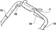
Fig. 2 A is the enlarged perspective of a part of the handle of back-pushed machine, shows the control device of Fig. 1;
Fig. 2 B is the end view of the machine of back-pushed shown in Fig. 1;
Fig. 3 A is the top cross-sectional view of the left part of control device shown in Fig. 1 in separation point position of one embodiment of the invention;
Fig. 3 B is the top cross-sectional view of the right side part of control device shown in Fig. 1 in separation point position of one embodiment of the invention;
Fig. 4 A is the top cross-sectional view of the left part of control device shown in Fig. 1 in bonding station of one embodiment of the invention;
Fig. 4 B is the top cross-sectional view of the right side part of control device shown in Fig. 1 in bonding station of one embodiment of the invention.
Embodiment
The present invention relates to operating control device and the method for the back-pushed power machine (walk-behind power machine) for controlling mower or other suitable type.On the one hand, for example the mower shown in Fig. 2 A and 2B or other power machine (label is PM) can be provided with control device.It will be appreciated that, the embodiment of apparatus and method disclosed herein is not limited to mower, because embodiments of the invention can be applicable to suitable power machine arbitrarily, the back-pushed power machine of self-improvement in particular, such as but not limited to: snowplough (snow blower), blow leaf machine (leaf blower), garden dust catcher (yard vacuum), tiller (tiller), trimmer (edgers), sower (seeder), trimmer (trimmer), inflator (aerator), fertilizer distributor (fertilizer), fork truck (palette truck), road roller (graders), means of transport (vehicle for transportation), pave the way and engineering machinery (pavement and construction machine) etc.
With example shown in Fig. 1,2A and 2B, proceed to describe, power machine PM can comprise any suitable structure of known to those skilled in the art or rear exploitation.In the exemplary embodiment, power machine PM can comprise power-driven system or assembly.As shown in Fig. 1 and 2 B, power-driven system can comprise suitable motor M and transmission device T such as electro-motor or internal combustion engine.In addition, power machine PM can comprise apparatus control parts MCC (seeing for example Fig. 2 B), for example band brake or sheet brake clutch.Dissimilar, the 26S Proteasome Structure and Function of the parts of above-mentioned power machine PM are known to those skilled in the art, therefore no longer launch to describe.
Power machine PM also can comprise housing, the board MD that for example mows, and mowing board MD can comprise front outside, rear outside, upper outside and lower inside.Motor M, apparatus control parts MCC and transmission device T can be arranged on mowing board MD upper (being for example mounted to the upper outside of mowing board MD), and suitable cutting element CE (for example one or more blades) can be set in the lower inside of mowing board MD.
Label is that 10 handle can link to the rear portion of mowing board MD by suitable method arbitrarily, and to be suitable for the comfortable angle of controlling and operating of operator, extends upward therefrom.In one embodiment, handle 10 can roughly take the shape of the letter U, and therefore can comprise the shank 12A, the 12B that open for first and second minutes combining by pars intermedia 14.In certain embodiments, pars intermedia 14 can be the two-piece type plastic components that can be assembled on shank 12A, 12B separately.
Power machine PM also can comprise controller, and described controller can for example have one or more control device, and described one or more control device can be mounted to handle 10, the wherein said control device control assembly MCC that can be used for operating machines.For example, as shown in Figure 2 A, control device 20A and 20B can be arranged on the pars intermedia 14 of handle 10, also can be installed in the pars intermedia 14 of handle 10, so that operator can easily touch. Control device 20A and 20B can be attached in the mode of separating on pars intermedia 14 pars intermedia 14.In addition, control device 20A and 20B can be arranged on two opposition sides (opposing sides) of disclosed distortion control device (twist control apparatus) in for example U.S. Patent application No.10/751801 (submission on January 5th, 2004), U.S. Patent application No.11/125843 (on May 10th, 2005 submits to and promulgates as U.S. Patent No. 7318309), U.S. Patent application No.11/925536 (submission on October 26th, 2007) and U.S. Patent application No.11/848294 (submission on August 31st, 2007).Yet control device 20A and 20B not must be used with this distortion control device is collaborative.
With reference to figure 3A~4B, control device 20A and 20B can comprise respectively actuator, for example actuator 22A, 22B, and actuator 22A, 22B are mounted to handle 10 in the mode can pivotable moving. Actuator 22A and 22B can be the long wedge shape that is mounted to handle 10 at pivoting point.Like this, actuator 22A and 22B can be substantially as the triggering type buttons on handle 10.Specifically, when actuator 22A and 22B are during in extended position, as shown in Fig. 3 A and 3B, apparatus control parts MCC can be in released state; And when actuator 22A and 22B are during in pressing position, as shown in Fig. 4 A and 4B, apparatus control parts MCC can be in engagement state.Therefore, the operator of power machine PM can, in the situation that not unclamping handle 10, press and discharge actuator 22 with the control assembly MCC that operates machines like a cork.This ease for use is obviously different from the operation of common pivotable handle (pivoting bail), and in the situation that pivotable is shaken hands, most of users must unclamp hand grip conventionally, with at least one hand, stretches to handle and shakes hands towards own pull-up.
In order further to improve the availability of control device 20, actuator 22A and 22B can be arranged to arbitrary form.For example, actuator 22A and 22B can be the single button that is positioned at pars intermedia 14. Actuator 22A and 22B can comprise the stock portion of roughly extending along the length of pars intermedia 14. Actuator 22A and 22B can be located so that actuator 22A is used as the left actuator of the left side of the pars intermedia 14 that is positioned at handle 10, and actuator 22B is used as the right actuator of the right side of the pars intermedia 14 that is positioned at handle 10.In this double-button structure, operator can select only to move left actuator 22A, only mobile right actuator 22B or move two actuators simultaneously, with the control assembly MCC that operates machines.Therefore, this structure can provide the very big flexibility of the preference that adapts to different operating person.
For the movement of actuator 22A and 22B is associated with the operation of apparatus control parts MCC, control device 20A and 20B also can comprise respectively can be at sliding cam 24A and the 24B of handle 10 interior movements.Continue with reference to figure 3A~4B, sliding cam 24A and 24B can be arranged in the pars intermedia 14 of handle 10, and slippage therein.Specifically, as shown in Fig. 3 A~4B, sliding cam 24A and 24B can be arranged on respectively track or slot (label is 18A and 18B) is upper, to control sliding cam 24A and the 24B moving direction in handle 10.
For example, sliding cam 24A, 24B can roughly be wedge shape, make the active force (for example, respectively via engagement lugs 28A, 28B) that actuator 22A, 22B apply cam surface 26A, 26B respectively along a direction can make respectively sliding cam 24A, 24B move along second direction.In a specific example, if actuator 22A, 22B abut against sliding cam 24A, 24B along the direction perpendicular to handle 10 respectively and move, the shape of cam surface 26A, 26B can be designed so that the active force applying is transformed into sliding cam 24A, 24B along the movement of the axial direction of handle 10.As mentioned above, sliding cam 24A, 24B can move along the slot 18A, the 18B that are formed in handle 10 respectively, further to control sliding cam 24A, 24B movement in the direction.
Horizontally slip cam 24A, 24B can be the individual components moving independently from one another, and also can connected with each otherly make the movement of a cam cause that two cams move together.For example, connector 32 can be set left sliding cam 24A is connected to right sliding cam 24B.Specifically, connector 32 can be at the cable of the pars intermedia 14 that extends through handle 10 between cam 24A and 24B that horizontally slips.At sliding cam by this way in joining situation, horizontally slip cam 24A, 24B respectively with respect to the movement of left and right actuator 22A, 22B can be designed to horizontally slip cam 24A, 24B both along equidirectional, move pars intermedia 14 is interior.Therefore, the movement of a cam can cause that another correspondingly moves.
Interconnecting of sliding cam 24A, 24B and apparatus control parts MCC can realize with the cable 30 that is connected to apparatus control parts MCC.Therefore, the movement of any in actuator 22A, 22B causes sliding cam 24A or 24B in the situation that of handle 10 interior movement, and the movement of sliding cam 24A or 24B can and then make again cable 30 move to engage with apparatus control parts MCC.In certain embodiments, cable 30 can be Bowden line (Bowden wire), and its at least a portion can be wrapped and extend through same sheath shaft.Cable 30 can be along the shank 12A separating or 12B location.Or cable 30 can be positioned at handle 10 (the shank 12A or the 12B that separate), not seen to improve aesthetic property by hiding cable 30, and prevent the actuating that is not intended to apparatus control parts MCC.
In some constructions, cable 30 can be connected to independently sliding cam 24A, 24B both, the movement that makes arbitrary cam be independent of another cam can make cable 30 move so that movement machine control assembly MCC.For example, or sliding cam 24A, 24B can be linked together (using connector 32) as mentioned above, and cable 30 is connected to one of cam.In this configuration, regardless of what press, be which actuator part (being left actuator 22A or right actuator 22B), cable 30 all can move.For example, as shown in Fig. 3 A~4B, cable 30 can be connected to left sliding cam 24A, and right sliding cam 24B can be connected to left sliding cam 24A via connector 32.In this structure, mobile left actuator 22A can make left sliding cam 24A move to pull cable 30, thereby operates machines control assembly MCC.Under contrast, mobile right actuator 22B can make right sliding cam 24B move, but the movement of right sliding cam 24B is not direct pull cable 30, but pulls connector 32, and then makes left sliding cam 24A move to pull cable 30.Therefore, to the movement of arbitrary actuator 22A or 22B, all can be used for controlling machine control assembly MCC, and only single line cable 30 need be set.
This for example following this situation that is beneficial to that disposes that both movements of sliding cam 24A, 24B are associated, operator determines the actuator 22A or the 22B that press to change (selecting to keep with another hand) this situation.In this case, the state of apparatus control parts MCC will can not change, because it is unimportant on earth which sliding cam to be moved to bonding station, as long as at least one in mobile sliding cam 24A and 24B is just passable.
No matter particular configuration how, sliding cam 24A, 24B and cam surface 26A, 26B can be designed so that the relatively little movement of actuator 22A, 22B just can make sliding cam 24A, 24B that relatively large movement occurs respectively.Like this, the operator's of power machine PM relatively little input just can make the movement of sliding cam 24A, 24B be enough to mobile cable 30 and activate apparatus control parts MCC.For example, sliding cam 24A and/or 24B and cam surface 26A and/or 26B can be designed so that respectively, by making actuator 22A and/or 22B for example, with respect to handle 10 pivotables approximately 5~15 degree (approximately 8 degree), actuator 22A and/or 22B are moved between separation point position and bonding station, be just enough to engage or separated machine control assembly MCC.
Can will be connected to apparatus control parts MCC or control device 20A, 20B such as biasing mechanisms such as spring element S.For example, as shown in Figure 2 B, biasing mechanism can be as can be for making the spring element S on engine brake that is positioned at of common handle system reset.Or biasing mechanism can be installed in handle 10, for example, as the Compress Spring being associated with control device 20A or 20B.In this alternative constructions, biasing mechanism can make corresponding sliding cam 24A or 24B return to separation point position, thereby discharges engine brake, and corresponding actuator 22A or 22B are pushed back.In any structure, biasing mechanism can be to being biased to released state by apparatus control parts MCC, to help to realize the security purpose of emergent control.Like this, if operator applies enough active forces, to abut against the cam surface 26 of sliding cam 24, do not press actuator 22A and/or 22B, biasing mechanism can start that apparatus control parts MCC is moved to released state.Yet, can be by actuator 22A, 22B, the design alternative of sliding cam 24A, 24B (comprising cam surface 26A, 26B) and/or biasing mechanism becomes only to need low confining force (being for example less than about 1.5kg) just can keep the activation to apparatus control parts MCC.
In the situation that not deviating from spirit of the present invention and principal character, can implement the present invention by other form.Therefore, it is exemplary that above-described embodiment is all considered in all respects, rather than restrictive.Although only described the present invention with some preferred embodiments, apparent other embodiment of those skilled in the art also belonged to category of the present invention.
Claims (14)
1. for controlling a control device for the apparatus control parts of back-pushed machine, this control device comprises:
Handle for back-pushed machine;
Sliding cam can move in described handle, and this sliding cam is configured for being operably connected with the apparatus control parts of described back-pushed machine; With
Actuator, is mounted to described handle movably, and this actuator engages with at least a portion of described sliding cam, so that the movement of described actuator causes described sliding cam, with respect to actuator, is moved;
Thus, described actuator can abut against sliding cam along a direction and move, so that described sliding cam moves along second direction, controls the apparatus control parts of described back-pushed machine.
2. device as claimed in claim 1, wherein, described sliding cam has cam surface, and the movement that described actuator abuts against described cam surface is moved described sliding cam in described handle with respect to actuator.
3. device as claimed in claim 2, wherein, described actuator comprises the engagement lugs moving for abutting against the cam surface of described sliding cam.
4. device as claimed in claim 1, wherein, described sliding cam is wedge shape.
5. device as claimed in claim 1, wherein, described actuator comprises left actuator and the right actuator of the respective end that is positioned at described handle.
6. device as claimed in claim 5, wherein:
Described sliding cam comprises left sliding cam and right sliding cam, described left sliding cam is corresponding with described left actuator, so that the movement of described left actuator is moved described left sliding cam in described handle, and described right sliding cam is corresponding with described right actuator, so that the movement of described right actuator is moved described right sliding cam in described handle; And
When described left sliding cam or described right sliding cam are moved, described apparatus control parts are controlled.
7. device as claimed in claim 1, wherein, described actuator is mounted to described handle pivotly.
8. device as claimed in claim 1, wherein, described actuator comprises at least one button being connected on described handle.
9. device as claimed in claim 1, wherein:
The cable that also comprises the apparatus control parts that are connected to described sliding cam and described back-pushed machine,
The movement of described sliding cam in described handle moved described cable, to control described apparatus control parts.
10. device as claimed in claim 9, wherein, described cable is positioned at described handle.
11. 1 kinds for controlling the control device of the apparatus control parts of back-pushed machine, and this control device comprises:
Handle for back-pushed machine;
Sliding cam can move in described handle, and this sliding cam has left sliding cam and right sliding cam, and described left sliding cam and described right sliding cam are configured for being operably connected with the apparatus control parts of described back-pushed machine separately;
Left actuator, is connected to described handle movably, and this left actuator engages with at least a portion of described left sliding cam, so that the movement of described left actuator causes described left sliding cam, with respect to left actuator, is moved; With
Right actuator, is connected to described handle movably, and this right actuator engages with at least a portion of described right sliding cam, so that causing described right sliding cam, the movement of described right actuator is moved with respect to right actuator,
Thus, described left actuator can abut against left sliding cam along a direction and move, so that described left sliding cam moves along second direction, controls the apparatus control parts of described back-pushed machine; And
Described right actuator can abut against right sliding cam along a direction and move, so that described right sliding cam moves along second direction, controls the apparatus control parts of described back-pushed machine.
12. devices as claimed in claim 11, wherein:
Described left sliding cam and described right sliding cam have cam surface separately;
The movement that described left actuator abuts against the cam surface of described left sliding cam is moved described left sliding cam in described handle with respect to left actuator; And
The movement that described right actuator abuts against the cam surface of described right sliding cam is moved described right sliding cam in described handle with respect to right actuator.
13. devices as claimed in claim 11, wherein:
At least one in described left sliding cam and described right sliding cam is connected with cable, and described cable is connected to the apparatus control parts of described back-pushed machine;
The movement of at least one in described left sliding cam and described right sliding cam is moved described cable, to control described apparatus control parts.
14. 1 kinds for controlling the method for the apparatus control parts of back-pushed machine, comprising:
The actuator that makes to be mounted to the handle of back-pushed machine abuts against along a direction sliding cam being contained in described handle and moves, and described sliding cam is configured for being operably connected with the apparatus control parts of described back-pushed machine,
Wherein, along a direction, abut against sliding cam movement actuator described actuator is engaged with at least a portion of described sliding cam, to move described sliding cam along second direction, make the apparatus control parts of described back-pushed machine controlled.
Applications Claiming Priority (2)
| Application Number | Priority Date | Filing Date | Title |
|---|---|---|---|
| US12/402,052 US7762050B1 (en) | 2009-03-11 | 2009-03-11 | Bail-free machine control devices and methods |
| US12/402,052 | 2009-03-11 |
Publications (2)
| Publication Number | Publication Date |
|---|---|
| CN101828470A CN101828470A (en) | 2010-09-15 |
| CN101828470B true CN101828470B (en) | 2014-03-12 |
Family
ID=42035775
Family Applications (1)
| Application Number | Title | Priority Date | Filing Date |
|---|---|---|---|
| CN201010125307.6A Expired - Fee Related CN101828470B (en) | 2009-03-11 | 2010-02-24 | Bail-free machine control devices and methods |
Country Status (5)
| Country | Link |
|---|---|
| US (1) | US7762050B1 (en) |
| EP (1) | EP2227937B1 (en) |
| CN (1) | CN101828470B (en) |
| AT (1) | ATE506846T1 (en) |
| DE (1) | DE602010000026D1 (en) |
Families Citing this family (10)
| Publication number | Priority date | Publication date | Assignee | Title |
|---|---|---|---|---|
| JP5758599B2 (en) * | 2010-08-25 | 2015-08-05 | 株式会社マキタ | Push lawn mower |
| EP2447967B1 (en) * | 2010-10-29 | 2015-12-23 | Robert Bosch GmbH | Improvements in or relating to electrically-powered garden apparatus |
| US9651138B2 (en) | 2011-09-30 | 2017-05-16 | Mtd Products Inc. | Speed control assembly for a self-propelled walk-behind lawn mower |
| US9696749B2 (en) * | 2013-05-24 | 2017-07-04 | Honda Motor Co., Ltd. | Control devices, systems, and methods for self-propelled machinery |
| US9470305B2 (en) * | 2014-01-24 | 2016-10-18 | Honda Motor Co., Ltd. | Variable speed control systems and methods for walk-behind working machines |
| US10486727B2 (en) * | 2016-09-20 | 2019-11-26 | 9875549 Canada Inc. | Wheelbarrow |
| JP2018088833A (en) * | 2016-11-30 | 2018-06-14 | 本田技研工業株式会社 | Electric work machine |
| AU2017412539B2 (en) | 2017-05-02 | 2020-04-30 | Nanjing Chervon Industry Co., Ltd. | Walk-behind self-propelled machine |
| US11528841B2 (en) | 2019-08-08 | 2022-12-20 | Honda Motor Co., Ltd. | Adjustable electric control handle for a lawn mower |
| US20230098509A1 (en) * | 2021-09-29 | 2023-03-30 | The Toro Company | Walk outdoor power equipment unit having handle mounted operational controls using compliant mechanisms |
Citations (3)
| Publication number | Priority date | Publication date | Assignee | Title |
|---|---|---|---|---|
| CN1299582A (en) * | 1999-12-10 | 2001-06-20 | 南京理工大学 | Linked operating-walking mower |
| CN2682551Y (en) * | 2004-02-16 | 2005-03-02 | 苏州太湖企业有限公司 | On-off control device for mower |
| CN201160377Y (en) * | 2008-01-29 | 2008-12-10 | 陈寅 | Switch of grass pulling machine |
Family Cites Families (18)
| Publication number | Priority date | Publication date | Assignee | Title |
|---|---|---|---|---|
| US3855763A (en) | 1972-09-15 | 1974-12-24 | R Dunton | Self-propelled rotary lawn mower |
| US4028804A (en) * | 1976-04-19 | 1977-06-14 | Mcculloch Corporation | Chain saw with throttle control |
| US4306405A (en) | 1980-08-07 | 1981-12-22 | Roper Corporation | Drive assembly for rotary mower or the like |
| US4413466A (en) * | 1982-01-01 | 1983-11-08 | Conchemco, Incorporated | Control assembly for blade clutch unit |
| JPS58205416A (en) * | 1982-05-25 | 1983-11-30 | スタ−テング工業株式会社 | Operation lever for mower |
| US4466308A (en) * | 1982-06-16 | 1984-08-21 | Conchemco, Incorporated | Control assembly for lawnmower having electrically started engine |
| US4704847A (en) | 1985-12-09 | 1987-11-10 | Western International, Inc. | Control mechanism for walk-behind mower |
| US4707921A (en) * | 1986-08-04 | 1987-11-24 | Marvin Glass & Associates | Extension handle for a handheld electrically powered tool |
| US5826667A (en) * | 1993-06-09 | 1998-10-27 | Notaras; John Arthur | Lawn edger |
| JP3237997B2 (en) * | 1994-04-25 | 2001-12-10 | 株式会社共立 | Safety devices for throttles for internal combustion engines |
| JP3529199B2 (en) | 1995-08-04 | 2004-05-24 | 株式会社共立 | Hand lever device |
| DE19621729B4 (en) * | 1996-05-29 | 2007-10-25 | Starting Industrial Co., Ltd. | Throttle device for a motor |
| JP3850954B2 (en) * | 1997-06-27 | 2006-11-29 | 本田技研工業株式会社 | Operation machine control lever device |
| GB9804796D0 (en) * | 1998-03-06 | 1998-04-29 | Black & Decker Inc | Clutch mechanism for a chain saw |
| US6904740B2 (en) * | 2003-02-11 | 2005-06-14 | Textron Inc. | Articulating handle for a walk-behind mower |
| US7318309B2 (en) | 2004-01-05 | 2008-01-15 | Honda Motor Co., Ltd | Variable speed transmission twist control apparatuses and methods for self-propelled mowing machine |
| JP4452206B2 (en) * | 2005-04-05 | 2010-04-21 | 川崎重工業株式会社 | Engine operating device for portable work machine |
| WO2010030281A1 (en) | 2008-09-12 | 2010-03-18 | Husqvarna U.S. Holding, Inc. | Mower with adjustable hand grips and partially enclosed operator present switch |
-
2009
- 2009-03-11 US US12/402,052 patent/US7762050B1/en not_active Expired - Fee Related
-
2010
- 2010-02-10 EP EP10153128A patent/EP2227937B1/en active Active
- 2010-02-10 DE DE602010000026T patent/DE602010000026D1/en active Active
- 2010-02-10 AT AT10153128T patent/ATE506846T1/en not_active IP Right Cessation
- 2010-02-24 CN CN201010125307.6A patent/CN101828470B/en not_active Expired - Fee Related
Patent Citations (3)
| Publication number | Priority date | Publication date | Assignee | Title |
|---|---|---|---|---|
| CN1299582A (en) * | 1999-12-10 | 2001-06-20 | 南京理工大学 | Linked operating-walking mower |
| CN2682551Y (en) * | 2004-02-16 | 2005-03-02 | 苏州太湖企业有限公司 | On-off control device for mower |
| CN201160377Y (en) * | 2008-01-29 | 2008-12-10 | 陈寅 | Switch of grass pulling machine |
Also Published As
| Publication number | Publication date |
|---|---|
| EP2227937B1 (en) | 2011-04-27 |
| CN101828470A (en) | 2010-09-15 |
| EP2227937A1 (en) | 2010-09-15 |
| US7762050B1 (en) | 2010-07-27 |
| DE602010000026D1 (en) | 2011-06-09 |
| ATE506846T1 (en) | 2011-05-15 |
Similar Documents
| Publication | Publication Date | Title |
|---|---|---|
| CN101828470B (en) | Bail-free machine control devices and methods | |
| EP2777377B1 (en) | Door lift and handle for walk behind mower | |
| EP1295521B1 (en) | Working machine and machine for mowing and soil working | |
| US20020153179A1 (en) | Walk-behind, self-propelled working machine | |
| KR101122420B1 (en) | Lawn mower | |
| CN107529721B (en) | Cutting height adjusting assembly of mower | |
| EP1597958A1 (en) | Walk behind powered apparatus with operator presence system | |
| EP2903849B1 (en) | Pto control system | |
| CN105379568B (en) | Switching and braking system for a handheld garden device | |
| US4723933A (en) | PTO linear control latch | |
| AU2011101131A4 (en) | Hedge Trimmer And Switch Device Thereof | |
| EP2757868B1 (en) | Lawn care vehicle with cutting deck lifting pedal | |
| US7891161B2 (en) | Two-step bail apparatuses and methods | |
| EP2770813A1 (en) | A folding arrangement for a handle assembly of walk-behind power tool, a handle assembly and a walk-behind power tool comprising such an arrangement | |
| DE4421746A1 (en) | Electrically-operated hedge cutters with 2-handed safety control | |
| WO2013122518A1 (en) | Brake assembly for power-driven hand-held cutting device | |
| EP3506730B1 (en) | A walk behind working machine | |
| CN220255118U (en) | User interface for a power tool and mower comprising a user interface | |
| JPH056733Y2 (en) | ||
| AU627482B2 (en) | Drive assembly having dual neutrality control | |
| JPS6345162Y2 (en) | ||
| US8695314B2 (en) | Two-way action cable control assemblies, systems and methods | |
| EP2623402B1 (en) | Operating lever unit for walk-behind working machine | |
| KR20150054336A (en) | Wood crusher | |
| WO2016207833A1 (en) | Drive control, walk behind outdoor powertool |
Legal Events
| Date | Code | Title | Description |
|---|---|---|---|
| C06 | Publication | ||
| PB01 | Publication | ||
| C10 | Entry into substantive examination | ||
| SE01 | Entry into force of request for substantive examination | ||
| GR01 | Patent grant | ||
| GR01 | Patent grant | ||
| CF01 | Termination of patent right due to non-payment of annual fee |
Granted publication date: 20140312 Termination date: 20180224 |
|
| CF01 | Termination of patent right due to non-payment of annual fee |