CN101806247B - Optimization of low-btu fuel-fired combined-cycle power plant by performance heating - Google Patents
Optimization of low-btu fuel-fired combined-cycle power plant by performance heating Download PDFInfo
- Publication number
- CN101806247B CN101806247B CN2010101271356A CN201010127135A CN101806247B CN 101806247 B CN101806247 B CN 101806247B CN 2010101271356 A CN2010101271356 A CN 2010101271356A CN 201010127135 A CN201010127135 A CN 201010127135A CN 101806247 B CN101806247 B CN 101806247B
- Authority
- CN
- China
- Prior art keywords
- gas
- blast furnace
- turbine
- heating unit
- power plant
- Prior art date
- Legal status (The legal status is an assumption and is not a legal conclusion. Google has not performed a legal analysis and makes no representation as to the accuracy of the status listed.)
- Expired - Fee Related
Links
Images

Classifications
-
- F—MECHANICAL ENGINEERING; LIGHTING; HEATING; WEAPONS; BLASTING
- F02—COMBUSTION ENGINES; HOT-GAS OR COMBUSTION-PRODUCT ENGINE PLANTS
- F02C—GAS-TURBINE PLANTS; AIR INTAKES FOR JET-PROPULSION PLANTS; CONTROLLING FUEL SUPPLY IN AIR-BREATHING JET-PROPULSION PLANTS
- F02C7/00—Features, components parts, details or accessories, not provided for in, or of interest apart form groups F02C1/00 - F02C6/00; Air intakes for jet-propulsion plants
- F02C7/22—Fuel supply systems
- F02C7/224—Heating fuel before feeding to the burner
-
- F—MECHANICAL ENGINEERING; LIGHTING; HEATING; WEAPONS; BLASTING
- F01—MACHINES OR ENGINES IN GENERAL; ENGINE PLANTS IN GENERAL; STEAM ENGINES
- F01K—STEAM ENGINE PLANTS; STEAM ACCUMULATORS; ENGINE PLANTS NOT OTHERWISE PROVIDED FOR; ENGINES USING SPECIAL WORKING FLUIDS OR CYCLES
- F01K23/00—Plants characterised by more than one engine delivering power external to the plant, the engines being driven by different fluids
- F01K23/02—Plants characterised by more than one engine delivering power external to the plant, the engines being driven by different fluids the engine cycles being thermally coupled
- F01K23/06—Plants characterised by more than one engine delivering power external to the plant, the engines being driven by different fluids the engine cycles being thermally coupled combustion heat from one cycle heating the fluid in another cycle
- F01K23/10—Plants characterised by more than one engine delivering power external to the plant, the engines being driven by different fluids the engine cycles being thermally coupled combustion heat from one cycle heating the fluid in another cycle with exhaust fluid of one cycle heating the fluid in another cycle
-
- F—MECHANICAL ENGINEERING; LIGHTING; HEATING; WEAPONS; BLASTING
- F02—COMBUSTION ENGINES; HOT-GAS OR COMBUSTION-PRODUCT ENGINE PLANTS
- F02C—GAS-TURBINE PLANTS; AIR INTAKES FOR JET-PROPULSION PLANTS; CONTROLLING FUEL SUPPLY IN AIR-BREATHING JET-PROPULSION PLANTS
- F02C3/00—Gas-turbine plants characterised by the use of combustion products as the working fluid
- F02C3/20—Gas-turbine plants characterised by the use of combustion products as the working fluid using a special fuel, oxidant, or dilution fluid to generate the combustion products
-
- F—MECHANICAL ENGINEERING; LIGHTING; HEATING; WEAPONS; BLASTING
- F02—COMBUSTION ENGINES; HOT-GAS OR COMBUSTION-PRODUCT ENGINE PLANTS
- F02C—GAS-TURBINE PLANTS; AIR INTAKES FOR JET-PROPULSION PLANTS; CONTROLLING FUEL SUPPLY IN AIR-BREATHING JET-PROPULSION PLANTS
- F02C6/00—Plural gas-turbine plants; Combinations of gas-turbine plants with other apparatus; Adaptations of gas- turbine plants for special use
- F02C6/04—Gas-turbine plants providing heated or pressurised working fluid for other apparatus, e.g. without mechanical power output
- F02C6/06—Gas-turbine plants providing heated or pressurised working fluid for other apparatus, e.g. without mechanical power output providing compressed gas
- F02C6/08—Gas-turbine plants providing heated or pressurised working fluid for other apparatus, e.g. without mechanical power output providing compressed gas the gas being bled from the gas-turbine compressor
-
- F—MECHANICAL ENGINEERING; LIGHTING; HEATING; WEAPONS; BLASTING
- F02—COMBUSTION ENGINES; HOT-GAS OR COMBUSTION-PRODUCT ENGINE PLANTS
- F02C—GAS-TURBINE PLANTS; AIR INTAKES FOR JET-PROPULSION PLANTS; CONTROLLING FUEL SUPPLY IN AIR-BREATHING JET-PROPULSION PLANTS
- F02C6/00—Plural gas-turbine plants; Combinations of gas-turbine plants with other apparatus; Adaptations of gas- turbine plants for special use
- F02C6/18—Plural gas-turbine plants; Combinations of gas-turbine plants with other apparatus; Adaptations of gas- turbine plants for special use using the waste heat of gas-turbine plants outside the plants themselves, e.g. gas-turbine power heat plants
-
- F—MECHANICAL ENGINEERING; LIGHTING; HEATING; WEAPONS; BLASTING
- F22—STEAM GENERATION
- F22B—METHODS OF STEAM GENERATION; STEAM BOILERS
- F22B1/00—Methods of steam generation characterised by form of heating method
- F22B1/02—Methods of steam generation characterised by form of heating method by exploitation of the heat content of hot heat carriers
- F22B1/18—Methods of steam generation characterised by form of heating method by exploitation of the heat content of hot heat carriers the heat carrier being a hot gas, e.g. waste gas such as exhaust gas of internal-combustion engines
- F22B1/1807—Methods of steam generation characterised by form of heating method by exploitation of the heat content of hot heat carriers the heat carrier being a hot gas, e.g. waste gas such as exhaust gas of internal-combustion engines using the exhaust gases of combustion engines
- F22B1/1815—Methods of steam generation characterised by form of heating method by exploitation of the heat content of hot heat carriers the heat carrier being a hot gas, e.g. waste gas such as exhaust gas of internal-combustion engines using the exhaust gases of combustion engines using the exhaust gases of gas-turbines
-
- F—MECHANICAL ENGINEERING; LIGHTING; HEATING; WEAPONS; BLASTING
- F22—STEAM GENERATION
- F22B—METHODS OF STEAM GENERATION; STEAM BOILERS
- F22B1/00—Methods of steam generation characterised by form of heating method
- F22B1/02—Methods of steam generation characterised by form of heating method by exploitation of the heat content of hot heat carriers
- F22B1/18—Methods of steam generation characterised by form of heating method by exploitation of the heat content of hot heat carriers the heat carrier being a hot gas, e.g. waste gas such as exhaust gas of internal-combustion engines
- F22B1/1838—Methods of steam generation characterised by form of heating method by exploitation of the heat content of hot heat carriers the heat carrier being a hot gas, e.g. waste gas such as exhaust gas of internal-combustion engines the hot gas being under a high pressure, e.g. in chemical installations
- F22B1/1846—Methods of steam generation characterised by form of heating method by exploitation of the heat content of hot heat carriers the heat carrier being a hot gas, e.g. waste gas such as exhaust gas of internal-combustion engines the hot gas being under a high pressure, e.g. in chemical installations the hot gas being loaded with particles, e.g. waste heat boilers after a coal gasification plant
-
- Y—GENERAL TAGGING OF NEW TECHNOLOGICAL DEVELOPMENTS; GENERAL TAGGING OF CROSS-SECTIONAL TECHNOLOGIES SPANNING OVER SEVERAL SECTIONS OF THE IPC; TECHNICAL SUBJECTS COVERED BY FORMER USPC CROSS-REFERENCE ART COLLECTIONS [XRACs] AND DIGESTS
- Y02—TECHNOLOGIES OR APPLICATIONS FOR MITIGATION OR ADAPTATION AGAINST CLIMATE CHANGE
- Y02E—REDUCTION OF GREENHOUSE GAS [GHG] EMISSIONS, RELATED TO ENERGY GENERATION, TRANSMISSION OR DISTRIBUTION
- Y02E20/00—Combustion technologies with mitigation potential
- Y02E20/14—Combined heat and power generation [CHP]
-
- Y—GENERAL TAGGING OF NEW TECHNOLOGICAL DEVELOPMENTS; GENERAL TAGGING OF CROSS-SECTIONAL TECHNOLOGIES SPANNING OVER SEVERAL SECTIONS OF THE IPC; TECHNICAL SUBJECTS COVERED BY FORMER USPC CROSS-REFERENCE ART COLLECTIONS [XRACs] AND DIGESTS
- Y02—TECHNOLOGIES OR APPLICATIONS FOR MITIGATION OR ADAPTATION AGAINST CLIMATE CHANGE
- Y02E—REDUCTION OF GREENHOUSE GAS [GHG] EMISSIONS, RELATED TO ENERGY GENERATION, TRANSMISSION OR DISTRIBUTION
- Y02E20/00—Combustion technologies with mitigation potential
- Y02E20/16—Combined cycle power plant [CCPP], or combined cycle gas turbine [CCGT]
Abstract
Disclosed is an optimized approach of using bleed-off of compressed air flow from a gas turbine compressor (240) in a combined-cycle power plant (200) and performance heating to augment plant performance. In one embodiment, a diverted portion of a by-product off gas and the bleed-off of compressed air flow are fired heated to produce a high temperature flue gas (285) that is used to performance heat a pressurized mixture of fuel prior to being supplied to the gas turbine combustor (245).
Description
Technical field
The present invention relates generally to the combined cycle power plant that uses low BTU fuel, and more particularly, relate to by fuel being carried out performance heating (performance heating) and optimize the fuel that is supplied to gas turbine and improve efficient and power stage in combined cycle power plant.Background technique
The combined cycle power plant that uses low BTU fuel is the combined cycle power plant of such a type: implemented this combined cycle power plant, in order to compare efficient and the lower discharging that provides higher with traditional boiler power generating equipment.Low-BTU gas such as blast furnace gas (BFG) and oven gas (COG), is usually produced in steel works during the pig iron as the by product of the iron ore melt in coke burning and blast furnace and is produced.In the power generating equipment scene, reclaim low BTU gas, and used as the fuel in the gas turbine combined cycle power plant solution, the gas turbine combined cycle power plant solution can produce for steel works and be sold to both electric energy of public electric wire net.Summary of the invention
In one aspect of the invention, provide a kind of combined cycle power plant based on low BTU fuel.This combined cycle power plant comprises the gas mixed cell that mixes by product waste gas.Be connected to fuel gas compressors on the gas mixed cell to the pressurization of the mixture of by product waste gas.Gas turbine is fueled by the pressurised mixt from the by product waste gas of fuel gas compressor.Gas turbine comprises: compressor; Burner, this burner receive from the air of compressor and from the pressurised mixt of the by product waste gas of fuel gas compressors, so that their burnings; And turbine, this turbine makes by from the air of compressor and the hot gas expander that produces from the burning of the pressurised mixt of the by product waste gas of fuel gas compressors.This combined cycle power plant further comprises combustion heating (fired heating) unit, and this combustion heating unit receives the part that turns to of by product waste gas and from the pressurized air stream effulent of gas-turbine compressor, so that they burn.The burning of the part that turns to of by product waste gas and pressurized air stream effulent in the combustion heating unit produces high-temperature flue gas.Combined cycle power plant also comprises the performance heating unit, before the pressurised mixt from the by product waste gas of fuel gas compressors entered gas turbine burner, this performance heating unit utilization was heated this from the pressurised mixt of the by product waste gas of fuel gas compressors by the high-temperature flue gas that the combustion heating unit produces.
In another aspect of this invention, provide a kind of combined cycle power plant that uses blast furnace gas.Of the present invention aspect this in, blast furnace gas combined cycle power plant comprises the gas mixed cell of mixing drum wind furnace gas and oven gas.Be connected to fuel gas compressors on the gas mixed cell to the pressurization of the mixture of blast furnace gas and oven gas.Gas turbine is by fueling from the blast furnace gas of fuel gas compressor and the pressurised mixt of oven gas.Gas turbine comprises: compressor; Burner, it receives from the air of compressor with from the blast furnace gas of fuel gas compressors and the pressurised mixt of oven gas, so that they burn; And turbine, turbine makes by from the air of compressor and the hot gas expander that produces from the burning of the pressurised mixt of the blast furnace gas of fuel gas compressors and oven gas.Blast furnace gas combined cycle power plant further comprises the combustion heating unit, and this combustion heating unit receives the part that turns to of blast furnace gas and from the pressurized air stream effulent of gas-turbine compressor, so that they burn.The burning of the part that turns to of blast furnace gas and pressurized air stream effulent in the combustion heating unit produces high-temperature flue gas.Blast furnace gas combined cycle power plant also comprises the performance heating unit, before the pressurised mixt from the blast furnace gas of fuel gas compressors and oven gas entered gas turbine burner, the utilization of performance heating unit was heated this from the blast furnace gas of fuel gas compressors and the pressurised mixt of oven gas by the high-temperature flue gas that the combustion heating unit produces.
In a third aspect of the present invention, have that a kind of raising uses in blast furnace gas combined cycle power plant low-method of the temperature of BTU fuel.Of the present invention aspect this in, the method comprises: blast furnace gas is mixed with oven gas; Mixture pressurization to blast furnace gas and oven gas; Carry out combustion heating to the part that turns to of blast furnace gas with from the pressurized air stream effulent of gas-turbine compressor, so that their burnings; And before being supplied to gas turbine burner, utilize the high-temperature flue gas that produced by the part that turns to of blast furnace gas and the effulent burning of pressurized air stream to carry out the performance heating to the pressurised mixt of blast furnace gas and oven gas.Description of drawings
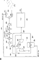
Fig. 1 is the schematic diagram of the traditional combined cycle power plant that uses BFG; And
Fig. 2 is the schematic diagram of the combined cycle power plant of the BFG of using according to an embodiment of the invention.Embodiment
Referring to accompanying drawing, Fig. 1 has shown the schematic diagram of traditional combined cycle power plant that uses BFG 100.As shown in fig. 1, the by product waste gas that comprises BFG and COG is supplied to gas mixed cell 105 from steel works 110.Although not shown in Fig. 1, other by product waste gas (such as Linz Donawitz gas (LDG) and COREX gas) from steel works 110 dischargings can be used as low-BTU fuel.Usually, be supplied to the amount of BFG of gas mixed cell 105 far away more than the amount of COG.For example, mixed cell 105 can receive the BFG of about 250pps and the COG of about 10pps from steel works 110.Usually be in low pressure from the BFG of steel works 110 supply and the amount of COG, and the mixture of the BFG that is therefore produced by gas mixed cell 105 and COG is in the low pressure of about 15.5psia substantially.This gaseous mixture need to be raised to higher pressure, so that with the fuel that acts on gas turbine burner.
The combined cycle power plant 100 centrifugal fuel gas compressors 115 of use that use BFG are brought up to about 300psia with the pressure of the gaseous mixture of BFG and COG.As shown in fig. 1, fuel gas compressors 115 is multi-stage fuel gas compressors, and it comprises the first fuel gas compressors (FGC1) 120 and the second fuel gas compressors (FGC2) 125 in this embodiment.Intercooler unit 130 is between FGC1 120 and FGC2 125, in order to improve the efficient of fuel gas compressors 115.
The emitted exhaust products that heat recovery steam generator (HRSG) 165 receives from turbine 150 is in order to reclaim used heat from this emitted exhaust products.The heat that reclaims from emitted exhaust products is passed in refuse/steam HRSG 165, is supplied to the steam turbine (not shown) to drive the steam of generator (not shown) in order to produce.Cooled gas from HRSG165 is discharged in atmosphere by chimney.Those skilled in the art will recognize that, this part of BFG combined cycle power plant 100 can have other member (for example condenser, water pipe etc.), but for the ease of the signal embodiments of the invention with its omission.Similarly, those skilled in the art will recognize that, the part relevant to gas turbine 135 that uses the combined cycle power plant 100 of BFG can have other member (for example gas turbine powered generator) that does not show, but omitted these members for the ease of the signal embodiments of the invention.
As determined in this paper, as to exist some to be associated with the operation of the combined cycle power plant 100 that uses BFG shortcoming.For example, because the gaseous mixture of BFG and COG has low LHV, so need the fuel of huge amount to obtain combustion temperature in the burner 145 of gas turbine 135.The result that needs a large amount of fuel is that fuel gas compressors 115 must be compressed more this low LHV fuel.As a result, fuel gas compressors 115 has a large amount of power consumpitons, and this can reduce combined cycle and only export.Another shortcoming that is associated with the operation of the combined cycle power plant 100 that uses BFG is to utilize the mode of OBB.Especially, found OBB is discharged to from compressor 140 overall efficiency of the exhaust 160 meeting reduction combined cycle power plants 100 of turbine 150 herein.
Fig. 2 has optimized above mentioned shortcoming in order to raise the efficiency schematic diagram with the combined cycle power plant that uses BFG 200 of power stage.In Fig. 2 to Fig. 1 in the similar member of member that uses be endowed similar reference element, the reference element front of just using in Fig. 2 has added label 2.Be similar to Fig. 1, Fig. 2 only shown the combined cycle power plant 200 that uses BFG, set forth its operation and relate to the necessary part of embodiment as herein described of its optimization.
As shown in Figure 2, BFG gas diverter 270 turns to the part of this BFG at the BFG from steel works 210 in gas mixed cell 205 with before COG mixes.In one embodiment, BFG gas diverter 270 turns to the BFG of about 21.5pps of the temperature of pressure with about 15.5psia and about 104 ℉ (40 ℃).The part that turns to of BFG is by reference element 275 expressions.
As shown in herein, efficient and the power stage of Fig. 2 are improved, because performance heating unit 290 is used to the pressurised mixt that the high-temperature flue gas 285 of spontaneous combustion heating unit 280 has preheated BFG and COG.This character representation needs less fuel to obtain combustion temperature by fuel gas compressors 215 in the burner 245 of gas turbine 255.As a result, reduced the power consumpiton of fuel gas compressors 215, this can change into the clean output of the combined cycle power plant 200 that uses BFG and the raising of net efficiency.Equally, because reduced the fuel flow requirement of fuel gas compressors 215, so relax to some extent in compressor 240 stall margins, place, this can change into discharges less OBB (that is, reducing about 30%).As a result, this feature also helps to improve the overall efficiency of the combined cycle power plant 200 that uses BFG.Therefore, implement the included design of this paper the clean combined cycle output growth of approximately+1.44MW and the efficiency propagation of approximately+0.37% will be provided.
Although shown especially and described the disclosure in conjunction with preferred embodiment of the present disclosure, will be appreciated that, those skilled in the art will envision that variants and modifications.Therefore, will be appreciated that the appending claims intention covers all such modifications and the change that drops in practicalness of the present disclosure.
Claims (10)
1. combined cycle power plant based on low BTU fuel comprises:
Mix the gas mixed cell of by product waste gas, wherein, described by product waste gas comprises blast furnace gas and oven gas;
Be connected on described gas mixed cell, to the fuel gas compressors of the mixture pressurization of by product waste gas;
By the gas turbine that the pressurised mixt from the by product waste gas of described fuel gas compressors fuels, described gas turbine comprises: compressor; Burner, described burner receive from the air of described compressor and from the pressurised mixt of the by product waste gas of described fuel gas compressors, so that this air and the burning of this pressurised mixt; And turbine, described turbine makes by from the air of described compressor and the hot gas expander that produces from the burning of the pressurised mixt of the described by product waste gas of described fuel gas compressors;
The combustion heating unit, described combustion heating unit receives the part that turns to of described by product waste gas and from the pressurized air stream effulent of described gas-turbine compressor, so that this part that turns to and the burning of this effulent, the part that turns to of the described by product waste gas that is wherein received by described combustion heating unit comprises the part of described blast furnace gas, and the burning in described combustion heating unit of the part that turns to of described by product waste gas and described pressurized air stream effulent produces high-temperature flue gas; And
The performance heating unit, before the pressurised mixt from the described by product waste gas of described fuel gas compressors enters described gas turbine burner, the utilization of described performance heating unit is heated this from the pressurised mixt of the described by product waste gas of described fuel gas compressors by the described high-temperature flue gas that described combustion heating unit produces, wherein, mix with exhaust from described gas turbine from the exhaust of described performance heating unit.
2. combined cycle power plant according to claim 1, is characterized in that, described fuel gas compressors comprises the multi-stage fuel gas compressor, and wherein at least one intercooler unit is between at different levels.
3. combined cycle power plant according to claim 1, is characterized in that, described performance heating unit comprises heat exchanger.
4. combined cycle power plant according to claim 1, is characterized in that, further comprises the heat recovery steam generator that receives from the exhaust of described gas turbine.
5. combined cycle power plant that uses blast furnace gas comprises:
The gas mixed cell that blast furnace gas is mixed with oven gas;
Be connected on described gas mixed cell, to the fuel gas compressors of the mixture pressurization of described blast furnace gas and oven gas;
By the gas turbine that the pressurised mixt from the described blast furnace gas of described fuel gas compressors and oven gas fuels, described gas turbine comprises: compressor; Burner, described burner receives from the air of described compressor with from the described blast furnace gas of described fuel gas compressors and the pressurised mixt of oven gas, so that this air and the burning of this pressurised mixt; And turbine, described turbine makes the hot gas expander that produces by from the air of described compressor and burning from the pressurised mixt of the described blast furnace gas of described fuel gas compressors and oven gas;
The combustion heating unit, described combustion heating unit receives the part that turns to of described blast furnace gas and from the pressurized air stream effulent of described gas-turbine compressor, so that this part that turns to and the burning of this effulent, the burning in described combustion heating unit of the part that turns to of described blast furnace gas and described pressurized air stream effulent produces high-temperature flue gas; And
The performance heating unit, before the pressurised mixt from the described blast furnace gas of described fuel gas compressors and oven gas enters described gas turbine burner, the utilization of described performance heating unit is heated from the described blast furnace gas of described fuel gas compressors and the pressurised mixt of oven gas by the described high-temperature flue gas that described combustion heating unit produces, wherein, mix with exhaust from described gas turbine from the exhaust of described performance heating unit.
6. blast furnace gas combined cycle power plant according to claim 5, is characterized in that, described fuel gas compressors comprises the multi-stage fuel gas compressor, and wherein at least one intercooler unit is between at different levels.
7. blast furnace gas combined cycle power plant according to claim 5, is characterized in that, described performance heating unit comprises heat exchanger.
8. blast furnace gas combined cycle power plant according to claim 5, is characterized in that, described blast furnace gas combined cycle power plant further comprises the heat recovery steam generator that receives from the exhaust of described gas turbine.
9. the method for the temperature of a raising is used in blast furnace gas combined cycle power plant low-BTU fuel comprises:
Mixing drum wind furnace gas and oven gas;
Mixture pressurization to described blast furnace gas and oven gas;
Carry out combustion heating to the part that turns to of described blast furnace gas with from the pressurized air stream effulent of gas-turbine compressor, so that this part that turns to and the burning of this effulent; And
Before the pressurised mixt with described blast furnace gas and oven gas is fed to gas turbine burner, the high-temperature flue gas that utilization is produced by the burning of the part that turns to of described blast furnace gas and described pressurized air stream effulent carries out the performance heating to the pressurised mixt of described blast furnace gas and oven gas, and makes from the exhaust of described performance heating and mix with exhaust from described gas turbine.
10. method according to claim 9, is characterized in that, described method further comprises the exhaust from gas turbine is supplied to heat recovery steam generator.
Applications Claiming Priority (3)
| Application Number | Priority Date | Filing Date | Title |
|---|---|---|---|
| US12/369,180 US8117821B2 (en) | 2009-02-11 | 2009-02-11 | Optimization of low-BTU fuel-fired combined-cycle power plant by performance heating |
| US12/369180 | 2009-02-11 | ||
| US12/369,180 | 2009-02-11 |
Publications (2)
| Publication Number | Publication Date |
|---|---|
| CN101806247A CN101806247A (en) | 2010-08-18 |
| CN101806247B true CN101806247B (en) | 2013-06-19 |
Family
ID=41718827
Family Applications (1)
| Application Number | Title | Priority Date | Filing Date |
|---|---|---|---|
| CN2010101271356A Expired - Fee Related CN101806247B (en) | 2009-02-11 | 2010-02-11 | Optimization of low-btu fuel-fired combined-cycle power plant by performance heating |
Country Status (4)
| Country | Link |
|---|---|
| US (1) | US8117821B2 (en) |
| EP (1) | EP2218888A2 (en) |
| JP (1) | JP5101642B2 (en) |
| CN (1) | CN101806247B (en) |
Families Citing this family (12)
| Publication number | Priority date | Publication date | Assignee | Title |
|---|---|---|---|---|
| AU2012327118B2 (en) * | 2011-10-17 | 2016-04-14 | Kawasaki Jukogyo Kabushiki Kaisha | Lean fuel intake gas turbine |
| US8677729B2 (en) * | 2011-10-25 | 2014-03-25 | General Electric Company | System for heating a fuel |
| US9377202B2 (en) | 2013-03-15 | 2016-06-28 | General Electric Company | System and method for fuel blending and control in gas turbines |
| US9382850B2 (en) | 2013-03-21 | 2016-07-05 | General Electric Company | System and method for controlled fuel blending in gas turbines |
| CN104075344B (en) | 2013-03-25 | 2016-07-06 | 通用电气公司 | Start and operate fuel nozzle system and the method for gas turbine with low calorie fuels |
| CN103670712B (en) * | 2013-12-13 | 2017-01-04 | 中国大唐集团科学技术研究院有限公司 | A kind of gas turbine generating system |
| US20160273396A1 (en) * | 2015-03-19 | 2016-09-22 | General Electric Company | Power generation system having compressor creating excess air flow and heat exchanger therefor |
| US9828887B2 (en) * | 2015-03-19 | 2017-11-28 | General Electric Company | Power generation system having compressor creating excess air flow and turbo-expander to increase turbine exhaust gas mass flow |
| CN107869391A (en) * | 2016-09-23 | 2018-04-03 | 熵零技术逻辑工程院集团股份有限公司 | A kind of zero-emission thermo-motor |
| EA037782B1 (en) * | 2017-03-20 | 2021-05-20 | Ланцатек, Инк. | Process and system for product recovery and cell recycle |
| JP7067349B2 (en) * | 2018-08-02 | 2022-05-16 | 三浦工業株式会社 | By-product gas utilization system |
| EP3921433A4 (en) | 2019-02-08 | 2022-11-23 | Lanzatech, Inc. | Process for recovering close boiling products |
Citations (5)
| Publication number | Priority date | Publication date | Assignee | Title |
|---|---|---|---|---|
| US4202168A (en) * | 1977-04-28 | 1980-05-13 | Gulf Research & Development Company | Method for the recovery of power from LHV gas |
| US6313544B1 (en) * | 1997-09-19 | 2001-11-06 | Solo Energy Corporation | Self-contained energy center for producing mechanical, electrical, and heat energy |
| CN1475663A (en) * | 1997-09-18 | 2004-02-18 | 东芝株式会社 | Gas turbine device |
| CN1671956A (en) * | 2002-07-25 | 2005-09-21 | 西门子公司 | System for cooling cooling air in a gas turbine, and method for cooling cooling air |
| CN101270689A (en) * | 2008-04-30 | 2008-09-24 | 杭州杭氧透平机械有限公司 | Energy conversion and recovering method of coal gasification supercharging association circulating power generation system |
Family Cites Families (12)
| Publication number | Priority date | Publication date | Assignee | Title |
|---|---|---|---|---|
| US2925712A (en) * | 1952-12-12 | 1960-02-23 | Rolls Royce | Aircraft fuel system with fuel heating means |
| US5392595A (en) * | 1993-08-06 | 1995-02-28 | United Technologies Corporation | Endothermic fuel energy management system |
| US6216441B1 (en) | 1997-09-17 | 2001-04-17 | General Electric Co | Removal of inert gases from process gases prior to compression in a gas turbine or combined cycle power plant |
| US6065280A (en) | 1998-04-08 | 2000-05-23 | General Electric Co. | Method of heating gas turbine fuel in a combined cycle power plant using multi-component flow mixtures |
| DE19952885A1 (en) * | 1999-11-03 | 2001-05-10 | Alstom Power Schweiz Ag Baden | Process and operation of a power plant |
| US6442941B1 (en) | 2000-09-11 | 2002-09-03 | General Electric Company | Compressor discharge bleed air circuit in gas turbine plants and related method |
| EP1199445A1 (en) | 2000-10-17 | 2002-04-24 | Siemens Aktiengesellschaft | Apparatus and method of fuel preheating in combined gas and steam turbine plants |
| JP2002155762A (en) * | 2000-11-17 | 2002-05-31 | Kawasaki Steel Corp | Gas turbine generation facility and control method therefor |
| US6499302B1 (en) | 2001-06-29 | 2002-12-31 | General Electric Company | Method and apparatus for fuel gas heating in combined cycle power plants |
| JP2003254085A (en) * | 2002-03-04 | 2003-09-10 | Yuzo Terai | Blast furnace air supply heating method of ironmaking coproduction |
| JP3905829B2 (en) * | 2002-12-13 | 2007-04-18 | 三菱重工業株式会社 | Gas turbine fuel gas calorie estimation apparatus and gas turbine |
| JP2006233920A (en) | 2005-02-28 | 2006-09-07 | Mitsubishi Heavy Ind Ltd | System for controlling calorific value of fuel gas and gas-turbine system |
-
2009
- 2009-02-11 US US12/369,180 patent/US8117821B2/en not_active Expired - Fee Related
-
2010
- 2010-02-05 EP EP10152845A patent/EP2218888A2/en not_active Withdrawn
- 2010-02-09 JP JP2010026027A patent/JP5101642B2/en not_active Expired - Fee Related
- 2010-02-11 CN CN2010101271356A patent/CN101806247B/en not_active Expired - Fee Related
Patent Citations (5)
| Publication number | Priority date | Publication date | Assignee | Title |
|---|---|---|---|---|
| US4202168A (en) * | 1977-04-28 | 1980-05-13 | Gulf Research & Development Company | Method for the recovery of power from LHV gas |
| CN1475663A (en) * | 1997-09-18 | 2004-02-18 | 东芝株式会社 | Gas turbine device |
| US6313544B1 (en) * | 1997-09-19 | 2001-11-06 | Solo Energy Corporation | Self-contained energy center for producing mechanical, electrical, and heat energy |
| CN1671956A (en) * | 2002-07-25 | 2005-09-21 | 西门子公司 | System for cooling cooling air in a gas turbine, and method for cooling cooling air |
| CN101270689A (en) * | 2008-04-30 | 2008-09-24 | 杭州杭氧透平机械有限公司 | Energy conversion and recovering method of coal gasification supercharging association circulating power generation system |
Also Published As
| Publication number | Publication date |
|---|---|
| CN101806247A (en) | 2010-08-18 |
| JP2010185454A (en) | 2010-08-26 |
| US8117821B2 (en) | 2012-02-21 |
| EP2218888A2 (en) | 2010-08-18 |
| JP5101642B2 (en) | 2012-12-19 |
| US20100199683A1 (en) | 2010-08-12 |
Similar Documents
| Publication | Publication Date | Title |
|---|---|---|
| CN101806247B (en) | Optimization of low-btu fuel-fired combined-cycle power plant by performance heating | |
| JP6591524B2 (en) | Power generation method and system with improved efficiency | |
| US20070256424A1 (en) | Heat recovery gas turbine in combined brayton cycle power generation | |
| US7584598B2 (en) | Method for operating a gas turbine and a gas turbine for implementing the method | |
| EP2423467A2 (en) | Systems, Methods, And Apparatus For Modifying Power Output And Efficiency of A Combined Cycle Power Plant | |
| JP2010185454A5 (en) | ||
| CN102128086A (en) | Ejector-OBB Scheme for a Gas Turbine | |
| AU659903B2 (en) | Apparatus and method for firing low caloric-value gas | |
| US20110266726A1 (en) | Gas turbine exhaust as hot blast for a blast furnace | |
| CN106762158A (en) | For operating the system and method that discharge standard is maintained while gas turbine | |
| EP1285151B1 (en) | Method and apparatus for power augmentation for gas turbine power cycles | |
| CN105443244A (en) | Fuel gas-steam combined cycle power generator set two-stage coal gas pressurization system | |
| US5906094A (en) | Partial oxidation power plants and methods thereof | |
| CN202328161U (en) | Three-stage gas cooling device of gas turbine generator set | |
| CN202643715U (en) | Gas steam combined cycle power generation process waste heat utilization system | |
| JP2013133823A (en) | System and method for controlling oxygen emission from gas turbine | |
| CN113565589A (en) | Jet afterburning compressed air energy storage system | |
| CA2618007C (en) | A method for operating a gas turbine and a gas turbine for implementing the method | |
| RU56969U1 (en) | GAS TURBINE INSTALLATION | |
| Komori et al. | CO2 emission reduction method through various gas turbine fuels applications | |
| US11549401B2 (en) | Coal plant supplementary air and exhaust injection systems and methods of operation | |
| CN215863334U (en) | Cold air heating and flue gas waste heat cascade utilization system for power station | |
| CN102564145A (en) | Method for improving exhaust heat utilization effect of cement kiln | |
| RU2384720C1 (en) | Gas-espansion machine-electric power station generator plant | |
| KR101529431B1 (en) | Multiplex power generating system with multi power boosting means |
Legal Events
| Date | Code | Title | Description |
|---|---|---|---|
| C06 | Publication | ||
| PB01 | Publication | ||
| C10 | Entry into substantive examination | ||
| SE01 | Entry into force of request for substantive examination | ||
| C14 | Grant of patent or utility model | ||
| GR01 | Patent grant | ||
| C17 | Cessation of patent right | ||
| CF01 | Termination of patent right due to non-payment of annual fee |
Granted publication date: 20130619 Termination date: 20140211 |