CN101558367A - Method and system for detecting movement of an object - Google Patents
Method and system for detecting movement of an object Download PDFInfo
- Publication number
- CN101558367A CN101558367A CNA2007800449447A CN200780044944A CN101558367A CN 101558367 A CN101558367 A CN 101558367A CN A2007800449447 A CNA2007800449447 A CN A2007800449447A CN 200780044944 A CN200780044944 A CN 200780044944A CN 101558367 A CN101558367 A CN 101558367A
- Authority
- CN
- China
- Prior art keywords
- electronic equipment
- detecting circuit
- moving detecting
- moving
- sensor
- Prior art date
- Legal status (The legal status is an assumption and is not a legal conclusion. Google has not performed a legal analysis and makes no representation as to the accuracy of the status listed.)
- Pending
Links
Images


Abstract
A system, method and computer application for electronic equipment 10 having a contact-less user input device that is capable of detecting and/or sensing user movement (e.g., gestures) and controllingone or more parameters associated with the electronic equipment and/or being executed on the electronic equipment based at least in part on the detected and/or sensed user movement is disclosed. A pr edetermined movement may be detected by the movement detection circuitry (e.g., camera, infrared sensors, etc.) and a corresponding user controllable feature or parameter of the electronic equipment and/or application program may be controlled based upon the detected predetermined movement. The controllable feature may vary based upon the type of application being executed by the electronic equipment and velocity and/or acceleration of the object being detected.
Description
The application requires the right of priority of U.S. Provisional Application No.60/868660 that submitted on Dec 5th, 2006 and the U.S. Patent application No.11/766316 that submitted on June 21st, 2007, by reference the two is incorporated into herein.
Technical field
The present invention relates to the contactless user interface of electronic equipment, it can inspected object moves and controls one or more parameter that is associated with the application that moves on this electronic equipment and/or this electronic equipment based on detected movement of objects at least in part.
Background technology
For instance, be equipped to by cell phone communication network usually as the electronic equipment of communicator, mobile phone, personal digital assistant etc. and communicate.This electronic equipment generally includes one or more user input apparatus.General input media for example comprises: computer mouse, trace ball, touch pad etc.Computer mouse is extensively popularized as position indicator.Computer mouse needs rolling or the otherwise surface of shift position sensor thereon usually.Computer mouse is with the position transducer mobile input that is converted to computing machine from the teeth outwards.On knee or the notebook of popularizing has day by day produced the prominent question that needs the mouse type of rolling surface technology.Laptop computer is of portable form in essence and is designed in the narrow and small zone, for instance, does not provide in the aircraft in enough spaces of rolling surface.Other problem is that in order to obtain rational resolution, mouse needs to move longer distance usually.At last, mouse needs the user that hand is lifted from keyboard cursor is moved, and therefore, interrupts and/or has otherwise stoped the user periodically to key on computers.
As the result of laptop computer fast development (proliferation), people have developed trace ball.Trace ball is similar to mouse, but does not need rolling surface.The trace ball general size is bigger, and can not be suitable for well in the volume-sensitive of and/or portable electric appts small-sized such as laptop computer or other is used.
People have also developed computer touchpad.Conventional computer touchpad is the fixed-point apparatus that is used for to computing machine and Computer Control Unit input coordinate data.Touch pad normally can detect the boundary plane that has of its lip-deep local pressure.Touch pad can be integrated in the computing machine or be connected to the separation portable unit of computing machine as mouse.As user during, determine the coordinate of touch location or position and report to the computing machine that is connected with the circuit that this touch pad is associated with this touch pads of touch such as fingers, contact pilotage.Thereby touch pad can be used as the position indicator of computer cursor control as mouse.
Need the user interface of physics contact to have relevant defective.This defective comprises: the user interface of intensive arrangement (densely populated), cause user interface to be difficult to user interface of watching and/or otherwise handle intensive arrangement etc. than unhandy, user because of the physical size limitations of electronic equipment.
Summary of the invention
In view of the aforementioned shortcoming that is associated with user input apparatus, this area press in a kind of electronic equipment can detect and/or sensing user moves the contactless user interface and the association algorithm of (for example, gesture).Move in case detect the user, just can use it for the type that is associated with this electronic equipment and/or other electronic equipment of control parameter widely.
Can detect predetermined moving by user's input circuit, thus can be based on detected predetermined relative users controllable characteristics or the parameter of controlling this electronic equipment and/or application program that move.This controllable characteristics can be based on the type of the performed application of this electronic equipment and is different.Be associated with electronic equipment, can utilize the exemplary type of the feature that user's input circuit controls to comprise: the speaker volume that lifting and/or reduction are associated with electronic equipment; Dim and/or lighten the light that is associated with electronic equipment and/or the illumination of display; Carry out alternately with graphic user interface (for example, by with display that electronic equipment is associated on moving cursor and/or object, electronic equipment is opened or closed); Be controlled at the content of multimedia play on the electronic equipment (for example, skipping to next or previous song) by moving based on detected user, touch so that use quiet, detect the surface that is used to play games, detect other electronic equipment of being used to play games, share multimedia and/or out of Memory etc.
One aspect of the present invention relates to a kind of electronic equipment, this electronic equipment comprises: moving detecting circuit, this moving detecting circuit is set for and detects near the movement of objects of described moving detecting circuit, wherein, described moving detecting circuit comprises at least one sensor, and corresponding at least one output signal in the position of generation and detected object; Processor, this processor is connected to described moving detecting circuit, wherein, described processor receives one or more signal from described moving detecting circuit, and exports a control signal based on detected described one or more signal of described moving detecting circuit at least in part.
According to a further aspect in the invention, described moving detecting circuit is a video camera.
According to a further aspect in the invention, described sensor is an imageing sensor.
According to a further aspect in the invention, described sensor is at least one sensor of selecting from the group of being formed with lower sensor: charge-coupled device (CCD) sensor or complementary metal oxide semiconductor (CMOS) (CMOS) sensor.
Another aspect of the present invention relates to the storer that is connected to described processor, and this storer is used for storage and corresponding described at least one output signal of detected movement of objects.
Another aspect of the present invention relates to the mobile detection algorithm in the described storer, and this moves detection algorithm and is used for determining and the corresponding mobile message of the detected object space of described moving detecting circuit.
According to a further aspect in the invention, described mobile detection algorithm in first period from described at least one output signal of described moving detecting circuit with described at least one output signal from described moving detecting circuit compares in second period.
According to a further aspect in the invention, from the output signal of described first period with from the output signal of described second period is the form of view data.
Another aspect of the present invention relates at least a portion of holding described moving detecting circuit and the housing of described processor.
According to a further aspect in the invention, described at least one sensor is positioned on the outside surface of described housing.
According to a further aspect in the invention, described moving detecting circuit comprises a plurality of sensors.
According to a further aspect in the invention, at least one in the described sensor is infrared sensor.
According to a further aspect in the invention, described moving detecting circuit detects moving near the described electronic equipment the target field.
Another aspect of the present invention relates to the storer that is connected to described processor, and this storer is used for storage and corresponding described at least one output signal of detected movement of objects.
Another aspect of the present invention relates to the mobile detection algorithm in the described storer, and this moves detection algorithm and is used for determining and the corresponding mobile message of the detected object space of described moving detecting circuit.
According to a further aspect in the invention, described mobile detection algorithm in first period from described at least one output signal of described moving detecting circuit with described at least one output signal from described moving detecting circuit compares in second period.
Another aspect of the present invention relates at least a portion of holding described moving detecting circuit and the housing of described processor.
According to a further aspect in the invention, described at least one sensor is positioned on the outside surface of described housing.
One aspect of the present invention relates near the method that moves a kind of detected electrons equipment, said method comprising the steps of: an electronic equipment is provided, this electronic equipment comprises the moving detecting circuit that is arranged in the housing, wherein, described moving detecting circuit detects near movement of objects of described electronic equipment and output mobile message; And the described mobile message that receives from described moving detecting circuit handled, so that small part ground generates the control signal of one or more operation that is used to control described electronic equipment based on described one or more signal that receives from described moving detecting circuit.
According to a further aspect in the invention, described moving detecting circuit is a video camera.
According to a further aspect in the invention, described sensor is an imageing sensor.
According to a further aspect in the invention, predetermined move of described moving detecting circuit inspected object in target field.
According to a further aspect in the invention, generate pre-set output signal based on detected predetermined moving.
According to a further aspect in the invention, described detected predetermined moving comprises that an object moves vertically downward towards described moving detecting circuit.
According to a further aspect in the invention, the described output signal that is used for carrying out at least one function of the group of forming by following function corresponding to generation that moves vertically downward: the volume of the ringing volume that reduces to be associated, the loudspeaker that reduction is associated with described electronic equipment with incoming call, perhaps generation be used to make with incoming call, message with and/or warn the quiet quiet operation of ringing volume that is associated.
According to a further aspect in the invention, described detected predetermined moving comprises that an object moves vertically upward from described moving detecting circuit.
According to a further aspect in the invention, the described output signal that is used for carrying out at least one function that the group is made up of following function selects corresponding to generation that moves vertically upward: the volume that increases the loudspeaker that is associated with described electronic equipment with the send a telegram here ringing volume that is associated or increase.
According to a further aspect in the invention, the detected vertical moving of described moving detecting circuit causes first response when described vertical moving has first speed, causes second response if described vertical moving has than the described first speed faster speed.
According to a further aspect in the invention, described moving detecting circuit is detected to move horizontally described moving horizontally and causes first response when having first speed, if described moving horizontally has than the described first speed faster speed then cause second response.
According to a further aspect in the invention, the detected object of described moving detecting circuit is set as at quarter-bell across moving horizontally of described electronic equipment and closes time control one greedy (snooze) alarm of sleeping.
According to a further aspect in the invention, the detected object of described moving detecting circuit across moving horizontally of described electronic equipment make described electronic equipment according to detected move just on described electronic equipment during play multimedia content skip before to next song or after skip to previous song.
According to a further aspect in the invention, when described moving detecting circuit detect an object roughly static scheduled volume time and described electronic equipment when being in battery saving mode, generate the control signal that described electronic equipment is activated from described battery saving mode.
According to a further aspect in the invention, described moving detecting circuit is a plurality of sensors.
According to a further aspect in the invention, at least one in described a plurality of sensor is infrared sensor.
According to a further aspect in the invention, described moving detecting circuit detects moving in the target field.
One aspect of the present invention relates to the computer program on a kind of machine readable media that is stored in the electronic equipment, described computer program is suitable for the information that receives from moving detecting circuit is handled, with near the movement of objects definite described electronic equipment, wherein, during near described moving detecting circuit is determined described electronic equipment movement of objects, generate control signal based on detected movement of objects at least in part.
One aspect of the present invention relates near a kind of method that moves of detected electrons equipment that is used for, said method comprising the steps of: an electronic equipment is provided, this electronic equipment comprises and is connected to the processor that is arranged on the moving detecting circuit in the housing, wherein, described moving detecting circuit detects near movement of objects of described electronic equipment and output mobile message; On described processor, carry out player application; Activate one or more function that described moving detecting circuit is associated with described player application with control; Detect the movement of objects at described moving detecting circuit place and generate corresponding mobile information; Mobile message is handled, to determine to have taken place predetermined moving; Generate the control signal that is used to carry out certain function based on described mobile message; And execution and the corresponding function of detected incident.
According to a further aspect in the invention, described function is the song turn function, and this song turn function is corresponding to playing next song when mobile from left to right with first rate when detecting object above described moving detecting circuit.
According to a further aspect in the invention, described function is a fast-forward functionality, and this fast-forward functionality is corresponding to pushing ahead song with the speed faster than normal playback speed with second speed slower than described first rate when mobile from left to right when detecting object above described moving detecting circuit.
According to a further aspect in the invention, described function is the song turn function, and this song turn function is corresponding to when from right to left direction move playing previous song with first rate when detecting object above described moving detecting circuit.
According to a further aspect in the invention, described function is a fallback function, this fallback function corresponding to when detect object above described moving detecting circuit with second speed slower than described first rate when mobile from right to left with the previous section of the rate playback positive play list faster than normal playback speed.
According to a further aspect in the invention, described function is a fast-forward functionality, and this fast-forward functionality is pushed ahead song with the speed faster than normal playback speed when keeping almost fixed to reach scheduled time slot above detecting the first of object at described moving detecting circuit.
According to a further aspect in the invention, described function is a fallback function, this fallback function when above detecting the second portion of object, keeping almost fixed to reach scheduled time slot at described moving detecting circuit with the previous section of the rate playback positive play list faster than normal playback speed.
To those skilled in the art, by investigating following drawings and detailed description, can expect other system of the present invention, device, method, feature and advantage.Our purpose is that all this spare systems, method, feature and advantage all are included in this instructions, fall within the scope of the invention, and is subjected to the protection of appended claims.
What should emphasize is, it is to have regulation feature, integer, step or assembly in order to specify when using in this manual that wording " comprises (comprises) ", but not gets rid of existence or increase one or more further feature, integer, step, assembly or their combination.
Term " electronic equipment " comprises portable radio communication equipment.After this term " portable radio communication equipment " that is called as mobile radio terminal comprises all devices such as mobile phone, pager, communicator (that is, electronic organizers, PDA(Personal Digital Assistant), portable communication appts, smart mobile phone etc.).
Description of drawings
With reference to the accompanying drawings, aforementioned and other embodiment of the present invention is discussed.Assembly in the accompanying drawing is not necessarily drawn in proportion, and then focusing on clearly on the contrary, example illustrates on the principle of the present invention.Equally, parts of drawing among figure and feature can make up with the parts and the feature of drawing among other figure.And, in these figure, run through several figure and refer to counterpart with same numeral.
Fig. 1 and 2 is the exemplary diagram of illustration electronic equipment according to aspects of the present invention.
Fig. 3 A and 3B are another synoptic diagram of illustration electronic equipment according to aspects of the present invention.
Fig. 4-the 8th, the various exemplary diagram of illustration electronic equipment according to aspects of the present invention.
Fig. 9 is the schematic block diagram of demonstration electronic equipment according to aspects of the present invention.
Figure 10 is the demonstration sectional view of sensor field according to aspects of the present invention.
Figure 11 is the demonstration vertical view of sensor field according to aspects of the present invention.
Figure 12 is representing from the amplitude of user input apparatus output and the exemplary graphics of the relation of horizontal detection between the time according to aspects of the present invention.
Figure 13 is representing from the amplitude of user input apparatus output and the exemplary graphics of the relation of vertical detection between the time according to aspects of the present invention.
Figure 14 and 15 is demonstration methodses according to aspects of the present invention.
Figure 16 is according to aspects of the present invention associated user moves an object above moving detecting circuit by vertical mode a stereographic map.
Figure 17 is according to aspects of the present invention associated user moves an object above moving detecting circuit by horizontal mode a stereographic map.
Figure 18-the 23rd, demonstration methods according to aspects of the present invention.
Embodiment
The present invention is devoted to electronic equipment 10 (being sometimes referred to as communicator, mobile phone, portable phone etc. here), and it has the motion detection circuit (also being called user interface circuitry and user input apparatus at this) that is set near the object of which movement of this electronic equipment of detection and/or moves and export a signal.The position of this output signal ordinary representation object, move, speed with and/or acceleration, contact this electronic equipment and/or moving detecting circuit and need not this object, and this output signal can be used to control this electronic equipment and/or one or more feature of the application that comprises user's optional feature carried out on this electronic equipment.
With reference to Fig. 1 and 2, show according to electronic equipment 10 of the present invention.The present invention mainly is described under the environment of mobile phone.Yet, should be understood that the present invention not merely relates to mobile phone, but can relate to the electronic equipment of any kind.The electronic equipment of other type that can be benefited from aspect of the present invention comprises: personal computer, laptop computer, broadcast (playback) device, personal digital assistant, alarm clock, game hardware and/or software etc.
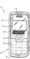
Fig. 1,2 and 3A-3B electronic equipment 10 is expressed as " brick " or " straight plate " kind of design housing, but should be understood that, also can utilize other type housing, and can not depart from the scope of the present invention such as flip-type housing (shown in Fig. 4-8) or slide cover type housing.
As Fig. 1,2 and 3A-3B shown in, electronic equipment 10 can comprise the housing 23 that holds user interface 12 (shown in the dotted line).User interface 12 make usually the user can be easily and carry out effectively one or more communication task (for example, the sign contact person, select the contact person, carry out call, receive call, moving cursor, navigation show etc. on display).The user interface 12 (shown in the dotted line) of electronic equipment 10 generally includes one or more in the following assembly: display 14, alphanumeric keypad 16 (shown in the dotted line), function key 18, moving detecting circuit 20, one or more light source 21, loudspeaker 22 and microphone 24.
Moving detecting circuit 20 can be can inspected object move and needn't contacting electronic equipments 10 and/or the circuit of any kind of moving detecting circuit 20.Moving detecting circuit 20 can be non-contacting sensor, single-sensor, a plurality of sensor and/or sensor array.Unless otherwise stated, term " moving detecting circuit " is intended to be broadly construed to encompass any structure of sensor, any amount of sensor and/or the sensor of any kind that move of inspected object above described one or more sensor non-contactly.Exemplary sensor comprises that imageing sensor (for example, charge-coupled device (CCD) or complementary metal oxide semiconductor (CMOS) (CMOS), infrared sensor are (for example, phototransistor and photodiode), sonac, electromagnetic sensor, thermal sensor (for example, heat sensitive sensor), location and/or position transducer etc.In addition, moving detecting circuit 20 can also touch dependent sensor (for example, capacitive type touch pad, mouse, touch pad, touch-screen, capacitance type sensor etc.) in conjunction with routine and use, and is as described below.
Moving detecting circuit 20 can be positioned at any desired location of electronic equipment 10.The position of moving detecting circuit 20 can be considered and difference based on many designs.This design is considered for example to comprise: the quantity of used type of sensor, sensor, the size and dimension of electronic equipment etc.For example, moving detecting circuit 20 can be positioned at shown in Fig. 1 and 3A near the electronic equipment central authorities, is positioned at as shown in Figure 2 near the circumference of housing 23 of electronic equipment, perhaps is positioned at shown in Fig. 3 B near the end of housing 23 of electronic equipment.In addition, the position of moving detecting circuit 20 can be different because of the type of electronic device of being incorporated into.For example, if electronic equipment is an alarm clock, then moving detecting circuit 20 can be positioned at the top of alarm clock.Equally, user input apparatus can be positioned on a plurality of surfaces of electronic equipment, thereby makes things convenient for the user.If electronic equipment can use by multiple mode and/or orientation, then this is convenient especially for the user.For example, if electronic equipment is a portable communication appts, then moving detecting circuit 20 can be positioned on the front and back of this device.
With reference to Fig. 4 to 8, illustration have an electronic equipment 10 of renovating housing 23.Moving detecting circuit 23 is arranged on the outside surface of housing 23 usually.Usually consider based on above-mentioned identical design that moving detecting circuit 20 can be positioned near (Fig. 4, the 5 and 6) end of housing, be positioned at (Fig. 7) on the periphery of housing 23, be positioned at the central authorities (Fig. 8) of housing 23, or any position grouping on the housing 23.
Equally, moving detecting circuit 20 can have the sensor of any desired number and/or structure.For example, can locate a plurality of sensors, shown in Fig. 3 B, 6 and 8, locate single-sensor by the matrix form shown in the triangle shown in Fig. 1,2,4 and 7, the employing Fig. 3 A and 5.Other exemplary configuration comprises line oriented, rectangular orientation, square orientation, orientation of polygon, circular orientation etc.As mentioned above, those of ordinary skills should be understood that the quantity of sensor can be considered for design with structure, function is considered, and/or aesthetics is considered.
Among Fig. 1,2,4 and 7 illustration adopt the demonstration moving detecting circuit 20 of a plurality of forms of sensor of triangular construction.As shown in the figure, moving detecting circuit 20 comprises a plurality of sensors (for example, sensor " a ", " b " and " c ").In this embodiment, utilize three sensors to obtain three-dimensional moving and/or position data.As described below, may wish to use more multisensor, so that higher precision is provided and the more system of robust is provided.In addition, may wish to use imageing sensor (for example, video camera), it generally includes the sensor of a plurality of intensive assemblings, with near the movement of objects the detected electrons equipment 10.
With reference to Figure 10, illustration at the side cross-sectional view of the exemplary output field of sensor " a " and " b " (for clarity sake having omitted view) at sensor " c ".As shown in figure 10, provide illumination field (shown in the dotted line) by light source 21.This illumination field is generally three-dimensional taper.There is the corresponding checkout area that is associated with " a " and " b " sensor.These checkout areas also are three-dimensional taper usually.Sensor " a " and " b " are configured to usually, detect when object enters corresponding checkout area and move, and be as described below.
With reference to Figure 11, illustration at the sectional top view of the exemplary output field of sensor " a ", " b " and " c ".Each sensor all has the zone that overlaps with one or two other sensor and the amplitude of measuring usually mainly from the zone of a sensor.With reference to Figure 11, along with between " a ", " b " and " c " sensor, detecting along continuous straight runs moving horizontally from left to right, as shown in figure 11, drawn among Figure 12 at each sensor and output amplitude signal correction connection and the exemplary curves of time relation.Equally, the vertical moving from the surface of electronic equipment 10 to the effective target scope of sensor provides as shown in figure 13 at the amplitude of each sensor and the exemplary curves of time relation.
It is readily appreciated by a person skilled in the art that the feature curve of output will be according to the structure of sensor and detected moving (for example, level, vertical, diagonal angle, circle etc.) and different.For example, with reference to Figure 11, for sensor " a " and " b ", and for comparing at the detected output amplitude of sensor " c ", move horizontally proximity transducer " a " and " b " more, detected amplitude is high more, as shown in figure 12.Medially be applied to all sensors (for example, " a ", " b " and " c ") if will move horizontally, the curve of then representing sensor " c " will have with Figure 12 in sensor " a " and " b " roughly the same amplitude.
Utilize these principles, aspect of the present invention relates to the moving detecting circuit 20 with one or more sensor, and it is used near the movement of objects definite electronic equipment 10.For example, detect the hand and/or object the moving of associated user along x, y and z direction.When in moving detecting circuit 20, having used a plurality of sensor, from the output of the amplitude of respective sensor (for example, from sensor " a ", " b " and " c ") will be usually with to the distance of reflecting object and proportional from the reflectivity of this object itself.Thereby, the relative distance and the type (for example, vertically, level, diagonal angle, circle etc.) that can detect and quantize to move.For example, can detect up and down move, along laterally the moving of any direction, clockwise and be rotated counterclockwise.In case detect mobilely, just can use with detected and move corresponding control signal and control difference in functionality in the electronic equipment (for example, the beginning of sound level, application and stop, the scrolling of menu, carry out menu selection etc.).
The sensor that comprises moving detecting circuit 20 is connected to analog to digital converter 75 usually, as shown in Figure 9.Analog to digital converter 75 converts the analog output signal of respective sensor to corresponding digital signals, to be input in the control circuit 50.Make signal after the conversion can be used for other assembly (for example, algorithm 56, control circuit 50, storer 54 etc.) of electronic equipment 10, determine whether object moves and the moving of inspected object in the scope of sensor with further processing.
In general, predetermined move of object in the sensor effective range will generate corresponding predetermined control signal.This predetermined control signal can be based on one or more state of electronic equipment 10 and is different.For example, detected moving can cause generating such control signal when carrying out a certain application (for example, audio frequency and/or video player),, skips to the next song of the content of multimedia that presents on the electronic equipment that is.Yet detected same user moves and can generate the control signal of carrying out difference in functionality (for example, close the quarter-bell that triggered, close the tinkle of bells, send the calling that is used for voice mail etc.) when carrying out Another Application, and is as described below.Equally, detected object speed and/or acceleration can also generate the control signal of carrying out difference in functionality.For example, slowly move horizontally from left to right and can trigger the F.F. action, skip to next song function and move horizontally from left to right fast to trigger.
It is that the dotted line that initial point is dispersed identifies that the target field that is associated with each sensor of moving detecting circuit 20 is all used in Figure 10 and 11 with each sensor.At the target field of each sensor normally from the outward extending cone shape of sensor surface.Preferably, the effective range of sensor is approximately from the surface of this sensor 40 centimetres.The effective range distance of sensor (or to) will be according to the definite application of sensor and different.For example, less electronic installation needs less coverage to operate this device usually.And bigger device may need bigger coverage to operate one or more feature of this device.Those of ordinary skills understand easily, the effective range of sensor can be based on a plurality of parameter (electric power that provides as the normal range of operation of sensor type, sensor, sensor application, to light source, detected parameter etc. for instance) and is different.
Shown in Fig. 3 B and 4-8, housing 23 can comprise the light source 21 that is used to throw light on roughly with the effective range overlapping areas of sensor.This light source can be the light source of any hope.Exemplary light source 21 can be conventional light emitting diode, infrarede emitting diode or camera flash lamp.Preferably, light source 21 has the efficient working range of the working range that roughly comprises sensor.
In one aspect of the invention, can use light to come illuminated objects (for example, user's hand, indicator etc.) from light source 21.Preferably, utilize high frequency (for example, 33kHz) light source 21 to be modulated, enabled to suppress DC and low-frequency disturbance (for example, sunlight and from the 100/120Hz light of lamp).The chopped radiation (for example, infrared light) of reflection is detected by user input apparatus sensor (for example, sensor " a ", " b " and " c ").As mentioned above, infrared ray sensor can be phototransistor or photodiode.Sensor should have is enough to utilize light source 21 to obtain the suitably opening angle of (right) spatial resolution, as shown in figure 10.
Before detected signal is fed to analog to digital converter 75, can amplify it, high-pass filtering and amplitude detect, as shown in Figure 9.After detected signal is carried out digitizing, can calculate at each sensor and angle this signal correction connection and definite position and/or move.By sending light modulated by 20-100Hz speed with short, can save energy according to required resolution.Infrarede emitting diode preferably has the opening angle that the opening angle (for example, the angle between the relative both sides of cone) with sensor is complementary, and this has generally guaranteed radiative best the use, as mentioned above.
As mentioned above, will be coupled to modulus (A/D) converter 75 from the data of described one or more sensor that comprises moving detecting circuit 20, as shown in Figure 9.(for example, when not having object to cover in these sensors one or more) can measure the off-set value with respect to sensor, and export A/D converter 75 under idle pulley.In order to ensure detecting object, with detect noise or other false (spurious) signal opposite, threshold voltage can be applied to from one or more data-signal of A/D converter 75 outputs.If value surpasses certain threshold level, then measured value can be regarded as effectively (that is, having detected object above one or more sensor).
User above the sensor that comprises moving detecting circuit 20 moves common meeting and provides to this sensor that () different amplitudes and angle for example, user's hand, it can calculate illustrative with graphics mode as Figure 12 from object.
Angle between two sensors may be calculated:
Wherein, " a " and " b " is respectively the output amplitude from sensor.As it is readily appreciated by a person skilled in the art that and to use standard trigonometry computing method to come the vertical of calculating sensor top and/or move horizontally.
Fig. 3 A and 5 illustrations another the demonstration moving detecting circuit 20.Illustrative moving detecting circuit 20 has adopted the form of sensor array.This moving detecting circuit 20 can be based on determining moving along X, Y and Z axle with above-mentioned roughly the same principle.For example, detecting when mobile, each sensor in this array is all exported and can be used to allow respective value that object is followed the tracks of.Based on detected mobile starting position and speed, acceleration and/or path, can generate the corresponding control signal of one or more parameter that is used to control electronic equipment and/or application.
As mentioned above, moving detecting circuit 20 can also adopt the form of the video camera that comprises one or more imageing sensor that is used to take digital picture and/or film.Can will be stored in the storer 54 with picture and/or the corresponding image of film and/or video file temporarily and/or for good and all.In some embodiments, electronic equipment 10 can comprise light source 21, and this light source is the standard camera flashlamp, and it helps video camera to take pictures and/or film under the specific illumination condition.
In addition with reference to Figure 14, illustration constitute the process flow diagram of box of special characteristic of the moving detecting circuit 20 of video camera form.This process flow diagram can be regarded as describing the step of a method.Although Figure 14 shows the concrete order of carrying out functional logic blocks, the execution sequence of these frames can with respect to shown in order change.And two or more frames that illustrate in succession can side by side be carried out simultaneously or partly.Can also omit particular frame.In addition, for strengthening purposes such as practicality, book keeping operation, performance, measurement, trouble hunting, order, state variable, signal (semaphore) or the message of any amount can be added in this logic flow.Should be understood that all this modified examples all within the scope of the invention.
In frame 90, can begin this method by activating moving detecting circuit 20.As previously mentioned, moving detecting circuit 20 can adopt the form of video camera and/or other non-contacting sensor.Activation to moving detecting circuit 20 can be called by the mode of any hope.For example, can be when sensing the predetermined condition of electronic equipment, internal event takes place (for example, trigger quarter-bell) time, external event takes place (for example, receive and call out and/or message) time, and/or when any other desired way or trigger event, automatically call moving detecting circuit 20 by user action (for instance, as the flip-shell housing of the particular key by pushing keypad 16, closed electronic equipment 10, receive incoming call and/or message, triggering quarter-bell etc.).It is readily appreciated by a person skilled in the art that the project of listing above is actually exemplary, and the parameter and/or the condition of activation moving detecting circuit 20 there are many kinds.
Because the power consumption demand of moving detecting circuit 20 is useful thereby the electric power of saving electronic equipment optionally activates moving detecting circuit 20.It is all the more so when electronic equipment comprises the portable communication appts that has limited and/or power-limited (for example, battery) usually.In other cases, when electronic equipment always is connected to power supply usually,, can activate moving detecting circuit 20 all the time if wish.
When moving detecting circuit 20 was activated, at step 92 place, moving detecting circuit 20 was placed under the Data Detection pattern (for example, the image detection pattern), to obtain image and/or sensing data.Under the Data Detection pattern, can activate moving detecting circuit 20 and come inspected object comprising moving above described one or more sensor of moving detecting circuit 20.Discussed in more detail below, image detection circuit 20 allows the user to control electronic equipment 10 by carry out user action (for example, gesture) in the field of image detection circuit 20, and physics contacts this electronic equipment 10 and do not need in fact.In case detect this user action, electronic equipment just can be carried out a certain function based on detected user action.
At step 94 place, moving detecting circuit periodically obtains data point (for example, image and/or data) by scheduled time slot.The period of obtaining between the image can be the period of wishing arbitrarily.This period can be selected from the period of scheduled time slot and/or user's setting.Preferably, between the Ser.No. strong point, pass through less than 2 seconds.More preferably, obtaining between the Ser.No. strong point through about 1/4 second.If through the long time, then may be difficult to detect predesignated subscriber's action above motion detection circuit because of the speed that object can move.These data can be stored in the storer temporarily, till scheduled event takes place.
At step 96 place, usually these data are handled to determine the generation of scheduled event.These data can be handled by any means to determine whether to have taken place scheduled event.For example, can be compared to each other two or more images and/or data point determine whether to have taken place scheduled event.In another example, can search each image and/or data point and see whether there is scheduled event.This scheduled event can be any detectable user action.Appropriate users action for example comprises: movement of objects, level and/or vertical moving, user's gesture, wave etc.
At step 98 place, regardless of the type of employed moving detecting circuit 20, in case detected predesignated subscriber's action by any method, just can be based on the control signal that is used for control operation and/or function that generates of predesignated subscriber's action.Performed function can be can be by electronic equipment and/or any function that is realized by the performed software application of this electronic equipment.Following operating position is actually exemplary, but not is intended to scope of the present invention is limited.
Embodiment 1: with call denial/quiet
With reference to Figure 15, at step 100 place, electronic equipment receipt of call and/or message.At step 102 place, export a signal to associated user and received incoming call and/or message with expression.At step 104 place, activate moving detecting circuit 20.Optionally, gesture can also occur and/or move the control icon on display, they can be seen by the user, be movable thereby indicate moving detecting circuit 20 to the user.In addition, can make one or more light emitting diode (LED) and/or display lamp gradually bright (fade in), with at least a portion of illumination moving detecting circuit 20.At step 106 place, detect user action based on the information of periodically obtaining from moving detecting circuit 20.In this embodiment, the mobile detection data of obtaining can be corresponding to exemplary mute function and/or exemplary refusal function.For example, detect an object (for example, the hand of associated user) and move down above moving detecting circuit 20, as shown in figure 16, it finally touches electronic equipment and/or covers moving detecting circuit 20 and reach predetermined several seconds (for example, approximately 2-3 second).In another embodiment, user action can be that the horizontal hand in predetermined several seconds (for example, approximately 2-3 second) moves and (for example, moves from left to right and/or from right to left across moving detecting circuit 20, as shown in figure 17).At step 108 place, move based on detected user, generate a control signal (control) thus to call out quiet and/or the refusal.At step 110 place, make moving detecting circuit 20 invalid (deactivated).In addition, no longer show optional gesture control icon on the display, and can close LED.
Embodiment 2: the greedy quarter-bell of sleeping
Figure 18 illustration another demonstration methods according to aspects of the present invention.With reference to Figure 18,, the quarter-bell that is contained in the electronic equipment 10 is arranged in the particular moment sounding at step 120 place.At step 122 place, activate moving detecting circuit 20 in the moment of quarter-bell sounding.Optionally, gesture can also occur and/or move the control icon on display, they can be seen by the user, be movable to indicate moving detecting circuit 20 to the user.In addition, can make one or more light emitting diode (LED) and/or display lamp gradually bright, with at least a portion of illumination moving detecting circuit 20.At step 124 place, detect user action corresponding to " greedy sleeping " function.This snooze stops quarter-bell and it is arranged in after the short period (any time between five minutes to ten minutes usually) and rings once more.For example, detect an object (for example, the hand of associated user) and move down above moving detecting circuit 20, it finally touches electronic equipment and/or covers moving detecting circuit 20 and reach predetermined several seconds (for example, approximately 2-3 second), as shown in figure 16.In another embodiment, user action can be that the horizontal hand in predetermined several seconds (for example, approximately 2-3 second) moves (for example, moving from left to right and/or from right to left across moving detecting circuit 20), as shown in figure 17.At step 126 place, carry out a certain function based on the appearance of scheduled event.For example quarter-bell diminuendo and can close LED.At step 128 place, determine that quarter-bell is closed or " greedy sleeping ", if quarter-bell is " greedy sleeping " then repetitive sequence 122 to 128, till associated user final plant closure quarter-bell.At step 130 place,, just make moving detecting circuit 20 invalid in case closed quarter-bell.In addition, no longer show optional gesture control icon on the display, and can close LED.
Embodiment 3: regulate volume
Can also control from electronic equipment and/or be connected to the external loudspeaker of this electronic equipment and/or the volume of the sound signal of device output by detecting the object that in the field of moving detecting circuit 20, moves.In this embodiment, suppose that electronic equipment is just by loudspeaker output audio stream.This loudspeaker can be positioned at this electronic equipment internal or be positioned at this electronic device exterior.With reference to Figure 19,, provide the audio frequency of exporting by loudspeaker to electronic equipment 10 at step 140 place.When activating audio frequency output,, activate moving detecting circuit 20 at step 142 place.Optionally, gesture can also occur and/or move the control icon on display, they can be seen by the user, be movable to indicate moving detecting circuit 20 to the user.In addition, can make one or more light emitting diode (LED) and/or display lamp gradually bright, with at least a portion of illumination moving detecting circuit 20.At step 144 place, detect user action corresponding to scheduled event according to the data of periodically obtaining from moving detecting circuit.At step 146 place, move the function that generates and will carry out and/or operate corresponding control signal based on detected.For example, as shown in figure 16, above moving detecting circuit 20, move down, then volume can be reduced if detect an object.If this object finally touches electronic equipment and/or covers moving detecting circuit 20 and reach predetermined several seconds (for example, approximately 2-3 second), then can stop the application of output audio stream, discussed in more detail below.In another embodiment, move up, then volume can be increased if detect an object.In another embodiment, user action can be that the horizontal hand across moving detecting circuit 20 in predetermined several seconds (for example, approximately 2-3 second) moves (for example, moving from left to right and/or from right to left), with will be quiet, as shown in figure 17 from the sound of loudspeaker.In another embodiment, this object can move along clockwise direction to increase volume and/or to move to reduce volume in the counterclockwise direction.At step 148 place, in case close the application of controlling volume and/or play multimedia content and/or close electronic equipment, just can make moving detecting circuit 20 invalid, state as step 150 place; Otherwise can repeating step 144-148.In addition, the optional gesture that can also close on the display is controlled icon.
Embodiment 4: touch and close
Another aspect of the present invention is devoted to detect and touch closing function with moving and is combined, as shown in figure 20.With reference to Figure 20, at step 160 place, when electronic equipment 10 when receiving incoming call, can activate moving detecting circuit.At step 162 place, moving detecting circuit obtains mobile message.At step 164 place, this mobile message is handled to determine whether this mobile message moves corresponding to the predesignated subscriber.At step 166 place, if scheduled event has taken place, then based on the generation of this scheduled event and carry out a certain function and/or operation.For example, the user can be positioned at their hand moving detecting circuit 20 tops and his or her hand is shifted to sensor, and this can reduce the volume of the tinkle of bells.At step 168 place, when reaching predetermined threshold, the hand (with before or after electronic equipment contacts) that is moved further this user towards electronic equipment 10 will cause contacting this electronic equipment and carrying out another function based on threshold value that reaches and/or object.For example, when reaching threshold value and/or contact this electronic equipment, can will call out quiet and/or be forwarded to some other user definition features of voice mail or activation.Equally, if electronic equipment is serving as quarter-bell and is triggering quarter-bell, then can be corresponding to reducing volume and at user's hand in fact before the contacting electronic equipments 10 and/or the order of final plant closure quarter-bell afterwards above the sensor by mode mobile object from the top down.In either case, the volume of ringer and/or quarter-bell can be reduced to the point that this device is programmed to close, and/or in fact user's hand can touch the touch sensor that is associated with electronic equipment to close this ringer and/or quarter-bell.
Embodiment 5: skip a head and sing or retreat and/or F.F.
Figure 22 illustration another demonstration methods according to aspects of the present invention.With reference to Figure 22,, on electronic equipment 10, carry out audio player application at step 220 place.In this audio player application, provide multiple choices to the user, for example comprise next song and/or the previous song that skips to playlist and/or retreat and/or the part of F.F. by the audio played at present file.At step 222 place, in the period of audio player application activity, activate moving detecting circuit 20.Optionally, gesture can also occur and/or move the control icon on display, they can be seen by the user, be movable to indicate moving detecting circuit 20 to the user.In addition, can make one or more light emitting diode (LED) and/or display lamp gradually bright, with at least a portion of illumination moving detecting circuit 20.At step 224 place, detect corresponding to the user action of being scheduled to mobile or incident.Should predetermined move or incident can be moving of wishing arbitrarily.For example, this is scheduled to move or incident can be corresponding to the song turn function.This song turn function can stop in progress current audio file according to detected motion and skip to next song or previous song.For example, demonstration song turn function can be corresponding to, detected object (for example, the hand of associated user) in that move from left to right by very fast speed (for example, in 1 second) above the moving detecting circuit 20 can be corresponding to skipping to next song.In another embodiment, detected object (for example, the hand of associated user) is in that move from right to left by very fast speed (for example, in 1 second) above the moving detecting circuit 20 can be corresponding to skipping to previous song.Equally, if detect same movement of objects, but speed is slower, then can carry out difference in functionality.For example, the demonstration fast-forward functionality can corresponding to, detected object (for example, the hand of associated user) can be corresponding to the part of F.F. by the audio played at present file by moving from left to right than slow rate (for example, greater than 1 second) above moving detecting circuit 20.In another embodiment, detected object (for example, the hand of associated user) can be corresponding to a part that retreats by the audio played at present file by moving from right to left than slow rate (for example, greater than 1 second) above moving detecting circuit 20.At step 226 place, carry out corresponding function based on the appearance of scheduled event, as mentioned above.At step 228 place, determine whether to have stopped electronic equipment and/or player application.If do not stop electronic equipment and/or player application, then repetitive sequence 224 to 226, till having stopped audio player application.At step 230 place,, just make moving detecting circuit 20 invalid in case stopped audio player application.In addition, no longer show optional gesture control icon on the display, and can close LED.
Embodiment 6: F.F./or retreat
Figure 23 illustration another demonstration methods according to aspects of the present invention.With reference to Figure 23,, on electronic equipment 10, carry out audio player application at step 240 place.In this audio player application, provide multiple choices to the user, for example comprise next song and/or the previous song that skips to playlist and/or retreat and/or the part of F.F. by the audio played at present file.At step 242 place, in the period of audio player application activity, activate moving detecting circuit 20.Optionally, gesture can also occur and/or move the control icon on display, they can be seen by the user, be movable to indicate moving detecting circuit 20 to the user.In addition, can make one or more light emitting diode (LED) and/or display lamp gradually bright, with at least a portion of illumination moving detecting circuit 20.At step 244 place, detect corresponding to the user action of being scheduled to mobile or incident.This is scheduled to move or incident can be moving of any hope.For example, this is scheduled to move or incident can be corresponding to F.F. and/or fallback function.This F.F. and/or fallback function can stop in progress current audio file and laterally skip the part of current displaying audio file.According to detected motion, the redirect part can be the part of first forward direction user output and/or a part of not exporting to the user as yet.For example, the song fallback function can corresponding to above the first of moving detecting circuit 20 (for example, the left side of moving detecting circuit 20) keep object (for example, the hand of associated user) fixedly to reach a certain period (for example, 2-3 second).In another embodiment, the song fast-forward functionality can corresponding to above the second portion of moving detecting circuit 20 (for example, the right side of moving detecting circuit 20) keep object (for example, the hand of associated user) fixedly to reach a certain period (for example, 2-3 second).At step 246 place, carry out corresponding function based on the appearance of scheduled event, as mentioned above.At step 248 place, determine whether to have stopped electronic equipment and/or player application.If do not stop electronic equipment and/or player application, then repetitive sequence 244 to 246, till having stopped audio player application.At step 250 place,, just make moving detecting circuit 20 invalid in case stopped audio player application.In addition, no longer show optional gesture control icon on the display, and can close LED.
It is readily appreciated by a person skilled in the art that the foregoing description is the illustration to aspect of the present invention.Others of the present invention for example comprise: the predetermined hand of moving detecting circuit 20 tops of electronic equipment is moved and calls out, sends message and/or otherwise begin a series of processing and/or step to get in touch the individual and/or group associates.For example, contact person A can associate with the object that carries out circular motion above moving detecting circuit 20 (for example, user's hand).When detecting object this mobile, can generate the control signal that makes electronic equipment carry out predetermined function and/or processing (for example, calling out the individual who is associated with circular motion).
Those of ordinary skills also understand easily, and other moves the action that also can be used to start electronic equipment.For example, can be with the mobile execution specific function that is programmed for of square, rectangle, ellipse, rhombus, straight line or any polygonal shape.
Except the position data that moving detecting circuit 20 detects, also can detect other parameter and/or information (for example, speed, acceleration, moment etc.) and be made and be used for handling by electronic equipment.For example, moving detecting circuit 20 is detected vertical and/or move horizontally and can be configured to, (for example has first speed in vertical moving, speed less than threshold value) cause predetermined response to the time, if and this vertical moving has faster speed (for example, the detected speed that surpasses threshold value) and then causes second response.
Equally, when moving detecting circuit 20 detects object when leaving electronic equipment than the slow speed of the first predetermined threshold speed, can generate the control signal that the volume that causes being associated with the output of electronic equipment increases by first set rate.When user's input circuit detects object when leaving electronic equipment than the fast speed of the first predetermined threshold speed, can generate the control signal that causes the volume that is associated with the output of electronic equipment to increase by second set rate, wherein, second set rate is faster than first set rate.
In another embodiment, when moving detecting circuit detects the object almost fixed and reaches schedule time amount and electronic equipment and be in battery saving mode, can generate the control signal that this electronic equipment is activated from battery saving mode.
In another embodiment, when moving detecting circuit detects at least one in horizontal plane and/or vertical plane of object when moving by diagonal path across moving detecting circuit, can generate the predetermined control signal of the application and/or the processing that are used to control electronic equipment.Equally, when moving detecting circuit detects object when circular pattern moves, can generate the predetermined control signal of the application and/or the processing that are used to control electronic equipment.
Except beyond the moving of inspected object (for example, user's hand), moving detecting circuit 20 can also detect each finger and/or a plurality of object (for example, many hands) moving in the scope of moving detecting circuit of the hand of associated user.Detect thisly when mobile, can generate the control signal of the application and/or the processing that are used to control electronic equipment.
According to aspects of the present invention, the user can be input to new user action in predesignated subscriber's maneuver library.The method of training this system to discern new user action has a variety of.All this methods all fall within the scope of the present invention.A kind of processing that is used to train is by training to be moved the predetermined of system identification object.For example, in one embodiment, extract the sample of new user action.Image is associated with specific user action and stores.Other method comprises in the field that is provided at moving detecting circuit 20 to be carried out user action specific time and the sample new user action that obtains.This needs some user interventions naturally.In a preferred embodiment, this user or a plurality of user carry out new user action about 10 times.Number of users and sample number have direct influence to the precision of the model of expression user action and the statistics precision of each key point.In general, the representative sample that provides to native system is many more, and identification is handled will get over robust.In one embodiment, the many key points in sign and the input user action.For example, comprise that the user action of " circumference " motion, the object that carries out circular motion can repeat above moving detecting circuit 20.Then, after having determined movement of objects, can identify time of these points and position and be associated with the specific function that will carry out.
Moving detecting circuit can also comprise microphone 24, with the earcon of object mobile in the limited range that detects comfortable mobile detection zone.This earcon can be derived from any source.The demonstration source of earcon according to aspects of the present invention comprises: user's brouhaha, snap sound, voice etc.
Moving detecting circuit 20 can provide one or more signal to processor 52 (shown in Figure 9), wherein, these signal indications object moving and/or the position in the target area.Moving detecting circuit 20 can provide at the separation signal of position signalling and/or makes up these signals or more composite signals for each sensor.Preferably, assembling position and time data are so that determine object (for example, user's hand) moving in the target area, speed and/or acceleration.
The object of measuring can be any suitable object.Suitable object for example comprises: the hand of associated user, one or more finger, many hands, contact pilotage, indicator, pen, game console and/or instruments, surface, wall, platform etc.Can be directly and/or measure movable signal (also being called position signalling) indirectly at this.In one aspect of the invention, handle these signals indirectly, so that determine mobile message, speed and/or acceleration.
With reference to Fig. 9, processor 52 is handled the signal that receives from moving detecting circuit 20 by any desired way.Processor 52 can be worked in conjunction with application software 56 and/or other application and/or storer 54, so that function described here to be provided.
Storer 54 for example can be buffer, flash memory, hard disk drive, removable media, volatile memory and/or nonvolatile memory.In addition, treating apparatus 52 is carried out the code of the various functions that are used to carry out electronic equipment 10.Storer can comprise one or more application program and/or module 56, to carry out the software and/or the hardware operation of any hope that is associated with electronic equipment 10.
In order to set up and other radio communication that is positioned at local device (as wireless head-band earphone, another mobile phone, computing machine etc.), electronic equipment 10 can comprise local wireless interface adapter 72.This wireless interface adapter 72 can be to operate any adapter of communicating by letter between electronic equipment 10 and the electronic installation to facilitate.For example, wireless interface adapter 50 can support to utilize the communication of Bluetooth, 802.11, WLAN, Wifi, WiMax etc.
Moving of object can detect by multiple mode.For example, have one or more kind methods and detect moving across the object of one or more sensor level and/or vertical moving.With reference to Figure 21, illustration according to the demonstration methods of one aspect of the invention.This method provides near a kind of method that moves of detected electrons equipment that is used for.At step 200 place, this method comprises: provide to comprise that the moving detecting circuit 20 that is arranged in the housing (for example, optical sensor (for example, video camera), sensor " a ", " b " and " c " etc.) electronic equipment 10, wherein, near the movement of objects this moving detecting circuit detected electrons equipment and export corresponding mobile message.At step 202 place, processor is handled the mobile message that receives from moving detecting circuit and is generated control signal based on one or more signal that receives from moving detecting circuit at least in part.At step 204 place, generate pre-set output signal based on detected moving.At step 206 place, change or otherwise revise the operating parameter that is associated with this electronic equipment and/or the application on this electronic equipment, carried out.This control signal can be controlled one or more aspect of the performed application of this electronic equipment and/or this electronic equipment, as mentioned above.
Computer program component of the present invention can be implemented as hardware and/or software (comprising firmware, resident software, microcode etc.).The present invention can take the form of computer program, its can by have be embodied in for the computing machine in the medium that instruction execution system uses or the combined command executive system is used can with or the computing machine of computer-readable program instructions, " code " or " computer program " can with or computer-readable recording medium specifically implement.In the context of this document, computing machine can with or computer-readable medium can be can comprise, store, transmit, propagate or transport for instruction execution system, device or equipment uses or any medium of the program that combined command executive system, transposition or equipment use.Computing machine can with or computer-readable medium for example can be but be not limited to electricity, magnetic, light, electromagnetism, infrared ray, or semiconductor system, device, equipment or such as the propagation medium of the Internet.It should be noted that, computing machine can with or computer-readable medium in addition can be can print routine on it paper or another suitable medium, because this program can be for example via this paper or another medium being carried out optical scanning and obtaining in the electronics mode, then compile, explain, or otherwise handle by suitable method.Computer program described here and any software and hardware have formed the various devices that are used for carrying out in example embodiment function of the present invention.
The specific embodiment of the present invention is disclosed at this.Those of ordinary skills recognize that easily the present invention can have other application under other environment.In fact, many embodiments and realization all are fine.Following claims never are to limit the scope of the present invention to above-mentioned embodiment.In addition, any " be used for ... device " statement all be intended to arouse the understanding that the device of parts and claims is added function, yet, not concrete use statement " be used for ... device " any parts all should not be construed as device and add functional part, also be like this even claims comprise literal " device " in addition.Listed the method step that takes place by particular order although should also be noted that this instructions, these steps can be by any orders or are carried out simultaneously.
Claims (43)
1, a kind of electronic equipment (10), this electronic equipment comprises:
Moving detecting circuit (20), this moving detecting circuit is set for and detects near the movement of objects of described moving detecting circuit, wherein, described moving detecting circuit comprises at least one sensor, and corresponding at least one output signal in the position of generation and detected object;
Processor (52), this processor is connected to described moving detecting circuit, wherein, described processor receives one or more signal from described moving detecting circuit, and exports a control signal based on detected described one or more signal of described moving detecting circuit at least in part.
2, electronic equipment according to claim 1, wherein, described moving detecting circuit is a video camera.
3, according to any described electronic equipment among the claim 1-2, wherein, described sensor is an imageing sensor.
4, according to any described electronic equipment among the claim 1-3, wherein, described sensor is at least one sensor of selecting from the group of being formed with lower sensor: charge-coupled device (CCD) sensor or complementary metal oxide semiconductor (CMOS) (CMOS) sensor.
5, according to any described electronic equipment among the claim 1-4, described electronic equipment also comprises the storer (54) that is connected to described processor, and this storer is used for storage and corresponding described at least one output signal of detected movement of objects.
6, according to any described electronic equipment among the claim 1-5, described electronic equipment also comprises the mobile detection algorithm (56) in the described storer, and this moves detection algorithm and is used for determining and the corresponding mobile message of the detected object space of described moving detecting circuit.
7, according to any described electronic equipment among the claim 1-6, wherein, described mobile detection algorithm to first period from described at least one output signal of described moving detecting circuit with described at least one output signal from described moving detecting circuit compares in second period.
8, electronic equipment according to claim 7 wherein, is the form of view data from the output signal of described first period with from the output signal of described second period.
9, according to any described electronic equipment among the claim 1-8, described electronic equipment also comprises the housing at least a portion of described moving detecting circuit and described processor be contained in.
10, according to any described electronic equipment among the claim 1-9, wherein, described at least one sensor is positioned on the outside surface of described housing.
11, according to any described electronic equipment among the claim 1-10, wherein, described moving detecting circuit comprises a plurality of sensors.
12, electronic equipment according to claim 11, wherein, at least one in the described sensor is infrared sensor.
13, according to any described electronic equipment among the claim 1-12, wherein, described moving detecting circuit detects moving near the target field of described electronic equipment.
14, according to any described electronic equipment among the claim 1-13, described electronic equipment also comprises the storer that is connected to described processor, and this storer is used for storage and corresponding described at least one output signal of detected movement of objects.
15, electronic equipment according to claim 14, described electronic equipment also comprise the mobile detection algorithm in the described storer, and this moves detection algorithm and is used for determining and the corresponding mobile message of the detected object space of described moving detecting circuit.
16, electronic equipment according to claim 15, wherein, described mobile detection algorithm to first period from described at least one output signal of described moving detecting circuit with described at least one output signal from described moving detecting circuit compares in second period.
17, according to any described electronic equipment among the claim 1-16, described electronic equipment also comprises at least a portion of holding described moving detecting circuit and the housing of described processor.
18, electronic equipment according to claim 17, wherein, described at least one sensor is positioned on the outside surface of described housing.
19, near the method that moves a kind of detected electrons equipment (10) said method comprising the steps of:
One electronic equipment is provided, and this electronic equipment comprises the moving detecting circuit that is arranged in the housing (23), and wherein, described moving detecting circuit detects near movement of objects and the output mobile message the described electronic equipment;
The described mobile message that receives from described moving detecting circuit is handled, so that small part ground generates the control signal of one or more operation that is used to control described electronic equipment based on described one or more signal that receives from described moving detecting circuit.
20, method according to claim 19, wherein, described moving detecting circuit is a video camera.
21, according to any described method among the claim 19-20, wherein, described sensor is an imageing sensor.
22, according to any described method among the claim 19-21, wherein, predetermined move of described moving detecting circuit inspected object in target field.
23, method according to claim 22 wherein, generates pre-set output signal based on detected predetermined moving.
24, according to any described method among the claim 22-23, wherein, described detected predetermined moving comprises that object moves vertically downward towards described moving detecting circuit.
25, method according to claim 24, wherein, the described output signal that is used for carrying out at least one function of the group of forming by following function corresponding to generation that moves vertically downward: the volume of the ringing volume that reduces to be associated, the loudspeaker that reduction is associated with described electronic equipment with incoming call, perhaps generation be used to make with incoming call, message with and/or warn the quiet quiet operation of ringing volume that is associated.
26, method according to claim 23, wherein, described detected predetermined moving comprises that object moves vertically upward from described moving detecting circuit.
27, method according to claim 26, wherein, the described output signal that is used for carrying out at least one function that the group is made up of following function selects corresponding to generation that moves vertically upward: the volume that increases the loudspeaker that is associated with described electronic equipment with the send a telegram here ringing volume that is associated or increase.
28, method according to claim 23, wherein, the detected vertical moving of described moving detecting circuit causes first response when described vertical moving has first speed, cause second response if described vertical moving has than the described first speed faster speed.
29, method according to claim 23, wherein, described moving detecting circuit is detected to move horizontally described moving horizontally and causes first response when having first speed, if described moving horizontally has than the described first speed faster speed then cause second response.
30, method according to claim 19, wherein, the detected object of described moving detecting circuit is set as at quarter-bell across moving horizontally of described electronic equipment and closes the time control one greedy alarm of sleeping.
31, method according to claim 19, wherein, the detected object of described moving detecting circuit across moving horizontally of described electronic equipment make described electronic equipment according to detected move just on described electronic equipment during play multimedia content skip before to next song or after skip to previous song.
32, method according to claim 19, wherein, when described moving detecting circuit detect object roughly static scheduled volume time and described electronic equipment when being in battery saving mode, generate the control signal that described electronic equipment is activated from described battery saving mode.
33, method according to claim 19, wherein, described moving detecting circuit is a plurality of sensors.
34, method according to claim 33, wherein, at least one in described a plurality of sensors is infrared sensor.
35, method according to claim 19, wherein, described moving detecting circuit detects moving in the target field.
36, the computer program on a kind of machine readable media that is stored in the electronic equipment (10), described computer program is suitable for the information that receives from moving detecting circuit (20) is handled, with near the movement of objects definite described electronic equipment, wherein, during near described moving detecting circuit is determined described electronic equipment movement of objects, generate a control signal based on detected movement of objects at least in part.
37, near a kind of method that moves of detected electrons equipment that is used for said method comprising the steps of:
One electronic equipment is provided, and this electronic equipment comprises and is connected to the processor (52) that is arranged on the moving detecting circuit (20) in the housing (23) that wherein, described moving detecting circuit detects near movement of objects and the output mobile message the described electronic equipment;
On described processor, carry out player application;
Activate one or more function that described moving detecting circuit is associated with described player application with control;
Detect the movement of objects at described moving detecting circuit place and generate corresponding mobile information;
Mobile message is handled, to determine to have taken place predetermined moving;
Generate the control signal that is used to carry out certain function based on described mobile message; And
Carry out and the corresponding function of detected incident.
38, according to the described method of claim 37, wherein, described function is the song turn function, and this song turn function is corresponding to playing next song when mobile from left to right with first rate when detecting object above described moving detecting circuit.
39, according to any described method among the claim 37-38, wherein, described function is a fast-forward functionality, and this fast-forward functionality is corresponding to pushing ahead song with the speed faster than normal playback speed with second speed slower than described first rate when mobile from left to right when detecting object above described moving detecting circuit.
40, according to any described method among the claim 37-39, wherein, described function is the song turn function, and this song turn function is corresponding to when from right to left mobile playing previous song with first rate when detecting object above described moving detecting circuit.
41, according to the described method of claim 40, wherein, described function is a fallback function, this fallback function corresponding to when detect object above described moving detecting circuit with second speed slower than described first rate when mobile from right to left with the previous section of the rate playback positive play list faster than normal playback speed.
42, according to any described method among the claim 37-41, wherein, described function is a fast-forward functionality, and this fast-forward functionality is pushed ahead song with the speed faster than normal playback speed when keeping roughly static scheduled time slot above detecting the first of object at described moving detecting circuit.
43, according to the described method of claim 42, wherein, described function is a fallback function, this fallback function when above detecting the second portion of object, keeping static scheduled time slot roughly at described moving detecting circuit with the previous section of the rate playback positive play list faster than normal playback speed.
Applications Claiming Priority (3)
| Application Number | Priority Date | Filing Date | Title |
|---|---|---|---|
| US86866006P | 2006-12-05 | 2006-12-05 | |
| US60/868,660 | 2006-12-05 | ||
| US11/766,316 | 2007-06-21 |
Publications (1)
| Publication Number | Publication Date |
|---|---|
| CN101558367A true CN101558367A (en) | 2009-10-14 |
Family
ID=41175629
Family Applications (1)
| Application Number | Title | Priority Date | Filing Date |
|---|---|---|---|
| CNA2007800449447A Pending CN101558367A (en) | 2006-12-05 | 2007-08-06 | Method and system for detecting movement of an object |
Country Status (1)
| Country | Link |
|---|---|
| CN (1) | CN101558367A (en) |
Cited By (37)
| Publication number | Priority date | Publication date | Assignee | Title |
|---|---|---|---|---|
| CN102006367A (en) * | 2010-12-02 | 2011-04-06 | 惠州Tcl移动通信有限公司 | Method for controlling mobile phone ring and mobile phone adopting same |
| CN102055836A (en) * | 2009-11-04 | 2011-05-11 | Tcl集团股份有限公司 | Mobile terminal with action recognition function and action recognition method thereof |
| CN102202130A (en) * | 2010-03-25 | 2011-09-28 | 鸿富锦精密工业(深圳)有限公司 | Electronic device with unlocking and locking functions and unlocking and locking method thereof |
| CN102314918A (en) * | 2011-05-09 | 2012-01-11 | 陈雪茹 | Media player |
| CN102345838A (en) * | 2010-07-22 | 2012-02-08 | 罗姆股份有限公司 | Illumination device |
| CN102455173A (en) * | 2010-11-03 | 2012-05-16 | 诺基亚公司 | Method and apparatus for detecting movement of a medium and providing associated output |
| CN102572073A (en) * | 2010-12-17 | 2012-07-11 | 沈阳新邮通信设备有限公司 | Mobile communication terminal capable of detecting object moving direction |
| CN102609036A (en) * | 2011-01-24 | 2012-07-25 | 鸿富锦精密工业(深圳)有限公司 | Portable electronic device |
| CN102681658A (en) * | 2011-01-06 | 2012-09-19 | 三星电子株式会社 | Display apparatus controlled by motion and motion control method thereof |
| CN102707802A (en) * | 2012-05-09 | 2012-10-03 | 华南理工大学 | Method for controlling speed of mapping of gesture movement to interface |
| CN102880286A (en) * | 2011-05-05 | 2013-01-16 | 马克西姆综合产品公司 | Optical gesture sensor using a single illumination source |
| CN102905353A (en) * | 2011-07-27 | 2013-01-30 | 宏碁股份有限公司 | Electronic device and power supply management method |
| CN102981608A (en) * | 2011-05-05 | 2013-03-20 | 马克西姆综合产品公司 | Method for detecting gestures using a multi-segment photodiode and one or fewer illumination sources |
| CN103186234A (en) * | 2011-12-31 | 2013-07-03 | 联想(北京)有限公司 | Control method and electronic equipment |
| CN103246370A (en) * | 2012-02-01 | 2013-08-14 | 罗技欧洲公司 | System and method for spurious signal detection and compensation on an input device |
| CN103257791A (en) * | 2012-02-15 | 2013-08-21 | 张乃千 | Unlocking method of electronic device |
| CN103294347A (en) * | 2013-06-24 | 2013-09-11 | 贝壳网际(北京)安全技术有限公司 | Operation control method and device for video playing of mobile terminal browser and browser |
| CN103297613A (en) * | 2013-04-27 | 2013-09-11 | 华为终端有限公司 | Method and device for processing TTS interrupting signals |
| CN103890695A (en) * | 2011-08-11 | 2014-06-25 | 视力移动技术有限公司 | Gesture based interface system and method |
| CN104049754A (en) * | 2009-11-06 | 2014-09-17 | 索尼公司 | Real time hand tracking, pose classification, and interface control |
| CN104367342A (en) * | 2013-08-14 | 2015-02-25 | 西门子公司 | An ultrasonic probe with a control device and a method used for controlling an ultrasonic device |
| CN104571494A (en) * | 2013-10-28 | 2015-04-29 | 美格纳半导体有限公司 | Gesture cell and gesture sensor |
| CN104639746A (en) * | 2015-01-28 | 2015-05-20 | 上海华豚科技有限公司 | Electronic equipment with at least two physical contact points and control method |
| CN104734655A (en) * | 2015-03-27 | 2015-06-24 | 成都上生活网络科技有限公司 | Volume adjustment method |
| CN105245814A (en) * | 2015-10-29 | 2016-01-13 | 天脉聚源(北京)科技有限公司 | Method and device for recording multimedia data |
| CN105518580A (en) * | 2013-12-31 | 2016-04-20 | 联发科技股份有限公司 | Touch communications device for detecting relative movement status of object close to, or in contact with, touch panel and related movement detection method |
| CN105556896A (en) * | 2013-06-24 | 2016-05-04 | 搜诺思公司 | Intelligent amplifier activation |
| US9513711B2 (en) | 2011-01-06 | 2016-12-06 | Samsung Electronics Co., Ltd. | Electronic device controlled by a motion and controlling method thereof using different motions to activate voice versus motion recognition |
| CN106896921A (en) * | 2017-03-03 | 2017-06-27 | 北京小米移动软件有限公司 | Mobile device control method and device |
| CN107105074A (en) * | 2017-03-10 | 2017-08-29 | 青岛海信电器股份有限公司 | A kind of slip lid condition detection method and mobile terminal |
| CN108254801A (en) * | 2016-12-29 | 2018-07-06 | 阿里巴巴集团控股有限公司 | A kind of detection method, relevant apparatus and system |
| CN108762380A (en) * | 2012-01-09 | 2018-11-06 | 谷歌技术控股有限责任公司 | System and method for the generation for reducing the unexpected operation in electronic equipment |
| CN109154858A (en) * | 2016-03-24 | 2019-01-04 | 三星电子株式会社 | Intelligent electronic device and its operating method |
| CN110045819A (en) * | 2019-03-01 | 2019-07-23 | 华为技术有限公司 | A kind of gesture processing method and equipment |
| CN110968157A (en) * | 2014-05-20 | 2020-04-07 | 华为技术有限公司 | Method for operating intelligent wearable device through gestures and intelligent wearable device |
| CN113366412A (en) * | 2019-01-28 | 2021-09-07 | ams传感器新加坡私人有限公司 | Device including an optoelectronic module operable to control the device in response to finger movement of a user |
| CN113795772A (en) * | 2019-05-29 | 2021-12-14 | 京瓷株式会社 | Electronic device, control method for electronic device, and program |
-
2007
- 2007-08-06 CN CNA2007800449447A patent/CN101558367A/en active Pending
Cited By (54)
| Publication number | Priority date | Publication date | Assignee | Title |
|---|---|---|---|---|
| CN102055836A (en) * | 2009-11-04 | 2011-05-11 | Tcl集团股份有限公司 | Mobile terminal with action recognition function and action recognition method thereof |
| CN104049754B (en) * | 2009-11-06 | 2017-08-25 | 索尼公司 | Real time hand tracking, posture classification and Interface Control |
| CN104049754A (en) * | 2009-11-06 | 2014-09-17 | 索尼公司 | Real time hand tracking, pose classification, and interface control |
| CN102202130A (en) * | 2010-03-25 | 2011-09-28 | 鸿富锦精密工业(深圳)有限公司 | Electronic device with unlocking and locking functions and unlocking and locking method thereof |
| CN102345838A (en) * | 2010-07-22 | 2012-02-08 | 罗姆股份有限公司 | Illumination device |
| CN102345838B (en) * | 2010-07-22 | 2015-11-25 | 罗姆股份有限公司 | Lighting apparatus |
| US8830067B2 (en) | 2010-07-22 | 2014-09-09 | Rohm Co., Ltd. | Illumination device |
| CN102455173A (en) * | 2010-11-03 | 2012-05-16 | 诺基亚公司 | Method and apparatus for detecting movement of a medium and providing associated output |
| CN102006367A (en) * | 2010-12-02 | 2011-04-06 | 惠州Tcl移动通信有限公司 | Method for controlling mobile phone ring and mobile phone adopting same |
| CN102006367B (en) * | 2010-12-02 | 2013-11-06 | 惠州Tcl移动通信有限公司 | Method for controlling mobile phone ring and mobile phone adopting same |
| CN102572073A (en) * | 2010-12-17 | 2012-07-11 | 沈阳新邮通信设备有限公司 | Mobile communication terminal capable of detecting object moving direction |
| CN102681658A (en) * | 2011-01-06 | 2012-09-19 | 三星电子株式会社 | Display apparatus controlled by motion and motion control method thereof |
| CN102681658B (en) * | 2011-01-06 | 2016-03-09 | 三星电子株式会社 | By display device and the method for controlling operation thereof of action control |
| US9513711B2 (en) | 2011-01-06 | 2016-12-06 | Samsung Electronics Co., Ltd. | Electronic device controlled by a motion and controlling method thereof using different motions to activate voice versus motion recognition |
| US9398243B2 (en) | 2011-01-06 | 2016-07-19 | Samsung Electronics Co., Ltd. | Display apparatus controlled by motion and motion control method thereof |
| CN102609036A (en) * | 2011-01-24 | 2012-07-25 | 鸿富锦精密工业(深圳)有限公司 | Portable electronic device |
| CN102981608B (en) * | 2011-05-05 | 2018-02-16 | 马克西姆综合产品公司 | Use the method for the light source detection gesture of more segment photodiodes and one or less |
| CN102880286A (en) * | 2011-05-05 | 2013-01-16 | 马克西姆综合产品公司 | Optical gesture sensor using a single illumination source |
| CN102981608A (en) * | 2011-05-05 | 2013-03-20 | 马克西姆综合产品公司 | Method for detecting gestures using a multi-segment photodiode and one or fewer illumination sources |
| CN102314918A (en) * | 2011-05-09 | 2012-01-11 | 陈雪茹 | Media player |
| CN102905353A (en) * | 2011-07-27 | 2013-01-30 | 宏碁股份有限公司 | Electronic device and power supply management method |
| CN103890695A (en) * | 2011-08-11 | 2014-06-25 | 视力移动技术有限公司 | Gesture based interface system and method |
| CN103890695B (en) * | 2011-08-11 | 2017-10-13 | 视力移动技术有限公司 | Interface system and method based on gesture |
| CN103186234A (en) * | 2011-12-31 | 2013-07-03 | 联想(北京)有限公司 | Control method and electronic equipment |
| CN108762380A (en) * | 2012-01-09 | 2018-11-06 | 谷歌技术控股有限责任公司 | System and method for the generation for reducing the unexpected operation in electronic equipment |
| CN103246370A (en) * | 2012-02-01 | 2013-08-14 | 罗技欧洲公司 | System and method for spurious signal detection and compensation on an input device |
| CN103246370B (en) * | 2012-02-01 | 2016-06-15 | 罗技欧洲公司 | Shake on input equipment and the system and method for Static touch object detection |
| CN103257791A (en) * | 2012-02-15 | 2013-08-21 | 张乃千 | Unlocking method of electronic device |
| CN102707802A (en) * | 2012-05-09 | 2012-10-03 | 华南理工大学 | Method for controlling speed of mapping of gesture movement to interface |
| CN103297613A (en) * | 2013-04-27 | 2013-09-11 | 华为终端有限公司 | Method and device for processing TTS interrupting signals |
| US11863944B2 (en) | 2013-06-24 | 2024-01-02 | Sonos, Inc. | Intelligent amplifier activation |
| CN105556896A (en) * | 2013-06-24 | 2016-05-04 | 搜诺思公司 | Intelligent amplifier activation |
| CN103294347B (en) * | 2013-06-24 | 2016-09-07 | 贝壳网际(北京)安全技术有限公司 | Operation control method and device for video playing of mobile terminal browser and browser |
| CN103294347A (en) * | 2013-06-24 | 2013-09-11 | 贝壳网际(北京)安全技术有限公司 | Operation control method and device for video playing of mobile terminal browser and browser |
| US11363397B2 (en) | 2013-06-24 | 2022-06-14 | Sonos, Inc. | Intelligent amplifier activation |
| US10728681B2 (en) | 2013-06-24 | 2020-07-28 | Sonos, Inc. | Intelligent amplifier activation |
| CN105556896B (en) * | 2013-06-24 | 2019-01-18 | 搜诺思公司 | intelligent amplifier activation |
| CN104367342A (en) * | 2013-08-14 | 2015-02-25 | 西门子公司 | An ultrasonic probe with a control device and a method used for controlling an ultrasonic device |
| CN104571494A (en) * | 2013-10-28 | 2015-04-29 | 美格纳半导体有限公司 | Gesture cell and gesture sensor |
| CN104571494B (en) * | 2013-10-28 | 2019-01-11 | 美格纳半导体有限公司 | Gesture unit and gesture sensor |
| CN105518580A (en) * | 2013-12-31 | 2016-04-20 | 联发科技股份有限公司 | Touch communications device for detecting relative movement status of object close to, or in contact with, touch panel and related movement detection method |
| CN110968157A (en) * | 2014-05-20 | 2020-04-07 | 华为技术有限公司 | Method for operating intelligent wearable device through gestures and intelligent wearable device |
| CN104639746A (en) * | 2015-01-28 | 2015-05-20 | 上海华豚科技有限公司 | Electronic equipment with at least two physical contact points and control method |
| CN104734655A (en) * | 2015-03-27 | 2015-06-24 | 成都上生活网络科技有限公司 | Volume adjustment method |
| CN105245814A (en) * | 2015-10-29 | 2016-01-13 | 天脉聚源(北京)科技有限公司 | Method and device for recording multimedia data |
| CN105245814B (en) * | 2015-10-29 | 2019-04-12 | 天脉聚源(北京)科技有限公司 | A kind of method and device of recording multi-media data |
| CN109154858A (en) * | 2016-03-24 | 2019-01-04 | 三星电子株式会社 | Intelligent electronic device and its operating method |
| CN108254801A (en) * | 2016-12-29 | 2018-07-06 | 阿里巴巴集团控股有限公司 | A kind of detection method, relevant apparatus and system |
| CN106896921A (en) * | 2017-03-03 | 2017-06-27 | 北京小米移动软件有限公司 | Mobile device control method and device |
| CN107105074A (en) * | 2017-03-10 | 2017-08-29 | 青岛海信电器股份有限公司 | A kind of slip lid condition detection method and mobile terminal |
| CN113366412A (en) * | 2019-01-28 | 2021-09-07 | ams传感器新加坡私人有限公司 | Device including an optoelectronic module operable to control the device in response to finger movement of a user |
| CN110045819B (en) * | 2019-03-01 | 2021-07-09 | 华为技术有限公司 | Gesture processing method and device |
| CN110045819A (en) * | 2019-03-01 | 2019-07-23 | 华为技术有限公司 | A kind of gesture processing method and equipment |
| CN113795772A (en) * | 2019-05-29 | 2021-12-14 | 京瓷株式会社 | Electronic device, control method for electronic device, and program |
Similar Documents
| Publication | Publication Date | Title |
|---|---|---|
| CN101558367A (en) | Method and system for detecting movement of an object | |
| US20080134102A1 (en) | Method and system for detecting movement of an object | |
| US20080266083A1 (en) | Method and algorithm for detecting movement of an object | |
| US9946454B2 (en) | Watch type mobile terminal | |
| US9753560B2 (en) | Input processing apparatus | |
| CN101529878B (en) | Automated response to and sensing of user activity in portable devices | |
| US7671756B2 (en) | Portable electronic device with alert silencing | |
| US9348320B1 (en) | Electronic device and method of controlling display of information | |
| US10191717B2 (en) | Method and apparatus for triggering execution of operation instruction | |
| US20160036996A1 (en) | Electronic device with static electric field sensor and related method | |
| US20130191741A1 (en) | Methods and Apparatus for Providing Feedback from an Electronic Device | |
| CN110174982A (en) | Equipment, method and graphic user interface for navigating between user interface | |
| CN104639738A (en) | Mobile terminal and control method thereof | |
| US20110141025A1 (en) | Method for operating mobile device and touch-controlled mobile device | |
| US11553070B2 (en) | Dynamic user interface schemes for an electronic device based on detected accessory devices | |
| CN104508573A (en) | Method and apparatus for alarm service using context awareness in portable terminal | |
| US20140287724A1 (en) | Mobile terminal and lock control method | |
| WO2018223535A1 (en) | Vibration notification method for mobile terminal, and mobile terminal | |
| CN103870133A (en) | Method and apparatus for scrolling screen of display device | |
| KR20130111688A (en) | Method and apparatus for executing function using image sensor in mobile terminal | |
| CN108696642A (en) | Arrange figure calibration method and mobile terminal | |
| US9542095B2 (en) | Display control device, display control method, and recording medium | |
| KR101739387B1 (en) | Mobile terminal and control method thereof | |
| CN102945126A (en) | Electronic device with call processing function and call processing method | |
| CN108429861B (en) | Touch information processing method and device, storage medium and electronic equipment |
Legal Events
| Date | Code | Title | Description |
|---|---|---|---|
| C06 | Publication | ||
| PB01 | Publication | ||
| C10 | Entry into substantive examination | ||
| SE01 | Entry into force of request for substantive examination | ||
| C12 | Rejection of a patent application after its publication | ||
| RJ01 | Rejection of invention patent application after publication |
Open date: 20091014 |