CN101484069B - Optical vital sign detection method and measurement device - Google Patents
Optical vital sign detection method and measurement device Download PDFInfo
- Publication number
- CN101484069B CN101484069B CN2007800252829A CN200780025282A CN101484069B CN 101484069 B CN101484069 B CN 101484069B CN 2007800252829 A CN2007800252829 A CN 2007800252829A CN 200780025282 A CN200780025282 A CN 200780025282A CN 101484069 B CN101484069 B CN 101484069B
- Authority
- CN
- China
- Prior art keywords
- pressure
- sensing system
- detector
- pulse
- photo
- Prior art date
- Legal status (The legal status is an assumption and is not a legal conclusion. Google has not performed a legal analysis and makes no representation as to the accuracy of the status listed.)
- Expired - Fee Related
Links
- 230000003287 optical effect Effects 0.000 title claims abstract description 67
- 238000005259 measurement Methods 0.000 title claims description 62
- 238000001514 detection method Methods 0.000 title description 10
- 230000033001 locomotion Effects 0.000 claims abstract description 60
- 230000006835 compression Effects 0.000 claims abstract description 23
- 238000007906 compression Methods 0.000 claims abstract description 23
- 238000005452 bending Methods 0.000 claims abstract description 19
- 230000008859 change Effects 0.000 claims abstract description 18
- 230000035488 systolic blood pressure Effects 0.000 claims description 30
- 230000035487 diastolic blood pressure Effects 0.000 claims description 21
- 239000000835 fiber Substances 0.000 claims description 21
- 239000000523 sample Substances 0.000 claims description 14
- 230000035485 pulse pressure Effects 0.000 claims description 12
- 230000004872 arterial blood pressure Effects 0.000 claims description 11
- 230000001427 coherent effect Effects 0.000 claims description 7
- 210000001367 artery Anatomy 0.000 abstract description 4
- 238000009528 vital sign measurement Methods 0.000 abstract 1
- 238000000034 method Methods 0.000 description 16
- 238000009530 blood pressure measurement Methods 0.000 description 10
- 239000000463 material Substances 0.000 description 9
- 230000036541 health Effects 0.000 description 8
- 238000004458 analytical method Methods 0.000 description 7
- 210000002302 brachial artery Anatomy 0.000 description 7
- 238000012544 monitoring process Methods 0.000 description 7
- 230000036772 blood pressure Effects 0.000 description 6
- 229920006324 polyoxymethylene Polymers 0.000 description 6
- 230000004044 response Effects 0.000 description 6
- 238000002555 auscultation Methods 0.000 description 5
- 238000001914 filtration Methods 0.000 description 5
- 230000002829 reductive effect Effects 0.000 description 5
- 238000010009 beating Methods 0.000 description 4
- 230000005540 biological transmission Effects 0.000 description 4
- 230000000747 cardiac effect Effects 0.000 description 4
- 238000012545 processing Methods 0.000 description 4
- 238000001228 spectrum Methods 0.000 description 4
- 230000004873 systolic arterial blood pressure Effects 0.000 description 4
- 239000004952 Polyamide Substances 0.000 description 3
- 210000003423 ankle Anatomy 0.000 description 3
- 238000013459 approach Methods 0.000 description 3
- 230000000295 complement effect Effects 0.000 description 3
- 230000002950 deficient Effects 0.000 description 3
- 238000009792 diffusion process Methods 0.000 description 3
- 210000003414 extremity Anatomy 0.000 description 3
- 229920002313 fluoropolymer Polymers 0.000 description 3
- 239000004811 fluoropolymer Substances 0.000 description 3
- 230000006870 function Effects 0.000 description 3
- 239000007788 liquid Substances 0.000 description 3
- 238000000691 measurement method Methods 0.000 description 3
- QSHDDOUJBYECFT-UHFFFAOYSA-N mercury Chemical compound [Hg] QSHDDOUJBYECFT-UHFFFAOYSA-N 0.000 description 3
- 229910052753 mercury Inorganic materials 0.000 description 3
- 229910044991 metal oxide Inorganic materials 0.000 description 3
- 150000004706 metal oxides Chemical class 0.000 description 3
- 229920002647 polyamide Polymers 0.000 description 3
- 230000000630 rising effect Effects 0.000 description 3
- 239000004065 semiconductor Substances 0.000 description 3
- DHKHKXVYLBGOIT-UHFFFAOYSA-N 1,1-Diethoxyethane Chemical compound CCOC(C)OCC DHKHKXVYLBGOIT-UHFFFAOYSA-N 0.000 description 2
- 239000011354 acetal resin Substances 0.000 description 2
- 238000000149 argon plasma sintering Methods 0.000 description 2
- 238000005311 autocorrelation function Methods 0.000 description 2
- 230000004888 barrier function Effects 0.000 description 2
- 210000004204 blood vessel Anatomy 0.000 description 2
- 230000007423 decrease Effects 0.000 description 2
- 238000013461 design Methods 0.000 description 2
- 238000005516 engineering process Methods 0.000 description 2
- 239000000499 gel Substances 0.000 description 2
- 230000000670 limiting effect Effects 0.000 description 2
- 238000001208 nuclear magnetic resonance pulse sequence Methods 0.000 description 2
- 230000010355 oscillation Effects 0.000 description 2
- 230000008569 process Effects 0.000 description 2
- 230000010349 pulsation Effects 0.000 description 2
- 210000002321 radial artery Anatomy 0.000 description 2
- 230000000284 resting effect Effects 0.000 description 2
- 230000035945 sensitivity Effects 0.000 description 2
- 239000007787 solid Substances 0.000 description 2
- 230000036962 time dependent Effects 0.000 description 2
- 210000000707 wrist Anatomy 0.000 description 2
- 238000012935 Averaging Methods 0.000 description 1
- 244000287680 Garcinia dulcis Species 0.000 description 1
- 230000002411 adverse Effects 0.000 description 1
- 230000003321 amplification Effects 0.000 description 1
- 230000000386 athletic effect Effects 0.000 description 1
- 230000008901 benefit Effects 0.000 description 1
- 239000011230 binding agent Substances 0.000 description 1
- 239000008280 blood Substances 0.000 description 1
- 210000004369 blood Anatomy 0.000 description 1
- 230000017531 blood circulation Effects 0.000 description 1
- 230000008878 coupling Effects 0.000 description 1
- 238000010168 coupling process Methods 0.000 description 1
- 238000005859 coupling reaction Methods 0.000 description 1
- 238000007598 dipping method Methods 0.000 description 1
- 230000005611 electricity Effects 0.000 description 1
- 238000002474 experimental method Methods 0.000 description 1
- 238000007519 figuring Methods 0.000 description 1
- 230000007274 generation of a signal involved in cell-cell signaling Effects 0.000 description 1
- 239000011521 glass Substances 0.000 description 1
- 239000005337 ground glass Substances 0.000 description 1
- 238000005286 illumination Methods 0.000 description 1
- 230000031700 light absorption Effects 0.000 description 1
- 210000003141 lower extremity Anatomy 0.000 description 1
- 229910052751 metal Inorganic materials 0.000 description 1
- 239000002184 metal Substances 0.000 description 1
- 238000012986 modification Methods 0.000 description 1
- 230000004048 modification Effects 0.000 description 1
- 238000003199 nucleic acid amplification method Methods 0.000 description 1
- 239000013307 optical fiber Substances 0.000 description 1
- 230000036961 partial effect Effects 0.000 description 1
- 238000005498 polishing Methods 0.000 description 1
- 239000011148 porous material Substances 0.000 description 1
- 238000011045 prefiltration Methods 0.000 description 1
- 230000001105 regulatory effect Effects 0.000 description 1
- 238000005070 sampling Methods 0.000 description 1
- 238000000926 separation method Methods 0.000 description 1
- 125000006850 spacer group Chemical group 0.000 description 1
- 238000010561 standard procedure Methods 0.000 description 1
- 230000001360 synchronised effect Effects 0.000 description 1
- 238000013022 venting Methods 0.000 description 1
- 230000000007 visual effect Effects 0.000 description 1
Images


Classifications
-
- A—HUMAN NECESSITIES
- A61—MEDICAL OR VETERINARY SCIENCE; HYGIENE
- A61B—DIAGNOSIS; SURGERY; IDENTIFICATION
- A61B5/00—Measuring for diagnostic purposes; Identification of persons
- A61B5/02—Detecting, measuring or recording pulse, heart rate, blood pressure or blood flow; Combined pulse/heart-rate/blood pressure determination; Evaluating a cardiovascular condition not otherwise provided for, e.g. using combinations of techniques provided for in this group with electrocardiography or electroauscultation; Heart catheters for measuring blood pressure
- A61B5/024—Detecting, measuring or recording pulse rate or heart rate
- A61B5/02416—Detecting, measuring or recording pulse rate or heart rate using photoplethysmograph signals, e.g. generated by infrared radiation
-
- A—HUMAN NECESSITIES
- A61—MEDICAL OR VETERINARY SCIENCE; HYGIENE
- A61B—DIAGNOSIS; SURGERY; IDENTIFICATION
- A61B5/00—Measuring for diagnostic purposes; Identification of persons
- A61B5/02—Detecting, measuring or recording pulse, heart rate, blood pressure or blood flow; Combined pulse/heart-rate/blood pressure determination; Evaluating a cardiovascular condition not otherwise provided for, e.g. using combinations of techniques provided for in this group with electrocardiography or electroauscultation; Heart catheters for measuring blood pressure
- A61B5/021—Measuring pressure in heart or blood vessels
-
- A—HUMAN NECESSITIES
- A61—MEDICAL OR VETERINARY SCIENCE; HYGIENE
- A61B—DIAGNOSIS; SURGERY; IDENTIFICATION
- A61B5/00—Measuring for diagnostic purposes; Identification of persons
- A61B5/02—Detecting, measuring or recording pulse, heart rate, blood pressure or blood flow; Combined pulse/heart-rate/blood pressure determination; Evaluating a cardiovascular condition not otherwise provided for, e.g. using combinations of techniques provided for in this group with electrocardiography or electroauscultation; Heart catheters for measuring blood pressure
- A61B5/02007—Evaluating blood vessel condition, e.g. elasticity, compliance
-
- A—HUMAN NECESSITIES
- A61—MEDICAL OR VETERINARY SCIENCE; HYGIENE
- A61B—DIAGNOSIS; SURGERY; IDENTIFICATION
- A61B5/00—Measuring for diagnostic purposes; Identification of persons
- A61B5/02—Detecting, measuring or recording pulse, heart rate, blood pressure or blood flow; Combined pulse/heart-rate/blood pressure determination; Evaluating a cardiovascular condition not otherwise provided for, e.g. using combinations of techniques provided for in this group with electrocardiography or electroauscultation; Heart catheters for measuring blood pressure
- A61B5/021—Measuring pressure in heart or blood vessels
- A61B5/022—Measuring pressure in heart or blood vessels by applying pressure to close blood vessels, e.g. against the skin; Ophthalmodynamometers
- A61B5/02225—Measuring pressure in heart or blood vessels by applying pressure to close blood vessels, e.g. against the skin; Ophthalmodynamometers using the oscillometric method
-
- A—HUMAN NECESSITIES
- A61—MEDICAL OR VETERINARY SCIENCE; HYGIENE
- A61B—DIAGNOSIS; SURGERY; IDENTIFICATION
- A61B5/00—Measuring for diagnostic purposes; Identification of persons
- A61B5/02—Detecting, measuring or recording pulse, heart rate, blood pressure or blood flow; Combined pulse/heart-rate/blood pressure determination; Evaluating a cardiovascular condition not otherwise provided for, e.g. using combinations of techniques provided for in this group with electrocardiography or electroauscultation; Heart catheters for measuring blood pressure
- A61B5/024—Detecting, measuring or recording pulse rate or heart rate
- A61B5/02416—Detecting, measuring or recording pulse rate or heart rate using photoplethysmograph signals, e.g. generated by infrared radiation
- A61B5/02422—Detecting, measuring or recording pulse rate or heart rate using photoplethysmograph signals, e.g. generated by infrared radiation within occluders
-
- A—HUMAN NECESSITIES
- A61—MEDICAL OR VETERINARY SCIENCE; HYGIENE
- A61B—DIAGNOSIS; SURGERY; IDENTIFICATION
- A61B2562/00—Details of sensors; Constructional details of sensor housings or probes; Accessories for sensors
- A61B2562/02—Details of sensors specially adapted for in-vivo measurements
- A61B2562/0261—Strain gauges
- A61B2562/0266—Optical strain gauges
-
- A—HUMAN NECESSITIES
- A61—MEDICAL OR VETERINARY SCIENCE; HYGIENE
- A61B—DIAGNOSIS; SURGERY; IDENTIFICATION
- A61B5/00—Measuring for diagnostic purposes; Identification of persons
- A61B5/103—Detecting, measuring or recording devices for testing the shape, pattern, colour, size or movement of the body or parts thereof, for diagnostic purposes
- A61B5/11—Measuring movement of the entire body or parts thereof, e.g. head or hand tremor, mobility of a limb
Landscapes
- Health & Medical Sciences (AREA)
- Life Sciences & Earth Sciences (AREA)
- Cardiology (AREA)
- Heart & Thoracic Surgery (AREA)
- Molecular Biology (AREA)
- Physiology (AREA)
- Biophysics (AREA)
- Pathology (AREA)
- Engineering & Computer Science (AREA)
- Biomedical Technology (AREA)
- Veterinary Medicine (AREA)
- Medical Informatics (AREA)
- Physics & Mathematics (AREA)
- Surgery (AREA)
- Animal Behavior & Ethology (AREA)
- General Health & Medical Sciences (AREA)
- Public Health (AREA)
- Vascular Medicine (AREA)
- Ophthalmology & Optometry (AREA)
- Dentistry (AREA)
- Measuring Pulse, Heart Rate, Blood Pressure Or Blood Flow (AREA)
Abstract
A vital sign measurement device includes a sensor fixation device, an optical sensing system, and an output unit. The sensor fixation device is adapted to be placed against an anatomical location of a subject, within which is an artery. The optical sensing system includes an optical source, an optical refractor, and an optical detector, all of which are held by the sensor fixation device and movewith movement of the sensor fixation device. The optical sensing system is positioned with respect to the sensor fixation device to sense movement corresponding to an arterial pulse when the sensor fixation device is placed against the anatomical location of the subject. The optical sensing system can sense an arterial pulse from the movement, bending, or compression of at least one portion of the optical sensing system relative to other portions of the optical sensing system resulting in a change in an optical signal received by the optical detector. The output unit receives, from the optical sensing system, an input indicative of movement corresponding to an arterial pulse and generates, using the input, a measure of the vital sign.
Description
The cross reference of related application
The application requires the U.S. Provisional Patent Application Ser.No.60/802 of submission on May 24th, 2006,810, the U.S. Provisional Patent Application Ser.No.60/874 of December in 2006 submission on the 13rd, the U.S. Provisional Patent Application Ser.No.60/898 that on January 31st, 665 and 2007 submitted to, 269 priority, their full content integral body by reference is incorporated into this.
Technical field
The present invention relates to detect vital sign, relate more specifically to the vital sign checkout gear.
Background technology
Blood pressure refers to by blood circulation and is applied to power on the blood vessel wall, and it constitutes one of main vital sign.Systolic pressure is the surge pressure in the tremulous pulse, and it approximately appears at beginning most of cardiac cycle.Diastolic pressure is a minimum pressure, and it is positioned at the resting stage of cardiac cycle.Average pressure in the cardiac cycle is reported as average artery pressure.Pulse pressure reflects the poor of measured minimum and maximum pressure.
Can be intrusively (by piercing through skin and measuring) or do not measure blood pressure intrusively in internal blood vessel.The former is restricted to hospital environment usually.Non-invasive auscultation and oscillographic measurement method are simpler and faster than intrusion method, and complexity is lower, and discomfort and misery be still less for patients.The non-intrusive measurement method more commonly is used for routine physical examination and monitoring.
Auscultation method is used stethoscope and sphygomanometer usually.Be placed on expandable arm cover around the upper arm and its vertical height basic identical with heart, and this arm cover also pneumatically is connected to mercury gauge or does not have liquid gas pressure and advise.Mercury gauge is measured the height of mercury column, provides absolute arm cover pressure measurement result under the situation that does not need to calibrate, thereby is not subjected to influence the calibration error of other pressure rule and the influence of calibrated offset.By pressing ball repeatedly, the arm cover is expanded, entirely shut up to brachial artery.When using stethoscope to listen attentively on the brachial artery of arm cover far-end, the examiner is the pressure in the release arm cover lentamente.When blood had just begun to flow in tremulous pulse, turbulent flow produced " neighing " or strike note (a Korotkoff sound).Pressure systolic pressure when hearing this sound for the first time.Continue release arm cover pressure, up to can't hear sound (the 5th Korotkoff sound) at the diastolic pressure place.
The oscillographic measurement method is used for continuous monitoring sometimes, and is used for single measurement sometimes.Be similar to auscultation method on these functions of the equipments, but do not rely on the use of stethoscope and tester's ear.Replace, its checkout gear is a kind of pneumatic pressure transducer that vibrates with arterial pressure synchronous waveform (relative little) in arm cover and the record arm cover pressure that is connected to.First vibration in the arm cover pressure does not occur at the systolic pressure place, and substantially occurs greater than the arm cover pressure place of systolic pressure.At the beginning, make the arm cover expand into pressure above systolic pressure.Reduce arm cover pressure then gradually.Various amplitude according to appearing at a plurality of arm cover pressure place by a kind of algorithm, calculates the value of systolic pressure and diastolic pressure.Be used for calculating the common coefficient that obtains through experiment that uses of algorithm of systolic pressure and diastolic pressure, these coefficients are intended to make the oscillographic measurement result to be matched with use result that auscultation method obtains as well as possiblely.
Summary of the invention
In certain aspects, the life sign measurement device comprises sensor fastening device, light sensing system and output unit.Sensor fastening device is suitable for placing against experimenter's a anatomical position, is exactly tremulous pulse in this anatomical position.Light sensing system comprises light source, anaclasis body and photo-detector, and it fixes by sensor fastening device all, and moves with sensor fastening device.Light sensing system is located with respect to sensor fastening device, so as sensor fastening device can sensing during against experimenter's above-mentioned anatomical position corresponding to the motion of arterial pulse.Light sensing system can be according to motion, bending or the compression with respect to the other parts of light sensing system of at least a portion of light sensing system, and---these motions, crooked or compression can cause being changed by the optical signal that photo-detector receives---comes the sensing arterial pulse.Output unit receives the input be used to represent corresponding to the motion of arterial pulse from light sensing system, and uses the measurement result of this this vital sign of input generation.
In some implementations, sensor fastening device can be expandable arm cover.In some implementations, the life sign measurement device can comprise the pressure transducer that is used for measuring the pressure that is applied to above-mentioned anatomical position.In some implementations, output unit can receive the pressure input be used to represent be applied to the pressure of above-mentioned anatomical position from pressure transducer, and uses input and pressure input from light sensing system to produce vital sign.
In some implementations, the anatomical position of experimenter's health can be a upper arm, is orientable and sensor fastening device can be configured to make light sensing system, the motion that is caused by the pulse of brachial artery with sensing.In some implementations, experimenter's anatomical position can be a wrist, is orientable and sensor fastening device can be configured to make light sensing system, the motion that is caused by the pulse of radial artery with sensing.In some implementations, experimenter's anatomical position can be an ankle, is orientable and sensor fastening device can be configured to make light sensing system, the motion that is caused by the pulse of the one or more tremulous pulsies in the ankle with sensing.
In some implementations, the anaclasis body can be compressible waveguide and/or elasticity waveguide.In some implementations, the anaclasis body can be a diffuser.
In some implementations, light source and anaclasis body can be configured to produce speckle pattern output.Photo-detector can be positioned with the part of detection speckle pattern output, and produces the signal that is detected the luminous energy that is received in the part that is used to be illustrated in speckle pattern output in view of the above.In some implementations, optical sensor can comprise the space dark slide parts of a part that prevents the output of photo-detector reception speckle pattern.In some implementations, photo-detector can have the luminous energy receiving unit of its surface area less than speckle pattern output.For example, the surface area of luminous energy receiving unit can be average speckle size less than 100 times.
In some implementations, light source can be coherent source (a for example laser).
In some implementations, vital sign can be at least a in heart rate, arterial pulse waveform, systolic pressure, diastolic pressure, mean arterial blood pressure, pulse pressure and the arterial compliance.
In some implementations, output unit can use the signal that is used to represent the optical signal that received by photo-detector, produces the measurement result of vital sign.
In some implementations, the life sign measurement device can comprise the display that is used to describe the life sign measurement result that produced by output unit.In some implementations, the life sign measurement device can comprise warning system, just produces human detectable signal when the life sign measurement result who is produced by output unit reaches this warning system of predetermined standard time.
In some implementations, the life sign measurement device can comprise the spring of at least a portion that is attached to light sensing system, with the power of resistance from arterial pulse, and makes light sensing system return original state after arterial pulse.
In some implementations, the life sign measurement device can comprise that pressure gives device, this pressure gives device and is suitable for against experimenter's second anatomical position and places, this second anatomical position approaches the above-mentioned anatomical position of sensor fastening device most, gives the distally of device and give the isolating position of device with pressure to detect arterial pulse at pressure to allow light sensing system.
In some implementations, light sensing system and output unit can be suitable for according to motion, bending or the compression with respect to the other parts of light sensing system of at least a portion of light sensing system, and---these motions, crooked or compression can cause being changed by the optical signal that photo-detector receives---comes the pulse magnitude of sensing arterial pulse.In some implementations, light sensing system can be configured to detect the optical signal that is used to represent a series of arterial pulses, and output unit is applicable to the pulse wave of determining each arterial pulse in these a series of arterial pulses.
In certain aspects, a kind of method of the experimenter's of measurement vital sign comprises: with sensor fastening device against experimenter's a anatomical position and place; Sensing is corresponding to the motion of arterial pulse; And the measurement result of generation vital sign.Sensor fastening device is fixed a kind of light sensing system, and this light sensing system comprises light source, anaclasis body and photo-detector, and it fixes by sensor fastening device all, and moves with sensor fastening device.Arterial pulse can cause motion, bending or the compression of at least a portion of light sensing system with respect to the other parts of light sensing system, and these motions, bending or compression can cause being changed by the optical signal that photo-detector receives.Be used to represent the input of the quantitative change of the luminous energy that receives by photo-detector by use, produce above-mentioned vital sign.
In some implementations, this method can comprise and utilizes sensor fastening device to exert pressure to this anatomical position of experimenter.For example, this method can comprise: in a period of time, reduce to utilize sensor fastening device to this anatomical position applied pressure; And the variation of the optical signal that is received according to photo-detector in during this period of time, determine during this period of time in a series of pulse characteristics of arterial pulse.The life sign measurement result who is produced can be based on these a series of pulse characteristics during this period of time.
In some implementations, this method can comprise: obtain measured blood pressure measurement, initial pulse characteristic and pulse characteristic subsequently; And, produce vital sign based on measured blood pressure measurement, initial pulse characteristic and pulse characteristic subsequently.Be used to represent that by use the initial pulse characteristic can obtain at initial time from the input of the motion of the sensing of light sensing system, and pulse characteristic subsequently can obtain in later time.Measuring Time place than the more close above-mentioned initial time of above-mentioned later time can obtain measured blood pressure measurement.
In some implementations, light source and anaclasis body can be configured to produce speckle pattern output, this speckle pattern output changes in response to the relative motion of light source and anaclasis body.
In some implementations, vital sign can be at least a in heart rate, arterial pulse waveform, systolic pressure, diastolic pressure, mean arterial blood pressure, pulse pressure and the arterial compliance.
In some implementations, the measurement result of generation vital sign can comprise: pulse magnitude is determined in the quantitative change according to the luminous energy that is received by photo-detector.
In certain aspects, the life sign measurement device comprises sensor fastening device, optical sensing system and output unit.Sensor fastening device is suitable for placing against experimenter's a anatomical position, is exactly tremulous pulse in this anatomical position.Optical sensing system comprises light source and anaclasis body, and both fix by sensor fastening device all, and move with sensor fastening device.Light supply apparatus is configured to produce speckle pattern, and photo-detector is oriented to survey at least a portion of this speckle pattern output and produces the part that is detected of this speckle pattern output in view of the above.Light sensing system can be according to motion, bending or the compression with respect to the other parts of light sensing system of at least a portion of light sensing system, and---these motions, crooked or compression can cause changing at the optical signal that receives in the part that is detected of speckle pattern output---comes the sensing tremulous pulse to win.The output unit utilization is used to be illustrated in the signal that is detected the optical signal that receives in the part of speckle pattern, produces the measurement result of vital sign.
In some implementations, sensor fastening device can be expandable arm cover.In some implementations, the life sign measurement device can comprise the pressure transducer that is used for measuring the pressure that is applied to above-mentioned anatomical position.In some implementations, output unit can receive the pressure input that is used to indicate the pressure that is applied to this anatomical position from pressure transducer, and uses input and pressure input from light sensing system to produce vital sign.
In some implementations, experimenter's anatomical position can be a upper arm, is orientable and sensor fastening device can be configured to make light sensing system, with sensing by the caused motion of the pulse of brachial artery.
In some implementations, light supply apparatus can comprise light source and diffuser, and the optical signal generation diffusion that this diffuser produces this light source is exported to produce speckle pattern.For example, diffuser can comprise polyformaldehyde, white fluoropolymer, polyamide or its combination.In some implementations, optical signal can penetrate and have the part of 0.2mm to the diffuser of thickness between the 1.0mm.
In some implementations, light supply apparatus can comprise light source and the reflecting mirror with blemish, and the optical signal that this reflecting mirror produces this light source refraction takes place to produce speckle pattern.
In some implementations, the life sign measurement device can comprise and is suitable for preventing that photo-detector from receiving the space dark slide of the part of speckle pattern output.For example, the space dark slide can be to have the barrier structure that is formed at optical aperture wherein.
In some implementations, photo-detector can have the luminous energy receiving unit of surface area less than the area of speckle pattern output.For example, speckle pattern be detected the part be speckle pattern average speckle area less than 100 times.In some implementations, speckle pattern is detected between 1 times to 25 times of average speckle area that part can be speckle pattern output.
In some implementations, light source comprises coherent source.
In some implementations, photo-detector can comprise a plurality of optical detections zone, and each optical detection zone is suitable for receiving a plurality of luminous energy that are detected the speckle pattern in zone from speckle pattern output.In some implementations, photo-detector can be CCD or cmos detector.
In some implementations, vital sign can be at least a in heart rate, arterial pulse waveform, systolic pressure, diastolic pressure, mean arterial blood pressure, pulse pressure and the arterial compliance.
In some implementations, the life sign measurement device can comprise the spring of at least a portion that is attached to light sensing system, with the power of resistance from arterial pulse, and makes light sensing system return original state after arterial pulse.In some implementations, the life sign measurement device can comprise by the sensor mat of the above-mentioned anatomical position of the fixed vicinity of sensor fastening device.Modulate this sensor mat, just can cause relative motion, compression or the bending of the each several part of light source, this can cause the modulation of speckle pattern output.
In some implementations, light sensing system can be suitable for according to motion, bending or the compression with respect to the other parts of light sensing system of at least a portion of light sensing system, and---these motions, crooked or compression can cause a series of changes that are detected part of speckle pattern output---comes the pulse magnitude of sensing arterial pulse.In some implementations, light sensing system can be configured to detect the optical signal that is used to represent a series of arterial pulses, and output unit is applicable to each the pulse wave of determining in a series of arterial pulses.
In certain aspects, the method for a kind of experimenter's of measurement vital sign can comprise: with sensor fastening device against experimenter's a anatomical position and place; Utilization produces speckle pattern by the fixed light supply apparatus of this sensor fastening device; Utilization is detected the part of speckle pattern output by the fixed photo-detector of sensor fastening device; And produce the signal of the luminous energy that the detected portion branch place be used to be illustrated in speckle pattern receives in view of the above, wherein the partial response that is detected of speckle pattern changes in arterial pulse; And the signal that is detected the luminous energy that the part place receives that utilizes being used to of being produced to be illustrated in speckle pattern produces the measurement result of above-mentioned vital sign.
In some implementations, vital sign can be heart rate, arterial pulse waveform, systolic pressure, diastolic pressure, mean arterial blood pressure, pulse pressure and arterial compliance wherein one of at least.
In some implementations, the measurement of vital sign detects by the repeatedly vibration in the luminous energy of photo-detector reception during can being included in arterial pulse.In some implementations, the input that is used to represent the motion of institute's sensing this operation of measurement result of producing above-mentioned vital sign can comprise that input to the motion that is used to represent institute's sensing is by the time differentiate.
In certain aspects, the life sign measurement device comprises sensor fastening device, optical sensing system and output unit.Sensor fastening device is suitable for placing against experimenter's a anatomical position, is exactly tremulous pulse in this anatomical position.Light sensing system comprises light source, diffuser and photo-detector.Being fixed one of at least in light source, diffuser and the photo-detector by sensor fastening device, and be suitable in response to arterial pulse with respect at least one other assembly of light sensing system and move.Light source and diffuser are configured to produce speckle pattern.Photo-detector can be positioned with the part of detection speckle pattern output, and produces the signal that is detected the luminous energy that is received in the part that is used to be illustrated in speckle pattern output in view of the above.The output unit utilization is produced is used to be illustrated in the signal that is detected the luminous energy that is received in the part of speckle pattern, produces the measurement result of above-mentioned vital sign.
One or more embodiments of the detail of the present invention are stated in the following drawings with in describing.According to explanation, accompanying drawing and claim, further feature of the present invention, purpose and advantage will be apparent.
Accompanying drawing is described
Fig. 1 has described an implementation of life sign measurement device.
Fig. 2 A, 2B and 2C have described a plurality of implementations of the life sign measurement device that is positioned on the upper arm, and the arm cover pressure with respect to three varying levels of systolic arterial pressure is shown.
Fig. 3 has described the implementation of the life sign measurement device with the sensor fastening device that contains inflatable air bag.
Fig. 4 has described a series of pulses that detected by the pneumatic pressure transducer that is coupled to the arm cover during the venting of arm cover, the comparison of the pulse that is obtained with detecting by the fixed light sensing system of sensor fastening device simultaneously.
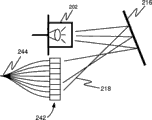
Fig. 5 A, 5B and 5C have described the optical sensor shell that comprises the light sensing system parts.
Fig. 6 A, 6B and 6C have described the optical sensor shell that comprises the light sensing system parts.
Fig. 7 A and 7B have described by the speckle pattern that light supply apparatus produced that comprises light source and waveguide.
Fig. 8 A and 8B have described by the speckle pattern that light supply apparatus produced that comprises light source and diffuser.
Fig. 9 A, 9B and 9C have described the implementation of the light sensing system that comprises the space dark slide.
Figure 10 A, 10B and 10C describe the implementation of the light sensing system that comprises the photo-detector with a plurality of light detecting areas.
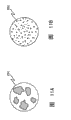
Figure 11 A, 11B and 11C describe the speckle pattern that a plurality of implementation produced by the life sign measurement device.
Figure 12 describes by photo-detector and receives the signal of telecommunication that the part through the synthetic speckle pattern of arterial pulse produces.
Figure 13 describes has the implementation that a plurality of light detecting areas and each light detecting area all produce the photo-detector of the signal of telecommunication.
Figure 14 A, 14B and 14C describe and are output the implementation that the unit is used for determining the different analytical methods of one or more vital signs.
Reference numeral identical in a plurality of accompanying drawings is represented components identical.
Describe in detail
As shown in fig. 1, the life sign measurement device comprises sensor fastening device 102, optical sensing system 104 and output unit 106.Can be used to determine the measurement result of vital sign from the output of light sensing system 104.Sensor fastening device 102 is suitable for placing against an anatomical position of experimenter 112, is exactly tremulous pulse 118 in this anatomical position.When sensor fastening device 102 against above-mentioned anatomical position of the experimenter 112 and when placing, light sensing system 104 can be oriented to the motion of sensing corresponding to arterial pulse.Light sensing system 104 comprises light source 202, anaclasis body 212,214 or 216 and photo-detector 240, and it is fixing by sensor fastening device 102 all, and with sensor fastening device 102 motions.Output unit 106 can receive the input of expression corresponding to the rich motion of tremulous pulse from light sensing system 104, and can produce a kind of measurement result of vital sign.Light sensing system 104 can be according to motion, bending or the compression with respect to the other parts of light sensing system of at least a portion of light sensing system, and---these motions, crooked or compression can cause being changed by the optical signal that photo-detector receives---comes the sensing tremulous pulse rich.
For example, vital sign can comprise the measurement result of heart rate, arterial pulse waveform, systolic pressure, diastolic pressure, mean arterial blood pressure, pulse pressure and/or arterial compliance.In some implementations, can determine vital sign according to the amplitude of the sequential of arterial pulse, arterial pulse and/or size or according to the arterial pulse waveform.In some implementations, can be separately according to the output that receives from light sensing system 104 or according to the combination (for example, the data of relevant pneumatic arm cover internal pressure) of this output and other data, determine vital sign.For example, in some implementations, can determine heart rate according to the output that receives from light sensing system 104 separately.
Sensor fastening device
Shown in Fig. 2 A, 2B and 2C, light sensing system 104 can be positioned at the midpoint (shown in Fig. 2 B and 2C) of near (shown in Fig. 2 A) mid point of sensor fastening device 102, sensor fastening device 102 or away from the mid point (not shown) of sensor fastening device 102.At the sensor fastening device 102 inner light sensing systems 104 of placing, can influence the data that obtained.In some implementations, it can be uneven being applied to the pressure that is positioned at the subsurface tremulous pulse of anatomical position.For example, though health apparatus for placing 102 can apply differential pressure, pass pressure that organized layer transmits and can cause differential pressure the tremulous pulse that is positioned at next segment distance of surface.In some implementations, the tremulous pulse institute applied pressure that is positioned at next segment distance of surface is overlapped the midline maximum at arm by inflatable arm cover, and less in arm cover edge.But fixed light sensing system 104 is with respect to the position of sensor fastening device 102, to optimize the sensitivity to the selected feature of arterial pulse.In some implementations, light sensor system 104 can be positioned at the center line of arm cover, so that it does not amplify in response to the pulsation of the artery segment below arm cover neighbouring part when arm cover pressure surpasses systolic pressure, thereby allow when open at the middle part of artery segment, can carry out accurately determining to systolic pressure.
In other implementation, light sensor system 104 can be positioned near the distal edge of arm cover, so that it is especially in response to the pulsation tremulous pulse change in size of this position.Therefore, the specific characteristic that distal position is in the arterial pulse waveform under the diastolic pressure can be identified at, and the influence of the arterial compliance in the tremulous pulse in distally more can be detected.During systole when arm cover pressure was lower than systolic pressure, the skin in arm cover midline and center line distally occurred outwardly-bent.As mentioned above, when arm cover pressure surpassed systolic pressure, the tremulous pulse vibration was limited in the near zone of arm cover.In some implementations, light sensing system 104 can be positioned at pressure and give on the isolating health fixture 102 of device, wherein this pressure gives device and is suitable for against experimenter's second anatomical position and places, second anatomical position approaches the above-mentioned anatomical position of sensor fastening device 102, gives the distally of device and gives device isolating position probing arterial pulse with pressure at pressure to allow light sensing system.For example, to give device can be inflatable arm cover to pressure.In some implementations, pressure gives device and health fixture 102 can be inflatable arm cover.
Thereby Fig. 2 A has described sensor fastening device 102 reaches minimum at systolic arterial pressure and the enough big tremulous pulse opening below the forward position of systole sensor fastening device 102 of this pressure that applied pressure on the arm has surpassed brachial artery.During arterial pulse, because the arteriectasia at place, forward position, the amount that heads on the pressure of sensor fastening device 102 will pulsed slightly.Place, location at light sensing system 104 the tremulous pulse opening can not occur, and therefore light sensing system 104 can not produce the signal of beating.Yet the situation that is positioned at the mid point of sensor fastening device 102 with light sensing system 104 is compared, if it is positioned near the mid point of sensor fastening device 102, more the signal of beating can occur under the high pressure.
Fig. 2 B describes sensor fastening device 102 and has applied pressure just over systolic arterial pressure, so that extend to the mid point that approaches sensor fastening device 102 at systole tremulous pulse opening 118.The vibration that heads on during the arterial pulse pressure in the pressure of sensor fastening device 102 will be more many greatly than the situation of Fig. 2 A, because arteriectasia all occurred at almost half of that section tremulous pulse that is positioned at sensor fastening device.But, the tremulous pulse opening do not occur, and therefore light sensing system 104 can not produce the signal of beating in sensor fastening device 102 midpoint.
Fig. 2 C describes sensor fastening device 102 and has applied pressure less than systolic arterial pressure, so that whole artery segment 118 is temporarily opened at systole.The vibration that heads on during arterial pulse in the pressure of sensor fastening device 102 will be bigger aspect amplitude.Tremulous pulse opening in the light sensing system lower position causes light sensing system to write down the signal of beating.
Fig. 3 describes an implementation of sensor fastening device 102.Sensor fastening device can be the inflatable arm cover 120 with inflatable air bag 122.Inflatable arm cover 120 can be adapted to wrap over around experimenter's the upper arm, with the arterial pulse that allows light sensing system 104 to detect from brachial artery.The parts of light sensing system 104 can be encapsulated in the optical sensor shell 200 at mid point 134 places that are positioned at arm cover 120.Arm cover 120 (for example can comprise hook and loop fasteners 132
) or other fixture, can be used to arm cover 120 is fixed on around experimenter's extremity.Arm cover 120 can be wrapped in around experimenter's the limbs, and air bag 122 is inflatable to give pressure on these limbs.Air bag 122 can be connected to pump 124 by flexible pipe 116.Air bag 122 can also be attached to the expansible valve 126 that can control air bag 122.But working pressure transducer 128 is measured the pressure in the air bag 122.As shown, pressure converter 128 can be arranged in air bag, or can pneumatically be connected to air bag 122 (for example by flexible pipe 116).
The top of Fig. 4 described the pressure that given when sensor fastening device 102 when the pressure that surpasses experimenter's systolic pressure reduces to the pressure that is lower than experimenter's diastolic pressure sensor fastening device 102 pressure pulse that gives by a series of arterial pulses of sensing.The bottom of Fig. 4 described the pressure that given when sensor fastening device 102 when the pressure that surpasses experimenter's systolic pressure reduces to the pressure that is lower than experimenter's diastolic pressure light sensing system 104 in the determined pulse of the midpoint of sensor fastening device 102.As shown, light sensing system 104 does not detect any pulse, is in or is lower than systolic pressure up to institute's applied pressure.In some implementations, this can allow systolic pressure is carried out accurately determining.
Output unit
Detected motion from light sensing system 104 can be sent to display device 114 by electric wire 108.In some implementations, as shown in Figure 3, electric wire 108 can be connected to display device 114 with pressure converter 128.Output unit 106 (not shown in Fig. 3) can be the part of display unit 114, can maybe can be positioned at a distance and by wireless transmission and communicate by letter with light sensing system 104 in another part of arm grip assembly in optical sensor shell 200 inside.In some implementations, output unit 106 can send the life sign measurement result by wireless transmission.In some implementations, light sensing system 104 can pass through wireless transmission, and the data of the relevant light quantity that received by photo-detector are sent to output unit 106.Output unit 106 can comprise processor, is used for being with or without definite vital sign under other data conditions according to the signal from light sensing system 104.In some implementations, as shown in Figure 1, output unit can comprise the display that is used for describing above-mentioned vital sign.In some implementations, output unit can comprise warning system, just produces human detectable signal when the life sign measurement result who is produced by output unit reaches this warning system of predetermined standard time.For example, output unit can be suitable for producing visual or audio alert has exceeded preset range with the warning vital sign that the user was detected.Output unit 106 can be finished a plurality of date processing, calculating or estimation function, and wherein some are discussed hereinafter.
Light sensing system
In some implementations, light sensing system 104 can comprise the light source 202 that couples light to anaclasis body 212,214 or 216, so that light wave advances to anaclasis body 212,214 or 216 from light source 202.Light source 202 can be coherent source, for example laser.In some implementations, LED can be used as light source 202.
In some implementations, the anaclasis body can be fiber waveguide 212, diffuser 214, reflecting mirror 216 or other refractive material with blemish.Anaclasis body 212,214 or 216 motion, bending or compression can change light wave 218 by fiber waveguide 212, by diffuser 214 advance path of being got or the path that reflects reflecting mirror 216, thereby cause the amount of photo- detector 240 or 242 luminous energy that received (for example light) to change.Similarly, the athletic meeting of light source 202 or photo- detector 240 or 242 causes being changed by the amount of photo- detector 240 or 242 light energies that received (for example light).By the quantitative change of the light energy that received of monitoring, the feature that can portray arterial pulse, it can be used to determine vital sign.For example, can determine the amplitude of pulse, maybe can determine the waveform shape of pulse.
In some implementations, photo- detector 240 or 242 can be PIN diode photo-detector, CCD (charge-coupled image sensor) detector or CMOS (complementary metal oxide semiconductors (CMOS)) detector.In some implementations, light sensing system 104 can comprise one or more photo-detectors 240 or 242.For example, in some implementations, a series of photo-detectors can receive respectively by anaclasis body 212,214 or 216 refractive luminous energy.In some implementations, photo-detector 242 can comprise a plurality of light detecting areas.For example, CCD and cmos detector can be configured to allow to survey amount, or can be configured to export the signal of the total amount that is used to represent the light energy that receives by CCD or cmos detector by a plurality of discrete light energies that detecting area received.
In some implementations, all as discussed below, light source 202 and anaclasis body 212,214 or 216 can be arranged to the generation speckle pattern.In some implementations, the compression of compressible or elasticity fiber waveguide and/or the change of the crooked light summation that can cause leaving fiber waveguide or the change of speckle pattern.
Fig. 5 A, 5B, 5C, 6A, 6B and 6C illustrate the example that can place against experimenter's skin with the microminiaturized optical sensor shell of sensing arterial pulse.As shown, optical sensor shell 200 comprises sensor mat 232, is attached to the spring 234, light source 202, anaclasis body 212,214 or 216, photo- detector 240 or 242 and from the electric wire 108 of photo-detector 240 of sensor mat 232.In some implementations, optical sensor shell 200 also can comprise other element, such as described among Fig. 5 C be in anaclasis body 212,214 or 216 and photo- detector 240 or 242 between space dark slide 222 (for example pin hole footpath).In some implementations, sensor outer housing 200 can have the thickness of (for example about 0.6 inch) between the length of (for example about 1.7 inches) between the width, 1.5 to 2.2 inches of (for example about 1 inch) between 0.7 to 1.3 inch and 0.3 to 0.9 inch.
As shown in Fig. 5 A, 5B, 5C, 6A, 6B and 6C, be suitable for against experimenter's a anatomical position and the sensor mat of placing 232 is attachable to spring 234.Sensor mat 232 may extend into outside the optical sensor shell 200 when being in relaxed state.For example, sensor mat 232 may extend at least 0.1 inch (for example, between 0.1 and 0.3 inch) outside the optical sensor shell 200.As shown, sensor mat 232 extends outward 0.161 inch from sensor outer housing 200.Sensor mat 232 can have arbitrary shape.Sensor mat 232 can have at least 0.3 inch diameter, for example (for example about 0.6 inch) between 0.3 and 0.8 inch.In some implementations, for example shown in Fig. 6 C, sensor mat 232 can be attached to spring 234 by hinge 236 and move back and forth to allow sensor mat 232.In some implementations, shown in Fig. 6 C, sensor mat 232 can have the upper surface of inclination.
Also sensor mat 232 can be positioned at one cuts out in the portion 252.The interval that cuts out between portion 252 and the sensor mat 232 can influence the amount that sensor outer housing 200 allows, makes sensor mat 232 motions because of arterial pulse.The interval that cuts out between portion 252 and the sensor mat 232 can be about 0.1 inch.
As mentioned above, electric wire 108 can be sent to output unit 106 from photo- detector 240 or 242 with data.In some implementations, output unit can be included in the optical sensor shell 200, and electric wire 108 can send to vital sign data the device in shell 200 outsides.(not shown) in some implementations, light sensing system 104 can send data from shell 200 by wireless transmission.
Speckle pattern
Fig. 7 A, 7B, 8A and 8B have described the synthetic ultimate principle of speckle pattern.Light source 202 can couple light to anaclasis body 212,214 or 216, so that light wave 218 marches to anaclasis body 212,214 or 216 from light source 202.Light source 202 can provide coherent light.Can use the light source 202 such as laser to illuminate anaclasis body 212,214 or 216 to produce " speckle pattern " 260, being referred to as " speckle pattern " is because this optical effect is speckle 262 to have occurred in the illumination of far field.For example, the anaclasis body can be fiber waveguide 212, diffuser 214, has the reflecting mirror 216 (for example shown in Fig. 9 C and 10C) of blemish, maybe can form another refractive material of speckle pattern 260.Refraction can cause the spatial variations of the light wave 218 that transmitted, and it shows as the dark space in the light background.These dark spaces or speckle 262 can have shape and size peculiar but at random, are determined by the refracting characteristic of anaclasis body 212,214 or 216.The light wave 218 (only illustrating wherein several) that illuminates anaclasis body 212,214 or 216 can constructive interference, with the speckle pattern 260 that forms a series of speckles 262.Anaclasis body 212,214 or 216 relative motioies with respect to light source 202, bending or compression have changed light wave 218 and have passed the path that anaclasis body 212 or 210 is advanced or got when reflecting refractile body 310, thereby cause speckle pattern 260 to change.For example, when anaclasis body 212,214 or 216 moved with respect to light source 202, it seems that speckle pattern 260 can glimmer, or rotation in some cases.Though selected probe portion for example 264 by the monitoring speckle pattern, pass that anaclasis body 212 or 210 is advanced or whole light of reflecting reflecting mirror 216 can keep relative stability, but the quantitative change that is detected light energy in the part 264 (for example light) of speckle pattern 260 can be observed.By for example 264 the variation that is detected light quantity in the part of monitoring, can determine the amount and/or the speed of relative motion, bending or compression.
Allow just can be limited and be detected part for example 264 by photo- detector 240 or 242 parts that receive by limiting formed speckle pattern 260.The restriction speckle pattern 260 by photo-detector 240 receive that part of, can realize in several ways.For example, shown in Fig. 9 A, 9B and 9C, the space dark slide 222 such as barrier structure with the optical aperture that is formed at wherein (for example pin hole footpath) can be positioned in anaclasis body 212,214 or 216 and photo-detector 240 between.In some implementations, have the photo-detector 240 of the luminous energy receiving area littler than speckle pattern 260 areas that produced by use, that can limit speckle pattern 260 is detected part 264.Can with employed photo- detector 240 or 242 and other intermediate space dark slides 222 be placed near anaclasis body 212 or 214, only for example receive light in 264 to guarantee photo- detector 240 or 242 from predetermined probe portion.When the reflecting mirror 216 that will have blemish uses as the anaclasis body, employed photo-detector 240 and any intermediate space dark slide will determine the size of probe portion 264 and the speckle pattern 260 that is produced.
The anaclasis body can be fiber waveguide 212, diffuser 214 or have the reflecting mirror 216 of blemish, maybe can form another refractive material of speckle pattern 260.In some implementations, a kind of device can use a plurality of and/or the different optical combination of elements.For example, fiber waveguide 212 can be used for light wave 218 is guided to diffuser 214.
θ
c=arcsin(n
1/n
h)
In some implementations, the encirclement material that has than low-refraction can be an air.In some implementations, waveguide also can be the form with hollow pipe of high reflective inner surface.Inner surface can be the metal through polishing.
In some implementations, shown in Fig. 7 A and 7B, fiber waveguide 212 causes the internal reflection of light wave 218 at the in-core of fiber waveguide 212.When fiber waveguide 212 moved or be crooked, the path of each light wave 115 will change, and causes the gained speckle pattern to change.In some implementations, fiber waveguide 212 can be resilient waveguide.In some implementations, fiber waveguide 212 can be compressible waveguide.


In some implementations, shown in Fig. 8 A and 8B, diffuser 214 causes the intravital light wave refraction of the master of diffuser 214.The intravital light wave refraction of diffusion can be caused by the variations in refractive index---this variation can cause photon scattering at random---in the diffuser 214.When diffuser 214 motion, diffuser causes that the refractive zone of light wave also can move, and causes light wave 218 differently refraction in diffuser 214, causes the variation of gained speckle pattern 260.
In some implementations, shown in Fig. 9 C and 10C, optical element also can be the reflecting mirror 216 with blemish.The light wave that defective in the reflecting mirror can cause shining on the defective reflects with different angles.The light that reflects from the reflecting mirror 216 with defective also can cause optical design 260.Reflecting mirror 216 can cause the variation of optical design 260 equally with respect to the relative motion of light source 202.
In some implementations, the feature sizes of single speckle 262 and quantity can be controlled.For example, can utilize fiber waveguide 212 that the feature sizes and the quantity of single speckle 262 are controlled to be the speckle characteristics 125 that needs with optimum diameter and refracting characteristic.Figure 11 A and be from laser 202 speckle pattern 260 of---its light beam passes different optical fiber---shown in the 11B.In Figure 11 A, show speckle pattern with few relatively big speckle 262, form the fiber waveguide 212 that it is little from diameter and refractive index gradient is little.On the contrary, thus the speckle pattern 260 with much more relatively little speckles 262 shown in Figure 11 B is to utilize because the fiber waveguide 212 that allows more interference of light to cause having relative many little speckle 262 with big refractive index gradient than major diameter forms.
Equally, Figure 11 C is by making coherent light pass the amplification of the speckle pattern 260 that diffuser 214 forms.The size of amplifying is represented in the bar shaped on right side on the figure.
In some implementations, the average speckle size of speckle pattern 260 sampling part can be at least 10 microns (for example, between 25 and 100 microns).
Size by correctly determining probe portion 264 and fixed light refractile body 212,214 or 216, photo-detector 240 and the separation case of intermediate space dark slide 222 (if use) arbitrarily can be optimized the sensitivity of relative motion, bending or compression to light source and anaclasis body 212,214 or 216.Can determine the size of probe portion 264 with respect to average speckle size, with the fluctuating margin in the electricity output of optimizing photo-detector 240, the modulation of the speckle pattern 260 that it causes corresponding to relative motion, bending or compression by anaclasis body 212,214 or 216, light source 202 or photo-detector 240 or 242.For example, only collect a small amount of speckle by the pore size of determining space dark slide 222, such as being less than 1% of speckle pattern 260 areas, and utilize to the time become the appropriate signal that photo-detector output done and handle, the time-derivative that just can measure pulse signal is to allow the calculating vital sign.In some implementations, the area of the luminous energy receiving unit of photo-detector 240 can also be less than the area of the speckle pattern 260 that is produced.
In some implementations, the probe portion 264 of speckle pattern 260 can be average speckle size less than 100 times, between 1 and 25 times of for example average speckle size.In some implementations, photo-detector 240 can receive average 50 speckles at most, for example between 1 and 5 speckle.For example, can use pin hole directly to limit speckle pattern 260 by photo- detector 240 or 242 probe portions 264 that receive with 125 micron diameters.
Analytical method
The photo-detector 240 of light sensing system 104 or 242 can produce the signal of telecommunication 420 of the expression light quantity that receives.The signal of telecommunication 420 can be the function of time.Analyze electro-optical detector signal 420 to determine the modulation rate of speckle pattern 260.For example, Figure 12 has described a kind of possible signal of telecommunication 420, is used to represent the modulation by the amount of photo- detector 240 or 242 light energies that receive.As shown in figure 12, the light quantity that is received by photo-detector 240 can be vibrated.Generally the frequency of oscillation of the light energies that received by photo- detector 240 or 242 can be interpreted as the inverse of that time quantum of the quantity of the speckle in the predetermined probe portion (for example 264) or the variation of brightness occurrence characteristics, these speckles are received by photo-detector 240 or 242.Generally the characteristic that occurs in the quantity of speckle or the brightness can be changed in proportion and draw, with distinctive relative motion, bending between expression light source and the anaclasis body or compress.By monitoring the oscillation rate of the light quantity that is received by photo-detector 240, can determine the amplitude and/or the size of arterial pulse.
In some implementations, the average light quantity that is received by photo-detector 240 can change with respect to the location of anaclasis body 212,214 or 216 in time in response to light source, and the light quantity that is received by photo-detector 240 can be that the center vibrates up and down with the average light quantity that is received because of the relative motion of light source and anaclasis body.
In some implementations, can be with this low frequency variations filtering from the signal that is received of the light quantity that received.In some implementations, can be with high frequency " noise " filtering.In some implementations, before determining vital sign from data, height in the light quantity that can be received by photo-detector and/or low frequency variations are from from filtering the signal of photo-detector 240 or 242.In some implementations, can finish signal filtering by light wave shape prefilter 432.
Output unit 106 can determine that the amplitude of each arterial pulse and/or size are to determine one or more vital signs.In some implementations, can determine that the amplitude of a series of arterial pulses and/or size are to determine one or more vital signs.For example, in order to determine the amplitude and/or the size of arterial pulse according to the vibration of the light quantity that receives by photo-detector 240, peaker can be applied to photo-detector 240 outputs and go up to produce and the proportional signal of its time derivative dE/dt.This time derivative signal can with the proportional increase of the frequency component of the photo-detector signal of telecommunication---modulation rate of this frequency component and speckle pattern is proportional---.Each arterial pulse (corresponding to cardiac cycle) for example presents to characteristic pressure and increases, and then pressure reduces, and is resting stage before next pulse begins then.The pressure increase can cause light source 202 motions or anaclasis body 212,214 or 216 motions, bending or compression so that speckle pattern 260 modulation, modulation rate begins the place at pulse and increases, and is reduced to zero in moment of maximum pulse pressure (be pulse wave top out and be about to begin its decay).When pressure reduced, the adverse movement of waveguide will occur, and modulated speckle pattern once more so that its modulation rate increases after maximum pulse pressure, and was reduced to zero when arterial pulse finishes.Figure 12 has described the example of the photo-detector signal of telecommunication that is produced by arterial pulse.Therefore signal dE/dt will begin from zero, increase to maximum then, be reduced to zero again, and then will increase, and finally be reduced to zero, and all these are all during an arterial pulse process.As first approximate, pulse magnitude can be proportional with maximum speckle modulation speed, and maximum speckle modulation speed can be calculated based on the relation between SIN function and the derivative thereof according to the maximum of dE/dt, that is:
dE/dt=d/dt[sin(ωt)]=ω·cos(ωt),
Its amplitude peak and maximum modulation speed or ω during the arterial pulse cycle
MaxProportional.
Can utilize the real-time spectrum analyzer such as digital signal processor (DSP) to come analytic signal dE/dt, with the peak frequency during definite arterial pulse cycle.Peak frequency ω
MaxOccur at dE/dt maximum place, and proportional with pulse magnitude in the same way.Can be with the highest dominant frequency ω
MaxBe used for analyzing,, can use first, second or other instantaneous value of frequency spectrum so if perhaps provided frequency range.
Photo-detector 240 outputs also can be that AC is coupled, and be fed in zero crossing (zero-crossing) detector, it will provide the counting (" zero crossing rate ") of time per unit zero crossing incident and the grand total (" zero crossing counting ") of the zero crossing incident during arterial pulse.By correctly limiting the size of probe portion 264, the modulation rate that instant zero crossing rate and speckle pattern 260 can easily be shown is proportional.But uses algorithm is surveyed the rising of zero above zero crossing rate, then the quantity of zero crossing rate is counted, and returns zero up to the zero crossing rate.Can use slightly to replace real zero crossing rate, with resolution system " noise " above zero threshold value.Perhaps, can be with high-frequency noise from from filtering the signal of photo-detector 240 or 242.After the zero crossing rate rises above zero once more, but repeat count returns zero up to it.This cycle and arterial pulse of twice zero crossing counting of comprising is mapped.Two countings of average together this can be proportional with the waveguide amplitude that interrelates with arterial pulse, thereby can be proportional with the arterial pulse amplitude.Can be with an algorithm application to this zero crossing rate, this speed of this algorithm measurement remains on the incident at the zero point between the non-zero scene.In an arterial pulse sequence, the relative time than length between the ending of arterial pulse and next beginning can appear.Pressure tops out and the relative short period can appear in the maximum pulse pressure place that begins to reduce therein, and wherein the zero crossing rate can instantaneously be zero.
In some implementations, can make signal dE/dt by integrating circuit, and with it from time integral being returned zero point up to it greater than beginning zero point.This time is corresponding to the half period of arterial pulse, and the time average that it can be by independent measurement dE/dt is to determine it and when deviate from and to return zero point and determine.The amplitude of the integrated value of gained and waveguide vibration is proportional, thereby also proportional with the arterial pulse amplitude.First derivative of experimenter position to the integrated value of special time period can produce with special time period during the proportional result of change in location.
In some implementations, shown in Figure 10 A, 10B and 10C, can use a plurality of light detecting areas 244.These light detecting areas 244 can be the parts of photo-detector 242, and it has comprised a plurality of discrete light detecting areas 244.For example, photo-detector 242 can be CCD (charge-coupled image sensor) or CMOS (complementary metal oxide semiconductors (CMOS)) detector.Each light detecting area 244 can be configured to only receive the restricted part of the speckle pattern 260 shown in for example Figure 10 A, 10B and the 10C.Use a plurality of light detecting areas 244, can obtain to represent more reliably the data of the relative amplitude of a series of pulse pressure waveforms.In some implementations, from the output of a plurality of light detecting areas 244 AC coupling and be fed to zero crossing detector respectively.Can so that determining, which have highest signal quality in ending place of each arterial pulse or at ending place the signal of telecommunication 420 more as shown in Figure 13 in each blood pressure measurement cycle corresponding to different light detecting areas 244.Can count to determine the quality of the signal of telecommunication 420 by the zero crossing that detects each signal.For example, can think to have that the signal of telecommunication 420 of high counting has highest signal quality.Also can average each arterial pulse is produced more reliable pulse magnitude assessment to each different zero crossings counting of different detectors (or subclass of different detectors).
In some implementations, can be coupled to peaker respectively to measure dE/dt from the output of a plurality of photo-detectors.Can the ending of each arterial pulse or in the ending in each blood pressure measurement cycle relatively corresponding to the different dE/dt values of different detectors, with definite which have highest signal quality.For example, can think to have peak dE/dt
MaxThat have highest signal quality.Also can be to averaging corresponding to a plurality of different dE/dt values of different detectors (or subclass of different detectors) each arterial pulse is produced more reliable pulse magnitude assessment.
In some implementations, CCD (charge-coupled image sensor) or CMOS (complementary metal oxide semiconductors (CMOS)) detector can be used as single photo-detector 240 or are used as a plurality of light detecting areas 244.Typical C CD or cmos detector can have and surpass 1 mega pixel, and digital cameras in general use can have in 1-2 centimetre rectangular sensor up to 800 ten thousand or more pixels.Each pixel, or independent addressable sensing area can be used as independently optical detection district 244.Also can use " binning (binning) " to increase detector sensing area effectively by combination N * M group (for example, 2 * 2,2 * 3,3 * 3 etc.) pixel.In some implementations, can dynamically regulate the size of the probe portion 264 of light detecting area 244 by " binning ".For example, during sensor life-time, anaclasis body 212,214 or 216 optical characteristics can change, and the size of dynamically regulating " through binning " pixel groups at the life period of light sensing system 104 is to optimize the size of probe portion 264 again.In some implementations, as respectively the organizing pixel and can have identical or different size of light detecting area 244, it can be optimized by the part that this group pixel receives according to speckle pattern 260.The use of CCD or CMOS photo-detector 240 or 242 can allow not to be placed on the device of the optical aperture between optical element and CCD or the CMOS photo-detector, and (diagonal is the 2-5 micron usually) causes the volitional check to the area of the probe portion 264 of speckle pattern 260 because the small size of CCD and cmos pixel.
In some implementations, a plurality of CCD or cmos detector can be arranged in single pixel or through 1 * N array of the combination of pixels of binning.For example, Figure 10 A, 10B and 10C have described 1 * 8 array and Figure 13 has described 1 * 4 array.And, as shown in figure 13, can carry out Digital Signal Processing to each of the independent numeral output 420 of N.Each numeral output 420 can comprise by 244 observations of each light detecting area, about the synthetic information of the optical figuring in the different probe portions 264 of speckle pattern 260.Each Digital Signal Processing analysis can provide the real-time estimation to the modulation rate in one of detecting area, and can be used for the maximum modulation speed during definite each arterial pulse.Can be each arterial pulse averages to produce paired pulses amplitude and the more reliable estimation of pulse amplitude envelope to N measurement.
In the implementation of using CCD or CMOS photo-detector 240 or 242 (as single photo-detector or as a plurality of detectors), the average light level detector output can be set and it be defined as " threshold value ".Can measure single detector signal (per second is 100-2000 time usually) fully continually in the hope of separating the speckle pattern modulation.The truthful data rate depends on respect to the feature speckle size of detector area and the optical element movement velocity about light source.Be defined as detector output measure with threshold value between each threshold crossings of opposite with the difference polarity between the threshold value appearance of difference with detector measurement subsequently can be corresponding to " zero crossings ".Can analyze to the threshold crossings counting and according to the mode that is equivalent to above-mentioned zero crossings counting.
In some implementations, can use digital signal processor (DSP) to analyze output from one or more photo-detectors 240 or 244.Can use multiple Digital Signal Processing analytical method and determine modulation rate, include but not limited to fast Fourier transform (FFT), self correlation and threshold crossings the numeral output of CCD or CMOS.
In fft analysis, can be by following Algorithm Analysis signal to determine average frequency:
<ω>=∫ω·G(ω)dω,
Wherein ω is an angular frequency, and G (ω) is a power spectrum, and ∫ (ω) d ω is normalized to 1.
G (ω) determines by following known convolution:
G(ω)=[∫g(t)·exp(-jωt)dt]
2,
Wherein g (t) is time dependent signal or the output of photo-detector in the case E.
During each arterial pulse,<ω〉value can increase pro rata with previously described signal dE/dt and reduce.Therefore,<ω 〉
MaxValue can represent maximum modulation speed in the given arterial pulse cycle, and can draw in proportion and be used for producing and be used for the pulse magnitude envelope of determining that systolic pressure, diastolic pressure and average pulse are pressed.
In some implementations, can use autocorrelation method to determine pulse magnitude and pulse magnitude envelope.In self correlation, signal can carry out self correlation according to following relation:
<G(τ)>=∫g(t)·g(t-τ)dt,
Wherein G (τ) is the auto-correlation function when time delay equals τ, and g (t) is a variable signal in time.The value of G (0) equals the mean square of signal amplitude.Frequency spectrum is the convolution of auto-correlation function simply, so:
G(ω)=(1/2π)·∫G(τ)·exp(-jωτ)dτ.
The previous description uses autocorrelation method to determine the average frequency of variable signal in time, no longer further specifically provides here.This that uses G (ω) calculate according to fft analysis in the same formula calculating average frequency:
<ω>=∫ω·G(ω)dω
In some implementations, at the pressure in blood pressure arm cover during the interval when the horizontal stable that is higher than systolic pressure that does not wherein have arterial pulse reduces, be that arterial pulse calculates the maximum of dE/dt each time.During this interval, increase the beginning that detects each pulse by the periodicity of measuring and write down dE/dt.For each pulse, the dE/dt maximum can be recorded as dimensionless number, the vertical coordinate of chart is dE/dt to allow wherein but also can write down arm cover pressure
MaxRather than with mmHg the generation of pulse magnitude envelope of the amplitude of unit.Can be with algorithm application in this envelope to determine systolic pressure, diastolic pressure, pulse and/or mean arterial pressure.
In some implementations, can count the zero crossing number of the coupled photo-detector output of AC during the interval when the horizontal stable that is higher than systolic pressure that does not wherein have arterial pulse reduces when the pressure in the inflatable arm cover 120.A series of arterial pulses can be detected during the interbody spacer at this moment, and the zero crossings counting of each pulse can be measured and write down.For each pulse, can write down this counting meansigma methods of two countings of the rising of arterial pulse and decline (or corresponding to), also can write down arm cover pressure so that to allow the vertical coordinate of chart wherein be the zero crossings counting rather than be the generation of pulse magnitude envelope of the amplitude of unit with mmHg.Can be with algorithm application in this envelope to determine systolic pressure, diastolic pressure, pulse and/or mean arterial pressure.
In some implementations, the interval between the pulse can be measured during a series of detection arterial pulses, and can be used to determine heart rate.
In some implementations, when arm cover pressure reduces, systolic pressure can be defined as the pressure at the inflatable arm cover 120 of speckle pattern modulation appearance place for the first time (promptly surpassing the rising of zero crossing rate at zero point or the nonzero value of dE/dt occurs for the first time).In some implementations, diastolic pressure can be defined as the pressure at the inflatable arm cover 120 of predetermined modulation characteristic appearance place of speckle pattern.For example, zero crossing rate wherein can be had nonzero value at last, or wherein last nonzero value of dE/dt occurs, and the dE/dt arterial pulse that remains the zero last detection that further increases of arm cover pressure is simultaneously thought diastolic pressure afterwards.Or dE/dt wherein
MaxValue be dE/dt
MaxIn the arterial pulse sequence of 50% decline of maximum (being the peak on the pulse magnitude envelope) the first time arterial pulse appearance.In some implementations, mean arterial pressure can be defined as maximum zero crossing counting or dE/dt occurring corresponding to its place
MaxThe pressure of the inflatable arm cover 120 of peaked arterial pulse incident.
In some implementations, can calculate anthropic factor in the arterial pulse and other anthropic factor relevant with the speckle pattern modulation to the contribution of light sensing system 104 and the algorithm that empirically is determined based on a kind of, systolic pressure is calculated as has been lower than at the arm cover pressure of arm when the speckle pattern modulation occurs for the first time between the cover phase of expansion with electrical noise.
In some implementations, can be based on having calculated anthropic factor in the arterial pulse, and other anthropic factor is calculated as diastolic pressure the arm cover pressure that is higher than when the synthetic predetermined properties of speckle pattern occurs to the respective algorithms of the contribution of light sensing system 104.
In some implementations, determine the base line measurement (" baseline ") of blood pressure measurement, and estimate follow-up blood pressure measurement based on the continuous monitoring of vital sign.For example, use is aforesaid by dE/dt
MaxOr the relative pulse magnitude of a series of pulses that measurement obtained of zero crossing counting and use a photo-detector 240, a plurality of light detecting area 244, ccd sensor array or cmos sensor array can realize that baseline blood pressure reads.Sensor fastening device 102 can be adjusted to stress level then with known (according to the described blood pressure measurement of having finished) pulse magnitude (" reference amplitude "), but continuous measurement arterial pulse amplitude and with its with make comparisons with reference to the accompanying drawings.Utilize suitable algorithm to use to be different from any follow-up pulse magnitude measures of reference amplitude to measure the variation of blood pressure quantitatively with respect to baseline.In this embodiment, the main purpose of the method is monitored the variation of blood pressure with respect to baseline value continuously or periodically.In some implementations, can determine the baseline blood pressure measurement by other standard method such as auscultation method.
In some implementations, can determine the form of pulse wave by the changing value in time of measuring dE/dt.The form that can represent pulse wave by dE/dt in the whole pulse process to the curve of time.Perhaps can use time dependent zero crossing rate, or the threshold crossings rate in digital CCD or the CMOS detection system.
In some implementations, shown in Figure 14 A, 14B and 14C, output unit 106 can be determined vital sign by one or more of technology described above.For example, output unit 106 can be determined the size and/or the waveform of the one or more arterial pulses in the waveform generator 436.In some implementations, output unit 106 can comprise based on amplitude, size and/or the waveform determined and be applied to the systolic pressure waveshape detector that pressure (for example, by pressure transducer detected pressure in inflatable arm cover) that the experimenter can be detected is determined experimenter's systolic pressure.In some implementations, output unit 106 can comprise based on amplitude, size and/or the waveform determined and be applied to the diastolic pressure computer that pressure (for example, by pressure transducer 128 detected pressure in inflatable arm cover) that the experimenter can be detected is determined experimenter's diastolic pressure.In some implementations, heart rate computer 446 can be according to the arterial pulse waveform of determining from optical signal or according to determining heart rate by pressure transducer 128 detected pressure in inflatable arm cover.In some implementations, output unit 106 can comprise pulse wave sequential detector 434, and it can be guaranteed by light sensing system 104 detected each arterial pulse corresponding to the pulse that is detected by inflatable arm sleeve pressure sensor 128.In some implementations, pulse wave sequential detector 434 is provided to waveform generator 436 with data, determines and the consistent waveform of pulse that is detected by inflatable arm sleeve pressure sensor 128 to guarantee each waveform generator 436.
In some implementations, shown in Figure 14 C, output unit 106 can be amplitude, size and/or the waveform of each light detecting area 244 definite one or more arterial pulses in a series of waveform generators 436.In some implementations, output unit 106 can comprise and is used for the waveform comparator 438 of more a plurality of amplitudes, size and/or waveform.Waveform comparator 438 can be selected better light detecting area, on average from the signal of two or more light detecting areas, or based on from the single amplitude of the data computation of a plurality of light detecting areas 244, size and/or waveform.In some implementations, heart rate computer 446 can be according to from the single waveform of waveform comparator 438 from optical signal, or according to determining heart rate by pressure transducer 128 detected pressure in inflatable arm cover.
A plurality of realizations have been described.Yet, be to be understood that under the situation that does not deviate from spirit and scope of the invention and can make multiple modification.Therefore, other is realized also within the scope of appended claims.
Claims (14)
1. life sign measurement device comprises:
Sensor fastening device is suitable for against experimenter's a anatomical position and places, and is tremulous pulse in described anatomical position;
Light sensing system, described light sensing system comprises light source, anaclasis body and photo-detector, it is fixed by described sensor fastening device all, wherein, described light sensing system when described sensor fastening device against described experimenter's anatomical position and when placing sensing corresponding to the motion of arterial pulse, and described light sensing system sensing is by the arterial pulse on the change in optical signal of described photo-detector reception;
Output unit, described output unit receive from described light sensing system and are used to represent corresponding to the input of the motion of arterial pulse and use described input to produce the measurement result of vital sign,
Wherein, described anaclasis body is elasticity and/or compressible waveguide; And
The change in optical signal that is received by described photo-detector is by motion, bending of at least a portion of described elasticity or compressible waveguide or compresses and cause.
2. life sign measurement device as claimed in claim 1 is characterized in that, described sensor fastening device is inflatable arm cover.
3. life sign measurement device as claimed in claim 1 or 2, it is characterized in that, also comprise the pressure transducer that is used for detecting the pressure that is applied to described anatomical position, wherein said output unit receives the pressure input that is used to represent be applied to the pressure of described anatomical position from described pressure transducer, and wherein said output unit uses input and the described pressure input from described light sensing system to produce vital sign.
4. life sign measurement device as claimed in claim 1 or 2 is characterized in that, described light source and described anaclasis body are configured to produce speckle pattern output.
5. life sign measurement device as claimed in claim 4, it is characterized in that, described photo-detector is oriented to survey the part of described speckle pattern output, and produces the signal that is used to be illustrated in the luminous energy that is received in the probe portion of described speckle pattern output in view of the above.
6. life sign measurement device as claimed in claim 5 is characterized in that, described light sensing system also comprises space dark slide assembly, is used to prevent that described photo-detector from receiving the part of described speckle pattern output.
7. life sign measurement device as claimed in claim 5 is characterized in that, described photo-detector comprises the luminous energy receiving unit of surface area less than described speckle pattern output.
8. life sign measurement device as claimed in claim 7 is characterized in that, the surface area of described luminous energy receiving unit be average speckle size less than 100 times.
9. life sign measurement device as claimed in claim 1 or 2 is characterized in that described light source is a coherent source.
10. life sign measurement device as claimed in claim 1 or 2 is characterized in that, described vital sign is at least a in heart rate, arterial pulse waveform, systolic pressure, diastolic pressure, mean arterial blood pressure, pulse pressure and the arterial compliance.
11. life sign measurement device as claimed in claim 1 or 2 is characterized in that, the signal of the optical signal that described output unit is used to represent that described photo-detector receives produces the measurement result of vital sign.
12. life sign measurement device as claimed in claim 1 or 2, it is characterized in that, described light sensing system is configured to detect the optical signal that is used to represent a series of arterial pulses, and described output unit is applicable to the pulse wave of determining each arterial pulse in these a series of arterial pulses.
13. life sign measurement device as claimed in claim 1 or 2, it is characterized in that, also comprise and being suitable for against experimenter's anatomical position and the sensor mat of placing, be attached to the spring of described sensor mat, from the electric wire of described photo-detector, and comprise described sensor mat, described spring, from the optical sensor shell of the electric wire of described photo-detector and described light source, described anaclasis body.
14. life sign measurement device as claimed in claim 13 is characterized in that, described sensor mat comprises the pressing part of the bending, compression or the motion that are suitable for causing described fiber waveguide.
Applications Claiming Priority (7)
| Application Number | Priority Date | Filing Date | Title |
|---|---|---|---|
| US80281006P | 2006-05-24 | 2006-05-24 | |
| US60/802,810 | 2006-05-24 | ||
| US87466506P | 2006-12-13 | 2006-12-13 | |
| US60/874,665 | 2006-12-13 | ||
| US89826907P | 2007-01-31 | 2007-01-31 | |
| US60/898,269 | 2007-01-31 | ||
| PCT/US2007/069545 WO2007140210A2 (en) | 2006-05-24 | 2007-05-23 | Optical vital sign detection method and measurement device |
Related Child Applications (1)
| Application Number | Title | Priority Date | Filing Date |
|---|---|---|---|
| CN2010106236486A Division CN102144917A (en) | 2006-05-24 | 2007-05-23 | Optical vital sign detection method and measurement device |
Publications (2)
| Publication Number | Publication Date |
|---|---|
| CN101484069A CN101484069A (en) | 2009-07-15 |
| CN101484069B true CN101484069B (en) | 2011-02-23 |
Family
ID=38683500
Family Applications (2)
| Application Number | Title | Priority Date | Filing Date |
|---|---|---|---|
| CN2007800252829A Expired - Fee Related CN101484069B (en) | 2006-05-24 | 2007-05-23 | Optical vital sign detection method and measurement device |
| CN2010106236486A Pending CN102144917A (en) | 2006-05-24 | 2007-05-23 | Optical vital sign detection method and measurement device |
Family Applications After (1)
| Application Number | Title | Priority Date | Filing Date |
|---|---|---|---|
| CN2010106236486A Pending CN102144917A (en) | 2006-05-24 | 2007-05-23 | Optical vital sign detection method and measurement device |
Country Status (13)
| Country | Link |
|---|---|
| US (3) | US8343063B2 (en) |
| EP (2) | EP2462864B1 (en) |
| JP (1) | JP2009538210A (en) |
| KR (1) | KR101487372B1 (en) |
| CN (2) | CN101484069B (en) |
| AU (1) | AU2007267633B2 (en) |
| BR (1) | BRPI0712467B8 (en) |
| CA (1) | CA2653228C (en) |
| HK (1) | HK1129291A1 (en) |
| MX (1) | MX2008014932A (en) |
| MY (1) | MY149119A (en) |
| TW (1) | TWI429418B (en) |
| WO (1) | WO2007140210A2 (en) |
Families Citing this family (43)
| Publication number | Priority date | Publication date | Assignee | Title |
|---|---|---|---|---|
| WO2007140210A2 (en) | 2006-05-24 | 2007-12-06 | Tarilian Laser Technologies, Limited | Optical vital sign detection method and measurement device |
| US20080071180A1 (en) * | 2006-05-24 | 2008-03-20 | Tarilian Laser Technologies, Limited | Vital Sign Detection Method and Measurement Device |
| BRPI0721198B8 (en) * | 2007-01-31 | 2021-06-22 | Tarilian Laser Tech Limited | optical motion detection device and vital sign measuring device comprising the same |
| US8577431B2 (en) | 2008-07-03 | 2013-11-05 | Cercacor Laboratories, Inc. | Noise shielding for a noninvasive device |
| US8630691B2 (en) | 2008-08-04 | 2014-01-14 | Cercacor Laboratories, Inc. | Multi-stream sensor front ends for noninvasive measurement of blood constituents |
| EP2410570B1 (en) | 2009-03-19 | 2016-01-27 | LG Chem, Ltd. | Solar cell back sheet including a fluorine-based copolymer, and method for manufacturing same |
| KR101065615B1 (en) * | 2009-08-27 | 2011-09-20 | 한국전기연구원 | Pulse wave measuring apparatus using laser speckle image and Pulse wave measuring method using this apparatus |
| CN102210585A (en) * | 2010-04-06 | 2011-10-12 | 魏蔚 | Medical monitoring method and device for measuring blood flow signal of body surface artery |
| JP5883018B2 (en) | 2010-10-27 | 2016-03-09 | ザ ジェネラル ホスピタル コーポレイション | Apparatus, system, and method for measuring blood pressure within at least one blood vessel |
| US10366255B2 (en) * | 2011-01-06 | 2019-07-30 | Koninklijke Philips Electronics N.V. | Barcode scanning device for determining a physiological quantity of a patient |
| US20120250022A1 (en) * | 2011-04-01 | 2012-10-04 | X-Rite Europe Gmbh | Hand-Held Color Measurement Device |
| US8747328B2 (en) | 2011-04-29 | 2014-06-10 | Raytheon Bbn Technologies Corp. | Continuous blood pressure monitoring |
| KR101288391B1 (en) * | 2012-03-08 | 2013-07-22 | 주식회사 유메딕스 | Method for measuring blood pressure and apparatus thereof |
| CN102722251A (en) * | 2012-06-15 | 2012-10-10 | 哈尔滨工业大学深圳研究生院 | Multimedia feedback control system based on physiological signals |
| JP6251997B2 (en) * | 2012-09-18 | 2017-12-27 | カシオ計算機株式会社 | Pulse data detection device, pulse data detection method, and pulse data detection program |
| MX360972B (en) * | 2013-02-13 | 2018-11-23 | Leman Micro Devices Sa | Non-invasive blood analysis. |
| CN108565205B (en) * | 2013-03-15 | 2022-09-27 | 鲁道夫技术公司 | Photoacoustic substrate evaluation system and method |
| CN103300840B (en) * | 2013-06-28 | 2015-01-14 | 王颖 | Blood pressure measurement device for voyage |
| CN103349546A (en) * | 2013-07-16 | 2013-10-16 | 吕品 | Device and method for measuring pulse waves and blood pressures |
| KR102299361B1 (en) * | 2014-09-03 | 2021-09-07 | 삼성전자주식회사 | Apparatus and method for monitoring blood pressure, wearable device having function of blood pressure monitoring |
| WO2016037991A1 (en) | 2014-09-09 | 2016-03-17 | Koninklijke Philips N.V. | Vital signs monitoring system |
| US10206576B2 (en) | 2014-09-10 | 2019-02-19 | Samsung Electronics Co., Ltd. | Laser speckle interferometric system and method for mobile devices |
| US10694960B2 (en) * | 2014-09-29 | 2020-06-30 | Microsoft Technology Licensing, Llc | Wearable pulse pressure wave sensing device |
| RU2703638C9 (en) | 2014-10-02 | 2019-11-25 | Конинклейке Филипс Н.В. | Optical sensor of vital signs |
| KR102411658B1 (en) | 2015-01-15 | 2022-06-21 | 삼성전자주식회사 | Apparatus for detecting information of the living body |
| KR102384225B1 (en) | 2015-03-06 | 2022-04-07 | 삼성전자주식회사 | System and method for sensing blood pressure |
| EP3282935A1 (en) * | 2015-04-15 | 2018-02-21 | Koninklijke Philips N.V. | Optical laser speckle sensor for measuring a blood perfusion parameter |
| KR102434701B1 (en) | 2015-09-01 | 2022-08-22 | 삼성전자주식회사 | Apparatus and method for acquiring bio- information and apparatus for detecting bio- information |
| JP6928906B2 (en) * | 2016-01-07 | 2021-09-01 | パナソニックIpマネジメント株式会社 | Biological information measuring device |
| US11045103B2 (en) | 2016-04-28 | 2021-06-29 | Samsung Electronics Co., Ltd. | Physiological parameter detecting apparatus and method of detecting physiological parameters |
| GB201608170D0 (en) * | 2016-05-10 | 2016-06-22 | Isis Innovation | A method of determining the frequency of a periodic physiological process of a subject, and a device and system for determining the frequency |
| RU2648029C2 (en) * | 2016-08-10 | 2018-03-21 | Самсунг Электроникс Ко., Лтд. | Device and method of blood pressure measurement |
| KR102655671B1 (en) | 2016-10-12 | 2024-04-05 | 삼성전자주식회사 | Apparatus and method for estimating bio-information |
| CN106955092B (en) * | 2017-03-31 | 2021-02-23 | 北京信息科技大学 | Method and equipment for measuring pulse distribution |
| US11050931B2 (en) | 2017-05-16 | 2021-06-29 | Sony Corporation | Control device and control method |
| CN107638167A (en) * | 2017-08-18 | 2018-01-30 | 成都斯斐德科技有限公司 | Based on systolic pressure and the vision of pulse frequency coherence induction motion sickness detection method |
| CN107468222A (en) * | 2017-09-15 | 2017-12-15 | 王庆亚 | High-precision fast-response dynamic 3 D pulse detector |
| US20210361177A1 (en) | 2018-02-06 | 2021-11-25 | Huma Therapeutics Limited | Non-Invasive Continuous Blood Pressure Monitoring |
| RU2675066C1 (en) * | 2018-02-26 | 2018-12-14 | Федеральное государственное бюджетное учреждение науки Институт радиотехники и электроники им. В.А. Котельникова Российской академии наук | Monolithic three-chamber pneumatic sensor with integrated throttle channels for continuous non-invasive measurement of arterial pressure |
| CN112512416A (en) * | 2018-09-27 | 2021-03-16 | 湖南帕斯沃生物科技有限公司 | Device and method for automatic identification of Korotkoff sounds and/or bioacoustic signals using an optical stethoscope |
| CN110174200A (en) * | 2019-06-14 | 2019-08-27 | 安徽华米信息科技有限公司 | Pressure-detecting device, terminal |
| CN110432880B (en) * | 2019-08-13 | 2021-10-26 | 西南医科大学附属中医医院 | Disposable sphygmomanometer cuff sleeve |
| CN115153469B (en) * | 2022-07-22 | 2024-05-24 | 东北石油大学 | Human body multi-parameter monitoring device based on self-mixing interference and micro-nano optical fiber |
Citations (3)
| Publication number | Priority date | Publication date | Assignee | Title |
|---|---|---|---|---|
| EP0348224A1 (en) * | 1988-06-24 | 1989-12-27 | Colin Corporation | Pressure-pulse-wave detecting apparatus |
| US5154680A (en) * | 1990-03-27 | 1992-10-13 | Rutgers University | Pressure waveform monitor |
| US5158091A (en) * | 1990-11-30 | 1992-10-27 | Ivac Corporation | Tonometry system for determining blood pressure |
Family Cites Families (65)
| Publication number | Priority date | Publication date | Assignee | Title |
|---|---|---|---|---|
| US3517999A (en) * | 1966-01-07 | 1970-06-30 | Itt | Optical strain gauge |
| GB1584173A (en) * | 1977-07-27 | 1981-02-11 | Battelle Development Corp | Apparatus for measuring strain in a solid object |
| DE2951207A1 (en) * | 1978-12-26 | 1980-07-10 | Canon Kk | METHOD FOR THE OPTICAL PRODUCTION OF A SPREADING PLATE |
| US4297684A (en) * | 1979-03-26 | 1981-10-27 | Honeywell Inc. | Fiber optic intruder alarm system |
| US4409983A (en) * | 1981-08-20 | 1983-10-18 | Albert David E | Pulse measuring device |
| US4421979A (en) * | 1981-08-27 | 1983-12-20 | Trw Inc. | Microbending of optical fibers for remote force measurement |
| US5107847A (en) * | 1983-05-25 | 1992-04-28 | Camino Laboratories | Fiber-optic transducer apparatus |
| SU1219047A1 (en) | 1984-04-18 | 1986-03-23 | Свердловский Научно-Исследовательский Институт Гигиены Труда И Профзаболеваний | Pulse pickup |
| JPH0646244B2 (en) * | 1985-05-17 | 1994-06-15 | 三菱レイヨン株式会社 | Plastic optical fiber |
| JPS61277028A (en) * | 1985-05-31 | 1986-12-08 | Sumitomo Electric Ind Ltd | Sensor |
| US4701017A (en) * | 1986-03-03 | 1987-10-20 | Dow Corning Corporation | Touch position sensitive optical waveguides |
| US4830461A (en) * | 1987-01-29 | 1989-05-16 | Bridgestone Corporation | Pressure-sensitive sensors |
| US4822135A (en) * | 1987-08-07 | 1989-04-18 | George Seaver | Optical wave guide band edge sensor and method |
| US5089697A (en) * | 1989-01-11 | 1992-02-18 | Prohaska Otto J | Fiber optic sensing device including pressure detection and human implantable construction |
| US4915473A (en) * | 1989-02-23 | 1990-04-10 | The Dow Chemical Company | Pressure sensor utilizing a polyurethane optical fiber |
| US5039617A (en) * | 1989-04-20 | 1991-08-13 | Biotrack, Inc. | Capillary flow device and method for measuring activated partial thromboplastin time |
| GB2236388A (en) * | 1989-09-21 | 1991-04-03 | Bestquint Ltd | Signal sensing in fibre optic sensor control systems |
| DE3935083A1 (en) * | 1989-10-20 | 1991-06-13 | Siemens Ag | MEASURING ARRANGEMENT FOR DETECTING A BREATHING MOTION |
| EP0423394B1 (en) * | 1989-10-20 | 1993-06-09 | Siemens-Elema AB | Inductive movement sensor |
| DE59107232D1 (en) | 1990-07-18 | 1996-02-22 | Avl Medical Instr Ag | Device and method for measuring blood pressure |
| US5165416A (en) * | 1990-08-23 | 1992-11-24 | Colin Electronics Co., Ltd. | Continuous blood pressure monitoring system having a digital cuff calibration system and method |
| EP0479490A3 (en) * | 1990-10-02 | 1992-08-12 | Physical Optics Corporation | Volume holographic diffuser |
| US5276322A (en) * | 1990-10-17 | 1994-01-04 | Edjewise Sensor Products, Inc. | Fiber optic accelerometer |
| US5144689A (en) * | 1991-07-30 | 1992-09-01 | Fiber Sensys, Inc. | Multimode fiber sensor system with sensor fiber coupled to a detection fiber by spacer means |
| US5436444A (en) * | 1991-12-06 | 1995-07-25 | Alamed Corporation | Multimode optical fiber motion monitor with audible output |
| US5291013A (en) * | 1991-12-06 | 1994-03-01 | Alamed Corporation | Fiber optical monitor for detecting normal breathing and heartbeat motion based on changes in speckle patterns |
| US5212379A (en) * | 1991-12-06 | 1993-05-18 | Alamed Corporation | Fiber optical monitor for detecting motion based on changes in speckle patterns |
| US5241300B1 (en) * | 1992-04-24 | 1995-10-31 | Johannes Buschmann | Sids detection apparatus and methods |
| US5711291A (en) * | 1992-06-29 | 1998-01-27 | Minnesota Mining And Manufacturing Company | Blood pressure transducer |
| US5406952A (en) * | 1993-02-11 | 1995-04-18 | Biosyss Corporation | Blood pressure monitoring system |
| US6052613A (en) * | 1993-06-18 | 2000-04-18 | Terumo Cardiovascular Systems Corporation | Blood pressure transducer |
| US5363458A (en) * | 1994-02-28 | 1994-11-08 | Fiber Guide Industries | Fiber optic light diffuser |
| US5534000A (en) * | 1994-03-17 | 1996-07-09 | Endeavor Surgical Products, Inc. | Laser fiber apparatus having a contact tip and adjacent diffuser element and surgical methods for using same |
| DE4428650A1 (en) * | 1994-08-12 | 1996-02-15 | Marinitsch Waldemar | Optical pressure force detection device |
| US5908027A (en) * | 1994-08-22 | 1999-06-01 | Alaris Medical Systems, Inc. | Tonometry system for monitoring blood pressure |
| WO1996008197A1 (en) | 1994-09-12 | 1996-03-21 | Alamed Corporation | Fiber optic motion monitor for breath and heartbeat detection and a technique for processing biomedical sensor signals contaminated with body movement noise |
| US5649535A (en) * | 1995-01-25 | 1997-07-22 | Marquette Electronics, Inc. | Blood pressure measuring method and apparatus |
| JPH08280638A (en) * | 1995-04-10 | 1996-10-29 | A & D Co Ltd | Cuff for hemodynamometer |
| JPH08285709A (en) | 1995-04-14 | 1996-11-01 | N T T Lease Kk | Optical fiber displacement sensor |
| JPH09152308A (en) * | 1995-11-29 | 1997-06-10 | Nissei Denki Kk | Displacement sensor |
| IL120881A (en) * | 1996-07-30 | 2002-09-12 | It M R Medic L Cm 1997 Ltd | Method and apparatus for the non-invasive continous monitoring of peripheral arterial tone |
| WO2000017615A2 (en) * | 1998-09-23 | 2000-03-30 | Keith Bridger | Physiological sensing device |
| US6490931B1 (en) * | 1998-12-04 | 2002-12-10 | Weatherford/Lamb, Inc. | Fused tension-based fiber grating pressure sensor |
| CN1153054C (en) * | 1998-12-04 | 2004-06-09 | 塞德拉公司 | Bragg grating pressure sensor |
| CA2273113A1 (en) * | 1999-05-26 | 2000-11-26 | Tactex Controls Inc. | Touch pad using a non-electrical deformable pressure sensor |
| US6816266B2 (en) * | 2000-02-08 | 2004-11-09 | Deepak Varshneya | Fiber optic interferometric vital sign monitor for use in magnetic resonance imaging, confined care facilities and in-hospital |
| US6498652B1 (en) * | 2000-02-08 | 2002-12-24 | Deepak Varshneya | Fiber optic monitor using interferometry for detecting vital signs of a patient |
| US6533729B1 (en) * | 2000-05-10 | 2003-03-18 | Motorola Inc. | Optical noninvasive blood pressure sensor and method |
| SG94349A1 (en) * | 2000-10-09 | 2003-02-18 | Healthstats Int Pte Ltd | Method and device for monitoring blood pressure |
| US6918879B2 (en) * | 2000-10-09 | 2005-07-19 | Healthstats International Pte. Ltd. | Method and device for monitoring blood pressure |
| JP2002172095A (en) * | 2000-12-06 | 2002-06-18 | K & S:Kk | Pulse measurement device |
| US20030212316A1 (en) * | 2002-05-10 | 2003-11-13 | Leiden Jeffrey M. | Method and apparatus for determining blood parameters and vital signs of a patient |
| US6763256B2 (en) * | 2002-08-16 | 2004-07-13 | Optical Sensors, Inc. | Pulse oximeter |
| EP1576344A4 (en) | 2002-11-18 | 2009-10-28 | William B Spillman Jr | System, device, and method for detecting perturbations |
| JP3490433B1 (en) | 2003-06-02 | 2004-01-26 | 株式会社サイバーファーム | Biological information monitoring system |
| JP4503318B2 (en) * | 2004-03-16 | 2010-07-14 | 株式会社エー・アンド・デイ | Health measuring device |
| JP2006011497A (en) * | 2004-06-22 | 2006-01-12 | Mitsumi Electric Co Ltd | Touch sensor |
| US20070142715A1 (en) * | 2005-12-20 | 2007-06-21 | Triage Wireless, Inc. | Chest strap for measuring vital signs |
| US20070185393A1 (en) * | 2006-02-03 | 2007-08-09 | Triage Wireless, Inc. | System for measuring vital signs using an optical module featuring a green light source |
| WO2007140210A2 (en) * | 2006-05-24 | 2007-12-06 | Tarilian Laser Technologies, Limited | Optical vital sign detection method and measurement device |
| US7993275B2 (en) * | 2006-05-25 | 2011-08-09 | Sotera Wireless, Inc. | Bilateral device, system and method for monitoring vital signs |
| US9149192B2 (en) * | 2006-05-26 | 2015-10-06 | Sotera Wireless, Inc. | System for measuring vital signs using bilateral pulse transit time |
| BRPI0721198B8 (en) * | 2007-01-31 | 2021-06-22 | Tarilian Laser Tech Limited | optical motion detection device and vital sign measuring device comprising the same |
| US8469895B2 (en) * | 2007-06-07 | 2013-06-25 | Healthstats International Pte Ltd | Deriving central aortic systolic pressure and analyzing arterial waveform data to derive central aortic systolic pressure values |
| US20110213254A1 (en) * | 2008-11-04 | 2011-09-01 | Healthstats International Pte Ltd | Method of determining blood pressure and an apparatus for determining blood pressure |
-
2007
- 2007-05-23 WO PCT/US2007/069545 patent/WO2007140210A2/en active Application Filing
- 2007-05-23 AU AU2007267633A patent/AU2007267633B2/en not_active Ceased
- 2007-05-23 EP EP12158791.9A patent/EP2462864B1/en not_active Not-in-force
- 2007-05-23 US US11/752,756 patent/US8343063B2/en active Active
- 2007-05-23 MX MX2008014932A patent/MX2008014932A/en active IP Right Grant
- 2007-05-23 MY MYPI20084762A patent/MY149119A/en unknown
- 2007-05-23 US US11/752,724 patent/US8360985B2/en active Active
- 2007-05-23 EP EP07797685A patent/EP2023805B1/en not_active Not-in-force
- 2007-05-23 KR KR20087031451A patent/KR101487372B1/en active IP Right Grant
- 2007-05-23 CN CN2007800252829A patent/CN101484069B/en not_active Expired - Fee Related
- 2007-05-23 BR BRPI0712467A patent/BRPI0712467B8/en not_active IP Right Cessation
- 2007-05-23 CN CN2010106236486A patent/CN102144917A/en active Pending
- 2007-05-23 JP JP2009512284A patent/JP2009538210A/en active Pending
- 2007-05-23 CA CA2653228A patent/CA2653228C/en not_active Expired - Fee Related
- 2007-05-24 TW TW096118484A patent/TWI429418B/en not_active IP Right Cessation
-
2009
- 2009-08-13 HK HK09107455.4A patent/HK1129291A1/en not_active IP Right Cessation
-
2012
- 2012-12-28 US US13/729,614 patent/US20130190630A1/en not_active Abandoned
Patent Citations (3)
| Publication number | Priority date | Publication date | Assignee | Title |
|---|---|---|---|---|
| EP0348224A1 (en) * | 1988-06-24 | 1989-12-27 | Colin Corporation | Pressure-pulse-wave detecting apparatus |
| US5154680A (en) * | 1990-03-27 | 1992-10-13 | Rutgers University | Pressure waveform monitor |
| US5158091A (en) * | 1990-11-30 | 1992-10-27 | Ivac Corporation | Tonometry system for determining blood pressure |
Also Published As
| Publication number | Publication date |
|---|---|
| JP2009538210A (en) | 2009-11-05 |
| EP2462864B1 (en) | 2014-10-15 |
| KR20090023633A (en) | 2009-03-05 |
| MY149119A (en) | 2013-07-15 |
| US8360985B2 (en) | 2013-01-29 |
| MX2008014932A (en) | 2009-04-15 |
| AU2007267633A1 (en) | 2007-12-06 |
| HK1129291A1 (en) | 2009-11-27 |
| US20070287927A1 (en) | 2007-12-13 |
| WO2007140210A3 (en) | 2008-02-07 |
| BRPI0712467B1 (en) | 2019-01-02 |
| EP2462864A1 (en) | 2012-06-13 |
| AU2007267633B2 (en) | 2014-07-31 |
| US20130190630A1 (en) | 2013-07-25 |
| BRPI0712467A2 (en) | 2012-07-31 |
| TW200806253A (en) | 2008-02-01 |
| EP2023805A2 (en) | 2009-02-18 |
| US20070276265A1 (en) | 2007-11-29 |
| WO2007140210A2 (en) | 2007-12-06 |
| CA2653228A1 (en) | 2007-12-06 |
| CN102144917A (en) | 2011-08-10 |
| BRPI0712467B8 (en) | 2021-06-22 |
| US8343063B2 (en) | 2013-01-01 |
| EP2023805B1 (en) | 2012-07-04 |
| CA2653228C (en) | 2016-09-13 |
| KR101487372B1 (en) | 2015-01-29 |
| TWI429418B (en) | 2014-03-11 |
| CN101484069A (en) | 2009-07-15 |
Similar Documents
| Publication | Publication Date | Title |
|---|---|---|
| CN101484069B (en) | Optical vital sign detection method and measurement device | |
| US11020057B2 (en) | Ultrasound devices for estimating blood pressure and other cardiovascular properties | |
| US8055330B2 (en) | Sensing gas bubbles in a living body | |
| JP6508325B2 (en) | Method for determining blood pressure in a blood vessel, and device for carrying out the method | |
| CN109069011A (en) | Optical measuring apparatus for cardiovascular diagnosis | |
| KR101432038B1 (en) | Apparatus and method for measuring blood pressure | |
| AU2014200060B2 (en) | Optical vital sign detection method and measurement device | |
| Pereira et al. | Optical methods for local pulse wave velocity assessment | |
| CN109875526A (en) | One kind is based on pressure and reflective composite measurement pulse device | |
| CN109662699A (en) | A kind of two-way physiology signal acquisition device based on photoplethysmography | |
| US4473080A (en) | Blood pressure instrument | |
| CN209059188U (en) | A kind of pulse wave conduction speed detection system | |
| TW201806548A (en) | Optical detection apparatuses and method for physiological characteristic(s) | |
| EP0065519A1 (en) | Pulse detector | |
| CN109222923A (en) | A kind of incidence arterial pulse wave sensor detecting system | |
| Martens et al. | Optical detection of pulse beats for magnetic resonance imaging applications | |
| TW201436762A (en) | Multi-channel chaos synchronization varix detector and detecting method thereof | |
| KR20020017109A (en) | Hand pulse analyzer | |
| Yang et al. | Cardiac rate detection method based on the beam splitter prism |
Legal Events
| Date | Code | Title | Description |
|---|---|---|---|
| C06 | Publication | ||
| PB01 | Publication | ||
| C10 | Entry into substantive examination | ||
| SE01 | Entry into force of request for substantive examination | ||
| C14 | Grant of patent or utility model | ||
| GR01 | Patent grant | ||
| CF01 | Termination of patent right due to non-payment of annual fee |
Granted publication date: 20110223 |
|
| CF01 | Termination of patent right due to non-payment of annual fee |