CN100589529C - Image pickup apparatus - Google Patents
Image pickup apparatus Download PDFInfo
- Publication number
- CN100589529C CN100589529C CN200410104687A CN200410104687A CN100589529C CN 100589529 C CN100589529 C CN 100589529C CN 200410104687 A CN200410104687 A CN 200410104687A CN 200410104687 A CN200410104687 A CN 200410104687A CN 100589529 C CN100589529 C CN 100589529C
- Authority
- CN
- China
- Prior art keywords
- disk
- camera head
- lid
- retainer
- shell
- Prior art date
- Legal status (The legal status is an assumption and is not a legal conclusion. Google has not performed a legal analysis and makes no representation as to the accuracy of the status listed.)
- Expired - Fee Related
Links
Images


Classifications
-
- G—PHYSICS
- G11—INFORMATION STORAGE
- G11B—INFORMATION STORAGE BASED ON RELATIVE MOVEMENT BETWEEN RECORD CARRIER AND TRANSDUCER
- G11B31/00—Arrangements for the associated working of recording or reproducing apparatus with related apparatus
- G11B31/006—Arrangements for the associated working of recording or reproducing apparatus with related apparatus with video camera or receiver
-
- H—ELECTRICITY
- H04—ELECTRIC COMMUNICATION TECHNIQUE
- H04N—PICTORIAL COMMUNICATION, e.g. TELEVISION
- H04N23/00—Cameras or camera modules comprising electronic image sensors; Control thereof
Abstract
In a small size image pickup apparatus, depending upon the opening direction of the lid, a hand strap and the like become obstacles and it becomes difficult to open a disc lid with a large angle. Hence, a disc-like recording medium cannot be attached to and detached from the disc type image pickup apparatus without difficulty.In a disc type image pickup apparatus comprises a table rotating apparatus 35 for rotating a turntable 36 on which a DVD 2 is detachably loaded in the erected state, an optical pickup apparatus 71 capable of recording an information signal of an image corresponding to light of an object inputted through at least a lens apparatus 4 on the DVD 2 rotated by the table rotating apparatus 35, an outer case 5 having a disc compartment portion 6 in which the table rotating apparatus 35 and the optical pickup apparatus 71 are accommodated and in which the turntable 36 being opened to the side surface thereof and a disc lid 7 attached to the outer case 5 so as become freelyopenable and closable to cover the disc compartment portion 6. A lid rotary shaft portion 39 is provided on the rear portion of the side surface of the outer case 5 to rotatably support the disc lid7 and the disc lid 7 can be rotated around the lid rotary shaft portion 39 in the lateral direction.
Description
Technical field
The present invention relates to a kind of camera head, this camera head can be with information signal recording at Copy Info signal on the disc recording medium that is removably installed on this camera head and/or from this disc recording medium; Especially relate to a kind of camera head, wherein, the disk lid that is installed on the shell can be to front opening, and like this, the disk lid can laterally be opened.
Also have, the present invention relates to a kind of camera head, wherein, the lid of disk lid opens and closes near near the arrangement of mechanism disk drive in the enclosure the clear area, so this device can be made for reduced size, and reduces thickness.
And, the present invention relates to a kind of camera head, wherein, eliminate the danger that the annex piston shoes that are arranged in shell upper are blocked by article by eliminating or reducing the protrusion amount of annex piston shoes (shoe) on upper surface; The invention still further relates to a kind of camera head that can miniaturization.
Background technology
Up to now, the references of for example being quoted 1 discloses a kind of camera head.This referenced patents list of references 1 relates to video camera a kind of and CD support (deck) formation one, especially relate to a kind of video camera with CD, wherein, the lens side provides microphone or photoflash lamp part, and monitor partly is arranged on the side surface portion of housing.Comprise apparatus main body at video camera described in the references of being quoted 1, that have CD, in this apparatus main body, the video camera part forms one with a side surface of disk support, and this disk support uses CD as recording medium.In having this video camera of CD, LCD monitor partly is installed on the side surface of video camera part, so that can open and close, this LCD monitor partly has the LCDs on the side surface that is installed in the video camera part.The angular range that the LCD monitor part can open and close with respect to the side surface of video camera part is chosen as greater than 90 degree, preferably should be chosen as greater than 120 degree.
According to having video camera said structure, that CD is arranged, when using, this less LCDs of visual range is easy to see.Also have, although can make equipment miniaturization as recording medium by using CD, but, video camera part, up till now also not have the side surface portion that uses can be effectively as the part of placement operations part and loud speaker therein, this operation part only when LCDs is opened ability available.In addition,, preferably should be chosen as, therefore, can estimate that the user operates this operation part when watching LCDs operability can improve greater than 120 degree because the angular range that LCD monitor part can open and close is chosen as greater than 90 degree.
The references of for example being quoted 2 has been introduced another kind of common camera head.The references of being quoted 2 has been introduced a kind of electronic still camera, is used for image is recorded in video floppy disk (VF) as the signal of telecommunication.The Electrofax of introducing in the references of being quoted 3 comprises the cover that can open and close, eject from this cover comprising this this cover neutralization of packing into of the housing of flat tabular rotary body, be coated with magnetizing mediums on this flat tabular rotary body, be used for recording video information.This Electrofax is characterised in that: cover provides the functional unit that is used to operate Electrofax, and this functional unit does not need the parts that use when only being included in flat tabular rotary body rotation.
According to the Electrofax with said structure, only being included in the action button that disc driver covers does not need the action button used in the disc driver rotary course, and perhaps this action button does not need to use.Therefore can be in advance in respect of such effect, promptly can prevent has the masterpiece of adverse effect to be used on the VF to the stable rotation of the VF dish of disc driver, thereby can continue satisfactorily to write down and replicating video information.
But, in the camera head of aforementioned patent list of references 1, cartridge inserts that slit is formed on the rear side end surface of disk support part, front side end surperficially goes up, on the upper surface or on the basal surface, disc driver and disk separate space are partly packed in this disk support part.Also can select, the disk that cartridge insertion slit is formed at disk support part covers.At this moment, the edge, top of camera lens part is forwards to protruding from the front portion of disk support part.Also have, in the camera head of the references of being quoted 2, image pickup optical system in the camera body of packing into and signal processing system can be covered by disc driver and open and close.After inserting VF in the lid when lid is opened, when closing this lid, VF can pack in the magnetic disk drive apparatus.
Therefore, in the camera head of the references of being quoted 1 and 2, because the camera lens part greater than disk support part, therefore produces the larger-size problem of whole camera head that makes.Particularly, carry out standardization (for example size and thickness) because be used as the many aspects of the disc recording medium of recording medium, and it is worldwide unified, therefore, even when being used to make the magnetic disk drive apparatus miniaturization of disc recording medium rotation, the size of disc recording medium can not change.Therefore, be difficult to make whole camera head miniaturization.On the other hand, make the lens devices miniaturization relatively easy.
Also have, the references of being quoted 3 has for example been introduced such camera head.The record that this references 3 has been introduced in tape deck keeps body swapping memory device, and wherein, record keeps body to exchange.Keeping body swapping memory device at the record described in the described references 3 is a kind of storage arrangement, and wherein, record keeps body to exchange, and it comprises: switching device, be responsible for loading or ejection operation that record keeps body; Electronic memory device is used for the signal of electron storage from switching device; Back-up source, even when main power source disconnects, this back-up source also can be powered to electronic memory device; And display unit, be used to show the electricity condition of back-up source.
Keep body swapping memory device according to the record with said structure, because record keeps the exchange of body to carry out electron storage, therefore compare with mechanical storage mechanism, it is simple in structure that let it be to the greatest extent, but its reliability height, and can make cheaply.Also have, can be in advance in respect of such effect, promptly the signal of Chu Cuning can be deleted at short notice at an easy rate.
But, in the camera head of described references 3 because power set for example stepper motor open and close the power source of mechanism as lid, and these power set are controlled by microcomputer, therefore, lid opens and closes mechanism and must occupy than large space.And, because be fixed on the Lock Part that disk covers and remain on the shell so that can be positioned on the same level with respect to the slide unit of this Lock Part motion (this slide unit removably with this Lock Part engagement), therefore, it is bigger along the size of stroke direction that lid opens and closes mechanism.
Also have, the references of being quoted 4 has been introduced such camera head.Described references 4 has been introduced a kind of electronic viewfinder slide lock device and has been comprised slide mechanism and locking mechanism, and they are used for effectively by the camera subject image.At the electronic viewfinder sliding locking mechanism described in the described references 4 is a kind of device that is used to connect electronic viewfinder and camera body, and it comprises: piston shoes, and these piston shoes are arranged on the electronic viewfinder; Fixed guide, this fixed guide is fixed on the camera body, and groove is arranged, and piston shoes can slide in this groove; Keep plate, this keep plate are inserted in the gap between fixed guide and the piston shoes; And hold-down screw, this hold-down screw is screwed in the fixed guide, so that pressure promotes keep plate.
According to electronic viewfinder sliding locking mechanism with said structure, because keep plate is as the mate between piston shoes and fixed guide, therefore, on the intensity viewpoint, the worry that the electronic viewfinder sliding locking mechanism is taken place in vibration can be eliminated, and the interfering picture that causes by the vibration of electronic viewfinder sliding locking mechanism can be eliminated.Therefore, can promptly can make electronic viewfinder firm, and clearer image can be provided in advance in respect of such effect.
(references of being quoted 1): Japanese Laid-Open Patent Application communique No.2001-111877
(references of being quoted 2): Japanese Laid-Open Patent Application communique No.6-178179
(references of being quoted 3): Japanese Laid-Open Patent Application communique No.63-140515
(references of being quoted 4): Japanese Laid-Open Patent Application communique No.4-98978
The problem that solves is, because the many aspects of disc recording medium are carried out standardization (for example size and thickness), therefore, even when being used to make the magnetic disk drive apparatus miniaturization of disc recording medium rotation, also be difficult to make whole camera head miniaturization.Also have, in undersized camera head, according to the direction of opening of lid, hand strap has disturbed opening of disk lid.Therefore, being difficult to that disc recording medium is loaded in undersized camera head neutralization ejects this disc recording medium from this camera head.
Also have, on being installed in shell,, the disk that can freely open and close lid covers when opening and closing in the mechanism so that being arranged in, because the disk lid is closed maintenance in the process of the disc recording medium rotation on the turntable in being installed on disk separate space part, therefore, the lid of correlation technique opens and closes mechanism and occupies than large space, therefore is difficult to make the size decreases and the thickness attenuation of whole camera head.
And, when the top of annex piston shoes from the upper surface of camera body along upward when protruding, from design viewpoint, owing to the projection of annex piston shoes makes the camera head complexity, and the projection of annex piston shoes will inevitably disturb the operation of camera head.
Summary of the invention
Consider above-mentioned aspect, the purpose of this invention is to provide a kind of camera head, wherein, the disk that is installed on the shell covers to front opening, can be along laterally opening thereby disk is covered.
Another object of the present invention provides a kind of camera head, and wherein, the lid of disk lid opens and closes near the clear area of mechanism near the disk drive that is arranged in shell, thereby makes the camera head can size decreases and thickness attenuation.
An also purpose of the present invention provides a kind of camera head, wherein, can eliminate or reduce to be arranged in the amount that the annex piston shoes of shell upper protrude on the upper surface of camera head, thereby prevent camera head because annex piston shoes and being blocked by article.
According to first technical scheme of the present invention, a kind of camera head is provided, this camera head comprises: platen rotary device, be used for when disc recording medium is erect, making the turntable rotation, disc recording medium is removably mounted on this turntable; Pickup device (pickup apparatus), this pickup device can with the information signal recording of the corresponding image of importing by at least one lens devices of object light on the disc recording medium that rotates by platen rotary device; Shell, this shell comprise disk separate space part, be used for holding platen rotary device and pickup device therein, and platen are arranged in this disk separate space part; The disk lid, this disk lid is installed on the shell, so that can freely open and close, thereby covers disk separate space part; And the rotating shaft part, this rotary shaft divides the rear portion of arranging at the side surface of shell, so that rotatably mounted disk covers, and this disk covers and can rotate along horizontal around the rotating shaft part thereby this disk is covered to front opening.
According to alternative plan of the present invention, basic 3/4 part of the periphery of disk lid be circular, and the axis of rotating shaft part extends along the vertical direction, and is installed on the rear portion of the side surface that disk covers.
According to third party's case of the present invention, the size of disk lid and diameter are that the disc recording medium of 8cm is corresponding.
According to cubic case of the present invention, disk is stamped the hand strap in the outside that is arranged in it, this hand strap is lax, thereby the disk lid can be opened along horizontal direction, one end of this hand strap is fixed on the preceding side lower part of shell, and the other end of this hand strap is fixed on a certain position of shell rear side.
According to the 5th scheme of the present invention, hand strap comprises: back(-)up belt, and the two ends of this back(-)up belt are fixed on the shell; And neonychium; this neonychium is installed on the back(-)up belt; one end of this back(-)up belt with metal fittings is installed is connected, the other end of this back(-)up belt inserts from the through hole of a certain position that is formed at the shell rear side, and is connected with the installation metal fittings of fixing inside the shell.
According to the 6th scheme of the present invention, to protruding forward from lens devices, this lens devices is in front portion this shell, that face toward target side along forwards in the front portion of the disk separate space of shell part.
According to the 7th scheme of the present invention, be used for keeping the handle portion of camera head to form by the narrow of formation from front portion to the top of the disk separate space part of shell with hand, this narrow and disk lid overlap.
According to all directions of the present invention case, a kind of camera head is provided, this camera head comprises: platen rotary device is used to make the disc recording medium rotation that is removably mounted on the turntable; Pickup device, this pickup device can with scioptics device at least and the information signal recording of the corresponding image of importing of object light on the disc recording medium that rotates by platen rotary device; Shell, this shell comprise disk separate space part, be used for holding platen rotary device and pickup device therein, and platen are arranged in this disk separate space part; The disk lid, this disk lid is installed on the shell, so that can freely open and close, thereby covers disk separate space part; And lid opens and closes mechanism, is used for the disk cover lock fixed on making disk separate space part closing state, and should lid opens and closes the locking that mechanism can the release disk lid; Wherein, lid opens and closes mechanism and comprises: lock pawl, and this lock pawl is installed in disk and covers; And retainer pawl, this retainer pawl can be thrown off with the lock pawl engagement and from this lock pawl, and this retainer pawl is bearing on the shell so that movable, and this retainer pawl is arranged in the clear area near platen rotary device in the shell and pickup device.
According to the 9th scheme of the present invention, the clear area is the basic part that overlaps with the disc recording medium that is installed on the turntable, and this part is formed at the outside of machinery chassis, and this machinery chassis is used for supporting platen whirligig and pickup device.
According to the tenth scheme of the present invention, lid opens and closes mechanism and comprises: slide unit, and this slide unit is bearing on the base plate that is fixed on the shell slidably, and this slide unit has the retainer pawl; The rotary manipulation bar is used for lock slide member, and this rotary manipulation bar discharges the slide unit by the lock pawl locking; The motor sub-assembly body is used to make the slide unit motion, so that retainer pawl and lock pawl are thrown off; And coil spring, be used for direction spring bias voltage retainer pawl along lock slide member.
According to the 11 scheme of the present invention, the motor sub-assembly body comprises: rotating cam is used to make the slide unit motion; CD-ROM drive motor is used to make the rotating cam rotation; And sense switch, be used to detect the position of rotation of rotating cam, thus the driving of controlling and driving motor.
According to the 12 scheme of the present invention, a kind of camera head is provided, this camera head comprises: platen rotary device is used to make the disc recording medium rotation that is removably mounted on the turntable; Pickup device, this pickup device can with scioptics device at least and the information signal recording of the corresponding image of importing of object light on the disc recording medium that rotates by platen rotary device; Shell, this shell comprise disk separate space part, be used for holding platen rotary device and pickup device therein, and platen are arranged in this disk separate space part; The disk lid, this disk lid is installed on the shell, so that can freely open and close, thereby covers disk separate space part; View finder is used to recognize subject image; The annex piston shoes, these annex piston shoes are installed on the shell, and electronic installation is removably mounted on these annex piston shoes; The view finder motion is used to make view finder to be toward or away from the annex piston shoes; Wherein, by making the view finder motion motion insertion slit of piston shoes that opens the attachment, thereby view finder and annex piston shoes are thrown off, and electronic installation can be installed on the annex piston shoes from the insertion slit.
According to the 13 scheme of the present invention, the height of the upper end of the annex piston shoes substantially height with the upper end of view finder is identical.
According to the of the present invention the tenth cubic case, the annex piston shoes are positioned on the upper surface portion of shell and in the front of view finder.
According to the 15 scheme of the present invention, the view finder motion makes view finder move along the fore-and-aft direction parallel with the optical axial direction of lens devices.
According to the 16 scheme of the present invention, the view finder motion comprises: retainer, this retainer has the guiding groove in U-shaped cross section, wherein, the side surface parts of this retainer are continuous with the two ends of the central module of this retainer respectively, and these side surface parts are along the direction extension that makes that cross sectional shape and central module are continuous; And slider, this slider is contained in the retainer, and this slider comprises directing pin, this directing pin and guiding groove engagement, so that can be free to slide, wherein, guiding groove and directing pin are hidden by two surfaces of central module.
According to the 17 scheme of the present invention, retainer comprises: outside retainer, and this outside retainer has guiding groove, and is made by metal material; And inner retainer, this inside retainer is contained in the outer retainer, and is made by synthetic resin, and a surface that should the inside retainer hides central module.
According to the tenth all directions case of the present invention, retainer has the outer cover on the outer surface that is arranged in it, so that hide parts, is used for hiding a surface of central module, and the part of the flexible connection board of drawing from view finder is inserted between outer cover and the hiding parts, thereby outwards draws.
According to first scheme of the present invention, because the disk lid is rotatably mounted by the rotating shaft part at the side surface rear portion that is arranged in shell, and the disk lid can be to front opening, thereby this disk lid can be opened along horizontal direction, therefore, disk lid can relatively easily open and close, and the open angle of disk lid can increase, and unloads thereby disc recording medium can be at an easy rate be loaded on the turntable and from this turntable from the front side of camera head.
According to alternative plan of the present invention, because except the rotating shaft part partly that the disk lid is provided, about 3/4 of periphery is circular, and the axis of rotating shaft part extends along the vertical direction, and rotating shaft partly is installed in the rear portion of the side surface of disk lid, and therefore, the disk lid can relatively easily open and close along horizontal direction, and the open angle of disk lid can increase, and unloads thereby make disc recording medium can be easy to be loaded on the turntable and from this turntable.
According to third party's case of the present invention, because the size of disk lid and diameter are that the disc recording medium of 8cm is corresponding, therefore, although the size of whole camera head is made for corresponding with the size of disc recording medium, but, can make whole camera head miniaturization by making the miniaturization as far as possible of lens devices side.
According to cubic case of the present invention, lid is outside because hand strap is positioned at disk, and an end of this hand strap is fixed on the preceding side lower part of shell, and the other end of this hand strap is fixed on a certain position of shell rear side, therefore, hand strap can prevent the camera head accidental fall, and disk lid can open very wide-angle along horizontal direction, and avoids hand strap.
According to the 5th scheme of the present invention; because hand strap comprises back(-)up belt and neonychium; and the middle part by the two ends of the back(-)up belt of neonychium protection all be fixed on shell on the installation metal fittings be connected; therefore; hand strap can fixedly secure on shell, and by neonychium can the flexible protective user hand.
According to the 6th scheme of the present invention, because to protruding forward from lens devices, this lens devices is in front portion this shell, that face toward target side, therefore along forwards in the front portion of the disk separate space of shell part, by making miniaturizations such as lens devices, can make whole camera head miniaturization.
According to the 7th scheme of the present invention, because handle portion is by forming forming narrow from the part on front portion to the top of the disk separate space of shell part, this narrow and disk lid overlap, therefore, it is big that the size of handle portion becomes, keep the stability of camera head so that increase the user by handle portion, and the user can be by utilizing big handle portion firmly to keep camera head shot object image stably.
According to all directions of the present invention case, because lock pawl is installed in disk and covers, but the retainer pawl is bearing in shell so that free movement, and this retainer pawl is arranged in the clear area of interior platen rotary device of close shell and pickup device, therefore, not with shell in the clear area that overlaps of magnetic disk drive apparatus also can effectively utilize, and by making the shell miniaturization, the size of whole camera head can diminish, and thickness can attenuation.
According to the 9th scheme of the present invention, because the clear area is set to the space of machinery chassis outside, although and this space and disc recording medium overlapping, this clear area can not contact with disc recording medium yet, therefore can effectively utilize the space in the shell, and shell sizes is diminished and the thickness attenuation.
According to the tenth scheme of the present invention, comprise slide unit, rotary manipulation bar, motor sub-assembly body and coil spring because lid opens and closes mechanism, so lock pawl can lock reliably easily by relative simple structure and unblank with the retainer pawl.
According to the 11 scheme of the present invention, because the motor sub-assembly body comprises rotating cam, CD-ROM drive motor and sense switch, so slide unit can slide easily reliably by simple relatively structure.
According to the 12 scheme of the present invention, because the insertion slit of annex piston shoes opens the view finder motion by utilizing the view finder motion, the electronic installation mounting portion is inserted in the space segment that forms after the view finder motion, insert in the slit from this space segment the electronic installation mounting portion, therefore the annex piston shoes can be imbedded in the shell, and therefore can prevent to produce projection.Therefore, can prevent that the annex piston shoes from protruding from case surface, the design of camera head can be succinct, and camera head looks like simple camera head.Also have, when the user operates camera head, can prevent the view finder interference user.
According to the 13 scheme of the present invention, because the height of the basic upper end with view finder of the height of the upper end of annex piston shoes is identical, therefore, from the viewpoint that designs, camera head can basically form one with view finder, and whole camera head can miniaturization.
According to the of the present invention the tenth cubic case, because view finder is positioned at the front of annex piston shoes, so view finder can imbed in the shell with the annex piston shoes, thereby makes the whole camera head can miniaturization.
According to the 15 scheme of the present invention,, therefore,, can mount and dismount view finder by using the space that produces in view finder motion back because the view finder motion makes view finder move along the fore-and-aft direction parallel with the optical axial direction of lens devices.Also have, when view finder returns initial position, can prevent that electronic installation from falling after the electronic installation mounting portion on being installed on the annex piston shoes is lax, perhaps electronic installation can not take off from the annex piston shoes substantially.
According to the 16 scheme of the present invention, because the view finder motion comprises retainer and slider, and guiding groove and directing pin are hidden by two surfaces of the central module of retainer, therefore, even when in directing pin, producing the protruding end, can prevent reliably that also other assembly is subjected to the infringement of this protruding end.
According to the 17 scheme of the present invention, because retainer comprises the outside retainer and inner retainer, and a surface that should the inside retainer hides central module, therefore, even when in directing pin, producing the protruding end, can prevent reliably that also other assembly is subjected to the infringement of this protruding end.
According to the tenth all directions case of the present invention,, therefore can prevent effectively that other assembly is subjected to the infringement of directing pin because compliant member is arranged in outer cover and is used for hiding between the parts of a central module part.
Therefore, can realize such camera head by simple structure, wherein, disk lid can be to front opening, so the disk lid can relatively easily open and close; And the open angle of disk lid can increase, so disc recording medium can be loaded on the turntable and from this turntable from the front side at an easy rate and unloads.
And, because size according to the disc recording medium that is used as recording medium, the edge, front portion of the disk separate space part of shell is forwards to protruding from lens devices, this lens devices is in the front portion facing to object side, therefore, lens devices etc. can miniaturization, thereby can make whole camera head miniaturization by simple structure.
And, because the retainer pawl is arranged in the enclosure not the clear area that overlaps with magnetic disk drive apparatus, therefore can effectively utilize free space in the enclosure, shell can miniaturization, and enough makes whole camera head miniaturization by simple structure.
And because the annex piston shoes are designed to not protrude from the surface of shell, therefore, the design of camera head can be succinct, and camera head looks like simple camera head.Therefore, can realize such camera head, wherein not disturb the projection of the operation of camera head by simple structure.
Also have, can realize having the camera head of view finder motion, wherein, can prevent that other assembly is owing to the motion of the directing pin of view finder motion suffers damage by simple structure.
Description of drawings
Fig. 1 is the perspective view of the camera head of the expression embodiment of the invention;
Fig. 2 is the front view of the camera head of the expression embodiment of the invention;
Fig. 3 is the vertical view of the camera head of the expression embodiment of the invention;
Fig. 4 is the end view of the camera head of the expression embodiment of the invention;
Fig. 5 is the back perspective view of the camera head shown in the presentation graphs 1, and wherein, its display unit is opened along horizontal direction;
Fig. 6 is the back perspective view of the camera head shown in the presentation graphs 1, and its power-supply battery is installed on this camera head;
Fig. 7 is the back perspective view of the camera head shown in the presentation graphs 1, and wherein, its disk lid is opened;
Fig. 8 is the perspective view of the camera head shown in the presentation graphs 1, will explain the mode of opening that disk covers and hand strap interferes with each other with reference to this accompanying drawing;
Fig. 9 is the end view of the camera head shown in the presentation graphs 1, other, its disk lid is opened;
Figure 10 is expression when the key-drawing of the state of use when the user grasps the handle portion of the camera head shown in Fig. 1 during camera head;
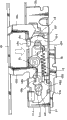
Figure 11 is the disk side panel of expression camera head of the present invention, the perspective view that lid opens and closes mechanism and machinery chassis (mechanical chassis);
Figure 12 is the key-drawing of the state after disk side panel, lid opening and closing mechanism and the machinery chassis of expression camera head of the present invention assembles;
Figure 13 is the perspective view of the motor sub-assembly body of camera head of the present invention;
Figure 14 is the key-drawing of operation that is used to explain the motor sub-assembly body of camera head of the present invention, the state the when cam pin of having represented rotating cam contacts with the first cam projection of swinging operation bar;
Figure 15 is the key-drawing of operation that is used to explain the motor sub-assembly body of camera head of the present invention, the state when the first cam projection of having represented the cam pin of rotating cam and swinging operation bar is thrown off;
Figure 16 is the key-drawing of operation that is used to explain the motor sub-assembly body of camera head of the present invention, the state the when cam pin of having represented rotating cam contacts with the second cam projection of swinging operation bar;
Figure 17 is the key-drawing of operation that is used to explain the motor sub-assembly body of camera head of the present invention, the state the when cam pin of having represented rotating cam contacts with the operation part of slide unit;
Figure 18 is the key-drawing of operation that is used to explain the motor sub-assembly body of camera head of the present invention, the state the when operation part of having represented the cam pin of rotating cam and slide unit is thrown off;
Figure 19 is the key-drawing of operation that is used to explain the motor sub-assembly body of camera head of the present invention, the state the when cam pin of having represented rotating cam contacts with the first cam projection of swinging operation bar;
Figure 20 is used to explain that the lid of camera head of the present invention opens and closes the key-drawing of the operation of mechanism, the state when the pair of locking pawl of having represented Lock Part meshes with a pair of retainer pawl of slide unit;
Figure 21 is used to explain that the lid of camera head of the present invention opens and closes the key-drawing of the operation of mechanism, the state during a pair of retainer pawl disengagement of the pair of locking pawl of having represented Lock Part and slide unit;
Figure 22 is used to explain that the lid of camera head of the present invention opens and closes the key-drawing of the operation of mechanism, has represented the state of pair of locking pawl and slide unit disengagement when the disk lid is opened;
Figure 23 is used to explain that the lid of camera head of the present invention opens and closes the key-drawing of the operation of mechanism, has represented to enter state in the slide unit when disk covers pair of locking pawl when closing;
Figure 24 is the partial sectional view of the major part of camera head of the present invention, has represented that the electronic viewfinder of camera head shrinks by pressure, so that the state when closing the insertion slit of annex piston shoes;
Figure 25 is the partial sectional view of the major part of camera head of the present invention, and the electronic viewfinder of having represented camera head is pulled out so that the state during the insertion slit of the piston shoes that open the attachment;
Figure 26 is the perspective view of the electronic viewfinder of expression camera head of the present invention;
Figure 27 is the perspective view state of expression electronic display unit when being installed on the view finder motion of electronic viewfinder of camera head of the present invention, that see from the plane surface side;
Figure 28 is that the view finder motion of electronic viewfinder of expression camera head of the present invention is at the perspective view when the plane surface side is seen;
Figure 29 is that the view finder motion of electronic viewfinder of camera head is at the perspective view when the basal surface side is seen;
Figure 30 A is the plane graph of view finder motion of the electronic viewfinder of camera head of the present invention;
Figure 30 B is its left side view;
Figure 30 C is its right side view;
Figure 31 A is the upward view of view finder motion of the electronic viewfinder of expression camera head of the present invention;
Figure 31 B is its front view;
Figure 31 C is its rearview;
Figure 32 is that the view finder motion of electronic viewfinder of expression camera head of the present invention is at the decomposition diagram when the plane surface side is seen;
Figure 33 is that the view finder motion of electronic viewfinder of expression camera head of the present invention is at the decomposition diagram when the basal surface side is seen;
Figure 34 is that the view finder motion of electronic viewfinder of expression camera head of the present invention is at the perspective view when the basal surface side is seen;
Figure 35 A and 35B have represented the view finder motion of the electronic viewfinder of device of the present invention respectively, wherein, the upward view of the state that Figure 35 A is expression terminal block lid and pin cap when the view finder motion takes off, and Figure 35 B is the upward view of the state when representing that pin cap is installed on the view finder motion;
Figure 36 A is the plane graph of slider of the electronic viewfinder of camera head of the present invention;
Figure 36 B is its end view;
Figure 36 C is its upward view;
Figure 37 is the perspective view of retainer main body of the electronic viewfinder of expression camera head of the present invention;
Figure 38 is the perspective view of slider main body of the electronic viewfinder of expression camera head of the present invention;
Figure 39 is the perspective view of fittings body of the electronic viewfinder of expression camera head of the present invention;
Figure 40 is the perspective view of flash unit, has represented the particular instance of the annex of camera head of the present invention;
Figure 41 is the key-drawing of the state of expression when the flash unit shown in Figure 40 is installed on the annex piston shoes of camera head of the present invention;
Figure 42 is the key-drawing of the state of electronic viewfinder when state shown in Figure 41 is inclined upwardly about miter angle of expression camera head of the present invention;
Figure 43 is the key-drawing of the state of electronic viewfinder when state shown in Figure 41 is inclined upwardly about an angle of 90 degrees of expression camera head of the present invention;
Embodiment
(embodiment 1)
Introduce the present invention below with reference to the accompanying drawings.
Fig. 1 to 43 has represented the camera head according to the embodiment of the invention.More particularly, Fig. 1 to 4 is respectively perspective view, front view, plane graph and the end view of the camera head of the expression embodiment of the invention; Fig. 5 is the back perspective view of expression camera head, and wherein, its display unit is opened; Fig. 6 is that the expression camera head is at the perspective view when the rear side of disk is seen; Fig. 7 is the front perspective view of expression camera head, and wherein, its disk lid is opened; Fig. 8 is the perspective view of expression camera head, and its disc recording medium is installed on this camera head; Fig. 9 is the end view of camera head of the present invention; Figure 10 is expression when the key-drawing of the state of use when the user grasps camera head during camera head; Figure 11 is the disk side panel of the shell of expression camera head of the present invention, the perspective view that lid opens and closes mechanism and disk drive; Figure 12 is the key-drawing of expression confined state; Figure 13 is the perspective view that the lid of expression camera head of the present invention opens and closes the motor sub-assembly body of mechanism; Figure 14 to 19 is respectively the key-drawing of operation that is used to explain the motor sub-assembly body of camera head of the present invention; Figure 20 to 23 is used to explain that the lid of camera head of the present invention opens and closes the key-drawing of the operation of mechanism.
Figure 24 is the partial sectional view of the major part of expression electronic viewfinder of camera head of the present invention and annex piston shoes; The key-drawing of the state when Figure 25 is the motion of expression electronic viewfinder; Figure 26 is the perspective view of expression electronic viewfinder and view finder motion; Figure 27 is an expression view finder motion at the perspective view when upper surface side is seen, electronic display unit is installed on this view finder motion; Figure 28 is an expression view finder motion at the perspective view when upper surface side is seen; Figure 29 is the view finder motion at the perspective view when the basal surface side is seen; Figure 30 A to 30C is plane graph, left side view and the right side view of view finder motion respectively; Figure 31 A to 31C is respectively upward view, front view and the rearview of view finder motion; Figure 32 is an expression view finder motion at the decomposition diagram when upper surface side is seen; Figure 33 is an expression view finder motion at the decomposition diagram when the basal surface side is seen; The perspective view of the state that Figure 34 is an expression terminal block lid when the view finder motion shown in Figure 29 takes off; And Figure 35 A and 35B are respectively the upward views of view finder motion.
Figure 36 A to 36C is respectively plane graph, end view and the upward view of the slider of view finder motion; Figure 37 is the perspective view of the retainer main body of expression view finder motion; Figure 38 is the perspective view of expression slider main body; Figure 39 is the perspective view of expression fittings body; Figure 40 is the perspective view of flash unit, and this flash unit is as the particular instance of electronic installation; Figure 41 is the key-drawing of the state of expression when the flash unit shown in Figure 40 is installed on the camera head shown in Fig. 1; Figure 42 is the key-drawing of the state of the view finder of the camera head of expression shown in Figure 41 when tilting about miter angle; And the key-drawing of the state during Figure 43 to be the view finder of the camera head of expression shown in Figure 41 tilt about an angle of 90 degrees.
Camera head shown in Fig. 1 to 10 can use the DVD (digital universal disc) of diameter as 8cm, this DVD is as the particular instance of the disc recording medium that is used as information recording carrier, it can be transformed into the signal of telecommunication with optical imagery by CCD (charge coupled device) device for solid photography, so that the signal of telecommunication is recorded on the DVD, perhaps it can make optical imagery be presented at display unit for example on the LCD monitor.Hereinafter, this camera head will be called " magnetic disc type camera head ".But, disc recording medium of the present invention is not limited to DVD, and the present invention can use other CD-R, for example CD-ROM (CD read-only memory).And the disc recording medium of other register system for example magneto optical disk and disk can be used for the present invention.And recording medium is not limited to disc recording medium, uses the cassette tape of banded recording medium, semiconductor recording medium and other various recording mediums of use semiconductor memory to use.
This magnetic disc type camera head 1 comprises: magnetic disk drive apparatus 3 (seeing Fig. 7 to 9), be used to make DVD 2 rotations that are removably mounted on the magnetic disk drive apparatus 3, so that information signal recording (writing) is duplicated (reading) information signal on this DVD 2 and from this DVD 2; The control circuit (not shown) is used to control this magnetic disk drive apparatus 3; Lens devices 4 is used for subject image is introduced CCD as light; Shell 5 is used for holding therein magnetic disk drive apparatus etc.; Disk lid 7, this disk lid 7 is rotatably installed on this shell 5, so that open and close disk separate space part 6; Or the like.
And shell 5 is equipped with annex piston shoes 17 on its top, and annex for example photoflood lamp and external microphone can be removably mounted on these annex piston shoes 17.Annex piston shoes 17 are positioned at the front of electronic viewfinder 16 just, and when electronic viewfinder 16 moved backward, the insertion slit of these annex piston shoes 17 can be opened.Under the state that this insertion slit of annex piston shoes 17 is opened, annex can be installed on these annex piston shoes 17.When be installed on the annex piston shoes 17 at annex after electronic viewfinder 16 being travelled forward, the insertion slit of annex piston shoes 17 is closed, and annex can not be from annex piston shoes 17 separately.When not using annex piston shoes 17, the piston shoes cap 18 of filling the space segment of annex piston shoes 17 as cover is installed on the annex piston shoes 17 usually.Electronic viewfinder 16 and annex piston shoes 17 will be described in detail below.
Remote control light receiving part 20, microphone terminal and stereophony microphone 22 are arranged sequentially on the front surface of front panel 11 with this from top.Remote control light receiving part 20 is receiving units, and this camera head can carry out straighforward operation by it.This remote control light receiving part 20 also can be used as the infrared light radiating portion, is used to launch infrared light, and the focal length of lens devices 4 can be regulated automatically by this infrared light.Although not shown, the microphone terminal comprises video terminal and audio frequency terminal, and these terminals are covered by terminal cap 21, so that can freely open and close.
As illustrated in Figures 5 and 6, the front panel 12 of shell 5 provides battery compartment part 25, and power-supply battery 24 is removably mounted in this battery compartment part 25.Battery compartment part 25 is opened in the rear surface and basal surface of front panel 12, and therefore, power-supply battery 24 can tiltedly below insertion battery compartment the part 25 interior and taking-ups from this battery compartment part 25 from the rear portion.And two supporting metal fittings 26a, 26a are installed on the front panel 12, so that the belt that is used to hang this camera head is installed.In two supporting metal fittings 26a, 26b, a supporting metal fittings 26a is positioned at the right-hand side top of front panel 12, and another supporting metal fittings 26b is positioned at the left-hand side bottom of front panel 12.
Shown in Figure 4 and 5, display unit 28 is installed on the display unit side panel 10 of shell 5, so that can change its attitude.Display unit 28 comprises: flat tabular LCD monitor 29; Panel housing 30 is used for holding therein LCD monitor 29; And panel supporting part 31, be used for so that the mode that the attitude of panel housing 30 can change is bearing in shell 5 with this panel housing 30.
Panel supporting part 31 comprises: horizontally rotate function, so that make panel housing 30 rotate about an angle of 90 degrees degree around the vertical axis along continuous straight runs; And the front and back spinfunction, so that make panel housing 30 rotate about 180 degree angles along fore-and-aft direction around horizontal axis.Therefore, display unit 28 can be arranged to the state that holds shown in Fig. 1 to 4, under this state, panel housing 30 rotatable 90 degree are so that make LCD monitor 29 facing to the back, as shown in Figure 5, under this state, panel housing 30 can be from the state Rotate 180 degree shown in Fig. 5, so that make LCD monitor 29 facing to the front, and this display unit can be arranged in the centre position state suitably.
And.Display unit side panel 10 provides: built-in function part 32, and this built-in function part 32 comprises a plurality of action buttons, these action buttons are covered by panel housing 30, so that can freely open and close; And peripheral operation part 33, this peripheral operation partly comprises a plurality of action buttons that are arranged in panel housing 30 tops.
Shown in Fig. 7 and 8, the disk side panel 8 of shell 5 comprises: side surface portion 8a, and disk lid 7 is installed on this side surface portion 8a; And the periphery edge part, this periphery edge part is continuous with side surface portion 8a, so that around the outward flange of this side surface portion 8a.The peripheral skirt branch of disk side panel 8 comprises along the vertical direction with the continuous upper surface portion 8b of this side surface portion 8a and bottom surface section 8c and along left and right directions and continuous front surface portion 8d and the rear surface part 8e of side surface portion 8a.Disk separate space part 6 is at the front surface portion 8d of side surface portion 8a side opening.Form similar basic semicircle framework from the basic core of the upper surface portion 8b of disk side panel 8 by the part that front surface portion 8d extends to the basic core of bottom surface section 8c.The enhancing part 8f that is used to strengthen is formed at the inboard of basic semicircle frame part, so it can extend internally.
Disk separate space part 6 is formed by the constant zone with opening portion, so that make magnetic disk drive apparatus 3 local exposures.In the present embodiment, to form size be the identical zone of disc recording medium of 8cm with diameter to disk separate space part 6.The platen rotary device 35 of magnetic disk drive apparatus 3 is positioned at the basic central part office of this disk separate space part 6, and diameter is that the DVD 2 (this DVD 2 is expressed as the particular instance of disc recording medium) of 8cm can be installed on the turntable 36 of the central part office that is positioned at platen rotary device 35.Shown in Figure 10 and 11, platen rotary device 35 is fixed on the machinery chassis 37, and these machinery chassis 37 elastic bearings are on the aforementioned separator plate panel.
As shown in Figure 7, the disk separate space part 6 that wherein is furnished with this platen rotary device 35 is covered by disk lid 7, so that can freely open and close, and this disk lid 7 can be rotated to support on the disk side panel 8 at its side surface portion place.The shape of disk lid 7 is identical with the shape of disk separate space part 6, and it comprise covering disk separate space part 6 open side plane surface part 7a and with the continuous periphery surface part 7b of whole substantially periphery of the neighboring of this plane surface part 7a.The periphery surface part 7b of disk lid 7 can pack in the notch part of outer circumferential side of disk separate space part 6 of disk side panel 8.
As shown in Figure 8, disk lid 7 in the present embodiment forms and is similar to shell, wherein, basic 5/6 (about 300 degree) of the periphery of neighboring be circle (this circular portion is about 3/4 just enough greater than the whole periphery of neighboring), and remainder forms and is similar to the rectangle part 7c that comprises straight line.Be equipped with on the rectangle part 7c and cover rotating shaft part 39, this lid rotating shaft part 30 is as pivot, and disk lid 7 can open and close around this pivot.Although not shown, lid rotating shaft part 39 comprises: bolster, this bolster pass rectangle part 7c and extend; And parts of bearings, this parts of bearings has the pair of bearings part, so that the two ends of this bolster of firm support.Parts of bearings is fixed on the disk side panel 8, therefore, and pivotally supporting of disk lid 7.This lid rotating shaft part 39 provides the retainer part, is used to be provided with the maximum open angle (for example 90 degree) of disk lid 7.
This lid rotating shaft part 39 is arranged at the axial direction of bolster be installed on the disk side panel 8 under the state of above-below direction.Therefore, disk lid 7 can be rotated to support on the rear portion of disk side panel 8 by lid rotating shaft part 39.Therefore, under the state of front side, disk lid 7 can be opened about an angle of 90 degrees degree towards horizontal direction at the front surface of magnetic disc type camera head.On the lid rotating shaft part 39 spring members is installed, disk lid 7 any open positions that can be located at still by this spring members in the constant open angle scope, and when disk lid 7 was opened above this open angle, disk lid 7 can be subjected to fexible bias pressure by this spring members.
The core panel 9 that overlaps with this disk side panel 8 comprises: upper surface portion 9a, this upper surface portion 9a insert between the upper surface portion 8b and display unit side panel 10 of disk side panel 8; And front surface portion 9b, this front surface portion 9b continues forward from this upper surface portion 9a, and inserts between front surface portion 8d and the front panel 11.Narrow 42 is set to extend to from the basic core of the upper surface portion 9a of this core panel 9 part of front surface portion 8d bottom, and when this narrow 42 was oblique towards inboard display unit side panel 10 inclinations of conduct, it became concave portions.Have the disk side panel 8 of this narrow 42 and the circular arc shaped portion of core panel 9 and constitute handle portion 43, the user can grasp magnetic disc type camera head 1 by this handle portion 43.
The lid of disk lid 7 opens and closes mechanism 45 and is arranged between core panel 9 and the disk side panel 8.This lid opening and closing mechanism 45 has the disk that will close disk separate space part 6 and covers 7 functions that are locked in the function of closed condition and discharge the lock-out state of this disk lid 7.This lid opens and closes mechanism 45 and will be described in detail below.
Also have, shown in Fig. 3 and 6 etc., hand strap 60 is installed on the disk side panel 8, so that around disk lid 7.These hand strap 60 supportings hand user, that hold handle portion 43 (as the handle portion of shell 5), thus prevent that the user from making magnetic disc type camera head 1 fall unintentionally.
This hand strap 60 comprises: back(-)up belt 61, and this back(-)up belt 61 is fixed on the disk side panel 8 at its each end; And neonychium 62, this neonychium 62 is installed on the back(-)up belt 61, so that contact with the back of the hand of user.One end of back(-)up belt 61 is connected with the installation metal fittings 63 of the preceding side lower part that is fixed on disk side panel 8, and the other end of this back(-)up belt is inserted into inside from the through hole that is formed at disk side panel 8 rear side somewheres, and is fixed on and is installed on the inner installation metal fittings.
Shown in Fig. 6 waited, power knob 64, mode switch rotating disk 65 and record button 66 were positioned at the rear portion of disk side panel 8.Mode switch button 65 is an annular, and power knob 64 is packed in the hole of this circular pattern switching button 65.Power knob 64 comprises and pushes away-push away the type switching device, from the power supply of power-supply battery 24 by pushing power knob 64 on/off.Mode switch rotating disk 65 is used for select operating mode (for example record).When user's rotary mode conversion rotating disk 65, the user can select appropriate mode from " rest image pattern ", " moving image mode " and " monitor/edit pattern ".Also have, record button 66 comprises and pushes away-push away the type switching device, when pushing record button 66, repeatedly begins and finish the shooting of moving image at every turn.
And shutter release button 67 and zoom operation bar 68 are positioned at the back upper lateral part of disk side panel 8.Shutter release button 67 is used to take rest image, and when pressing shutter release button 67, the user can take a rest image at every turn.Also have, zoom operation bar 68 is used for enlarged image when user's shooting or replay image.According to the operational degree of zoom operation bar 68, the user can carry out zoom in stepless mode and amplify in constant scope.
For example, ABS (acrylonitrile one butadiene one styrene) resin is suitable for the material as disk side panel 8, core panel 9, display unit side panel 10, front panel 11 and front panel 12.But, above-mentioned material is not limited to ABS, and other engineering plastics can certainly be used for above-mentioned material.And except that synthetic resin, metal for example aluminium alloy also can be used as above-mentioned material.
The inside of shell 5 along left and right directions (crossing the direction of the optical axial of lens devices 4) separately, therefore, is covered 7 sides at disk and is formed first chamber, and form second chamber in display device side by the aforementioned separator plate panel.The dividing plate panel is made by plate-shaped member, and it fixedly secures inside at shell 5 by hold-down screw.Although for example stainless steel (SUS) is suitable for the material as the dividing plate panel, steel, aluminium alloy and other metal also can be as the materials of dividing plate panel.And except that metal, engineering plastics also can be used as the material of dividing plate panel.
Although not shown, magnetic disk drive apparatus 3 is contained in first chamber of shell 5, and lens devices 4, control circuit part etc. are contained in second chamber.Therefore, the tangible a plurality of supporting convex that are formed in its face side of dividing plate panel are so that supporting magnetic disk drive apparatus 3.Also have, the tangible a plurality of supporting members that are formed in its another face side of dividing plate panel are so that supporting lens device 4, printed circuit board (PCB) etc.Control circuit partly comprises microcomputer, storage device (RAM (random access memory), ROM (read-only memory)), capacitor, resistor and other electronic unit, printed circuit board (PCB) etc., and these electronic units are installed on this printed circuit board (PCB).
Shown in Figure 11 and 12 etc., magnetic disk drive apparatus 3 comprises: machinery chassis 37, and this machinery chassis 37 is installed on the dividing plate panel; Platen rotary device 35, this platen rotary device 35 are fixed on this machinery chassis 37; Optical pickup device 71, this optical pickup device 71 have been represented a particular instance of pickup device; Or the like.Machinery chassis 37 is made by the conductive plate material, it by a plurality of installation insulators 14 elastic bearing on the dividing plate panel, the elastomeric element that this installation insulator 14 is made by insulating material and forming.
The machinery chassis 37 that is installed on the dividing plate panel by these installation insulators 14 comprises the frame-like parts with enough hard intensities.Conductor part between machinery chassis 37 and dividing plate panel is connected to each other by unshowned grounded parts, and like this, it can be at an easy rate with outwards discharges such as static.Be installed in platen rotary device 35 on this machinery chassis 37 and comprise turntable 36 on the rotating part that is fixed on the Spindle Motor 72 on this machinery chassis 37 and is fixed on this Spindle Motor 72.
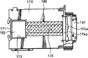
Also have, optical pickup device 71 comprises: twin shaft actuator 74, this twin shaft actuator 74 comprise the imaging lens system 74a facing to the information recording surface of DVD 2; Slide unit 75, twin shaft actuator 74 are installed on this slide unit 75; Or the like.Slide unit 75 can guide and moves by unshowned two leading axles.It is parallel to each other that two leading axles are arranged to cross Spindle Motor 72, and shooting telecontrol equipment 76 is arranged near the leading axle.
Although not shown, shooting telecontrol equipment 76 comprises: feed screw axle, this feed screw axle and the feed screw nut engagement that is installed on the slide unit 75; And the feeding motor, this feeding motor uses the rotating shaft of this feed screw axle as it.The feed screw axle is arranged to be parallel to the leading axle of optical pickup device 71, and it pivotally is bearing on the machinery chassis 37.Therefore, when the feed screw axle rotated by driving the feeding motor, optical pickup device 71 was according to the direction of rotation of feed screw axle and selectively along moving near the direction of turntable 36 or the direction of leaving turntable 36.Machinery chassis 37, platen rotary device 35, optical pickup device 71, shooting telecontrol equipment 76 and other associated mechanisms constitute magnetic disk drive apparatus 3.
The dividing plate panel is fixed on the precalculated position in the shell 5, magnetic disk drive apparatus with said structure is installed on this dividing plate panel, therefore, turntable of platen rotary device 35 36 and its peripheral part be suitable is positioned on the disk separate space part 6 of disk side panel 8, as shown in Figure 7.This disk separate space part 6 opens and closes by disk lid 7, and this disk lid 7 opens and closes mechanism 45 by lid and locks and unblank.
Shown in Fig. 7,10 and 11 etc., lid opens and closes mechanism 45 and comprises: Lock Part 46, this Lock Part 46 are fixed on the disk lid 7; Functional unit 47, this functional unit 47 is slidably mounted on the base plate 51, and this base plate 51 is as parts of disk side panel 8; Slide unit 48 and rotary manipulation bar 49; Motor sub-assembly body 50 is used to make slide unit 49 to seesaw; Base plate 51 is used to support rotary manipulation bar 49 and motor sub-assembly body 50; Or the like.
Shown in Figure 20 to 23, slide unit 48 is bearing on the front surface portion 51a of base plate 51 slidably, and rotary manipulation bar 49 also can be rotated to support on the front surface portion 51a of base plate 51.Slide unit 48 has a pair of retainer pawl 48a, 48b, this to retainer pawl 48a, 48b can be with the pair of locking pawl 46a of Lock Part 46,46b meshes and throw off.A pair of retainer pawl 48a, 48b form along equidirectional from slide unit 48 tabular base part and raise, and a pair of guiding groove 48c, the 48c that extend along the glide direction of slide unit 48 are arranged on the base part of retainer pawl 48a, 48b.
Being fixed on a pair of directing pin 54a, 54a on the front surface portion 51a and a pair of guiding groove 48c, the 48c of slide unit 48 slidably mates.A pair of directing pin 54a, 54b support slide unit 48, and like this, slide unit 48 can be along the glide direction preset distance that moves up and down.Also have, rotary manipulation bar 49 can be rotated to support on the basic core of base part of slide unit 48 by being fixed on rotating shaft 55 on the front surface portion 51a.Rotating shaft 55 passes the Long Circle hole of slide unit 48 and extends, thereby can prevent to hinder the motion of slide unit 48.
Therefore, before disk lid 7 was closed, a pair of retainer pawl 48a, the 48b that have moved to the slide unit 48 of position, top side faced toward pair of locking pawl 46a, the 46b of Lock Part 46 just.When Lock Part 46 from this state towards base plate during 51 lateral movements, the inclined surface of pair of locking pawl 46a, 46b part promotes the upper part of a pair of retainer pawl 48a, 48b downwards.This thrust make slide unit 48 against the spring force of coil spring 56 to lower slider, so that make each lock pawl 46a, 46b can pass through respective stop device pawl 48a, 48b.Therefore, corresponding lock pawl 46a, 46b and retainer pawl 48a, 48b are engaged with each other, thereby make Lock Part 46 and slide unit 48 lockings.This state as shown in figure 20.
In order to remain on the engagement between pair of locking pawl 46a, 46b and a pair of retainer pawl 48a, the 48b, as shown in Figs. 7-9, a pair of patchhole 57a, 57b are formed on the front surface portion 8d of disk side panel 8, and pair of locking pawl 46a, 46b insert this among patchhole 57a, the 57b.Therefore, when disk lid 7 opened and closed, lock pawl 46a, 46b inserted these patchholes 57a, 57b neutralization and eject from these patchholes 57a, 57b.
When opening and closing mechanism 45, lid becomes the state shown in Figure 21 from the state-transition shown in Figure 20, so that make this coil spring 56 elongations against the spring force of coil spring 56, thereby when slide unit 48 was moved in downward direction, a pair of retainer pawl 48a, 48b and pair of locking pawl 46a, 46b threw off.Therefore, be released in the lock-out state between pair of locking pawl 46a, 46b and a pair of retainer pawl 48a, the 48b, thereby can open disk lid 7.Therefore, the user holds part disk lid 7, close Lock Part 46, so that make disk lid 7 to inner rotary, thereby makes the lid rotating shaft part 39 side direction sidepiece rotation in the past of disk lid 7 around the rear portion.Therefore, disk lid 7 is to front opening, so that expose disk separate space part 6.
Then, when disk lid 7 was closed once more, as shown in figure 22, disk lid 7 will be near shell 5.Then, when pair of locking pawl 46a, 46b by a pair of patchhole 57a, 57b and during near slide unit 48, a lock pawl 46b contacts with the importation 49a of relative rotary manipulation bar 49.At this moment, when lock pawl 46a, 46b further promoted against the spring force of coil spring 56, importation 49a and stop dog part 48e threw off, so discharge slide unit 48.This state is a state as shown in figure 23.At this moment, slide unit 48 moves upward under the spring force effect of coil spring 56, thereby pair of locking pawl 46a, 46b and a pair of retainer pawl 48a, 48b are thrown off.Therefore, Lock Part 46 returns the lock-out state shown in Figure 20.
Therefore, slide unit 48 in the spring force effect lower edge of spring members 56 forwards to motion, thereby make a pair of retainer pawl 48a, 48b and pair of locking pawl 46a, 46b engagement.Therefore, Lock Part 46 and slide unit 48 are by meshing in the engagement of (they respectively form a pair of) between lock pawl 46a and the retainer pawl 48a and between lock pawl 46b and retainer pawl 48b.
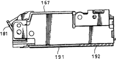
Lid opens and closes the opening operation of mechanism 45 and carries out by the motor sub-assembly body 50 that is installed in equally on the base plate 51.The structure of this motor sub-assembly body 50 is shown in Figure 13 and Figure 14 to 19.More particularly, motor sub-assembly body 50 comprises: CD-ROM drive motor 80; Motor shell 81 is used for holding drive 80 therein; Rotating cam 82, this rotating cam 82 is rotatably installed on the motor shell 81; Swinging operation bar 83, this swinging operation bar 83 is swung by the rotation of rotating cam 82; Or the like.
Shown in Figure 14 to 19, rotating cam 82 provides cam pin 84 on its upper surface, so that make swinging operation bar 83 swing, this cam pin 84 also makes slide unit 48 move along fore-and-aft direction.Cam pin 84 is around the rotating shaft 82a rotation of rotating cam 82, and the operation part 48f of the operation part 83a of swinging operation bar 83 and slide unit 48 is positioned on the track of cam pin 84 rotations.
Swinging operation bar 83 is by pivot 85 supportings of standing on the motor shell 81, and like this, it can freely swing on the surface of motor shell 81 along in-plane.This swinging operation bar 83 provides forked operation part 83a at its end.The operation part 83a of swinging operation bar 83 comprises the first cam lobe 86a and the second cam lobe 86b on the two end portions that is formed at swinging operation bar 83.Swinging operation bar 83 can be by being swung around pivot 85 by the power of the first and second cam lobe 86a, 86b input.
Swinging operation bar 82 it, the end relative with operation part 83a provide: operation part 86c, be used to the excitation that encourages sense switch 87/ to eliminate to sense switch, thereby the operation of controlling and driving motor 80; And spring receiving-member 86d, be used for fixing an end of torsionspring 88.The motion of torsionspring 88 control swinging operation bars 83, and the other end of this torsionspring 88 is fixed on the cover 89.Cover 89 is used to cover the mid portion of swinging operation bar 83, falls so that prevent swinging operation bar 83, thereby can keep the stable oscillation of swinging operation bar 83.Cover 89 is fixed on the motor shell 81.Under sense switch 87 was installed on state on the flexible connection board 90, sense switch 87 was mounted to the operation part 86c facing to swinging operation bar 83.According to the swing state of this swinging operation bar 83, the operation part 87a of sense switch 87 is energized and de-energisation, thus the driving of controlling and driving motor 80.
The operation part 48f of slide unit 48 forms in a side opposite with the side that a pair of retainer pawl 48a, 48b are installed and protrudes along relative direction.When the cam pin 84 of rotating cam 82 promoted the operation part 48f of slide unit 48, slide unit 48 can slide along the above-below direction of arranging a pair of retainer pawl 48a, 48b.
In having the motor sub-assembly body 50 of said structure, the slide of slide unit 48 is for example following to carry out.Figure 14 to 19 is the views that are used to explain the operation of motor sub-assembly body 50.Figure 14 is the common initial condition of expression.In this initial condition, the cam pin 84 of rotating cam 82 contacts with the first cam lobe 86a of swinging operation bar 83.Like this, swinging operation bar 83 is arranged on the position when swinging operation bar 83 is swung maximum along clockwise direction around oscillation center.Therefore, operation part 86c promotes functional unit 87a, so that excitation sense switch 87.Also have, slide unit 48 is positioned at the upper position when its most close motor sub-assembly body 50, and its operation part 48f is positioned on the rotational trajectory of cam pin 84.Therefore, lid opens and closes arrangement of mechanism and becomes lock-out state, and under this state, it locks Lock Part 46, perhaps is arranged to basic similarly state.
When make functional unit 47 user under the state shown in Figure 14 along opening direction (from the front side of shell 5 to the direction of rear side) when sliding, the aforesaid operations of functional unit 47 is detected by sense switch 87, and supplies with CD-ROM drive motor 80 according to the control signal from the detection signal of this sense switch 87.Therefore, CD-ROM drive motor 80 begins to drive, so that rotating cam 82 is rotated in a clockwise direction, so cam pin 84 and first cam lobe 86a disengagement.Therefore, although rotating cam 82 becomes the state shown in Figure 15 from the state shown in Figure 14, swinging operation bar 83 also keeps initial condition under the spring force effect of torsionspring 88, thereby can keep the energized condition of sense switch 87, also keeps the lock-out state of slide unit 48.
And, when rotating cam 82 is rotated in a clockwise direction, and cam pin 84 contacts and when promoting the second cam lobe 86b, as shown in figure 16, swinging operation bar 83 is swung around pivot 85 in the counterclockwise direction against the spring force of torsionspring 88.Therefore, the operation part 86c of swinging operation bar 83 and operation part 87a throw off, and sense switch 87 becomes de-energized state from energized condition.When sense switch 87 when energized condition becomes de-energized state, the driving of CD-ROM drive motor 80 does not stop, CD-ROM drive motor 80 can continue rotation.And slide unit 48 can keep lock-out state, contacts with operation part 48f up to cam pin 84.
Then, when rotating cam 82 when the state shown in Figure 16 becomes state shown in Figure 17, because cam pin 84 promotes operation part 48f, so slide unit 48 slides along downward direction (along making slide unit 48 leave the direction of motor sub-assembly body 50) against the spring force of coil spring 56.Therefore, as mentioned above, Lock Part 46 discharges from locking by slide unit 48, and disk lid 7 can be opened.At this moment, can under the effect of torsionspring 88, keep making swinging operation bar 83 to swing maximum state in the counterclockwise direction.
Subsequently, when rotating cam 82 when state shown in Figure 17 becomes state shown in Figure 18, although cam pin 84 separates with functional unit 48f, but because therefore the importation 49a of the stop dog part 48e of slide unit 48 and rotary manipulation bar 49 engagement can keep making slide unit 48 to be positioned at the state of lower end.Also have the swinging operation bar 48 same maximum states of swing in the counterclockwise direction that under the spring force effect of torsionspring 88, keep.
Then, when rotating cam 82 when the state shown in Figure 18 becomes state shown in Figure 19, cam pin 84 contacts with the first cam lobe 86a of swinging operation bar 83, so that outwards promote the first cam lobe 86a, like this, swinging operation bar 83 is swung around pivot 85 along clockwise direction against the spring force of torsionspring 88.Therefore, the operation part 86c of swinging operation bar 83 contacts with the functional unit 87a of sense switch 87, so that promote functional unit 87a, thereby makes sense switch 87 convert ON to from OFF.According to the switching signal that when sense switch 87 is transformed into ON, obtains, stop power supply, and when CD-ROM drive motor 80 stopped, rotating cam 82 stopped the rotation to CD-ROM drive motor 80.
Then, rotating cam 82 returns the state shown in Figure 14 from the state shown in Figure 19, and repeats the aforementioned operation shown in Figure 14 to 19.
According to the magnetic disc type camera head 1 with said structure, disk lid 7 for example can open and close as follows.At first, the power knob 64 of magnetic disc type camera head 1 forces down so that make 1 energising of magnetic disc type camera head.
When magnetic disc type camera head 1 at this moment is in disk and covers 7 closing state, shown in Fig. 1 to 4, pair of locking pawl 46a, the 46b that is fixed on the Lock Part 46 on the disk lid 7 passes and is formed at a pair of patchhole 57a, the 57b on the disk side panel 8 and enters in the shell 5, and open and close a pair of retainer pawl 48a, 48b engagement on the slide unit 48 of mechanism 45, thereby lock with lid.Figure 14 and 20 has represented that lid opens and closes mechanism 45 state at this moment.Under this state, because the state that keeps Lock Part 52 to lock by slide unit 48, so the user can not open disk lid 7.
Cover under 7 closing state at disk, when the functional unit 47 of user's arrangements of operations on the handle portion 43 of shell 5, the opening operation of beginning disk lid 7.At first, when the user made functional unit 47 open the backward directions slip of direction along conduct, the opening operation of disk lid 7 detected by being arranged near functional unit 47 sense switches 44.According to the signal that detects by this sense switch 44, the CD-ROM drive motor 80 of beginning CD-ROM drive motor assembly body 50.Then, when driving CD-ROM drive motor 80, when rotating cam 82 when the state shown in Figure 15 becomes state shown in Figure 17 by the state shown in Figure 16, the cam pin 84 of rotating cam 82 contacts with the operation part 48f that is formed at slide unit 48 tops, and pushes this operation part 48f.
When operation part 48 was promoted by cam pin 84, as mentioned above, slide unit 48 slided along the direction of leaving rotating cam 82 downward direction of magnetic disc type camera head 1 (in the present embodiment along).When slide unit 48 slided, a pair of retainer pawl 48a, 48b and pair of locking pawl 46a, 46b threw off, thereby discharged the state when Lock Part 46 is locked by slide unit 48.Figure 17 and 21 has represented these locking release condition of Lock Part 46.
Because Lock Part 46 is arranged to release condition, therefore, disk lid 7 is opened a little being arranged under the effect of cover spring force of opening near spring (not shown) (this open spring can be arranged in cover the rotating shaft part 39) on the rotating shaft part 39 (this lid rotating shaft partly is that disk covers 7 pivot).Figure 22 has represented the open mode of this disk lid 7.Therefore, the user can strike out disk lid 7 with the hand.Therefore, as shown in Figs. 7-9 when the user outwards opens disk and covers 7 with hand, disk lid 7 can be opened.Therefore, can expose the DVD 2 that is positioned on the turntable 36 (this turntable 36 is positioned at the basic central part office of disk separate space part 6), take out DVD 2 thereby the user can be loaded in DVD 2 on the turntable 36 or from this turntable 36 at an easy rate.
When opening this disk and cover 7, though disk lid 7 around it the rear portion in the past the side direction sidepiece open, hand strap 60 also can be avoided along downward direction.Therefore, can prevent that hand strap 60 from disturbing the opening operation of disk lid 7, and disk lid 7 can smoothly be opened.In addition, compare with the camera head that the disk lid is opened from upside along downward direction, the open angle of disk lid 7 can increase (the opening and closing angle of disk lid 7 can be arranged to greater than 90 degree).Therefore, can prevent that disk lid 7 from disturbing the replacing of disk, and therefore make the user can change disk at an easy rate.
When disk lid 7 was closed from covering 7 open modes as the disk shown in Fig. 8 waits, disk lid 7 made disk separate space part 6 close near disk side panel 8 then.At this moment, being fixed on pair of locking pawl 46a, the 46b that disk covers the Lock Part 46 of 7 inboards enters among a pair of patchhole 57a, the 57b of disk side panel 8, so that pass through the importation 49a that pressure promotes rotary manipulation bar 49, thereby the importation 49a of rotary manipulation bar 49 is rotated backward.Therefore, as shown in figure 23, because the stop dog part 48e of the importation 49a of rotary manipulation bar 49 and slide unit 48 throws off, therefore, slide unit 48 slides to motor sub-assembly body 50 sides under the spring force effect of coil spring 56.
Therefore, pair of locking pawl 46a, the 46b of a pair of retainer pawl 48a, the 48b of slide unit 48 and Lock Part 46 engagement.Therefore, Lock Part 46 keeps with slide unit 48 engagements and by this slide unit 48, thereby closes disk lid 7 under the state that lid opening and closing mechanism 45 locks.Figure 14 and 20 has represented that the disk lid opens and closes this lock-out state of mechanism 45.
Also have, shown in Figure 24 to 26, electronic viewfinder 16 is installed on the magnetic disc type camera head 1 by view finder motion 160.The view finder motion is useful on function and the tilt function that slides along the fore-and-aft direction of magnetic disc type camera head 1, and like this, its rear portion can rotate along the vertical direction around fore-end.Therefore, electronic viewfinder 16 can move in preset range along the fore-and-aft direction of magnetic disc type camera head 1, and it can also rotate predetermined angular along fore-and-aft direction in any position that it moves to.In this tilt function in the present embodiment, this view finder motion 160 can rotate between the horizontal level of the optical axial that is parallel to lens devices 4 and upright position, in this upright position, it from horizontal level along upward to the rotation about an angle of 90 degrees degree.
The structure of view finder motion 160 is shown in Figure 27 to 39.More particularly, view finder motion 160 comprises: retainer 166, and this retainer 166 has the U-shaped cross section; Slider 167 and sliding panel 168, this slider 167 and sliding panel 168 remain in the concave portions of this retainer 166 slidably; Barricade 169, this barricade 169 is fixed on the slider 167; Or the like.
Shown in Figure 32,33 etc., retainer 166 comprises retainer main body 170 and the inner fixing body 171 with U-shaped cross section, and inner fixing body 171 is installed in the U-shaped concave portions of retainer main body 170.More particularly, as shown in figure 37, retainer main body 170 comprises: rectangular base surface portion 170a; And side surface portion 170b, 170c, the both side surface of the Width of this side surface portion 170b, 170c and this basal surface part 170a is continuously so that raise.Guiding Long Circle hole 172 is formed at the basic core of basal surface part 170a, and continuous along the longitudinal direction.
And square notch part 173 is formed at that basal surface part 170a goes up and at its longitudinal direction one end, and the flexible connection board that is connected with electronic display unit 164 inserts in this notch part 173.The positioning step shape part 174a that is used for the inner fixing body 171 of appropriate location is formed at that basal surface part 170a goes up and at its longitudinal direction other end.Also have, be used for supporting part 174b, the 174c of retainer 166 firm support on shell 5 is arranged in side surface portion 170b, 170c.Reference number 174d, 174e shown in Figure 32 represents to support the supporting part of unshowned bridging board.
Equally, inner fixing body 171 comprises basal surface part 171a and left side and right lateral surface part 171b, 171c.Be arranged on the basal surface part 171a of inner fixing body 171 with the localization part 175a of positioning step shape part 174a engagement and with the turning frame part 175b of notch part 173 engagements.And a pair of slit 176 is arranged on the two side portions of basal surface part 171a by this way, promptly this in the end of notch part 173 sides, and the other end extends near the end of localization part 175a side to an end opening of slit 176.Banded basal surface part 171a is formed with a pair of slit 176 in inner fixing body 171.At this moment, the working hole 171d that is used for by riveted joint fixed guide pin 186 (back will be introduced) is arranged in the front portion of the turning frame part 175b of basal surface part 171a.
Shown in Figure 32 waited, guide rail 177 was formed on the inner surface of the left side of inner fixing body 171 and right lateral surface part 171b, 171c, thus, will slide so that extension along the longitudinal direction.Guiding groove 178 engagements on guide rail 177 and the both side surface that is formed at sliding panel 168 thus, are bearing on the inner fixing body 171 sliding panel 168 so that can slide along the longitudinal direction.Sliding panel 168 can slide in preset range along the longitudinal direction along with the moving through barricade 169 of slider 167.At this moment, the mate 168a that is used for the motion of limit slippage plate 168 protrudes on the upper surface of sliding panel 168.
Shown in Figure 32,33 etc., slider 167 comprises the slider main body 180 with U-shaped cross section, the fittings body 181 with U-shaped like cross section and barricade 169.As shown in figure 38, slider main body 180 comprises basal surface part 180a and side surface portion 180b, 180c, and the two side portions of this side surface portion 180b, 180c and this basal surface part 180a is continuous; And square notch part 180d is formed on the basal surface part 180a, the turning frame part 175 of inner fixing body 171 and this square notch part 180d engagement.Be used to make the slider 167 level and smooth slides 187 that slide to be installed in the basal surface of the two side portions of basal surface part 180a respectively.
Also have, left side and right lateral surface part 180b, 180c provide support unit 180a, and this support unit 180a protrudes at the opposite side of basal surface part 180a.Each supporting part 180e has lock part 182b, 182c, the 182d that is arranged in three positions, so that at precalculated position locking support holes 182a and fittings body 181.And each support unit 180e provides retainer part 182e, so that the rotation amount of limiting joint body 181.
Shown in figure 32, aforementioned sliding panel 169 cross slider main body 180 and be arranged to be closed in the left side and right lateral surface part 180b, 180c between opening portion, thereby they are fixed into one.The two end portions of barricade 169 is arranged to the outside facing to respective side surface part 180b, 180c, and forms leaf spring 169a.The inner surface of the inner fixing body 171 of leaf spring 169a backup is so that produce the resistance of suitable size.
Through hole 180f is formed at the basic central part office of the basal surface part 180a of slider main body 180.One end of directing pin 186 passes this through hole 180f.The other end of directing pin 186 passes the Long Circle bullport 172 of retainer main body 170, and the two ends of directing pin 186 stretch by riveted joint, so slider main body 180 is slidably mounted on the retainer main body 170.At this moment, when slider main body 180 was inserted the downside of basal surface part of basal surface part 180a of inner fixing body 171, the basal surface part 180a of slider main body 180 can be made for and be not obvious.This can pass that a pair of slit 176,176 on the basal surface part 180a that is arranged in inner fixing body 171 extends at both side surface part 180b, the 180c of slider main body 180 and realize when protruding upward.
Figure 32 and 33 reference number 188 have represented to be used to protect the pin cap of directing pin 186.Effusion groove 188a has the effusion groove 188a on the inner surface that is formed at it, contacts with the head of directing pin 186 to avoid it.This pin cap 188 by fixture for example bonding agent be fixed on the basal surface of retainer main body 170.Also have, reference number 191 expression flexible connection board lids are used to protect flexible connection board 190.This flexible connection board lid 191 is fixed on the basal surface of retainer main body 170 by pad 192, this pad 192 by fixture for example bonding agent be fixed on the bottom of this retainer main body 170.Pad is formed by the abrasive paper with suitable thickness, so that protection flexible connection board 190.
Although metal for example stainless steel and steel can be used as the suitable material of retainer main body 170, slider main body 180, fittings body 181 and barricade 169, the present invention is not limited thereto, and the engineering plastics with proper strength and rigidity also can use.Also have, although for example ABS (acrylonitrile-butadiene-styrene (ABS)) resin and other engineering plastics can be used as the suitable material of inner fixing body 171, sliding panel 168, pin cap 188 and flexible connection board lid 191, but the present invention is not limited thereto, and metal for example stainless steel and steel also can use.By compression (contracting) for example polyester (PET (polyethylene terephthalate), PBT (polybutylene terephthalate ester (polybutadiene terephthalate)) plate and Merlon (PC) plate can reduce the cost and the number of processing.Particularly,, do not use molded resin material, but polyester sheet and polycarbonate plate can gain in strength, and reduce thickness by compressing these plates for pin cap 188 and flexible connection board lid.
Then, slider 167 is assemblied on the retainer main body 170.At this moment, the basal surface part 180a of slider main body 180 inserts in the basal surface bottom partly of inner fixing body 171, and a pair of side surface portion 180b, 180c pack in a pair of slit 176,176 on the basal surface part that is formed at inner fixing body 171, then, directing pin 186 is inserted from the working hole 171d of basal surface part 171a, and fixes by riveted joint.Therefore, shown in Figure 35 A, slider 167 is connected with retainer main body 170 by directing pin 186, so that can be free to slide.And shown in Figure 35 B, pin cap 188 is fixed on the basal surface of retainer main body 170, so that the head of hide boot pin 186.Therefore, shown in Figure 28, Figure 30 A to 30C and Figure 31 A to 31C, assembled view finder motion 160.
And as shown in figure 29, the head portion of flexible connection board 190 laterally protrudes from the mid portion of flexible connection board lid.Therefore, even mobile a little,, therefore can prevent that stress is applied to the connector insertion position because the head portion of flexible connection board 190 can move when the connector insertion position.In addition, because the head portion of flexible connection board 190 is clipped between pin cap 188 and the flexible connection board lid 191, and it can move in constant clearance, therefore can prevent that flexible connection board 190 from being blocked by other assembly, and can also prevent that it from being rubbed and damage.
The structure of annex piston shoes 17 as shown in figure 24, the insertion slit 230 of these annex piston shoes 17 opens and closes by view finder motion 160.Just, annex piston shoes 17 comprise: piston shoes main body 231, and this piston shoes main body 231 is formed by the single metal plate member; And connector component 232, this connector component 232 is integral the inside that is installed in piston shoes main body 231.
Piston shoes main body 231 comprises: basal surface part 231a, and this basal surface part 231a forms square shape; A pair of side surface portion 231b, these both sides to side surface portion 231b and this basal surface part 231a are continuous; A pair of upper surface portion 231c, this is continuous to upper surface portion 231c and respective side surface 231b; And retainer part 231d, insertion slit 230 sides of this retainer part 231d and each upper surface portion 231c are continuous.Side surface portion 231b forms by the crooked an angle of 90 degrees degree of top along continuous straight runs that makes this side surface portion 231b.Then, the end of insertion slit 230 sides of retainer part 231d by making upper surface portion 231c forms along the crooked proper angle of downward direction (for example 15 to 45 degree).
Also have, connector component 232 comprises: block connector body 233; A plurality of bonder terminals, these bonder terminals are packed in this connector body 233; And slide lid 235, this slide lid 235 is used to open and close a plurality of bonder terminals; Or the like.Flexible connection board 237 is connected with bonder terminal 234, and bonder terminal 234 by flexible connection board 237 and with power supply for example power-supply battery 24 be connected.Therefore, the annex for example foot part of flash unit insert to insert in the slit 130, and slide lid opened by this foot part, so that splicing ear can contact with bonder terminal 234, thereby can power to the annex that is installed on the annex piston shoes 17.
Figure 40 has represented flash unit 240, and this flash unit 240 has been represented the particular instance of aforementioned annex.This flash unit 240 comprises foot part, this foot part and 17 engagements of annex piston shoes.This foot part 241 provides electric contact, and comprises terminal 242, and this terminal 242 contacts with electric contact, so that can be electrically connected with flash unit 240.Flash unit 240 is merely able to insert in the annex piston shoes 17 along predetermined direction, and receiving-member 243 is fixed on this foot part 241.The main part 244 of flash unit 240 can be rotated to support on the receiving-member 243.Flash unit 240 comprises rotating mechanism 245, detent mechanism is arranged between receiving-member 243 and the main part 244, the rotation of main part 244 can temporarily stop at the precalculated position by this detent mechanism, and when main part 244 when the precalculated position Rotate 180 is spent, can stop the rotation of main part 244.
And flash unit 240 comprises locking mechanism, is used to lock the position of foot part 241 with respect to annex piston shoes 17.This latch mechanism comprises pressing device parts and functional component.The spirality cam path is formed on one of them parts, and the mesh bulge that meshes with this cam path is formed on another parts.Functional component is moved along predetermined direction, thereby makes the pressing device component movement, so that the position of locking foot part 241.The pressing device parts of Lock Part provide contact component, and this contact component has big frictional force.When contact component contacted with annex piston shoes 17, foot part 241 can lock by the frictional force between this contact component and annex piston shoes 17.Synthetic resin is suitable for use as the material of contact component.
Therefore, power to flash unit 240 by terminal 242 from bonder terminal 234.Therefore, the user can come photographic images by the magnetic disc type camera head 1 that uses flash unit 240.At this moment, the upper surface portion 231c of annex piston shoes 17 is kept by rotating mechanism 245, and therefore fixedly secures.Therefore, can prevent that standing part owing to flash unit 240 from getting loose makes flash unit 240 accidental falls.In state shown in Figure 41, at this moment magnetic disc type camera head 1 is in this state.
Also have, because view finder motion 160 has the tilt function that is independent of aforementioned sliding function, therefore, the electronic viewfinder 16 of magnetic disc type camera head 1 can make its eyepiece part 16a be inclined upwardly.Figure 42 represented when electronic viewfinder 16 along the state when tilting about miter angle upward.And, Figure 43 represented when electronic viewfinder 16 along the state when tilting about an angle of 90 degrees upward, like this, the user can watch eyepiece part 16a from basic vertical direction.The visual angle of electronic viewfinder 16 can change, thereby can make the user come photographic images with various postures.
As previously mentioned, for the disk lid 7 magnetic disc type camera heads 1 that can open and close, the user can keep state shown in Figure 10 and shot object by make magnetic disc type camera head 1 with hand.At this moment, the part of the disk side panel 8 of shell 5 and disk lid 7 forms handle portion, and the user can hold magnetic disc type camera head 1 by this handle portion.In addition because whole substantially this handle portion is for circular substantially, therefore, the user can be by big handle portion shot object stably.
Also have, because narrow 42 is arranged on the inboard of handle portion 43, therefore, the user can keep this narrow 42 with forefinger to the finger tip of little finger of toe, thereby can produce enough big grip.And, because packing into, lid opening and closing mechanism 45 in the handle portion 43 volume inside zones, therefore can efficiently utilize the area of space in the shell 5.Therefore, can make shell 5 miniaturizations by eliminating clear areas in the shell 5.Therefore, can make whole equipment miniaturization.
And, shown in Fig. 3 and 4 etc., because protrude forward from the front portion of lens devices 4 front portion of handle portion 43, therefore, although the size of the disk side of magnetic disc type camera head 1 be made for and the consistent size that is complementary of the standard of recording medium, and think the standard of recording medium as used herein, but the size of lens devices side can reduce as much as possible, whole device can miniaturization.Particularly, when diameter is DVD, the CD-ROM of 8cm and other disc recording medium when being used for recording medium, as shown in figure 10, the size of whole magnetic disk formula camera head 1 can be set to the size suitable with the specification of palm camera head.More particularly, according to the present invention, the camera part is less than handle portion, and whole magnetic disk formula camera head 1 can miniaturization.Therefore, magnetic disc type camera head 1 of the present invention is applicable to and uses the camera head purposes of minidisk as recording medium.
Previous embodiment shown in the present invention is not limited in the accompanying drawings can be carried out various variations under the situation that does not break away from main points of the present invention.For example, although the present invention is used to use the magnetic disc type camera head of DVD as recording medium, the present invention is not limited thereto, also can be used for the disc recording medium of other register system, for example magneto optical disk and disk.At this moment, according to the kind of recording medium, the camera head that is used for above-mentioned magneto optical disk and disk can be magneto-optic camera head, magnetic camera head etc.
The preferred embodiments of the present invention have been introduced with reference to the accompanying drawings, but should know, the present invention is not limited thereto, and under the situation that does not break away from the spirit or scope of the present invention of being determined by accessory claim, those skilled in the art can carry out various variations and change.
Claims (17)
1. camera head comprises:
Platen rotary device is used to make the turntable rotation, and disc recording medium is removably mounted on this turntable with erectility;
Pickup device, this pickup device can with the information signal recording of the corresponding image of importing by at least one lens devices of object light on the described disc recording medium that rotates by described platen rotary device;
Shell, this shell comprise disk separate space part, are used for holding therein described platen rotary device and described pickup device, and described turntable is arranged in this disk separate space part;
The disk lid, this disk lid is installed on the described shell, so that can freely open and close, thereby covers described disk separate space part;
It is characterized in that, make described disk lid, by forming the handle portion that is formed for keeping described camera head from the sunk part on front portion to the top of the described disk separate space part of described shell, this sunk part and described disk lid overlapping with hand for slightly circular;
The edge, front portion of the described disk separate space part of described shell is forwards to protruding from described lens devices.
2. camera head according to claim 1, wherein: basic 3/4 part of the periphery of described disk lid is circular, and remaining about 1/4 part of this disk lid by a rotating shaft part rotatably support in the rear portion, side of described shell, and described disk lid can be middle mind-set side opening with rotating shaft, thereby opens the disk lid forwardly.
3. camera head according to claim 1, wherein: the size of described disk lid and diameter are that the described disc recording medium of 8cm is corresponding.
4. camera head according to claim 1, wherein: described disk is stamped the hand strap of the outside that is arranged in it, described hand strap is lax, thereby described disk lid can be opened along horizontal direction, one end of described hand strap is fixed on the preceding side lower part of described shell, and the other end of described hand strap is fixed on a certain position of described shell rear side.
5. camera head according to claim 4, wherein, described hand strap comprises: back(-)up belt, the two ends of this back(-)up belt are fixed on the described shell; And neonychium; this neonychium is installed on the described back(-)up belt; one end of described back(-)up belt is connected with the installation metal fittings; the other end of described back(-)up belt inserts from the through hole of a certain position that is formed at described shell rear side, and is connected with the installation metal fittings that are fixed on described enclosure.
6. camera head according to claim 1, wherein: to protruding from described lens devices, this lens devices is anterior facing to described target side at it along forwards in the front portion of the described disk separate space part of described shell.
7. camera head according to claim 1 also comprises: lid opens and closes mechanism, is used for described disk cover lock fixed on making described disk separate space part closing state, and should lid opening and closing mechanism can discharges the locking that described disk covers; Described lid opens and closes mechanism and comprises: lock pawl, and this lock pawl is installed in described disk and covers; And retainer pawl, this retainer pawl can be thrown off with described lock pawl engagement and from described lock pawl, and this retainer pawl is bearing on the described shell so that movable, and described retainer pawl is arranged in the clear area near described platen rotary device in the described shell and described pickup device.
8. camera head according to claim 7, wherein: described clear area is the basic part that overlaps with the described disc recording medium that is installed on the described turntable, and this part is formed at the outside of machinery chassis, and this machinery chassis is used to support described platen rotary device and described pickup device.
9. camera head according to claim 7, wherein, described lid opens and closes mechanism and comprises: slide unit, this slide unit is bearing on the base plate that is fixed on the described shell slidably, and this slide unit has the retainer pawl; The rotary manipulation bar is used to lock described slide unit, and this rotary manipulation bar discharges by the locking of described lock pawl to described slide unit; The motor sub-assembly body is used to make described slide unit motion, so that described retainer pawl and described lock pawl are thrown off; And coil spring, be used for along the described retainer pawl of direction fexible bias pressure of the described slide unit of locking.
10. camera head according to claim 9, wherein, described motor sub-assembly body comprises: rotating cam is used to make described slide unit motion; CD-ROM drive motor is used to make described rotating cam rotation; And sense switch, be used to detect the position of rotation of described rotating cam, thereby control the driving of described CD-ROM drive motor.
11. camera head according to claim 1 also comprises:
View finder is used to recognize the image of described object;
The annex piston shoes, these annex piston shoes are installed on the described shell, and electronic installation is removably mounted on these annex piston shoes;
The view finder motion is used to make described view finder to be toward or away from described annex piston shoes; Wherein, open the insertion slit of described annex piston shoes by making described view finder motion motion, thereby described view finder and described annex piston shoes are thrown off, and described electronic installation can be installed on the described annex piston shoes from described insertion slit.
12. camera head according to claim 11, wherein: the height of the upper end of the described annex piston shoes substantially height with the upper end of described view finder is identical.
13. camera head according to claim 11, wherein: described annex piston shoes are positioned on the upper surface portion of described shell and in the front of described view finder.
14. camera head according to claim 11, wherein: described view finder motion makes described view finder seesaw along the direction parallel with the optical axial of described lens devices.
15. camera head according to claim 11, wherein, described view finder motion comprises: retainer, this retainer has the guiding groove in U-shaped cross section, wherein the described side surface parts of this retainer are continuous with the two ends of the central module of this retainer respectively, and this guiding groove is along the direction extension that makes that cross sectional shape and described central module are continuous; And slider, this slider is contained in the described retainer, and this slider comprises directing pin, this directing pin and the engagement of described guiding groove, so that can be free to slide, wherein, described guiding groove and described directing pin are hidden by two surfaces of described central module.
16. camera head according to claim 15, wherein, described retainer comprises: outside retainer, and this outside retainer has described guiding groove, and is made by metal material; And inner retainer, this inside retainer is contained in the described outer retainer, and is made by synthetic resin, and described inner retainer is hidden a surface of described central module.
17. camera head according to claim 15, wherein: described retainer has the outer cover on the outer surface that is arranged in it, so that hide parts, be used for hiding a surface of central module, and the part of the flexible printed circuit board of drawing from described view finder is inserted between described outer cover and the described hiding parts, thereby outwards draws.
Applications Claiming Priority (6)
| Application Number | Priority Date | Filing Date | Title |
|---|---|---|---|
| JP2003419804A JP2005182877A (en) | 2003-12-17 | 2003-12-17 | Imaging apparatus |
| JP2003419804 | 2003-12-17 | ||
| JP2003425363A JP3846475B2 (en) | 2003-12-22 | 2003-12-22 | Imaging device |
| JP2003425363 | 2003-12-22 | ||
| JP2003427860A JP4285233B2 (en) | 2003-12-24 | 2003-12-24 | Imaging device |
| JP2003427860 | 2003-12-24 |
Publications (2)
| Publication Number | Publication Date |
|---|---|
| CN1630345A CN1630345A (en) | 2005-06-22 |
| CN100589529C true CN100589529C (en) | 2010-02-10 |
Family
ID=34527606
Family Applications (1)
| Application Number | Title | Priority Date | Filing Date |
|---|---|---|---|
| CN200410104687A Expired - Fee Related CN100589529C (en) | 2003-12-17 | 2004-12-17 | Image pickup apparatus |
Country Status (4)
| Country | Link |
|---|---|
| US (1) | US20050147397A1 (en) |
| EP (1) | EP1544862A3 (en) |
| KR (1) | KR20050061351A (en) |
| CN (1) | CN100589529C (en) |
Families Citing this family (7)
| Publication number | Priority date | Publication date | Assignee | Title |
|---|---|---|---|---|
| KR20050090820A (en) * | 2004-03-10 | 2005-09-14 | 삼성전자주식회사 | Image photographing appratus |
| US7519292B2 (en) * | 2004-11-08 | 2009-04-14 | Sony Corporation | Camera apparatus |
| JP2006157471A (en) * | 2004-11-30 | 2006-06-15 | Hitachi Ltd | Video camera |
| JP2007157238A (en) * | 2005-12-05 | 2007-06-21 | Sony Corp | Electronic equipment and imaging device |
| JP2008165938A (en) * | 2006-12-29 | 2008-07-17 | Sony Corp | Imaging apparatus |
| JP5217941B2 (en) * | 2008-11-18 | 2013-06-19 | ソニー株式会社 | Molded part and method for producing molded part |
| JP7292888B2 (en) * | 2019-01-31 | 2023-06-19 | キヤノン株式会社 | Imaging device |
Citations (3)
| Publication number | Priority date | Publication date | Assignee | Title |
|---|---|---|---|---|
| US5027223A (en) * | 1986-12-18 | 1991-06-25 | Casio Computer Co., Ltd. | Electronic still camera |
| CN1047052C (en) * | 1993-10-26 | 1999-12-01 | 大宇电子株式会社 | Video camera having a view finder with a shield |
| US6459852B1 (en) * | 1978-04-23 | 2002-10-01 | Canon Kabushiki Kaisha | Image recording apparatus undetachably supporting image pick-up means and recording means and having two operation modes |
Family Cites Families (21)
| Publication number | Priority date | Publication date | Assignee | Title |
|---|---|---|---|---|
| JPS5940345A (en) * | 1982-08-31 | 1984-03-06 | Toshiba Corp | Disk record reproducer |
| JPH02101876A (en) * | 1988-10-11 | 1990-04-13 | Sony Corp | Electronic camera |
| AU638457B2 (en) * | 1989-05-30 | 1993-07-01 | Sony Corporation | Unified compact video camera and vcr |
| KR0165269B1 (en) * | 1993-06-01 | 1999-03-20 | 김광호 | Cartridge molder locking device of disc player |
| JP3358260B2 (en) * | 1993-12-06 | 2002-12-16 | 株式会社ニコン | Retractable zoom camera and lens barrel device used therein |
| JPH08339643A (en) * | 1995-06-14 | 1996-12-24 | Sharp Corp | Recorder/reproducer for disk-like double-sided recording medium |
| JP4279914B2 (en) * | 1997-12-19 | 2009-06-17 | ソニー株式会社 | Opening / closing device and electronic apparatus provided with the same |
| US5946512A (en) * | 1998-03-11 | 1999-08-31 | Eastman Kodak Company | Compact camera with variable position handgrip |
| JPH11260051A (en) * | 1998-03-12 | 1999-09-24 | Sony Corp | Recording/reproducing device and video camera |
| JPH11271844A (en) * | 1998-03-19 | 1999-10-08 | Matsushita Electric Ind Co Ltd | Evf slide mechanism |
| JP3897485B2 (en) * | 1999-06-25 | 2007-03-22 | キヤノン株式会社 | Video camera |
| JP4192355B2 (en) * | 1999-09-29 | 2008-12-10 | ソニー株式会社 | Optical disc camcorder |
| JP3774343B2 (en) * | 1999-10-04 | 2006-05-10 | 株式会社日立製作所 | Video camera |
| JP3747715B2 (en) * | 1999-10-29 | 2006-02-22 | ティアック株式会社 | Recording medium mounting device |
| US6937280B2 (en) * | 2000-02-15 | 2005-08-30 | Canon Kabushiki Kaisha | Electronic device having pivotal display and stereo speakers |
| JP4441991B2 (en) * | 2000-06-02 | 2010-03-31 | ソニー株式会社 | Imaging device |
| JP2002077676A (en) * | 2000-08-31 | 2002-03-15 | Matsushita Electric Ind Co Ltd | Finder slide turning apparatus |
| JP2002288978A (en) * | 2001-03-22 | 2002-10-04 | Sony Corp | Electronic equipment |
| JP2003036661A (en) * | 2001-07-25 | 2003-02-07 | Hitachi Ltd | Device for locking portable information apparatus |
| JP2003288748A (en) * | 2002-01-24 | 2003-10-10 | Nec Corp | Locking mechanism of disk device |
| JP2003288743A (en) * | 2002-03-28 | 2003-10-10 | Hitachi Ltd | Disk drive |
-
2004
- 2004-12-08 US US11/006,721 patent/US20050147397A1/en not_active Abandoned
- 2004-12-15 EP EP04029799A patent/EP1544862A3/en not_active Withdrawn
- 2004-12-16 KR KR1020040106772A patent/KR20050061351A/en not_active Application Discontinuation
- 2004-12-17 CN CN200410104687A patent/CN100589529C/en not_active Expired - Fee Related
Patent Citations (3)
| Publication number | Priority date | Publication date | Assignee | Title |
|---|---|---|---|---|
| US6459852B1 (en) * | 1978-04-23 | 2002-10-01 | Canon Kabushiki Kaisha | Image recording apparatus undetachably supporting image pick-up means and recording means and having two operation modes |
| US5027223A (en) * | 1986-12-18 | 1991-06-25 | Casio Computer Co., Ltd. | Electronic still camera |
| CN1047052C (en) * | 1993-10-26 | 1999-12-01 | 大宇电子株式会社 | Video camera having a view finder with a shield |
Also Published As
| Publication number | Publication date |
|---|---|
| CN1630345A (en) | 2005-06-22 |
| KR20050061351A (en) | 2005-06-22 |
| US20050147397A1 (en) | 2005-07-07 |
| EP1544862A3 (en) | 2009-04-01 |
| EP1544862A2 (en) | 2005-06-22 |
Similar Documents
| Publication | Publication Date | Title |
|---|---|---|
| KR100879167B1 (en) | Image recording/reproducing device | |
| CN100459226C (en) | Electronic apparatus | |
| US5822001A (en) | Battery loading mechanism for a video camera-recorder | |
| JP3774343B2 (en) | Video camera | |
| US5515174A (en) | Camera-integrated video recorder apparatus having a concealable operation member | |
| CN100589529C (en) | Image pickup apparatus | |
| JP2005084636A (en) | Electronic device | |
| JP2007174584A (en) | Electronic apparatus | |
| CN100588002C (en) | Battery-locking mechanism for electronic apparatus | |
| US20070147788A1 (en) | Electronic apparatus | |
| JP4042742B2 (en) | RECORDING MEDIUM DRIVE DEVICE AND ELECTRONIC DEVICE HAVING THE SAME | |
| JP4285233B2 (en) | Imaging device | |
| JP4300640B2 (en) | Imaging device | |
| JP3846475B2 (en) | Imaging device | |
| JP4207712B2 (en) | Disc recording and / or playback device | |
| CN101211648A (en) | Electronic equipment | |
| JPH0698216A (en) | Open/close mechanism for camera lens cover | |
| JP2005182877A (en) | Imaging apparatus | |
| JP2005191701A (en) | Image pickup apparatus | |
| JP4164927B2 (en) | Imaging device | |
| JP2001053993A (en) | Video camera | |
| JP2006157472A (en) | Optical disk video camera | |
| JP2007166183A (en) | Imaging apparatus | |
| JPH04120881A (en) | Camera with integrated vtr | |
| JP2001069376A (en) | Connection structure for monitor body which is connected to main body and is electrically connected to main body by wiring cord |
Legal Events
| Date | Code | Title | Description |
|---|---|---|---|
| C06 | Publication | ||
| PB01 | Publication | ||
| C10 | Entry into substantive examination | ||
| SE01 | Entry into force of request for substantive examination | ||
| C14 | Grant of patent or utility model | ||
| GR01 | Patent grant | ||
| C17 | Cessation of patent right | ||
| CF01 | Termination of patent right due to non-payment of annual fee |
Granted publication date: 20100210 Termination date: 20121217 |