CN100574591C - Heat exchanger - Google Patents
Heat exchanger Download PDFInfo
- Publication number
- CN100574591C CN100574591C CNB2006100069591A CN200610006959A CN100574591C CN 100574591 C CN100574591 C CN 100574591C CN B2006100069591 A CNB2006100069591 A CN B2006100069591A CN 200610006959 A CN200610006959 A CN 200610006959A CN 100574591 C CN100574591 C CN 100574591C
- Authority
- CN
- China
- Prior art keywords
- heat
- fan
- heat exchanger
- base
- sink assembly
- Prior art date
- Legal status (The legal status is an assumption and is not a legal conclusion. Google has not performed a legal analysis and makes no representation as to the accuracy of the status listed.)
- Expired - Fee Related
Links
Images


Classifications
-
- F—MECHANICAL ENGINEERING; LIGHTING; HEATING; WEAPONS; BLASTING
- F28—HEAT EXCHANGE IN GENERAL
- F28D—HEAT-EXCHANGE APPARATUS, NOT PROVIDED FOR IN ANOTHER SUBCLASS, IN WHICH THE HEAT-EXCHANGE MEDIA DO NOT COME INTO DIRECT CONTACT
- F28D15/00—Heat-exchange apparatus with the intermediate heat-transfer medium in closed tubes passing into or through the conduit walls ; Heat-exchange apparatus employing intermediate heat-transfer medium or bodies
- F28D15/02—Heat-exchange apparatus with the intermediate heat-transfer medium in closed tubes passing into or through the conduit walls ; Heat-exchange apparatus employing intermediate heat-transfer medium or bodies in which the medium condenses and evaporates, e.g. heat pipes
- F28D15/0275—Arrangements for coupling heat-pipes together or with other structures, e.g. with base blocks; Heat pipe cores
Abstract
A kind of heat exchanger is applicable to the closed rack, and this heat exchanger comprises: a base, and it comprises the base plate with individual first perforation; One heat exchange module, it is fixed on this base, and defines first gas channel jointly with first side of this base plate, and defines second gas channel jointly with second side of this base plate; One first fan, it is positioned at first side of this base plate; One second fan, it is positioned at second side of this base plate; One first baffle plate and a second baffle, this first baffle plate are arranged at the upper surface of this heat exchange module and are positioned at a side near this first fan, and this second baffle then is arranged at the upper surface of this heat exchange module and is positioned at opposite side with respect to this first baffle plate; And an enclosing cover, in order to cover this first side of this first fan, this heat exchange module and this base plate, this enclosing cover also comprises a plurality of first ventilation holes and a plurality of second ventilation hole.Heat exchanger of the present invention can improve heat exchanger effectiveness, reduces the overall volume of heat exchanger simultaneously.
Description
Technical field
The present invention relates to a kind of heat exchanger, relate in particular to a kind of heat exchanger that is applied to the internal heat dissipating of closed rack.
Background technology
Please see Figure 1, it is the schematic diagram of a closed rack (sealed equipment cabinet).The major function of closed rack 1 is the electronic installation (figure does not show) that is positioned over wherein in order to protect, and invades to prevent water gas, dust, foreign matter, and then improves the useful life of electronic installation.Because electronic installation can produce a large amount of heat in the operation, if can't in time remove heat, then not only electronic installation may damage, even also possible breakdown of rack.In order to make rack 1 remain in normal working temperature, the back side of rack 1 is typically provided with a heat exchanger 10, in order to take away the heat of rack 1 inside.
The heat transfer mechanisms of heat exchanger 10 below will be described: at first, pump by bottom fan 12 and suck, enter down accommodation space 102 through inner air inlet 16 from the hot gas H1 of rack 1 inside; Then, hot gas contacts with heat pipe 17 with fin 13, with the supreme accommodation space 101 of a part of heat transferred; Then enter rack 1 inside through cooled gas C1 by inner air outlet 16 '.Secondly, by pumping of top fan 11, the cold air C2 in the external world is pumped in the accommodation space 101, cold air contact with heat pipe 17 with fin 13, further takes away a part of heat, passes through outside air outlet 15 ' immediately with the hot-air H2 discharge external world.
Though heat exchanger 10 shown in Figure 1 can be taken away the part heat of rack 1 inside, because heat pipe 17 is serpentine shape and number only has one, in case when breaking because of long-term use, then inner coolant will leak, and causes the integral heat sink effect almost to lose efficacy.At this moment, fin 13 must be changed on a large scale and heat pipe 17 just can recover radiating effect.
Please see Fig. 1 again, because the distance between bottom fan 12 and the inner air inlet 16 is too short, therefore, hot gas H1 is entered down after the accommodation space 102 by inner air inlet 16 by pumping of bottom fan 12, very promptly just discharges refrigerating gas C1 by inner air outlet 16 '.At this moment, part refrigerating gas C1 ' may be back to fin 13 belows, and H1 mixes mutually with hot gas, and the situation of the hot and cold air-flow phase of this kind mutual interference easily causes heat exchanger effectiveness to reduce.In like manner, because the distance between top fan 11 and the outside air inlet 15 is short too, very promptly just hot-air H2 is discharged by top fan 11, at this moment, portion of hot air H2 ' may be back to fin 13 tops, C2 mixes mutually with cold air, and the situation of the hot and cold air-flow phase of this kind mutual interference easily causes heat exchanger effectiveness to reduce.
Please see Figure 2, it is the schematic diagram that is applied to the another kind of heat exchanger of closed rack.Heat exchanger 20 shown in Figure 2 mainly is located at the top of rack 2, and mainly comprises a top fan 21, a bottom fan 22, a plurality of spaced fin 23, a top portion ventilation mouth 25, a bottom ventilating opening 26 and a plurality of spaced heat pipe 27.Wherein, top fan 21 and bottom fan 22 communicate with the external world and rack 2 inside respectively.The shell of rack 2 is divided into accommodation space 201 and following accommodation space 202 with heat exchanger 20.Be penetrated with a plurality of through holes (figure does not show) on the fin 23.27 through holes that pass on the fin 23 of a plurality of heat pipes of coolant are equipped with in inside, to be placed on the fin 23.Compared to the heat exchanger 10 of Fig. 1, the heat pipe 27 in the heat exchanger 20 shown in Figure 2 is vertical mutually with fin 23, and this is both main difference places.Because the number of heat pipe 27 is more, therefore, if when wherein only minority heat pipe 27 breaks, heat exchanger 20 still can continue running.Heat transfer mechanisms as for heat exchanger 20 is identical with heat exchanger 10 substantially, does not repeat them here.
Please see Fig. 2 again, because the distance between bottom fan 22 and the bottom ventilating opening 26 is too short, therefore, hot gas H1 very promptly just discharges refrigerating gas C1 by bottom ventilating opening 26 after bottom fan 22 sucks and enters down accommodation space 202.At this moment, part refrigerating gas C1 ' may be back to fin 23 belows, and H1 mixes mutually with hot gas, and the situation of the hot and cold air-flow phase of this kind mutual interference easily causes heat exchanger effectiveness to reduce.In like manner, because the distance between top fan 21 and the top portion ventilation mouth 25 is short too, very promptly just hot-air H2 is discharged by top fan 21, at this moment, portion of hot air H2 ' may be back to fin 23 tops, C2 mixes mutually with cold air, and the situation of the hot and cold air-flow phase of this kind mutual interference easily causes heat exchanger effectiveness to reduce.In order to improve radiating efficiency, must rely on large-area fin 23 and heat pipe 27, therefore, the overall volume of heat exchanger 20 is quite big, and installation need be than large space.
Summary of the invention
Main purpose of the present invention is to provide a kind of heat exchanger that is applicable to the closed rack, by reducing the situation of hot and cold air-flow phase mutual interference, and then improves heat exchanger effectiveness, reduces the overall volume of heat exchanger simultaneously.
For reaching above-mentioned purpose, of the present invention one provides a kind of heat exchanger than the broad sense embodiment, is applicable to the closed rack, and this heat exchanger comprises: a base, and it comprises the base plate with a plurality of first perforation; One heat exchange module, it is fixed on this base, and defines first gas channel jointly with first side of this base plate, and defines second gas channel jointly with second side of this base plate; One first fan, it is positioned at this first side of this base plate; And one second fan, it is positioned at this second side of this base plate; One first baffle plate and one second plate washer, this first baffle plate are arranged at the upper surface of this heat exchange module and are positioned at a side near this first fan, and this second baffle then is arranged at the upper surface of this heat exchange module and is positioned at opposite side with respect to this first baffle plate; An and enclosing cover, in order to cover this first fan, this first side of this heat exchange module and this base plate, this enclosing cover also comprises a plurality of first ventilation holes and a plurality of second ventilation hole, and this first baffle plate and this second baffle substantially with this enclosing cover in side contacts, the cold air that comes from the outside passes through described first ventilation hole and this first fan of this enclosing cover by the running of this first fan, and enter this first gas channel and this heat exchange module and carry out heat exchange, discharge by described second ventilation hole again, and the running by this second fan enters this second gas channel and this heat exchange module carries out discharging after the heat exchange from the hot gas of this closed rack.
According to technical scheme of the present invention, this heat exchange module comprises: first heat sink assembly, it is positioned on this first side of this base plate, and comprise a plurality of spaced fin, to define this first gas channel, wherein each fin has second perforation of a plurality of described first perforation pattern corresponding to this base; Second heat sink assembly, it is positioned on this second side of this base plate, and comprises a plurality of spaced fin, and to define this second gas channel, wherein each fin has the 3rd perforation of a plurality of described first perforation pattern corresponding to this base; And a plurality of heat pipes, it passes described second perforation, described first perforation on this base and described the 3rd perforation of this second heat sink assembly of this first heat sink assembly in regular turn, thus this first heat sink assembly is fixed on this first side of this base plate and this second heat sink assembly is fixed on this second side of this base plate.
According to technical scheme of the present invention, described a plurality of heat pipes are pressed into mode (press fitoperation) with tight fit and pass described second perforation of this first heat sink assembly, described first perforation on this base and described the 3rd perforation of this second heat sink assembly.
According to technical scheme of the present invention, this base also comprises four vertical with this base plate substantially side plates, so that this base is open box-like substantially.
According to technical scheme of the present invention, the common accommodation space that forms of described four side plates of this base and this base plate.
According to technical scheme of the present invention, this second fan and this second heat sink assembly are placed in this accommodation space.
According to technical scheme of the present invention, outstanding one first stator in the air outlet edge of this first fan and this first baffle plate, this second baffle are positioned on this first heat sink assembly and this first baffle plate place outstanding with respect to the air outlet edge of this first fan.
According to technical scheme of the present invention, outstanding one second stator in the air outlet edge of this second fan and one the 3rd baffle plate, and this heat exchanger also has one the 4th baffle plate, and the 4th baffle plate is positioned on this second heat sink assembly and the three baffle plate place outstanding with respect to the air outlet edge of this second fan.
According to technical scheme of the present invention, this first stator and this second stator have a plurality of fixing holes respectively and are placed on the adjacent heat pipe, and this enclosing cover, cover this first heat sink assembly.
According to technical scheme of the present invention, the 3rd baffle plate and the 4th baffle plate substantially with the housing contacts of this rack.
Description of drawings
Fig. 1 illustrates the schematic diagram that is applied to the heat exchanger of closed rack according to prior art.
Fig. 2 illustrates the schematic diagram that is applied to the another kind of heat exchanger of closed rack according to prior art.
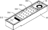
Fig. 3 is the assembling schematic diagram that the heat exchanger that is applicable to the closed rack according to the present invention is shown.
Fig. 4 (A) is the assembling flow path figure that illustrates according to heat exchanger of the present invention to Fig. 4 (D).
Fig. 5 is the profile that illustrates according to heat exchanger of the present invention.
Fig. 6 illustrates according to the parallel connection of heat exchanger of the present invention to expand schematic diagram.
Wherein, description of reference numerals is as follows:
1 rack, 10 heat exchangers
11 top fans, 12 bottom fans
15 outside air inlet 15 ' the outside air outlets
16 inner air inlet 16 ' the inner air outlets
Accommodation space on 17 heat pipes 101
102 times accommodation space 2 racks
20 heat exchangers, 21 top fans
22 bottom fans, 23 fin
25 ventilating openings, 26 ventilating openings
Accommodation space on 27 heat pipes 201
202 times accommodation spaces
3 heat exchangers, 30 enclosing covers
301 ventilation holes, 302 ventilation holes
31 bases, 311 base plates
3110 perforation of 312 accommodation spaces
32 heat exchange modules, 321 first heat sink assemblies
322 second heat sink assemblies, 323 heat pipes
3110 perforation, 3210 perforation
3220 perforation, 33 first fans
331 air intake vents, 332 air outlets
333 stators, 3330 fixing holes
34 second fans, 341 air intake vents
342 air outlets, 343 stators
3430 fixing holes, 4 racks
41 ventilating openings, 42 ventilating openings
351 baffle plates, 352 baffle plates
353 baffle plates, 354 baffle plates
Cold air C2 cold air after the C1 heat exchange
Hot-air after the H1 hot gas H2 heat exchange
Hot-air after cold air H2 ' the part heat exchange after the heat exchange of C1 ' part
Embodiment
Some exemplary embodiments that embody feature of the present invention and advantage will be described in detail in the explanation of back segment.Be understood that the present invention can have various variations on different schemes, its neither departing from the scope of the present invention, and explanation wherein and the Reference numeral usefulness that ought explain in itself, but not in order to restriction the present invention.
See also Fig. 3, it is the assembling schematic diagram that is applicable to the heat exchanger of closed rack according to the present invention.Heat exchanger 3 mainly comprises an enclosing cover 30, a base (chassis) 31, a heat exchange module 32, one first fan 33, one second fan 34 and a plurality of baffle plate 351~354.The left and right sides on enclosing cover 30 surfaces has a plurality of ventilation holes 301 and 302 respectively.It is open box-like that base 31 is substantially, and a plurality of perforation 3110 are arranged on the one base plate 311, and opposite side then forms an accommodation space 312.Heat exchange module 32 mainly comprises first heat sink assembly 321, second heat sink assembly 322 and a plurality of heat pipe (heat pipe) 323.First heat sink assembly 321 and second heat sink assembly 322 are all a plurality of fin and are spaced and form, and corresponding to 3110, the first heat sink assemblies 321 of the perforation on the base 31 and second heat sink assembly 322 a plurality of perforation 3210 and 3220 are arranged respectively.Coolant, for example water then are equipped with in heat pipe 323 inside.
See also Fig. 4 (A) to Fig. 4 (D) and cooperation Fig. 3, illustrate that now the assembling process of heat exchanger 3 is as follows:
At first, shown in Fig. 4 (A), utilize tight fit to be pressed into program (press fit operation), the perforation 3220 that makes heat pipe 323 pass perforation 3210, the perforation 3110 on the base 31 and second heat sink assembly 322 of first heat sink assembly 321 in regular turn is fixed in first heat sink assembly 321 on the base plate 311 of base 31 thus and second heat sink assembly 322 is fixed in the accommodation space 312 of base 31.
Then, shown in Fig. 4 (B), first fan 33 is placed on base plate 311 surfaces of base 31, wherein air intake vent 331 upwards, 332 of air outlets in first heat sink assembly 321 by the defined gas channel of a plurality of fin.Then outstanding stator 333 in air outlet 332 edges of first fan 33 and baffle plate 351 wherein have 3330 of a plurality of fixing holes to be placed on the adjacent heat pipe 323 on the stator 333.Then, baffle plate 352 is fixed on the heat pipe 323 of opposite side.In like manner, second fan 34 is placed the accommodation space 312 of base 31, wherein air intake vent 341 is downward, 342 of air outlets in second heat sink assembly 322 by the defined gas channel of a plurality of fin.Then outstanding stator 343 in second fan, 34 air outlet edges and baffle plate 353 wherein have a plurality of fixing holes 3430 and are placed on the adjacent heat pipe 323 on the stator 343.Then, baffle plate 354 is fixed on the heat pipe 323 of opposite side.
Then, enclosing cover 30 is covered on the said structure, finishes the assembling of heat exchanger 3 of the present invention immediately.Shown in Fig. 4 (C) and Fig. 4 (D), it is the front and the back side schematic perspective view of the heat exchanger 3 after assembling.
Please cooperate and see Fig. 5, illustrate that now the heat transfer mechanisms of heat exchanger 3 is as follows:
At first, running by second fan 34, make from the hot gas H1 of rack 4 inside by the ventilating opening 41 on rack 4 housings, air intake vent 341 by second fan 34 sucks, send in second heat sink assembly 322 by the defined gas channel of a plurality of fin by air outlet 342 again, hot gas contacts with heat pipe 323 with second heat sink assembly 322, with a part of heat transferred to the first heat sink assembly 321, then enter rack 4 inside by circulating by the ventilating opening on rack 4 housings 42 through cooled gas C1.Simultaneously, by pumping of first fan 33, extraneous cold air C2 then sucks by the ventilation hole 301 on enclosing cover 30 surfaces and the air intake vent 331 of first fan 33, send in first heat sink assembly 321 by the defined gas channel of a plurality of fin by air outlet 332 again, cold air contacts with heat pipe 323 with first heat sink assembly 321, further take away a part of heat, discharge extraneous via the ventilation hole 302 on enclosing cover 30 surfaces hot-air H2 again.Moreover baffle plate 351 contacts with the inwall of enclosing cover 30 substantially with 352, and baffle plate 353 contacts with the housing of rack 4 substantially with 354, thereby can avoid the air-flow phase mutual interference through heat exchange, thereby promotes heat exchanger effectiveness.
Please see Figure 6, another feature of heat exchanger of the present invention is that extendible two groups of above heat exchangers 3 in parallel to increase heat-sinking capability, only need get final product the interlock circuit parallel connection of adjacent heat exchanger 3, and those skilled in the art understand naturally.Therefore, the heat exchanger 3 in all runnings, in case arbitrary heat exchanger 3 faults are arranged, then other heat exchanger 3 still can continue running, all loses efficacy to avoid heat sinking function.In addition, if select for use the fan 33,34 of speed variable to allow heat-sinking capability by 0%~100% running, parallel technology then of the present invention can be when normal operation, design allows each heat exchanger 3 be the output of part heat-sinking capability, in case when arbitrary heat exchanger 3 faults were arranged, then other heat exchanger 3 reached the purpose of redundant for whole heat-sinking capabilities output.
In above embodiment, enclosing cover 30 and base 31 are by high conductivity material, and for example aluminium alloy is made.The fin of first heat sink assembly 321 and heat pipe 323 are also by high conductivity material, and for example copper or aluminum are made.First fan 33 and second fan 34 are preferably air blast (blower).In addition, because heat pipe 323 is provided with independently of one another, therefore, if when wherein only minority heat pipe 323 breaks, heat exchanger 3 still can continue to operate.Heat exchanger of the present invention for example can be installed on rack inside, outside, end face, side, the back side or the door, so can satisfy different installation requirements.
In sum, because the situation of air-flow phase mutual interference significantly improves, thereby the heat exchanger effectiveness of heat exchanger of the present invention improves significantly, so overall volume can be dwindled.Moreover, owing to adopt slim design, so even be installed on rack inside, too many inner space still can not account for.
Even if being described in detail by the above embodiments, the present invention can carry out modifying as all right neither scope of taking off by those skilled in the art as the desire protection of attached claim institute.
Claims (8)
1. a heat exchanger is applicable to the closed rack, and this heat exchanger comprises:
One base, it comprises the base plate with a plurality of first perforation;
One heat exchange module, it is fixed on this base, and defines first gas channel jointly with first side of this base plate, and defines second gas channel jointly with second side of this base plate;
One first fan, it is positioned at this first side of this base plate; And
One second fan, it is positioned at this second side of this base plate;
One first baffle plate and one second plate washer, this first baffle plate are arranged at the upper surface of this heat exchange module and are positioned at a side near this first fan, and this second baffle then is arranged at the upper surface of this heat exchange module and is positioned at opposite side with respect to this first baffle plate; And
One enclosing cover, in order to cover this first fan, this first side of this heat exchange module and this base plate, this enclosing cover also comprises a plurality of first ventilation holes and a plurality of second ventilation hole, and this first baffle plate and this second baffle substantially with this enclosing cover in side contacts, the cold air that comes from the outside passes through described first ventilation hole and this first fan of this enclosing cover by the running of this first fan, and enter this first gas channel and this heat exchange module and carry out heat exchange, discharge by described second ventilation hole again, and the running by this second fan enters this second gas channel and this heat exchange module carries out discharging after the heat exchange from the hot gas of this closed rack.
2. heat exchanger as claimed in claim 1 is characterized in that, this heat exchange module comprises:
First heat sink assembly, it is positioned on this first side of this base plate, and comprises a plurality of spaced fin, and to define this first gas channel, wherein each fin has second perforation of a plurality of described first perforation pattern corresponding to this base;
Second heat sink assembly, it is positioned on this second side of this base plate, and comprises a plurality of spaced fin, and to define this second gas channel, wherein each fin has the 3rd perforation of a plurality of described first perforation pattern corresponding to this base; And
A plurality of heat pipes, it passes described second perforation, described first perforation on this base and described the 3rd perforation of this second heat sink assembly of this first heat sink assembly in regular turn, thus this first heat sink assembly is fixed on this first side of this base plate and this second heat sink assembly is fixed on this second side of this base plate.
3. heat exchanger as claimed in claim 2, it is characterized in that described a plurality of heat pipes are pressed into mode with tight fit and pass described second perforation of this first heat sink assembly, described first perforation on this base and described the 3rd perforation of this second heat sink assembly.
4. heat exchanger as claimed in claim 3, it is characterized in that, this base also comprises four vertical with this base plate substantially side plates, so that this base is open box-like substantially, and the common accommodation space that forms of described four side plates of this base and this base plate, wherein this second fan and this second heat sink assembly are placed in this accommodation space.
5. heat exchanger as claimed in claim 4, it is characterized in that, outstanding one first stator in the air outlet edge of this first fan and this first baffle plate, this second baffle are positioned on this first heat sink assembly and this first baffle plate place outstanding with respect to the air outlet edge of this first fan.
6. heat exchanger as claimed in claim 5, it is characterized in that, outstanding one second stator in the air outlet edge of this second fan and one the 3rd baffle plate, and this heat exchanger also has one the 4th baffle plate, and the 4th baffle plate is positioned on this second heat sink assembly and the three baffle plate place outstanding with respect to the air outlet edge of this second fan.
7. heat exchanger as claimed in claim 6 is characterized in that, this first stator and this second stator have a plurality of fixing holes respectively and be placed on the adjacent heat pipe, and this enclosing cover covers this first heat sink assembly.
8. heat exchanger as claimed in claim 7 is characterized in that, the 3rd baffle plate and the 4th baffle plate substantially with the housing contacts of this rack.
Priority Applications (1)
| Application Number | Priority Date | Filing Date | Title |
|---|---|---|---|
| CNB2006100069591A CN100574591C (en) | 2006-01-26 | 2006-01-26 | Heat exchanger |
Applications Claiming Priority (1)
| Application Number | Priority Date | Filing Date | Title |
|---|---|---|---|
| CNB2006100069591A CN100574591C (en) | 2006-01-26 | 2006-01-26 | Heat exchanger |
Publications (2)
| Publication Number | Publication Date |
|---|---|
| CN101009991A CN101009991A (en) | 2007-08-01 |
| CN100574591C true CN100574591C (en) | 2009-12-23 |
Family
ID=38698011
Family Applications (1)
| Application Number | Title | Priority Date | Filing Date |
|---|---|---|---|
| CNB2006100069591A Expired - Fee Related CN100574591C (en) | 2006-01-26 | 2006-01-26 | Heat exchanger |
Country Status (1)
| Country | Link |
|---|---|
| CN (1) | CN100574591C (en) |
Families Citing this family (2)
| Publication number | Priority date | Publication date | Assignee | Title |
|---|---|---|---|---|
| CN201898686U (en) * | 2010-11-08 | 2011-07-13 | 中兴通讯股份有限公司 | Fan module and communication subrack |
| CN103066631B (en) * | 2012-06-08 | 2014-10-29 | 合肥海奥电气科技有限公司 | Electric bus on-board charger |
Citations (1)
| Publication number | Priority date | Publication date | Assignee | Title |
|---|---|---|---|---|
| US4449579A (en) * | 1981-01-30 | 1984-05-22 | Tokyo Shibaura Denki Kabushiki Kaisha | Cooling apparatus for a closed housing |
-
2006
- 2006-01-26 CN CNB2006100069591A patent/CN100574591C/en not_active Expired - Fee Related
Patent Citations (1)
| Publication number | Priority date | Publication date | Assignee | Title |
|---|---|---|---|---|
| US4449579A (en) * | 1981-01-30 | 1984-05-22 | Tokyo Shibaura Denki Kabushiki Kaisha | Cooling apparatus for a closed housing |
Also Published As
| Publication number | Publication date |
|---|---|
| CN101009991A (en) | 2007-08-01 |
Similar Documents
| Publication | Publication Date | Title |
|---|---|---|
| EP2040008B1 (en) | Outdoor unit of air conditioner | |
| US7631687B2 (en) | Heat exchanger | |
| US20090133423A1 (en) | Outdoor unit of air conditioner | |
| JP4778246B2 (en) | Wireless base station equipment | |
| CN104833011A (en) | Outdoor unit for air conditioner | |
| US20120087077A1 (en) | Server system with heat dissipation device | |
| CN101453856B (en) | Communication equipment | |
| CN102257711A (en) | Electric power source device | |
| CN2791583Y (en) | Plate-type heat exchanger | |
| CN100574591C (en) | Heat exchanger | |
| JP2004158641A (en) | Housing of electronic apparatus | |
| KR101166387B1 (en) | Out-door unit of an air conditioner | |
| CN102026520B (en) | Radiation device | |
| JP2004044962A (en) | Cooling device | |
| CN215412220U (en) | Automatically controlled box, outer machine of air conditioner and air conditioner | |
| CN216391914U (en) | Power equipment cabinet | |
| CN212278698U (en) | Outdoor air cooling machine box | |
| CN210624740U (en) | Electrical box assembly, outdoor unit and air conditioner | |
| CN205014512U (en) | Air conditioner outdoor unit | |
| JP3810475B2 (en) | Air conditioner | |
| CN220545325U (en) | Outdoor cabinet | |
| CN215723684U (en) | Frame air conditioner and air conditioner cabinet | |
| CN201528499U (en) | Heat radiating device | |
| CN219228207U (en) | Electric cabinet, outdoor unit and air conditioner | |
| CN218388394U (en) | Heat dissipation device for electrical control box of machining center |
Legal Events
| Date | Code | Title | Description |
|---|---|---|---|
| C06 | Publication | ||
| PB01 | Publication | ||
| C10 | Entry into substantive examination | ||
| SE01 | Entry into force of request for substantive examination | ||
| C14 | Grant of patent or utility model | ||
| GR01 | Patent grant | ||
| CF01 | Termination of patent right due to non-payment of annual fee |
Granted publication date: 20091223 Termination date: 20160126 |
|
| EXPY | Termination of patent right or utility model |