CN100555419C - Head for perpendicular recording with floating-trailing shield - Google Patents
Head for perpendicular recording with floating-trailing shield Download PDFInfo
- Publication number
- CN100555419C CN100555419C CNB2006101432597A CN200610143259A CN100555419C CN 100555419 C CN100555419 C CN 100555419C CN B2006101432597 A CNB2006101432597 A CN B2006101432597A CN 200610143259 A CN200610143259 A CN 200610143259A CN 100555419 C CN100555419 C CN 100555419C
- Authority
- CN
- China
- Prior art keywords
- floating
- pole piece
- trailing shield
- magnetic
- main pole
- Prior art date
- Legal status (The legal status is an assumption and is not a legal conclusion. Google has not performed a legal analysis and makes no representation as to the accuracy of the status listed.)
- Expired - Fee Related
Links
Images


Classifications
-
- G—PHYSICS
- G11—INFORMATION STORAGE
- G11B—INFORMATION STORAGE BASED ON RELATIVE MOVEMENT BETWEEN RECORD CARRIER AND TRANSDUCER
- G11B5/00—Recording by magnetisation or demagnetisation of a record carrier; Reproducing by magnetic means; Record carriers therefor
- G11B5/127—Structure or manufacture of heads, e.g. inductive
- G11B5/31—Structure or manufacture of heads, e.g. inductive using thin films
- G11B5/3109—Details
- G11B5/313—Disposition of layers
- G11B5/3143—Disposition of layers including additional layers for improving the electromagnetic transducing properties of the basic structure, e.g. for flux coupling, guiding or shielding
- G11B5/3146—Disposition of layers including additional layers for improving the electromagnetic transducing properties of the basic structure, e.g. for flux coupling, guiding or shielding magnetic layers
- G11B5/315—Shield layers on both sides of the main pole, e.g. in perpendicular magnetic heads
-
- G—PHYSICS
- G11—INFORMATION STORAGE
- G11B—INFORMATION STORAGE BASED ON RELATIVE MOVEMENT BETWEEN RECORD CARRIER AND TRANSDUCER
- G11B5/00—Recording by magnetisation or demagnetisation of a record carrier; Reproducing by magnetic means; Record carriers therefor
- G11B5/127—Structure or manufacture of heads, e.g. inductive
- G11B5/1278—Structure or manufacture of heads, e.g. inductive specially adapted for magnetisations perpendicular to the surface of the record carrier
-
- G—PHYSICS
- G11—INFORMATION STORAGE
- G11B—INFORMATION STORAGE BASED ON RELATIVE MOVEMENT BETWEEN RECORD CARRIER AND TRANSDUCER
- G11B5/00—Recording by magnetisation or demagnetisation of a record carrier; Reproducing by magnetic means; Record carriers therefor
- G11B5/127—Structure or manufacture of heads, e.g. inductive
- G11B5/147—Structure or manufacture of heads, e.g. inductive with cores being composed of metal sheets, i.e. laminated cores with cores composed of isolated magnetic layers, e.g. sheets
-
- G—PHYSICS
- G11—INFORMATION STORAGE
- G11B—INFORMATION STORAGE BASED ON RELATIVE MOVEMENT BETWEEN RECORD CARRIER AND TRANSDUCER
- G11B5/00—Recording by magnetisation or demagnetisation of a record carrier; Reproducing by magnetic means; Record carriers therefor
- G11B5/127—Structure or manufacture of heads, e.g. inductive
- G11B5/187—Structure or manufacture of the surface of the head in physical contact with, or immediately adjacent to the recording medium; Pole pieces; Gap features
- G11B5/1871—Shaping or contouring of the transducing or guiding surface
Landscapes
- Engineering & Computer Science (AREA)
- Manufacturing & Machinery (AREA)
- Physics & Mathematics (AREA)
- Electromagnetism (AREA)
- Magnetic Heads (AREA)
Abstract
Thereby the invention discloses and a kind ofly in recording medium, use a kind of floating-trailing shield to write the magnetic head that magnetic domain carries out perpendicular recording as the part of magnetic circuit.This floating-trailing shield is separated it by layer of non-magnetic material along its whole length with main pole piece, and its air supporting surface is basically greater than main pole piece.Magnetic resistance in floating-trailing shield and the recording medium between the bottom is quite low, so that both have identical mmf (or potential energy), thereby floating-trailing shield does not just need directly to be connected with yoke.When magnetic head is used for having storage system with the recording medium of soft bottom, the effect of this floating-trailing shield is when record and return pole piece magnetic short circuit.In the second embodiment of the present invention, floating-trailing shield extends to reduce off-track magnetic field around the side of main pole piece.
Description
The application is that the title of submitting on September 23rd, 2004 is " head for perpendicular recording with floating-trailing shield ", and application number is dividing an application of 200410011803.3 application for a patent for invention.
Technical field
The present invention relates to be used for the thin-film head of perpendicular recording, more specifically, relate to magnetic pole and magnetic shielding that is used for this magnetic head and the memory storage that uses this magnetic head.
Background technology
In the disk recording system of typical prior art, when the slider that comprises the magnetic transducer that is used for the read and write magnetic transition speeded along above disk, it was supported by suspender, and wherein disk is rotated by spindle drive motor.Disk comprises a plurality of films and at least one ferromagnetic thin film, and record (writing) head has write down the magnetic transition of therein information having been carried out coding in this ferromagnetic thin film.Magnetic domain in medium can longitudinally or vertically write.Utilize the film treatment technology, the reading head and the write head of this slider partly are built in the layer.Usually, at first make reading head, but also can at first make write head.Conventional write head is an induction type.
In adopting the disc driver of perpendicular recording, record-header is designed on perpendicular to the direction on disk plane direct magnetic flux and passes recording layer.Typically, the disk that is used for perpendicular recording has a hard magnetic recording layer and the soft bottom of a magnetic (magnetically soft underlayer).During utilizing the recording operation of single pole type head, direct magnetic flux vertically by hard magnetic recording layer, enters the plane of soft lining from the main pole piece of record-header then, and that returns this record-header again returns magnetic pole (return pole).The shape and size of main pole piece (main pole piece) and associated shield are to determine the principal element of track width.
The United States Patent (USP) 6531202 of authorizing people such as Litvinov is to be used for vertical or the vertical example of the magnetic recording media of record.This medium comprises that one is deposited on the soft bottom of magnetic on the substrate.The suitable soft magnetic material that is used for bottom it is said and comprises CoFe and alloy thereof, FeAIN, and NiFe, CoZrNb and FeTaN, wherein CoFe and FeAIN are preferred soft materials.The hard recording layer of one magnetic is deposited on the soft bottom.The suitable hard magnetic material that is used for recording layer it is said Co/Pd or the Co/Pt that comprises multilayer, and the L10 of CoPt, FePt, CoPd and FePd is (L10phase) mutually, and hcp Co alloy, and wherein this multilayer and L10 are preferred hard material mutually.
In U.S.'s publication application 2003/0151850 of people such as Nakamura, the single-pole-piece magnetic head with rail under the main pole piece (down-track) has been described.Main pole piece is made up of two parts at least, wherein the width of first under last rail (up-track) side direction rail one side along the direction sustainable growth of move media, the width of second portion on the direction of move media and the width at the following rail edge of first equates and under rail one side direction rail one side be constant along the direction of move media.It is said and avoided recording magnetic field intensity like this, and improved effective track width when the edge writes (side-writing) restraining, thereby realized having the magnetic recording disk equipment of high track density the weakening of magnetic track edge.
In the United States Patent (USP) RE 33949 that authorizes people such as Mallary, a single magnetic pole magnetic head that is used for perpendicular recording has been described, it comprised be connected to the back place write magnetic pole and at ABS place and write magnetic pole one closely spaced so-called " downstream shielding " (the following rail) of being separated by.The ABS face of shielding is designed to write face a lot of doubly big like that of pole parts, like this, very low and pattern precedence record of magnetic flux density in feeding the downstream magnetic shielding be not reversed or situation about weakening under, be enough to carry out perpendicular recording from the magnetic flux density of point.
The single magnetic pole magnetic head that is used for perpendicular recording with trailing shield (trailing shield) is the gradient that cost is improved with the intensity of field.In the prior art, trailing shield design needs: 1) oppositely fly upward gas outstanding (reverse flying air bearing) design, perhaps 2) before reading head, make write head 3) meticulous treatment step, thereby with trailing shield with return magnetic pole and link to each other.
Summary of the invention
Described use floating-trailing shield as the part of magnetic circuit being used for writing the head for perpendicular recording of magnetic domain at recording medium.Floating-trailing shield separates with main pole piece by a layer of non-magnetic material along its whole length, and the air supporting surface of floating-trailing shield (air bearing surface) is basically greater than the air supporting surface of main pole piece.Magnetic resistance in trailing shield and the recording medium between the bottom is quite low, makes both have identical mmf (or potential energy), like this, does not need direct the connection between floating-trailing shield and yoke (yoke).When magnetic head is used for storage system, and this storage system is when having the magnetic recording media that comprises soft bottom, and in fact floating-trailing shield is shorted to by magnetic during writing down and returns magnetic pole.Be shorted to the gradient that main pole piece has improved the field in the same way according to plane of the present invention floating-trailing shield and trailing shield magnetic.Owing to avoided trailing shield is connected to several required steps of return pole piece, the plane floating-trailing shield has been simplified the required treatment step of characteristic of incorporating trailing shield into.In the second embodiment of the present invention, floating-trailing shield extends around the side of main pole piece, thereby reduces offtrack (off-track) magnetic field.
According to an aspect of the present invention, provide a kind of thin film magnetic recording head that uses in magnetic recording media, comprising: a yoke comprises the main pole piece of a ferromagnetic material and the return pole piece of a ferromagnetic material; The floating-trailing shield of one ferromagnetic material, its be positioned at main pole piece with the return pole piece opposition side, nonmagnetic substance separates this floating-trailing shield with this yoke, wherein first magnetic resistance between this main pole piece and this floating-trailing shield is greater than second magnetic resistance between the soft bottom of magnetic in this floating-trailing shield and this magnetic recording media.
According to a further aspect in the invention, provide a kind of thin film magnetic recording head that in magnetic recording media, uses, comprising with the soft bottom of magnetic: a ferromagnetic material main pole piece; The return pole piece of one ferromagnetic material; One conductive metal layer, its main pole piece with the return pole piece opposite side on adjacent with this main pole piece; And the floating-trailing shield of a ferromagnetic material, itself and this conductive metal layer is adjacent, thus this conductive metal layer separates floating-trailing shield with main pole piece.
In accordance with a further aspect of the present invention, a kind of thin film magnetic recording head that uses in the magnetic recording media with the soft bottom of magnetic is provided, comprise: a yoke comprises that a main pole piece and that extends to the lip-deep ferromagnetic material of air supporting of this thin film magnetic recording head extends to the return pole piece of the lip-deep ferromagnetic material of air supporting of this thin film magnetic recording head; The floating-trailing shield of one ferromagnetic material, it is separated with this yoke by nonmagnetic substance, extend to the air supporting surface of this thin film magnetic recording head, and its on the air supporting surface, be positioned at main pole piece with return the magnetic pole opposite side, wherein first magnetic resistance between this main pole piece and this floating-trailing shield is greater than second magnetic resistance between this floating-trailing shield and the soft bottom of this magnetic.
According to another aspect of the invention, provide a kind of thin film magnetic recording head that uses in magnetic recording media, comprising: a yoke comprises the main pole piece of a ferromagnetic material and the return pole piece of a ferromagnetic material; The floating-trailing shield of one ferromagnetic material, its be positioned at main pole piece with the return pole piece opposition side, nonmagnetic substance separates this floating-trailing shield with this yoke, wherein this main pole piece has a tip, this tip extends to the hydraucone end points on the main pole piece from the air supporting surface of this thin film magnetic recording head, this floating-trailing shield has a thickness on perpendicular to the air supporting surface direction, this thickness is less than the length at the tip from the air supporting surface to the hydraucone end points.
According to another aspect of the invention, provide a kind of thin film magnetic recording head that uses in magnetic recording media, comprising: a yoke comprises the main pole piece of a ferromagnetic material and the return pole piece of a ferromagnetic material; The floating-trailing shield of one ferromagnetic material, its be positioned at main pole piece with the return pole piece opposition side, nonmagnetic substance separates this floating-trailing shield with this yoke, wherein this floating-trailing shield forms first and second side clearances extending along first and second sides around this main pole piece on the track direction.
Description of drawings
Fig. 1 is the figure perpendicular to the head portion of ABS according to first embodiment of the invention;
Fig. 2 is the figure according to the example magnetic head of first embodiment of the invention that watches from ABS;
Fig. 3 is the figure of example magnetic head around shielding of having according to second embodiment of the invention that watches from ABS;
Fig. 4 compares with the magnetic head that does not have floating-trailing shield, according to the B of the example magnetic head of first embodiment of the invention
yWith respect to following gauge from finite element model result curve figure;
Fig. 5 compares with the magnetic head that does not have floating-trailing shield, according to the dB of the example magnetic head of first embodiment of the invention
y/ dx with respect to following gauge from finite element model result curve figure;
The magnetic head of Fig. 6 right and wrong shielding is compared, and has been equipped with according to the B according to the magnetic head of second embodiment of the invention around shielding of the present invention
yThe finite element model result curve figure that crosses the track profile;
Fig. 7 is perpendicular to the figure of ABS acquisition according to head portion of the present invention, the magnetic potential energy when it has represented not have magnetic medium to exist;
Fig. 8 has represented for example memory device of disc driver, and it comprises according to magnetic head of the present invention and magnetic medium with the soft bottom of magnetic.That this magnetic head and medium partly are perpendicular to ABS and are obtained and the magnetic potential energy when having represented to have magnetic medium during operation.
Embodiment
Floating-trailing shield of the present invention can together use with the multiple magnetic head design that is used for perpendicular recording.From finite element model, under the situation that soft bottom exists, floating-trailing shield has reduced fringing field and has improved in the field gradient of descending on the rail direction.This improvement means better linear recording density.On the direction of crossing track (cross-track), floating-trailing shield has also improved fringing field, this means better to write the magnetic track sharpness.This design and traditional magnetic head work flow compatibility, and do not need oppositely to fly air-supported (reverse flying air-bearing).
By nonmagnetic substance, floating-trailing shield separates fully with main pole piece.Floating-trailing shield " is floated " with respect to main pole piece, even the non-magnetic gap material between main pole piece and the trailing shield provides a gap, in this gap, formed the longitudinal field of setting up by the mmf that electric current provided of magnetic head coil (head coil), and the thickness in this gap is used for controlling the flux that crosses the gap.Remove main vertical write field (H
y) outside also have longitudinal field (H
x) advantage 2 points are arranged: inclined field is (by H
yAnd H
xVector and formation) can more easily change the crystal grain of vertical orientation in magnetic recording media according to the Stoner-Wohlfarth transformation curve; Because bigger H
xAllow bigger dH
x/ dy is so can access bigger derivative dH
x/ dx, and according to Maxwell curl law, at the place that does not have current density, dH
y/ dx=dH
x/ dy.Like this, just obtain to cross over the controlled magnetic resistance in the gap between floating-trailing shield and the main pole piece.The inventor finds, under some condition that will discuss herein, does not need to use magnetic circuit that trailing shield is directly connected to and return magnetic pole.Under the condition of appointment, float shielding with return magnetic pole and have identical mmf.In the typical magnetic head that designs for perpendicular recording, the bottom of recording medium and the magnetic resistance that returns between the magnetic pole (P1 or auxiliary magnetic pole) are relatively low.If construct the magnetic resistance between the bottom in trailing shield and the recording medium very low,, so just do not need direct connection to such an extent as to they have identical mmf.
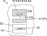
Fig. 1 has represented the part perpendicular to the magnetic head 20 of ABS according to first embodiment of the invention.Cross hatch is not to be used for representing type of material, but visual difference is provided between these elements.The ABS on the left side.As shown in the figure, layer forms from bottom to up, so reading head part at first forms in this design, and can be wrapped in forward the flight air supporting slider (flying air-bearingslider).Read transducer 35 by magnetic shielding S1 and S2 from flaning.Ferromagnetic writing component is from the P141 as return pole piece.Thereby P141 is connected by the center of coil 33 with P242 magnetic and finishes yoke.Coil 33 is from passing between P1 and the P2 and around the rear portion of yoke (not shown), thereby forms electromagnet.P1 extends to ABS and is not tapered, and P2 small distance place before ABS begins to attenuate, when arriving ABS or termination or be reduced to a small size.Preferably P2 does not extend to ABS, has only the shape of P343 to need Be Controlled like this.P3 be formed on P2 directly over, and contact with P2.P3 extends to ABS and has formed the main pole piece of ABS place write head.Although can't see in this figure, P3 is very narrow near the ABS place, and approximately from the hydraucone end points shown in Fig. 1 (flare point), P3 can expand and be wide many sizes, and at this point, P2 has reached its thickness completely.Above P3 deposit one deck nonmagnetic substance 37.This nonmagnetic substance can be a conducting metal, also can be aluminium oxide or another insulating material.On this layer nonmagnetic substance 37, form ferromagnetic floating-trailing shield 44 at the ABS place, it has extended a bit of distance from ABS to returning.Because magnetic recording media can direction as shown in Figure 1 move to the top from the bottom, floating-trailing shield 44 just becomes the following rail (tail) of main pole piece 41.Interval between the size of floating-trailing shield and floating-trailing shield and the P3 is extremely important to the performance of design.The area of choosing the floating-trailing shield at ABS place makes that the magnetic resistance between floating-trailing shield and the ferromagnetic medium is littler than the magnetic resistance between main pole piece P3 and the floating-trailing shield basically--coefficient is ten approximately at least.Thickness (degree of depth) perpendicular to the floating-trailing shield 44 of ABS is restricted, because along with the increase of thickness, write field can weaken.The distance that the thickness of preferred floating-trailing shield compares the hydraucone end points is little, and just the length than the tip of main pole piece P3 is little.It is unsaturated during operation that thereby floating-trailing shield must enough thickly make.
Distance between main pole piece P3 and the floating-trailing shield also is an important design parameter.This distance should be approximately with the distance apart from the soft bottom of main pole piece P343 and medium is identical during operation.
The space of floating-trailing shield back is filled with nonmagnetic substance 39.Although not shown, when any material that has comprised magnetic head is corroded easily or defiles, still need the film protective finish.Below, Reference numeral ABS will be used for the plane that presentation graphs 1 is labeled as the magnetic head of ABS, and no matter whether used protective finish.
Fig. 2 represented to watch from ABS with Fig. 1 magnetic head similarly according to the selection element of magnetic head of the present invention.Floating-trailing shield 44, main pole piece P343 and return pole piece P141 are provided with at ABS upper edge straight line usually.Floating-trailing shield 44 is rectangle in this embodiment, as long as but satisfy above-mentioned magnetic resistance standard, also can be other shapes.In this embodiment, the shape of the P3 of ABS place is trapezoidal, and its bottom is nearest from floating-trailing shield 44.The shape of P3 is not crucial for the function of floating-trailing shield 44, so can use other shape.
Fig. 7 and Fig. 8 are perpendicular to the part according to magnetic head of the present invention that ABS obtains.These figure have represented the relative mmf of return pole piece P141, main pole piece P343 and floating-trailing shield 44.Fig. 7 represents is potential energy when not having magnetic medium to exist.In this case, floating-trailing shield is actually maglev.What Fig. 8 represented is the magnetic storage apparatus 25 that has according to magnetic head of the present invention, such as disc driver, and has towards the magnetic medium 22 of the soft bottom 46 of magnetic head 20.In this case, floating-trailing shield 44 in fact with soft bottom 46 short circuits.Return pole piece P141, floating-trailing shield 44 and soft bottom 46 all are null value.Hard iron magnetic recording layer 47 does not play an important role in the magnetic circuit analysis.
Fig. 3 has represented the selection element according to the magnetic head of second embodiment of the invention of watching from ABS.In this embodiment, floating-trailing shield 44B is around the side of P3.In other words, P3 is arranged in the groove (channel) around floating-trailing shield 44B.Nonmagnetic substance 37B separates P3 on three sides with floating-trailing shield 44B.Thereby the advantage around floating-trailing shield 44B is can reduce the side write field to help to reduce track width.
Listed data that are to use business software to obtain among Fig. 4-6 by finite element model.The correlation parameter of model is: the magnetic pole of width 120nm, thickness 120nm, have gradually thin leading edge, and have the Road narrows (throat) of 400nm, the gap of 50nm, and the trailing shield Road narrows of 50nm (near the thickness of magnetic pole) perpendicular to ABS to trailing shield.The thickness that shields on the wafer minimum for 200nm (on the direction of rail down) and the width that is crossing the shielding of floating on the direction of track be 15 microns.These parameters are suitable for the situation that magnetic head and bottom are spaced apart 50nm, should adjust size pro rata when being used at interval other values of magnetic head and bottom.What can select is, can increase certain distance until greater than 1 micron at the center of distance main pole piece (magnetic track) perpendicular to the thickness of the shielding of ABS, thereby improve mechanical integrity (mechanical integrity) and allow some overlapping nonplanarity, but this is not crucial to operation of the present invention.Therefore in this model, the deep thickness of floating-trailing shield is added to about 200nm.
Fig. 4 compares with the magnetic head that does not have floating-trailing shield, according to the magnetic density B of the example magnetic head of first embodiment of the invention
yWith respect to following gauge from finite element model result's curve map.Show among the figure that floating-trailing shield is reducing magnetic density on the rail direction down.Maximum decrease is 0.3 tesla at about 0.07um place.
Fig. 5 compares with the magnetic head that does not have floating-trailing shield, according to the rate of change dB of the magnetic density of the example magnetic head of first embodiment of the invention
y/ dx with respect to following gauge from finite element model result's curve map.Data presentation, the rate of change of the magnetic density of floating-trailing shield of the present invention is bigger.
On following rail direction, it is similar with the performance of non-circulating type to be supposed to around floating-trailing shield 44B.Although with the complexity that improves processing is cost, can provide splendid result crossing on the direction of track around floating-trailing shield.In around floating-trailing shield, the scope of side clearance (side gap) should be magnetic head and bottom interval 1 to 2 times, preferably 1.5 times of magnetic head and bottom interval.Bigger side clearance distance makes that the reduction that writes is very little on adjacent orbit; Littler side clearance apart from meeting too much reduce the obtainable flux that writes.Fig. 6 is equipped with according to of the present invention around the magnetic head of floating-trailing shield and the magnetic density (B of non-shielding magnetic head
y) the finite element model result curve figure that crosses the track profile.In most of scope of the 0.3um that is simulated, magnetic density is by lower about 0.2 tesla.
Can use the thin film fabrication technology of standard to make according to magnetic head of the present invention.Although invention has been described with reference to specific embodiment, for use according to other of ferromagnetic structure of the present invention and use be still to those skilled in the art conspicuous.
Claims (8)
1. thin film magnetic recording head that uses in the magnetic recording media with the soft bottom of magnetic comprises:
The main pole piece of one ferromagnetic material;
The return pole piece of one ferromagnetic material;
One non magnetic conductive metal layer, its main pole piece with the return pole piece opposition side on adjacent with this main pole piece; And
The floating-trailing shield of one ferromagnetic material, itself and this conductive metal layer is adjacent, thus this conductive metal layer separates floating-trailing shield with main pole piece.
2. thin film magnetic recording head as claimed in claim 1, wherein first magnetic resistance between main pole piece and the floating-trailing shield is greater than second magnetic resistance between floating-trailing shield and the soft bottom of magnetic.
3. thin film magnetic recording head as claimed in claim 2, wherein this first magnetic resistance is roughly ten times of this second magnetic resistance.
4. thin film magnetic recording head as claimed in claim 1, wherein this main pole piece has a first area on the air supporting surface of this thin film magnetic recording head, and this floating-trailing shield has a second area on the air supporting surface, and this second area is greater than this first area.
5. thin film magnetic recording head as claimed in claim 1, wherein this main pole piece has a tip, and this tip extends to the hydraucone end points on the main pole piece from the air supporting surface of this thin film magnetic recording head; And
This floating-trailing shield has a thickness on perpendicular to the air supporting surface direction, this thickness is less than the length at the tip from the air supporting surface to the hydraucone end points.
6. thin film magnetic recording head as claimed in claim 1, wherein this floating-trailing shield has off-centered thickness on perpendicular to the air supporting surface direction, and this thickness is greater than the center thickness from the floating-trailing shield of air supporting surface observation.
7. thin film magnetic recording head that uses in magnetic recording media comprises:
One yoke comprises the main pole piece of a ferromagnetic material and the return pole piece of a ferromagnetic material;
The floating-trailing shield of one ferromagnetic material, its be positioned at main pole piece with the return pole piece opposition side, a non magnetic conductive metal layer separates this floating-trailing shield with this yoke,
Wherein this main pole piece has a tip, and this tip extends to the hydraucone end points on the main pole piece from the air supporting surface of this thin film magnetic recording head; And
This floating-trailing shield has a thickness on perpendicular to the air supporting surface direction, this thickness is less than the length at the tip from the air supporting surface to the hydraucone end points.
8. thin film magnetic recording head that uses in magnetic recording media comprises:
One yoke comprises the main pole piece of a ferromagnetic material and the return pole piece of a ferromagnetic material;
The floating-trailing shield of one ferromagnetic material, its be positioned at main pole piece with the return pole piece opposition side, a non magnetic conductive metal layer separates this floating-trailing shield with this yoke,
Wherein this floating-trailing shield forms first and second side clearances extending along first and second sides around this main pole piece on the track direction.
Applications Claiming Priority (2)
| Application Number | Priority Date | Filing Date | Title |
|---|---|---|---|
| US10/671,639 US7196871B2 (en) | 2003-09-26 | 2003-09-26 | Head for perpendicular recording with a floating trailing shield |
| US10/671,639 | 2003-09-26 |
Related Parent Applications (1)
| Application Number | Title | Priority Date | Filing Date |
|---|---|---|---|
| CNB2004100118033A Division CN1308919C (en) | 2003-09-26 | 2004-09-23 | Head for perpendicular recording with a floating trailing shield |
Publications (2)
| Publication Number | Publication Date |
|---|---|
| CN101059962A CN101059962A (en) | 2007-10-24 |
| CN100555419C true CN100555419C (en) | 2009-10-28 |
Family
ID=34376166
Family Applications (2)
| Application Number | Title | Priority Date | Filing Date |
|---|---|---|---|
| CNB2006101432597A Expired - Fee Related CN100555419C (en) | 2003-09-26 | 2004-09-23 | Head for perpendicular recording with floating-trailing shield |
| CNB2004100118033A Expired - Fee Related CN1308919C (en) | 2003-09-26 | 2004-09-23 | Head for perpendicular recording with a floating trailing shield |
Family Applications After (1)
| Application Number | Title | Priority Date | Filing Date |
|---|---|---|---|
| CNB2004100118033A Expired - Fee Related CN1308919C (en) | 2003-09-26 | 2004-09-23 | Head for perpendicular recording with a floating trailing shield |
Country Status (3)
| Country | Link |
|---|---|
| US (2) | US7196871B2 (en) |
| JP (1) | JP2005108411A (en) |
| CN (2) | CN100555419C (en) |
Families Citing this family (70)
| Publication number | Priority date | Publication date | Assignee | Title |
|---|---|---|---|---|
| US7729092B1 (en) * | 2002-11-07 | 2010-06-01 | Seagate Technology Llc | Shielded pole writer under reader |
| US7508624B1 (en) * | 2003-08-01 | 2009-03-24 | Lauer Mark A | Transducers for perpendicular recording with write pole tip angled toward media |
| US7196871B2 (en) * | 2003-09-26 | 2007-03-27 | Hitachi Global Storage Technologies Netherlands B.V. | Head for perpendicular recording with a floating trailing shield |
| US7042682B2 (en) * | 2003-10-17 | 2006-05-09 | Headway Technologies, Inc. | Fully shielded perpendicular recoding writer |
| JP4260002B2 (en) * | 2003-12-24 | 2009-04-30 | ヒタチグローバルストレージテクノロジーズネザーランドビーブイ | Magnetic head, manufacturing method thereof, and magnetic recording / reproducing apparatus |
| US7239478B1 (en) * | 2004-01-31 | 2007-07-03 | Western Digital (Fremont), Inc. | Write element for perpendicular recording in a data storage system |
| JP4118246B2 (en) * | 2004-03-31 | 2008-07-16 | Tdk株式会社 | Perpendicular magnetic recording head and manufacturing method thereof |
| US20050219743A1 (en) * | 2004-04-06 | 2005-10-06 | Headway Technologies, Inc. | Perpendicular write head with tapered main pole |
| US7253991B2 (en) * | 2004-04-30 | 2007-08-07 | Hitachi Global Storage Technologies Netherlands B.V. | Planar perpendicular recording head |
| US7414816B2 (en) * | 2004-05-28 | 2008-08-19 | Hitachi Global Storage Technologies Netherlands B.V. | Planar magnetic thin film head |
| US7649712B2 (en) * | 2004-08-31 | 2010-01-19 | Hitachi Global Storage Technologies Netherlands B.V. | Self aligned wrap around shield for perpendicular magnetic recording |
| JP3892023B2 (en) * | 2004-11-05 | 2007-03-14 | Tdk株式会社 | Perpendicular magnetic recording head, manufacturing method thereof, and magnetic recording apparatus |
| KR100668313B1 (en) * | 2004-11-15 | 2007-01-12 | 삼성전자주식회사 | Magnetic recording head |
| US7903372B2 (en) * | 2005-01-11 | 2011-03-08 | Samsung Electronics Co., Ltd. | Magnetic recording head and method of manufacturing the same |
| US7869160B1 (en) * | 2005-04-27 | 2011-01-11 | Western Digital (Fremont), Llc | Perpendicular recording head with shaped pole surfaces for higher linear data densities |
| KR100718127B1 (en) * | 2005-04-28 | 2007-05-14 | 삼성전자주식회사 | Perpendicular magnetic recording head |
| US7573683B1 (en) * | 2005-07-08 | 2009-08-11 | Maxtor Corporation | Write heads with floating side shields and manufacturing methods |
| JP2007035082A (en) * | 2005-07-22 | 2007-02-08 | Hitachi Global Storage Technologies Netherlands Bv | Perpendicular recording magnetic head and its manufacturing method |
| US20070035878A1 (en) * | 2005-08-10 | 2007-02-15 | Hung-Chin Guthrie | Perpendicular head with self-aligned notching trailing shield process |
| JP2007122840A (en) * | 2005-10-31 | 2007-05-17 | Toshiba Corp | Vertical magnetic recording device |
| US8054586B2 (en) * | 2005-11-23 | 2011-11-08 | Hitachi Global Storage Technologies Netherlands B.V. | Write head design and method for reducing adjacent track interference at very narrow track widths |
| US20070183093A1 (en) * | 2006-02-07 | 2007-08-09 | Quang Le | Protective layer for CMP assisted lift-off process and method of fabrication |
| JP4852330B2 (en) * | 2006-03-15 | 2012-01-11 | ヒタチグローバルストレージテクノロジーズネザーランドビーブイ | Perpendicular magnetic recording head and manufacturing method thereof |
| US7821736B2 (en) * | 2006-04-06 | 2010-10-26 | Hitachi Global Storage Technologies Netherlands, B.V. | Shaped trailing shield of a perpendicular recording write element |
| US7532432B2 (en) * | 2006-04-24 | 2009-05-12 | Hitachi Global Storage Technologies Netherlands B.V. | Perpendicular magnetic recording system with medium having thin soft underlayer and recording head having thick-throat trailing shield |
| US7576951B2 (en) * | 2006-04-25 | 2009-08-18 | Hitachi Global Storage Technologies Netherlands B.V. | Perpendicular magnetic write head having a magnetic write pole with a concave trailing edge |
| US7712206B2 (en) * | 2006-05-22 | 2010-05-11 | Hitachi Global Storage Technologies Netherlands B.V. | Method for manufacturing a magnetic write head having a trailing shield with an accurately controlled trailing shield gap thickness |
| US7768741B2 (en) * | 2006-05-22 | 2010-08-03 | Hitachi Global Storage Technologies Netherlands B.V. | Magnetic write head design for reducing wide area track erasure |
| US7639453B2 (en) * | 2006-08-01 | 2009-12-29 | Hitachi Global Storage Technologies Netherlands B.V. | Perpendicular magnetic write head with shunt structure to prevent read sensor interference |
| US7715147B2 (en) * | 2006-10-27 | 2010-05-11 | Hitachi Global Storage Technologies Netherlands B.V. | Magnetic write head having a shield that extends below the leading edge of the write pole |
| US8689430B1 (en) * | 2006-11-29 | 2014-04-08 | Western Digital (Fremont), Llc | Method for providing a perpendicular magnetic recording (PMR)head |
| JP2008198326A (en) * | 2007-01-17 | 2008-08-28 | Hitachi Ltd | Magnetic head and magnetic disk unit equipped with the same |
| US7467461B2 (en) * | 2007-03-20 | 2008-12-23 | Hitachi Global Storage Technologies Netherlands B.V. | Additive gap process to define trailing and side shield gap for a perpendicular write head |
| JP2008276817A (en) * | 2007-04-25 | 2008-11-13 | Tdk Corp | Perpendicular magnetic recording head |
| US7768744B2 (en) * | 2007-05-02 | 2010-08-03 | Hitachi Global Storage Technologies Netherlands B.V. | Perpendicular magnetic recording write head with coplanar main pole and return poles and magnetic recording system |
| US8051552B2 (en) * | 2007-05-11 | 2011-11-08 | Hitachi Global Storage Technologies Netherlands, B.V. | Stitched wrap around shield fabrication for perpendicular magnetic recording write heads |
| US7995307B2 (en) * | 2007-07-19 | 2011-08-09 | Hitachi Global Storage Technologies Netherlands B.V. | Perpendicular magnetic recording write head with trailing shield having throat height defined by electroplated nonmagnetic pad layer and method for making the head |
| US8015692B1 (en) | 2007-11-07 | 2011-09-13 | Western Digital (Fremont), Llc | Method for providing a perpendicular magnetic recording (PMR) head |
| US7788798B2 (en) * | 2007-11-21 | 2010-09-07 | Hitachi Global Storage Technologies Netherlands B.V. | Method for manufacturing a perpendicular magnetic write head with wrap around magnetic trailing and side shields |
| US7881010B2 (en) * | 2007-12-13 | 2011-02-01 | Hitachi Global Storage Technologies Netherlands B.V. | Process for self-aligned flare point and shield throat definition prior to main pole patterning |
| US7990651B2 (en) | 2007-12-13 | 2011-08-02 | Hitachi Global Storage Technologies Netherlands B.V. | Method of manufacturing a perpendicular magnetic write head with stepped trailing magnetic shield with electrical lapping guide control |
| US20090195920A1 (en) * | 2008-01-31 | 2009-08-06 | Bonhote Christian R | Main pole bridge structure |
| US8179636B1 (en) * | 2008-03-05 | 2012-05-15 | Western Digital (Fremont), Llc | Method and system for providing a perpendicular magnetic recording writer |
| US8305709B2 (en) * | 2008-08-08 | 2012-11-06 | Tdk Corporation | Perpendicular magnetic head and magnetic recording system having non-magnetic region in shield layer |
| US8276258B1 (en) | 2008-08-26 | 2012-10-02 | Western Digital (Fremont), Llc | Method for fabricating a magnetic recording transducer |
| US8166631B1 (en) | 2008-08-27 | 2012-05-01 | Western Digital (Fremont), Llc | Method for fabricating a magnetic recording transducer having side shields |
| US8720044B1 (en) | 2008-09-26 | 2014-05-13 | Western Digital (Fremont), Llc | Method for manufacturing a magnetic recording transducer having side shields |
| US8231796B1 (en) | 2008-12-09 | 2012-07-31 | Western Digital (Fremont), Llc | Method and system for providing a magnetic recording transducer having side shields |
| US8472286B2 (en) * | 2008-12-31 | 2013-06-25 | HGST Netherlands B.V. | Near field transducer having main body and wings extending therefrom and only electrically coupled thereby |
| US8291743B1 (en) * | 2009-05-27 | 2012-10-23 | Western Digital (Fremont), Llc | Method and system for calibrating an electronic lapping guide for a beveled pole in a magnetic recording transducer |
| US8472136B2 (en) * | 2009-07-13 | 2013-06-25 | Seagate Technology Llc | Write pole with a synthesized low magnetization shield |
| JP4693923B2 (en) * | 2009-09-29 | 2011-06-01 | 株式会社東芝 | Magnetic head and disk device provided with the same |
| US8411390B2 (en) * | 2009-10-16 | 2013-04-02 | Hitachi Global Storage Technologies Netherlands B.V. | Integrated half coil structure for write assist of high coercivity media |
| US8498078B2 (en) * | 2009-12-09 | 2013-07-30 | HGST Netherlands B.V. | Magnetic head with flared write pole having multiple tapered regions |
| US8451560B2 (en) * | 2009-12-09 | 2013-05-28 | HGST Netherlands B.V. | Magnetic head with flared write pole with multiple non-magnetic layers thereover |
| US8233235B2 (en) * | 2009-12-09 | 2012-07-31 | Hitachi Global Storage Technologies Netherlands B.V. | PMR writer having a tapered write pole and bump layer and method of fabrication |
| US8553360B2 (en) * | 2009-12-09 | 2013-10-08 | HGST Netherlands B.V. | Magnetic recording head having write pole with higher magnetic moment towards trailing edge |
| US8902548B2 (en) | 2010-04-30 | 2014-12-02 | Seagate Technology Llc | Head with high readback resolution |
| US8422177B2 (en) | 2010-04-30 | 2013-04-16 | Seagate Technology Llc | Reader shield with tilted magnetization |
| US8477453B2 (en) * | 2010-05-05 | 2013-07-02 | Headway Technologies, Inc. | Perpendicular magnetic recording write head with milling defined track width |
| JP4956661B2 (en) * | 2010-10-15 | 2012-06-20 | 株式会社東芝 | Magnetic head and disk device provided with the same |
| US8254059B2 (en) | 2010-12-06 | 2012-08-28 | Hitachi Global Storage Technologies Netherlands B.V. | Perpendicular magnetic recording head with domain controlled side shield |
| US8797686B1 (en) | 2010-12-23 | 2014-08-05 | Western Digital (Fremont), Llc | Magnetic recording transducer with short effective throat height and method of fabrication |
| US8587900B2 (en) | 2011-05-24 | 2013-11-19 | HGST Netherlands B.V. | Radiator-cooled nanowire-based write assist |
| US8451563B1 (en) | 2011-12-20 | 2013-05-28 | Western Digital (Fremont), Llc | Method for providing a side shield for a magnetic recording transducer using an air bridge |
| US8628672B1 (en) | 2012-06-27 | 2014-01-14 | Western Digital (Fremont), Llc | Process for manufacturing a perpendicular magnetic recording writer pole with nonmagnetic bevel |
| US8980109B1 (en) | 2012-12-11 | 2015-03-17 | Western Digital (Fremont), Llc | Method for providing a magnetic recording transducer using a combined main pole and side shield CMP for a wraparound shield scheme |
| US8914969B1 (en) | 2012-12-17 | 2014-12-23 | Western Digital (Fremont), Llc | Method for providing a monolithic shield for a magnetic recording transducer |
| US9042051B2 (en) | 2013-08-15 | 2015-05-26 | Western Digital (Fremont), Llc | Gradient write gap for perpendicular magnetic recording writer |
| US9082423B1 (en) | 2013-12-18 | 2015-07-14 | Western Digital (Fremont), Llc | Magnetic recording write transducer having an improved trailing surface profile |
Family Cites Families (24)
| Publication number | Priority date | Publication date | Assignee | Title |
|---|---|---|---|---|
| FR2559294B1 (en) | 1984-02-03 | 1988-08-12 | Commissariat Energie Atomique | NOVEL MAGNETIC WRITE AND READ HEAD FOR PERPENDICULAR RECORDING AND MANUFACTURING METHOD THEREOF |
| US4656546A (en) | 1985-01-22 | 1987-04-07 | Digital Equipment Corporation | Vertical magnetic recording arrangement |
| US5075956A (en) * | 1988-03-16 | 1991-12-31 | Digital Equipment Corporation | Method of making recording heads with side shields |
| FR2645315B1 (en) | 1989-03-29 | 1991-05-31 | Commissariat Energie Atomique | MAGNETORESISTOR READING MAGNETIC HEAD FOR PERPENDICULAR RECORDING AND METHOD FOR PRODUCING SUCH A HEAD |
| US5550691A (en) | 1989-11-27 | 1996-08-27 | Censtor Corp. | Size-independent, rigid-disk, magnetic, digital-information storage system with localized read/write enhancements |
| US5550891A (en) * | 1992-03-13 | 1996-08-27 | Olympic Controls Corp. | Positioning apparatus for X-ray source |
| US5408373A (en) | 1993-03-15 | 1995-04-18 | International Business Machines Corporation | Integrated transducer-suspension assembly for vertical recording |
| CN1139795A (en) * | 1995-06-30 | 1997-01-08 | 大宇电子株式会社 | Multiplex film magnetic head assembly and making method |
| US6407891B1 (en) * | 1999-05-24 | 2002-06-18 | International Business Machines Corporation | Magnetic read/write head having electromagnetic field cancellation element |
| US6531202B1 (en) | 1999-11-29 | 2003-03-11 | Seagate Technology Llc | Perpendicular magnetic recording media with reduced-noise soft magnetic underlayer |
| JP2001331909A (en) * | 2000-05-23 | 2001-11-30 | Tdk Corp | Thin film magnetic head and its manufacturing method |
| US6710973B2 (en) | 2000-09-18 | 2004-03-23 | Hitachi, Ltd. | Single pole type recording head including tapered edges |
| KR100370404B1 (en) * | 2000-11-28 | 2003-01-30 | 삼성전자 주식회사 | A magnetic head |
| US6595955B2 (en) * | 2001-03-15 | 2003-07-22 | Specialized Health Products, Inc. | Safety shield for medical needles |
| US6954340B2 (en) | 2001-05-23 | 2005-10-11 | Seagate Technology Llc | Perpendicular magnetic recording head with nonmagnetic write gap greater than twice side shield gap distance |
| US6809899B1 (en) * | 2001-08-20 | 2004-10-26 | Western Digital (Fremont), Inc. | Magnetic heads for perpendicular recording with trapezoidal pole tips |
| US6943992B2 (en) | 2001-08-30 | 2005-09-13 | Headway Technologies, Inc. | Inverted write head for vertical recording |
| US20030117749A1 (en) * | 2001-12-20 | 2003-06-26 | Shukh Alexander M. | Perpendicular read/write head for use in a disc drive storage system |
| JP4088453B2 (en) | 2002-02-14 | 2008-05-21 | 株式会社日立グローバルストレージテクノロジーズ | Magnetic head for perpendicular recording and magnetic disk drive equipped with the same |
| US6842313B1 (en) * | 2002-04-08 | 2005-01-11 | Maxtor Corporation | Floating down stream perpendicular write head shield |
| WO2003096327A2 (en) * | 2002-05-13 | 2003-11-20 | Chitra Seshan | Magnetic recording head |
| US6950277B1 (en) * | 2002-10-25 | 2005-09-27 | Maxtor Corporation | Concave trailing edge write pole for perpendicular recording |
| JP4033795B2 (en) * | 2002-11-28 | 2008-01-16 | 株式会社日立グローバルストレージテクノロジーズ | Magnetic recording medium and magnetic recording apparatus equipped with the same |
| US7196871B2 (en) * | 2003-09-26 | 2007-03-27 | Hitachi Global Storage Technologies Netherlands B.V. | Head for perpendicular recording with a floating trailing shield |
-
2003
- 2003-09-26 US US10/671,639 patent/US7196871B2/en not_active Expired - Fee Related
-
2004
- 2004-09-23 CN CNB2006101432597A patent/CN100555419C/en not_active Expired - Fee Related
- 2004-09-23 CN CNB2004100118033A patent/CN1308919C/en not_active Expired - Fee Related
- 2004-09-24 JP JP2004276553A patent/JP2005108411A/en active Pending
-
2007
- 2007-02-20 US US11/708,958 patent/US7440230B2/en not_active Expired - Fee Related
Also Published As
| Publication number | Publication date |
|---|---|
| CN1308919C (en) | 2007-04-04 |
| US7196871B2 (en) | 2007-03-27 |
| CN101059962A (en) | 2007-10-24 |
| JP2005108411A (en) | 2005-04-21 |
| US7440230B2 (en) | 2008-10-21 |
| US20050068669A1 (en) | 2005-03-31 |
| CN1601609A (en) | 2005-03-30 |
| US20070146930A1 (en) | 2007-06-28 |
Similar Documents
| Publication | Publication Date | Title |
|---|---|---|
| CN100555419C (en) | Head for perpendicular recording with floating-trailing shield | |
| US7688546B1 (en) | Perpendicular magnetic recording head having nonmagnetic insertion layers | |
| US7639452B2 (en) | Magnetic head for perpendicular recording and fabrication process | |
| US8023231B2 (en) | Composite shield structure of PMR writer for high track density | |
| US6259583B1 (en) | Laminated yoke head with a domain control element | |
| US7464458B2 (en) | Method for manufacturing a self-aligned, notched trailing shield for perpendicular recording | |
| US6813115B2 (en) | Perpendicular magnetic recording head with improved write field gradient | |
| US6252748B1 (en) | Thin film magnetic head with widening outer layer of multi-layer pole | |
| US7609478B2 (en) | Magnetic writer pole with a graded magnetic moment | |
| US20110051288A1 (en) | Perpendicular magnetic recording system and write head with transverse auxiliary pole for fast switching of write pole magnetization | |
| US11682418B2 (en) | Areal density capability improvement with a main pole skin | |
| US7580222B2 (en) | Thin-film magnetic head, a head gimbal assembly and hard disk drive | |
| US20090017198A1 (en) | Thin-film magnetic head, method of manufacturing the same, head Gimbal assembly, and hard disk drive | |
| US7983009B2 (en) | Magnetic recording/reproducing system, and thin-film magnetic head having shield layers of specified widths | |
| US7085100B2 (en) | Magnetic head having a bilayer pole tip | |
| US10734015B1 (en) | Magnetic recording write head having YIG-heavy metal-YIG in write gap and side gap to maximize spin-orbit-coupling efficiency | |
| US6646827B1 (en) | Perpendicular magnetic recording head with write pole which reduces flux antenna effect | |
| US7990654B2 (en) | Perpendicular magnetic recording head | |
| US10891976B1 (en) | Areal density capability improvement with a main pole skin | |
| US4675766A (en) | Combined magnetic write and read head for a recording medium which can be magnetized perpendicularly | |
| JP2006318579A (en) | Thin film magnetic head, method for manufacturing the same, head gimbal assembly, and hard disk device | |
| US6989964B2 (en) | Magnetic head having a pole piece with a double pedestal structure | |
| JP2002216315A (en) | Perpendicular magnetic recording head and its manufacturing method |
Legal Events
| Date | Code | Title | Description |
|---|---|---|---|
| C06 | Publication | ||
| PB01 | Publication | ||
| C10 | Entry into substantive examination | ||
| SE01 | Entry into force of request for substantive examination | ||
| C14 | Grant of patent or utility model | ||
| GR01 | Patent grant | ||
| C56 | Change in the name or address of the patentee |
Owner name: HGST NETHERLANDS BV Free format text: FORMER NAME: HITACHI GLOBAL STORAGE TECH |
|
| CP01 | Change in the name or title of a patent holder |
Address after: Amsterdam Patentee after: Hitachi Global Storage Technologies Netherlands B. V. Address before: Amsterdam Patentee before: Hitachi Global Storage Tech |
|
| CF01 | Termination of patent right due to non-payment of annual fee |
Granted publication date: 20091028 Termination date: 20150923 |
|
| EXPY | Termination of patent right or utility model |