CN100518642C - Blood collection needle - Google Patents
Blood collection needle Download PDFInfo
- Publication number
- CN100518642C CN100518642C CNB2005100835721A CN200510083572A CN100518642C CN 100518642 C CN100518642 C CN 100518642C CN B2005100835721 A CNB2005100835721 A CN B2005100835721A CN 200510083572 A CN200510083572 A CN 200510083572A CN 100518642 C CN100518642 C CN 100518642C
- Authority
- CN
- China
- Prior art keywords
- bowl
- blood
- valve member
- needle
- shape
- Prior art date
- Legal status (The legal status is an assumption and is not a legal conclusion. Google has not performed a legal analysis and makes no representation as to the accuracy of the status listed.)
- Expired - Fee Related
Links
Images


Classifications
-
- F—MECHANICAL ENGINEERING; LIGHTING; HEATING; WEAPONS; BLASTING
- F16—ENGINEERING ELEMENTS AND UNITS; GENERAL MEASURES FOR PRODUCING AND MAINTAINING EFFECTIVE FUNCTIONING OF MACHINES OR INSTALLATIONS; THERMAL INSULATION IN GENERAL
- F16K—VALVES; TAPS; COCKS; ACTUATING-FLOATS; DEVICES FOR VENTING OR AERATING
- F16K15/00—Check valves
- F16K15/02—Check valves with guided rigid valve members
- F16K15/021—Check valves with guided rigid valve members the valve member being a movable body around which the medium flows when the valve is open
-
- A—HUMAN NECESSITIES
- A61—MEDICAL OR VETERINARY SCIENCE; HYGIENE
- A61B—DIAGNOSIS; SURGERY; IDENTIFICATION
- A61B5/00—Measuring for diagnostic purposes; Identification of persons
- A61B5/15—Devices for taking samples of blood
- A61B5/150007—Details
- A61B5/150015—Source of blood
- A61B5/15003—Source of blood for venous or arterial blood
-
- A—HUMAN NECESSITIES
- A61—MEDICAL OR VETERINARY SCIENCE; HYGIENE
- A61B—DIAGNOSIS; SURGERY; IDENTIFICATION
- A61B5/00—Measuring for diagnostic purposes; Identification of persons
- A61B5/15—Devices for taking samples of blood
- A61B5/150007—Details
- A61B5/150206—Construction or design features not otherwise provided for; manufacturing or production; packages; sterilisation of piercing element, piercing device or sampling device
- A61B5/150213—Venting means
-
- A—HUMAN NECESSITIES
- A61—MEDICAL OR VETERINARY SCIENCE; HYGIENE
- A61B—DIAGNOSIS; SURGERY; IDENTIFICATION
- A61B5/00—Measuring for diagnostic purposes; Identification of persons
- A61B5/15—Devices for taking samples of blood
- A61B5/150007—Details
- A61B5/150206—Construction or design features not otherwise provided for; manufacturing or production; packages; sterilisation of piercing element, piercing device or sampling device
- A61B5/150221—Valves
-
- A—HUMAN NECESSITIES
- A61—MEDICAL OR VETERINARY SCIENCE; HYGIENE
- A61B—DIAGNOSIS; SURGERY; IDENTIFICATION
- A61B5/00—Measuring for diagnostic purposes; Identification of persons
- A61B5/15—Devices for taking samples of blood
- A61B5/150007—Details
- A61B5/150374—Details of piercing elements or protective means for preventing accidental injuries by such piercing elements
- A61B5/150381—Design of piercing elements
- A61B5/150389—Hollow piercing elements, e.g. canulas, needles, for piercing the skin
-
- A—HUMAN NECESSITIES
- A61—MEDICAL OR VETERINARY SCIENCE; HYGIENE
- A61B—DIAGNOSIS; SURGERY; IDENTIFICATION
- A61B5/00—Measuring for diagnostic purposes; Identification of persons
- A61B5/15—Devices for taking samples of blood
- A61B5/150007—Details
- A61B5/150374—Details of piercing elements or protective means for preventing accidental injuries by such piercing elements
- A61B5/150381—Design of piercing elements
- A61B5/150473—Double-ended needles, e.g. used with pre-evacuated sampling tubes
-
- A—HUMAN NECESSITIES
- A61—MEDICAL OR VETERINARY SCIENCE; HYGIENE
- A61B—DIAGNOSIS; SURGERY; IDENTIFICATION
- A61B5/00—Measuring for diagnostic purposes; Identification of persons
- A61B5/15—Devices for taking samples of blood
- A61B5/150007—Details
- A61B5/150374—Details of piercing elements or protective means for preventing accidental injuries by such piercing elements
- A61B5/150534—Design of protective means for piercing elements for preventing accidental needle sticks, e.g. shields, caps, protectors, axially extensible sleeves, pivotable protective sleeves
- A61B5/150572—Pierceable protectors, e.g. shields, caps, sleeves or films, e.g. for hygienic purposes
-
- A—HUMAN NECESSITIES
- A61—MEDICAL OR VETERINARY SCIENCE; HYGIENE
- A61B—DIAGNOSIS; SURGERY; IDENTIFICATION
- A61B5/00—Measuring for diagnostic purposes; Identification of persons
- A61B5/15—Devices for taking samples of blood
- A61B5/153—Devices specially adapted for taking samples of venous or arterial blood, e.g. with syringes
- A61B5/154—Devices using pre-evacuated means
-
- A—HUMAN NECESSITIES
- A61—MEDICAL OR VETERINARY SCIENCE; HYGIENE
- A61B—DIAGNOSIS; SURGERY; IDENTIFICATION
- A61B5/00—Measuring for diagnostic purposes; Identification of persons
- A61B5/15—Devices for taking samples of blood
- A61B5/150007—Details
- A61B5/150732—Needle holders, for instance for holding the needle by the hub, used for example with double-ended needle and pre-evacuated tube
Landscapes
- Health & Medical Sciences (AREA)
- Life Sciences & Earth Sciences (AREA)
- Engineering & Computer Science (AREA)
- Medical Informatics (AREA)
- Surgery (AREA)
- Hematology (AREA)
- Biophysics (AREA)
- Pathology (AREA)
- Biomedical Technology (AREA)
- Heart & Thoracic Surgery (AREA)
- Veterinary Medicine (AREA)
- Molecular Biology (AREA)
- Physics & Mathematics (AREA)
- Animal Behavior & Ethology (AREA)
- General Health & Medical Sciences (AREA)
- Public Health (AREA)
- Manufacturing & Machinery (AREA)
- General Engineering & Computer Science (AREA)
- Mechanical Engineering (AREA)
- Measurement Of The Respiration, Hearing Ability, Form, And Blood Characteristics Of Living Organisms (AREA)
Abstract
The present invention provides a blood collection needle which includes a needle for puncturing a patient's skin; a needle for puncturing a rubber plug which seals a blood collection tube; a hub for securing respective proximal portions of the two needles; a resilient cap fitted to the hub; and a valve member disposed in the internal passage of the hub which allows only blood flow from the needle used to puncture a patient's skin to the needle used to puncture the rubber plug which seals the blood collection tube. The valve member includes a bowl portion disposed so that its opening is faced toward the needle for puncturing the rubber plug and a guiding portion provided on a bottom surface of the bowl portion for causing the valve member to move to a predetermined position which closes the internal passage.
Description
Technical field
The present invention relates to a blood taking needle, more definite point is said and is related to a kind of blood taking needle, puncture the blood vessel of an object and the other end is inserted a vacuum test tube by a end with this blood taking needle, so just the inside of the inside of blood vessel and vacuum test tube is connected and be used to gather blood, can gather the blood of some according to the negative pressure of vacuum test tube thus.
Background technology
So far, a kind of blood sampling parts are used always, this blood sampling parts be suitable for vacuum test tube can repeatedly draw blood by a single aperture (as U.S. Patent number 5,222,502 and 5,303,713, Fig. 5).Such blood sampling parts comprise a blood taking needle, it is provided with a pin that can puncture patient skin, the pin that can puncture the rubber stopper of vacuum test tube, can fix the central module of the pin of these pins, with the elasticity tip that is contained on the pin, thereby be used for puncturing the vacuum test tube blood of packing into; The blood taking tube retainer is blood taking needle and being installed on the blood taking tube fixedly; The effective rubber closure sealing of vacuum blood collection.
In order to take a blood sample, blood taking needle at first is fixed on the blood taking tube retainer.Vacuum test tube is installed on the blood taking tube retainer, and thus, the pin that punctures vacuum test tube exposes out from the elasticity tip and vacuum test tube is poked, and begins blood sampling.
When the blood sampling parts were taken a blood sample, before acupuncture was broken, the internal pressure in the patient's blood vessel was increased by driving the blood parts.Yet when driving the blood parts and unclamp in blood collection procedure, the internal pressure of the built-in pressure ratio blood taking tube in the blood vessel is low, so the blood in the blood taking tube may flow back in the blood vessel.Because blood taking tube is normally unsterilized, its inside may be by germ contamination, or blood taking tube may comprise the chemical substance as blood clotting agent, and the injury that is caused along with blood enters in the patient body by backflow or the chemical substance of antibacterial is that our institute is undesired.
Such problem can be at least by considering that unclamping the time of driving the blood parts is solved.Yet, because blood collecting technology is inconsistent, the development of a kind of like this blood taking needle of people's expectation, it can avoid blood to be back to the patient's blood vessel from blood taking tube, does not unclamp the time of driving the blood parts and do not rely on.
Such as, the blood taking needle that can avoid blood to reflux that has check valve is developed (as U.S. Patent number 3557778, JP-A-53-97289, JP-A-57-11661, and JP-A-56-143144).Disclosed blood taking needle comprises a ball valve at the central module of pin in U.S. Patent number 3557778, when the internal pressure in the patient's blood vessel is reduced to internal pressure in the blood taking tube, this ball valve is to a side shifting of the insertion patient body of pin, thereby the immediate part of clog needle has so just avoided blood to be back in patient's the health.Disclosed blood taking needle comprises a tubular valve that is positioned at the central module of pin in JP-A-56-143144, because pressure differential, the mobile blood that prevented of this valve is back in patient's the health.On the other hand, the blood taking needle of being announced in JP-A-53-97289 and JP-A-57-11661 comprises a duckbill valve at the center of pin, it only allows unidirectional blood flow, when the blood backflow took place, this valve cut out according to blood flow, thereby has prevented that blood is back in the blood vessel.
The blood taking needle of above-mentioned use check valve can avoid blood to be back in patient's the body.Although yet the blood taking needle that has ball valve or tubular valve is applicable to owing to intravascular pressure and the intrinsic pressure pressure reduction of blood taking tube cause and moves or distortion, still pressure differential occurring and finishing the difference that has moment between mobile or the distortion, if pressure difference value is very little, move or distortion just can not occur, the situation that the backflow of blood can not be avoided fully therefore will occur.And the duckbill valve costliness is again disposable product, has so just increased the cost of the blood taking needle that has this valve.
Therefore, a target of the present invention just provides a kind of like this blood taking needle: can make a response rapidly to the backflow of blood, when the intrinsic pressure pressure reduction of intravascular pressure and vacuum test tube is very little, also can avoid the backflow of blood fully, and with low cost.
Summary of the invention
Be devoted to this research, the inventor finds that above problem can be solved by such blood taking needle: have the check valve of a novel shape, comprising the bowl-shape part and the targeting part that valve is moved along suitable direction at the center of pin that can block the blood of backflow.Obtained the present invention thus.
In other words, the present invention is:
(1) a kind of blood taking needle comprises: the needle tubing of a tip band sword is used to puncture patient's skin; The needle tubing of a tip band sword is used to puncture the rubber closure that seals blood taking tube; A central module is used for fixing the most contiguous separately part of two needle tubings, and has the inner passage two needle tubings are communicated with each other; A spring caps is installed in central module, so that surround the end of the needle tubing that inserts rubber closure in liquid-tight mode; With the valve member that is installed in the central module inner passage, it only allows blood to flow to the needle tubing that punctures rubber closure from the needle tubing that punctures patient.It is characterized in that this valve member comprises a bowl-shape part, its exit face also comprises a targeting part to the needle tubing that punctures rubber closure, and it is located on the bottom surface of bowl-shape part, and valve member is moved to the precalculated position of closing the inner passage;
(2) according to the blood taking needle of describing in (1), wherein the inner passage of central module comprises a cavity and a guide channel, this cavity holds the bowl-shape part of valve member, this guide channel holds the targeting part of valve member, and can by with the peripheral surface at the bowl-shape position of valve member in abutting connection with closing the inner passage;
(3) according to the blood taking needle of describing in (2), wherein that part in connection with the peripheral surface of the bowl-shape part of valve member of the guide channel of central module is formed with abutment surface, and this abutment surface has and bowl-shaped part is divided peripheral surperficial corresponding shape;
(4) according to any described blood taking needle in (1) to (3), wherein the bowl-shape part of valve member is hemispheric;
(5) according to any described blood taking needle in (1) to (3), wherein the bowl-shape part of valve member is conical;
(6) according to any described blood taking needle in (1) to (5), wherein the targeting part of valve member is three-dimensional columniform;
(7) according to any described blood taking needle in (1) to (5), wherein the targeting part of valve member is three-dimensional conical;
(8) according to (6) or (7) described blood taking needle, wherein targeting part is that bottom surface hollow and by bowl-shape position communicates with the opening at bowl-shape position.
(9) according to any described blood taking needle in (1) to (8), wherein central module comprises a ventilating duct, and it is logical that inner passage and outside atmosphere are connected with each other, one gas-pervious/the filter of saturating blood is not installed in the ventilating duct in liquid-tight mode;
(10) according to any described blood taking needle in (1) to (9), also comprise a spring members, this spring members promotes valve member along the direction of closing the inner passage, and this spring members is installed in the cavity of central module;
(11) according to (10) described blood taking needle, spring members wherein is clamped at the bowl-shape position of valve member and is used between the wall of a side that punctures rubber closure of needle tubing.
[advantage of invention]
Blood taking needle of the present invention can just, can not considered to unclamp the time of driving the blood parts under the situation of not considering blood collecting technology, thoroughly avoids the backflow of blood from the blood taking tube to the blood vessel.Among the present invention the check valve of blood taking needle compare with duckbill valve with low cost, than the check valve backflow of processing blood more fast of routine.
Description of drawings
Hereinafter, with reference to accompanying drawing, preference of the present invention will be described.Yet invention not only is confined to this.
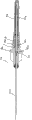
Fig. 1 is the longitudinal section of an example of expression blood taking needle of the present invention.
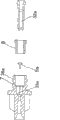
Fig. 2 is the longitudinal section of amplifying, demonstration be the exploded view of the central module of blood taking needle among Fig. 1.
Fig. 3 is the longitudinal section of another example of the check valve of blood taking needle among the present invention.
Fig. 4 is the longitudinal section of an example that has the blood taking needle of spring members among the present invention.
Fig. 5 is the longitudinal section of an example that has the blood taking needle of backflow mechanism among the present invention.
Fig. 6 is the longitudinal section of amplifying, demonstration be the exploded view of the central module of blood taking needle among Fig. 5.
The specific embodiment
According to the present invention, blood taking needle 1 comprises having two terminal needle tubings of point or sleeve pipe 21 and 22, and fixedly the central module 3 of needle tubing 21 and 22 near-end is enclosed within the spring caps 4 on the needle tubing 22, and is contained in the valve member 5 on the central module 3.
Among the present invention, needle tubing 21 and 22 is blank pipes, and its end 211 and 221 all is formed with sharp cutting edge.Terminal 211 are used to puncture patient's blood vessel, and terminal 221 is the rubber closures that sealing vacuum test tube in order to puncture.Cutting edge comprises the resistance that the facet (inclined-plane) of at least one inclination pierces through with minimizing.For needle tubing 21 and 22, metal material preferentially uses, as rustless steel, and aluminum, titanium or their alloy.
The central module 3 of this invention blood taking needle is provided with a rib 35 on the outer surface that punctures patient's one end.A rib 35 and a pin medicated cap engagement (do not have and show) are used for preventing the rotation of blood taking needle 1 at the pin medicated cap.Preferably the entire circumference at central module 3 is provided with two or more ribs 35 at interval with rule.
The known casting process of central module 3 usefulness of blood taking needle is cast in together among the present invention, as: with polypropylene, polyethylene, polystyrene, polyethylene terephthalate, polymethylpentene, Merlon, polyacrylonitrile or ABS resin jet molding method as material.
Described in hereinafter, because valve member 5 is installed in the inner passage, central module 3 preferentially is formed with a plurality of parts that are shaped separately as shown in Figure 2, and after valve member 5 was mounted and finishes, they were by welding or bonding becoming one.When the parts separately to central module 3 carry out cast molding, as shown in Figure 2, with the employing external part as shown in Figure 2 and the way of inner part difference molding, or the employing fore-end as shown in Figure 2 and the method for rear end part shaping.Yet the method for separation center parts helps the layout of valve member 5 less than limitation as long as it can be separated into different parts.
The bottom of the spring caps 4 that will engage with the bonding part 38 of central module 3 is columniform, and its size is large enough to hold the end 221 of needle tubing 22.The material of spring caps 4 can be a natural rubber, as the synthetic rubber of isoprene rubber or silicone rubber, and lactoprene.Similar with central module 3, spring caps 4 to small part is transparent or translucent.
Valve member 5 is placed on 33 li of cavitys, and guide channel 34 takes shape in the central module 3.The effect of valve member 5 is in the process of blood sampling, only allows blood to flow to vacuum test tube from patient's blood vessel, avoids blood to be back to the patient's blood vessel from vacuum test tube by blood taking tube 1.
Valve member 5 comprises a bowl-shape part 51 and a targeting part 52 that is located at the bottom of bowl-shape part 51 among the present invention, and this valve member is so placed, and allows the opening 53 of bowl-shape part 51 towards the neighbouring part 222 of the needle tubing 22 that is used for puncturing rubber closure.The shape of bowl-shape part 51 can be arbitrarily, as long as one of formation is bowl-shape, comprises bottom surface and side so that collect from the effusive blood of opening, taper shape as shown in Figure 1, hemispherical, cylindricality, rectangular cylinder.The shape of targeting part 52 can be three-dimensional taper or cylindricality, as shown in Figure 1, also can be the coalition of taper and cylindricality, shown in Fig. 3,5, or rectangular cylinder, preferably its outer dia is littler than the diameter of bowl part 51.Targeting part 52 can be hollow, and in the case, preferably, hollow inside is connected with the opening 53 of bowl-shape part 51 by the bottom of bowl-shape part 51.In other words, when the inside of targeting part 52 is hollow, also flow into the inside of targeting part 52 by the opening 53 mobile blood of bowl-shape part 51.
The material that constitutes valve member 5 comprises rustless steel, polypropylene, Merlon, polyethylene, ABS resin etc.The method of valve member 5 molding comprises mold pressing, jet moulding etc.Valve member 5 can be with the whole mold of these formative methods among the present invention, perhaps as bowl-shape part 51 and targeting part 52 molding respectively, then by bonding, engages, welds, and methods such as inner mold form one.
The preferred following methods design of valve member 5: the outer dia of the opening 53 of bowl-shape part 51 is bigger near the inside diameter at position 222 than the needle tubing 22 that is used to puncture rubber closure.
The bowl-shape part 51 of valve member 5 is to be contained in the cavity 33 of central module 3, and the targeting part 52 of valve member 5 is contained in the guide channel 34 of central module 3.Therefore, cavity 33 and guide channel 34 communicate, cavity 33 and needle tubing support section 32, and guide channel 34 and needle tubing support section 31 also communicate.
Preferably, the size and dimension of cavity 33 and guide channel 34 is enough big, the bowl-shape part 51 and the targeting part 52 that hold valve member 5 respectively, and a space is provided, be used for enough blood flows of needle tubing 22 of an end of rubber closure of sealed vacuum blood taking tube to guarantee that in the process of blood sampling blood flows to puncture from the needle tubing 21 that punctures patient's blood vessel one end.Cavity 33 preferably cylindricality or with the corresponding shape of the outer surface of bowl-shape part 51, guide channel 34 preferably cylindricality or with the corresponding shape of the outer surface of targeting part 52.
When the diameter of cavity 33 was bigger than the diameter of needle tubing support section 32, as shown in Figure 1, the boundary face between cavity 33 and needle tubing support section 32 will form a wall surface 39.In when blood sampling, when blood when patient's blood vessel flows to vacuum test tube, the valve portion 5 among the present invention, because blood flows to needle tubing 22 from needle tubing 21, to needle tubing 22 extruding of the inner passage of central module 3, therefore, the opening 53 of bowl-shape part 51 abuts against on the wall surface 39 of cavity 33.
In the process of blood sampling, when intrinsic pressure in the patient's blood vessel is reduced to the intrinsic pressure level that is lower than in the vacuum test tube, the blood in the vacuum test tube will attempt to be back to by needle tubing 22 inner passage of central module 3, then, flow in the patient's blood vessel.Yet, blood taking needle 1 of the present invention has been arranged, when the blood that refluxes by needle tubing 22 flow to cavity 33, it flow to the inside of bowl-shape part 51, the needle tubing 21 squeezing valve parts 5 in the inner passage of central module 3.Therefore, the peripheral surface of bowl-shape part 51 and guide channel 34 are adjacent.Because the pressure of backflow blood, this adjacency has just constituted a kind of liquid-tight sealing state, and like this, the blood that flows to cavity 33 has just been avoided being back in guide channel 34 and the needle tubing 21.
Because the valve member 5 among the present invention comprises a bowl-shape part 51, is used for receiving the blood of backflow, it can reflux when taking place at blood, at once the inner passage of closing center's parts 3.In addition, because valve member 5 has guiding position 52 to be accommodated in the guide channel 34 of central module 3, when blood refluxes generation, valve member 5 can be to needle tubing 21 fast moving, and can not make valve member 5 produce or rotation, also guaranteed the peripheral surface of bowl-shape part 51 and the adjacency between the guide channel 34.
That part of abutment surface 341 that is formed with of the part that guide channel 34 and bowl-shape part 51 are adjacent, this abutment surface 341 has and the corresponding shape of the peripheral surface of bowl-shape part 51.In other words, preferably, when bowl-shape part 51 was as shown in Figure 1 conical, abutment surface 341 forms had the taper the same with the peripheral surface of bowl-shape part 51, and when bowl-shape part 51 was hemispherical, abutment surface 341 formed in the hemispherical of the peripheral surface that is recessed into the bowl-shape part of picture.
Can comprise further that according to blood taking needle 1 of the present invention a spring members 6 is as push mechanism, as shown in Figure 4.Spring members 6 is springs that formed by synthetic resin (as rustless steel, polypropylene, Merlon, ABS resin, polyethylene, polyether sulfone), be clipped between the opening 53 and wall surface 39 at bowl-shape position 51 of valve member 51 boundary member between the needle tubing support section 32 of wall surface 39 in the cavity 33 of cavity 33 and central module 3.Therefore, preferably, the end of the spring members 6 of bowl-shape position 51 1 sides has the diameter bigger than the opening 53 at bowl-shape position 51, or is contained on the opening 53.If desired, the end of the spring members of wall surface 39 1 sides can be contained on the wall surface 39 or on the rib 391.
Under compressed situation, spring members 6 is installed in the cavity 33 of central module 3, enables closing on the direction of inner passage, promptly towards the direction of needle tubing 21, promotes valve member 5.Therefore, by the thrust of regulating spring parts 6, even when the intrinsic pressure pressure reduction of the intrinsic pressure and vacuum test tube of patient's blood vessel is very little, valve member 5 also can move to needle tubing 21, thereby closes the inner passage, thus, has avoided the backflow of blood reliably.As long as can promote valve member 5, push mechanism not only is confined to spring members 6, and the elastomer of elastomeric element such as dish type also can use.
Blood taking needle 1 according to this invention can be the blood taking needle 1a with backflow mechanism, as shown in Figure 5.Blood taking needle 1a has and blood taking needle shown in Figure 11 essentially identical assembly, also is the same to the operation of valve member 5a.The difference of blood taking needle 1 and blood taking needle 1a is: central module 3a has a ventilating duct 7, and inner passage and outside atmosphere are communicated; Ventilative/the filter 8 of saturating blood is not contained in the ventilating duct in liquid-tight mode; Central module 3 is partially transparent or translucent at least, so that flow into the situation of central module 3 from visual examination blood.
In blood taking needle 1a, when needle tubing 21a punctures patient's blood vessel, air in needle tubing 21a and the air in the inner passage of central module 3a by from ventilating duct 7 via ventilative/the filter 8 of saturating blood is not discharged into the outside, therefore, among the blood flow needle-inserting tube 21a and be full of inner passage and the ventilating duct 7 of central module 3a, and by ventilative/the filter 8 of saturating blood does not stop.Transparent or semitransparent part by central module 3 is visually tested in the face of blood from the outer of blood taking tube 1a, has confirmed backflow.
As shown in Figure 5, the ventilating duct 7 of blood taking needle 1a is that 3 threaded section 36a and the part the spring caps 4a form from cavity 33a to central module.Yet it can form like this: extend from the inside of spring caps 4a the inside by central module 3a, is with an opening at central module 3a outer, perhaps uses the part of the needle tubing support component 32a of central module 3a as ventilating duct 7.
Ventilative/the filter 8 of saturating blood does not have concrete qualification, as long as it has aperture can allow air pass through and stops passing through of liquid, comprises a membrane filter or sintered filter.Yet, be preferably the sintered body that forms by polyethylene, polypropylene, polymethyl methacrylate, polystyrene or similar material etc.More preferably one has the polymeric filter of suction, when contacting with blood, by expanding, blocks the aperture of sintered body.As the suction polymer, there are starch and acrylates to form, the gross weight of its relative sintered filter of composition percentage rate is preferably 1% to 30%.More preferably, filter 8 is as shown in Figure 6 columniform, and needing only it can arrange with the check valve 5a in the inner passage of central module 3a, as shown in Figure 5.
Claims (8)
1. blood taking needle comprises:
Needle tubing with end of a skin that is used to puncture patient;
Needle tubing with end of a rubber closure that is used to puncture the sealing blood taking tube;
A central module, this central module are fixed the near-end separately of two needle tubings, and have the inner passage that two needle tubings are communicated with each other;
One is installed to the spring caps of central module in liquid-tight mode, so that the end of the needle tubing of rubber closure is thrust in sealing; With
A valve member that is placed in the central module inner passage, it only allows blood to flow to the needle tubing direction that punctures rubber closure from the needle tubing that punctures patient,
It is characterized in that,
This valve member comprises a bowl-shape part, the opening surface of this bowl-shape part is to the needle tubing that punctures rubber closure, the shape of this bowl-shape part is to form a bowl-shape shape, this shape comprises that bottom surface and side are so that can collect from the mobile blood of this opening, this valve member also comprises a targeting part, this targeting part is located on the bottom surface of bowl-shape part, makes valve member move to the precalculated position of closing this inner passage in the inner passage, and
Described targeting part is hollow, and the hollow inside of described targeting part is connected with the opening of described bowl-shape part by the bottom surface of described bowl-shape part.
2. according to the blood taking needle of claim 1, wherein the inner passage of central module comprises a cavity and a guide channel that holds the targeting part of valve member that holds the bowl-shape part of valve member, and the peripheral surface at the bowl-shape position that this guide channel can be by the adjacency valve member is closed the inner passage.
3. according to the blood taking needle of claim 2, wherein the part in connection with the peripheral surface of the bowl-shape part of valve member of the guide channel of central module is formed with abutment surface, and this abutment surface has and the corresponding shape of the peripheral surface of bowl-shape part.
4. according to the blood taking needle of claim 1, wherein the bowl-shape part of valve member has hemispherical.
5. according to the blood taking needle of claim 1, wherein the bowl-shape part of valve member has taper shape.
6. according to the blood taking needle of claim 1, wherein central module comprises: a ventilating duct, and this ventilating duct is communicated with inner passage and outside atmosphere, and they are communicated with each other; And one be installed in ventilative in this ventilating duct and the filter of saturating blood not in liquid-tight mode.
7. according to the blood taking needle of claim 1, the inner passage of wherein said central module comprises a cavity that holds the bowl-shape part of valve member, and described blood taking needle also comprises a spring members, this spring members promotes valve member along the direction of closing the inner passage, and this spring members is placed in the cavity of described central module.
8. according to the blood taking needle of claim 7, wherein said spring members be clamped at the bowl-shape position of valve member and described central module cavity be used for puncture between the wall of needle tubing one side of rubber closure.
Applications Claiming Priority (2)
| Application Number | Priority Date | Filing Date | Title |
|---|---|---|---|
| JP2004203093 | 2004-07-09 | ||
| JP2004203093A JP2006020934A (en) | 2004-07-09 | 2004-07-09 | Blood collection needle |
Publications (2)
| Publication Number | Publication Date |
|---|---|
| CN1718159A CN1718159A (en) | 2006-01-11 |
| CN100518642C true CN100518642C (en) | 2009-07-29 |
Family
ID=35149478
Family Applications (1)
| Application Number | Title | Priority Date | Filing Date |
|---|---|---|---|
| CNB2005100835721A Expired - Fee Related CN100518642C (en) | 2004-07-09 | 2005-07-11 | Blood collection needle |
Country Status (5)
| Country | Link |
|---|---|
| US (1) | US7267653B2 (en) |
| EP (1) | EP1614384B1 (en) |
| JP (1) | JP2006020934A (en) |
| CN (1) | CN100518642C (en) |
| AT (1) | ATE508688T1 (en) |
Families Citing this family (14)
| Publication number | Priority date | Publication date | Assignee | Title |
|---|---|---|---|---|
| US7666166B1 (en) | 2004-12-27 | 2010-02-23 | Blivic, Llc | Bloodless intravenous integrated catheter |
| CA2812981C (en) | 2007-03-07 | 2018-07-10 | Becton, Dickinson And Company | Safety blood collection assembly with indicator |
| US7918805B2 (en) * | 2007-09-27 | 2011-04-05 | Tyco Healthcare Group Lp | Phlebotomy needle with shape memory alloy flashback sensor |
| US8317812B2 (en) * | 2009-07-29 | 2012-11-27 | Wah Leong Lum | Lancet device with lance retraction |
| WO2011030282A1 (en) * | 2009-09-09 | 2011-03-17 | Poly Medicure Limited | Blood collection device |
| US9486162B2 (en) * | 2010-01-08 | 2016-11-08 | Ultrasonix Medical Corporation | Spatial needle guidance system and associated methods |
| CN103126688A (en) * | 2013-03-25 | 2013-06-05 | 熊艳芳 | Anti-reflux structure of blood taking needle |
| US10357192B2 (en) | 2013-05-15 | 2019-07-23 | Becton, Dickinson And Company | Vacuum pressure regulators for use during blood collection |
| AU2013389306B2 (en) | 2013-05-15 | 2017-03-16 | Becton, Dickinson And Company | Vacuum pressure regulators for use during blood collection |
| ES2654181T3 (en) * | 2014-11-12 | 2018-02-12 | Poly Medicure Limited | Needle assembly with reflux viewing chamber to draw blood or other fluid samples |
| CN104720827B (en) * | 2015-03-27 | 2017-06-16 | 河北鑫乐医疗器械科技股份有限公司 | A kind of blood sampling instrument backflow preventing structure and the blood taking needle comprising the structure |
| US20160287793A1 (en) * | 2015-04-02 | 2016-10-06 | XEND Medical, LLC | Hypodermic needle system having plunger |
| CN104757980A (en) * | 2015-04-22 | 2015-07-08 | 浙江灵洋医疗器械有限公司 | Blood return preventing collection needle |
| DE102016206356A1 (en) * | 2016-04-15 | 2017-10-19 | Robert Bosch Gmbh | Housing component with a hydraulic line and its manufacture |
Family Cites Families (15)
| Publication number | Priority date | Publication date | Assignee | Title |
|---|---|---|---|---|
| US3557778A (en) * | 1968-11-18 | 1971-01-26 | Elbert L Hughes | Blood specimen collection assembly |
| JPS50118321A (en) * | 1974-03-01 | 1975-09-17 | ||
| US4106497A (en) | 1977-02-04 | 1978-08-15 | Becton, Dickinson And Company | Multiple sample needle assembly with indicator means |
| JPS5486892U (en) * | 1977-12-01 | 1979-06-19 | ||
| US4307731A (en) * | 1978-06-15 | 1981-12-29 | Becton, Dickinson And Company | Multiple sampling needle having one-way valve |
| US4317456A (en) | 1980-03-10 | 1982-03-02 | Becton, Dickinson And Company | Multiple sample needle with anti-backflow valve |
| US4340068A (en) | 1980-06-18 | 1982-07-20 | Becton, Dickinson And Company | Multiple sample needle with vein entry indicator |
| US5222502A (en) | 1990-09-26 | 1993-06-29 | Terumo Kabushiki Kaisha | Blood collecting needle |
| CH685454A5 (en) * | 1992-03-11 | 1995-07-14 | Inventa Ag | Check valve. |
| US5334159A (en) * | 1992-03-30 | 1994-08-02 | Symbiosis Corporation | Thoracentesis needle assembly utilizing check valve |
| US5527284A (en) * | 1994-05-18 | 1996-06-18 | Randall E. Ohnemus | Single use syringes |
| US6050957A (en) * | 1998-07-01 | 2000-04-18 | Desch; Larry W. | Multiple-draw, variable suction syringe |
| WO2003018105A1 (en) * | 2001-08-23 | 2003-03-06 | Occupational & Medical Innovations Ltd | A valve for use with a syringe and which prevents backflow |
| JP3777595B2 (en) * | 2002-02-25 | 2006-05-24 | ニプロ株式会社 | Blood collection needle |
| EP1602328A1 (en) * | 2004-06-02 | 2005-12-07 | Becton, Dickinson and Company | Flashback Blood Collection Needle |
-
2004
- 2004-07-09 JP JP2004203093A patent/JP2006020934A/en active Pending
-
2005
- 2005-07-07 AT AT05014747T patent/ATE508688T1/en not_active IP Right Cessation
- 2005-07-07 US US11/175,167 patent/US7267653B2/en not_active Expired - Fee Related
- 2005-07-07 EP EP05014747A patent/EP1614384B1/en not_active Not-in-force
- 2005-07-11 CN CNB2005100835721A patent/CN100518642C/en not_active Expired - Fee Related
Also Published As
| Publication number | Publication date |
|---|---|
| ATE508688T1 (en) | 2011-05-15 |
| EP1614384A3 (en) | 2006-03-22 |
| JP2006020934A (en) | 2006-01-26 |
| EP1614384B1 (en) | 2011-05-11 |
| US20060009714A1 (en) | 2006-01-12 |
| CN1718159A (en) | 2006-01-11 |
| US7267653B2 (en) | 2007-09-11 |
| EP1614384A2 (en) | 2006-01-11 |
Similar Documents
| Publication | Publication Date | Title |
|---|---|---|
| CN100518642C (en) | Blood collection needle | |
| EP0478459B1 (en) | Blood collecting needle | |
| CA1113817A (en) | One-way evacuated tube stopper | |
| US20090105666A1 (en) | Needleless access port valve | |
| EP0385424B1 (en) | Spike connector for an infusion set | |
| JP5947754B2 (en) | Needleless sampling port | |
| NO321794B1 (en) | Medical valve with positive flow characteristic, and method of effecting positive fluid flow | |
| JP2005524841A (en) | Whole blood sampling device | |
| JPS5867238A (en) | Sample collecting apparatus | |
| US20080312576A1 (en) | Plunger-less syringe for controlling blood flow | |
| JPS649011B2 (en) | ||
| CN102711895A (en) | Placement needle and placement needle assembly | |
| US20210113811A1 (en) | Hub assembly | |
| CN100403983C (en) | Backflow preventing structure of blood sampler, lure needle, blood sampling needle and blood sampling holder | |
| US6579245B1 (en) | Device for underpressuring collection and dosage liquid samples, in particular for analytic tests | |
| CA3001540C (en) | Syringe | |
| JP3610568B2 (en) | Blood collection needle | |
| JPH04364831A (en) | Blood sampling needle | |
| JP3674946B2 (en) | Blood collection needle | |
| GB2136314A (en) | Filter and Method for Obtaining Blood Plasma Samples | |
| JPH04132541A (en) | Blood sampling needle | |
| JP2001299728A (en) | Blood drawing needle | |
| JP3674949B2 (en) | Blood collection needle | |
| JP2994588B2 (en) | Blood collection needle | |
| CN201227452Y (en) | Puncture needle for transfusion bottle |
Legal Events
| Date | Code | Title | Description |
|---|---|---|---|
| C06 | Publication | ||
| PB01 | Publication | ||
| C10 | Entry into substantive examination | ||
| SE01 | Entry into force of request for substantive examination | ||
| C14 | Grant of patent or utility model | ||
| GR01 | Patent grant | ||
| CF01 | Termination of patent right due to non-payment of annual fee | ||
| CF01 | Termination of patent right due to non-payment of annual fee |
Granted publication date: 20090729 Termination date: 20170711 |