CN100457032C - Installation body for body liquid sampling apparatus and method of manufacturing it - Google Patents
Installation body for body liquid sampling apparatus and method of manufacturing it Download PDFInfo
- Publication number
- CN100457032C CN100457032C CNB028152182A CN02815218A CN100457032C CN 100457032 C CN100457032 C CN 100457032C CN B028152182 A CNB028152182 A CN B028152182A CN 02815218 A CN02815218 A CN 02815218A CN 100457032 C CN100457032 C CN 100457032C
- Authority
- CN
- China
- Prior art keywords
- collecting device
- fluid collecting
- movable part
- puncture
- body fluid
- Prior art date
- Legal status (The legal status is an assumption and is not a legal conclusion. Google has not performed a legal analysis and makes no representation as to the accuracy of the status listed.)
- Expired - Lifetime
Links
Images


Classifications
-
- A—HUMAN NECESSITIES
- A61—MEDICAL OR VETERINARY SCIENCE; HYGIENE
- A61B—DIAGNOSIS; SURGERY; IDENTIFICATION
- A61B5/00—Measuring for diagnostic purposes; Identification of persons
- A61B5/15—Devices for taking samples of blood
- A61B5/150007—Details
- A61B5/150015—Source of blood
- A61B5/150022—Source of blood for capillary blood or interstitial fluid
-
- A—HUMAN NECESSITIES
- A61—MEDICAL OR VETERINARY SCIENCE; HYGIENE
- A61B—DIAGNOSIS; SURGERY; IDENTIFICATION
- A61B5/00—Measuring for diagnostic purposes; Identification of persons
- A61B5/15—Devices for taking samples of blood
- A61B5/150007—Details
- A61B5/150053—Details for enhanced collection of blood or interstitial fluid at the sample site, e.g. by applying compression, heat, vibration, ultrasound, suction or vacuum to tissue; for reduction of pain or discomfort; Skin piercing elements, e.g. blades, needles, lancets or canulas, with adjustable piercing speed
- A61B5/150061—Means for enhancing collection
- A61B5/150068—Means for enhancing collection by tissue compression, e.g. with specially designed surface of device contacting the skin area to be pierced
-
- A—HUMAN NECESSITIES
- A61—MEDICAL OR VETERINARY SCIENCE; HYGIENE
- A61B—DIAGNOSIS; SURGERY; IDENTIFICATION
- A61B5/00—Measuring for diagnostic purposes; Identification of persons
- A61B5/15—Devices for taking samples of blood
- A61B5/150007—Details
- A61B5/150053—Details for enhanced collection of blood or interstitial fluid at the sample site, e.g. by applying compression, heat, vibration, ultrasound, suction or vacuum to tissue; for reduction of pain or discomfort; Skin piercing elements, e.g. blades, needles, lancets or canulas, with adjustable piercing speed
- A61B5/150061—Means for enhancing collection
- A61B5/150099—Means for enhancing collection by negative pressure, other than vacuum extraction into a syringe by pulling on the piston rod or into pre-evacuated tubes
-
- A—HUMAN NECESSITIES
- A61—MEDICAL OR VETERINARY SCIENCE; HYGIENE
- A61B—DIAGNOSIS; SURGERY; IDENTIFICATION
- A61B5/00—Measuring for diagnostic purposes; Identification of persons
- A61B5/15—Devices for taking samples of blood
- A61B5/150007—Details
- A61B5/150358—Strips for collecting blood, e.g. absorbent
-
- A—HUMAN NECESSITIES
- A61—MEDICAL OR VETERINARY SCIENCE; HYGIENE
- A61B—DIAGNOSIS; SURGERY; IDENTIFICATION
- A61B5/00—Measuring for diagnostic purposes; Identification of persons
- A61B5/15—Devices for taking samples of blood
- A61B5/150007—Details
- A61B5/150374—Details of piercing elements or protective means for preventing accidental injuries by such piercing elements
- A61B5/150381—Design of piercing elements
- A61B5/150412—Pointed piercing elements, e.g. needles, lancets for piercing the skin
-
- A—HUMAN NECESSITIES
- A61—MEDICAL OR VETERINARY SCIENCE; HYGIENE
- A61B—DIAGNOSIS; SURGERY; IDENTIFICATION
- A61B5/00—Measuring for diagnostic purposes; Identification of persons
- A61B5/15—Devices for taking samples of blood
- A61B5/150007—Details
- A61B5/150374—Details of piercing elements or protective means for preventing accidental injuries by such piercing elements
- A61B5/150381—Design of piercing elements
- A61B5/150503—Single-ended needles
- A61B5/150519—Details of construction of hub, i.e. element used to attach the single-ended needle to a piercing device or sampling device
-
- A—HUMAN NECESSITIES
- A61—MEDICAL OR VETERINARY SCIENCE; HYGIENE
- A61B—DIAGNOSIS; SURGERY; IDENTIFICATION
- A61B5/00—Measuring for diagnostic purposes; Identification of persons
- A61B5/15—Devices for taking samples of blood
- A61B5/150007—Details
- A61B5/150374—Details of piercing elements or protective means for preventing accidental injuries by such piercing elements
- A61B5/150534—Design of protective means for piercing elements for preventing accidental needle sticks, e.g. shields, caps, protectors, axially extensible sleeves, pivotable protective sleeves
- A61B5/150541—Breakable protectors, e.g. caps, shields or sleeves, i.e. protectors separated destructively, e.g. by breaking a connecting area
-
- A—HUMAN NECESSITIES
- A61—MEDICAL OR VETERINARY SCIENCE; HYGIENE
- A61B—DIAGNOSIS; SURGERY; IDENTIFICATION
- A61B5/00—Measuring for diagnostic purposes; Identification of persons
- A61B5/15—Devices for taking samples of blood
- A61B5/150007—Details
- A61B5/150374—Details of piercing elements or protective means for preventing accidental injuries by such piercing elements
- A61B5/150534—Design of protective means for piercing elements for preventing accidental needle sticks, e.g. shields, caps, protectors, axially extensible sleeves, pivotable protective sleeves
- A61B5/150572—Pierceable protectors, e.g. shields, caps, sleeves or films, e.g. for hygienic purposes
-
- A—HUMAN NECESSITIES
- A61—MEDICAL OR VETERINARY SCIENCE; HYGIENE
- A61B—DIAGNOSIS; SURGERY; IDENTIFICATION
- A61B5/00—Measuring for diagnostic purposes; Identification of persons
- A61B5/15—Devices for taking samples of blood
- A61B5/150007—Details
- A61B5/150374—Details of piercing elements or protective means for preventing accidental injuries by such piercing elements
- A61B5/150534—Design of protective means for piercing elements for preventing accidental needle sticks, e.g. shields, caps, protectors, axially extensible sleeves, pivotable protective sleeves
- A61B5/15058—Joining techniques used for protective means
- A61B5/150618—Integrally moulded protectors, e.g. protectors simultaneously moulded together with a further component, e.g. a hub, of the piercing element
-
- A—HUMAN NECESSITIES
- A61—MEDICAL OR VETERINARY SCIENCE; HYGIENE
- A61B—DIAGNOSIS; SURGERY; IDENTIFICATION
- A61B5/00—Measuring for diagnostic purposes; Identification of persons
- A61B5/15—Devices for taking samples of blood
- A61B5/150007—Details
- A61B5/150374—Details of piercing elements or protective means for preventing accidental injuries by such piercing elements
- A61B5/150534—Design of protective means for piercing elements for preventing accidental needle sticks, e.g. shields, caps, protectors, axially extensible sleeves, pivotable protective sleeves
- A61B5/150694—Procedure for removing protection means at the time of piercing
- A61B5/150702—Procedure for removing protection means at the time of piercing fully automatically removed, i.e. the removing does not require any action by the user
-
- A—HUMAN NECESSITIES
- A61—MEDICAL OR VETERINARY SCIENCE; HYGIENE
- A61B—DIAGNOSIS; SURGERY; IDENTIFICATION
- A61B5/00—Measuring for diagnostic purposes; Identification of persons
- A61B5/15—Devices for taking samples of blood
- A61B5/151—Devices specially adapted for taking samples of capillary blood, e.g. by lancets, needles or blades
- A61B5/15101—Details
- A61B5/15103—Piercing procedure
- A61B5/15107—Piercing being assisted by a triggering mechanism
- A61B5/15113—Manually triggered, i.e. the triggering requires a deliberate action by the user such as pressing a drive button
-
- A—HUMAN NECESSITIES
- A61—MEDICAL OR VETERINARY SCIENCE; HYGIENE
- A61B—DIAGNOSIS; SURGERY; IDENTIFICATION
- A61B5/00—Measuring for diagnostic purposes; Identification of persons
- A61B5/15—Devices for taking samples of blood
- A61B5/151—Devices specially adapted for taking samples of capillary blood, e.g. by lancets, needles or blades
- A61B5/15101—Details
- A61B5/15115—Driving means for propelling the piercing element to pierce the skin, e.g. comprising mechanisms based on shape memory alloys, magnetism, solenoids, piezoelectric effect, biased elements, resilient elements, vacuum or compressed fluids
- A61B5/15117—Driving means for propelling the piercing element to pierce the skin, e.g. comprising mechanisms based on shape memory alloys, magnetism, solenoids, piezoelectric effect, biased elements, resilient elements, vacuum or compressed fluids comprising biased elements, resilient elements or a spring, e.g. a helical spring, leaf spring, or elastic strap
-
- A—HUMAN NECESSITIES
- A61—MEDICAL OR VETERINARY SCIENCE; HYGIENE
- A61B—DIAGNOSIS; SURGERY; IDENTIFICATION
- A61B5/00—Measuring for diagnostic purposes; Identification of persons
- A61B5/15—Devices for taking samples of blood
- A61B5/151—Devices specially adapted for taking samples of capillary blood, e.g. by lancets, needles or blades
- A61B5/15101—Details
- A61B5/15115—Driving means for propelling the piercing element to pierce the skin, e.g. comprising mechanisms based on shape memory alloys, magnetism, solenoids, piezoelectric effect, biased elements, resilient elements, vacuum or compressed fluids
- A61B5/15123—Driving means for propelling the piercing element to pierce the skin, e.g. comprising mechanisms based on shape memory alloys, magnetism, solenoids, piezoelectric effect, biased elements, resilient elements, vacuum or compressed fluids comprising magnets or solenoids
-
- A—HUMAN NECESSITIES
- A61—MEDICAL OR VETERINARY SCIENCE; HYGIENE
- A61B—DIAGNOSIS; SURGERY; IDENTIFICATION
- A61B5/00—Measuring for diagnostic purposes; Identification of persons
- A61B5/15—Devices for taking samples of blood
- A61B5/151—Devices specially adapted for taking samples of capillary blood, e.g. by lancets, needles or blades
- A61B5/15101—Details
- A61B5/15115—Driving means for propelling the piercing element to pierce the skin, e.g. comprising mechanisms based on shape memory alloys, magnetism, solenoids, piezoelectric effect, biased elements, resilient elements, vacuum or compressed fluids
- A61B5/15125—Driving means for propelling the piercing element to pierce the skin, e.g. comprising mechanisms based on shape memory alloys, magnetism, solenoids, piezoelectric effect, biased elements, resilient elements, vacuum or compressed fluids comprising a vacuum or compressed fluids
-
- A—HUMAN NECESSITIES
- A61—MEDICAL OR VETERINARY SCIENCE; HYGIENE
- A61B—DIAGNOSIS; SURGERY; IDENTIFICATION
- A61B5/00—Measuring for diagnostic purposes; Identification of persons
- A61B5/15—Devices for taking samples of blood
- A61B5/151—Devices specially adapted for taking samples of capillary blood, e.g. by lancets, needles or blades
- A61B5/15186—Devices loaded with a single lancet, i.e. a single lancet with or without a casing is loaded into a reusable drive device and then discarded after use; drive devices reloadable for multiple use
-
- A—HUMAN NECESSITIES
- A61—MEDICAL OR VETERINARY SCIENCE; HYGIENE
- A61B—DIAGNOSIS; SURGERY; IDENTIFICATION
- A61B5/00—Measuring for diagnostic purposes; Identification of persons
- A61B5/145—Measuring characteristics of blood in vivo, e.g. gas concentration, pH value; Measuring characteristics of body fluids or tissues, e.g. interstitial fluid, cerebral tissue
- A61B5/14532—Measuring characteristics of blood in vivo, e.g. gas concentration, pH value; Measuring characteristics of body fluids or tissues, e.g. interstitial fluid, cerebral tissue for measuring glucose, e.g. by tissue impedance measurement
Abstract
The present invention relates to an attachment (X) for body fluid sampling device, comprising: a lancing member (21) including a lancing needle (28); an analyzing implement (5) for obtaining information on a target component in body fluid; and an attachment main body (1) holding the lancing member (21) and the analyzing implement (5). The attachment main body (1) includes a movable member (3) movable with the analyzing implement (5) longitudinally of the lancing needle (28). The attachment main body (1) includes for example, a holder (2) for holding the lancing member (21). The holder (2) has an inner space (22) for movement of the lancing needle (28). The lancing needle (28) is held preferably as sealed in the inner space (22).
Description
Technical field
The fixing body and the manufacture method thereof that the present invention relates to be installed in the body fluid collecting device and use.Be particularly related to fixing body and manufacture method thereof in the body fluid collecting device that is applicable to function with concentration of measuring detected material.
Background technology
When the treatment diabetes, patient's blood glucose value was remained in normal range, the particularly important is patient's self blood glucose value management.Particularly,, just can not lack mensuration on ordinary days to blood glucose value for blood glucose value was remained in normal range for the insulin-dependent diabetics.On the other hand, go to medical institutions also pretty troublesome continually in order to measure blood glucose value, therefore, it is very practical need not go to medical institutions also can measure the pocket blood-sugar level measuring device of blood glucose value.
As the example of this pocket blood-sugar level measuring device, can enumerate for example the application's device shown in Figure 12.This blood-sugar level measuring device 8 is equipped with fixing body 7 in use.Fixing body 7 makes body 70 and puncture body 71 and biosensor 72 form one.In body 70, be provided with the receiving space 73 of placing puncture body 71.Receiving space 73 is provided with opening 74, and biosensor 72 just in time clogs this opening 74 and is fixed.Biosensor 72 provides the enzyme reaction place, does not indicate among the figure, and it has the reagent layer that includes enzyme and electron transport substance.On biosensor 72, be formed with the through hole 76 that the puncture needle 75 that can make puncture body 71 passes through.
When being difficult to take out the part blood sampling of body fluid, utilize blood-sugar level measuring device 8 massage puncture object position Sk, promote blood operation, reuse blood-sugar level measuring device 8 is pushed or the object position Sk that attracts to puncture, make blood be gathered in this, promote thus to take out body fluid from puncture object position Sk.In these actions, shown in imaginary line among the figure, the bossed trend of puncture object position Sk, but when biosensor 72 is fixed, then, will hinder the protuberance of puncture object position Sk because puncture object position Sk is crushed on the biosensor 72.As a result, just can not impel body fluid fully to take out.And when body fluid takes out deficiency, when carrying out blood-sugar level measuring, just competent blood flow volume can not be sent to biosensor, so that can produce evaluated error, even wrong measurement result.On the contrary, along with the difference of site of puncture, some position cutaneous protuberance is less, and the protuberance degree of skin also varies with each individual, and therefore, when puncture, skin can not contact with biosensor sometimes.
Utilize fixing body 7,, puncture needle 75 is exposed no matter then whether biosensor 72 is whole.On the other hand, consider the sanitary condition of puncture needle 75, must carry out sterilization processing puncture needle 75.For sterilization back antibacterial can not adhered to once more, need under puncture needle 75 is positioned over state in the confined space, to sterilize, all must keep air-tight state till when using.For realizing the appropriate sterilization processing of puncture needle 75, not only need puncture body 71 and biosensor 72 are made an integral body with body 70, and need fixing body 7 be packed with the packaging material of aluminium lamination stampings.That is, in the fixing body 7 of structure shown in Figure 12, the contained enzyme of itself and biosensor 72 and even biosensor 72 is separated and carry out the sterilization processing of puncture needle 75.
The sterilization processing of puncture needle 75 can be carried out with methods such as irradiating gamma-rays.For this reason, when carrying out the sterilization processing of puncture needle 75, if there is enzyme simultaneously, then enzyme will lose activity, or active the reduction.If this thing happens, will cause minute to prolong, make measured concentration be lower than actual concentrations, and can not obtain measured value accurately.
On the other hand, when the potassium ferricyanide is used as electron transport substance, make the potassium ferricyanide be reduced to potassium ferrocyanide by irradiating gamma-ray.In this case, when utilizing the amperometry method to measure oxidation current, in formed reduced form electron transport substance, except that containing by the enzyme reaction generation electron transport substance that irradiating gamma-ray is produced when also containing by sterilization.As a result, when applying voltage and make the oxidation of reduced form electron transport substance, the oxidation current value that flows through makes measured concentration be higher than actual concentrations greater than deserved value, so that has reduced the mensuration precision.
Summary of the invention
Thereby the object of the present invention is to provide and a kind ofly do not hinder promotion to take out body fluid, and can avoid the fixing body that carries out suitable concentration determination by the undesirable condition that the puncture needle sterilization causes by puncture object position.
A first aspect of the present invention is to provide a kind of body fluid collecting device fixing body, it is characterized in that, is mounted in the fixing body of the front end of body fluid collecting device, comprising: maintenance has the fixture of the puncture body of puncture needle; Be used for obtaining the analyzer of information of the detected material of relevant body fluid; With the movable part that keeps described analyzer, wherein, described movable part by being installed in along the axially movable mode of described puncture needle on the described fixture, can move forward and backward with the front end of the relative together described body fluid collecting device of described analyzer.
Above-mentioned fixing piece is provided with the inner space that above-mentioned puncture body is moved, and above-mentioned puncture needle is maintained in the above-mentioned inner space under air-tight state.
Above-mentioned fixing piece has the opening that is used to make above-mentioned inner space and external communications, and above-mentioned inner space forms the air-tight state by the sealing member latch openings.Also movable part can be fixed on the fixture, utilize the movable part latch openings, and realize the air-tight state of inner space.On the other hand, when puncture procedure, can make the motion of movable part relative fixed part, remove air-tight state.
Fixing body of the present invention is preferably with described movable part and keeps the top cover of described analyzer to be set on this movable part, and by unloading top cover, forms to make analyzer remain on state on the movable part.
Above-mentioned movable part is provided with first maintaining body that is used to keep above-mentioned analyzer, and above-mentioned top cover is provided with second maintaining body that is used to keep above-mentioned analyzer, and the retentivity of the above-mentioned analyzer of maintenance of above-mentioned first maintaining body is greater than above-mentioned second maintaining body.
Above-mentioned first maintaining body has a plurality of hook-shaped connection parts.Above-mentioned analyzer has through hole, and above-mentioned second maintaining body passes above-mentioned through hole, and has connection part, and above-mentioned connection part has the part greater than the through hole diameter.
Above-mentioned analyzer has substrate, is formed at first electrode and second electrode on this substrate, and the part of above-mentioned first and second electrodes remains on the above-mentioned movable part, and is outstanding to the side of above-mentioned movable part.
Above-mentioned puncture body forms one by fragile flange portion and above-mentioned fixing piece, and when applying load for above-mentioned puncture body vertically, above-mentioned puncture body can be moved with respect to above-mentioned fixing piece.
A second aspect of the present invention is to provide the manufacture method of a kind of body fluid collecting device with fixing body, it is characterized by, and it has:
Under air-tight state, puncture needle is remained on airtight operation on the fixing body body;
The above-mentioned fixing body body that keeps above-mentioned puncture needle is carried out germ-resistant sterilization process; With
Analyzer is remained on through the maintenance of the analyzer on the above-mentioned fixing body body of sterilization processing operation.
Above-mentioned analyzer keeps operation to be preferably being installed on the above-mentioned fixing body body by the top cover that will keep above-mentioned analyzer realizing.Certainly can not use top cover yet and analyzer is remained on the fixing body body.
Above-mentioned fixing body body has the inner space by opening and external communications, and above-mentioned airtight operation is by realizing with the above-mentioned opening of sealing member locking.
In the above-mentioned airtight operation, above-mentioned sealing member is fixed on the fixing body body by the ultrasound wave method of welding.
Above-mentioned airtight operation is included in the operation that makes movable part with the maintaining body that is used to keep above-mentioned analyzer and above-mentioned fixing piece formation one behind the fixture that form to keep above-mentioned puncture needle, thereby above-mentioned movable part can be seesawed with respect to above-mentioned fixing piece.And under the state that analyzer is remained on the movable part, also can analyzer be remained on the fixing body body by movable part is installed on the fixture.In this case, make operation that movable part and fixture form one can be not yet as the part of airtight operation, but carry out as another operation different with airtight operation.
Description of drawings
Fig. 1 is the exploded perspective view of fixing body one example of the present invention;
Fig. 2 A and Fig. 2 B are the profilograph of fixing body shown in Figure 1;
Fig. 3 is the profile of action that is used to illustrate the movable part of fixing body shown in Figure 1;
Fig. 4 A and Fig. 4 B are the enlarged drawing of the major part of fixing body shown in Figure 1;
Fig. 5 is the overall perspective view that is used for the biosensor of fixing body shown in Figure 1;
Fig. 6 is the exploded perspective view of biosensor shown in Figure 5;
Fig. 7 A~Fig. 7 C is the profile that is used to illustrate the manufacture method of fixing body shown in Figure 1;
Fig. 8 is for being installed in fixing body shown in Figure 1 the partial sectional view of the major part under the state on the body fluid collecting device;
Fig. 9 is the IX-IX line profile along Fig. 8;
Figure 10 A~Figure 10 D is the profile that is used to illustrate the puncture action that utilizes body fluid collecting device and fixing body;
Figure 11 is the enlarged drawing of the major part of the body fluid collecting device under the puncture state;
Figure 12 is for being installed in the fixing body of prior art the profile of the major part under the state on the blood-sugar level measuring device.
The specific embodiment
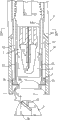
Below, with reference to the example of description of drawings body fluid collecting device of the present invention with fixing body.Fig. 1 is the exploded perspective view of body fluid collecting device of the present invention with an example of fixing body, and Fig. 2 is the profilograph of fixing body shown in Figure 1.
As depicted in figs. 1 and 2, fixing body X has fixing body body 1, top cover 4, puncture body 21 and the biosensor 5 that has fixture 2 and movable part 3.
On the other hand, puncture body 21 has maintaining part 27 and puncture needle 28.The front end of puncture needle 28 is outstanding by maintaining part 27.Puncture body 21 also has outwards outstanding flange 29.Whole peripheries of puncture body 21 all are provided with flange 29.Puncture body 21 forms one by flange 29 and body 20.Be thin wall shape between flange 29 and the body 20, when puncture body 21 was subjected to load more than the certain value, puncture body 21 broke away from from body 20.Whole peripheries of puncture body 21 all are provided with flange 29, and on the other hand, the opening 25 of its inner space 22 can be kept puncture needle 28 thus by locking under air-tight state.Puncture body 21 can not be integral with body 20 yet, but makes individual components.
As depicted in figs. 1 and 2, the body 30 of movable part 3 has cylindrical portion 33 and pick off installation portion 34.The upper surface 35 of pick off installation portion 34 is the plane.Distance between fixture 2 and movable part 3 is for hour, and the lower end of fixture 2 contacts with the upper surface 35 of pick off installation portion 34 by sealing member 26.
Be provided with the installed surface 36a that is used to install following pick off 5 (referring to Fig. 5 and Fig. 6) on the lower surface 36 of pick off installation portion 34, this installed surface 36a tilts with respect to the upper surface 35 of pick off installation portion 34.Shown in Fig. 3 and Fig. 4 A, being provided with two on installed surface 36a is two groups of connection parts 37 of one group.This connection part 37 is used for biosensor 5 is remained on movable part 3.Shown in Fig. 1, Fig. 2 B, the two ends of biosensor 5 are outstanding by movable part 3, under this state, are installed on the installed surface 36a.Corresponding therewith, as shown in Figure 1, be formed with breach 38 on the movable part 3.
The central authorities of pick off installation portion 34 are formed with through hole 39.When puncture body 21 was mobile downwards, puncture needle 28 made the front end of puncture needle 28 outstanding by the lower surface 36 of pick off installation portion 34 by through hole 39, and the diameter of through hole 39 is less than the diameter of the maintaining part 27 of puncture body 21.Therefore, when puncture body 21 was mobile downwards, the front end of maintaining part 27 formed interference by the upper surface 35 of 26 pairs of pick off installation portions 34 of sealing member, with moving of restriction puncture body 21.The result just can make the overhang of puncture needle 28 keep certain.
As depicted in figs. 1 and 2, top cover 4 has cylindrical body 40 that top is open state and by the outstanding upward a pair of installation sheet 41 of body 40.Front end at installation sheet 41 is formed with connection part 42.Shown in Fig. 2 A, this connection part 42 is corresponding position relation with the flange 23 of fixture 2, and connection part 42 hangs on the flange 23, top cover 4 can be installed on the body 1 of fixing body thus, and cover movable part 3.At this moment, shown in Fig. 2 B, the distance of fixture 2 and movable part 3 is minimum.
Shown in Fig. 1 and Fig. 2 A, by the outstanding upward object stage 43 that forms in the bottom surface of the body 40 of top cover 4.Object stage 43 is used to keep biosensor 5.Shown in Fig. 4 B, the upper surface 43a of object stage 43 and the installed surface 36a of movable part 3 certain angle that correspondingly tilts.And for example be somebody's turn to do figure and shown in Figure 1, the upper surface 43a of object stage 43 is provided with a pair of connection part 44.Shown in Fig. 4 B, utilize the through hole (referring to Fig. 5 and Fig. 6) of this connection part 44 and biosensor 5 that biosensor 5 is installed on the object stage 43.Biosensor 5 also can remain on the movable part 3, and makes the retentivity of the retentivity of movable part 3 greater than top cover 4.Thus, when taking off top cover 4 on by fixing body body 1, biosensor 5 can kept the state that remains on the movable part 3, and simultaneously can be with biosensor 5 by taking off on the top cover 4.And for example shown in Fig. 1 and Fig. 2 B, biosensor 5 is installed on the object stage 43, and its two ends are outstanding by top cover 4.Corresponding therewith, as shown in Figure 1, be formed with breach 45 on the top cover 4.
In this biosensor 5, on substrate 50, dividing plate 51 and lid 52, be formed with otch 53,58,59, the result just forms the semi-cylindrical recess 5A that opens along the short side direction of thickness direction and substrate on biosensor 5.As described below, this recess 5A becomes the receiving port of reception by the effusive blood of skin.In addition, in biosensor 5, form the stream 5B of the short side direction of cross-section substrate 50 by substrate 50, dividing plate 51 and lid 52.The end of this stream 5B is by recess 5A and external communications, and the other end also with external communications.Therefore, when by recess 5A input blood, just can utilize capillarity, blood is flowed to the other end.Be provided with reagent layer 57 in stream 5B, therefore, when blood flowed in stream 5B, reagent layer 57 will dissolve.At this moment, the glucose in the blood is oxidized because of enzyme reaction, and will reduce electron transport substance by electronics that this reaction produces.
As described below the making of above-mentioned fixing body X.And fixture 2, movable part 3 and top cover 4 are made by resin forming in advance, and puncture body 21 forms one with fixture 2.Biosensor 5 also is prefabricated.
At first, shown in Fig. 7 A, utilize the opening 25 of sealing member 26 locking fixtures 2.Like this, just can keep puncture needle 28 at air-tight state.And sealing member 26 can use the goods of being made by metallic films such as aluminum or resin sheet etc.Utilize the ultrasound wave method that welds that sealing member 26 is fixed on the fixture 2.When under air-tight state, keeping puncture needle 28, simultaneously fixture 2 and puncture body 28 are carried out sterilization processing.Sterilization processing is undertaken by irradiating gamma-ray.
Shown in Fig. 7 B, movable part 3 is installed on the fixture 2 then, forms fixing body body 1.Engage with the guiding recess 24 of fixture 2 by engaging claw 32, realize the installation of movable part 3 movable part 3.In this stage, biosensor 5 is not fixed on the movable part 3.
In addition, shown in Fig. 7 C, be installed on the fixing body body 1 by the top cover 4 that will keep biosensor 5, but with regard to the fixing body X shown in shop drawings 2 grades.In addition, shown in Fig. 4 B, the connection part 44 of top cover 4 pass the through hole 5 of biosensor 5 ' state under, biosensor 5 is installed on the top cover 4, and with its hook through hole 5 ' periphery edge on.In addition, shown in Fig. 7 C, top cover 4 is installed by the connection part 42 and the hook of the flange 23 of fixture 2 of top cover 4.Shown in Fig. 2 B, top cover 4 is being installed under the state of fixing body body 1, the front end of fixture 2 contacts by the upper surface 35 of sealing member 26 with the pick off installation portion 34 of movable part 3, and on the other hand, the front end of movable part 3 contacts with the bottom surface of the body 40 of top cover 4.That is, just in time movable part 3 is clipped between fixture 2 and the top cover 4.Just shown in Fig. 4 A, biosensor 5 is crushed on the installed surface 36a of movable part 3 result, thereby biosensor 5 is remained on the connection part 37 of movable part 3.
Utilize the manufacture method of this fixing body X, the sterilization of puncture needle 28 can be carried out under the state that breaks away from biosensor 5.Therefore,, can not make the oxidoreduction enzyme modification of the reagent layer 57 that constitutes biosensor 5 or lose activity, electron transport substance is reduced by sterilization processing.Therefore, the sterilization processing that does not have owing to puncture needle 28 makes the problem that precision reduces of measuring.
Because puncture needle 28 sterilizes under air-tight state, therefore, until removing (when using) till the air-tight state, puncture needle 28 can be by pollutions such as antibacterials.
Because the simple operations that can be installed on the fixing body body 1 by the top cover 4 that will keep biosensor 5 remains on biosensor 5 on the movable part 3, so operability is good.
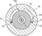
As Fig. 8 and shown in Figure 9, fixing body X is mounted on the front end 60 of body fluid collecting device Y and uses.Under the contacted state of flange 64a, 64b on the inner surface of fixture 2 and the front end 60 that is located at body fluid collecting device Y, fixing body X is entrenched on the front end 60 of body fluid collecting device Y.Be fixed on flange 64a, the 64b of body fluid collecting device Y because fixture 2 is chimeric, therefore, fixing body X makes between movable part 3 and the front end 60 and forms the gap.Therefore, movable part 3 can move up and down with respect to the front end of body fluid collecting device Y.As Fig. 8 envisions, under movable part 3 was positioned at bottom state, the front end of movable part 3 was outstanding by the front end of body fluid collecting device Y, and on the other hand, be positioned under the state topmost at movable part 3, movable part 3 can be housed in the front end 60 of body fluid collecting device Y fully.
When carrying out puncture procedure, be the state that top cover 4 takes off.This top cover 4 both can take out after fixing body X being installed among the body fluid collecting device Y, also the fixing body body 1 that takes off top cover 4 can be installed among the body fluid collecting device Y.No matter which kind of situation all can be owing to having top cover 4 to be installed on the movable part 3 carrying out puncture procedure, therefore, before carrying out puncture procedure, available top cover 4 protection biosensors 5.
Body fluid collecting device Y has outstanding a pair of connecting pin 61 downwards.This is bearing on the fixture 62 connecting pin 61, can be afterburning downwards by the helical spring that is placed on fixture 62 inside (omitting among the figure), and it can be moved up and down.As Fig. 8 and shown in Figure 9, fixture 62 is fixed on the flange 63a of body fluid collecting device Y.Also can when the fixture 2 of chimeric fixed installation body X, utilize flange 64a.Under the state that fixing body X (fixture 2) and body fluid collecting device Y is chimeric, formation gap 65 between the inner surface of the front end 60 of fixing body X (fixture 2) and body fluid collecting device Y.This gap 65 and external communications.Gap 65 is also by the internal communication of otch 38 with movable part 3.Thereby under fixing body X was installed in state on the body fluid collecting device Y, connecting pin 60 contacted with antielectrode 56 with the effect utmost point 55 of biosensor 5.And, because connecting pin 61 is subjected to power downwards, can move up and down, therefore, even movable part 3 moves up and down, connecting pin 61 also can move up and down under connecting pin 61 and the effect utmost point 55 and antielectrode 56 state of contact.
In the inside of body fluid collecting device Y, dispose the pressing component 63 that can move downwards.The method of mobile pressing component 63 can be enumerated at pressing component 63 and be subjected to pinning under the state of downward power these parts, and can remove the structure of locking-in state by pressing button.As the method for giving pressing component 63 reinforcings, can enumerate elastomers such as helical spring or Foamex.Certainly, also can utilize the method for electromagnet to move pressing component 63.Particularly, on the parts of pressing component 63 or therewith motion, magnet is set, simultaneously, also can disposing electromagnet with this magnet relative position.Utilize this structure,, can between magnet and electromagnet, produce repulsive force, pressing component 63 is moved down by the action of pressing button.In addition, also can utilize drawdown pump, utilize air to come mobile pressing component.
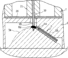
When carrying out puncture procedure, shown in Figure 10 A, the front end of body fluid collecting device Y is contacted with the skin surface Sk at puncture object position.At this moment, in order to promote the back taking-up body fluid that punctures, can make front end and the skin surface Sk friction of body fluid collecting device Y, or push this front end with strength.Certainly, also can utilize gap 65 and otch 38 in movable part 3, to form negative pressure.At this moment, under the situation of skin surface Sk protuberance, skin surface Sk contact with biosensor 5 (referring to Figure 10 B).At this moment because movable part 3 can be with respect to fixture 2 motion, therefore, can make according to the protuberance amount of skin surface Sk movable part 3 with the tight state of contact of skin surface Sk under move upward.As a result,, make fixing body X can not hinder the protuberance of skin surface Sk, therefore can promote the taking-up of body fluid reliably because biosensor can not move fully.
In puncture procedure, exert pressure for puncture body 21 with pressing component 63, puncture body 21 can be moved downwards.Under the situation that pressing component 63 moves downwards, shown in Figure 10 B, pressing component 63 is interfered the upper end of puncture body 21, thereby exerts pressure for puncture body 21.This pressure will cut off between the flange 29 of puncture body 21 and the body 20, and puncture body 21 and body 20 are moved down independently of one another.Shown in Figure 10 C, puncture needle 28 passes the through hole 39 of movable part 3 after breaking through sealing member 26, shown in Figure 10 D, makes puncture needle 28 pass puncture object position.Like this, just make skin surface Sk ooze out body fluid.
As shown in figure 11, after the blood B1 that is taken out by skin surface Sk is trapped among the recess 5A of biosensor 5, be imported into stream 5B (referring to Fig. 8).In reagent layer 57 (referring to Fig. 6),, make glucose and electron transport substance generation redox reaction in the blood by the catalytic action of oxidoreductase.By redox reaction reduction electron transport substance.And voltage is applied to (referring to Fig. 5 and Fig. 6) on the reagent layer 57 by connecting pin 61 (referring to Fig. 8), the effect utmost point 55 and antielectrode 56, thus with the electron transport substance oxidation.On the other hand, in body fluid collecting device Y, measure the electronics that electron transport substance is discharged when oxidized, obtain the oxidation current value, calculate concentration of glucose in blood according to this oxidation current value again by connecting pin 61 (referring to Fig. 8).
The present invention is not limited only to the foregoing description.Technological thought of the present invention is applicable to that also all are used for the fixing body that punctures simultaneously and move and measure the concentration measurement apparatus of action.For example, technological thought of the present invention is applicable to utilizing enzyme reaction to measure the situation of cholesterol and lactic acid concn.In addition, technological thought of the present invention also is applicable to used fixing body in the sting device that moves that only punctures.
In addition, also can change the structure Design that puncture body is applied pressing force.For example, also fixing body and the moving body that is equivalent to pressing body can be made one, moving body is moved to skin surface, thus, the impact when utilizing fixing body and skin surface to collide is exerted pressure to puncture body, realizes puncture procedure.
And also need not utilize top cover that biosensor is installed on the movable part.
Claims (11)
1. a body fluid collecting device fixing body is characterized in that, is mounted in the fixing body of the front end of body fluid collecting device, comprising: maintenance has the fixture of the puncture body of puncture needle; Be used for obtaining the analyzer of information of the detected material of relevant body fluid; With the movable part that keeps described analyzer, wherein,
Described movable part by being installed in along the axially movable mode of described puncture needle on the described fixture, can move forward and backward with the front end of the relative together described body fluid collecting device of described analyzer.
2. body fluid collecting device fixing body as claimed in claim 1 is characterized in that, described deciding part is provided with the inner space that described puncture body is moved together, and described puncture needle is maintained in the described inner space under air-tight state.
3. body fluid collecting device fixing body as claimed in claim 2 is characterized in that described fixture has the opening that is used to make described inner space and external communications, and described inner space forms the air-tight state by the described opening of sealing member locking.
4. body fluid collecting device fixing body as claimed in claim 1, it is characterized in that, keep the top cover of described analyzer to be set on this movable part with described movable part, and by taking off described top cover, form and make described analyzer remain on state on the described movable part.
5. body fluid collecting device fixing body as claimed in claim 4, it is characterized in that, on described movable part, be provided with first maintaining body that is used to keep described analyzer, on described top cover, be provided with second maintaining body that is used to keep described analyzer, and the retentivity of the described analyzer of maintenance of described first maintaining body is greater than described second maintaining body.
6. body fluid collecting device fixing body as claimed in claim 5 is characterized in that described first maintaining body has a plurality of hook-shaped connection parts.
7. body fluid collecting device fixing body as claimed in claim 5 is characterized in that described analyzer has through hole, and described second maintaining body passes described through hole, and has
6. body fluid collecting device fixing body as claimed in claim 5 is characterized in that described first maintaining body has a plurality of hook-shaped connection parts.
7. body fluid collecting device fixing body as claimed in claim 5 is characterized in that described analyzer has through hole, and described second maintaining body passes described through hole, and has connection part, and described connection part has the part greater than described through hole diameter.
8. body fluid collecting device fixing body as claimed in claim 1, it is characterized in that, described analyzer has substrate, is formed at first electrode and second electrode on the described substrate, and the part of described first and second electrodes remains on the described movable part, and is outstanding to the side of described movable part.
9. body fluid collecting device fixing body as claimed in claim 1, it is characterized in that, described puncture body forms one by fragile flange portion and described fixture, and when applying load for described puncture body vertically, described puncture body can be with respect to described kinematic mount.
Applications Claiming Priority (2)
| Application Number | Priority Date | Filing Date | Title |
|---|---|---|---|
| JP2001237085 | 2001-08-03 | ||
| JP237085/2001 | 2001-08-03 |
Related Child Applications (1)
| Application Number | Title | Priority Date | Filing Date |
|---|---|---|---|
| CN2008101851693A Division CN101449978B (en) | 2001-08-03 | 2002-08-02 | Method of manufacturing installation body for body liquid sampling apparatus |
Publications (2)
| Publication Number | Publication Date |
|---|---|
| CN1538824A CN1538824A (en) | 2004-10-20 |
| CN100457032C true CN100457032C (en) | 2009-02-04 |
Family
ID=19068224
Family Applications (2)
| Application Number | Title | Priority Date | Filing Date |
|---|---|---|---|
| CNB028152182A Expired - Lifetime CN100457032C (en) | 2001-08-03 | 2002-08-02 | Installation body for body liquid sampling apparatus and method of manufacturing it |
| CN2008101851693A Expired - Lifetime CN101449978B (en) | 2001-08-03 | 2002-08-02 | Method of manufacturing installation body for body liquid sampling apparatus |
Family Applications After (1)
| Application Number | Title | Priority Date | Filing Date |
|---|---|---|---|
| CN2008101851693A Expired - Lifetime CN101449978B (en) | 2001-08-03 | 2002-08-02 | Method of manufacturing installation body for body liquid sampling apparatus |
Country Status (5)
| Country | Link |
|---|---|
| US (1) | US8323212B2 (en) |
| EP (1) | EP1413249B1 (en) |
| JP (1) | JP4324469B2 (en) |
| CN (2) | CN100457032C (en) |
| WO (1) | WO2003013356A1 (en) |
Families Citing this family (65)
| Publication number | Priority date | Publication date | Assignee | Title |
|---|---|---|---|---|
| US6036924A (en) | 1997-12-04 | 2000-03-14 | Hewlett-Packard Company | Cassette of lancet cartridges for sampling blood |
| US6391005B1 (en) | 1998-03-30 | 2002-05-21 | Agilent Technologies, Inc. | Apparatus and method for penetration with shaft having a sensor for sensing penetration depth |
| US8641644B2 (en) | 2000-11-21 | 2014-02-04 | Sanofi-Aventis Deutschland Gmbh | Blood testing apparatus having a rotatable cartridge with multiple lancing elements and testing means |
| DE60234598D1 (en) | 2001-06-12 | 2010-01-14 | Pelikan Technologies Inc | SELF-OPTIMIZING LANZET DEVICE WITH ADAPTANT FOR TEMPORAL FLUCTUATIONS OF SKIN PROPERTIES |
| US7025774B2 (en) | 2001-06-12 | 2006-04-11 | Pelikan Technologies, Inc. | Tissue penetration device |
| US9795747B2 (en) | 2010-06-02 | 2017-10-24 | Sanofi-Aventis Deutschland Gmbh | Methods and apparatus for lancet actuation |
| DE60234597D1 (en) | 2001-06-12 | 2010-01-14 | Pelikan Technologies Inc | DEVICE AND METHOD FOR REMOVING BLOOD SAMPLES |
| ES2357887T3 (en) | 2001-06-12 | 2011-05-03 | Pelikan Technologies Inc. | APPARATUS FOR IMPROVING THE BLOOD OBTAINING SUCCESS RATE FROM A CAPILLARY PUNCTURE. |
| US8337419B2 (en) | 2002-04-19 | 2012-12-25 | Sanofi-Aventis Deutschland Gmbh | Tissue penetration device |
| AU2002315180A1 (en) | 2001-06-12 | 2002-12-23 | Pelikan Technologies, Inc. | Electric lancet actuator |
| US9226699B2 (en) | 2002-04-19 | 2016-01-05 | Sanofi-Aventis Deutschland Gmbh | Body fluid sampling module with a continuous compression tissue interface surface |
| US9427532B2 (en) | 2001-06-12 | 2016-08-30 | Sanofi-Aventis Deutschland Gmbh | Tissue penetration device |
| US7981056B2 (en) | 2002-04-19 | 2011-07-19 | Pelikan Technologies, Inc. | Methods and apparatus for lancet actuation |
| AU2002348683A1 (en) | 2001-06-12 | 2002-12-23 | Pelikan Technologies, Inc. | Method and apparatus for lancet launching device integrated onto a blood-sampling cartridge |
| DE10142232B4 (en) * | 2001-08-29 | 2021-04-29 | Roche Diabetes Care Gmbh | Process for the production of an analytical aid with a lancet and test element |
| US9314194B2 (en) | 2002-04-19 | 2016-04-19 | Sanofi-Aventis Deutschland Gmbh | Tissue penetration device |
| US7371247B2 (en) | 2002-04-19 | 2008-05-13 | Pelikan Technologies, Inc | Method and apparatus for penetrating tissue |
| US8784335B2 (en) | 2002-04-19 | 2014-07-22 | Sanofi-Aventis Deutschland Gmbh | Body fluid sampling device with a capacitive sensor |
| US7226461B2 (en) | 2002-04-19 | 2007-06-05 | Pelikan Technologies, Inc. | Method and apparatus for a multi-use body fluid sampling device with sterility barrier release |
| US8372016B2 (en) | 2002-04-19 | 2013-02-12 | Sanofi-Aventis Deutschland Gmbh | Method and apparatus for body fluid sampling and analyte sensing |
| US7175642B2 (en) | 2002-04-19 | 2007-02-13 | Pelikan Technologies, Inc. | Methods and apparatus for lancet actuation |
| US7297122B2 (en) | 2002-04-19 | 2007-11-20 | Pelikan Technologies, Inc. | Method and apparatus for penetrating tissue |
| US7291117B2 (en) | 2002-04-19 | 2007-11-06 | Pelikan Technologies, Inc. | Method and apparatus for penetrating tissue |
| US8267870B2 (en) | 2002-04-19 | 2012-09-18 | Sanofi-Aventis Deutschland Gmbh | Method and apparatus for body fluid sampling with hybrid actuation |
| US7901362B2 (en) | 2002-04-19 | 2011-03-08 | Pelikan Technologies, Inc. | Method and apparatus for penetrating tissue |
| US9795334B2 (en) | 2002-04-19 | 2017-10-24 | Sanofi-Aventis Deutschland Gmbh | Method and apparatus for penetrating tissue |
| US7491178B2 (en) | 2002-04-19 | 2009-02-17 | Pelikan Technologies, Inc. | Method and apparatus for penetrating tissue |
| US8702624B2 (en) | 2006-09-29 | 2014-04-22 | Sanofi-Aventis Deutschland Gmbh | Analyte measurement device with a single shot actuator |
| US7674232B2 (en) | 2002-04-19 | 2010-03-09 | Pelikan Technologies, Inc. | Method and apparatus for penetrating tissue |
| US7547287B2 (en) | 2002-04-19 | 2009-06-16 | Pelikan Technologies, Inc. | Method and apparatus for penetrating tissue |
| US7717863B2 (en) | 2002-04-19 | 2010-05-18 | Pelikan Technologies, Inc. | Method and apparatus for penetrating tissue |
| US7331931B2 (en) | 2002-04-19 | 2008-02-19 | Pelikan Technologies, Inc. | Method and apparatus for penetrating tissue |
| US7229458B2 (en) | 2002-04-19 | 2007-06-12 | Pelikan Technologies, Inc. | Method and apparatus for penetrating tissue |
| US8360992B2 (en) | 2002-04-19 | 2013-01-29 | Sanofi-Aventis Deutschland Gmbh | Method and apparatus for penetrating tissue |
| US7232451B2 (en) | 2002-04-19 | 2007-06-19 | Pelikan Technologies, Inc. | Method and apparatus for penetrating tissue |
| US7909778B2 (en) | 2002-04-19 | 2011-03-22 | Pelikan Technologies, Inc. | Method and apparatus for penetrating tissue |
| US8579831B2 (en) | 2002-04-19 | 2013-11-12 | Sanofi-Aventis Deutschland Gmbh | Method and apparatus for penetrating tissue |
| US7648468B2 (en) | 2002-04-19 | 2010-01-19 | Pelikon Technologies, Inc. | Method and apparatus for penetrating tissue |
| US7892183B2 (en) | 2002-04-19 | 2011-02-22 | Pelikan Technologies, Inc. | Method and apparatus for body fluid sampling and analyte sensing |
| US8221334B2 (en) | 2002-04-19 | 2012-07-17 | Sanofi-Aventis Deutschland Gmbh | Method and apparatus for penetrating tissue |
| US9248267B2 (en) | 2002-04-19 | 2016-02-02 | Sanofi-Aventis Deustchland Gmbh | Tissue penetration device |
| US7976476B2 (en) | 2002-04-19 | 2011-07-12 | Pelikan Technologies, Inc. | Device and method for variable speed lancet |
| US8574895B2 (en) | 2002-12-30 | 2013-11-05 | Sanofi-Aventis Deutschland Gmbh | Method and apparatus using optical techniques to measure analyte levels |
| EP2238892A3 (en) | 2003-05-30 | 2011-02-09 | Pelikan Technologies Inc. | Apparatus for body fluid sampling |
| WO2004107964A2 (en) | 2003-06-06 | 2004-12-16 | Pelikan Technologies, Inc. | Blood harvesting device with electronic control |
| WO2006001797A1 (en) | 2004-06-14 | 2006-01-05 | Pelikan Technologies, Inc. | Low pain penetrating |
| US8282576B2 (en) | 2003-09-29 | 2012-10-09 | Sanofi-Aventis Deutschland Gmbh | Method and apparatus for an improved sample capture device |
| EP1680014A4 (en) | 2003-10-14 | 2009-01-21 | Pelikan Technologies Inc | Method and apparatus for a variable user interface |
| US7822454B1 (en) | 2005-01-03 | 2010-10-26 | Pelikan Technologies, Inc. | Fluid sampling device with improved analyte detecting member configuration |
| WO2005065414A2 (en) | 2003-12-31 | 2005-07-21 | Pelikan Technologies, Inc. | Method and apparatus for improving fluidic flow and sample capture |
| WO2006011062A2 (en) | 2004-05-20 | 2006-02-02 | Albatros Technologies Gmbh & Co. Kg | Printable hydrogel for biosensors |
| US9775553B2 (en) | 2004-06-03 | 2017-10-03 | Sanofi-Aventis Deutschland Gmbh | Method and apparatus for a fluid sampling device |
| EP1765194A4 (en) | 2004-06-03 | 2010-09-29 | Pelikan Technologies Inc | Method and apparatus for a fluid sampling device |
| US8652831B2 (en) | 2004-12-30 | 2014-02-18 | Sanofi-Aventis Deutschland Gmbh | Method and apparatus for analyte measurement test time |
| CN102415888A (en) * | 2006-01-05 | 2012-04-18 | 松下电器产业株式会社 | Blood test apparatus |
| WO2007088875A1 (en) | 2006-02-01 | 2007-08-09 | Arkray, Inc. | Lancet |
| US8052618B2 (en) | 2006-10-15 | 2011-11-08 | Roche Diagnostics Operations, Inc. | Diagnostic test element and process for its production |
| JP5043863B2 (en) * | 2006-12-21 | 2012-10-10 | パナソニック株式会社 | Blood test equipment |
| WO2009126900A1 (en) | 2008-04-11 | 2009-10-15 | Pelikan Technologies, Inc. | Method and apparatus for analyte detecting device |
| US9375169B2 (en) | 2009-01-30 | 2016-06-28 | Sanofi-Aventis Deutschland Gmbh | Cam drive for managing disposable penetrating member actions with a single motor and motor and control system |
| EP2241252A1 (en) * | 2009-03-17 | 2010-10-20 | F. Hoffmann-La Roche AG | Testing device, in particular for blood sugar tests |
| KR101104391B1 (en) * | 2009-06-30 | 2012-01-16 | 주식회사 세라젬메디시스 | Sensor for measuring biomaterial used with measuring meter, and measuring device using this sensor |
| US8965476B2 (en) | 2010-04-16 | 2015-02-24 | Sanofi-Aventis Deutschland Gmbh | Tissue penetration device |
| USD816834S1 (en) * | 2017-04-28 | 2018-05-01 | Ucb Biopharma Sprl | Cap for injector |
| USD816835S1 (en) * | 2017-04-28 | 2018-05-01 | Ucb Biopharma Sprl | Cap for injector |
Citations (6)
| Publication number | Priority date | Publication date | Assignee | Title |
|---|---|---|---|---|
| JPH0595938A (en) * | 1991-07-09 | 1993-04-20 | Meitec Corp | Blood sampler |
| JPH0588503U (en) * | 1992-05-07 | 1993-12-03 | テルモ株式会社 | Puncture device for blood sampling |
| CN1125390A (en) * | 1993-05-13 | 1996-06-26 | 维达梅德有限公司 | Medical probe with stylets |
| JPH09108202A (en) * | 1995-10-16 | 1997-04-28 | Dainippon Printing Co Ltd | Body fluid sampling apparatus and body fluid analyzer using it |
| JP2000000231A (en) * | 1998-06-15 | 2000-01-07 | Kdk Corp | Lancet integrated type body fluid measuring instrument and attachment used by being attached to the body fluid measuring instrument |
| JP2000245717A (en) * | 1999-03-04 | 2000-09-12 | Terumo Corp | Puncture tool |
Family Cites Families (13)
| Publication number | Priority date | Publication date | Assignee | Title |
|---|---|---|---|---|
| SE465012B (en) | 1989-12-08 | 1991-07-15 | Freja Invest Kommanditbolag | CLEANING AID FOR ACHIEVEMENT OF POINTING OF BODY PARTS |
| HU219921B (en) | 1993-10-20 | 2001-09-28 | Ervin Lipscher | Device for making blood test, especially from fingers |
| US5636640A (en) | 1995-02-06 | 1997-06-10 | Volunteers For Medical Engineering | Liquid sampling and test apparatus |
| US6048352A (en) * | 1996-05-17 | 2000-04-11 | Mercury Diagnostics, Inc. | Disposable element for use in a body fluid sampling device |
| EP1579814A3 (en) * | 1996-05-17 | 2006-06-14 | Roche Diagnostics Operations, Inc. | Methods and apparatus for sampling and analyzing body fluid |
| US6027459A (en) * | 1996-12-06 | 2000-02-22 | Abbott Laboratories | Method and apparatus for obtaining blood for diagnostic tests |
| DE19830604C2 (en) * | 1998-07-09 | 2000-06-21 | November Ag Molekulare Medizin | Device for perforating skin |
| EP1139873B1 (en) * | 1999-01-04 | 2008-09-17 | Terumo Kabushiki Kaisha | Body fluid collecting and detecting lancet assembly |
| EP1238632B1 (en) * | 1999-12-13 | 2011-05-11 | ARKRAY, Inc. | Body fluid measuring apparatus with lancet and lancet holder used for the measuring apparatus |
| US6706159B2 (en) | 2000-03-02 | 2004-03-16 | Diabetes Diagnostics | Combined lancet and electrochemical analyte-testing apparatus |
| DE10030410C1 (en) * | 2000-06-21 | 2002-01-24 | Roche Diagnostics Gmbh | Blood lancet device for drawing blood for diagnostic purposes |
| US7025774B2 (en) * | 2001-06-12 | 2006-04-11 | Pelikan Technologies, Inc. | Tissue penetration device |
| US6766817B2 (en) * | 2001-07-25 | 2004-07-27 | Tubarc Technologies, Llc | Fluid conduction utilizing a reversible unsaturated siphon with tubarc porosity action |
-
2002
- 2002-08-02 CN CNB028152182A patent/CN100457032C/en not_active Expired - Lifetime
- 2002-08-02 WO PCT/JP2002/007934 patent/WO2003013356A1/en active Application Filing
- 2002-08-02 US US10/485,594 patent/US8323212B2/en not_active Expired - Lifetime
- 2002-08-02 EP EP02755801.4A patent/EP1413249B1/en not_active Expired - Lifetime
- 2002-08-02 CN CN2008101851693A patent/CN101449978B/en not_active Expired - Lifetime
- 2002-08-02 JP JP2003518374A patent/JP4324469B2/en not_active Expired - Fee Related
Patent Citations (6)
| Publication number | Priority date | Publication date | Assignee | Title |
|---|---|---|---|---|
| JPH0595938A (en) * | 1991-07-09 | 1993-04-20 | Meitec Corp | Blood sampler |
| JPH0588503U (en) * | 1992-05-07 | 1993-12-03 | テルモ株式会社 | Puncture device for blood sampling |
| CN1125390A (en) * | 1993-05-13 | 1996-06-26 | 维达梅德有限公司 | Medical probe with stylets |
| JPH09108202A (en) * | 1995-10-16 | 1997-04-28 | Dainippon Printing Co Ltd | Body fluid sampling apparatus and body fluid analyzer using it |
| JP2000000231A (en) * | 1998-06-15 | 2000-01-07 | Kdk Corp | Lancet integrated type body fluid measuring instrument and attachment used by being attached to the body fluid measuring instrument |
| JP2000245717A (en) * | 1999-03-04 | 2000-09-12 | Terumo Corp | Puncture tool |
Also Published As
| Publication number | Publication date |
|---|---|
| US8323212B2 (en) | 2012-12-04 |
| EP1413249A4 (en) | 2009-07-22 |
| JP4324469B2 (en) | 2009-09-02 |
| WO2003013356A1 (en) | 2003-02-20 |
| EP1413249A1 (en) | 2004-04-28 |
| CN101449978B (en) | 2010-12-01 |
| US20040209350A1 (en) | 2004-10-21 |
| JPWO2003013356A1 (en) | 2004-11-25 |
| CN1538824A (en) | 2004-10-20 |
| CN101449978A (en) | 2009-06-10 |
| EP1413249B1 (en) | 2013-10-09 |
Similar Documents
| Publication | Publication Date | Title |
|---|---|---|
| CN100457032C (en) | Installation body for body liquid sampling apparatus and method of manufacturing it | |
| JP4214274B2 (en) | Puncture element integrated body | |
| US8343074B2 (en) | Fluid handling devices | |
| EP1960771B1 (en) | Sensors | |
| CA2529651C (en) | Test strip with flared sample receiving chamber | |
| EP2568281B1 (en) | Disposable sensor for electrochemical detection of hemoglobin | |
| US8650751B2 (en) | Methods of making small volume in vitro analyte sensors | |
| JP5068825B2 (en) | Biosensor | |
| WO1999045387A3 (en) | Electrochemical analyte sensor | |
| US9678034B2 (en) | Analyte sensors and systems including retention tab and methods of manufacturing same | |
| AU2358299A (en) | Process for the production of analytical devices | |
| JPH11183423A (en) | Sensor and sensor set | |
| JP3890417B2 (en) | Biosensor having protective film capable of bonding and peeling | |
| KR20180006968A (en) | Method and test element for electrochemically detecting at least one analyte in a sample of a body fluid | |
| US20150346142A1 (en) | Determination of the real electrochemical surface areas of screen printed electrodes | |
| WO2002014535A2 (en) | Electrochemical strip test for small volumes | |
| JP4665135B2 (en) | Biosensor manufacturing method | |
| US20100000861A1 (en) | Packaging system for testing devices | |
| JP4649594B2 (en) | Biosensor and manufacturing method thereof | |
| JP4670013B2 (en) | Biosensor and manufacturing method thereof |
Legal Events
| Date | Code | Title | Description |
|---|---|---|---|
| C06 | Publication | ||
| PB01 | Publication | ||
| C10 | Entry into substantive examination | ||
| SE01 | Entry into force of request for substantive examination | ||
| C14 | Grant of patent or utility model | ||
| GR01 | Patent grant | ||
| CX01 | Expiry of patent term |
Granted publication date: 20090204 |
|
| CX01 | Expiry of patent term |