CN100369722C - Apparatus and method for calling mobile robot - Google Patents
Apparatus and method for calling mobile robot Download PDFInfo
- Publication number
- CN100369722C CN100369722C CNB2005100531393A CN200510053139A CN100369722C CN 100369722 C CN100369722 C CN 100369722C CN B2005100531393 A CNB2005100531393 A CN B2005100531393A CN 200510053139 A CN200510053139 A CN 200510053139A CN 100369722 C CN100369722 C CN 100369722C
- Authority
- CN
- China
- Prior art keywords
- mobile robot
- signal
- remote controller
- ultrasonic
- infrared
- Prior art date
- Legal status (The legal status is an assumption and is not a legal conclusion. Google has not performed a legal analysis and makes no representation as to the accuracy of the status listed.)
- Expired - Fee Related
Links
- 238000000034 method Methods 0.000 title claims description 30
- 238000001514 detection method Methods 0.000 claims description 12
- 238000004364 calculation method Methods 0.000 claims description 6
- 230000007704 transition Effects 0.000 claims description 3
- 238000004140 cleaning Methods 0.000 description 10
- 238000010586 diagram Methods 0.000 description 10
- 230000004888 barrier function Effects 0.000 description 6
- 230000008569 process Effects 0.000 description 5
- 230000008901 benefit Effects 0.000 description 3
- 238000005516 engineering process Methods 0.000 description 3
- 241001212149 Cathetus Species 0.000 description 1
- NBIIXXVUZAFLBC-UHFFFAOYSA-N Phosphoric acid Chemical compound OP(O)(O)=O NBIIXXVUZAFLBC-UHFFFAOYSA-N 0.000 description 1
- 230000008859 change Effects 0.000 description 1
- 238000006243 chemical reaction Methods 0.000 description 1
- 238000006073 displacement reaction Methods 0.000 description 1
- 239000000428 dust Substances 0.000 description 1
- 230000008676 import Effects 0.000 description 1
- 230000006698 induction Effects 0.000 description 1
- 238000004519 manufacturing process Methods 0.000 description 1
- 230000004048 modification Effects 0.000 description 1
- 238000012986 modification Methods 0.000 description 1
- 238000003860 storage Methods 0.000 description 1
- 239000000126 substance Substances 0.000 description 1
Images


Classifications
-
- G—PHYSICS
- G05—CONTROLLING; REGULATING
- G05D—SYSTEMS FOR CONTROLLING OR REGULATING NON-ELECTRIC VARIABLES
- G05D1/00—Control of position, course, altitude or attitude of land, water, air or space vehicles, e.g. using automatic pilots
- G05D1/02—Control of position or course in two dimensions
- G05D1/021—Control of position or course in two dimensions specially adapted to land vehicles
- G05D1/0231—Control of position or course in two dimensions specially adapted to land vehicles using optical position detecting means
- G05D1/0242—Control of position or course in two dimensions specially adapted to land vehicles using optical position detecting means using non-visible light signals, e.g. IR or UV signals
-
- A—HUMAN NECESSITIES
- A47—FURNITURE; DOMESTIC ARTICLES OR APPLIANCES; COFFEE MILLS; SPICE MILLS; SUCTION CLEANERS IN GENERAL
- A47L—DOMESTIC WASHING OR CLEANING; SUCTION CLEANERS IN GENERAL
- A47L9/00—Details or accessories of suction cleaners, e.g. mechanical means for controlling the suction or for effecting pulsating action; Storing devices specially adapted to suction cleaners or parts thereof; Carrying-vehicles specially adapted for suction cleaners
- A47L9/28—Installation of the electric equipment, e.g. adaptation or attachment to the suction cleaner; Controlling suction cleaners by electric means
-
- A—HUMAN NECESSITIES
- A47—FURNITURE; DOMESTIC ARTICLES OR APPLIANCES; COFFEE MILLS; SPICE MILLS; SUCTION CLEANERS IN GENERAL
- A47L—DOMESTIC WASHING OR CLEANING; SUCTION CLEANERS IN GENERAL
- A47L11/00—Machines for cleaning floors, carpets, furniture, walls, or wall coverings
-
- G—PHYSICS
- G05—CONTROLLING; REGULATING
- G05D—SYSTEMS FOR CONTROLLING OR REGULATING NON-ELECTRIC VARIABLES
- G05D1/00—Control of position, course, altitude or attitude of land, water, air or space vehicles, e.g. using automatic pilots
- G05D1/0011—Control of position, course, altitude or attitude of land, water, air or space vehicles, e.g. using automatic pilots associated with a remote control arrangement
- G05D1/0022—Control of position, course, altitude or attitude of land, water, air or space vehicles, e.g. using automatic pilots associated with a remote control arrangement characterised by the communication link
Landscapes
- Engineering & Computer Science (AREA)
- Physics & Mathematics (AREA)
- General Physics & Mathematics (AREA)
- Automation & Control Theory (AREA)
- Aviation & Aerospace Engineering (AREA)
- Radar, Positioning & Navigation (AREA)
- Remote Sensing (AREA)
- Electromagnetism (AREA)
- Mechanical Engineering (AREA)
- Control Of Position, Course, Altitude, Or Attitude Of Moving Bodies (AREA)
- Electric Vacuum Cleaner (AREA)
- Manipulator (AREA)
- Selective Calling Equipment (AREA)
- Measurement Of Velocity Or Position Using Acoustic Or Ultrasonic Waves (AREA)
Abstract
An apparatus for calling a mobile robot (200) includes a generator (101,102) installed at a remote controller (100), and generating an RF signal and infrared signal for calling a mobile robot (200) when a call signal is inputted by a user; and a controller (202) installed at the mobile robot (200), calculating a direction of the remote controller (100) based on a position of an infrared ray receiver that receives the infrared signal when an RF signal is received, rotating the mobile robot (200) in the calculated direction, and then making the mobile robot (200) to go straight ahead.
Description
Technical field
The present invention relates to the mobile robot, and more specifically, relate to a kind of apparatus and method that are used for calling mobile robot.
Background technology
Generally speaking, the mobile robot is the equipment that is used for the automated cleaning zone, and it is drawn from the floor when move own this lining, room (for example living room or the like) in the house such as the foreign substance of dust and handles without the user.
In cleaning, robot cleaner is by range sensor identification itself and barrier, such as furniture, the distance of the wall in public product or the cleaning area, and optionally control the motor of the revolver that is used to rotate it and be used to rotate the motor of its right side wheel according to the distance of identification, change its direction whereby and sweep the cleaning area automatically.Here, robot cleaner is carried out clean operation when advancing in the cleaning area by the cartographic information that is stored in internal storage unit.
For example, robot cleaner comprises gyro sensor, and it is used to respond to the direction of robot cleaner; Encoder, it is used for determining displacement by the number of times of induction robot cleaner wheel turns; Sonac, it is used to respond to robot cleaner, the distance between the target; And infrared ray sensor, it is used to respond to barrier; With other many sensors.
Yet the shortcoming that the existing robots cleaner has is, because the sensor that many high prices have been installed to be carrying out cleaning by accurately advancing along default cleaning path, its internal structure is complicated and increased manufacturing cost.
In order to make great efforts to address this problem, developed robot cleaner and come by advancing along cleaning path arbitrarily with random fashion, thus the cleaning of execution.
Travelling equipment according to the robot cleaner of prior art will be described now.
Fig. 1 is the block diagram that has shown according to the structure of the travelling equipment of the robot cleaner of prior art.
As shown in Figure 1, the travelling equipment of existing robot cleaner comprises: obstacle detection unit 1, and it is used for based on detecting barrier and generation obstacle detection signal when robot cleaner at the specific region cathetus buckles that produces when conflict with barrier that advances; Controller, the conduct that it is used for stopping according to the obstacle detection signal that obstacle detection unit 1 produces robot cleaner produces angle at random randomly, and generation is used for the basis control signal of angular turn robot cleaner at random; Left side motor drive unit 3, it is used for according to the control signal of controller 2 to determine the left motor (ML) 5 of speed rotary machine people cleaner; With right motor drive unit 4, it is used for according to the control signal of controller 2 to determine the right motor (MR) 6 of speed rotary machine people cleaner.
Fig. 2 is the flow chart according to the method for advancing that is used for robot cleaner of prior art.
At first, when the user imports the cleaning command signal (step S1), controller 2 produces control signal so that the velocity of rotation of left motor 5 and right motor 6 equates, so that make the robot cleaner straight ahead, and output a control signal to left motor drive unit 3 and right motor drive unit 4 (step S2) simultaneously.
Left side motor drive unit 3 rotates left motor 5 according to the control signal of controller.At this moment, right motor drive unit 4 rotates right motor 6 according to the control signal of controller 2.That is, because a left side and right motor 5 and 6 rotate the robot cleaner straight ahead synchronously.
Obstacle detection unit detects barrier based on the buckles that produces when robot cleaner conflicts with barrier, produce the obstacle detection signal, and provide the obstacle detection signal to controller 2 (step S3).If do not produce the obstacle detection signal, robot cleaner continues to carry out clean operation.
Left side motor drive unit 3 rotates left motor 5 according to the control signal of controller 2, and right motor drive unit 4 rotates right motor 6 according to the control signal of controller.In other words, the velocity of rotation by differently controlling left motor 5 and the velocity of rotation of right motor 6, the direction of robot cleaner can be changed and be arbitrarily angled (step S5).
After this, when robot cleaner turned at random angle, controller allowed robot cleaner straight ahead (step S6).When the clean operation of robot cleaner was finished, controller stopped clean operation (step S7).If the clean operation of robot cleaner is not finished, controller allows robot cleaner repeatedly to carry out clean operation.
If when this robot cleaner is being carried out clean operation, the user wants to move this robot cleaner to certain location, this user should stop the operation of this robot cleaner, picks up this robot cleaner then in person it is moved to this certain location.That is to say that the problem that this existing robots cleaner has is that the user will pick up this robot cleaner in person, and it is moved to different clean space or robot cleaner warehouse.
U.S. Patent No. 5,440,216 and 5,646,494 also disclose a kind of robot cleaner.
Summary of the invention
Therefore, the purpose of this invention is to provide a kind of apparatus and method that are used for calling mobile robot, when the user when certain location is called out this mobile robot, these apparatus and method can make the mobile robot, move to certain location such as robot cleaner oneself, make this user not need to pick up in person this mobile robot it is moved to the position of wanting, thereby strengthened user convenience.
In order to realize the advantage of these and other, and according to purpose of the present invention, as describing particularly and widely herein, a kind of device that is used for calling mobile robot is provided, it comprises: be installed in the generator on the remote controller, it produces the RF signal and the infrared signal that are used for calling mobile robot when by user's incoming call signal the time; With the controller that is installed on this mobile robot, it is when explaining the RF signal, calculate the direction of this remote controller based on the position of the infrared receiver that receives this infrared signal, rotate this mobile robot, make this mobile robot's straight ahead then with the direction of calculating.
In order to realize above-described purpose, a kind of device that is used for calling mobile robot also is provided, comprising: be installed in the generator on the remote controller, it is from user's receiving calling signal, and generation is used for the RF signal and the ultrasonic signal of calling mobile robot; With the controller that is installed on this mobile robot, it is when receiving the RF signal, calculate the direction of this remote controller based on the position of the ultrasonic receiver that has received ultrasonic signal, the time that arrives ultrasonic receiver based on ultrasonic signal is calculated the distance between this remote controller and this mobile robot, direction with this calculating is rotated the mobile robot, makes this mobile robot's straight ahead calculated distance then.
In order to realize above-described purpose, a kind of device that is used for calling mobile robot also is provided, it comprises: be installed in the RF generator on the remote controller, and it produces the RF signal that is used for calling mobile robot when by user's incoming call signal the time; Be installed in the infrared generator on this remote controller, and it produces the infrared signal that is used to indicate the remote controller direction in the time of this call signal of input; Be installed in the RF receiver on this mobile robot, and it receives the RF signal that produces from the RF generator; Be installed in a plurality of infrared receivers on the mobile robot, and it receives the infrared signal that produces from this infrared generator; With the controller that is installed on the mobile robot, it is when the RF receiver receives the RF signal, discern the direction of remote controller based on the position that among a plurality of infrared receivers, has received the infrared receiver of this infrared signal, rotate this mobile robot with the direction of this identification, and make mobile robot's straight ahead.
In order to realize above-described purpose, a kind of device that is used for calling mobile robot also is provided, comprising: be installed in the RF generator on the remote controller, and it produces the RF signal that is used for calling mobile robot when call signal is imported by the user; Be installed in the supersonic generator on the remote controller, and it produces and is used in reference to the ultrasonic signal that is shown in the distance between mobile robot and the remote controller in the time of the incoming call signal; Be installed in the RF receiver on this mobile robot, and it receives the RF signal that produces from this RF generator; Be installed in a plurality of ultrasonic receivers on this mobile robot, and it receives the ultrasonic signal that produces from this supersonic generator; With the controller that is installed on this mobile robot, it is when this RF receiver receives the RF signal, based on the position that among a plurality of ultrasonic receivers, has received the ultrasonic receiver of ultrasonic signal, calculate the direction of this remote controller, and the distance between this mobile robot and this remote controller, based on the direction and the distance value of this calculating this mobile robot is moved to remote controller.
In order to realize above-described purpose, a kind of method that is used for calling mobile robot also is provided, it comprises: wherein when call signal is transfused to remote controller, be used for the RF signal of calling mobile robot and the step of infrared signal via this remote controller generation; Wherein when this RF signal is received by this mobile robot, with this mobile robot's mode transitions is call model, and calculates the step of the direction of this remote controller based on the position that has received the infrared receiver of infrared signal among a plurality of infrared receivers that are installed on this mobile robot; Wherein rotate this mobile robot's front side, allow the step of this mobile robot's straight ahead then with the direction of calculating.
In order to realize above-described purpose, a kind of method that is used for calling mobile robot also is provided, comprise: wherein when call signal is transfused to remote controller, be used for the RF signal of calling mobile robot and the step of ultrasonic signal via this remote controller generation simultaneously; Wherein when this RF signal is received by this mobile robot's RF receiver, this mobile robot's operator scheme is changed into call model, calculate the step of the direction of this remote controller then based on the position that among a plurality of ultrasonic receivers that are installed on the mobile robot, has received the ultrasonic receiver of ultrasonic signal; Wherein the time that arrives this ultrasonic receiver based on ultrasonic signal is calculated the step of the distance between this remote controller and this mobile robot; Wherein rotate the step of this mobile robot's front side with the direction of this calculating; And the step that wherein allows this mobile robot's straight ahead calculated distance value.
From the detailed description below in conjunction with accompanying drawing, above-mentioned purpose, characteristics, mode and advantage with other of the present invention will become more high-visible.
Description of drawings
Accompanying drawing comprises in order further to understand the present invention, and is included into a part that constitutes this specification in this specification, and these accompanying drawings show embodiments of the invention, and are used for this specification principle of the present invention being described.
In the accompanying drawings:
Fig. 1 is the block diagram that illustrates according to the apparatus structure of advancing that is used for robot cleaner of existing technology;
Fig. 2 is the flow chart according to the method for advancing that is used for robot cleaner of prior art;
Fig. 3 is the block diagram that illustrates according to the device that is used for calling mobile robot of first embodiment of the invention;
Fig. 4 is the schematic diagram that is installed in a plurality of infrared receivers on the mobile robot that illustrates according to first embodiment of the invention;
Fig. 5 illustrates to send RF signal and the infrared signal schematic diagram to mobile robot's process according to first embodiment of the invention from remote controller;
Fig. 6 is the flow chart according to the method that is used for calling mobile robot of first embodiment of the invention;
Fig. 7 is the explanatory view that illustrates according to processing procedure of the present invention, wherein rotates mobile robot's front side with the direction of remote controller, allows mobile robot's straight ahead then;
Fig. 8 is the block diagram that illustrates according to the apparatus structure that is used for calling mobile robot of the second embodiment of the present invention; With
Fig. 9 is the flow chart according to the method that is used for calling mobile robot of second embodiment of the invention.
The specific embodiment
Referring now to the apparatus and method that are used for calling mobile robot of accompanying drawing description according to the preferred embodiment of the present invention, when the user when certain location is called out this mobile robot, these apparatus and method can make the mobile robot, move to certain location such as robot cleaner oneself, make the user not need to pick up in person this mobile robot it is moved to the position of wanting, thereby strengthen user convenience.
Fig. 3 is the block diagram that illustrates according to the device that is used for calling mobile robot of first embodiment of the invention.
As shown in Figure 3, the device that is used for calling mobile robot according to first embodiment of the invention comprises: be installed in the RF generator 101 on the remote controller 100, and when it is imported by the user when call signal, produce the RF signal that is used for calling mobile robot 200; Be installed in the infrared generator 102 on this remote controller 100, and it is in the time of the incoming call signal, produces the infrared signal of the direction that is used to indicate remote controller 100; Be installed in the RF receiver 201 on this mobile robot 200, and it receives the RF signal that produces from RF generator 101; Be installed in a plurality of infrared receiver 203-1~203-N on the mobile robot 200, and it receives the infrared signal that produces from infrared generator 102; With the controller 202 that is installed on the mobile robot 200, when it receives the RF signal when RF receiver 201, discern the direction of remote controller 100 based on the position that among a plurality of infrared receiver 203-1~203-N, has received the infrared receiver of infrared signal, move mobile robot 200 with the direction of remote controller 100.
The position that is installed in a plurality of infrared receiver 203-1~203-N on the mobile robot is described below with reference to Fig. 4.
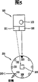
Fig. 4 is the schematic diagram that is installed in a plurality of infrared receivers on the mobile robot that illustrates according to first embodiment of the invention.
As shown in Figure 4, a plurality of infrared receiver 203-1~203-N preferably are installed on mobile robot 200 the outer circumferential surface with the interval of determining based on mobile robot 200 front side, wherein the first infrared receiver IR0 is preferably mounted on mobile robot 200 the front side, so that benchmark angle (for example, 0 °) is set.
Fig. 5 illustrates to send RF signal and the infrared signal schematic diagram to mobile robot's process according to first embodiment of the invention from remote controller.
As shown in Figure 5, the user towards this mobile robot 200, and presses the call button 103 that is installed on the remote controller 100 with remote controller 100.Then, the direction with mobile robot 200 sends RF signal and infrared signal.At this moment, when the direction of remote controller 100 and mobile robot's 200 direction was corresponding mutually, this infrared signal was received by the outer line receiver IR3 of quatre.
Describe according to the work that is used for the device of calling mobile robot of the present invention below with reference to Fig. 4 to 6.
Fig. 6 is the flow chart according to the method that is used for calling mobile robot of first embodiment of the invention.
At first, when the user selects the call button 103 of remote controller 100 (step S11), be installed in RF generator 101 on the remote controller 100 and produce and be used for the RF signal of calling mobile robot 200, and the RF signal that sends this generation is to the RF receiver 201 that is installed among the mobile robot 200.
When this user selects the call button 103 of remote controller 100 (step S11), the infrared generator 102 that is installed in the remote controller 100 produces the infrared signal that is used to notify its direction, and sends the infrared signal (step S12) that produces with mobile robot 200 direction.Here, the direction of infrared generator 102 refers to the direction of remote controller 100.
After this, the RF receiver 201 that is installed among the mobile robot 200 receives the RF signal that sends from RF generator 101.At this moment, be positioned at and the infrared receiver on the identical direction of the infrared generator 102 among a plurality of infrared receiver 203-1~203-N that are installed on the mobile robot 200 (for example, quatre outer line receiver IR3) receives the infrared signal that sends from this infrared generator 102.
Then, when RF receiver 201 received the RF signal, controller 202 conversion mobile robots' 200 operator scheme was call model (step S14).In addition, controller 202 calculates the direction (step S15) of remote controller 100 based on the position of the infrared receiver that has received infrared signal among a plurality of infrared signal 203-1~203-N (for example, the outer line receiver IR3 of quatre).Here, controller 202 can comprise the memory cell (not shown) that is used to store the predeterminated position number, this predeterminated position number is used to differentiate the position of a plurality of infrared receiver 203-1~203-N, and this controller 202 also determines to have received the position of the infrared receiver of infrared signal based on the predeterminated position number of infrared receiver.
For example, suppose that with the first infrared receiver IR0 on the front side that is installed in mobile robot 200 be benchmark, the outer line receiver IR3 of quatre that installs with 135 ° directions receives infrared signal, controller 202 can be discerned 45 ° of directions that remote controller 100 is positioned at this mobile robot's 200 front side, and this is because the angle between the line receiver IR3 is 135 ° outside the first infrared receiver IR0 and quatre.Here, in order to calculate the direction of remote controller 100, preferably, the Position Number of first infrared receiver is 0, the Position Number of second infrared receiver is set to 1, the Position Number of the 3rd infrared receiver is set to 2, and the Position Number of line receiver is set to 3 outside the quatre, and the Position Number of N infrared receiver is set to N.
After this, controller 202 is based on the infrared receiver that has received infrared signal, promptly, the direction of remote controller 100 is calculated in the position of the outer line receiver IR3 of quatre, the front side of rotating this mobile robot 200 with the direction of remote controller 100 (for example, 135 °) (step S16), allow this mobile robot's straight ahead (step S17) then.
Be installed in controller 202 among the mobile robot 200 calculates remote controller 100 via the equation that illustrates below (1) direction (y):
y=2(π/n)×x --------(1)
Wherein " n " is mounted in the sum of a plurality of infrared receivers on the mobile robot 200, and " x " is the Position Number that has received the infrared receiver of the infrared signal that produces from infrared generator 102.
For example, if " n " is 8, and " x " be 0, and the direction of remote controller 100 (y) is 0 °, and if " n " be 8, and " x " be 3, the direction of remote controller 100 (y) is 135 °." x "=0 refers to the infrared receiver that receives infrared signal and is mounted in the first infrared receiver IR0 on mobile robot 200 the front side, and to refer to the infrared receiver that receives infrared signal be to be the outer line receiver IR3 of quatre that benchmark is installed with 135 ° direction with first infrared receiver in " x "=3.
Simultaneously, if this infrared signal is received by two or more infrared receivers, preferably, this intermediate point is calculated as the direction of remote controller 100.For example, when its Position Number is that infrared receiver IR2~IR4 of 3 to 5 is when receiving infrared signal simultaneously, preferably replace " x " value with median 4, and if its Position Number be that 5 to 8 infrared receiver receives infrared signal simultaneously, median 6 and 7 preferably replaces " x " to be worth.
Rotate mobile robot 200 front side and make the process of mobile robot 200 with the direction of remote controller 100 referring now to Fig. 7 description with the direction straight ahead of remote controller 100.
Fig. 7 is the explanatory view that illustrates according to processing procedure of the present invention, wherein rotates mobile robot's front side with the direction of remote controller, allows this mobile robot's straight ahead then.
As shown in Figure 7, suppose that a plurality of infrared receiver 203-1~203-N are installed on mobile robot's the outer circumferential surface at interval with definite, at adjacent infrared receiver (for example, first and second infrared receiver IR0 and the IR1) angle between is 45 °, and the infrared receiver that has received infrared signal is line receiver IR3 outside the quatre among a plurality of infrared receiver 203-1~203-N, controller 202 rotates 135 ° with mobile robot 200, makes this mobile robot's 200 straight ahead then.
In other words since first and quatre outside angle between line receiver IR0 and the IR3 be 135 °, when this mobile robot 200 was rotated 135 °, mobile robot's leading flank was to remote controller 100.Therefore, when mobile robot 200 is rotated 135 ° when allowing its straight ahead then, it will arrive the point that remote controller 100 exists.
When mobile robot 200 arrived the position that users want, the user disconnected call button 103 to stop mobile robot 200.For example, in the time of user's call establishment button 103, controller 202 moves mobile robot 200 with the direction of remote controller, and when the user disconnected call button 103, controller stopped mobile robot 200.Therefore, when moving when the user presses the call button that is installed on this remote controller 100 103, mobile robot 200 follows this user.In this case, the direction of remote controller 100 is preferably in the face of mobile robot 200.
Similarly, in existing technology, can easily move and rotate mobile robot 200 by a left side and the right motor of controlling mobile robot 200, so its detailed description is omitted.
By using supersonic generator and ultrasonic receiver, rather than use infrared generator 102 and a plurality of infrared receiver 203-1~203-N, can be by calculating the distance between remote controller 100 and mobile robot 200 and the direction of remote controller 100, when mobile robot 200 arrived remote controller 100, the device that is used for calling mobile robot can automatically stop mobile robot 200.
Fig. 8 is the block diagram that illustrates according to the apparatus structure that is used for calling mobile robot of second embodiment of the invention.
As shown in Figure 8, the device that is used for calling mobile robot according to second embodiment of the invention comprises: be installed in the RF generator 301 on the remote controller 300, and when it is imported by the user when call signal, produce the RF signal that is used for calling mobile robot 400; Be installed in the supersonic generator 302 on the remote controller 300, and it produces and is used in reference to the ultrasonic signal that is shown in distance between mobile robot 400 and the remote controller 300 in the time of the incoming call signal; Be installed in the RF receiver 401 on the mobile robot 400, and it receives the RF signal that produces by RF generator 301; Be installed in the ultrasonic receiver 403-1~403-N on the mobile robot 400, and it receives the ultrasonic signal that produces from supersonic generator 302; With the controller 402 that is installed on the mobile robot 400, it is when receiving the RF signal by RF receiver 401, based on the position that among a plurality of ultrasonic receiver 403-1~403-N, has received the ultrasonic receiver of ultrasonic signal, the direction of identification remote controller 300, the time that is received by ultrasonic receiver with ultrasonic signal is that benchmark calculates the distance between remote controller 300 and mobile robot 400, and moves mobile robot 400 to remote controller 300 based on the direction and the distance value of this calculating.
Here, preferably, this supersonic generator 302 and a plurality of ultrasonic receiver 403-1~403-N are installed on the mobile robot 400 in the mode identical with a plurality of infrared receiver 203-1~203-N with infrared generator 102 shown in Fig. 4,5 and 7.
Referring now to the operation of Fig. 9 description according to the device that is used for calling mobile robot of second embodiment of the invention.
Fig. 9 is the flow chart according to the method that is used for calling mobile robot of second embodiment of the invention.
At first, when the user selects the call button of remote controller 300 (step S21), RF generator 301 generations that are installed on the remote controller 300 are used for the RF signal of calling mobile robot 400, and send the RF receiver 401 (step S22) of the RF signal of this generation to mobile robot 400.
When the user selects the call button 103 of remote controller 300 (step S21), supersonic generator 302 produce be used to notify the direction of remote controller 300 and between remote controller 300 and mobile robot 400 ultrasonic signal of distance, and send the ultrasonic signal (step S22) of this generation with mobile robot 400 direction.
The RF receiver 401 that is installed on the mobile robot 400 receives the RF signal (step S23) that sends from RF generator 301.At this moment, the ultrasonic signal that is produced by supersonic generator 302 is received by the one or more ultrasonic receivers among a plurality of ultrasonic receiver 403-1~403-N.
When the RF signal was received by this RF receiver 401, controller 402 was call model (step S24) with this mobile robot's 400 mode transitions.In addition, controller 402 is based on the direction of the position calculation remote controller 300 of the ultrasonic receiver that has received ultrasonic signal.At this moment, controller 402 detects the time that ultrasonic signals arrive ultrasonic receivers, then based on the distance (step S25) of Time Calculation between mobile robot 400 and remote controller 300 of this detection.
After this, controller 402 makes this mobile robot's 400 straight ahead calculated distance values then with direction (direction of remote controller) the rotation mobile robot's 400 of calculating front side (step S26).That is, controller 402 by this mobile robot's 400 of control a left side and right motor, makes mobile robot's 400 straight ahead calculated distance values (step S27) then with the direction rotation mobile robot's 400 of calculating front side (step S26).Here, controller 402 can comprise the memory cell (not shown) that is used to store the Position Number that presets, this Position Number that presets is differentiated a plurality of ultrasonic receiver 403-1~403-N, and this controller 402 is based on the definite position that has received the ultrasonic receiver of ultrasonic signal of the Position Number of ultrasonic receiver.
The process of calculating remote controller 300 directions is identical with first embodiment of the invention, and therefore, its description is omitted.
The time that now detailed description is used for ultrasonic signal arrival ultrasonic receiver is the process that benchmark calculates distance between remote controller 300 and mobile robot 400.
At first, based on the time point that produces the RF signal as benchmark, after the supersonic generator 302 from remote controller 300 has produced ultrasonic signal, controller 402 detects the time that these ultrasonic signals arrive one or more ultrasonic receivers, and based on the distance of Time Calculation between mobile robot 400 and remote controller 300 of this detection.
For example, when a ultrasonic receiver (for example, when 403-1) receiving ultrasonic signal, controller 402 arrives the time of ultrasonic receiver based on ultrasonic signal, acquisition at the ultrasonic receiver that has received ultrasonic signal (for example, 403-1) and the distance between the remote controller 300, and add the distance value of this mobile robot's 400 radius, thereby accurately calculate the actual range between mobile robot 400 and remote controller 300 to this acquisition.
If this ultrasonic signal is received by two or more ultrasonic receivers, based on when ultrasonic signal arrives the distance of Time Calculation between each ultrasonic receiver and remote controller 300 of two or more ultrasonic receivers to controller 402, and then, by triangulation, calculate the actual range between mobile robot 400 and remote controller 300 based on each calculated distance value.Distance between mobile robot 400 and remote controller 300 can be calculated by the equation (2) that illustrates below:
S=340[m/sec]×(T1-T2)------(2)
Wherein, 340[m/sec] be the velocity of sound, T1 is the received time of ultrasonic signal, and T2 is the time that is produced by ultrasonic signal after producing at the RF signal.
The device that is used for calling mobile robot can be applied to various mobile devices and mobile robot.
As described up to now, has a lot of advantages according to the apparatus and method that are used for calling mobile robot of the present invention.
That is to say that for example, as user from the certain location calling mobile robot time, this mobile robot can oneself move to certain location, thereby strengthens user convenience.For example, by moving the mobile robot via remote controller, to the position of wanting (clean space or mobile robot warehouse), the user does not need to pick up troublesomely this mobile robot and moves it to the position of wanting such as robot cleaner.
Because under the situation that does not break away from spirit of the present invention and substantive characteristics, it can be embodied in various ways, should be appreciated that unless stated otherwise, the above embodiments be can't help the details of any aforementioned description and are limited, but understood widely in the spirit and scope that should in additional claim, define, and therefore, all are in the claim scope, or the modifications and changes in the equivalent of scope all are intended to by additional claim included.
Claims (16)
1. device that is used for calling mobile robot, it comprises:
The RF generator, it is installed on the remote controller, and produces the RF signal that is used for calling mobile robot when by user's incoming call signal the time;
Infrared generator, it is installed on the remote controller, and in the time of the incoming call signal, produces the infrared signal that is used to indicate the remote controller direction;
The RF receiver, it is installed on the mobile robot, and receives the RF signal that produces from the RF generator;
A plurality of infrared receivers, it is installed on the mobile robot, and receives the infrared signal that produces from infrared generator; With
Controller, it is installed on the mobile robot, when the RF receiver receives the RF signal, discern the direction of remote controller based on the position that among a plurality of infrared receivers, has received the infrared receiver of infrared signal, direction with this identification is rotated the mobile robot, and makes the direction straight ahead of mobile robot along this identification.
2. device as claimed in claim 1, wherein, this controller makes this mobile robot's straight ahead then with the direction rotation mobile robot's of identification front side.
3. device as claimed in claim 2, wherein, this controller calculates the direction (y) of this remote controller via the equation that illustrates below:
y=2(π/n)×x
Wherein " n " is mounted in the sum of a plurality of infrared receivers on the mobile robot, and " x " is the Position Number that has received the infrared receiver of the infrared signal that produces from infrared generator.
4. method that is used for calling mobile robot, it comprises:
Wherein when call signal is transfused to remote controller, be used for the RF signal of calling mobile robot and the step of infrared signal via the remote controller generation;
Wherein when receiving the RF signal by the mobile robot, with mobile robot's mode transitions is call model, and calculates the step of the direction of remote controller based on the position that has received the infrared receiver of infrared signal among a plurality of infrared receivers that are installed on the mobile robot; With
Wherein rotate mobile robot's front side, allow the step of mobile robot then along the direction straight ahead of this calculating with the direction of this calculating.
5. method as claimed in claim 4, wherein, the direction of this remote controller (y) is to calculate by the equation that illustrates below:
y=2(π/n)×x
Wherein " n " is mounted in the sum of a plurality of infrared receivers on the mobile robot, and " x " is the Position Number that has received the infrared receiver of infrared signal.
6. device that is used for calling mobile robot, it comprises:
The RF generator, it is installed on the remote controller, and produces the RF signal that is used for calling mobile robot when by user's incoming call signal the time;
Supersonic generator, it is installed on the remote controller, and in the time of the incoming call signal, produces and be used in reference to the ultrasonic signal that is shown in the distance between mobile robot and the remote controller;
The RF receiver, it is installed on the mobile robot, and receives the RF signal that produces from the RF generator;
A plurality of ultrasonic receivers, it is installed on the mobile robot, and receives the ultrasonic signal that produces from supersonic generator; With
Controller, it is installed on the mobile robot, when this RF receiver receives the RF signal, based on direction and the distance between mobile robot and remote controller of calculating remote controller in the position that has received the ultrasonic receiver of ultrasonic signal among a plurality of ultrasonic receivers, the mobile robot is moved to remote controller based on the direction and the distance value of this calculating.
7. device as claimed in claim 6, wherein, this controller based on the time detecting ultrasonic signal that produces the RF signal in the time that after supersonic generator produces, is arrived ultrasonic receiver, and based on the distance of Time Calculation between mobile robot and remote controller of this detection.
8. device as claimed in claim 7, wherein, this controller comprises the memory cell that is used to store the predeterminated position numbering that is used to differentiate ultrasonic receiver, and calculates the direction of remote controller based on the position of the ultrasonic receiver that has received ultrasonic signal.
9. device as claimed in claim 7, wherein, when ultrasonic receiver receives ultrasonic signal, the time that this controller arrives ultrasonic receiver based on ultrasonic signal is calculated the distance between ultrasonic receiver that has received ultrasonic signal and remote controller, and mobile robot's radius is added to this calculated distance value, thereby accurately calculates the actual range between mobile robot and remote controller.
10. device as claimed in claim 7, wherein, if this ultrasonic signal is received by two or more ultrasonic receivers, this controller arrives the distance of Time Calculation between mobile robot and remote controller of two or more ultrasonic receivers based on ultrasonic signal, and then, calculate actual range between mobile robot and remote controller via triangulation based on each calculated distance value.
11. device as claimed in claim 10, wherein, this controller calculates distance between ultrasonic receiver and supersonic generator by the equation that illustrates below:
S=340[m/sec]×(T1-T2)
340[m/sec wherein] be the velocity of sound, T1 is the time that receives ultrasonic signal, and T2 is the time that produces ultrasonic signal after receiving the RF signal.
12. a method that is used for calling mobile robot comprises:
Wherein when call signal is transfused to remote controller, produce the RF signal that is used for calling mobile robot and the step of ultrasonic signal simultaneously via this remote controller;
Wherein when the RF receiver by the mobile robot receives the RF signal, mobile robot's operator scheme is changed into call model, and calculate the step of the direction of remote controller then based on the position that among a plurality of ultrasonic receivers that are installed on the mobile robot, has received the ultrasonic receiver of ultrasonic signal;
Wherein calculate the step of the distance between remote controller and mobile robot based on the time of ultrasonic signal arrival ultrasonic receiver;
Wherein rotate the step of mobile robot's front side with the direction of this calculating; With
Wherein allow the step of mobile robot's straight ahead calculated distance value.
13. method as claimed in claim 12, wherein, calculate in the step of distance at this, when this ultrasonic signal by receptions of a plurality of ultrasonic receivers the time, the time that arrives ultrasonic receiver based on ultrasonic signal is calculated the distance between ultrasonic receiver that has received ultrasonic signal and remote controller.
14. method as claimed in claim 13, wherein, the step of this calculating distance comprises:
Be added to the calculated distance value by radius and calculate actual range between mobile robot and remote controller the mobile robot.
15. method as claimed in claim 12, wherein, the step of the distance of this calculating between mobile robot and remote controller comprises:
Wherein in the time of the two or more reception ultrasonic signal of a plurality of ultrasonic receivers, the time that arrives two or more ultrasonic receivers based on ultrasonic signal is calculated the step of the distance between mobile robot and remote controller; With
Wherein calculate the step of the actual range between mobile robot and remote controller based on triangulation, this triangulation is based on each calculated distance value here.
16. method as claimed in claim 15 wherein, should the distance between mobile robot and remote controller be to calculate by the equation that illustrates below:
S=340[m/sec]×(T1-T2)
340[m/sec wherein] be the velocity of sound, T1 is the time that receives ultrasonic signal, and T2 is the time that produces ultrasonic signal after receiving the RF signal.
Applications Claiming Priority (2)
| Application Number | Priority Date | Filing Date | Title |
|---|---|---|---|
| KR1020040060441 | 2004-07-30 | ||
| KR1020040060441A KR100641113B1 (en) | 2004-07-30 | 2004-07-30 | Mobile robot and his moving control method |
Publications (2)
| Publication Number | Publication Date |
|---|---|
| CN1727131A CN1727131A (en) | 2006-02-01 |
| CN100369722C true CN100369722C (en) | 2008-02-20 |
Family
ID=35169743
Family Applications (1)
| Application Number | Title | Priority Date | Filing Date |
|---|---|---|---|
| CNB2005100531393A Expired - Fee Related CN100369722C (en) | 2004-07-30 | 2005-03-04 | Apparatus and method for calling mobile robot |
Country Status (6)
| Country | Link |
|---|---|
| US (1) | US7693605B2 (en) |
| EP (1) | EP1621948B1 (en) |
| JP (1) | JP4991112B2 (en) |
| KR (1) | KR100641113B1 (en) |
| CN (1) | CN100369722C (en) |
| RU (1) | RU2289145C2 (en) |
Cited By (1)
| Publication number | Priority date | Publication date | Assignee | Title |
|---|---|---|---|---|
| CN111568317A (en) * | 2014-02-28 | 2020-08-25 | 三星电子株式会社 | Cleaning system |
Families Citing this family (76)
| Publication number | Priority date | Publication date | Assignee | Title |
|---|---|---|---|---|
| US8412377B2 (en) | 2000-01-24 | 2013-04-02 | Irobot Corporation | Obstacle following sensor scheme for a mobile robot |
| US8788092B2 (en) | 2000-01-24 | 2014-07-22 | Irobot Corporation | Obstacle following sensor scheme for a mobile robot |
| US6956348B2 (en) | 2004-01-28 | 2005-10-18 | Irobot Corporation | Debris sensor for cleaning apparatus |
| US6690134B1 (en) | 2001-01-24 | 2004-02-10 | Irobot Corporation | Method and system for robot localization and confinement |
| US7571511B2 (en) | 2002-01-03 | 2009-08-11 | Irobot Corporation | Autonomous floor-cleaning robot |
| US8396592B2 (en) | 2001-06-12 | 2013-03-12 | Irobot Corporation | Method and system for multi-mode coverage for an autonomous robot |
| US7429843B2 (en) | 2001-06-12 | 2008-09-30 | Irobot Corporation | Method and system for multi-mode coverage for an autonomous robot |
| US9128486B2 (en) | 2002-01-24 | 2015-09-08 | Irobot Corporation | Navigational control system for a robotic device |
| US8386081B2 (en) * | 2002-09-13 | 2013-02-26 | Irobot Corporation | Navigational control system for a robotic device |
| US8428778B2 (en) | 2002-09-13 | 2013-04-23 | Irobot Corporation | Navigational control system for a robotic device |
| US7332890B2 (en) | 2004-01-21 | 2008-02-19 | Irobot Corporation | Autonomous robot auto-docking and energy management systems and methods |
| US7720554B2 (en) | 2004-03-29 | 2010-05-18 | Evolution Robotics, Inc. | Methods and apparatus for position estimation using reflected light sources |
| US20060009879A1 (en) | 2004-06-24 | 2006-01-12 | Lynch James K | Programming and diagnostic tool for a mobile robot |
| US8972052B2 (en) | 2004-07-07 | 2015-03-03 | Irobot Corporation | Celestial navigation system for an autonomous vehicle |
| US7706917B1 (en) | 2004-07-07 | 2010-04-27 | Irobot Corporation | Celestial navigation system for an autonomous robot |
| US8392021B2 (en) | 2005-02-18 | 2013-03-05 | Irobot Corporation | Autonomous surface cleaning robot for wet cleaning |
| US7620476B2 (en) * | 2005-02-18 | 2009-11-17 | Irobot Corporation | Autonomous surface cleaning robot for dry cleaning |
| AU2006214016B2 (en) | 2005-02-18 | 2011-11-10 | Irobot Corporation | Autonomous surface cleaning robot for wet and dry cleaning |
| US8930023B2 (en) | 2009-11-06 | 2015-01-06 | Irobot Corporation | Localization by learning of wave-signal distributions |
| EP2816434A3 (en) | 2005-12-02 | 2015-01-28 | iRobot Corporation | Autonomous coverage robot |
| EP2533120B1 (en) | 2005-12-02 | 2019-01-16 | iRobot Corporation | Robot system |
| EP2267568B1 (en) | 2005-12-02 | 2014-09-24 | iRobot Corporation | Autonomous coverage robot navigation system |
| ATE534941T1 (en) * | 2005-12-02 | 2011-12-15 | Irobot Corp | COVER ROBOT MOBILITY |
| US8584305B2 (en) | 2005-12-02 | 2013-11-19 | Irobot Corporation | Modular robot |
| KR100772963B1 (en) * | 2006-03-22 | 2007-11-02 | 주식회사 유진로봇 | Robot installed refrigerator |
| US8087117B2 (en) | 2006-05-19 | 2012-01-03 | Irobot Corporation | Cleaning robot roller processing |
| US8417383B2 (en) | 2006-05-31 | 2013-04-09 | Irobot Corporation | Detecting robot stasis |
| JP2007322433A (en) | 2006-06-05 | 2007-12-13 | Samsung Electronics Co Ltd | Position estimation method and device of mobile robot |
| KR100791383B1 (en) | 2006-07-07 | 2008-01-07 | 삼성전자주식회사 | Method for estimating relative position between moving robot and transmitter and apparatus thereof |
| KR100833125B1 (en) * | 2006-07-11 | 2008-05-28 | 이재영 | Control method for concentrated cleaning of cleaning robot |
| KR100769910B1 (en) * | 2006-09-11 | 2007-10-24 | 엘지전자 주식회사 | Moving robot and operating method for same |
| KR101168481B1 (en) | 2007-05-09 | 2012-07-26 | 아이로보트 코퍼레이션 | Autonomous coverage robot |
| JP5142137B2 (en) * | 2007-12-10 | 2013-02-13 | 本田技研工業株式会社 | Remote controller |
| US7623667B2 (en) | 2008-01-14 | 2009-11-24 | Apple Inc. | Electronic device accessory with ultrasonic tone generator |
| JP4670899B2 (en) * | 2008-05-22 | 2011-04-13 | 村田機械株式会社 | Traveling car |
| JP5073609B2 (en) * | 2008-08-11 | 2012-11-14 | 日東電工株式会社 | Manufacturing method of optical waveguide |
| US20100292884A1 (en) * | 2009-05-12 | 2010-11-18 | Rogelio Manfred Neumann | Device for Influencing Navigation of an Autonomous Vehicle |
| EP2581797B1 (en) * | 2009-05-15 | 2021-08-18 | Samsung Electronics Co., Ltd. | Beacon collision avoidance method for a mobile robot system |
| KR101104010B1 (en) * | 2009-07-24 | 2012-01-06 | 주식회사 모뉴엘 | CALL Area Device System |
| KR101604752B1 (en) * | 2009-08-06 | 2016-03-18 | 엘지전자 주식회사 | Robot refrigerator and system including the same |
| KR101626984B1 (en) * | 2009-11-16 | 2016-06-02 | 엘지전자 주식회사 | Robot cleaner and controlling method of the same |
| US8800107B2 (en) | 2010-02-16 | 2014-08-12 | Irobot Corporation | Vacuum brush |
| JP4997615B2 (en) * | 2010-02-26 | 2012-08-08 | 独立行政法人科学技術振興機構 | Map creation method and robot movement route determination method |
| RU2569051C2 (en) * | 2011-04-21 | 2015-11-20 | Коункрэйнс Плк | Method and device of vehicle position location |
| JP5357946B2 (en) * | 2011-10-14 | 2013-12-04 | シャープ株式会社 | Cleaning robot |
| TWI481980B (en) | 2012-12-05 | 2015-04-21 | Univ Nat Chiao Tung | Electronic apparatus and navigation method thereof |
| TWI635303B (en) * | 2014-04-09 | 2018-09-11 | 燕成祥 | Guided cleaning device and guided cleaning group |
| CN104977929B (en) * | 2014-04-09 | 2019-04-12 | 燕成祥 | Guiding type cleaning device and guiding type cleaning set |
| CN105022396B (en) * | 2014-04-29 | 2018-03-06 | 世洋科技股份有限公司 | The lateral following device of forward direction and left and right and its follow-up control method |
| CN105559695A (en) * | 2014-10-10 | 2016-05-11 | 莱克电气股份有限公司 | Robot dust collector |
| WO2016142794A1 (en) | 2015-03-06 | 2016-09-15 | Wal-Mart Stores, Inc | Item monitoring system and method |
| US10239739B2 (en) | 2015-03-06 | 2019-03-26 | Walmart Apollo, Llc | Motorized transport unit worker support systems and methods |
| US20180099846A1 (en) | 2015-03-06 | 2018-04-12 | Wal-Mart Stores, Inc. | Method and apparatus for transporting a plurality of stacked motorized transport units |
| CN104898666A (en) * | 2015-04-29 | 2015-09-09 | 韦道义 | Automatic navigation object accommodating box |
| EP3294101B1 (en) * | 2015-05-12 | 2020-06-17 | Samsung Electronics Co., Ltd. | Robot and controlling method thereof |
| KR102393921B1 (en) * | 2015-05-12 | 2022-05-04 | 삼성전자주식회사 | Robot and controlling method of thereof |
| KR102388448B1 (en) * | 2015-06-09 | 2022-04-21 | 삼성전자주식회사 | Moving robot and controlling method thereof |
| DE102015109775B3 (en) | 2015-06-18 | 2016-09-22 | RobArt GmbH | Optical triangulation sensor for distance measurement |
| CN104965514B (en) * | 2015-06-23 | 2017-09-05 | 高世恒 | One kind can Intelligent mobile computer |
| KR20170004343A (en) * | 2015-07-02 | 2017-01-11 | 삼성전자주식회사 | User device, cleaning robot including the same, and controlling method thereof |
| FR3038731B1 (en) * | 2015-07-06 | 2019-05-10 | Axyn Robotique | METHOD OF COMMUNICATION IN A NETWORK COMPRISING A PLURALITY OF BEACONS IN COMMUNICATION WITH A MOBILE DEVICE, BEACON USING SAID METHOD AND SYSTEM THEREOF |
| CN105034011A (en) * | 2015-08-05 | 2015-11-11 | 广东技术师范学院 | Infrared guide system and method |
| DE102015114883A1 (en) | 2015-09-04 | 2017-03-09 | RobArt GmbH | Identification and localization of a base station of an autonomous mobile robot |
| CN105511260B (en) * | 2015-10-16 | 2018-08-21 | 深圳市天博智科技有限公司 | Humanoid robot and its exchange method and system are accompanied in a kind of children education |
| DE102015119501A1 (en) | 2015-11-11 | 2017-05-11 | RobArt GmbH | Subdivision of maps for robot navigation |
| DE102015119865B4 (en) | 2015-11-17 | 2023-12-21 | RobArt GmbH | Robot-assisted processing of a surface using a robot |
| DE102015121666B3 (en) | 2015-12-11 | 2017-05-24 | RobArt GmbH | Remote control of a mobile, autonomous robot |
| CN105629241A (en) * | 2015-12-22 | 2016-06-01 | 浙江大学 | Robot positioning method based on split ultrasonic wave and radio frequency combination |
| DE102016102644A1 (en) | 2016-02-15 | 2017-08-17 | RobArt GmbH | Method for controlling an autonomous mobile robot |
| CA2961938A1 (en) | 2016-04-01 | 2017-10-01 | Wal-Mart Stores, Inc. | Systems and methods for moving pallets via unmanned motorized unit-guided forklifts |
| KR102109043B1 (en) * | 2016-12-30 | 2020-05-28 | (주)제이비드론코리아 | A hybrid drone and a control method for it |
| EP3974934A1 (en) | 2017-03-02 | 2022-03-30 | Robart GmbH | Method for controlling an autonomous mobile robot |
| KR102366796B1 (en) | 2017-09-14 | 2022-02-24 | 삼성전자주식회사 | Mobile robot, controlling method of mobile robot and mobile robot system |
| CN107877520A (en) * | 2017-10-23 | 2018-04-06 | 惠州Tcl家电集团有限公司 | A kind of article-storage device, autonomous system and control method |
| CN107657490A (en) * | 2017-11-03 | 2018-02-02 | 北京翰宁智能科技有限责任公司 | One kind may move self-service reward voucher generating means |
| US11934203B2 (en) | 2021-05-06 | 2024-03-19 | Bear Robotics, Inc. | Method, system, and non-transitory computer-readable recording medium for controlling a robot |
Citations (4)
| Publication number | Priority date | Publication date | Assignee | Title |
|---|---|---|---|---|
| CN87200370U (en) * | 1987-01-17 | 1987-11-04 | 慧东 | Ultrasonic wave controlling multifunction electric-toy car |
| JP2002224979A (en) * | 2001-01-30 | 2002-08-13 | Nec Corp | Remote control method for personal robot |
| US6597143B2 (en) * | 2000-11-22 | 2003-07-22 | Samsung Kwangju Electronics Co., Ltd. | Mobile robot system using RF module |
| CN1475332A (en) * | 2003-06-24 | 2004-02-18 | 浙江大学 | Todpole imitation and spiral blood vessel robot |
Family Cites Families (37)
| Publication number | Priority date | Publication date | Assignee | Title |
|---|---|---|---|---|
| US4023178A (en) * | 1974-07-24 | 1977-05-10 | Sanyo Electric Co., Ltd. | Radio-controlled vehicle with RF noise elimination feature and with ultrasonic anti-collision means insensitive to mechanical shocks |
| JPS62179003A (en) * | 1986-01-31 | 1987-08-06 | Casio Comput Co Ltd | Autonomous mobile robot |
| JP2847396B2 (en) * | 1989-09-07 | 1999-01-20 | 池上通信機株式会社 | Light receiving device, position detecting device using the light receiving device, and traveling robot guiding device using the position detecting device |
| JPH0670766B2 (en) * | 1991-03-18 | 1994-09-07 | カシオ計算機株式会社 | Display |
| JPH0618260A (en) * | 1992-07-02 | 1994-01-25 | Omron Corp | Object observing apparatus |
| US5440216A (en) | 1993-06-08 | 1995-08-08 | Samsung Electronics Co., Ltd. | Robot cleaner |
| JPH07151558A (en) * | 1993-11-29 | 1995-06-16 | Nippon Sharyo Seizo Kaisha Ltd | Position and azimuth measuring device of moving body |
| US5646494A (en) | 1994-03-29 | 1997-07-08 | Samsung Electronics Co., Ltd. | Charge induction apparatus of robot cleaner and method thereof |
| JPH0887324A (en) * | 1994-09-16 | 1996-04-02 | Nikko Denki Kogyo Kk | Automatic guiding and tracking device |
| JPH08166822A (en) * | 1994-12-13 | 1996-06-25 | Nippon Telegr & Teleph Corp <Ntt> | User tracking type moving robot device and sensing method |
| JPH0944249A (en) * | 1995-07-31 | 1997-02-14 | Nippon Steel Corp | Moving object controlling method |
| US6076226A (en) * | 1997-01-27 | 2000-06-20 | Robert J. Schaap | Controlled self operated vacuum cleaning system |
| DE69821659T2 (en) * | 1997-11-27 | 2004-12-16 | Solar And Robotics S.A. | cleaning robot |
| SE523080C2 (en) * | 1998-01-08 | 2004-03-23 | Electrolux Ab | Docking system for self-propelled work tools |
| GB2344884A (en) * | 1998-12-18 | 2000-06-21 | Notetry Ltd | Light Detection Apparatus - eg for a robotic cleaning device |
| US6338013B1 (en) * | 1999-03-19 | 2002-01-08 | Bryan John Ruffner | Multifunctional mobile appliance |
| KR20000066728A (en) * | 1999-04-20 | 2000-11-15 | 김인광 | Robot and its action method having sound and motion direction detecting ability and intellectual auto charge ability |
| US6611738B2 (en) * | 1999-07-12 | 2003-08-26 | Bryan J. Ruffner | Multifunctional mobile appliance |
| JP4239055B2 (en) * | 2000-04-06 | 2009-03-18 | カシオ計算機株式会社 | Robot and operation mode control method of robot |
| JP4675023B2 (en) * | 2000-06-05 | 2011-04-20 | ▲吉▼川 英之 | Remote control traveling device |
| KR100397844B1 (en) | 2000-12-20 | 2003-09-13 | 한국과학기술원 | A Cleaning Robot Using A Remote-control |
| JP4532752B2 (en) * | 2001-01-23 | 2010-08-25 | ▲吉▼川 英之 | Remote control device |
| US20030232649A1 (en) * | 2002-06-18 | 2003-12-18 | Gizis Alexander C.M. | Gaming system and method |
| JP4178846B2 (en) * | 2002-06-21 | 2008-11-12 | カシオ計算機株式会社 | Autonomous driving support device and program |
| WO2004025947A2 (en) * | 2002-09-13 | 2004-03-25 | Irobot Corporation | A navigational control system for a robotic device |
| KR100468107B1 (en) * | 2002-10-31 | 2005-01-26 | 삼성광주전자 주식회사 | Robot cleaner system having external charging apparatus and method for docking with the same apparatus |
| KR100480036B1 (en) * | 2002-12-17 | 2005-03-31 | 엘지전자 주식회사 | Automatic charging apparatus method and method for automatic running vacuum cleaner |
| KR100561855B1 (en) | 2002-12-30 | 2006-03-16 | 삼성전자주식회사 | Robot localization system |
| US7805220B2 (en) * | 2003-03-14 | 2010-09-28 | Sharper Image Acquisition Llc | Robot vacuum with internal mapping system |
| KR100492590B1 (en) | 2003-03-14 | 2005-06-03 | 엘지전자 주식회사 | Auto charge system and return method for robot |
| US20050010331A1 (en) * | 2003-03-14 | 2005-01-13 | Taylor Charles E. | Robot vacuum with floor type modes |
| US20040236468A1 (en) * | 2003-03-14 | 2004-11-25 | Taylor Charles E. | Robot vacuum with remote control mode |
| US7133746B2 (en) * | 2003-07-11 | 2006-11-07 | F Robotics Acquistions, Ltd. | Autonomous machine for docking with a docking station and method for docking |
| KR100548272B1 (en) * | 2003-07-23 | 2006-02-02 | 엘지전자 주식회사 | Position detection apparatus and method for mobile robot |
| KR20060028293A (en) * | 2004-09-24 | 2006-03-29 | 엘지전자 주식회사 | Invasion detection system and method in using robot cleaner |
| KR20060108848A (en) * | 2005-04-14 | 2006-10-18 | 엘지전자 주식회사 | Cleaning robot having function of wireless controlling and remote controlling system for thereof |
| KR100690669B1 (en) * | 2005-05-17 | 2007-03-09 | 엘지전자 주식회사 | Position-reconizing system for a self-moving robot |
-
2004
- 2004-07-30 KR KR1020040060441A patent/KR100641113B1/en not_active IP Right Cessation
-
2005
- 2005-01-05 EP EP20050000110 patent/EP1621948B1/en not_active Expired - Fee Related
- 2005-01-06 US US11/029,397 patent/US7693605B2/en active Active
- 2005-02-04 JP JP2005029184A patent/JP4991112B2/en not_active Expired - Fee Related
- 2005-02-18 RU RU2005104537/09A patent/RU2289145C2/en not_active IP Right Cessation
- 2005-03-04 CN CNB2005100531393A patent/CN100369722C/en not_active Expired - Fee Related
Patent Citations (4)
| Publication number | Priority date | Publication date | Assignee | Title |
|---|---|---|---|---|
| CN87200370U (en) * | 1987-01-17 | 1987-11-04 | 慧东 | Ultrasonic wave controlling multifunction electric-toy car |
| US6597143B2 (en) * | 2000-11-22 | 2003-07-22 | Samsung Kwangju Electronics Co., Ltd. | Mobile robot system using RF module |
| JP2002224979A (en) * | 2001-01-30 | 2002-08-13 | Nec Corp | Remote control method for personal robot |
| CN1475332A (en) * | 2003-06-24 | 2004-02-18 | 浙江大学 | Todpole imitation and spiral blood vessel robot |
Cited By (2)
| Publication number | Priority date | Publication date | Assignee | Title |
|---|---|---|---|---|
| CN111568317A (en) * | 2014-02-28 | 2020-08-25 | 三星电子株式会社 | Cleaning system |
| CN111568317B (en) * | 2014-02-28 | 2022-06-21 | 三星电子株式会社 | Cleaning system |
Also Published As
| Publication number | Publication date |
|---|---|
| EP1621948B1 (en) | 2015-05-20 |
| CN1727131A (en) | 2006-02-01 |
| RU2005104537A (en) | 2006-07-27 |
| KR20060011552A (en) | 2006-02-03 |
| EP1621948A3 (en) | 2007-07-11 |
| RU2289145C2 (en) | 2006-12-10 |
| US20060025887A1 (en) | 2006-02-02 |
| KR100641113B1 (en) | 2006-11-02 |
| US7693605B2 (en) | 2010-04-06 |
| EP1621948A2 (en) | 2006-02-01 |
| JP2006048631A (en) | 2006-02-16 |
| JP4991112B2 (en) | 2012-08-01 |
Similar Documents
| Publication | Publication Date | Title |
|---|---|---|
| CN100369722C (en) | Apparatus and method for calling mobile robot | |
| US9526390B2 (en) | Robot cleaner | |
| EP3727122B1 (en) | Robot cleaners and controlling method thereof | |
| JP4763359B2 (en) | Mobile robot object position recognition apparatus and method | |
| CN103941307B (en) | A kind of clean robot and the method for controlling its avoiding obstacles | |
| EP1640934B1 (en) | Fire alarm system and method | |
| KR101428877B1 (en) | A robot cleaner | |
| US7780796B2 (en) | Apparatus and method for controlling operation of robot cleaner | |
| KR102404258B1 (en) | Apparatus for returning of robot and returning method thereof | |
| US5682313A (en) | Method for localization of beacons for an autonomous device | |
| CN1954974B (en) | Moving robot and moving robot battery recharge room return system | |
| TWI415590B (en) | Method for operating an automatically displaceable domestic appliance | |
| CN104000541B (en) | Support sweeping robot and threshold detection method that threshold detects | |
| US20060060216A1 (en) | System for automatically exchanging cleaning tools of robot cleaner, and method therefor | |
| CN101238960A (en) | Robot cleaner using edge detection and method of controlling the same | |
| CN105798922A (en) | Home service robot | |
| KR20050072300A (en) | Cleaning robot and control method thereof | |
| US11675072B2 (en) | Mobile robot and method of controlling the same | |
| KR20170090631A (en) | Pid | |
| US20200341477A1 (en) | Moving robot and control method of moving robot | |
| US11980330B2 (en) | Robot cleaner and robot cleaning system including the same | |
| CN103948353A (en) | Docking station for robot cleaner and method for emitting docking guide signals to robot cleaner | |
| JPH05210414A (en) | Method for moving mobile robot | |
| KR100795541B1 (en) | Robot system and its operating method | |
| Kim | Autonomous cleaning robot: Roboking system integration and overview |
Legal Events
| Date | Code | Title | Description |
|---|---|---|---|
| C06 | Publication | ||
| PB01 | Publication | ||
| C10 | Entry into substantive examination | ||
| SE01 | Entry into force of request for substantive examination | ||
| C14 | Grant of patent or utility model | ||
| GR01 | Patent grant | ||
| CF01 | Termination of patent right due to non-payment of annual fee | ||
| CF01 | Termination of patent right due to non-payment of annual fee |
Granted publication date: 20080220 Termination date: 20210304 |