CN100360196C - Disposable contractable syringe capable of reliably contracting after use - Google Patents
Disposable contractable syringe capable of reliably contracting after use Download PDFInfo
- Publication number
- CN100360196C CN100360196C CNB028277716A CN02827771A CN100360196C CN 100360196 C CN100360196 C CN 100360196C CN B028277716 A CNB028277716 A CN B028277716A CN 02827771 A CN02827771 A CN 02827771A CN 100360196 C CN100360196 C CN 100360196C
- Authority
- CN
- China
- Prior art keywords
- handle
- needle
- syringe
- storing chamber
- stack shell
- Prior art date
- Legal status (The legal status is an assumption and is not a legal conclusion. Google has not performed a legal analysis and makes no representation as to the accuracy of the status listed.)
- Expired - Fee Related
Links
Images


Classifications
-
- A—HUMAN NECESSITIES
- A61—MEDICAL OR VETERINARY SCIENCE; HYGIENE
- A61M—DEVICES FOR INTRODUCING MEDIA INTO, OR ONTO, THE BODY; DEVICES FOR TRANSDUCING BODY MEDIA OR FOR TAKING MEDIA FROM THE BODY; DEVICES FOR PRODUCING OR ENDING SLEEP OR STUPOR
- A61M5/00—Devices for bringing media into the body in a subcutaneous, intra-vascular or intramuscular way; Accessories therefor, e.g. filling or cleaning devices, arm-rests
- A61M5/178—Syringes
- A61M5/31—Details
- A61M5/32—Needles; Details of needles pertaining to their connection with syringe or hub; Accessories for bringing the needle into, or holding the needle on, the body; Devices for protection of needles
- A61M5/3205—Apparatus for removing or disposing of used needles or syringes, e.g. containers; Means for protection against accidental injuries from used needles
- A61M5/321—Means for protection against accidental injuries by used needles
- A61M5/322—Retractable needles, i.e. disconnected from and withdrawn into the syringe barrel by the piston
- A61M5/3234—Fully automatic needle retraction, i.e. in which triggering of the needle does not require a deliberate action by the user
-
- A—HUMAN NECESSITIES
- A61—MEDICAL OR VETERINARY SCIENCE; HYGIENE
- A61M—DEVICES FOR INTRODUCING MEDIA INTO, OR ONTO, THE BODY; DEVICES FOR TRANSDUCING BODY MEDIA OR FOR TAKING MEDIA FROM THE BODY; DEVICES FOR PRODUCING OR ENDING SLEEP OR STUPOR
- A61M5/00—Devices for bringing media into the body in a subcutaneous, intra-vascular or intramuscular way; Accessories therefor, e.g. filling or cleaning devices, arm-rests
- A61M5/50—Devices for bringing media into the body in a subcutaneous, intra-vascular or intramuscular way; Accessories therefor, e.g. filling or cleaning devices, arm-rests having means for preventing re-use, or for indicating if defective, used, tampered with or unsterile
- A61M5/5013—Means for blocking the piston or the fluid passageway to prevent illegal refilling of a syringe
- A61M5/502—Means for blocking the piston or the fluid passageway to prevent illegal refilling of a syringe for blocking the piston
- A61M2005/5026—Means for blocking the piston or the fluid passageway to prevent illegal refilling of a syringe for blocking the piston allowing single filling of syringe
-
- A—HUMAN NECESSITIES
- A61—MEDICAL OR VETERINARY SCIENCE; HYGIENE
- A61M—DEVICES FOR INTRODUCING MEDIA INTO, OR ONTO, THE BODY; DEVICES FOR TRANSDUCING BODY MEDIA OR FOR TAKING MEDIA FROM THE BODY; DEVICES FOR PRODUCING OR ENDING SLEEP OR STUPOR
- A61M5/00—Devices for bringing media into the body in a subcutaneous, intra-vascular or intramuscular way; Accessories therefor, e.g. filling or cleaning devices, arm-rests
- A61M5/50—Devices for bringing media into the body in a subcutaneous, intra-vascular or intramuscular way; Accessories therefor, e.g. filling or cleaning devices, arm-rests having means for preventing re-use, or for indicating if defective, used, tampered with or unsterile
- A61M5/5013—Means for blocking the piston or the fluid passageway to prevent illegal refilling of a syringe
- A61M5/502—Means for blocking the piston or the fluid passageway to prevent illegal refilling of a syringe for blocking the piston
- A61M2005/5033—Means for blocking the piston or the fluid passageway to prevent illegal refilling of a syringe for blocking the piston by use of an intermediate blocking member positioned between the syringe barrel and the piston rod to prevent retraction of the latter, e.g. toothed clip placed on the piston rod
-
- A—HUMAN NECESSITIES
- A61—MEDICAL OR VETERINARY SCIENCE; HYGIENE
- A61M—DEVICES FOR INTRODUCING MEDIA INTO, OR ONTO, THE BODY; DEVICES FOR TRANSDUCING BODY MEDIA OR FOR TAKING MEDIA FROM THE BODY; DEVICES FOR PRODUCING OR ENDING SLEEP OR STUPOR
- A61M5/00—Devices for bringing media into the body in a subcutaneous, intra-vascular or intramuscular way; Accessories therefor, e.g. filling or cleaning devices, arm-rests
- A61M5/50—Devices for bringing media into the body in a subcutaneous, intra-vascular or intramuscular way; Accessories therefor, e.g. filling or cleaning devices, arm-rests having means for preventing re-use, or for indicating if defective, used, tampered with or unsterile
- A61M5/5013—Means for blocking the piston or the fluid passageway to prevent illegal refilling of a syringe
- A61M5/502—Means for blocking the piston or the fluid passageway to prevent illegal refilling of a syringe for blocking the piston
-
- A—HUMAN NECESSITIES
- A61—MEDICAL OR VETERINARY SCIENCE; HYGIENE
- A61M—DEVICES FOR INTRODUCING MEDIA INTO, OR ONTO, THE BODY; DEVICES FOR TRANSDUCING BODY MEDIA OR FOR TAKING MEDIA FROM THE BODY; DEVICES FOR PRODUCING OR ENDING SLEEP OR STUPOR
- A61M5/00—Devices for bringing media into the body in a subcutaneous, intra-vascular or intramuscular way; Accessories therefor, e.g. filling or cleaning devices, arm-rests
- A61M5/50—Devices for bringing media into the body in a subcutaneous, intra-vascular or intramuscular way; Accessories therefor, e.g. filling or cleaning devices, arm-rests having means for preventing re-use, or for indicating if defective, used, tampered with or unsterile
- A61M5/508—Means for preventing re-use by disrupting the piston seal, e.g. by puncturing
Landscapes
- Health & Medical Sciences (AREA)
- Engineering & Computer Science (AREA)
- Hematology (AREA)
- Anesthesiology (AREA)
- Biomedical Technology (AREA)
- Heart & Thoracic Surgery (AREA)
- Vascular Medicine (AREA)
- Life Sciences & Earth Sciences (AREA)
- Animal Behavior & Ethology (AREA)
- General Health & Medical Sciences (AREA)
- Public Health (AREA)
- Veterinary Medicine (AREA)
- Environmental & Geological Engineering (AREA)
- Infusion, Injection, And Reservoir Apparatuses (AREA)
Abstract
The present invention relates to a disposable retractile injector (10) provided with a plunger piston (38, 40). The plunger piston (38, 40) comprises a handle part (38) and a needle hiding room (400) positioned at the front of the handle part (38), wherein the needle hiding room (400) serves as the plunger piston (38, 40) and also serves as a trigger for triggering a retracting mechanism (20) when the handle (38) moves forwards to exceed an injection finishing position. Any locking structure (66) arranged in a cylinder body (12) allows the handle (38) to backwards move once to suck injection fluid in a variable fluid room (56) and also allows the handle (38) to forwards move once to exhaust the variable fluid room (56). However, the locking structure (66) then limits the backward motion of the needle hiding room (400) and/or the handle (38) to ensure that the injector (10) can not be used under the condition that a user does not trigger the retracting mechanism (20) to make an injection needle (18) not retract.
Description
Technical background
1. invention field
The present invention relates to be used for fluidic medical device, relate in particular to the syringe with retractible entry needle, its entry needle can not be used again after finishing a shot.
2. the background of prior art
Because the treatment of acquired immune deficiency syndrome (AIDS) and other infectious disease makes the unavoidable accident of personnel that the treatment service is provided be subjected to acupuncture to the exhausted entry needle of patients with infectious diseases, in recent years, the disposable syringe technology is developed rapidly.The exhausted syringe that needle point extends is a kind of danger to the other staff in medical worker, health department employee and the medical waste treatment chain.Prior art has disclosed a large amount of syringes that has retractible pin and other medical device, and it normally makes in the chamber of an admittance pin in the pin retract syringes stack shell or in the retraction stack shell.The United States Patent (USP) 5,385,551 that belongs to each inventor of the present invention; 5,578,011; 5,632,733; 6,015,438; With 6,090,077 has disclosed state-of-the-art withdrawal formula syringe, and these patents this paper will quote.More than the syringe that discloses of each patent all can entry needle be withdrawn automatically by when finishing injection, continuing to push away plunger handle, but also provide the manual operation withdrawal of entry needle, the entry needle that this has just made the healthcare worker can not be exposed to be infected with again.The automatic withdrawal of the plunger actuation of these devices is created in before entry needle extracts on one's body from the patient.These retractable syringes are suitable for producing in batches with low cost, and reliability and action repeatability are very high.They are suitable for the automated production of part and automatization's assembling of the syringe of various different stack shell specifications, entry needle specification and different purposes.
Although said syringe and other retractable syringe have been eliminated or alleviated the accidental needle sticks problem widely, a kind of disposable syringe that can be used again in no instance of needs is still represented in some aspect.Even be not whole, most of retractable syringes require user to take certain to move the withdrawal that impels entry needle after implementing injection, if user does not retract pin after once using, that retractable syringe just has by the probability of reuse so.For not being retractable into syringe, a kind of way that addresses this problem has been proposed, after using for the first time, plunger handle is mechanically pinned syringe exactly with various devices, but the retractible entry needle any all of no use in these devices.So, even if syringe can not because plunger can not be return for the second time, be still had the acupuncture people's of exposure potential danger so by reuse.Can pin plunger handle but the example of its syringe that can not withdraw comprises: people's such as Free United States Patent (USP) 5,000,737, its exercise question are " Single Use Disposable Syringe (the disposable syringe that single uses "; People's such as Allison United States Patent (USP) 5,205,825, its exercise question are " Insertable Element for Preventing Reuse of Plastic Syringe the reusable insertion element of plastic injector (but be used to prevent) "; The United States Patent (USP) 4,973,310 of Kosinski, its exercise question are " Single-Use Syringe (single use syringes) "; The United States Patent (USP) 4,961,728 of Kosinski, its exercise question are " Single Use Syringe Having Misuse Resistant Features (have and prevent that the single of misapplying construction features from using syringe) "; People's such as Shonfeld United States Patent (USP) 5,531,691, its exercise question are " Single Use Syringe Assembly (single use injector assemblies) "; People's such as Shonfeld United States Patent (USP) 5,562,623, its exercise question are " Single-Use Syringe Assembly including SpringClip Lock and Plunger (single that comprises spring kayser and plunger use injector assembly) ".Content this paper of these patents will quote with the reference form.
Above-mentioned single uses the syringe can not be by reuse after carrying out a shot, but its entry needle of being infected with still extends, and it must be covered or takes off or dispose with other method, so that syringe becomes is safe and harmless.Therefore, need a kind of improved disposable syringe, but its entry needle and whether withdrawn after using in the retraction injection sleeve regardless of entry needle, this syringe all can not be by reuse.
Brief summary of the invention
According to an aspect of the present invention, a kind of disposable use withdrawal formula syringe with needle-storing chamber of one handle operation is provided, described needle-storing chamber can not leave injection sleeve, and this syringe comprises: the elongated hollow syringe barrel with a front end and an open back end; One that be installed on retraction structure in the front end of described injection sleeve and be biased in the retractable needle of withdrawal backward; Movable parts, described movable parts comprises that one is connected in the handle of described needle-storing chamber, described needle-storing chamber is installed hermetically and slidably by means of the described handle that stretches out from the described open back end of described stack shell, in described injection sleeve, moving, that the front end of described needle-storing chamber has a sealing but can open opening with the entry needle of taking in withdrawal; The withdrawal of the described needle-storing chamber of described entry needle retraction action by described needle-storing chamber respond described handle after finishing a shot motion and being triggered of producing facing to travelling forward of described retraction structure; Be arranged on any latch-up structure in the described injection sleeve, this any latch-up structure can limit the motion backward of described needle-storing chamber and stop it to be pulled out in described injection sleeve after described syringe once uses; Thereby the entry needle of described withdrawal is collected in the needle-storing chamber that is in the described injection sleeve after once using safely, is not easy again owing to pushing away or drawing described handle to be moved out of.
According to another aspect of the present invention, a kind of disposable syringe with an injection sleeve is provided, in described disposable syringe, it is that stretch out from its rear end and be mounted to and can make restricted reciprocating movable handle within it that injection sleeve has an entry needle that is used for injecting fluid that stretches out from its front end and one, described movable handle comprises a fore-end, this fore-end has the piston that contacts with the inner surface slipper seal of described stack shell, wherein, described piston has been set up the variable injecting fluid chamber that is in the described stack shell; Described movable handle also comprises a rear end part, this rear end part has one and is used for described handle is applied the thumb of thumb thrust by medicated cap and any latch-up structure that is arranged in the described stack shell, this any latch-up structure can be in the motion and the described variable fluid chamber of injecting fluid suction and described handle travelled forward for the first time and second time of limiting described handle after injecting fluid moves backward backward for the first time of described handle, its improvement comprises: described entry needle is one to be installed on the retractable needle of the retraction structure in the front end of described stack shell, and this entry needle stretches out in its retracted position and not biased to be retracted in retracted position; The fore-end of described handle is configured to trigger the action of described retraction structure and makes described entry needle withdrawal, and described fore-end has the needle-storing chamber of the entry needle that is used to take in withdrawal and is positioned at the described piston of described variable fluid chamber back; Described needle-storing chamber has a front end and a part that strengthens in diametric(al); Described any latch-up structure is one and is positioned to by the restraint in the scope that be limited in described stack shell of moving backward of described needle-storing chamber being kept off with the contacting of described enlarged portion of described needle-storing chamber; If attempt by the rear end part that draws described handle described needle-storing chamber to be pulled through described restraint retaining, the rear end part of described handle breaks away from described fore-end; And wherein, even the not withdrawal after once using of described entry needle, described syringe also can not be used again.
According to another aspect of the present invention, a kind of disposable use withdrawal formula syringe with operating grip is provided, its operating grip can not be pulled out in injection sleeve after syringe once uses again, and this syringe comprises: the elongated hollow syringe barrel with a front end and an open back end; One that be installed on retraction structure in the front end of described injection sleeve and be biased in the retractable needle of retracted orientation backward; One plunger, it comprises: the movable handle in described injection sleeve, described handle has: a fore-end, this fore-end have a piston that contacts with the inner surface slipper seal of described stack shell; A rear end part, the rearmost end of this rear end part have one for thumb to the thumb of described handle applied thrust by medicated cap; And being used in the fore-end of described handle is taken in the needle-storing chamber of retractible entry needle; Be arranged on any latch-up structure in the described injection sleeve, this any latch-up structure can limit the motion backward of described handle and stop it to be pulled out in described injection sleeve after described syringe once uses; Thereby the described entry needle after using is collected in the described needle-storing chamber that is in the described injection sleeve safely, and can not be pushed or draw described plunger again and move.
According to another aspect of the present invention, provide a kind of disposable syringe to comprise: an elongated hollow syringe barrel with a front end and an open back end; An entry needle that is installed on the fore-end of described stack shell; But fixed handle that is installed in reciprocating two parts in the described stack shell, described handle has a front end head and a handle portion that is connected in described head separably, and described front end head has a piston that contacts with the inner surface slipper seal of described stack shell; A lock that is installed in the described stack shell, when described head and described handle portion were inserted into described open back end and have forward power to put on described handle portion, described lock allowed described head movement by described lock; After having passed through described lock forward, when pulling back described handle portion, described handle portion can with described head part from, the fracture that described head discharges described handle portion rather than plays the part of centrifugation under the effect of the described isolating pinning force that relies on described lock realizes.
Therefore, disposable use withdrawal formula syringe of the present invention has lever operated needle-storing chamber, and this needle-storing chamber can not be pulled out in injection sleeve.The entry needle that the structure of withdrawal formula can prevent to inject the back exposure may cause danger.Any latch-up structure of the present invention (positive locking structure) can guarantee that syringe really is a disposable syringe, can not be used again.In each embodiment, handle in order to fill syringe once backward motion and once travel forward in order to fluidic in the exhaustjet device after, the movable parts that comprises handle and needle-storing chamber is prevented to move backward and be incorporated in the injection sleeve.The present invention can eliminate such danger, even if promptly a retractable syringe has been contracted after once using, but it still might be used again because user may be deliberately or by mistake do not trigger retraction mechanism and stay the entry needle of exposure can be for using for the second time.This thing can not take place in syringe of the present invention, because any latch-up structure of the present invention can prevent that it from being moved again by stoping moving of needle-storing chamber.No matter whether retraction mechanism has been triggered, also no matter whether entry needle has withdrawn, needle-storing chamber all can be fixed in the stack shell.This means that advantage of the present invention also can be applied to the non-withdrawal formula syringe that entry needle is fixed on the stack shell front end.This should be counted as another aspect of the present invention.When being applied to non-withdrawal formula syringe, the present invention is with same operation principle restriction or stop handle (plunger) by in the stack shell pulled rearward.Because handle can not be pulled back for the second time, syringe is topping up more just certainly.
Elongated injection sleeve with front end and open back end preferably have one that be installed on retraction structure in the front end of injection sleeve and be biased in the retractable needle of retracted orientation backward.The movable parts of the needle-storing chamber that comprises handle and be attached thereto is carried out the function of ordinary syringe plunger in stack shell.The fore-end of needle-storing chamber has and is mounted to the piston that contacts with the inner surface slipper seal of stack shell, can make the movable parts motion with the handle of the open back end that stretches out in stack shell.The rearmost end of handle is for thumb handle to be applied the thumb of pushing force by medicated cap.The front end of needle-storing chamber has openable sealed open, and it is used for making the entry needle of withdrawal enter needle-storing chamber when further travelling forward of plunger triggered retraction mechanism after injecting fluid to the patient.After injection was finished, entry needle was travelled forward under handle promotes by needle-storing chamber to the withdrawal of needle-storing chamber and runs into retraction mechanism and be triggered.
Being arranged on any latch-up structure in the injection sleeve can limit needle-storing chamber and move backward and stop it to be pulled out in injection sleeve after syringe once uses.Arbitrarily latch-up structure is configured to not influence the once motion and once reach travelling forward of fullest degree forward backward of movable parts, but will limit the motion backward subsequently of needle-storing chamber, and needle-storing chamber is remained in the injection sleeve.In first embodiment, latch-up structure is to be fixed on fixed position in the stack shell arbitrarily.Latch-up structure comprises place's undergauge of the barrel diameter that constitutes first restraint retaining (first stop) arbitrarily, and needle-storing chamber has the diametric(al) enlarged portion that constitutes second restraint retaining, pass through push handle, second restraint retaining can be forced to keep off by first restraint forward, but it can stop handle motion backward.First embodiment is connected in the handle portion of needle-storing chamber in addition separably, makes their isolating separating forces less than forcing second restraint retaining to keep off needed power by first restraint backward.Preferably, handle be rely on separating part release rather than by they fracture and break away from needle-storing chamber.
First embodiment also is preferably included in a dogging shoulder on the fore-end, and by push handle, before second restraint retaining moved through first restraint retaining, this dogging shoulder can be forced to forward by first restraint retaining.As long as second restraint retaining does not travel forward by first restraint retaining, handle just can be pulled rearward and filled syringe.This dogging shoulder on the fore-end of needle-storing chamber can limit the amount of rearward travel of movable parts, to set up the maximum design fill volume of syringe.This dogging shoulder can contact with first restraint retaining.But, when injecting at the pushing plunger, on the rear portion of needle-storing chamber or second restraint on its a certain centre position retaining move through first restraint retaining, so as to playing the restriction that the front has illustrated, these characteristics can make the plunger of two parts separate when pulling back handle.Made whole restraint retainings all surpass first restraint retaining in the stack shell in case handle pushes away forward, syringe just can be drained, and retraction mechanism will be by the triggering that moves forward of handle.
The second embodiment of the present invention has elongated injection sleeve, this stack shell preferably have one that be installed on retraction structure in the front end of injection sleeve and be biased in the retractable needle of retracted orientation backward.Movable plunger in injection sleeve has fore-end and rear end part, fore-end has the piston that contacts with the inner surface slipper seal of stack shell and at the needle-storing chamber that is used to take in retractible entry needle of piston back, rear end part have be in rearmost end be used for handle is applied the thumb of pushing force by medicated cap.In this second embodiment, latch-up structure also is arranged in the injection sleeve arbitrarily, and it can limit the motion backward of handle and prevent that it from being pulled out in injection sleeve after syringe once uses.
Handle has any latch-up structure, and this structure can only unidirectional motion, promptly moves to the second position of more close handle front end from the primary importance near handle rear end.Thereby this any latch-up structure is configured to positively to be engaged in the motion backward of injection sleeve restriction needle-storing chamber after it moves to the front of primary importance.Needle-storing chamber preferably is located in before the second position of this any latch-up structure.Handle preferably has a plurality of stair-stepping teeth, and this any latch-up structure is preferably a clip, and this clip has a tongue piece with respect to bending in the ladder teeth directional, and this tongue piece allows clip to travel forward on handle and stops clip to move backward.Clip has the pointed tooth of at least one outside bending backward, the engageable motion backward that stops handle in injection sleeve of this pointed tooth.These pointed tooths since be backward and can slide along the surface of handle, but if motion backward, these pointed tooths will penetrate the inner surface of stack shell and be stoped.Preferably, clip surrounds the part of ladder tooth of handle rear end part rather than they are whole, is slightly larger than circumference half in circumferential encirclement.
The third embodiment of the present invention comprises whole characteristics of the syringe of first and second embodiment, is that any latch-up structure is different.In the 3rd embodiment, any latch-up structure of motion backward that can limit handle is arranged in the injection sleeve one with respect to the fixed position of stack shell.More particularly, this any latch-up structure is arranged on the inside of the open back end of stack shell.Being installed in the stack shell open back end this any latch-up structure with respect to a fixed position of stack shell is preferably one and has one or several inside flexible collar of the pointed tooth of bending forward, these resilient tines are sleeved on a slip lasso on the handle to separate in handle in handle initial moves with the process that fluid is drawn into stack shell backward, this allows handle to do once backward motion from the initial anterior locations in stack shell, and resilient tines can not be engaged in handle.When plunger was pushed away forward, the slip lasso travelled forward and breaks away from and the contacting of resilient tines, and makes resilient tines be engaged in handle, thereby can stop the motion backward of handle.In the 3rd embodiment, the same with second embodiment, the rear end part of handle has a plurality of stepped teeth, and the slip lasso just is enclosed within on these ladder teeth.The slip lasso has conical inner surface, and its allows plunger handle to move backward with respect to lasso, but lasso has the dogging shoulder on the edge that may be stuck in a ladder tooth, and this engaging can make lasso travel forward with handle and leaves flexible collar.Be pushed forward in the process at handle, flexible collar just allows each ladder tooth of handle therefrom slip over, but if want handle to move backward, those resilient tines of clip will penetrate handle and stop any of handle to move backward.After handle is pulled rearward at utmost, a stop end face of needle-storing chamber rear end will be contacted with the end face of lasso, further be pulled back to stop handle.Lasso is blocked in the stack shell.
Although the present invention combines the most effective with the retractable needle that is installed on the retraction structure in the stack shell front end, but the present invention mainly is relevant with the disposable use problem of syringe, so the present invention not only can be applicable to have the syringe of retractible entry needle, also can be applicable to have the syringe of fixed entry needle.
Brief Description Of Drawings
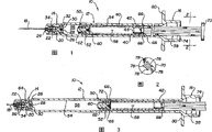
Fig. 1 is the longitudinal sectional view of first embodiment of syringe of the present invention, and it has a needle-storing chamber and separable handle, and this syringe is illustrated in the position of preparing topping up;
Fig. 2 cuts open the handle of first embodiment that gets and the thumb cutaway view by medicated cap along the line among Fig. 1 " 2-2 ";
Fig. 3 is the longitudinal sectional view of first embodiment of Fig. 1, and wherein plunger has been withdrawn into maximum topping up position and has stopped;
Fig. 4 is the longitudinal sectional view of the syringe of each figure of front, and wherein handle has been pushed to injection complete position;
Fig. 5 is the longitudinal sectional view of the syringe of each figure of front, and it is expressed: if handle is pulled back into position shown in Figure 5 from position shown in Figure 4, handle just spins off, but does not also actuate withdrawal;
Fig. 5 A is the amplification longitudinal sectional view of the mid portion of first embodiment shown in Figure 5, has expressed the needle-storing chamber before withdrawal takes place and has been in the plunger seal of position shown in Figure 5;
Fig. 5 B expresses the restraint retaining in the stack shell that line " 5B-5B " direction in Fig. 5 A sees;
Fig. 5 C is the alternative form of the restraint retaining of Fig. 5 B, and expressing the restraint retaining can be one or several radial projection;
Fig. 5 D expresses the alternative site of the restraint retaining of Fig. 5 B and 5C, and it helps to set the stroke of syringe;
Fig. 6 is the longitudinal sectional view of the syringe of each figure of front, and its entry needle has been withdrawn in the needle-storing chamber, and handle is in its complete anteposition, and thumb enters in the opening at injection sleeve rear portion by medicated cap;
Fig. 7 is the longitudinal sectional view of Fig. 6, expresses handle when pulling back handle after entry needle retraction needle-storing chamber and how separates with needle-storing chamber in the syringe of Fig. 6;
Fig. 8 is the longitudinal sectional view of the second embodiment of the present invention, this embodiment has entry needle, the needle-storing chamber of regracting installation, any latch-up structure that has the stepped handle of a plurality of ladder teeth and comprise a clip, and this mechanism now is in its primary importance near the handle rear portion;
Fig. 9 is the axonometric chart of an exemplary configurations of the clip among Fig. 8-14;
Figure 10 is the longitudinal sectional view of the syringe of Fig. 8, and its handle is pulled rearward so that fluid is drawn in the syringe, and its clip is to the forward second position motion of more close handle;
Figure 11 is the longitudinal sectional view of the disposable use retractable syringe of Fig. 8 and 10, and its handle has been pushed away fully forward and finished injection;
Figure 12 is the longitudinal sectional view of the syringe of Figure 11, and its handle is pushed forward to and surpasses abundant injection position at utmost, and makes in the entry needle retraction needle-storing chamber;
Figure 13 is the longitudinal sectional view of the alternative constructions of the second embodiment of the present invention, and wherein, handle is fixed in the rear portion of needle-storing chamber separably in the mode that is similar to first embodiment, and plunger is in abundant injection complete position;
Figure 14 is the syringe of Figure 13, and wherein plunger has further been pushed away forward from position shown in Figure 13 and made entry needle retraction needle-storing chamber;
Figure 15 is the longitudinal sectional view of the third embodiment of the present invention, it has the same retractable needle and the needle-storing chamber with each figure of front, but expressed a kind of different any latch-up structure, this any latch-up structure allows handle to be pulled rearward once to fill syringe;
Figure 16 is the three-dimensional view of the flexible collar of Figure 15, has expressed preferable a plurality of resilient tines;
Figure 17 is the longitudinal sectional view of the 3rd embodiment of Figure 15, and it is expressed handle and has been pulled back to corresponding position, position with the embodiment of Figure 10;
Figure 18 is a longitudinal sectional view, and it is illustrated in the injection process along with how the handle flexible collar that begins to travel forward is released and is engaged in handle, so as to preventing any significantly motion backward of handle;
Figure 19 is the longitudinal sectional view of the syringe of the 3rd embodiment shown in Figure 180, and wherein handle has been pushed forward to the injection completing place.
Detailed description of the present invention
In the following description, similarly part with same label.Preferably, the part shown in each figure in fact all is circle or columniform.
Fig. 1-7 has disclosed first embodiment of disposable use retractable syringe, and the remodeling of the retractable syringe shown in Fig. 1-3 of this embodiment and United States Patent (USP) 5,632,733 is relevant.Although can see the detailed description of the retractable syringe that this is preferable in listed other document in the prior art overview of this citing document and front, its principal character also will give brief description in conjunction with the present invention here.The present invention can provide a plunger handle to lock arbitrarily, even entry needle uses not withdrawal of back for the first time, this any locking can prevent that also syringe is by reuse.Be appreciated that to the invention is not restricted to concrete retracting device or structure, but it can be used to other retractable needle device, especially those finish the injection back by pushing away the retractable syringe that plunger handle triggers the withdrawal action forward.Have many kinds of devices can make entry needle draw back and the retraction plunger in vestibule in.For example, United States Patent (USP) 5,407,436 or the Pressly of Toft, the United States Patent (USP) 5,713,952 of Sr. can improve with the present invention.With regard to one situation of back, though having really, plunger handle can stop the structure of using for the second time, it only just plays this effect after the real withdrawal of syringe.
Disposable use retractable syringe of the present invention indicates totally by label " 10 " in Fig. 1.Syringe 10 has elongated hollow syringe barrel 12, and it has the rear end part 16 of fore-end 14 and opening.Retractible entry needle 18 is installed on retraction structure 20, and retraction structure 20 comprises an elongated needle holder 22, and there is a shoulder front of this needle holder 22, and this shoulder is matched with in the forward perforate 24 of fore-end 14, travels forward to stop needle holder 22.Can see that in Fig. 1 the sub-fraction of needle holder 22 stretches out in stack shell forward.The keeper 26 of a departing loop configuration separatably and frictionally 28 matches with the head 30 of the increasing of needle holder 22 along the interface.Interface 28 is oriented to the direction of withdrawal.Keeper 26 preferably presses fit in anterior 14 medial wall together with the head 30 of needle holder 22, and they withstand the withdrawal force that applied by compression spring 34 and motionless by this cooperation.The front end of spring 34 leans against on anterior 14 the ring shoulder backwards, and its rear end withstands on the ring shoulder forward of head 30 of needle holder 22, rather than is pressed on the keeper 26 that can be moved.Entry needle 18 usefulness binding agents 36 are fixed in the needle holder 22.
Syringe is by the movable parts operation that comprises handle 38, handle 38 connects (detentconnection) 42 by plug-in card and is connected in needle-storing chamber 40 separatably, and this plug-in card connects preferably the insertion snap-fit that forms between the rear end by the front end 44 of handle 38 and needle-storing chamber 40.Handle 38 preferably has band and leads the core bar 76 of rib 78 and thumb by medicated cap 70, as shown in Figure 2.Finger grip end 80 and thumb match by medicated cap 70 and allow the syringe user with one-handed performance.From Fig. 7 as seen, the front end 44 of handle 38 has annular groove 46, and it matches separatably in one or more annular projections 48 of the rear end of needle-storing chamber 40, connects 42 and form plug-in card.Handle 38 is extracted needed power from needle-storing chamber 40 keep off 66 needed power less than the restraint that needle-storing chamber 40 is pulled through in the stack shell.When pulling at, handle will break away from needle-storing chamber and needle-storing chamber will be stayed in the stack shell.
Needle-storing chamber 40 has the Tibetan spacing 58 that can hide the entry needle that stays withdrawal and the stopper 60 that can be moved, and this stopper 60 seals up the opening of chamber 58 slidably.Fore-end 50 have termination 62 foremost, this termination is used to contact keeper 26 and promotes its to break away from head 30 and arrive head 30 space 64 before that is positioned at fore-end 14 needle holders 22.This move will be finished when abundant " injection complete position " shown in Figure 4 continues push handle (movable part) automatically.From the further driving handle in the position of movable parts shown in Figure 4 circular orientation part 26 will be travelled forward again, and stopper 60 is moved backward and leave original position, so opened Tibetan spacing 58 and discharged entry needle 18, entry needle is able under the effect of spring 34 in the retraction space 58, as shown in Figure 6.So far described structure provides a kind of entry needle retractable syringe, and it can prevent acupuncture accident and be not easy to be used again because after the pin withdrawal each part uncoupling and thumb are closely filled in the rear end 16 of stack shell 12 by medicated cap mutually.If entry needle has been withdrawn, the present invention can guarantee to run into pin or other part again, if not withdrawal of entry needle also can prevent syringe quilt topping up once more.
The most important thing is, the inner surface 54 of injection sleeve 12 is provided with any latch-up structure 66, it comprises radially inwardly outstanding one or more kicks, and these kicks are designed to limit needle-storing chamber 40 and move backward and prevent that it from running out of in injection sleeve after syringe uses once.Needle-storing chamber 40 preferably has enlarged rear end 68, it can with any latch-up structure 66 co-action on the stack shell inwall.Its gap is such: it can be forced to slip over forward any latch-up structure 66 when thumb is firmly pushed thumb by medicated cap 70, but, in case being pushed away forward, the handle 38 of syringe and needle-storing chamber 40 make the rear end 68 of needle-storing chamber 40 pass through the kick 66 of any latch-up structure, anyly make this move reverse attempt all can not to reach, because handle 38 will break away from needle-storing chamber 40, shown in Fig. 5 and 7.
Fig. 1 expresses syringe and is in the position of preparing topping up.First restraint retaining, 66 (hereinafter will so be referred to as) that the kick of fixed position formed on handle 38 and needle-storing chamber 40 be pushed to the rear end 68 that makes needle-storing chamber 40 and have been in the stack shell inwall contact.The rear end 68 of needle-storing chamber 40 preferably comprises one second restraint retaining (hereinafter will so be referred to as), and it and first restraint keep off co-action, can prevent further travelling forward of moving parts, unless apply much bigger power.The local diameter that second restraint retaining is preferably the rear end of cylindrical needle retention strengthens, and it is arranged on the rearmost end of needle-storing chamber the most rightly, as shown in Figure 1.But the enlarged diameter position can be according to the requirement of geometric element from the rear end of needle-storing chamber to reach.Different enlarged diameter positions is set on the diverse location of needle-storing chamber is for so as to changing eharge stroke, so that set up different topping up volumes for different injected dose.First and second restraints retaining 66,68 has constituted any latch-up structure.
Though seem a bit big in preparation topping up position variable fluid chamber 56, in fact, it only is a quite little part of syringe maximum volume, and says so very little utterly for the syringe of 1cc or 1/2cc.As can be seen: the position of restraint retaining 66 and the length and the diameter of needle-storing chamber 40 and stack shell 12 will determine the topping up volume.The size of needle-storing chamber 40 and location should be able to be taken in whole entry needle 18 fully, so that do not have exposed needle tip after the entry needle withdrawal.
Fig. 3 expresses next step of topping up process, user optionally pulls back the shoulder block 72 of injector handle on needle-storing chamber 40 front ends and leans on first restraint retaining 66 in this step, this can give tactility of user, shows that syringe has been full of injecting fluid.
Fig. 4 expresses next step of injector operations, and entry needle has penetrated in patient's body (not shown) and plunger has been pushed to injection complete position in this step.At this moment, the fore-end of needle-storing chamber 40 is in such position, and promptly travelling forward of termination 62 can begin to make stopper 60 to return and keeper 26 is gone to advancing slip from the head 30 of the needle holder 22 of retraction structure 20 from the opening of the front end 50 of needle-storing chamber 40 in regular turn.This is to realize until thumb closely enters the opening 74 of enlarged rear end 16 of stack shell 12 by medicated cap 70 in by medicated cap 70 by pushing thumb.So just become the entry needle retracted position of Fig. 6, the retractible pin in this position together with stopper 60 retraction needle-storing chambers in its back in.Thumb has entered in the opening 74 by medicated cap 70.In this position, entry needle is withdrawn safely, and handle is filled in the opening of syringe needle tube rear end with having flushed, can prevent to be used again.
But, if user does not make entry needle withdrawal (we do not see Fig. 6 and see Fig. 5) after in the position that reaches Fig. 4, as shown in Figure 5, attempt to move movable part by handle 38 again and can only make second restraint retaining 68 that is positioned at needle-storing chamber 40 back be contacted with first restraint retaining 66, so far it can not move again.Handle portion 38 does not stay the means of any contact syringe inner body because of the release of plug-in card connection 42 has broken away from needle-storing chamber 40.Annular groove 46 on the front portion 44 of handle 38 and one or several projection 48 uncouplings.In dispose procedure, each part may produce slight deformation.Can see that from Figure 4 and 5 handle 38 inserts in the stack shell again even want to reuse syringe, the filled volume of variable liquid-filled chamber also will be not enough.
Fig. 5 A is the zoomed-in view of the mid portion between the geosutures shown in Figure 5.Wherein can be clear that shoulder block 72, it preferably is made for the circle profile of tooth projection radially on fore-end 50.The rear end part 68 of needle-storing chamber 40 has the end face 82 of dilated diameter, and the edge of this end face is resisted against on first restraint retaining 66.Can see: plug-in card projection 48 is positioned at the rear end of needle-storing chamber, and it can be sticked in the annular groove 46 of appreciable handle 38 in Fig. 5, and at this moment handle has broken away from.Fig. 5 B is a profile, and it expresses first restraint retaining 66 can be successive kick around the internal diameter of stack shell 12.Fig. 5 C expresses, and first restraint retaining 66 can be several radially inside projections of some greatly, and they are oriented to contact and to block the rear end 68 of needle-storing chamber 40, stop it to be spurred by handle 38 again.Equally, if retaining lock 66 is successive, comprise that the rear end of the needle-storing chamber of second restraint retaining 68 just can be discontinuous.As long as one or another are successive, just needn't require needle-storing chamber circumferentially by angle orientation, and if press angle orientation, needle-storing chamber just might be pulled out stack shell by handle.
Fig. 5 D expresses, the rear end of needle-storing chamber can be changed into be a straight rear end part 68 ', its size is decided to be the through hole that is fit to by between the kick of restraint retaining 66.Displacedly be, in diametric(al) projection 69 be set, as contacted by keeping off with positive latching projection 66 at the diverse location of needle-storing chamber outer surface.Diametric projection 69 can be regarded as second restraint retaining, and it is cooperated with the motion backward of restriction needle-storing chamber 40 with first restraint retaining 66.The model of action of the enlarged rear end part 68 of the needle-storing chamber among second restraint retaining 69 modes that work and each figure of front is identical, and it can be forced through the through hole between the projection 66 when travelling forward under putting on the effect of thumb by the power of medicated cap 70.Then, the projection 69 in the diametric(al) setting when user is attempted to pull back handle contacts with projection 66, and needs a ratio to make handle 38 break away from the big power of needle-storing chamber 40 needed power.A kind of alternative method that makes handle that different movement travels be arranged with respect to stack shell that Here it is.So that when injecting needed dosage, this method is useful at the stroke of setting a concrete syringe.
Fig. 8-14 has provided second embodiment of disposable use retractable syringe of the present invention, and it has the preferable retraction structure that discloses among each figure of front, to it with identical label.Made the part of changing with respect to the part among each figure of front and will cast aside the label of " ' " with adding one.The syringe of second embodiment indicates totally by label " 10 ' ".Entry needle 18 and retraction structure 20 that retractable syringe 10 ' have and the identical regracting of first embodiment are installed.It has the injection sleeve 12 changed to some extent with respect to first embodiment ', but it does not have same any latch-up structure, does not have enlarged rear end part 16 yet.Stack shell 12 ' have fore-end 14 and open back end 84.Movable handle 38 ' can be installed in stack shell 12 with moving back and forth ' in, stack shell 12 ' interior be connected in addition handle 38 ' needle-storing chamber 40 '.The stopper 60 that the fore-end 50 of plunger comprises same piston seal 52 and pushed slidably, this with first embodiment in discuss the same.The rear end part of movable handle is useful on handle is applied the thumb of power by medicated cap 86.Needle-storing chamber 40 ' or be connected in regularly or separably handle 38 ', but only be convenience in order to make.If these two movable parts are made separately, should couple together them and guarantee that they can not be separated, for example can use welding, bonding or other nonvolatil fixing means, perhaps can they are integrally molded.
Second embodiment is with the different of first embodiment: its any latch-up structure is a preferable metal clip 88, as shown in Figure 9.This clip 88 have a tongue piece 90 and on body 94 a pair of or several to the lock tooth 92.Tongue piece 90 slightly to inflection in case can with the handle 38 that is in needle-storing chamber 40 ' back ' on many stepped tooth 96 interact.
Fig. 8 represents the initial position of the disposable use retractable syringe of second embodiment.At this initial position, handle is fully pushed to preceding in injection sleeve and is contacted retraction mechanism slightly but do not cause withdrawal.The sort of contiguous sense when this can make stopper 60 run into needle holder head 30 by the operator is judged.Arbitrarily latch-up structure 88 is enclosed within handle 38 ' go up and can moves to the second position 100 from the primary importance 98 of Fig. 8, and this available simple way is accomplished, promptly pulls back handle with respect to injection sleeve and gets final product.Any latch-up structure that comprises clip 88 can only promptly move to the forward second position of more close handle from the primary importance near the handle rear portion to a direction motion.If attempt to make clip to move backward with handle, the pointed tooth 92 of setting will be engaged in stack shell 12 ' inner surface 102.Because pointed tooth 92 be tip backward, can be free to slide along stack shell inner surface 102 at clip pointed tooth 92 when stack shell 12 ' interior moves forward.Tongue piece 90 will abut on the edge of ladder tooth 96 when handle moves backward with respect to clip 88.So ladder tooth 96 just slides with respect to clip 88 when pulling back handle, and clip 88 can arrive the second position 100 of Figure 10 from the primary importance 98 of Fig. 8.Figure 10 represents is handle 38 after by entry needle 18 fluid of maximum being drawn into fluid chamber 56 ' with respect to the position of clip 88.Needle-storing chamber 40 ' just is in the front of the second position of latch-up structure 88 arbitrarily.Be that clip has constituted any latch-up structure like this, as can be seen.
Figure 11 expresses fluid in variable fluid chamber 56 by the position of handle after discharging most possibly that is when injection finishes.Can see: the intilted tongue piece 90 of clip 88 is stuck on the lower limb of ladder tooth 96, with handle 38 ' and needle-storing chamber 40 ' travel forward.Tip pointed tooth 92 backward along stack shell 12 ' inner surface slide and do not interfere travelling forward of handle.
Figure 12 expresses the syringe 10 of second embodiment ' how by pushing thumb simply by withdraw its entry needle of medicated cap 86 and the retracted position that makes handle move to Figure 12 from the injection complete position of Figure 11.As can be seen: keeper 26 is pushed from the head 30 of needle holder 22 by termination 62 and enters space 64, and since stopper 60 from needle-storing chamber 40 ' fore-end move to rear end part, needle holder that spring heads on and entry needle move backward and are withdrawn in the needle-storing chamber, and are remained there by spring 34.These parts be sized to make whole entry needle comprise its sharp-pointed needle point be withdrawn into stack shell 12 ' in.What illustrated above is that any latch-up structure that is positioned at stack shell does not influence once moving backward and once travelling forward of handle.But now, latch-up structure 88 is the second positions in its Figure 12 arbitrarily, any adverse movement of needle-storing chamber is promptly moved backward and all will be prevented by clip 88, because the pointed tooth 92 that slides be now be in penetrate stack shell 12 ' the attitude of inner surface 102, needle-storing chamber 40 ' rear end 104 be again the bottom surface that has contacted clip 88, thereby can prevent that handle and needle-storing chamber from moving backward.Because clip 88 can not move and stop needle-storing chamber 40 ' motion backward backward, can appreciate that after once using and handle can not be pulled out backward from injection sleeve.Compare the position of lower catch hoop 88 in Figure 11 and 12, can recognize: no matter whether entry needle withdraws, handle can not be drawn out exactly.So handle is locked in the stack shell after once using.Also it is apparent that: the topping up volume can by change clip 88 with respect to handle 38 ' initial position adjust, United States Patent (USP) 5531,691 and 5,562 as people such as Shonfeld, 623 is illustrated, and these two patents have been mentioned in the background technology part of preamble.
Figure 13 and 14 corresponds respectively to Figure 11 and 12.Syringe 10 in them " with Figure 11 and 12 syringe 10 ' differently only be: its handle 38 " be to be connected in needle-storing chamber 40 separably with a kind of separable connection ".Needle-storing chamber 40 " rear end part preferably have a circumferential groove in its end portion 108, and handle 38 " front end have that be fixed thereon, corresponding and can cooperate an annular radial projection 110 with annular groove 108.Separable connection 106 (releasable connection) makes the movable parts that comprises handle 38 " and needle-storing chamber 40 " become two designs of part, this is convenient to its molded respectively and assembling, and make to be standard-sized another part that changes simultaneously keeping one of them part, for example, handle can do longerly or shorter and with same needle-storing chamber 40 ", perhaps can change needle-storing chamber length and with the handle 38 of standard ".A reason that changes needle-storing chamber may be the entry needle with different length.Changing stroke also is the another kind of way that changes maximal dose.The length of stack shell can change, but the length of stack shell is not crucial, because be that clip 88 stops handle 38 " and needle-storing chamber 40 " to be drawn back after having carried out injection for the first time, the model of action of clip combines Fig. 8-12 with the front described identical.No matter whether retraction mechanism has been actuated, retreating all of handle will be prevented from.
Figure 15-19 shows the third embodiment of the present invention.The syringe of this embodiment indicates with label " 11 ".Syringe 11 is exactly the withdrawal formula syringe of Fig. 1-7, but following some difference is arranged.Until the rear end of needle-storing chamber, the part and the part among first embodiment of expression can regard identical as among Figure 15-19, and the rear end part 112 of stack shell 12 has been changed, and is in order to adapt to flexible collar structure shown in Figure 16 114.Part after the finger grip end 80 of stack shell 12 is by overstriking, the spitting image of the rear portion 16 of first embodiment.It also has opening 74, and the thumb that is used to take in handle 116 rear ends is by medicated cap 70, but the undergauge seat surface 118 in opening 74 fronts is just arranged.Form the annular groove 120 in the enlarged rear end part 112 that is in stack shell 12 before the seat 118, flexible collar 114 is installed and is fixed within it and with respect to stack shell.It will be appreciated that: flexible collar 114 comprises the structure that is positioned at stack shell inside, and after syringe used for the first time, this structure can limit the continuation of needle-storing chamber and move backward.
Handle 116 is in the back of needle-storing chamber 122 (Figure 17) and makes along its length and has a plurality of stepped teeth 124, and the ladder tooth 96 of these ladder teeth and second embodiment is the same.The sliding part that has lasso 126 forms on the handle 116, lasso 126 comprise the dogging shoulder 128 at the edge 130 that is constructed to be permeable to block arbitrary ladder tooth 124, and lasso 126 is split type ring-shaped work pieces, so that it can install on the handle.Can be mounted and fixed on the position to thumb by medicated cap 70 after lasso is installed on the shaft of handle 116, perhaps handle can be that two parts are dressed up.
Flexible collar 114 preferably has annular body 132 and opened gap 134, and the gap makes the annular body can be by mild compression, so that it can be packed in the annular groove 120 by undergauge seat 118.Flexible collar 114 has a plurality of resilient tines 136, separates in handle, as shown in figure 15 at the slided rear end part of lasso 126 of initial these resilient tines of installment state.This is the initial position of handle, and it is corresponding to the original position of Fig. 1 or Fig. 8.Slight undergauge place 138 on the stack shell 12 can stop lasso 126 to be pulled back to motion backward again behind the position of Figure 17 with handle 116, and pulling back handle 116 can be with in the fluid suction variable volume fluid chamber 156 (not showing among Figure 17, referring to Fig. 3).Clear in order to represent, ladder tooth 124 and dogging shoulder 128 are by exaggerative slightly, and they allow handle to be withdrawn into the preparation injection position of Figure 17 without barrier in fact.This is to pull back for the first time of handle 116 and needle-storing chamber 122.The rear end of needle-storing chamber 122 has stop end face 140, and this end face leans against on the end face of lasso 126, as shown in figure 17 when handle is fully retracted.Lasso 126 still keeps resilient tines not contact with handle 116 in Figure 17.
Figure 18 shows: when the handle 116 of syringe 11 by be pressed in thumb by the effect of the power on the medicated cap 70 under from the position of Figure 17 forward, what can take place towards the position of Figure 18 and during the final position that arrives Figure 19.With what take place be: the dogging shoulder 128 of sliding part that is lasso 126 will be stuck on the edge 130 of ladder tooth 124, travel forward and break away from flexible collar 114 with it, this makes resilient tines 136 ride on the ladder tooth 124 along with handle 116 travels forward, and each tooth let slip one by one, arrive the position of Figure 19 until handle 116.
Figure 19 shows injection complete position, and wherein remaining parts is corresponding to the position of Fig. 4 or Figure 13.The needle-storing chamber fore-end 50 the same with Fig. 1 touched the forward retraction mechanism 20 of syringe, and fluid is discharged from entry needle 18.Resilient tines 136 falls in the annular groove 142 of handle 116 rear end parts.But, should be realized that from the acute angle of resilient tines 136 with respect to ladder tooth 124: can not handle 116 pull back from the position of Figure 18 or from the arbitrary centre position between the position of the position of Figure 15 and Figure 19, because resilient tines 136 will penetrate arbitrary ladder tooth of contact with it that handle 116 is stuck in stack shell 12.So, flexible collar 114 provides any latch-up structure that is positioned at stack shell by being engaged in movable part a fixed position, and this any latch-up structure does not influence once moving backward of movable parts (handle and needle-storing chamber) and travelling forward of the degree that once moves forward to fullest.But because handle can not be pulled back for the second time, the continuation of needle-storing chamber is moved backward and is prevented, thereby needle-storing chamber is maintained in the stack shell.
At last, finishing after the injection position of Figure 19, push thumb at last more forward by medicated cap 70 from the position of Figure 19, the motion of handle will be actuated the withdrawal action of regracting part, and its result is shown in Fig. 6,12 and 14.Entry needle is with in the retraction needle-storing chamber 122 and be collected in the stack shell.Therefore, among these three embodiment, the withdrawal action of plunger activated can be identical with retraction mechanism at all, and any latch-up structure of motion backward that just is used to limit needle-storing chamber is different.
Best mode is, but each part is normally used polypropylene with the plastics manufacturing of conventional injection molding.Piston seal is conventional, and clip metal preferably.
Although above accompanying drawings several embodiments of the present invention,, should be appreciated that the invention is not restricted to this several specific embodiments, those skilled in the art that can make various other change and modification in spiritual scope of the present invention.
Claims (35)
1. disposable use withdrawal formula syringe with needle-storing chamber of one handle operation, described needle-storing chamber can not leave injection sleeve, and this syringe comprises:
An elongated hollow syringe barrel with a front end and an open back end;
One that be installed on retraction structure in the front end of described injection sleeve and be biased in the retractable needle of withdrawal backward;
Movable parts, described movable parts comprises that one is connected in the handle of described needle-storing chamber, described needle-storing chamber is installed hermetically and slidably by means of the described handle that stretches out from the described open back end of described stack shell, in described injection sleeve, moving, that the front end of described needle-storing chamber has a sealing but can open opening with the entry needle of taking in withdrawal;
The withdrawal of the described needle-storing chamber of described entry needle retraction action by described needle-storing chamber respond described handle after finishing a shot motion and being triggered of producing facing to travelling forward of described retraction structure;
Be arranged on any latch-up structure in the described injection sleeve, this any latch-up structure can limit the motion backward of described needle-storing chamber and stop it to be pulled out in described injection sleeve after described syringe once uses; Thereby the entry needle of described withdrawal is collected in the needle-storing chamber that is in the described injection sleeve after once using safely, is not easy again owing to pushing away or drawing described handle to be moved out of.
2. disposable use withdrawal formula syringe as claimed in claim 1 is characterized in that described needle-storing chamber is connected in described handle.
3. disposable use withdrawal formula syringe as claimed in claim 1 is characterized in that described needle-storing chamber is to be connected in described handle separably.
4. disposable use withdrawal formula syringe as claimed in claim 1, it is characterized in that, described any latch-up structure comprise be arranged in the described stack shell engageable in the structure of movable parts, this structure is configured to not influence the once motion and once move forward to travelling forward of fullest degree backward of described movable parts, but can stop the motion backward subsequently of described needle-storing chamber and described needle-storing chamber is remained in the described injection sleeve.
5. disposable use withdrawal formula syringe as claimed in claim 4, it is characterized in that the structure of motion backward subsequently that is arranged on the described needle-storing chamber of the internal energy prevention of described stack shell is in one with respect to the fixed position of described stack shell in the use of described syringe.
6. disposable use withdrawal formula syringe as claimed in claim 5, it is characterized in that, the structure that is in a fixed position with respect to described stack shell in described stack shell comprises a diameter shrinkage part of the described barrel diameter that constitutes first restraint retaining, simultaneously described needle-storing chamber have constitute second restraint retaining along the diametric(al) enlarged portion, wherein, described second restraint retaining can be forced to keep off by described first restraint forward when the described handle of pushing, but its hinders the motion backward that is caused by the described handle of pulling.
7. disposable use withdrawal formula syringe as claimed in claim 6, it is characterized in that, described handle is connected in described needle-storing chamber separably, make their isolating separating forces less than forcing described second restraint retaining to keep off needed power by described first restraint backward, so their separation will be stayed described needle-storing chamber in the described stack shell.
8. disposable use withdrawal formula syringe as claimed in claim 7 is characterized in that, described handle and described needle-storing chamber are the fractures of the release of dependence separating part rather than separating part and realize isolating.
9. disposable use withdrawal formula syringe as claimed in claim 8, it is characterized in that, described needle-storing chamber has the fore-end that has a dogging shoulder, this dogging shoulder can be forced through described first restraint retaining before described second restraint retaining moves through described first restraint retaining when the described handle of pushing, this dogging shoulder limits the amount of rearward travel of described movable parts, to set up the design maximum topping up volume of described syringe.
10. disposable use withdrawal formula syringe as claimed in claim 5, it is characterized in that, be arranged on described stack shell inside, can limit the sporting backward structure subsequently of described needle-storing chamber and comprise a structure in the open back end that is installed in described stack shell by remaining on a fixed position.
11. disposable use withdrawal formula syringe as claimed in claim 5, it is characterized in that, described structure comprises a flexible collar, this clip can be pushed away forward at described handle and positively is engaged in described handle after finishing a shot, in case thereby this clip meshed described handle, just can stop described handle to be continued to pull back.
12. disposable use withdrawal formula syringe as claimed in claim 11, it is characterized in that, described handle comprises the thumb that is used for pushing away described handle forward by medicated cap, closely is accommodated in the described open back end of described stack shell by medicated cap at the withdrawal of described entry needle described thumb when fully pushing described plunger activated.
13. disposable use withdrawal formula syringe as claimed in claim 11, it is characterized in that, the described handle that extends later in described needle-storing chamber is made into the tooth of stairstepping and comprises a sliding part thereon along its length, this sliding part separates described flexible collar in described handle when initial installment state, thereby allow described plunger to be pulled rearward so that described syringe suction fluid, this sliding part travels forward when described handle is urged then, makes it to be able to contact with described handle thereby discharged flexible collar.
14. disposable use withdrawal formula syringe as claimed in claim 5, it is characterized in that, be arranged on described stack shell inside, the sporting backward described structure subsequently that can limit described needle-storing chamber comprises a flexible collar and a sliding part that contacts with described handle that is installed in the interior fixed position of described open back end of described stack shell, described sliding part keeps described flexible collar to leave described handle when described handle is pulled rearward, and described sliding part has discharged described flexible collar by travelling forward with described handle and makes it to be able to contact with described handle when described handle is pushed away forward in described stack shell.
15. disposable use withdrawal formula syringe as claimed in claim 4, it is characterized in that, be arranged on the inner described sporting backward structure subsequently that can limit described needle-storing chamber of described stack shell and in the use of syringe, can change its position with respect to described stack shell.
16. disposable use withdrawal formula syringe as claimed in claim 15, it is characterized in that, described structure comprises a flexible collar, described handle be pushed into forward finish a shot after, this flexible collar can positively be engaged in described handle, in case and this flexible collar has meshed described handle, it just can stop described handle to be pulled back unceasingly.
17. disposable use withdrawal formula syringe as claimed in claim 15, it is characterized in that, described handle comprises and is used for pushing away forward the thumb of described handle by medicated cap, when fully pushing described plunger activated, described thumb closely is accommodated in the described open back end of described stack shell by medicated cap in the withdrawal of described entry needle.
18. disposable syringe with an injection sleeve, in described disposable syringe, it is that stretch out from its rear end and be mounted to and can make restricted reciprocating movable handle within it that injection sleeve has an entry needle that is used for injecting fluid that stretches out from its front end and one, described movable handle comprises a fore-end, this fore-end has the piston that contacts with the inner surface slipper seal of described stack shell, wherein, described piston has been set up the variable injecting fluid chamber that is in the described stack shell; Described movable handle also comprises a rear end part, this rear end part has one and is used for described handle is applied the thumb of thumb thrust by medicated cap and any latch-up structure that is arranged in the described stack shell, this any latch-up structure can be in the motion and the described variable fluid chamber of injecting fluid suction and described handle travelled forward for the first time and second time of limiting described handle after injecting fluid moves backward backward for the first time of described handle, and its improvement comprises:
Described entry needle is one to be installed on the retractable needle of the retraction structure in the front end of described stack shell, and this entry needle stretches out in its retracted position and not biased to be retracted in retracted position;
The fore-end of described handle is configured to trigger the action of described retraction structure and makes described entry needle withdrawal, and described fore-end has the needle-storing chamber of the entry needle that is used to take in withdrawal and is positioned at the described piston of described variable fluid chamber back;
Described needle-storing chamber has a front end and a part that strengthens in diametric(al);
Described any latch-up structure is one and is positioned to by the restraint in the scope that be limited in described stack shell of moving backward of described needle-storing chamber being kept off with the contacting of described enlarged portion of described needle-storing chamber;
If attempt by the rear end part that draws described handle described needle-storing chamber to be pulled through described restraint retaining, the rear end part of described handle breaks away from described fore-end; And
Wherein, even the not withdrawal after once using of described entry needle, described syringe also can not be used again.
19. disposable syringe as claimed in claim 18, it is characterized in that, described restraint retaining is a structure that is formed in the described stack shell, and this structure allows the described fore-end of described handle and described needle-storing chamber to be shifted onto by medicated cap by the pushing thumb front of described restraint retaining; And
If described needle-storing chamber is pulled rearward, it contacts described restraint retaining and produces resistance when it moves backward, this resistance is guaranteed that whereby entry needle will be retained in the described stack shell, thereby is prevented that described syringe from being used for the second time greater than the needed power of the separation that makes described handle.
20. disposable use withdrawal formula syringe as claimed in claim 19 is characterized in that, described handle and described needle-storing chamber are the release of dependence separating part rather than their fracture and realize isolating.
21. disposable use withdrawal formula syringe as claimed in claim 19 is characterized in that the rear end part of described handle is connected in described needle-storing chamber separably with a kind of snap-fit.
22. disposable use withdrawal formula syringe as claimed in claim 19, it is characterized in that, described needle-storing chamber has a dogging shoulder near its front end, this dogging shoulder can be forced to forward by described restraint retaining when pushing described handle, and this dogging shoulder is formed at described handle and is pulled rearward and can moves backward when setting up the maximum volume of variable fluid chamber and come to described restraint and block.
23. the disposable use withdrawal formula syringe with operating grip, its operating grip can not be pulled out in injection sleeve after syringe once uses again, and this syringe comprises:
An elongated hollow syringe barrel with a front end and an open back end;
One that be installed on retraction structure in the front end of described injection sleeve and be biased in the retractable needle of retracted orientation backward;
One plunger, it comprises:
Movable handle in described injection sleeve, described handle has: a fore-end, this fore-end have a piston that contacts with the inner surface slipper seal of described stack shell;
A rear end part, the rearmost end of this rear end part have one for thumb to the thumb of described handle applied thrust by medicated cap; And,
Being used in the fore-end of described handle is taken in the needle-storing chamber of retractible entry needle;
Be arranged on any latch-up structure in the described injection sleeve, this any latch-up structure can limit the motion backward of described handle and stop it to be pulled out in described injection sleeve after described syringe once uses; Thereby the described entry needle after using is collected in the described needle-storing chamber that is in the described injection sleeve safely, and can not be pushed or draw described plunger again and move.
24. disposable use withdrawal formula syringe as claimed in claim 23, it is characterized in that, described handle carries described any latch-up structure, described any latch-up structure only can be to a direction motion, promptly from moving to the second position of more close described handle front end near the primary importance of described handle rear end, described any latch-up structure is configured to positively to be engaged in described injection sleeve after it moves to the front of described primary importance and limits described needle-storing chamber and move backward.
25. disposable use withdrawal formula syringe as claimed in claim 24 is characterized in that described needle-storing chamber is located in the front of the described second position of described any latch-up structure.
26. disposable use withdrawal formula syringe as claimed in claim 25, it is characterized in that, fully pushed and after having carried out a shot at described plunger, thumb is exerted pressure by medicated cap to the described thumb of described plunger rearmost end more just will impel described entry needle withdrawal.
27. disposable use withdrawal formula syringe as claimed in claim 25, it is characterized in that, the described rear end part of described handle has a plurality of ladder teeth, and described any latch-up structure comprises that has the clip with respect to the tongue piece of bending in the described ladder teeth directional, described tongue piece allows described clip to travel forward and stops it to move backward, described clip has the tip of at least one outside bending, and this tip is engageable to stop described handle to be drawn back in described injection sleeve.
28. disposable use withdrawal formula syringe as claimed in claim 27 is characterized in that, described clip surrounds the part of described ladder tooth of described handle rear end part rather than they are whole.
29. disposable use withdrawal formula syringe as claimed in claim 23, it is characterized in that, be positioned at described injection sleeve, can limit described any latch-up structure that described handle moves backward and comprise that one is installed in the structure that a fixed position is used with respect to described stack shell.
30. disposable use withdrawal formula syringe as claimed in claim 29 is characterized in that, the described structure that is installed in a fixed position with respect to described stack shell is arranged in the open back end of described stack shell.
31. disposable use withdrawal formula syringe as claimed in claim 30, it is characterized in that, described handle comprises and is used for pushing forward the thumb of described handle by medicated cap, when the abundant pushing of described plunger had triggered the withdrawal of described entry needle, described thumb closely was accommodated in the open back end of described stack shell by medicated cap.
32. disposable use withdrawal formula syringe as claimed in claim 30, it is characterized in that, being installed in the open back end of described stack shell described structure with respect to a fixed position of described stack shell is one and has one or several flexible collar of the tip of bending forward, in described handle initial moves with the process with the described stack shell of injecting fluid suction backward, these tips are being isolated by a lasso on the described handle and are not being contacted with described handle, make described handle do once motion backward from the relative stack shell of initial anterior locations, travel forward and break away from and the contacting of described flexible collar at be pressed when injecting described lasso of described plunger then, so described flexible collar and described engagement and stop it to move backward.
33. disposable use withdrawal formula syringe as claimed in claim 32, it is characterized in that, the rear end part of described handle has a plurality of ladder teeth, described slip cap snare is on these ladder teeth, the inner surface that cone angle is arranged of described lasso allows described plunger handle to move backward with respect to described slip lasso, can travel forward with described handle and described slip lasso is engaged in one of ladder tooth of described handle by its described inner surface.
34. a disposable syringe comprises:
An elongated hollow syringe barrel with a front end and an open back end;
An entry needle that is installed on the fore-end of described stack shell;
But fixed handle that is installed in reciprocating two parts in the described stack shell, described handle has a front end head and a handle portion that is connected in described head separably, and described front end head has a piston that contacts with the inner surface slipper seal of described stack shell;
A lock that is installed in the described stack shell, when described head and described handle portion were inserted into described open back end and have forward power to put on described handle portion, described lock allowed described head movement by described lock;
After having passed through described lock forward, when pulling back described handle portion, described handle portion can with described head part from, the fracture that described head discharges described handle portion rather than plays the part of centrifugation under the effect of the described isolating pinning force that relies on described lock realizes.
35. disposable syringe as claimed in claim 34 is characterized in that, described entry needle is the retractable needle that is installed on the fore-end of described stack shell retractedly.
Applications Claiming Priority (3)
| Application Number | Priority Date | Filing Date | Title |
|---|---|---|---|
| US09/978,906 US6494863B1 (en) | 2001-10-15 | 2001-10-15 | One-use retracting syringe with positive needle retention |
| PCT/US2002/033003 WO2004060451A1 (en) | 2001-10-15 | 2002-12-02 | One-use retracting syringe with positive needle retention |
| OA1200400204A OA12765A (en) | 2001-10-15 | 2002-12-02 | One-use retracting syringe with positive needle retention. |
Publications (2)
| Publication Number | Publication Date |
|---|---|
| CN1617751A CN1617751A (en) | 2005-05-18 |
| CN100360196C true CN100360196C (en) | 2008-01-09 |
Family
ID=38137345
Family Applications (1)
| Application Number | Title | Priority Date | Filing Date |
|---|---|---|---|
| CNB028277716A Expired - Fee Related CN100360196C (en) | 2001-10-15 | 2002-12-02 | Disposable contractable syringe capable of reliably contracting after use |
Country Status (17)
| Country | Link |
|---|---|
| US (1) | US6494863B1 (en) |
| EP (1) | EP1567212B1 (en) |
| JP (1) | JP2005524513A (en) |
| CN (1) | CN100360196C (en) |
| AP (1) | AP1728A (en) |
| AT (1) | ATE480277T1 (en) |
| AU (2) | AU2002367591B8 (en) |
| BR (1) | BR0212684B1 (en) |
| CA (1) | CA2455160C (en) |
| DE (1) | DE60237647D1 (en) |
| DK (1) | DK1567212T3 (en) |
| ES (1) | ES2348255T3 (en) |
| HK (1) | HK1077237A1 (en) |
| OA (1) | OA12765A (en) |
| PT (1) | PT1567212E (en) |
| UA (1) | UA77204C2 (en) |
| WO (1) | WO2004060451A1 (en) |
Cited By (1)
| Publication number | Priority date | Publication date | Assignee | Title |
|---|---|---|---|---|
| CN105120934A (en) * | 2013-12-31 | 2015-12-02 | Saferwith有限公司 | Syringe needle assembly, and safety syringe and safety syringe apparatus using same |
Families Citing this family (102)
| Publication number | Priority date | Publication date | Assignee | Title |
|---|---|---|---|---|
| US6387078B1 (en) * | 2000-12-21 | 2002-05-14 | Gillespie, Iii Richard D. | Automatic mixing and injecting apparatus |
| AUPR373001A0 (en) | 2001-03-14 | 2001-04-12 | Glenord Pty Ltd | Improved non-reusable syringe |
| CA2453972C (en) * | 2001-07-20 | 2009-07-14 | Chin-Fu Liao | An automatically retractable safety syringe |
| US6991618B2 (en) * | 2001-09-24 | 2006-01-31 | Becton Dickinson And Company | Single use syringe and plunger rod locking device therefor |
| US6986756B2 (en) * | 2001-09-24 | 2006-01-17 | Becton, Dickinson And Company | Single use syringe and plunger rod locking device therefor |
| US8048031B2 (en) * | 2001-10-26 | 2011-11-01 | Retractable Technologies, Inc. | IV catheter introducer |
| TW563555U (en) * | 2002-02-08 | 2003-11-21 | Jian-Wei Jung | Injector capable of controlling the fastening of needle seat and easily retractable |
| US7185451B2 (en) * | 2002-09-17 | 2007-03-06 | Fuji Jukogyo Kabushiki Kaisha | License plate holding bracket and the holding structure thereof |
| US6790197B2 (en) | 2002-09-25 | 2004-09-14 | Becton Dickinson And Company | Single use syringe and plunger rod locking device therefor |
| US20040059294A1 (en) * | 2002-09-25 | 2004-03-25 | Pelkey Brian J. | Single use syringe and plunger rod locking device therefor |
| EP1442763A1 (en) * | 2003-01-28 | 2004-08-04 | Chung-Yu Yang | Safety syringe with needle retracted by vacuum |
| GB0315600D0 (en) * | 2003-07-04 | 2003-08-13 | Owen Mumford Ltd | Improvements relating to automatic injection devices |
| IL157981A (en) | 2003-09-17 | 2014-01-30 | Elcam Medical Agricultural Cooperative Ass Ltd | Auto-injector |
| IL157984A (en) | 2003-09-17 | 2015-02-26 | Dali Medical Devices Ltd | Autoneedle |
| US20050096597A1 (en) * | 2003-11-03 | 2005-05-05 | Becton, Dickinson And Company | Safety shield system for a syringe |
| US7101351B2 (en) * | 2003-11-03 | 2006-09-05 | Becton, Dickinson And Company | Safety device for a syringe |
| US7497847B2 (en) * | 2003-11-03 | 2009-03-03 | Becton, Dickinson And Company | Safety shield system for a syringe |
| US7468054B2 (en) * | 2003-11-03 | 2008-12-23 | Becton, Dickinson And Company | Safety shield system for a syringe |
| JP4460278B2 (en) * | 2003-12-17 | 2010-05-12 | 株式会社大協精工 | Seal plug for syringe and prefilled syringe |
| GB0329269D0 (en) * | 2003-12-18 | 2004-01-21 | Id Tech Ltd | Syringe |
| US20050159706A1 (en) * | 2004-01-20 | 2005-07-21 | Becton, Dickinson And Company | Medical syringe with safety shield system |
| US20050159709A1 (en) * | 2004-01-20 | 2005-07-21 | Becton, Dickinson And Company | Safety shield system for a plastic syringe |
| US7604613B2 (en) * | 2004-01-20 | 2009-10-20 | Beckton, Dickinson And Company | Syringe having a retractable needle |
| US7344517B2 (en) * | 2004-01-20 | 2008-03-18 | Becton, Dickinson And Company | Syringe having a retractable needle |
| WO2005072797A1 (en) * | 2004-01-28 | 2005-08-11 | Unitract Syringe Pty Ltd | One use syringe with ratchet on plunger and pawl on body |
| NL1025669C2 (en) * | 2004-03-09 | 2005-09-12 | Advanced Protective Injection | Injection syringe with stroke limiter. |
| IL160891A0 (en) | 2004-03-16 | 2004-08-31 | Auto-mix needle | |
| GB0414054D0 (en) | 2004-06-23 | 2004-07-28 | Owen Mumford Ltd | Improvements relating to automatic injection devices |
| US20060079839A1 (en) * | 2004-06-29 | 2006-04-13 | Becton, Dickinson And Company | Single-use syringe |
| EP1786496B1 (en) | 2004-09-03 | 2015-01-21 | L.O.M. Laboratories Inc. | Gas-actuated retractable syringe |
| CA2584106C (en) | 2004-10-14 | 2011-09-06 | Safety Medical International, Incorporated | Safety medical syringe with retractable needle |
| WO2006083876A2 (en) | 2005-02-01 | 2006-08-10 | Intelliject, Llc | Devices, systems, and methods for medicament delivery |
| US7648483B2 (en) | 2004-11-22 | 2010-01-19 | Intelliject, Inc. | Devices, systems and methods for medicament delivery |
| CA2586525C (en) | 2004-11-22 | 2013-01-15 | Intelliject, Llc | Devices, systems, and methods for medicament delivery |
| US7648482B2 (en) | 2004-11-22 | 2010-01-19 | Intelliject, Inc. | Devices, systems, and methods for medicament delivery |
| US11590286B2 (en) | 2004-11-22 | 2023-02-28 | Kaleo, Inc. | Devices, systems and methods for medicament delivery |
| US7947017B2 (en) | 2004-11-22 | 2011-05-24 | Intelliject, Inc. | Devices, systems and methods for medicament delivery |
| US10737028B2 (en) | 2004-11-22 | 2020-08-11 | Kaleo, Inc. | Devices, systems and methods for medicament delivery |
| CN101484198A (en) * | 2004-12-09 | 2009-07-15 | 韦斯特制药服务公司 | Breech loaded fixed needle syringe and automatic injection device having the same |
| US9022980B2 (en) | 2005-02-01 | 2015-05-05 | Kaleo, Inc. | Medical injector simulation device |
| US8231573B2 (en) | 2005-02-01 | 2012-07-31 | Intelliject, Inc. | Medicament delivery device having an electronic circuit system |
| US7731686B2 (en) | 2005-02-01 | 2010-06-08 | Intelliject, Inc. | Devices, systems and methods for medicament delivery |
| US8361026B2 (en) | 2005-02-01 | 2013-01-29 | Intelliject, Inc. | Apparatus and methods for self-administration of vaccines and other medicaments |
| US8206360B2 (en) | 2005-02-01 | 2012-06-26 | Intelliject, Inc. | Devices, systems and methods for medicament delivery |
| US8062252B2 (en) | 2005-02-18 | 2011-11-22 | Becton, Dickinson And Company | Safety shield system for a syringe |
| US7278986B1 (en) | 2005-03-09 | 2007-10-09 | Frost Robert J | Safety syringe with needle |
| CN101282751B (en) | 2005-07-18 | 2011-01-12 | 韦斯特制药服务公司 | Auto-injection syringe having vent device |
| US8591473B2 (en) | 2005-09-22 | 2013-11-26 | Covidien Lp | Manually retracted safety needle with rigid wing structure |
| JP2009509585A (en) * | 2005-09-22 | 2009-03-12 | タイコ・ヘルスケアー・グループ・エルピー | Safety needle with locking mechanism |
| BRPI0616379A2 (en) | 2005-09-22 | 2011-06-21 | Tyco Healthcare | non-axial return spring for safety needle |
| EP1933904B1 (en) * | 2005-09-22 | 2015-11-11 | Covidien LP | Needle retraction structure |
| US20070073226A1 (en) * | 2005-09-23 | 2007-03-29 | John Polidoro | Syringe |
| AU2006315063A1 (en) * | 2005-11-15 | 2007-05-24 | Global Medisafe Holdings Pty Limited | Safety syringe with plunger locking means |
| US7988675B2 (en) | 2005-12-08 | 2011-08-02 | West Pharmaceutical Services Of Delaware, Inc. | Automatic injection and retraction devices for use with pre-filled syringe cartridges |
| US7846135B2 (en) | 2006-02-24 | 2010-12-07 | Midland Medical Holding LLC | Retractable needle syringe with needle trap |
| CN100391554C (en) * | 2006-04-13 | 2008-06-04 | 林作钱 | Safe medical syringe with needle capable of automatically retracting |
| CA2651992A1 (en) | 2006-06-30 | 2008-01-10 | Abbott Biotechnology Ltd. | Automatic injection device |
| US8449505B2 (en) * | 2006-11-17 | 2013-05-28 | Bencha International Group Inc. | Automatically retractable medically safety injector and plunger combination thereof |
| WO2008091838A2 (en) | 2007-01-22 | 2008-07-31 | Intelliject, Inc. | Medical injector with compliance tracking and monitoring |
| CN100450560C (en) * | 2007-02-12 | 2009-01-14 | 林作钱 | Self-destroying insulin injector |
| TW200920432A (en) * | 2007-11-12 | 2009-05-16 | ming-zheng Xu | Disposable syringe with pre-loaded medicine |
| US7976510B2 (en) | 2008-02-28 | 2011-07-12 | Becton, Dickinson And Company | Syringe with adjustable two piece plunger rod |
| US8172813B2 (en) * | 2008-02-28 | 2012-05-08 | Becton, Dickinson And Company | Syringe with two piece plunger rod |
| US9259533B2 (en) * | 2008-03-31 | 2016-02-16 | Covidien Lp | Safety needle with spring biased retraction mechanism |
| USD994111S1 (en) | 2008-05-12 | 2023-08-01 | Kaleo, Inc. | Medicament delivery device cover |
| US20090306601A1 (en) * | 2008-06-10 | 2009-12-10 | Shaw Thomas J | Fluid Flow Control Device with Retractable Cannula |
| CN101480511B (en) * | 2009-02-08 | 2011-10-05 | 浙江康康医疗器械有限公司 | Disposable safety syringe with syringe needle capable of automatically retracting |
| BRPI1012162A2 (en) | 2009-04-29 | 2016-01-12 | Abbott Biotech Ltd | automatic injection device |
| US8758301B2 (en) | 2009-12-15 | 2014-06-24 | Abbvie Biotechnology Ltd | Firing button for automatic injection device |
| KR102071212B1 (en) | 2010-04-21 | 2020-01-30 | 애브비 바이오테크놀로지 리미티드 | Wearable automatic injection device for controlled delivery of therapeutic agents |
| CA3081311C (en) * | 2010-06-09 | 2022-11-29 | Valeritas, Inc. | Fluid delivery device needle retraction mechanisms, cartridges and expandable hydraulic fluid seals |
| US8992477B2 (en) | 2011-01-24 | 2015-03-31 | Elcam Agricultural Cooperative Association Ltd. | Injector |
| SG192119A1 (en) | 2011-01-24 | 2013-08-30 | Abbvie Biotechnology Ltd | Automatic injection devices having overmolded gripping surfaces |
| PE20141543A1 (en) | 2011-01-24 | 2014-11-23 | Abbvie Biotechnology Ltd | EXTRACTION OF NEEDLE GUARDS FROM SYRINGES AND AUTOMATIC INJECTION DEVICES |
| US9173999B2 (en) | 2011-01-26 | 2015-11-03 | Kaleo, Inc. | Devices and methods for delivering medicaments from a multi-chamber container |
| US8627816B2 (en) | 2011-02-28 | 2014-01-14 | Intelliject, Inc. | Medicament delivery device for administration of opioid antagonists including formulations for naloxone |
| US8939943B2 (en) | 2011-01-26 | 2015-01-27 | Kaleo, Inc. | Medicament delivery device for administration of opioid antagonists including formulations for naloxone |
| US8702653B2 (en) | 2012-02-23 | 2014-04-22 | Unitract Syringe Pty Ltd | Retractable needle safety syringes |
| PT2817047T (en) | 2012-02-23 | 2018-11-21 | Unl Holdings Llc | Devices for targeted delivery of therapeutic implants |
| US10272234B2 (en) | 2012-02-23 | 2019-04-30 | Unl Holdings Llc | Devices for targeted delivery of therapeutic implants |
| USD752214S1 (en) | 2012-04-09 | 2016-03-22 | Becton, Dickinson And Company | Needle hub for medical syringe |
| US9272099B2 (en) | 2012-04-09 | 2016-03-01 | Becton, Dickinson And Company | Syringe with visually coded needle hub |
| USD755371S1 (en) | 2012-04-09 | 2016-05-03 | Becton, Dickinson And Company | Needle hub for medical syringe |
| US9522235B2 (en) | 2012-05-22 | 2016-12-20 | Kaleo, Inc. | Devices and methods for delivering medicaments from a multi-chamber container |
| NZ708689A (en) | 2012-11-09 | 2017-11-24 | Iinjec Tech Inc | Fluid delivery device and method |
| GB2526948A (en) | 2012-12-27 | 2015-12-09 | Kaleo Inc | Systems for locating and interacting with medicament delivery devices |
| JP6040025B2 (en) * | 2012-12-28 | 2016-12-07 | 株式会社大協精工 | Medical syringe |
| US9517307B2 (en) | 2014-07-18 | 2016-12-13 | Kaleo, Inc. | Devices and methods for delivering opioid antagonists including formulations for naloxone |
| US10258502B2 (en) | 2014-09-18 | 2019-04-16 | Orbit Biomedical Limited | Therapeutic agent delivery device |
| AU2015337782B2 (en) | 2014-10-31 | 2020-02-13 | L.O.M. Laboratories Inc. | Retractable needle syringe |
| WO2016115628A1 (en) | 2015-01-20 | 2016-07-28 | L.O.M. Laboratories Inc. | Retractable needle syringe with unitary propellant release module |
| CN104606747B (en) * | 2015-02-10 | 2018-02-27 | 四川省人民医院 | A kind of anti-pricking wound syringe of side neck formula |
| CA2980004C (en) | 2015-03-24 | 2023-10-10 | Kaleo, Inc. | Devices and methods for delivering a lyophilized medicament |
| WO2017004345A1 (en) | 2015-06-30 | 2017-01-05 | Kaleo, Inc. | Auto-injectors for administration of a medicament within a prefilled syringe |
| KR101660906B1 (en) * | 2016-06-13 | 2016-09-29 | 주식회사 대일라바테크 | A disposable syringes for reuse preventing |
| US10688244B2 (en) | 2016-12-23 | 2020-06-23 | Kaleo, Inc. | Medicament delivery device and methods for delivering drugs to infants and children |
| US10332623B2 (en) | 2017-01-17 | 2019-06-25 | Kaleo, Inc. | Medicament delivery devices with wireless connectivity and event detection |
| CN107137791B (en) * | 2017-05-25 | 2023-11-17 | 中国人民解放军第二军医大学 | Double-injector linkage fixing device |
| IT201800005604A1 (en) * | 2018-05-22 | 2018-08-22 | SAFETY AND FILLING SYSTEM FOR RETRACTABLE NEEDLE SYRINGES | |
| US11929160B2 (en) | 2018-07-16 | 2024-03-12 | Kaleo, Inc. | Medicament delivery devices with wireless connectivity and compliance detection |
| US11167087B2 (en) | 2019-08-09 | 2021-11-09 | Kaleo, Inc. | Devices and methods for delivery of substances within a prefilled syringe |
| CN114796723B (en) * | 2022-04-26 | 2023-10-20 | 盐城工学院 | Booster for filtering injector |
Citations (5)
| Publication number | Priority date | Publication date | Assignee | Title |
|---|---|---|---|---|
| US4973310A (en) * | 1988-12-30 | 1990-11-27 | Becton, Dickinson And Company | Single-use syringe |
| US5562623A (en) * | 1994-02-14 | 1996-10-08 | Univec | Single-use syringe assembly including spring clip lock and plunger |
| US6015438A (en) * | 1997-11-14 | 2000-01-18 | Retractable Technologies Inc. | Full displacement retractable syringe |
| US6090077A (en) * | 1995-05-11 | 2000-07-18 | Shaw; Thomas J. | Syringe plunger assembly and barrel |
| US6273870B1 (en) * | 2000-05-19 | 2001-08-14 | Retrax Safety Systems, Inc. | Retractable needle and syringe combination |
Family Cites Families (15)
| Publication number | Priority date | Publication date | Assignee | Title |
|---|---|---|---|---|
| US5000737A (en) | 1987-09-18 | 1991-03-19 | Program For Appropriate Technology In Health (Path) | Single use disposable syringe |
| DE3879678T2 (en) * | 1987-11-06 | 1993-09-30 | Louis Paul Ellgass | DISPOSABLE SYRINGE. |
| DE8804656U1 (en) * | 1988-04-08 | 1988-08-04 | Bader, Mohandes, 2350 Neumuenster, De | |
| US6344031B1 (en) * | 1989-03-22 | 2002-02-05 | Laurel A. Novacek | Safety syringe needle device with interchangeable and retractable needle platform |
| US4961728A (en) | 1988-12-30 | 1990-10-09 | Becton, Dickinson And Company | Single-use syringe having misuse resistant features |
| SU1678377A1 (en) * | 1989-04-24 | 1991-09-23 | С.М.Мазурик и А.Н.Соколов | Single-use syringe |
| US5407431A (en) * | 1989-07-11 | 1995-04-18 | Med-Design Inc. | Intravenous catheter insertion device with retractable needle |
| US5205825A (en) | 1989-08-07 | 1993-04-27 | Allison Alan C | Insertable element for preventing reuse of plastic syringes |
| FR2701398A1 (en) * | 1993-02-12 | 1994-08-19 | Lefevre Lucien | Syringe |
| US5385551A (en) | 1993-09-22 | 1995-01-31 | Shaw; Thomas J. | Nonreusable medical device with front retraction |
| US5531691A (en) | 1994-02-14 | 1996-07-02 | Univec Inc. | Single use syringe assembly |
| US5632733A (en) | 1995-05-11 | 1997-05-27 | Shaw; Thomas J. | Tamperproof retractable syringe |
| US5578011A (en) | 1995-05-11 | 1996-11-26 | Shaw; Thomas J. | Tamperproof retractable syringe |
| ATE239518T1 (en) | 1995-08-22 | 2003-05-15 | Mdc Invest Holdings Inc | PREFILLED INJECTION AMPOULES WITH RETRACTABLE NEEDLE |
| US6409701B1 (en) * | 2000-09-29 | 2002-06-25 | Becton, Dickinson And Company | Hypodermic syringe with selectively retractable needle |
-
2001
- 2001-10-15 US US09/978,906 patent/US6494863B1/en not_active Expired - Fee Related
-
2002
- 2002-02-12 UA UA20040402704A patent/UA77204C2/en unknown
- 2002-12-02 BR BRPI0212684-2A patent/BR0212684B1/en not_active IP Right Cessation
- 2002-12-02 JP JP2004564613A patent/JP2005524513A/en active Pending
- 2002-12-02 AU AU2002367591A patent/AU2002367591B8/en not_active Ceased
- 2002-12-02 ES ES02808063T patent/ES2348255T3/en not_active Expired - Lifetime
- 2002-12-02 DK DK02808063.8T patent/DK1567212T3/en active
- 2002-12-02 OA OA1200400204A patent/OA12765A/en unknown
- 2002-12-02 PT PT02808063T patent/PT1567212E/en unknown
- 2002-12-02 AP APAP/P/2004/003099A patent/AP1728A/en active
- 2002-12-02 CN CNB028277716A patent/CN100360196C/en not_active Expired - Fee Related
- 2002-12-02 CA CA002455160A patent/CA2455160C/en not_active Expired - Fee Related
- 2002-12-02 DE DE60237647T patent/DE60237647D1/en not_active Expired - Lifetime
- 2002-12-02 AT AT02808063T patent/ATE480277T1/en active
- 2002-12-02 WO PCT/US2002/033003 patent/WO2004060451A1/en active IP Right Grant
- 2002-12-02 EP EP02808063A patent/EP1567212B1/en not_active Expired - Lifetime
-
2005
- 2005-10-17 HK HK05109127A patent/HK1077237A1/en not_active IP Right Cessation
-
2009
- 2009-05-04 AU AU2009201764A patent/AU2009201764B2/en not_active Ceased
Patent Citations (5)
| Publication number | Priority date | Publication date | Assignee | Title |
|---|---|---|---|---|
| US4973310A (en) * | 1988-12-30 | 1990-11-27 | Becton, Dickinson And Company | Single-use syringe |
| US5562623A (en) * | 1994-02-14 | 1996-10-08 | Univec | Single-use syringe assembly including spring clip lock and plunger |
| US6090077A (en) * | 1995-05-11 | 2000-07-18 | Shaw; Thomas J. | Syringe plunger assembly and barrel |
| US6015438A (en) * | 1997-11-14 | 2000-01-18 | Retractable Technologies Inc. | Full displacement retractable syringe |
| US6273870B1 (en) * | 2000-05-19 | 2001-08-14 | Retrax Safety Systems, Inc. | Retractable needle and syringe combination |
Cited By (2)
| Publication number | Priority date | Publication date | Assignee | Title |
|---|---|---|---|---|
| CN105120934A (en) * | 2013-12-31 | 2015-12-02 | Saferwith有限公司 | Syringe needle assembly, and safety syringe and safety syringe apparatus using same |
| CN105120934B (en) * | 2013-12-31 | 2018-03-30 | Saferwith有限公司 | Syringe needle head assembly and the safety injector and safety syringe apparatus using the component |
Also Published As
| Publication number | Publication date |
|---|---|
| BR0212684B1 (en) | 2012-06-26 |
| EP1567212A4 (en) | 2007-07-18 |
| AU2009201764B2 (en) | 2011-04-28 |
| BR0212684A (en) | 2004-11-03 |
| AP2004003099A0 (en) | 2004-09-30 |
| UA77204C2 (en) | 2006-11-15 |
| AU2009201764A1 (en) | 2009-05-28 |
| PT1567212E (en) | 2010-11-11 |
| AU2002367591A1 (en) | 2004-07-29 |
| EP1567212A1 (en) | 2005-08-31 |
| DK1567212T3 (en) | 2010-12-13 |
| AU2002367591B8 (en) | 2009-03-05 |
| EP1567212B1 (en) | 2010-09-08 |
| CA2455160A1 (en) | 2004-06-02 |
| WO2004060451A1 (en) | 2004-07-22 |
| OA12765A (en) | 2006-07-04 |
| HK1077237A1 (en) | 2006-02-10 |
| CN1617751A (en) | 2005-05-18 |
| AU2002367591B2 (en) | 2009-02-05 |
| ES2348255T3 (en) | 2010-12-02 |
| JP2005524513A (en) | 2005-08-18 |
| ATE480277T1 (en) | 2010-09-15 |
| AP1728A (en) | 2007-03-21 |
| DE60237647D1 (en) | 2010-10-21 |
| CA2455160C (en) | 2007-11-13 |
| US6494863B1 (en) | 2002-12-17 |
Similar Documents
| Publication | Publication Date | Title |
|---|---|---|
| CN100360196C (en) | Disposable contractable syringe capable of reliably contracting after use | |
| CA2034303C (en) | Disposable hypodermic syringe | |
| JP3486189B2 (en) | Safety syringe | |
| CN104394909B (en) | Automatic injector | |
| CN104689426B (en) | Automatic injector | |
| US7695453B2 (en) | Injection devices | |
| US8419682B2 (en) | Safety syringes | |
| US7410478B2 (en) | Safety syringe with needle retracting mechanism | |
| CS675389A2 (en) | Hypodermic syring for single use | |
| JPH06508770A (en) | Syringe | |
| JP2007508883A (en) | Protected injection syringe device | |
| CN1137240A (en) | Hypodermic syringe with retractable needle mount | |
| US5269760A (en) | Non-reusable hypodermic syringe | |
| US6273870B1 (en) | Retractable needle and syringe combination | |
| US20080154213A1 (en) | Syringe with multiple plunger locks | |
| EP1547634A1 (en) | Safety syringe | |
| JP2008142565A (en) | Single-use retractable syringe equipped with positive needle holding | |
| RU2284195C2 (en) | Retractable single-use syringe with compulsorily held needle | |
| US20180147367A1 (en) | Safety Syringe and Needle and Needle Seat Retracting Device of Safety Syringe | |
| WO2008128274A1 (en) | Single use syringe | |
| KR100673284B1 (en) | One-use retracting syringe with positive needle retention | |
| NZ531615A (en) | One-use retracting syringe with positive needle retention | |
| KR200431655Y1 (en) | Simple safety syringe | |
| JPH11319091A (en) | Manufacture of hypodermic syringe |
Legal Events
| Date | Code | Title | Description |
|---|---|---|---|
| C06 | Publication | ||
| PB01 | Publication | ||
| C10 | Entry into substantive examination | ||
| SE01 | Entry into force of request for substantive examination | ||
| REG | Reference to a national code |
Ref country code: HK Ref legal event code: DE Ref document number: 1077237 Country of ref document: HK |
|
| C14 | Grant of patent or utility model | ||
| GR01 | Patent grant | ||
| REG | Reference to a national code |
Ref country code: HK Ref legal event code: GR Ref document number: 1077237 Country of ref document: HK |
|
| CF01 | Termination of patent right due to non-payment of annual fee |
Granted publication date: 20080109 Termination date: 20141202 |
|
| EXPY | Termination of patent right or utility model |