CN100353916C - In vivo position display system - Google Patents
In vivo position display system Download PDFInfo
- Publication number
- CN100353916C CN100353916C CNB2005100650621A CN200510065062A CN100353916C CN 100353916 C CN100353916 C CN 100353916C CN B2005100650621 A CNB2005100650621 A CN B2005100650621A CN 200510065062 A CN200510065062 A CN 200510065062A CN 100353916 C CN100353916 C CN 100353916C
- Authority
- CN
- China
- Prior art keywords
- subject
- magnetic field
- information
- sensor
- display system
- Prior art date
- Legal status (The legal status is an assumption and is not a legal conclusion. Google has not performed a legal analysis and makes no representation as to the accuracy of the status listed.)
- Expired - Fee Related
Links
- 238000001727 in vivo Methods 0.000 title description 3
- 238000012360 testing method Methods 0.000 claims abstract description 108
- 230000005540 biological transmission Effects 0.000 claims description 21
- 238000009795 derivation Methods 0.000 claims description 20
- 230000003068 static effect Effects 0.000 claims description 17
- 238000010183 spectrum analysis Methods 0.000 claims description 6
- 230000007274 generation of a signal involved in cell-cell signaling Effects 0.000 claims description 4
- 230000008676 import Effects 0.000 claims description 4
- 230000008054 signal transmission Effects 0.000 claims description 3
- 238000004458 analytical method Methods 0.000 claims description 2
- 230000001105 regulatory effect Effects 0.000 claims description 2
- 239000002775 capsule Substances 0.000 abstract description 155
- 230000006870 function Effects 0.000 description 36
- 230000008901 benefit Effects 0.000 description 13
- 210000000056 organ Anatomy 0.000 description 13
- 238000010586 diagram Methods 0.000 description 12
- 238000001514 detection method Methods 0.000 description 11
- 238000012545 processing Methods 0.000 description 10
- 238000004364 calculation method Methods 0.000 description 9
- 230000008859 change Effects 0.000 description 9
- 238000000034 method Methods 0.000 description 8
- 230000008569 process Effects 0.000 description 7
- TZCXTZWJZNENPQ-UHFFFAOYSA-L barium sulfate Chemical compound [Ba+2].[O-]S([O-])(=O)=O TZCXTZWJZNENPQ-UHFFFAOYSA-L 0.000 description 6
- 238000003384 imaging method Methods 0.000 description 6
- 238000004422 calculation algorithm Methods 0.000 description 4
- 238000004891 communication Methods 0.000 description 4
- 230000000007 visual effect Effects 0.000 description 4
- 238000007599 discharging Methods 0.000 description 3
- 230000001172 regenerating effect Effects 0.000 description 3
- 108010022579 ATP dependent 26S protease Proteins 0.000 description 2
- 230000000052 comparative effect Effects 0.000 description 2
- 239000000284 extract Substances 0.000 description 2
- 239000000463 material Substances 0.000 description 2
- 230000004048 modification Effects 0.000 description 2
- 238000012986 modification Methods 0.000 description 2
- 230000002829 reductive effect Effects 0.000 description 2
- 230000004044 response Effects 0.000 description 2
- 230000035945 sensitivity Effects 0.000 description 2
- 230000009747 swallowing Effects 0.000 description 2
- TVEXGJYMHHTVKP-UHFFFAOYSA-N 6-oxabicyclo[3.2.1]oct-3-en-7-one Chemical compound C1C2C(=O)OC1C=CC2 TVEXGJYMHHTVKP-UHFFFAOYSA-N 0.000 description 1
- 241001269238 Data Species 0.000 description 1
- 230000009471 action Effects 0.000 description 1
- 230000003321 amplification Effects 0.000 description 1
- 239000000560 biocompatible material Substances 0.000 description 1
- 230000015572 biosynthetic process Effects 0.000 description 1
- 210000004204 blood vessel Anatomy 0.000 description 1
- 239000002131 composite material Substances 0.000 description 1
- 239000002872 contrast media Substances 0.000 description 1
- 238000003745 diagnosis Methods 0.000 description 1
- 230000000694 effects Effects 0.000 description 1
- 238000005516 engineering process Methods 0.000 description 1
- 210000003238 esophagus Anatomy 0.000 description 1
- 238000005755 formation reaction Methods 0.000 description 1
- 230000002496 gastric effect Effects 0.000 description 1
- 230000006872 improvement Effects 0.000 description 1
- 230000000266 injurious effect Effects 0.000 description 1
- 238000007689 inspection Methods 0.000 description 1
- 230000000968 intestinal effect Effects 0.000 description 1
- 210000002429 large intestine Anatomy 0.000 description 1
- 239000004973 liquid crystal related substance Substances 0.000 description 1
- 210000004185 liver Anatomy 0.000 description 1
- 239000011159 matrix material Substances 0.000 description 1
- 230000007246 mechanism Effects 0.000 description 1
- 230000006386 memory function Effects 0.000 description 1
- 230000005055 memory storage Effects 0.000 description 1
- 239000000203 mixture Substances 0.000 description 1
- 231100000989 no adverse effect Toxicity 0.000 description 1
- 238000003199 nucleic acid amplification method Methods 0.000 description 1
- 230000010355 oscillation Effects 0.000 description 1
- 230000011514 reflex Effects 0.000 description 1
- 230000008929 regeneration Effects 0.000 description 1
- 238000011069 regeneration method Methods 0.000 description 1
- 230000000717 retained effect Effects 0.000 description 1
- 238000010998 test method Methods 0.000 description 1
- 238000002604 ultrasonography Methods 0.000 description 1
Images


Classifications
-
- A—HUMAN NECESSITIES
- A61—MEDICAL OR VETERINARY SCIENCE; HYGIENE
- A61B—DIAGNOSIS; SURGERY; IDENTIFICATION
- A61B5/00—Measuring for diagnostic purposes; Identification of persons
- A61B5/07—Endoradiosondes
- A61B5/073—Intestinal transmitters
-
- A—HUMAN NECESSITIES
- A61—MEDICAL OR VETERINARY SCIENCE; HYGIENE
- A61B—DIAGNOSIS; SURGERY; IDENTIFICATION
- A61B1/00—Instruments for performing medical examinations of the interior of cavities or tubes of the body by visual or photographical inspection, e.g. endoscopes; Illuminating arrangements therefor
- A61B1/04—Instruments for performing medical examinations of the interior of cavities or tubes of the body by visual or photographical inspection, e.g. endoscopes; Illuminating arrangements therefor combined with photographic or television appliances
- A61B1/041—Capsule endoscopes for imaging
-
- A—HUMAN NECESSITIES
- A61—MEDICAL OR VETERINARY SCIENCE; HYGIENE
- A61B—DIAGNOSIS; SURGERY; IDENTIFICATION
- A61B5/00—Measuring for diagnostic purposes; Identification of persons
- A61B5/06—Devices, other than using radiation, for detecting or locating foreign bodies ; determining position of probes within or on the body of the patient
- A61B5/061—Determining position of a probe within the body employing means separate from the probe, e.g. sensing internal probe position employing impedance electrodes on the surface of the body
-
- A—HUMAN NECESSITIES
- A61—MEDICAL OR VETERINARY SCIENCE; HYGIENE
- A61B—DIAGNOSIS; SURGERY; IDENTIFICATION
- A61B5/00—Measuring for diagnostic purposes; Identification of persons
- A61B5/06—Devices, other than using radiation, for detecting or locating foreign bodies ; determining position of probes within or on the body of the patient
- A61B5/065—Determining position of the probe employing exclusively positioning means located on or in the probe, e.g. using position sensors arranged on the probe
-
- A—HUMAN NECESSITIES
- A61—MEDICAL OR VETERINARY SCIENCE; HYGIENE
- A61B—DIAGNOSIS; SURGERY; IDENTIFICATION
- A61B6/00—Apparatus or devices for radiation diagnosis; Apparatus or devices for radiation diagnosis combined with radiation therapy equipment
- A61B6/12—Arrangements for detecting or locating foreign bodies
Landscapes
- Health & Medical Sciences (AREA)
- Life Sciences & Earth Sciences (AREA)
- Engineering & Computer Science (AREA)
- Surgery (AREA)
- General Health & Medical Sciences (AREA)
- Biomedical Technology (AREA)
- Public Health (AREA)
- Veterinary Medicine (AREA)
- Medical Informatics (AREA)
- Molecular Biology (AREA)
- Physics & Mathematics (AREA)
- Animal Behavior & Ethology (AREA)
- Pathology (AREA)
- Biophysics (AREA)
- Heart & Thoracic Surgery (AREA)
- Human Computer Interaction (AREA)
- Nuclear Medicine, Radiotherapy & Molecular Imaging (AREA)
- Optics & Photonics (AREA)
- Radiology & Medical Imaging (AREA)
- Endoscopes (AREA)
- Measurement Of The Respiration, Hearing Ability, Form, And Blood Characteristics Of Living Organisms (AREA)
- Ultra Sonic Daignosis Equipment (AREA)
Abstract
An intra-subject position display system for displaying a position of an intra-subject device, which is introduced into a subject and moves therein, wherein a relative position of the intra-subject device to an outer surface of the subject is detected and displayed. The position of the intra-subject device is displayed in a relation with the outer surface of the subject. Thereby, it is possible to easily determine in which site of the subject the intra-subject device exists. The present invention is effective to recognize a position of, for example, a capsule type endoscope or a test capsule therefor in the subject (e.g., a human body). To recognize the outer surface of the subject, for example, a plurality of radio devices are arranged on the outer surface of the subject and their radio signals are analyzed.
Description
This application based on and require the priority of the No.2004-113191 of Japanese patent application formerly that submitted on April 7th, 2004, incorporate its full content by reference at this.
Technical field
The present invention relates to be used to show the position in examinee display system of the position that is directed to subject subject introducing device interior and that in subject, move.
Background technology
Recently, in the endoscope field, but a kind of swallowable capsule type endoscope has been proposed.This capsule type endoscope has imaging function and radio communication function.This capsule type endoscope has in order to observe (inspection) in swallowing during discharging naturally from the mouth of subject, by the mobile also function of photographic images successively of the wriggling (for example, in gastric, small intestinal or in other organ) in body cavity of organ.
When this capsule type endoscope was mobile in body cavity, its shot image data in subject sent to the outside successively by radio communication and is stored in the external memory storage.Subject (for example patient) can be by carrying the receptor with radio communication and memory function, after swallowing this capsule type endoscope till discharging during in freely movable.After discharging this capsule type endoscope, doctor or nurse can output on the display to diagnose according to the image of the view data of storing in the memorizer with organ.
In such capsule type endoscope, a kind of system that comprises receptor has been proposed, this receptor have for example detect capsule type endoscope in tested intravital position the function with the endoscopic images of taking tested intravital certain organs.As the example of the capsule-type endoscope system that possesses this position detecting function, knownly also use radio communication function built-in in the capsule type endoscope to carry out position probing.
For example, in the capsule-type endoscope system that in TOHKEMY 2003-19111 communique, discloses, be arranged on the radio signal that the outer receptor of subject has a plurality of antenna elements and sends from capsule type endoscope by each antenna element reception.Above-mentioned capsule-type endoscope system detects the position of tested intravital capsule type endoscope based on the receiving intensity difference of each antenna element.
But in the capsule-type endoscope system of routine, doctor, nurse etc. is difficult to know that captured image is in tested intravital position.Below will describe this problem.
In the capsule-type endoscope system of routine, the radio signal in response to sending from capsule type endoscope according to the difference of the receiving intensity in a plurality of antenna elements that are provided with in the receptor, detects the position of this capsule type endoscope.But, when adopting this to be provided with, can detect the position of capsule type endoscope, but be difficult to detect the relative position of tested intravital capsule type endoscope with respect to this receptor.
For example, according to sex, age, race etc., subject has individual variation aspect physique.If only derive the position (that is to say absolute position) of capsule type endoscope with respect to receptor, then doctor or nurse are difficult to be positioned at tested where intravital according to this absolute position identification capsule type endoscope.Therefore, be difficult to determine preset time this capsule type endoscope be positioned at which organ of subject.In other words, the position probing structure in the conventional capsule-type endoscope system only can draw the absolute position, as the position of capsule type endoscope with respect to receptor.In some cases, this system can't improve the convenience of diagnosis etc.
The present invention aims to provide a kind of position in examinee display system, makes doctor's etc. operator can easily identify relative position relation between subject and the subject introducing device (for example importing to this tested intravital capsule type endoscope).
Summary of the invention
According to an aspect of the present invention, a kind of position in examinee display system that is used to show the position of the subject introducing device that is imported in the subject and moves therein is provided, has wherein detected and show the relative position of subject introducing device with respect to the subject outer surface.
Therefore, the operator can observe the position of subject introducing device with respect to the subject outer surface, thereby the operator can know easily that the subject introducing device is in tested intravital position.
For example, be used to show that the display device of above-mentioned relative position demonstrates the outside surface image of subject and the image of subject introducing device.With the image layout of subject introducing device to the subject introducing device with respect on the corresponding zone of the relative position of outside surface image.
Therefore, show the image of outside surface image and subject introducing device, thereby can easily know position relation between the two.
For example, have following being used to and detect the feature of subject introducing device with respect to the relative position of subject outer surface.The outer surface information leading-out portion that can utilize a plurality of outer surface sensors of being arranged on the subject outer surface and be used for deriving according to the position of outer surface sensor subject outer surface information is derived outer surface information.Can utilize magnetic field sensor to detect the absolute position of subject introducing device, this magnetic field sensor is used for detecting the intensity of the static magnetic field that the magnetic field generating unit by the subject introducing device produces.
Except this example, provide the position to concern leading-out portion and relative position information leading-out portion.The position concerns that the position that leading-out portion is derived between subject outer surface and the magnetic field sensor concerns.The relative position information leading-out portion is derived the relative position information of subject outer surface and subject introducing device based on the position relation that is concerned the leading-out portion derivation by the position with by the detected magnetic field intensity of magnetic field sensor.
In this example, magnetic field sensor can be arranged to outer surface sensor at least one have fixed position relation.The position concerns leading-out portion according to the position of being arranged to have with magnetic field sensor the outer surface sensor of fixed position relation, derives the position relation between subject outer surface and the magnetic field sensor.Therefore, because the fixed relative position of magnetic field sensor and outer surface sensor makes the calculating of deriving the position relation become easy.
Outer surface sensor can use radio signal to detect the position of outer surface.For example, first wireless part is arranged on reference position place, and described a plurality of outer surface sensor have be used for to/from second wireless part of first wireless part transmission radio signal.According at least one receiving intensity in first wireless part and second wireless part in the radio signal transmission between first wireless part and second wireless part, derive the distance (apart from leading-out portion) between reference position and the outer surface sensor.Afterwards, derive the position (outer surface sensor position leading-out portion) of outer surface sensor according to the distance that derives by the distance leading-out portion.In addition, generate subject outer surface information (outer surface information generating unit) according to the position of deriving by outer surface sensor position leading-out portion.
In this example, preferably has the mechanism that is used to discern each outer surface sensor.For example, a plurality of second wireless parts send has the radio signal of different frequency each other, and outer surface information leading-out portion is discerned the transmission source (spectrum analysis portion) of the radio signal that is received by the frequency analysis of radio signal that first wireless part is received.Alternatively, a plurality of second wireless parts comprise the RFID label that stores the identifying information that differs from one another respectively, and the identifying information that comprises in the radio signal that outer surface information leading-out portion receives based on first wireless part, the transmission source of the radio signal that identification is received (sending the identification part, source).
In addition, this position in examinee display system can have the location information data storehouse.For example, outer surface information leading-out portion further comprises the location information data storehouse, it stores each distance between a plurality of outer surface sensors and the reference position and the correspondence relationship information between the position of outer surface sensor, and outer surface sensor position leading-out portion according to canned data in the location information data storehouse derive with derive apart from leading-out portion apart from corresponding position.
Can carry out various improvement to first wireless part that is provided with in the reference position.For example, a plurality of first wireless parts can be set.Outer surface sensor position leading-out portion can be derived a plurality of reference positions corresponding with each first wireless part and the distance between the outer surface sensor, and can derive the position of outer surface sensor based on the distance that is derived.
Outer surface sensor position leading-out portion can further comprise: towards adjusting portion, be used to regulate the radio signal of first wireless part sends towards; With towards determination portion, be used to determine to/make during from second wireless part transmission radio signal receiving intensity the highest towards.Based on the distance that derives by the distance leading-out portion and by determine towards determination portion towards and derive the position of outer surface sensor.
The subject introducing device can further comprise: the in-subject information acquisition unit is used to obtain in-subject information; With radio transmitting portion, be used for sending the in-subject information that is obtained by the in-subject information acquisition unit with wireless mode.In this example, above-mentioned position detecting device can further comprise radio reception portion, be used to receive the radio signal of sending from radio transmitting portion that comprises described in-subject information, and display device further shows the content of the radio signal that is received by radio reception portion.
In addition, the in-subject information acquisition unit can comprise: Lighting Division is used to illuminate the inside of subject; And image-generating unit, be used to obtain the tested intravital image that illuminates by Lighting Division, and radio transmitting portion can send the radio signal that comprises the image information of utilizing described image-generating unit photographic images and obtaining.
Position in examinee display system of the present invention, be used to show and import in the subject and the position of the subject introducing device that moves therein, it is characterized in that, described position in examinee display system comprises: position detecting device is used to detect the relative position of described subject introducing device with respect to the outer surface of described subject; And display device, be used for testing result based on described position detecting device, show the relative position of described subject introducing device with respect to described outer surface, wherein said position detecting device comprises, magnetic field sensor is used for detecting the intensity of the static magnetic field that the magnetic field generating unit that comprised by described subject introducing device produced; Be arranged on a plurality of outer surface sensors on the outer surface of described subject; Outer surface information leading-out portion is used for deriving based on the position of described outer surface sensor the outer surface information of described subject; The position concerns leading-out portion, is used to derive the outer surface and the relation of the position between the described magnetic field sensor of described subject; And relative position information leading-out portion, be used for deriving the relative position information of described subject introducing device with respect to described subject outer surface based on the relation of the position between described subject outer surface of being derived and the described magnetic field sensor and by the magnetic field intensity that described magnetic field sensor detected.
Position in examinee display system of the present invention is, comprise a plurality of pick offs, be used for the position that imports to tested intravital subject introducing device is detected, described a plurality of pick off is arranged on the outer surface of described subject, it is characterized in that, described position in examinee display system further comprises: have a plurality of pick offs of magnetic field sensor unit, this magnetic field sensor unit detects the intensity that the magnetic field that is had by described subject introducing device forms the magnetostatic field that the unit forms; The radio signal generation unit, it is built at least a portion of described a plurality of pick offs; Accountant is used for calculating the outer surface of described subject by receiving the radio signal that is generated by described radio signal generation unit; The position concerns let-off gear(stand), and it derives the outer surface and the relation of the position between the described magnetic field sensor unit of described subject; And relative position information lead-out unit, it is according to the outer surface and the relation of the position between the described magnetic field sensor unit of the described subject of being derived, and, derive the relative position information of described subject introducing device with respect to the outer surface of described subject by the detected magnetic field intensity of described magnetic field sensor unit.
In addition, position in examinee display system of the present invention has: it has first sensor, this first sensor comprises magnetic field sensor, this magnetic field sensor detects by importing to magnetic field that tested intravital subject introducing device had and forms the intensity of the magnetostatic field that the unit forms, it is characterized in that, described position in examinee display system comprises: a plurality of second pick offs, be used to detect the position of the outer surface of described subject, described a plurality of second pick offs are arranged on the outer surface of described subject; The position concerns lead-out unit, and it derives the position relation between described second pick off and the described first sensor; The relative position information lead-out unit, it concerns according to the position between described second pick off of being derived and the described first sensor, and, derive the relative position information of described subject introducing device with respect to the outer surface of described subject by the detected magnetic field intensity of described magnetic field sensor unit; And display device, be used to show that the outer surface of described subject and the position between the described subject introducing device concern.
The present invention includes display device, be used to show tested intravital subject introducing device with individual variation relative position with respect to the subject outer surface.Therefore, can identify relative position with respect to the outer surface of subject with individual variation such as doctor or nurse's observer, but not the absolute position of subject introducing device.For example, if apply the present invention to capsule type endoscope, then can easily estimate and the subject introducing device just by which organ.
Description of drawings
With reference to following description, claim and accompanying drawing, these and other feature, aspect and the advantage of the apparatus and method that the present invention may be better understood, in the accompanying drawings:
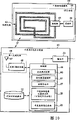
Fig. 1 is a sketch map, shows the population structure according to the position in examinee display system of first embodiment;
Fig. 2 is a block diagram, shows the structure that is arranged on the test capsule in the position in examinee display system;
Fig. 3 is a block diagram, shows the structure of magnetic field detector and the structure of outer surface information deriving device;
Fig. 4 is a block diagram, shows the structure of the relative position information let-off gear(stand) that comprises in the position in examinee display system;
Fig. 5 is a flow chart, is used to explain the operation of deriving outer surface information;
Fig. 6 is a sketch map, shows the example of outer surface information;
Fig. 7 is a flow chart, is used to explain the operation of derivation test capsule with respect to the relative position of outer surface;
Fig. 8 is a sketch map, is used to explain the derivation of test capsule with respect to the position of magnetic field detector;
Fig. 9 is a sketch map, shows the example of the image that is shown by display device;
Figure 10 is a sketch map, shows the structure of the outer surface sensor portion that is provided with in the position in examinee display system according to second embodiment and the structure of outer surface information deriving device;
Figure 11 is a sketch map, shows the structure of the outer surface sensor that is provided with in the position in examinee display system according to the 3rd embodiment and the structure of outer surface information deriving device;
Figure 12 is a sketch map, shows the structure of the outer surface information deriving device that is provided with in the position in examinee display system according to the 4th embodiment;
Figure 13 is a block diagram, shows the structure according to the capsule type endoscope in the position in examinee display system of the 5th embodiment;
Figure 14 is a block diagram, shows the structure of the relative position information let-off gear(stand) that is provided with in the position in examinee display system according to the 4th embodiment.
The specific embodiment
With reference to the accompanying drawings the preferred embodiments of the present invention are described.
Below will the position in examinee display system according to first embodiment be described.Position in examinee display system according to first embodiment comprises: position detector 3, display device 4 and portable recording medium 5.The outer surface information of the shape of the outer surface of the relevant subject 1 of position detector 3 derivation etc., and detect the relative position of test capsule 2 (example of subject introducing device) with respect to outer surface.Display device 4 shows by position detector 3 detected relative positions.Portable recording medium 5 is transmission information between position detector 3 and display device 4.
Fig. 2 is a sketch map, shows the structure of test capsule 2.As shown in Figure 2, test capsule 2 has: shell 11, and it has the capsule shape similar to the shell of capsule type endoscope; Permanent magnet 12, it is arranged in the shell 11; With filling component 13, be used to fill the inner surface of shell 11 and the space between the permanent magnet 12.
Shell 11 for example is made of biocompatible materials.Therefore, even test capsule 2 retained several days, can not produce injurious effects in subject 1 to live body subject 1 yet.
Permanent magnet 12 (example of magnetic field generating unit) is to have the permanent magnet that can be contained in the size in the shell 11, and produces the negligible static magnetic field of time fluctuation of magnetic field intensity.Replace permanent magnet 12, for example can use by providing coil that constant current forms static magnetic field etc. as the magnetic field generating unit.But be to use the advantage that permanent magnet 12 has does not need driving electric.
Can represent that by the static magnetic field that permanent magnet 12 produces these magnetic lines of force enter the S utmost point after externally advancing, as shown in Figure 2 from the N utmost point output of permanent magnet 12 by the magnetic line of force with closed curve shape.In this regard, although the direct of travel of the magnetic line of force has position dependence, can think by the intensity of the represented static magnetic field of the magnetic line of force only according to and test capsule 2 between distance determine.In other words, the permanent magnet 12 that is built in the test capsule 2 is very small dimensionally, thereby compares and can ignore with the distance between test capsule 2 and each the magnetic field detector 6a-6h.With this understanding, the proportion of utilization factor alpha is represented and the magnetic field intensity P of test capsule 2 at a distance of the position of r:
P=α/r
3 (1)
Detect the position of test capsule 2 based on relation by formula (1) expression according to the position in examinee display system of first embodiment.
The inner surface of filling component 13 filling shells 11 and the space between the permanent magnet 12 are with the position of fixed permanent magnet 12.Employing constitutes filling component 13 to the material (for example barium sulfate) of subject 1 no adverse effect.Because barium sulfate can be used as the contrast agent of X-ray examination, so, can also come the detection position by X-ray examination except by the magnetic force detection position of the following stated.Therefore, by two testing results are compared each other, detection position more accurately.But, notice that it is not necessary that filling component 13 uses barium sulfate, can use the materials with function that has arbitrarily as filling component.
Display device 4 is used to show the relative position information of the test capsule of being obtained by position detector 32, and based on the data show image that from portable recording medium 5, obtains.Particularly, display device 4 can be by the directly display device of display image such as CRT monitor, liquid crystal display, perhaps can be to some other medium (as printer) output images.
Can be connected to portable recording medium 5 in position detector 3 and the display device 4 or disassemble, and be configured to and under connection status, to export and recorded information.Particularly, during test capsule 2 moved in the body cavity of subject 1, portable recording medium 5 was inserted in the relative position information let-off gear(stand) 10 that comprises in the above-mentioned position detector 3 and the record information relevant with the position of test capsule 2.Afterwards, after test capsule 2 is discharged in subject 1, portable recording medium 5 is removed and is inserted into from relative position information let-off gear(stand) 10 in the display device 4, read recorded data with rear indicator 4.Portable recording medium 5 is swap data between relative position information let-off gear(stand) 10 and display device 4, thereby subject 1 can be free movable when test capsule 2 moves in subject 1, is preferred therefore.But, also relative position information let-off gear(stand) 10 and display device 4 can be carried out wired connection and without portable recording medium 5.
Then, below position detector 3 is described.As shown in fig. 1, position detector 3 comprises magnetic field detector 6a-6h, outer surface sensor 7, outer surface information deriving device 8 and relative position information let-off gear(stand) 10.Magnetic field detector 6a-6h detects the intensity of the static magnetic field that produced by test capsule 2.Outer surface sensor 7 is used to derive the outer surface information of the following stated.Outer surface information deriving device 8 is derived the outer surface information of subject 1 by the position of detecting outer surface sensor 7.Relative position information let-off gear(stand) 10 is derived the relative position of test capsule 2 with respect to subject 1 outer surface based on by the magnetic field intensity of magnetic field detector 6a-6h detection and the outer surface information that is derived by outer surface information deriving device 8.
As shown in fig. 1, magnetic field detector 6a-6h is arranged on the outer surface of subject 1, and the intensity of the static magnetic field that the permanent magnet 12 that comprises in the test capsule 2 is produced detects.Fig. 3 is a sketch map, shows the concrete structure of magnetic field detector 6 and the concrete structure of outer surface information deriving device 8.Magnetic field detector 6 comprises the magnetic field sensor 15 that is used to detect magnetic field, and comprises and be used to derive self outer surface sensor 7 with respect to the relative position of subject 1.The outer surface sensor 7 that is arranged in the magnetic field detector 6 has identical 26S Proteasome Structure and Function with the outer surface sensor 7 that is positioned at magnetic field detector 6 outsides.Below, with reference to Fig. 3 is concentrated these outer surface sensors 7 are described.
In first embodiment, outer surface sensor 7 has following function: outwards surface information let-off gear(stand) 8 sends and has the radio signal of given intensity so that outer surface information deriving device 8 can detect the position of outer surface sensor 7.Particularly, outer surface sensor 7 comprises second wireless part 16, is used for the radio signal that first wireless part 19 (as described below) that outside surface information let-off gear(stand) 8 comprises sends given intensity.Second wireless part 16 comprises: emitter 17 is used to produce and export given radio signal; With transmitting antenna 18, be used to launch radio signal from emitter 17 outputs.At each outer surface sensor 7, the frequency from the radio signal of second wireless part 16 output is set to have different values.The reason of doing like this is in order to receive from radio signal that each outer surface sensor 7 sends at first wireless part 19, determines that according to the difference of frequency the receiving intensity which outer surface sensor 7 has sent radio signal and radio signal has much.
The magnetic field sensor 15 of outer surface sensor 7 is used for detecting in the place of the magnetic field detector 6 of placement position detection device 3 intensity in the magnetic field that is caused by test capsule 2.Particularly, for example utilizing, magnetic resistance (MI) pick off constitutes magnetic field sensor 15.The MI pick off has and for example uses the feature of FeCoSiB amorphous line as the magnetosensitive medium.When high frequency electric being offered the sensitive medium of magnetic, the magnetic resistance that the MI pick off utilizes the sensitive medium of magnetic detects magnetic field intensity with the MI effect of external magnetic field significant change.Although can use the magnetic field sensor 15 with further feature, the MI pick off has the advantage that can detect magnetic field intensity with extra high sensitivity.Magnetic field sensor 15 detected magnetic field intensity information are outputed to relative position information let-off gear(stand) 10 and are used to derive the position of test capsule 2 with respect to magnetic field detector 6.
Then, below outer surface information deriving device 8 is described.Outer surface information deriving device 8 is used to derive the outer surface information of subject 1 and the outer surface information that is derived is outputed to relative position information let-off gear(stand) 10.Particularly, outer surface information deriving device 8 comprises first wireless part 19, control part 20, corresponding relation data base 22 and efferent 23.First wireless part 19 receives the radio signal of second wireless part, 16 transmissions that comprise from outer surface sensor 7.Control part 20 is derived outer surface information.When deriving the position of outer surface sensor 7, uses control part 20 corresponding relation data base 22.The outer surface information that efferent 23 is derived control part 20 outputs to relative position information let-off gear(stand) 10.
Control part 20 has following function, promptly the intensity based on the radio signal that is received by first wireless part 19 derives outer surface information deriving device 8 (more precisely, reception antenna 24) and outer surface sensor 7 (more precisely, transmitting antenna 18) distance between, and utilize the derivation result to derive outer surface information.Particularly, control part 20 comprise spectrum analysis portion 26, apart from leading-out portion 27, outer surface sensor position leading-out portion 28 and outer surface information generating unit 29.Spectrum analysis portion 26 analyzes the frequency of the radio signal that is received and detects intensity in each frequency component.Apart from leading-out portion 27 based on the receiving intensity that detects by spectrum analysis portion 26, derive and outer surface sensor 7 between distance.Outer surface sensor position leading-out portion 28 is derived the position of outer surface sensor 7 based on canned data among range information of being derived by distance leading-out portion 27 and the corresponding relation data base 22.Outer surface information generating unit 29 derives the outer surface information of subject 1 based on the position that is arranged on the outer surface sensor 7 on subject 1 outer surface.In this regard, term " outer surface information " refers to and comprises the information of the external surface shape of subject 1 at least being carried out the required data of imaging.In first embodiment, it refers to also comprise the information of magnetic field detector 6a-6h with respect to the positional information of the outer surface of subject 1.
In first embodiment, the part in a plurality of outer surface sensors 7 is built in the magnetic field detector 6, and is arranged to have the fixed position relation with magnetic field sensor 15.Therefore, outer surface sensor position leading-out portion 28 is derived the position of outer surface sensor 7, derives the position of magnetic field sensor 15 thus.In addition, derive the shape etc. of the outer surface of subject 1 based on the position of outer surface sensor 7.Therefore, derive the feasible position relation that can derive magnetic field sensor 15 in position that has the outer surface sensor 7 of fixed position relation with magnetic field sensor 15 with respect to the outer surface of subject 1.In this regard, the outer surface sensor position leading-out portion 28 among first embodiment concerns leading-out portion as the position, is used to derive the outer surface and the relation of the position between the magnetic field sensor 15 of subject 1.In other words, in first embodiment, derive the shape etc. of the outer surface of subject 1 by the position of deriving all outer surfaces pick off 7, derive the position of corresponding magnetic field detector 6a-6h thus simultaneously with respect to outer surface.This has just generated the external surface shape that comprises subject 1 and magnetic field detector 6a-6h with respect to the position of the outer surface outer surface information as information.
Corresponding relation data base 22 has following function, promptly stores the correspondence relationship information between the particular location of distance between a plurality of outer surface sensors 7 and the outer surface information deriving device 8 and outer surface sensor 7.The stored relation content can be arbitrarily in corresponding relation data base 22, as long as it has described the corresponding relation between distance and the position.
In first embodiment, pay close attention to the shift in position of each related in the posture change of subject 1 outer surface sensor 7 and the relation between the distance, corresponding relation data base 22 storage all outer surfaces pick offs 7 are from the distance of datum mark and the correspondence relationship information between their position, but not in a plurality of outer surface sensor 7 one is from the distance of first wireless part 19 (datum mark) and the corresponding relation between its position.
Below relative position information let-off gear(stand) 10 is described.With reference to Fig. 4, shown the structured flowchart of relative position information let-off gear(stand) 10.Relative position information let-off gear(stand) 10 comprises intensity comparing section 30, selector 31, apart from leading-out portion 32, outer surface information retaining section 33, capsule position calculation portion 34 and storage part 35.Intensity comparing section 30 compares the magnetic field intensity that is detected by the magnetic field sensor 15 that comprises among the magnetic field detector 6a-6h respectively.Selector 31 is based on the comparative result of being derived by intensity comparing section 30, and selection and output are from a part of testing result of magnetic field detector 6a-6h.Based on the magnetic field intensity of selecting by selector 31, derive the distance between test capsule 2 and the selected magnetic field detector 6 apart from leading-out portion 32.Outer surface information retaining section 33 keeps from the outer surface information of outer surface information leading-out portion 8 outputs.The outer surface information that capsule position calculation portion keeps in the distance of test capsule 2 and the outer surface information retaining section 33 based on the magnetic field detector 6a-6h that is derived by distance leading-out portion 32, the position of deriving test capsule 2 by given computing.The result of calculation and the outer surface information of storage part 35 storage capsule position calculation portions 34.
Be used for deriving by the distance between selector 31 selected magnetic field detectors 6 and the test capsule 2 apart from leading-out portion 32 according to magnetic field intensity by selector 31 inputs.Particularly, based on the magnetic field intensity of being imported, the distance between magnetic field detector 6 and the test capsule 2 is derived in the computing of expressing by execution formula (1) apart from leading-out portion 32.
Capsule position calculation portion 34 is used for carrying out given computing by the positional information that utilizes the magnetic field detector 6a-6h that the distance that derived by distance leading-out portion 32 and outer surface information retaining section 33 keep, and derives the position of test capsule 2 with respect to the outer surface of subject 1.Capsule position calculation portion 34 has derives test capsule 2 is also exported this derivation results subsequently to storage part 35 with respect to the position of the outer surface of subject 1 function.
Below the operation according to the position in examinee display system of first embodiment is described.Utilize outer surface information deriving device 8 to derive the outer surface information of the positional information that comprises magnetic field detector 6a-6h according to the position in examinee display system of first embodiment, and derive the position of test capsule 2 with respect to the outer surface of subject 1 based on the magnetic field intensity that position and the magnetic field detector 6a-6h of the magnetic field detector 6a-6h that is detected detected.Below, at first the process of outer surface information deriving device 8 derivation outer surface information describes, and the process that relative position information let-off gear(stand) 10 is derived the relative position of test capsule 2 describes afterwards.
With reference to Fig. 5, show a flow chart, be used to illustrate operation by the position of the performed derivation magnetic field detector 6a-6h of outer surface information deriving device 8.As shown in Figure 5, outer surface information deriving device 8 receives the radio signal (step S101) of second wireless part, 16 transmissions that comprise from each outer surface sensor 7 by first wireless part 19.Outer surface information deriving device 8 detects (step S102) by the frequency of analyzing the radio signal that sends from each outer surface sensor 7 to its intensity afterwards, and based on the intensity that is detected, by the distance (step S103) between distance leading-out portion 27 derivation outer surface sensors 7 and the datum mark (for example first wireless part 19).
Afterwards, outer surface information deriving device 8 with reference to canned data among the corresponding relation data base 22, is derived the position (step S104) of all outer surfaces pick off 7 with respect to datum mark based on the distance that is derived.At last, outer surface information deriving device 8 is based on the shape of the outer surface of the position calculation subject 1 of the outer surface sensor 7 of being derived etc., and generates outer surface information (step S105) by outer surface information generating unit 29.
Below the distance among the step S103 derived carry out brief description.Be arranged on second wireless part 16 in each outer surface sensor 7 (be included among the magnetic field detector 6a-6h or independent exist) and have function with radial transmitted radio signal.The intensity of the radio signal of sending from second wireless part 16 and the negative cube of propagation distance are proportional.By utilizing this relation,, derive the distance between datum mark and magnetic field detector or the self-existent outer surface sensor 7 apart from the receiving intensity of leading-out portion 27 based on the radio signal that is detected by spectrum analysis portion 26.
The outer surface information that in step S105, generates as described below.As mentioned above, magnetic field detector 6 is arranged on the outer surface of subject 1.Therefore, the positional information of the magnetic field detector 6a-6h that derives in step S104 indicates the position of a part of outer surface of subject 1.In first embodiment, couple together with the position of line magnetic field adjacent detector 6a-6h, generate three-dimensional confining surface, thereby derive the external surface shape of subject 1, and associate the outer surface information that generates by three-dimensional confining surface and each magnetic field detector 6a-6h that will derive.In this regard, can be applied to body templates by the outer surface information that will be generated and derive more detailed outer surface information.
Certainly, preferably, when generating three-dimensional confining surface, use the information of self-existent outer surface sensor 7.
With reference to Fig. 6, be presented at the sketch map of the example of the outer surface information that derives among the step S105 with showing vision.In first embodiment, outer surface information comprises the shape of outer surface of subject 1 and the positional information of the magnetic field detector 6a-6h on the outer surface.Therefore, if demonstrate to vision outer surface information, then as shown in Figure 6, demonstrate corresponding to the outside surface image 36 of the external surface shape of subject 1 and magnetic field detector image 37a, 37b, 37e and the 37f that corresponds respectively to magnetic field detector 6a, 6b, 6e and 6f.In step S105, as shown in Figure 6, generate outer surface information with visual means.The relative position that outer surface information is outputed to relative position information let-off gear(stand) 10 and is used to derive test capsule.
Below how relative position information let-off gear(stand) 10 is derived test capsule 2 relative position describe.With reference to Fig. 7, show a flow chart, be used to the relative position that illustrates how relative position information let-off gear(stand) 10 derives test capsule 2.As shown in Figure 7, at first, relative position information let-off gear(stand) 10 will be remained in the outer surface information retaining section 33 (step S201) by the outer surface information that outer surface information deriving device 8 is derived.Afterwards, the intensity of the static magnetic field that 10 pairs of permanent magnets 12 by comprising in the test capsule 2 that detected by magnetic field detector 6a-6h of relative position information let-off gear(stand) are produced detects (step S202), and, select magnetic field detector 6 (step S203) by selector 31 according to the intensity that is detected.
Afterwards, relative position information let-off gear(stand) 10 is derived the distance (step S204) between selected magnetic field detectors 6 and the test capsule 2, and derives the position (step S205) of test capsule 2 with respect to magnetic field detector 6 based on the position of distance that is derived and selected magnetic field detector 6.Relative position information let-off gear(stand) 10 subsequently by utilize in step S205, obtain with respect to the outer surface information that keeps in the positional information of magnetic field detector 6 and the outer surface information retaining section 33, derive the relative position (step S206) of test capsule 2 with respect to the outer surface of subject 1.
The operation of repeating step S201 in the S206 records the relative position information of test capsule 2 with respect to the outer surface of subject 1 in the portable recording medium 5 till test capsule 2 is discharged to outside the subject 1 simultaneously at every turn.
Below carry out brief description to deriving test capsule 2 among the step S205 with respect to the process of the position of magnetic field detector 6.With reference to Fig. 8, show a sketch map, be used to illustrate of the operation of derivation test capsule 2 with respect to the position of magnetic field detector 6.In the following description, suppose in above-mentioned steps S104, to have derived the position of all magnetic field detector 6a-6h and these positions as shown in Figure 8 by coordinate (xa, ya, za)-(xh, yh, zh) expression.In addition, suppose in step S203, to have selected magnetic field detector 6e, 6f and 6h and in step S204, derived magnetic field detector 6e, 6f and 6h and test capsule 2 between apart from r1, r2 and r3.
With this understanding, based on expression formula shown below derive test capsule 2 position coordinates (x, y, z).In other words, based on the coordinate of magnetic field detector 6e, 6f and 6h with apart from r1, r2 and r3, following relational expression is set up:
(x-xe)
2+(y-ye)
2+(z-ze)
2=r1
2 (2)
(x-xf)
2+(y-yf)
2+(z-zf)
2=r2
2 (3)
(x-xh)
2+(y-yh)
2+(z-zh)
2=r3
2 (4)
In formula (2)-(4), in step S104 and S204, derived the occurrence of xe, xf, xh, ye, yf, yh, ze, zf, zh and r1, r2, r3 respectively.Therefore, in step S205, in formula (2)-(4), there are three unknown number x, y and z.The simultaneous equations of through type (2)-(4) solve the derive position coordinates of test capsule 2 of unknown number.
Below the derivation test capsule of carrying out among the step S206 2 is carried out brief description with respect to the process of the relative position of the outer surface of subject 1.As mentioned above, generate outer surface information by the processing among the step S101-S106, this outer surface information comprises the information of external surface shape and the magnetic field detector 6a-6h information with respect to the position of outer surface.On the other hand, in step S205, derive magnetic field detector and the relation of the position between the test capsule 2 from magnetic field detector 6a-6h, selected.Therefore, the outer surface and the relation of the position between the test capsule 2 of subject 1 have been determined uniquely by the positional information of magnetic field detector 6a-6h.Correspondingly, can utilize this information to derive the relative position of test capsule 2 with respect to the outer surface of subject 1.
Fig. 9 is a sketch map, shows based on subject 1 outer surface of above algorithm derivation and the relative position relation between the test capsule 2.In step S206, generate the information that shows with visual means among Fig. 9.By obtain the information that shows with visual means among Fig. 9 via portable recording medium 5, display device 4 demonstrates the relative position of test capsule 2 with respect to subject 1 outer surface.Particularly, as shown in Figure 9, display device 4 be presented at the outside surface image 36 that comprises in the outer surface information that derives among the step S101-S105 and with step S206 in the corresponding capsule image 39 of relative position of the test capsule 2 that derives.These pictorial display demonstrate the relative position of test capsule 2 with respect to the outer surface of subject 1 thus on the screen of display device 4.
Then, below the advantage according to the position in examinee display system of first embodiment is described.At first, in the position in examinee display system according to first embodiment, the position that shows test capsule 2 is with corresponding to the zone in the outer surface of the subject 1 that has imported test capsule 2.Therefore, utilize the position in examinee display system according to first embodiment, doctor, nurse etc. can grasp the relative position of test capsule 2 with respect to the outer surface of subject 1 intuitively.Thus, doctor, nurse etc. not only can identify the position coordinates of test capsule 2, and can determine easily test capsule 2 is positioned at around which interior zone of subject 1.Especially, doctor, nurse etc. possess the knowledge which organ to be arranged in which zone of subject 1 such as usually.Therefore, by showing the position of test capsule 2, can easily obtain the information of just passing through which organ in the subject 1 such as test capsule 2 with respect to the outer surface of subject 1.Therefore, the position in examinee display system according to first embodiment has the following advantages the very fast organ of diagnosing out test capsule 2 to be difficult to pass through when promptly doctor, nurse etc. can reduce in the translational speed of test capsule 2.
In addition, in position in examinee display system, generate outer surface information during each use test capsule 2 as the information such as shape of the outer surface of subject 1 according to first embodiment.Therefore, this position in examinee display system has the following advantages, promptly can obtain the corresponding outside surface image of physique difference that the individual variation (for example sex, age, race etc.) with subject 1 is caused, thereby obtain the relative position of more accurate test capsule 2.
In addition, position in examinee display system according to first embodiment has following feature, the i.e. position of repeatedly deriving outer surface information and deriving test capsule 2, till test capsule 2 is discharged from, and derive test capsule 2 each relative position during this period with respect to outer surface one by one.Therefore, even because the variation of the posture of subject 1 etc. makes the absolute position of test capsule 2 that discontinuous variation take place, also can the outside surface image of the subject 1 that changes take place by knowing posture etc., easily grasped test capsule 2 in tested intravital position.
Position in examinee display system according to first embodiment has permanent magnet 12 in test capsule 2, and have a following feature, promptly the intensity based on the detected static magnetic field that is produced by permanent magnet 12 detects the position of test capsule 2 in subject 1.Certainly, electromagnetic wave can be utilized and non-magnetic field detects the position of test capsule.But if use electromagnetic wave, then the ratio dielectric constant of organ or electrical conductivity can change, and the attenuation rate of radio signal strength changes a lot according to the type that constitutes thing thus.For example, if liver or blood vessel, then radio signal is absorbed in a large number, thereby attenuation rate increases, and this has just hindered the detection of accurate position.Different with electromagnetic wave, static magnetic field has following feature, and promptly intensity is independent of the variation of physical parameter (such as ratio dielectric constant and the pcrmeability in the propagation zone) and the decay of uniqueness ground basically, has therefore advantageously realized the represented relation of formula (1).Therefore, static magnetic field has the following advantages: even when inside of human body detects the position in the place have the organ that physical parameter differs from one another, compare the position probing that also can realize high accuracy with the position probing of using electromagnetic wave etc.
As the advantage of static magnetic field, when importing test capsule 2 in the subject 1, reduced the burden of subject 1.In other words, for above-mentioned reasons, have according to the position in examinee display system of first embodiment and to suppress because the advantage that the detection position accuracy that difference caused of the surrounding of test capsule 2 descends.Therefore, for example, when importing test capsule 2 in the subject, needn't limit (for example essential restriction is eaten or drunk in other method of testing).Therefore, subject 1 can be crossed normal life at the test period that carries out test capsule 2, has therefore reduced the burden at test period subject 1.
In addition, comprise outer surface information deriving device 8, the position of the magnetic field detector 6a-6h that its intensity that is used to derive the static magnetic field that test capsule 2 is produced detects according to the position in examinee display system of first embodiment.As mentioned above, magnetic field detector 6a-6h is arranged on the outer surface of subject 1.Therefore, because position deviation that produces along with the time or the position deviation that causes because of the posture change of subject 1 etc., the position separately of magnetic field detector 6a-6h changes with respect to subject 1.Therefore, the position that outer surface information deriving device 8 has been derived the position of magnetic field detector 6a-6h veritably and utilized the position derived to derive test capsule 2, the position that can irrespectively derive test capsule 2 exactly with any variation of the posture of subject 1 thus.
In addition, use radio signal to derive the position of magnetic field detector 6a-6h, and derive these positions in the mode different with the static magnetic field that is used to derive test capsule 2 positions according to the position in examinee display system of first embodiment.The transmission of radio signal and the transmission of static magnetic field are separate, between them without any interference.Therefore, the position in examinee display system according to first embodiment can prevent that the position derivation that derive test capsule 2 position of magnetic field detector 6a-6h from having a negative impact.Therefore, the position in examinee display system according to first embodiment has the following advantages: even after importing test capsule 2 in the subject 1, also can derive the position of magnetic field detector 6a-6h under the situation of the position derivation that does not influence test capsule 2.
Though use radio signal to derive the position of magnetic field detector 6a-6h, different with the position derivation of test capsule, the variation of the attenuation rate that is caused by the internal of subject 1 etc. can not produce any influence basically.In other words, situation about moving in the wide region from the esophagus to the large intestine with test capsule is different, although the posture change of subject 1 can cause the change in location of magnetic field detector 6a-6h, its position range does not have much.In addition, the internal between magnetic field detector 6a-6h and the outer surface information deriving device 8 can be along with these change in location significant change.For example, the structure that the intensity of radio signal compares when adopting the intensity of the radio signal sent from magnetic field detector 6a-6h under the original state and detection position can reduce the mistake of the derivation position that caused by the attenuation rate difference.
Below be to explanation according to the position in examinee display system of second embodiment.Position in examinee display system according to second embodiment comprises the RFID label as second wireless part that comprises in the outer surface sensor portion, thereby can identify the transmission source of the radio signal that a plurality of outer surface sensors 7 from the outer surface that is arranged on subject 1 send.Except outer surface sensor portion and outer surface information deriving device, have the structure identical according to the position in examinee display system of second embodiment, therefore following diagram and the explanation that will omit same section with first embodiment.
With reference to Figure 10, show the sketch map of the concrete structure of the concrete structure of the outer surface sensor portion that comprises in the position in examinee display system according to second embodiment and outer surface information deriving device.As shown in Figure 10, outer surface sensor portion 40 comprises the RFID label 41 as second wireless part.RFID label 41 specifically comprises: loop antenna 42; Control part 43, it is connected to loop aerial 42; With storage part 44, it has based on the instruction from control part 43 exports the function of stored information at least to control part 43.
Loop aerial 42 is used to receive send and the radio signal that comprise control signal and power supply signal from outer surface information deriving device side.Particularly, loop aerial 42 has radio signal that reception sends from outer surface information deriving device 45 sides and the function that this signal is outputed to control part 43.On the other hand, control part 43 extracts power supply signal and control signal from radio signal, generates driving power based on power supply signal, and based on control signal indication storage part 44 output institute canned datas.In response to this, storage part 44 stores respectively the mutually different identifying information for a plurality of outer surface sensors 7, and to control part 43 these identifying informations of output.Control part 43 generates and comprises the given radio signal of the identifying information that is obtained and by loop aerial 42 this signal is sent to outer surface information deriving device 45.
Corresponding to being provided with RFID label 41 in outer surface sensor portion 40, outer surface information deriving device 45 comprises transmit/receive antenna 47 and emission/receiving circuit 48 and comprise identification part, transmission source 50 and receiving intensity test section 51 in control part 49 in first wireless part 46.For providing new sending function to be based on, first wireless part 46 sends radio signal to drive the needs of RFID label.Identification part, transmission source 50 in the control part 49 is used for decoding by the identifying information that the radio signal of sending from RFID label 41 is comprised, and has sent the outer surface sensor 7 of radio signal with identification.Receiving intensity test section 51 is used for the receiving intensity of the radio signal that identifies the transmission source is detected.
In this way, if RFID label 41 is used as second wireless part, then can utilize the identifying information that comprises in the radio signal to identify the transmission source.Therefore, the position in examinee display system according to second embodiment has the following advantages: make system have simple structure and different frequencies need not be set for the radio signal of sending from outer surface sensor 7.
Below be to explanation according to the position in examinee display system of the 3rd embodiment.Position in examinee display system according to the 3rd embodiment has a plurality of reference positions, preferably has three or more positions, and this system comprises reference sensor, and it has a plurality of reception antennas corresponding to these reference positions.In position in examinee display system according to the 3rd embodiment, identical among the composed component except that reference sensor and first and second embodiment.Therefore, below will omit their diagram and explanation.
With reference to Figure 11, show block diagram according to the 26S Proteasome Structure and Function of the position in examinee display system of the 3rd embodiment.As shown in Figure 11, benchmark outer surface information deriving device 52 comprises the reception antenna 53a-53c that is provided with corresponding to a plurality of reference positions and the selector 55 between reception antenna 53a-53c and the receiving circuit 25.Control part 56 comprises position leading-out portion 57, and it is used for the basis algorithm different with the algorithm of the outer surface sensor position leading-out portion 28 of first and second embodiment derives the position.
Below will derive operation and carry out brief description the position of the outer surface sensor among the 3rd embodiment 7.In the 3rd embodiment, receive the radio signal of sending from outer surface sensor 7 by reception antenna 53a-53c, and selector 55 is exported the radio signal that is received by reception antenna 53a-53c successively to receiving circuit 25.After each radio signal having been carried out decoding or other processing, receiving circuit 25 is to control part 56 these radio signals of output.In control part 56, comprise apart from leading-out portion 27 derive between a plurality of reference positions and the outer surface sensor 7 apart from ra, rb and rc.
Then, below will the operation of position leading-out portion 57 be described.Position leading-out portion 57 has been grasped the particular location coordinate corresponding to a plurality of reference positions of reception antenna 53a-53c in advance, and based on the position coordinates of reception antenna 53a-53c and the position apart from ra, rb and rc derivation outer surface sensor 7 between reception antenna 53a-53c and the outer surface sensor 7.Particularly, suppose that the position coordinates of reception antenna 53a-53c is (x1, y1, z1), (x2, y2, z2) and (x3, y3, z3), and the position coordinates of the magnetic field detector 6 that will derive be (z), then following formula is set up for x, y:
(x-x1)
2+(y-y1)
2+(z-z1)
2=ra
2 (5)
(x-x2)
2+(y-y2)
2+(z-z2)
2=rb
2 (6)
(x-x3)
2+(y-y3)
2+(z-z3)
2=rc
2 (7)
Because the unknown number in formula (5)-(7) is x, therefore y and z pass through the particular location that outer surface sensor 7 is derived in solving equation (5)-(7).
By deriving the position of outer surface sensor 7 in this way, can under the situation that does not have the corresponding relation data base, derive the position of outer surface sensor 7 according to the position in examinee display system of the 3rd embodiment.In addition, benchmark outer surface information deriving device 52 has following function: only derive the position according to the radio signal that is received by a plurality of reception antenna 53a-53c under the situation of the corresponding relation that does not have to derive in advance in a conventional manner.Therefore, can derive the position of outer surface sensor 7 more accurately corresponding to individual variation of the action of subject 1 etc.Therefore, this position in examinee display system has can derive the advantage of the relative position of test capsule 2 with high accuracy.
Below the position in examinee display system according to the 4th embodiment is described.In the position in examinee display system according to the 4th embodiment, the outer surface information deriving device not only detects the intensity of the radio signal of sending from outer surface sensor 7, and detects the direction in transmission source.In position in examinee display system according to the 4th embodiment, identical among the composed component beyond the reference sensor and first and second embodiment.Therefore, below omit their diagram and explanation.
With reference to Figure 12, show structured flowchart according to the position in examinee display system of the 4th embodiment.As shown in Figure 12, outer surface information deriving device 58 comprise have array antenna 60 (but not the reception antenna 24 among first embodiment) first wireless part 59, have new control part 61, and efferent 23 towards adjusting portion 62.
When receiving from radio signal that outer surface sensor 7 sends, array antenna 60 also detects each the outer surface sensor 7 residing direction as the transmission source.Particularly, array antenna 60 comprises a plurality of reception antennas and the signal processing apparatus of for example arranging in the two-dimensional matrix mode, this signal processing apparatus is used for by the radio signal that reception antenna received is amplified, postponed or other processing, with assigned direction (hereinafter referred to as " and towards ") provide high receiving sensitivity to whole array antenna 60.In the control part 61 towards adjusting portion 62 have in given range change array antenna 60 towards function.
Below the process of the position of magnetic field detector 6 is derived in explanation in according to the position in examinee display system of the 4th embodiment.At first, by regulate towards adjusting portion 62 array antennas 60 towards in, outer surface information deriving device 58 search array antennas 60 can receive the direction of the radio signal of sending from outer surface sensor 7.Afterwards, when by towards adjusting portion 62 control when consistent with outer surface sensor 7 residing directions, receive radio signals and detect receiving intensity by array antenna 60 by the radio signal of receiving intensity test section 51 receptions.Simultaneously, derive the reference position of placement array antenna 60 and the distance between the outer surface sensor 7 apart from leading-out portion 27 based on the receiving intensity that is detected, and subsequently this range information is sent to outer surface sensor position leading-out portion 28.
Orientation information when on the other hand, outer surface sensor position leading-out portion 28 receives this radio signal from obtaining towards adjusting portion 62.That is to say, reception from the radio signal of magnetic field detector 6 towards consistent with outer surface sensor 7 residing directions, so outer surface sensor position leading-out portion 28 based on this towards deriving the position of outer surface sensor 7 with the distance that is derived by distance leading-out portion 27.When the position of the magnetic field detector 6 of in this process, being derived with three-dimensional polar coordinate representation, outer surface sensor position leading-out portion 28 can convert thereof into three-dimensional cartesian coordinate system and by efferent 23 with its output.
In position in examinee display system, derive the position of outer surface sensor 7 by distance between direct detection reference position and the outer surface sensor 7 and outer surface sensor 7 residing directions according to the 4th embodiment.Therefore, according to the position in examinee display system of the 4th embodiment not the calculating of needs complexity derive the position of outer surface sensor 7.
Below the position in examinee display system according to the 5th embodiment is described.In position in examinee display system, use capsule type endoscope to have the function of the radio signal that processing sends as subject introducing device and relative position information let-off gear(stand) from capsule type endoscope according to the 5th embodiment.
Figure 13 is a block diagram, shows the structure as the employed capsule type endoscope of example of the subject introducing device among the 5th embodiment.Figure 14 is a block diagram, shows the structure of the relative position information let-off gear(stand) that comprises in the position in examinee display system.In the 5th embodiment, identical except among the composed component capsule type endoscope and the relative position information let-off gear(stand) and first to fourth embodiment.Therefore, below omit their diagram and explanation.
As shown in Figure 13, capsule type endoscope 65 comprises: permanent magnet 12; LED66 illuminates the Lighting Division of imaging area during as the image in taking subject 1; Led drive circuit 67 is used to control the driving condition of LED66; CCD68 is as the imaging portion of the reflected light image of taking the regional reflex of illuminating from LED66; And CCD drive circuit 69, be used to control the driving condition of CCD68.LED66, led drive circuit 67, CCD68 and CCD drive circuit 69 integrally are used as in-subject information acquisition unit 70.
Utilize these features, when importing capsule type endoscope 65 in the subject 1, capsule type endoscope 65 obtains the view data at the tested position of being illuminated by LED66 by CCD68.In transtation mission circuit 71, convert the view data of being obtained to the RF signal and also send to the outside by transmitting antenna portion 72 subsequently.
In addition, capsule type endoscope 65 has the function of the radio signal that reception sends from relative position information let-off gear(stand) 100 sides.Particularly, capsule type endoscope 65 comprises: reception antenna portion 74 is used to receive the radio signal of sending from relative position information let-off gear(stand) 100 sides; Split circuit 75 is used for isolating power supply signal from the radio signal that reception antenna portion 74 receives.In addition, capsule type endoscope 65 comprises: electric power regenerative circuit 76 is used for from the isolated power supply signal electric power of regenerating; Booster circuit 77 is used for regenerated electric power is boosted; With electric storage means 78, be used to store the electric power after boosting.In addition, capsule type endoscope 65 comprises control information testing circuit 79, is used for detecting from the composition that has separated with power supply signal at split circuit 75 content of control information signal, and the control information signal that is detected is outputed to system, control circuit 73.
Utilize these features, at first, capsule type endoscope 65 receives the radio signal of sending from relative position information let-off gear(stand) 100 sides at reception antenna portion 74 places, and isolates power supply signal and control information signal by split circuit 75 from the radio signal that is received.
75 isolated control information signals of split circuit are input to system, control circuit 73 by control information testing circuit 79.System, control circuit 73 is based on the driving condition of mobile status information control LED66, CCD68 and transtation mission circuit 71.On the other hand, electric power regenerative circuit 76 is power supply signal regeneration electric power, and booster circuit 77 boosts to regenerated electric power the current potential that is suitable for electric storage means 78.Afterwards with electrical power storage in electric storage means 78.
Subsequently, with reference to Figure 14 the position detector among this embodiment is described.As shown in Figure 14, except the feature of first to the 4th embodiment, position detector also comprises reception antenna A1-An and power supply antenna B1-Bm, and has the receptor function of the radio signal that reception sends from capsule type endoscope 65 and the transmitter function that sends given signal with wireless mode to capsule type endoscope 65.
At first, relative position information let-off gear(stand) 100 has the function of receptor, is used to receive the view data in the subject 1 that sends with wireless mode from capsule type endoscope 65.Particularly, relative position information let-off gear(stand) 100 comprises: receiving circuit 82, be used for given processing, and from radio signal, extract the view data of obtaining by capsule type endoscope 65 by radio signal execution such as the demodulation that selected reception antenna received; Signal processing circuit 83 is used to carry out the required processing of output image data; And storage part 84, be used to write down through the view data of Flame Image Process etc.
Storage part 84 has the function of storing image data, and has the function of storage by the positional information of the capsule type endoscope 65 of capsule position calculation portion 34 derivation.Utilize these features, display device 4 can show the image of subject 1 and the image taking position in the subject 1 simultaneously.
In addition, relative position information let-off gear(stand) 100 has the function of emitter, is used to generate the power supply signal that will send to capsule type endoscope 65 and control information signal and these signals are outputed to power supply antenna B1-Bm.Particularly, as shown in Figure 14, relative position information let-off gear(stand) 100 comprises: agitator 85, and it has function that generates power supply signal and the function of regulating frequency of oscillation; Control information input part 86 is used to generate the control information signal of the following stated; Supercircuit 87 is used for power supply signal and control information signal are made up; And amplifier circuit 88, be used to amplify the intensity of composite signal.Signal after amplifier circuit 88 amplifications is sent to power supply antenna B1-Bm and subsequently this signal sent to capsule type endoscope 65.Relative position information let-off gear(stand) 100 comprises power supply unit 89, and power supply unit 89 comprises given electric storage means or AC adapter, and the power supply that the composed component of relative position information let-off gear(stand) 100 use power supply unit 89 is provided is as drive energy.
Utilize above feature, in position in examinee display system according to the 5th embodiment, display device 4 not only can show the relative position (the subject introducing device is with respect to a kind of form of subject 1 outer surface) of capsule type endoscope 65, and can show the tested in-vivo image of being taken by capsule type endoscope 65 at shown relative position place.Therefore, this position in examinee display system has the following advantages, be doctor, nurse etc. can easily know taken tested in-vivo image with respect to the relative position of subject 1 outer surface at which, what organ what can easily determine on captured image imaging thus is.
Although describe the present invention according to above-mentioned first to the 5th embodiment, the present invention is not limited to these embodiment.On the contrary, those skilled in the art can expect various embodiment, modified example and application examples.For example, although the visual information shown in display device 4 displayed map 9 in first embodiment, but needn't be interpreted as being limited to this display mode, display device 4 for example can show character information etc., as long as it demonstrates the outer surface of subject 1 and the relative position between test capsule 2 or other subject introducing device.
Although the subject introducing device comprises capsule type endoscope and test capsule, it is not limited to this.
In addition, in first to the 5th embodiment, thereby constitute position detector respectively and display device 4 is independently of one another as shown in fig. 1.But, will the present invention not be interpreted as being limited to this structure, position detector can form as one with display device 4.In addition, in first to the 5th embodiment, second wireless part is arranged in the outer surface information deriving device, and constitutes the outer surface information deriving device respectively and the relative position information let-off gear(stand) makes it independently of one another.But it only is for convenience of explanation that these features are provided, and will the present invention not be interpreted as being limited to these features.For example, the relative position information let-off gear(stand) can form as one with the outer surface information deriving device, thereby and second wireless part and outer surface information deriving device constitute discriminably independently of one another.In addition, for example in an embodiment for ease of explanation, with corresponding relation data base 22, outer surface information retaining section 33 and storage part 35 as independent also composed component independently.Resembling these composed components with common function can form as one.
In addition, in first to the 5th embodiment, some outer surface sensors 7 are built in respectively among the magnetic field detector 6a-6h, and other outer surface sensor 7 is arranged on the outer surface of subject 1 independently.But, adopt the reason of this feature to be, although as the quantity of the required magnetic field sensor 15 in the position of detecting test capsule 2 grades, three magnetic field sensors 15 are just much of that theoretically, need to increase the quantity of outer surface sensor 7 to obtain more accurate outer surface information.Therefore, for example, a plurality of magnetic field detectors 6 can be set, and each magnetic field detector 6 all has the magnetic field sensor 15 with outer surface sensor 7 integrated formations, perhaps can only utilize outer surface sensor built-in among the magnetic field detector 6a-6h 7 to derive outer surface information simply.
In addition, for simpler setting, can use existing outer surface information to derive and show the relative position of subject introducing device.First feature of the present invention is to show the relative position of subject introducing device with respect to outer surface.Therefore, the means that are used to carry out this demonstration can be the modes different with the foregoing description.
In addition, in the 5th embodiment, be illustrated as the in-subject information acquisition unit 70 of Lighting Division as imaging portion and LED66 having CCD68.The in-subject information acquisition unit can have the pH that obtains in the subject 1 or the function of temperature information.In addition, as the feature of subject introducing device, can obtain the ultrasonography in the subject 1 with agitator.In addition, the present invention can comprise the feature of obtaining polytype information from tested intravital above-mentioned information.
Although to thinking that the preferred embodiments of the present invention show and illustrate,, should be appreciated that, under the situation that does not deviate from spirit of the present invention, can carry out various modifications and changes from form or details.Therefore, the present invention can not be defined as describe and illustrated strict form, but constitute all modifications of containing the scope that can fall into claims.
Claims (13)
1. a position in examinee display system is used to show import in the subject and the position of the subject introducing device that moves therein,
It is characterized in that described position in examinee display system comprises:
Position detecting device is used to detect the relative position of described subject introducing device with respect to the outer surface of described subject; And
Display device is used for the testing result based on described position detecting device, shows the relative position of described subject introducing device with respect to described outer surface, wherein
Described position detecting device comprises,
Magnetic field sensor is used for detecting the intensity of the static magnetic field that the magnetic field generating unit that comprised by described subject introducing device produced;
Be arranged on a plurality of outer surface sensors on the outer surface of described subject;
Outer surface information leading-out portion is used for deriving based on the position of described outer surface sensor the outer surface information of described subject;
The position concerns leading-out portion, is used to derive the outer surface and the relation of the position between the described magnetic field sensor of described subject; And
The relative position information leading-out portion, be used for deriving the relative position information of described subject introducing device with respect to described subject outer surface based on the relation of the position between described subject outer surface of being derived and the described magnetic field sensor and by the magnetic field intensity that described magnetic field sensor detected.
2. position in examinee display system according to claim 1, wherein said display device show described subject outside surface image and with respect to described outside surface image be arranged on the corresponding zone of the relative position of described subject introducing device in the image of described subject introducing device.
3. position in examinee display system according to claim 2, wherein
In described magnetic field sensor and the described outer surface sensor at least one has fixed position relation; And
Described position concerns that leading-out portion based on having the position of the described outer surface sensor of fixed position relation with described magnetic field sensor, derives the outer surface and the relation of the position between the described magnetic field sensor of described subject.
4. position in examinee display system according to claim 2 further comprises first wireless part that is arranged on the place, reference position, wherein
Described a plurality of outer surface sensor have respectively be used for to or from second wireless part of described first wireless part transmission radio signal; And
Described outer surface information leading-out portion comprises:
Apart from leading-out portion, be used for the radio signal transmission between described first wireless part and described second wireless part, based at least one receiving intensity in described first wireless part and described second wireless part, derive the distance between described reference position and the described outer surface sensor;
Outer surface sensor position leading-out portion is used for based on the position of being derived described outer surface sensor by the described distance that derives apart from leading-out portion; And
Outer surface information generating unit is used for generating based on the position of being derived by described outer surface sensor position leading-out portion the outer surface information of described subject.
5. position in examinee display system according to claim 4, wherein
Described a plurality of second wireless part sends the radio signal of the frequency that differs from one another; And
Described outer surface information leading-out portion further comprises spectrum analysis portion, is used for discerning by the frequency analysis of radio signal that described first wireless part is received the transmission source of the radio signal that is received.
6. position in examinee display system according to claim 4, wherein
Described a plurality of second wireless part respectively comprises the RFID label that stores the identifying information that differs from one another; And
Described outer surface information leading-out portion further comprises identification part, transmission source, is used for discerning based on the described identifying information that the radio signal that is received by described first wireless part comprises the transmission source of the radio signal that is received.
7. position in examinee display system according to claim 4, wherein
Described outer surface information leading-out portion further comprises the location information data storehouse, and it stores the correspondence relationship information between the position of each distance between described a plurality of outer surface sensor and the described reference position and described outer surface sensor; And
Described outer surface sensor position leading-out portion is derived and the described corresponding position of distance of deriving apart from leading-out portion according to canned data in the described location information data storehouse.
8. position in examinee display system according to claim 4, wherein
Be provided with a plurality of described first wireless parts; And
Distance between the leading-out portion derivation of described outer surface sensor position and corresponding a plurality of reference positions of each first wireless part and the described outer surface sensor, and based on the position apart from the described outer surface sensor of derivation of being derived.
9. position in examinee display system according to claim 4, wherein
Described outer surface sensor position leading-out portion further comprises:
Towards adjusting portion, be used for to use described first wireless part send described radio signal towards regulating; And
Towards determination portion, be used for determining producing the direction of high receiving intensity in radio signal transmission with described second wireless part; And
Described outer surface sensor position leading-out portion based on by the described distance that derives apart from leading-out portion and by described towards determination portion determined towards, derive the position of described outer surface sensor.
10. position in examinee display system according to claim 1, wherein
Described subject introducing device further comprises:
The in-subject information acquisition unit is used to obtain in-subject information; And
Radio transmitting portion is used for sending the described in-subject information that is obtained by described in-subject information acquisition unit with wireless mode,
Described position detecting device further comprises radio reception portion, is used to receive the radio signal of sending from described radio transmitting portion that comprises described in-subject information; And
Described display device further shows the content of the radio signal that is received by described radio reception portion.
11. position in examinee display system according to claim 10, wherein
Described in-subject information acquisition unit comprises:
Lighting Division is used to illuminate the inside of described subject; And
Image-generating unit is used to obtain the described tested intravital image that is illuminated by described Lighting Division; And
Described radio transmitting portion sends and comprises the radio signal of utilizing the image information that described image-generating unit photographic images obtained.
12. a position in examinee display system comprises a plurality of pick offs, is used for the position that imports to tested intravital subject introducing device is detected, described a plurality of pick offs are arranged on the outer surface of described subject,
It is characterized in that described position in examinee display system further comprises:
A plurality of pick offs with magnetic field sensor unit, this magnetic field sensor unit detect the intensity that the magnetic field that is had by described subject introducing device forms the magnetostatic field that the unit forms; The radio signal generation unit, it is built at least a portion of described a plurality of pick offs; Accountant is used for calculating the outer surface of described subject by receiving the radio signal that is generated by described radio signal generation unit;
The position concerns let-off gear(stand), and it derives the outer surface and the relation of the position between the described magnetic field sensor unit of described subject; And
The relative position information lead-out unit, it is according to the outer surface and the relation of the position between the described magnetic field sensor unit of the described subject of being derived, and, derive the relative position information of described subject introducing device with respect to the outer surface of described subject by the detected magnetic field intensity of described magnetic field sensor unit.
13. position in examinee display system, it has first sensor, this first sensor comprises magnetic field sensor, and this magnetic field sensor detects by importing to magnetic field that tested intravital subject introducing device had and forms the intensity of the magnetostatic field that the unit forms
It is characterized in that described position in examinee display system comprises:
A plurality of second pick offs are used to detect the position of the outer surface of described subject, and described a plurality of second pick offs are arranged on the outer surface of described subject;
The position concerns lead-out unit, and it derives the position relation between described second pick off and the described first sensor;
The relative position information lead-out unit, it concerns according to the position between described second pick off of being derived and the described first sensor, and, derive the relative position information of described subject introducing device with respect to the outer surface of described subject by the detected magnetic field intensity of described magnetic field sensor unit; And
Display device is used to show that the outer surface of described subject and the position between the described subject introducing device concern.
Applications Claiming Priority (2)
| Application Number | Priority Date | Filing Date | Title |
|---|---|---|---|
| JP2004113191A JP4520198B2 (en) | 2004-04-07 | 2004-04-07 | In-subject position display system |
| JP2004113191 | 2004-04-07 |
Publications (2)
| Publication Number | Publication Date |
|---|---|
| CN1679444A CN1679444A (en) | 2005-10-12 |
| CN100353916C true CN100353916C (en) | 2007-12-12 |
Family
ID=35066508
Family Applications (1)
| Application Number | Title | Priority Date | Filing Date |
|---|---|---|---|
| CNB2005100650621A Expired - Fee Related CN100353916C (en) | 2004-04-07 | 2005-04-07 | In vivo position display system |
Country Status (3)
| Country | Link |
|---|---|
| US (1) | US7603160B2 (en) |
| JP (1) | JP4520198B2 (en) |
| CN (1) | CN100353916C (en) |
Families Citing this family (88)
| Publication number | Priority date | Publication date | Assignee | Title |
|---|---|---|---|---|
| US8836513B2 (en) | 2006-04-28 | 2014-09-16 | Proteus Digital Health, Inc. | Communication system incorporated in an ingestible product |
| US8912908B2 (en) | 2005-04-28 | 2014-12-16 | Proteus Digital Health, Inc. | Communication system with remote activation |
| US9198608B2 (en) | 2005-04-28 | 2015-12-01 | Proteus Digital Health, Inc. | Communication system incorporated in a container |
| US8730031B2 (en) | 2005-04-28 | 2014-05-20 | Proteus Digital Health, Inc. | Communication system using an implantable device |
| CN101287411B (en) | 2005-04-28 | 2013-03-06 | 普罗秋斯生物医学公司 | Pharma-informatics system |
| US8802183B2 (en) | 2005-04-28 | 2014-08-12 | Proteus Digital Health, Inc. | Communication system with enhanced partial power source and method of manufacturing same |
| AU2006251454A1 (en) * | 2005-05-24 | 2006-11-30 | Responsif Gmbh | Method for producing virus-type particles containing an active substance |
| US8547248B2 (en) * | 2005-09-01 | 2013-10-01 | Proteus Digital Health, Inc. | Implantable zero-wire communications system |
| CA2650920C (en) | 2006-05-02 | 2016-10-18 | Proteus Biomedical, Inc. | Patient customized therapeutic regimens |
| DE102006029122A1 (en) * | 2006-06-22 | 2007-12-27 | Amedo Gmbh | System for determining the position of a medical instrument |
| US20080020037A1 (en) * | 2006-07-11 | 2008-01-24 | Robertson Timothy L | Acoustic Pharma-Informatics System |
| JP5084200B2 (en) * | 2006-08-29 | 2012-11-28 | オリンパスメディカルシステムズ株式会社 | Capsule guidance system |
| EP2087589B1 (en) * | 2006-10-17 | 2011-11-23 | Proteus Biomedical, Inc. | Low voltage oscillator for medical devices |
| SG175681A1 (en) * | 2006-10-25 | 2011-11-28 | Proteus Biomedical Inc | Controlled activation ingestible identifier |
| WO2008063626A2 (en) | 2006-11-20 | 2008-05-29 | Proteus Biomedical, Inc. | Active signal processing personal health signal receivers |
| DE102006060421B4 (en) * | 2006-12-20 | 2016-12-22 | Siemens Healthcare Gmbh | Medical system for image-based diagnosis or therapy of a patient's body and method performed by the system |
| EP2107883A4 (en) * | 2007-02-01 | 2013-07-03 | Proteus Digital Health Inc | Ingestible event marker systems |
| US8956288B2 (en) | 2007-02-14 | 2015-02-17 | Proteus Digital Health, Inc. | In-body power source having high surface area electrode |
| EP2063771A1 (en) | 2007-03-09 | 2009-06-03 | Proteus Biomedical, Inc. | In-body device having a deployable antenna |
| EP2124725A1 (en) | 2007-03-09 | 2009-12-02 | Proteus Biomedical, Inc. | In-body device having a multi-directional transmitter |
| US8540632B2 (en) * | 2007-05-24 | 2013-09-24 | Proteus Digital Health, Inc. | Low profile antenna for in body device |
| FI2192946T3 (en) | 2007-09-25 | 2022-11-30 | In-body device with virtual dipole signal amplification | |
| EP2215726B1 (en) * | 2007-11-27 | 2018-01-10 | Proteus Digital Health, Inc. | Transbody communication systems employing communication channels |
| EP3235491B1 (en) | 2008-03-05 | 2020-11-04 | Proteus Digital Health, Inc. | Multi-mode communication ingestible event markers and systems |
| JP2009245390A (en) * | 2008-03-31 | 2009-10-22 | Brother Ind Ltd | Display processor and display processing system |
| MY154234A (en) | 2008-07-08 | 2015-05-15 | Proteus Digital Health Inc | Ingestible event marker data framework |
| EP2313003B1 (en) * | 2008-08-13 | 2016-08-03 | Proteus Digital Health, Inc. | Ingestible circuitry |
| KR20110081834A (en) * | 2008-10-14 | 2011-07-14 | 프로테우스 바이오메디컬, 인코포레이티드 | Method and system for incorporating physiologic data in a gaming environment |
| CA2743781C (en) * | 2008-11-13 | 2013-10-01 | Proteus Biomedical, Inc. | Ingestible therapy activator system and method |
| EP2346391A4 (en) * | 2008-11-18 | 2012-08-15 | Proteus Biomedical Inc | Sensing system, device, and method for therapy modulation |
| US8055334B2 (en) | 2008-12-11 | 2011-11-08 | Proteus Biomedical, Inc. | Evaluation of gastrointestinal function using portable electroviscerography systems and methods of using the same |
| US9439566B2 (en) | 2008-12-15 | 2016-09-13 | Proteus Digital Health, Inc. | Re-wearable wireless device |
| TWI424832B (en) * | 2008-12-15 | 2014-02-01 | Proteus Digital Health Inc | Body-associated receiver and method |
| US9659423B2 (en) | 2008-12-15 | 2017-05-23 | Proteus Digital Health, Inc. | Personal authentication apparatus system and method |
| CN102365084B (en) | 2009-01-06 | 2014-04-30 | 普罗秋斯数字健康公司 | Pharmaceutical dosages delivery system |
| SG196787A1 (en) | 2009-01-06 | 2014-02-13 | Proteus Digital Health Inc | Ingestion-related biofeedback and personalized medical therapy method and system |
| US8540664B2 (en) | 2009-03-25 | 2013-09-24 | Proteus Digital Health, Inc. | Probablistic pharmacokinetic and pharmacodynamic modeling |
| BRPI1015298A2 (en) | 2009-04-28 | 2018-05-22 | Proteus Biomedical Inc | highly reliable ingestible event markers and methods for using them |
| WO2010132331A2 (en) | 2009-05-12 | 2010-11-18 | Proteus Biomedical, Inc. | Ingestible event markers comprising an ingestible component |
| DE102009025077A1 (en) * | 2009-06-10 | 2010-12-16 | Karl Storz Gmbh & Co. Kg | System for orientation support and representation of an instrument in the interior of an examination object, in particular in the human body |
| EP2467707A4 (en) | 2009-08-21 | 2014-12-17 | Proteus Digital Health Inc | Apparatus and method for measuring biochemical parameters |
| TWI517050B (en) | 2009-11-04 | 2016-01-11 | 普羅托斯數位健康公司 | System for supply chain management |
| UA109424C2 (en) | 2009-12-02 | 2015-08-25 | PHARMACEUTICAL PRODUCT, PHARMACEUTICAL TABLE WITH ELECTRONIC MARKER AND METHOD OF MANUFACTURING PHARMACEUTICAL TABLETS | |
| CN102548463B (en) * | 2010-01-15 | 2014-10-08 | 奥林巴斯医疗株式会社 | Intra-subject information acquisition system |
| SG182825A1 (en) | 2010-02-01 | 2012-09-27 | Proteus Biomedical Inc | Data gathering system |
| WO2011127252A2 (en) | 2010-04-07 | 2011-10-13 | Proteus Biomedical, Inc. | Miniature ingestible device |
| TWI557672B (en) | 2010-05-19 | 2016-11-11 | 波提亞斯數位康健公司 | Computer system and computer-implemented method to track medication from manufacturer to a patient, apparatus and method for confirming delivery of medication to a patient, patient interface device |
| US9107806B2 (en) | 2010-11-22 | 2015-08-18 | Proteus Digital Health, Inc. | Ingestible device with pharmaceutical product |
| CN102525386B (en) * | 2010-12-17 | 2015-11-25 | 世意法(北京)半导体研发有限责任公司 | Capsule endoscope |
| CN103347431B (en) * | 2011-03-02 | 2016-08-10 | 奥林巴斯株式会社 | The position detecting device of capsule type endoscope and capsule-type endoscope system |
| EP2683291B1 (en) | 2011-03-11 | 2019-07-31 | Proteus Digital Health, Inc. | Wearable personal body associated device with various physical configurations |
| US9526080B2 (en) | 2011-03-22 | 2016-12-20 | Given Imaging Ltd. | Systems and methods for synchronizing between an in-vivo device and a localization system |
| WO2015112603A1 (en) | 2014-01-21 | 2015-07-30 | Proteus Digital Health, Inc. | Masticable ingestible product and communication system therefor |
| US9756874B2 (en) | 2011-07-11 | 2017-09-12 | Proteus Digital Health, Inc. | Masticable ingestible product and communication system therefor |
| BR112014001397A2 (en) | 2011-07-21 | 2017-02-21 | Proteus Biomedical Inc | device, system and method of mobile communication |
| CN105232047B (en) | 2011-09-06 | 2019-01-01 | 伊卓诺股份有限公司 | Imaging probe and the method for obtaining position and/or directional information |
| US9235683B2 (en) | 2011-11-09 | 2016-01-12 | Proteus Digital Health, Inc. | Apparatus, system, and method for managing adherence to a regimen |
| EP2594197A1 (en) * | 2011-11-21 | 2013-05-22 | Technische Universität München | Tracking system and method |
| EP2617359A1 (en) * | 2012-01-17 | 2013-07-24 | Aribex, Inc. | Alignment systems |
| US9194828B2 (en) | 2012-05-22 | 2015-11-24 | Aribex, Inc. | Handheld x-ray system for 3D scatter imaging |
| BR112015001388A2 (en) | 2012-07-23 | 2017-07-04 | Proteus Digital Health Inc | techniques for making ingestible event markers comprising an ingestible component |
| ES2683709T3 (en) | 2012-10-18 | 2018-09-27 | Proteus Digital Health, Inc. | Apparatus, system, and procedure for adaptively optimizing energy dissipation and diffusion energy in a power source for a communication device |
| JP2016508529A (en) | 2013-01-29 | 2016-03-22 | プロテウス デジタル ヘルス, インコーポレイテッド | Highly expandable polymer film and composition containing the same |
| US9459087B2 (en) | 2013-03-05 | 2016-10-04 | Ezono Ag | Magnetic position detection system |
| US9257220B2 (en) | 2013-03-05 | 2016-02-09 | Ezono Ag | Magnetization device and method |
| GB201303917D0 (en) | 2013-03-05 | 2013-04-17 | Ezono Ag | System for image guided procedure |
| US10175376B2 (en) | 2013-03-15 | 2019-01-08 | Proteus Digital Health, Inc. | Metal detector apparatus, system, and method |
| WO2014151929A1 (en) | 2013-03-15 | 2014-09-25 | Proteus Digital Health, Inc. | Personal authentication apparatus system and method |
| EP3005281A4 (en) | 2013-06-04 | 2017-06-28 | Proteus Digital Health, Inc. | System, apparatus and methods for data collection and assessing outcomes |
| CN103356152B (en) * | 2013-07-15 | 2016-07-06 | 中国人民解放军第二军医大学 | Capsule endoscope system containing Portable positioning device |
| US9796576B2 (en) | 2013-08-30 | 2017-10-24 | Proteus Digital Health, Inc. | Container with electronically controlled interlock |
| JP6043023B1 (en) | 2013-09-20 | 2016-12-14 | プロテウス デジタル ヘルス, インコーポレイテッド | Method, device and system for receiving and decoding signals in the presence of noise using slicing and warping |
| US9577864B2 (en) | 2013-09-24 | 2017-02-21 | Proteus Digital Health, Inc. | Method and apparatus for use with received electromagnetic signal at a frequency not known exactly in advance |
| US10084880B2 (en) | 2013-11-04 | 2018-09-25 | Proteus Digital Health, Inc. | Social media networking based on physiologic information |
| WO2016021229A1 (en) * | 2014-08-08 | 2016-02-11 | オリンパス株式会社 | Antenna receiving device, antenna holder, and receiving device |
| CN107072471B (en) * | 2015-03-25 | 2019-04-23 | 奥林巴斯株式会社 | Position detecting system and guidance system |
| US11051543B2 (en) | 2015-07-21 | 2021-07-06 | Otsuka Pharmaceutical Co. Ltd. | Alginate on adhesive bilayer laminate film |
| US11051712B2 (en) * | 2016-02-09 | 2021-07-06 | Verily Life Sciences Llc | Systems and methods for determining the location and orientation of implanted devices |
| CA3031663C (en) | 2016-07-22 | 2021-07-20 | Proteus Digital Health, Inc. | Electromagnetic sensing and detection of ingestible event markers |
| CN106539553A (en) * | 2016-09-26 | 2017-03-29 | 武汉市瑞达源科技有限公司 | Capsule camera system |
| CA3041041A1 (en) | 2016-10-26 | 2018-05-03 | Proteus Digital Health, Inc. | Methods for manufacturing capsules with ingestible event markers |
| CN110381805B (en) * | 2017-03-16 | 2022-10-11 | 基文影像公司 | System and method for position detection of in-vivo device |
| KR101860434B1 (en) * | 2017-08-11 | 2018-07-06 | 한국단자공업 주식회사 | Contents monitoring device |
| CN108042094B (en) * | 2017-12-22 | 2024-02-13 | 宜宾学院 | Positioning system and positioning method for freedom degree of wireless capsule endoscope 5 |
| JP7061626B2 (en) * | 2018-01-16 | 2022-04-28 | 株式会社日立ハイテク | Specimen processing system |
| US10824822B2 (en) * | 2019-02-05 | 2020-11-03 | International Business Machines Corporation | Magnetic tracking for medicine management |
| US10679018B1 (en) | 2019-02-05 | 2020-06-09 | International Business Machines Corporation | Magnetic tracking for medicine management |
| WO2021176708A1 (en) * | 2020-03-06 | 2021-09-10 | オリンパス株式会社 | Antenna system, capsule endoscope system, and operating method of antenna system |
Citations (4)
| Publication number | Priority date | Publication date | Assignee | Title |
|---|---|---|---|---|
| CN1259025A (en) * | 1997-05-08 | 2000-07-05 | 朗讯医疗系统公司 | System and method to determine the location and orientation of an indwelling medical device |
| WO2003090618A2 (en) * | 2002-04-25 | 2003-11-06 | Given Imaging Ltd. | Device and method for orienting a device in vivo |
| WO2004014225A2 (en) * | 2002-08-08 | 2004-02-19 | University Of Lausanne | System and method for monitoring and stimulating gastro-intestinal motility |
| CN1481754A (en) * | 2002-12-29 | 2004-03-17 | 侯文生 | System and position tracing method for dynamic positioning and tracing internal miniature apparatus |
Family Cites Families (27)
| Publication number | Priority date | Publication date | Assignee | Title |
|---|---|---|---|---|
| IL108352A (en) * | 1994-01-17 | 2000-02-29 | Given Imaging Ltd | In vivo video camera system |
| US6456668B1 (en) * | 1996-12-31 | 2002-09-24 | Lucent Technologies Inc. | QPSK modulated backscatter system |
| US6233476B1 (en) * | 1999-05-18 | 2001-05-15 | Mediguide Ltd. | Medical positioning system |
| JP4295865B2 (en) * | 1999-08-06 | 2009-07-15 | Hoya株式会社 | Radio capsule receiving system |
| IL143260A (en) | 2001-05-20 | 2006-09-05 | Given Imaging Ltd | Array system and method for locating an in vivo signal source |
| US6939292B2 (en) * | 2001-06-20 | 2005-09-06 | Olympus Corporation | Capsule type endoscope |
| JP4307995B2 (en) * | 2001-07-12 | 2009-08-05 | ギブン イメージング リミテッド | Device for examining the body lumen |
| US6951536B2 (en) * | 2001-07-30 | 2005-10-04 | Olympus Corporation | Capsule-type medical device and medical system |
| JP3756797B2 (en) * | 2001-10-16 | 2006-03-15 | オリンパス株式会社 | Capsule type medical equipment |
| JP3917885B2 (en) * | 2002-04-08 | 2007-05-23 | オリンパス株式会社 | Capsule endoscope system |
| JP2004041709A (en) * | 2002-05-16 | 2004-02-12 | Olympus Corp | Capsule medical care device |
| US20040204630A1 (en) * | 2002-12-30 | 2004-10-14 | Zvika Gilad | Device, system and method for in vivo motion detection |
| JP2004298560A (en) * | 2003-04-01 | 2004-10-28 | Olympus Corp | Capsule endoscope system |
| KR100873683B1 (en) * | 2003-01-25 | 2008-12-12 | 한국과학기술연구원 | Method and system for data communication in human body and capsule-type endoscope used therein |
| JP4503930B2 (en) * | 2003-01-30 | 2010-07-14 | オリンパス株式会社 | Medical equipment |
| JP4149838B2 (en) * | 2003-03-04 | 2008-09-17 | オリンパス株式会社 | Capsule medical device |
| US7214182B2 (en) * | 2003-04-25 | 2007-05-08 | Olympus Corporation | Wireless in-vivo information acquiring system, body-insertable device, and external device |
| WO2004096022A1 (en) * | 2003-04-25 | 2004-11-11 | Olympus Corporation | Radio-type in-subject information acquisition system and device for introduction into subject |
| EP2263513B1 (en) * | 2003-06-24 | 2013-08-07 | Olympus Corporation | Capsule type medical device communication system, capsule type medical device, and biological information reception device |
| JP4153852B2 (en) * | 2003-09-18 | 2008-09-24 | オリンパス株式会社 | Energy supply coil and wireless in-vivo information acquisition system using the same |
| JP4150663B2 (en) * | 2003-12-25 | 2008-09-17 | オリンパス株式会社 | In-subject position detection system |
| JP4422476B2 (en) * | 2003-12-26 | 2010-02-24 | オリンパス株式会社 | In-subject position detection system |
| JP2005192632A (en) * | 2003-12-26 | 2005-07-21 | Olympus Corp | Subject interior moving state detecting system |
| JP2005205071A (en) * | 2004-01-26 | 2005-08-04 | Olympus Corp | Capsule type medical device |
| EP2581032A3 (en) * | 2004-05-10 | 2013-05-15 | Olympus Corporation | Transmitter apparatus, receiver apparatus, and subject intra-corporeal lead-in-system |
| DE602005007847D1 (en) * | 2004-12-30 | 2008-08-14 | Given Imaging Ltd | System for localization of an in-vivo signal source |
| JP4789570B2 (en) * | 2005-10-07 | 2011-10-12 | オリンパス株式会社 | In-subject information acquisition device |
-
2004
- 2004-04-07 JP JP2004113191A patent/JP4520198B2/en not_active Expired - Fee Related
-
2005
- 2005-04-07 US US11/101,264 patent/US7603160B2/en active Active
- 2005-04-07 CN CNB2005100650621A patent/CN100353916C/en not_active Expired - Fee Related
Patent Citations (4)
| Publication number | Priority date | Publication date | Assignee | Title |
|---|---|---|---|---|
| CN1259025A (en) * | 1997-05-08 | 2000-07-05 | 朗讯医疗系统公司 | System and method to determine the location and orientation of an indwelling medical device |
| WO2003090618A2 (en) * | 2002-04-25 | 2003-11-06 | Given Imaging Ltd. | Device and method for orienting a device in vivo |
| WO2004014225A2 (en) * | 2002-08-08 | 2004-02-19 | University Of Lausanne | System and method for monitoring and stimulating gastro-intestinal motility |
| CN1481754A (en) * | 2002-12-29 | 2004-03-17 | 侯文生 | System and position tracing method for dynamic positioning and tracing internal miniature apparatus |
Also Published As
| Publication number | Publication date |
|---|---|
| US20070002038A1 (en) | 2007-01-04 |
| US7603160B2 (en) | 2009-10-13 |
| CN1679444A (en) | 2005-10-12 |
| JP4520198B2 (en) | 2010-08-04 |
| JP2005296112A (en) | 2005-10-27 |
Similar Documents
| Publication | Publication Date | Title |
|---|---|---|
| CN100353916C (en) | In vivo position display system | |
| US7523756B2 (en) | System for detecting position of capsule endoscope in subject | |
| US7536217B2 (en) | System for detecting position of capsule endoscope in subject | |
| EP1698265B1 (en) | System for sensing position in subject | |
| US7580739B2 (en) | System for detecting position of capsule endoscope in subject | |
| EP1698264B1 (en) | System for sensing movement in subject | |
| US20070167743A1 (en) | Intra-subject position detection system | |
| CN101801254B (en) | Capsule guiding system and capsule guiding method | |
| CN1993077B (en) | System for acquiring image in subject and device to be introduced into subject | |
| CN102256531B (en) | Capsule guidance system | |
| CN101530326A (en) | Capsule guiding system | |
| US7715891B2 (en) | Receiving apparatus containing performance inspection function of antennas | |
| CN103732115A (en) | Location detection device, capsule endoscope system, and capsule endoscope location detection program | |
| CN1937953A (en) | System for detecting position in examinee | |
| EP1698266B1 (en) | System for sensing position in subject | |
| JP4523322B2 (en) | Position detection device, in-subject position detection system | |
| JP2005287888A (en) | Examinee body inside position detection system | |
| JP2005278817A (en) | Position detecting system for inside of examinee's body |
Legal Events
| Date | Code | Title | Description |
|---|---|---|---|
| C06 | Publication | ||
| PB01 | Publication | ||
| C10 | Entry into substantive examination | ||
| SE01 | Entry into force of request for substantive examination | ||
| C14 | Grant of patent or utility model | ||
| GR01 | Patent grant | ||
| CF01 | Termination of patent right due to non-payment of annual fee | ||
| CF01 | Termination of patent right due to non-payment of annual fee |
Granted publication date: 20071212 Termination date: 20160407 |