CN100350875C - Endoscopic image pickup method and magnetic resonance imaging device using the same - Google Patents
Endoscopic image pickup method and magnetic resonance imaging device using the same Download PDFInfo
- Publication number
- CN100350875C CN100350875C CNB028140133A CN02814013A CN100350875C CN 100350875 C CN100350875 C CN 100350875C CN B028140133 A CNB028140133 A CN B028140133A CN 02814013 A CN02814013 A CN 02814013A CN 100350875 C CN100350875 C CN 100350875C
- Authority
- CN
- China
- Prior art keywords
- conduit
- image
- image data
- guide wire
- patient
- Prior art date
- Legal status (The legal status is an assumption and is not a legal conclusion. Google has not performed a legal analysis and makes no representation as to the accuracy of the status listed.)
- Expired - Fee Related
Links
- 238000000034 method Methods 0.000 title claims abstract description 58
- 238000002595 magnetic resonance imaging Methods 0.000 title description 33
- 238000003780 insertion Methods 0.000 claims abstract description 26
- 230000037431 insertion Effects 0.000 claims abstract description 26
- 238000003384 imaging method Methods 0.000 claims description 58
- 238000002372 labelling Methods 0.000 claims description 45
- 230000005291 magnetic effect Effects 0.000 claims description 42
- 230000000007 visual effect Effects 0.000 claims description 21
- 230000003068 static effect Effects 0.000 claims description 15
- 238000005259 measurement Methods 0.000 claims description 11
- 230000008569 process Effects 0.000 claims description 11
- 239000002184 metal Substances 0.000 claims description 8
- 229910052751 metal Inorganic materials 0.000 claims description 8
- 238000006073 displacement reaction Methods 0.000 claims 1
- 238000005481 NMR spectroscopy Methods 0.000 description 34
- 210000004204 blood vessel Anatomy 0.000 description 33
- 230000015572 biosynthetic process Effects 0.000 description 8
- 239000000463 material Substances 0.000 description 5
- 238000012545 processing Methods 0.000 description 5
- 230000004087 circulation Effects 0.000 description 3
- 239000004020 conductor Substances 0.000 description 3
- 238000005520 cutting process Methods 0.000 description 3
- 238000001514 detection method Methods 0.000 description 3
- 239000003550 marker Substances 0.000 description 3
- 230000035945 sensitivity Effects 0.000 description 3
- XEEYBQQBJWHFJM-UHFFFAOYSA-N Iron Chemical compound [Fe] XEEYBQQBJWHFJM-UHFFFAOYSA-N 0.000 description 2
- 230000008859 change Effects 0.000 description 2
- 230000004044 response Effects 0.000 description 2
- 206010020675 Hypermetropia Diseases 0.000 description 1
- 238000001467 acupuncture Methods 0.000 description 1
- 230000000712 assembly Effects 0.000 description 1
- 238000000429 assembly Methods 0.000 description 1
- 238000001574 biopsy Methods 0.000 description 1
- 230000017531 blood circulation Effects 0.000 description 1
- 230000015556 catabolic process Effects 0.000 description 1
- 239000002872 contrast media Substances 0.000 description 1
- 238000006731 degradation reaction Methods 0.000 description 1
- 208000002925 dental caries Diseases 0.000 description 1
- 238000003745 diagnosis Methods 0.000 description 1
- 238000009826 distribution Methods 0.000 description 1
- 230000005294 ferromagnetic effect Effects 0.000 description 1
- 201000006318 hyperopia Diseases 0.000 description 1
- 230000004305 hyperopia Effects 0.000 description 1
- 238000012966 insertion method Methods 0.000 description 1
- 229910052742 iron Inorganic materials 0.000 description 1
- 238000012986 modification Methods 0.000 description 1
- 230000004048 modification Effects 0.000 description 1
- 230000008520 organization Effects 0.000 description 1
- 238000003909 pattern recognition Methods 0.000 description 1
- 239000000843 powder Substances 0.000 description 1
- 238000002360 preparation method Methods 0.000 description 1
- 230000000750 progressive effect Effects 0.000 description 1
- 230000005855 radiation Effects 0.000 description 1
- 238000001228 spectrum Methods 0.000 description 1
- 238000003860 storage Methods 0.000 description 1
- 238000001356 surgical procedure Methods 0.000 description 1
- 238000013519 translation Methods 0.000 description 1
Images


Classifications
-
- A—HUMAN NECESSITIES
- A61—MEDICAL OR VETERINARY SCIENCE; HYGIENE
- A61B—DIAGNOSIS; SURGERY; IDENTIFICATION
- A61B34/00—Computer-aided surgery; Manipulators or robots specially adapted for use in surgery
- A61B34/20—Surgical navigation systems; Devices for tracking or guiding surgical instruments, e.g. for frameless stereotaxis
-
- A—HUMAN NECESSITIES
- A61—MEDICAL OR VETERINARY SCIENCE; HYGIENE
- A61B—DIAGNOSIS; SURGERY; IDENTIFICATION
- A61B5/00—Measuring for diagnostic purposes; Identification of persons
- A61B5/06—Devices, other than using radiation, for detecting or locating foreign bodies ; determining position of probes within or on the body of the patient
-
- G—PHYSICS
- G01—MEASURING; TESTING
- G01R—MEASURING ELECTRIC VARIABLES; MEASURING MAGNETIC VARIABLES
- G01R33/00—Arrangements or instruments for measuring magnetic variables
- G01R33/20—Arrangements or instruments for measuring magnetic variables involving magnetic resonance
- G01R33/28—Details of apparatus provided for in groups G01R33/44 - G01R33/64
- G01R33/285—Invasive instruments, e.g. catheters or biopsy needles, specially adapted for tracking, guiding or visualization by NMR
- G01R33/286—Invasive instruments, e.g. catheters or biopsy needles, specially adapted for tracking, guiding or visualization by NMR involving passive visualization of interventional instruments, i.e. making the instrument visible as part of the normal MR process
-
- G—PHYSICS
- G06—COMPUTING; CALCULATING OR COUNTING
- G06T—IMAGE DATA PROCESSING OR GENERATION, IN GENERAL
- G06T5/00—Image enhancement or restoration
- G06T5/80—Geometric correction
-
- G—PHYSICS
- G06—COMPUTING; CALCULATING OR COUNTING
- G06T—IMAGE DATA PROCESSING OR GENERATION, IN GENERAL
- G06T7/00—Image analysis
- G06T7/70—Determining position or orientation of objects or cameras
- G06T7/73—Determining position or orientation of objects or cameras using feature-based methods
-
- A—HUMAN NECESSITIES
- A61—MEDICAL OR VETERINARY SCIENCE; HYGIENE
- A61B—DIAGNOSIS; SURGERY; IDENTIFICATION
- A61B90/00—Instruments, implements or accessories specially adapted for surgery or diagnosis and not covered by any of the groups A61B1/00 - A61B50/00, e.g. for luxation treatment or for protecting wound edges
- A61B90/36—Image-producing devices or illumination devices not otherwise provided for
- A61B2090/364—Correlation of different images or relation of image positions in respect to the body
- A61B2090/365—Correlation of different images or relation of image positions in respect to the body augmented reality, i.e. correlating a live optical image with another image
-
- A—HUMAN NECESSITIES
- A61—MEDICAL OR VETERINARY SCIENCE; HYGIENE
- A61B—DIAGNOSIS; SURGERY; IDENTIFICATION
- A61B90/00—Instruments, implements or accessories specially adapted for surgery or diagnosis and not covered by any of the groups A61B1/00 - A61B50/00, e.g. for luxation treatment or for protecting wound edges
- A61B90/36—Image-producing devices or illumination devices not otherwise provided for
- A61B90/37—Surgical systems with images on a monitor during operation
- A61B2090/374—NMR or MRI
-
- A—HUMAN NECESSITIES
- A61—MEDICAL OR VETERINARY SCIENCE; HYGIENE
- A61B—DIAGNOSIS; SURGERY; IDENTIFICATION
- A61B90/00—Instruments, implements or accessories specially adapted for surgery or diagnosis and not covered by any of the groups A61B1/00 - A61B50/00, e.g. for luxation treatment or for protecting wound edges
- A61B90/39—Markers, e.g. radio-opaque or breast lesions markers
- A61B2090/3954—Markers, e.g. radio-opaque or breast lesions markers magnetic, e.g. NMR or MRI
- A61B2090/3958—Markers, e.g. radio-opaque or breast lesions markers magnetic, e.g. NMR or MRI emitting a signal
-
- A—HUMAN NECESSITIES
- A61—MEDICAL OR VETERINARY SCIENCE; HYGIENE
- A61B—DIAGNOSIS; SURGERY; IDENTIFICATION
- A61B90/00—Instruments, implements or accessories specially adapted for surgery or diagnosis and not covered by any of the groups A61B1/00 - A61B50/00, e.g. for luxation treatment or for protecting wound edges
- A61B90/36—Image-producing devices or illumination devices not otherwise provided for
- A61B90/361—Image-producing devices, e.g. surgical cameras
-
- G—PHYSICS
- G06—COMPUTING; CALCULATING OR COUNTING
- G06T—IMAGE DATA PROCESSING OR GENERATION, IN GENERAL
- G06T2207/00—Indexing scheme for image analysis or image enhancement
- G06T2207/30—Subject of image; Context of image processing
- G06T2207/30004—Biomedical image processing
Landscapes
- Health & Medical Sciences (AREA)
- Engineering & Computer Science (AREA)
- Physics & Mathematics (AREA)
- Life Sciences & Earth Sciences (AREA)
- Surgery (AREA)
- General Physics & Mathematics (AREA)
- General Health & Medical Sciences (AREA)
- Animal Behavior & Ethology (AREA)
- Heart & Thoracic Surgery (AREA)
- Medical Informatics (AREA)
- Molecular Biology (AREA)
- Biomedical Technology (AREA)
- Pathology (AREA)
- Theoretical Computer Science (AREA)
- Public Health (AREA)
- Veterinary Medicine (AREA)
- Condensed Matter Physics & Semiconductors (AREA)
- Human Computer Interaction (AREA)
- Nuclear Medicine, Radiotherapy & Molecular Imaging (AREA)
- Robotics (AREA)
- Computer Vision & Pattern Recognition (AREA)
- Biophysics (AREA)
- Magnetic Resonance Imaging Apparatus (AREA)
- Image Processing (AREA)
- Image Analysis (AREA)
- Processing Or Creating Images (AREA)
- Endoscopes (AREA)
Abstract
In an MRI device comprising a guide wire inserted into the body cavity of a subject and used as means for receiving an MR signal from the subject and a catheter guided by the guide wire, having a specific mark distinguishable from other parts of the MR image and attached at the end thereof, a method and device is used for creating three-dimensional image data along the guide wire from the MR signal, detecting the specific mark on the basis of the three-dimensional image data, determining the position of the end of the catheter and the direction of insertion, and displaying an endoscopic image formed from the three-dimensional image data in such a way that the position is made the viewpoint and the direction of insertion is made the direction of line of sight in real time to support the insertion of the catheter.
Description
Technical field
The present invention relates to a kind of MR imaging apparatus (calling MRI equipment in the following text), more particularly, relate to a kind of technology of being used for obtaining in real time and showing such as the class endoscopic images of body cavitys such as blood vessel from the observed patient of conduit that inserts body cavity.
Background technology
MRI equipment is to observe the intravital equipment of patient by the tomogram and the frequency spectrum that utilize nmr phenomena to obtain patient, and this MRI equipment comprises static magnetic field generator, gradient magnetic field coil, transmitting coil and receiving coil.The static magnetic field generator is aimed at the direction of nucleon (the being generally proton) spin that constitutes patient, gradient magnetic field coil identification patient's imaging section, and to encoding at the positional information of the NMR signal that obtains from patient, transmitting coil produces the altofrequency magnetic field have with the resonant frequency same frequency of proton, and receiving coil receives the signal from proton.
The MRI equipment of She Zhiing can any carries out imaging to arbitrary region with in organizing selectively as mentioned above, and according to will having been proposed various formation methods by the patient of imaging.For example, can use two dimension or three-dimensional measurement to carry out imaging.In addition, in recent years,, developed and when with conduit acupuncture or introducing blood vessel, utilized the method (IV-MRI) of MRI equipment as the conduit monitor as the applied key areas of MRI equipment.In this IV-MRI, need carry out imaging and display image in real time, thereby such as can making conduit be inserted into the target location like clockwork, and various types of high speed imaging method for example EPI etc. obtained practical application.
On the contrary, when inserting conduit as described above, according to the part of wanting imaging, developed and the actual receiving coil that uses different shape, and the RF reception antenna that has proposed also to serve as the conduit guide wire as the preferential receiving coil that uses (for example, Japanese laid-open patent open No.10-179550, PCT Japanese translation patent application No.2000-509276, file " Intravascular Magnetic Resonance Imaging Using a LooplessCatheter Antenna ", MRM 37:112-118 (1997) etc.).Notice that because the range of sensitivity measured of the nemaline RF reception antenna of guiding is confined near the guide wire, therefore, tomogram that can imaging is limited in than zonule (for example, several microns).
Yet the image that is obtained by traditional MRI equipment mainly is a tomogram.Therefore, traditional MRI equipment is confirming to be inserted into the body cavity with sweep, and is for example comparatively unfavorable in the application of the catheter position of blood vessel, and this is because these MRI equipment can not determine to comprise the slice plane of conduit uniquely.On the contrary, for staight needle, traditional MRI equipment can be by adding active or positive labelling on the pin to, automatically obtain comprise on the plane of pin or with the pin plane orthogonal on tomogram, and have many conventional arts.In addition, for conduit, knownly can carry out imaging method by the labelling of MRI recognition of devices by in conduit, providing.Yet,, therefore, confirm that the on position of conduit is always not too easy owing to can not determine to comprise the slice plane of conduit uniquely with sweep.
Explanation in passing, the applicant has proposed to utilize the 3 d image data that is obtained by X ray CT equipment and MRI equipment to create the method for class endoscopic images, inwall image as showing blood vessel etc. substitutes traditional tomogram (open No.7-210704 of Japanese laid-open patent and 8-16813).According to this method, can be with the three-dimensional tomogram data transaction that comprises zone such as blood vessel for by the central projection method inwall image (class endoscopic images) of observed body cavity etc. internally, and show this image, this image is very effective to terminal.In this case, can handle image according to specific shading algorithm.
Yet the foundation of traditional class endoscopic images is to be undertaken by the method for creating this image according to the 3 d image data that has obtained, and in addition, viewpoint and direction of visual lines must be by mouse or tracking ball inputs.Therefore, this method can not be applied to the imaging of carries out image in real time and the IV-MRI of demonstration.
Summary of the invention
The objective of the invention is by obtaining and show the class endoscopic images of observed patient's body cavity inside from body cavity, the insertion of support catheter in real time or quasi real time.
To achieve these goals, class endoscopic images acquisition methods of the present invention is characterised in that it comprises: preparation process, be provided with in the end of conduit can with other at least one distinctive mark of other part phase regions on the MR image; First step, insertion in advance is used for the metal guide line of catheter guidance to the patient's who wherein inserts conduit body cavity; Second step is inserted body cavity along guide wire with conduit; Third step, the MR image forming program of a plurality of sectioning images that execution and guide wire intersect; The 4th step, according to the NMR signal that when carrying out described program, produces that receives by described guide wire from patient, reset 3 d image data, and, determine the terminal position and the direction of insertion of conduit by detect distinctive mark according to 3 d image data in the end setting of conduit; And the 5th step, by use 3 d image data and use the terminal position of conduit and direction of insertion as viewpoint and direction of visual lines, reset the central projection image, and in display device the display centre projected image.
According to formation method of the present invention, by in body cavity, sliding into a plurality of parts along its length, can obtain 3 d image data, and can detect the terminal position and the direction of conduit according to 3 d image data.The result is, by known central projection method, can re-construct and use catheter tip as viewpoint and the similar image of image (view cruises) that obtains to endoscope.Therefore, operator are observing in real time from catheter tip insertion conduit in the observed body cavity walls state, and this is very effective for insert conduit in IV-MRI.For example, when blood vessel during in progressive position place branch, operator can be from unilateral observation in it, determines to want the branch of blood vessel that catheter guidance is arrived.Especially, when the guide wire that will at first insert is inserted into different branches with groping, can easily guide wire be pulled out a bit and then be inserted into.
When guide wire is made of reception antenna and the slice spacings of the 3 d image data of the imaging of wanting when narrowing down, increased the imaging time of 3 d image data, therefore may make the realtime imaging characteristic degradation.Thereby when the slice spacings of 3 d image data broadened, it was difficult to expect detecting the distinctive mark that is provided with according to 3 d image data on conduit.
In order to address the above problem, in another formation method of the present invention, storage is by carrying out the 3 d image data that the MR image forming programs re-construct to a plurality of sections of intersecting with guide wire.Then, by carrying out the process of measurement of on three direction of principal axis, the NMR signal of catheter tip being measured, the NMR signal projection measured on each direction, and is used three projection of projection NMR signal, terminal position and direction of insertion that can detected catheter.Promptly, when terminal position that detects conduit by three axial projection's directions and direction of insertion with shorter Measuring Time, by the terminal position of increase detected catheter and the frequency of direction of insertion, also can keep the realtime imaging characteristic even reduced the imaging frequency of the 3-D view of the longer Measuring Time of cost.That is, at every turn when execution is reset the central projection treatment of picture by detected catheter terminal position and direction of insertion, can carry out once as the image forming program of the 3 d image data of the benchmark of central projection.
In addition, in another formation method of the present invention, the process of measurement of the NMR signal by carrying out measuring guide end on three direction of principal axis in advance comes the terminal position and the direction of insertion of detected catheter, slice position is arranged on the front of detected end of picc, and the MR image forming program of a plurality of sectioning images that execution and guide wire intersect, number of sections can be reduced, thereby the Measuring Time of 3 d image data can be reduced.
In other invention of above-mentioned branch, can use ring-shaped mark that end and conduit at conduit coaxially be provided with as distinctive mark.In this case, preferably by make its position conduit axially on skew, be arranged at least two labellings of end setting of conduit.According to above-mentioned configuration, compare with the situation that a labelling is set, can improve the precision of detected catheter direction.
By making it comprise that following assembly can realize MRI equipment of the present invention, described assembly comprises: magnetic field generation device, other magnetic field of branch that is used to produce the static magnetic field, gradient magnetic and the high frequency magnetic field that are applied to patient; Receiving system is used to receive the NMR signal that produces from patient; Image re-constructs device, is used to use the NMR signal of reception like this, re-constructs patient's 3 d image data; Display device is used to show the image that re-constructs; And control device, be used for controlling magnetic field generator, receiving system and image and re-construct device, wherein, the end setting of the conduit that is inserted into patient's body cavity can with other at least one distinctive mark of other part phase regions on the MR image, and the metal guide line that is used for guide catheter is as receiving system; And image re-constructs device and uses the NMR signal that is received by guide wire to re-construct 3 d image data, use the 3 d image data that so re-constructs to detect distinctive mark, determine the terminal position and the direction of insertion of conduit according to this distinctive mark, and terminal position and direction of insertion by the conduit that uses 3 d image data and determine as mentioned above are set to viewpoint and direction of visual lines, re-construct the central projection image, and in display device, show this central projection image.
Promptly, in MRI equipment of the present invention, the body cavity that guide wire is inserted patient as the RF reception antenna is blood vessel for example, obtaining nuclear magnetic resonance, NMR (NMR) signal continuously by the RF reception antenna when, insert conduit, terminal position according to the signal detecting catheter that obtains, and re-construct the image that has along the viewpoint of duct direction according to the signal that obtains, and show, use aforesaid operations, can when inserting conduit, show just as by inserting endoscope its image of observing.
And, though can a display of visually image in conventional endoscope, owing to can re-construct the image that obtains just as by endoscope in the present invention, therefore, can show the function information that is merely able to by the acquisition of MRI equipment, for example infraction in the blood vessel and clot and for example function information of particular tissues such as plaque and fat.
In addition, in MRI equipment of the present invention, repeatedly carry out following each step: measure the NMR signal that is used for obtaining 3 d image data; Determine the viewpoint and the direction of visual lines that in central projection, use; And reset and show the class endoscopic images.Preferably, when repeating these steps, can roughly show the class endoscopic images in real time with circulation speed of per second.
Description of drawings
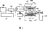
Fig. 1 illustrates the overall arrangement of the MRI equipment of using embodiments of the invention;
Fig. 2 is used to explain according to the present invention also serve as the guide wire of RF reception antenna and by the sketch map of the user mode of the conduit of guide wire guiding;
Fig. 3 is the flow chart that illustrates according to the process of the embodiment of class endoscopic images acquisition methods of the present invention;
Fig. 4 is the sketch map that the example of the 3 d image data that is obtained by class endoscopic images acquisition methods of the present invention is shown;
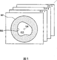
Fig. 5 is the sketch map that the example of the 3 d image data that is obtained by class endoscopic images acquisition methods of the present invention is shown;
Fig. 6 is used to explain the sketch map of handling in the central projection of class of the present invention endoscope acquisition methods;
Fig. 7 is used for explaining the sketch map of creating the method for central projection image at class endoscopic images acquisition methods of the present invention;
Fig. 8 illustrates the sketch map of being handled the class endoscopic images that obtains by central projection;
Fig. 9 is the flow chart that illustrates according to the process of another embodiment of class endoscopic images acquisition methods of the present invention; And
Figure 10 is the flow chart that illustrates according to the process of another embodiment of class endoscopic images acquisition methods of the present invention.
The specific embodiment
Embodiments of the invention are described below with reference to the accompanying drawings.
Fig. 1 shows the overall arrangement of using MRI equipment of the present invention.MRI equipment comprises that static magnetic field Magnet 102, gradient magnetic produce coil 103, RF radial coil 104, also serve as the guide wire 105 of the RF reception antenna that is used to detect the NMR signal that produces from patient 101 and the bed 112 that is used for patient is taken to measurement space, during these assemblies are installed between imaging.Static magnetic field Magnet 102 produces uniform magnetic field in measurement space, gradient magnetic produces coil 103 and provides magnetic field gradient to the static magnetic field that is produced by static magnetic field Magnet 102, and RF radial coil 104 is to the patient's radiation altofrequency magnetic field that places measurement space.
With permanent magnet, common conducting magnetic iron or superconducting electromagnet as static magnetic field Magnet 102, and with measurement space that patient 101 is placed in one in patient's 101 body axes quadratures or parallel direction on produce uniform static magnetic field.The opening static magnetic field Magnet 102 that shown example has adopted a pair of static magnetic field Magnet by the upper and lower that is arranged on measurement space to constitute, thereby go up the formation static magnetic field in last/following direction (with the orthogonal direction of patient 101 body axes), so that IV-MRI equipment can easily be operated.
Gradient magnetic produces coil 103 and is made of three coils, and described three coils produce gradient magnetic respectively on three mutually orthogonal direction of principal axis, and are connected with gradient magnetic power supply 109 respectively.RF radial coil 104 is connected with the radiating circuit 110 with agitator, manipulator and amplifier, and wherein said agitator produces the high frequency waves that have with the resonant frequency same frequency of proton.
The guide wire 105 that also serves as the RF reception antenna is connected with the receiving circuit 106 with reception amplifier, phase detectors, A/D converter etc.Guide wire 105 is formed by thinner and flexible metal wire, and realizing being inserted into the function that endoceliac conduit 200 is guided, and an end is connected with reception amplifier 106A as shown in Figure 2, with the function of realization RF reception antenna.In addition, guide wire 105 is preferably formed by the nonmagnetic metal line, thus distribution that can disturbing magnetic field.Disclosed loop free (loopless) catheter antenna can be as the guide wire 105 that also serves as the RF reception antenna in such as " Intravascular Magnetic Resonance Imaging Using aLoopless Catheter Antenna " (MRM37:112-118 (1997)).
Notice that except the guide wire 105 that also serves as the RF reception antenna, integral body or the part RF receiving coil that provides with common MRI equipment can be provided this embodiment.
Gradient magnetic power supply 109, radiating circuit 110 and receiving circuit 106 are installed in the outside between imaging, and by being installed in computer outside between imaging 111 controls equally.According to the image forming program that in computer 111, is provided with, by the operation of sequence generator 107 control gradient magnetic power supplys 109, radiating circuit 110 and receiving circuit 106.In addition, catch the NMR signal that receives by radiating circuit 110, and operate and re-construct image by carrying out such as interpolation calculating, Fourier transform scheduling algorithm.Computer 111 comprises: by the control station of its input and set handling condition etc.; Be used for the storage program, just at the memory device of processed data, treated data etc., be used to show the display unit 108 of the image that re-constructs etc.
In addition, the NMR signal that computer 111 uses radiating circuit 110 to receive is created 3 d image data, and according to the distinctive mark that comprises in the 3 d image data as will be described later, determine viewpoint and direction of visual lines, 3 d image data is handled through central projection, create the class endoscopic images, and on display unit 108, show this image.
On the other hand, conduit 200 has the hole 201 of extending in the axial direction as shown in Figure 2, so that guide wire 105 passes through.Note, though and not shown, conduit 200 has a plurality of holes of extending vertically usually, from device and the gas cell by being used for collection organization wherein.Specifically, the conduit 200 of present embodiment has two ring- shaped mark 203 and 204 that are arranged on its end 202.Labelling 203 and 204 is formed by the material that can discern from the images such as tissue the labelling on the MR image.For example, can imbed in the conduit as positive labelling with the material of high brightness response nuclear magnetic resonance, NMR (NMR) signal.On the contrary, can imbed in the conduit as negative flag with the material that produces the damaged response of signal NMR signal.Many methods are as the method for labelling 203 and 204 being imbedded in the conduit 200, and can use in these methods any.For example, can adopt the method that ferromagnetic metal powder serves as a mark of imbedding, the method of using contrast medium to serve as a mark in conduit is pulled out to conductor the outside, provides electric current and by because the damaged visible method of conductor etc. that makes of signal that the magnetic interference that electric current produces causes to conductor.In brief, be enough to form the labelling 203 and 204 of the material that can from the image of its hetero-organization on the MR image etc., discern etc.As mentioned above, according to the labelling 203 that can on the MR image, discern and 204 position and method, determine the viewpoint and the direction of visual lines that are used to create the class endoscopic images that to describe after a while.
To the detailed configuration of the MRI equipment of present embodiment be described with its operation below.Fig. 3 shows the example of continuous imaging process when inserting conduit.At first, patient 101 lies on the bed 112, is inserted in the static magnetic field and is positioned at the center of static magnetic field shown in Figure 1.Subsequently, the guide wire 105 that also serves as the RF reception antenna is inserted with groping blood vessel 210 (step S1) as the patient shown in Figure 2 101 of the main body that will diagnose or treat.The method of inserting guide wire 105 is identical with conventional lead line insertion method, and near the position the part that the guide wire insertion will be checked patient 101.At this moment, when guide wire 105 can be discerned by the NMR signal, then can carry out imaging simultaneously at this guide wire of insertion.Afterwards, insert conduit 200 (step S2) along guide wire shown in Figure 2 105.
When the end 202 of conduit 200 roughly arrives the part of wanting to observe, begin to obtain the MR image to create class endoscopic images (step S3).Formation method (image forming program) has no particular limits, as long as it can collect 3 d image data at short notice.For example, can use single EPI of bat and the EPI of bat more.In addition, can create 3 d image data, perhaps can measure 3 d image data by the three-dimensional imaging program by accumulating a plurality of two-dimentional tomogram data.
Figure 4 and 5 show by carry out the sketch map of the 3 d image data of imaging acquisition at step S3.In shown example, be chosen to picture section (for example cutting into slices 1 to 8), these are cut into slices with respect to the blood vessel 210 cardinal principle quadratures that wherein insert conduit 200, and change section simultaneously by sequentially repeating imaging, obtain a plurality of (for example 8) slice image data.Because the effective sensitivity scope of guide wire 105 is narrower, so only obtain along guide wire 105 promptly along narrower regional 220 NMR signal of blood vessel 210.For example, the part of being surrounded by the circle among Fig. 5 501 shows the range of sensitivity of guide wire 105.Usually because blood flow and can not be in blood vessel 210 reason of measuring N MR signal, what form at blood vessel wall 502 is null images, and has formed black image at the perimeter of blood vessel 210.In addition, because guide wire 105 forms by produce the damaged material of aforesaid signal in the NMR signal, therefore, form white image at guide wire 105.
Subsequently, computer 111 re-constructs class endoscopic images (step S4 and S5) by using the 3 d image data implementation center projection that obtains.In central projection was handled, at first, projection plane 602 was arranged on according to the position of predetermined direction shown in Figure 6 (direction of visual lines) away from predetermined viewpoint 601 preset distances (focal length) D, thereby made projection plane 602 and direction of visual lines quadrature or crossing.Then, carry out the pixel data be used for each section 1 to 8 and project to processing on the projection plane 602, that is, carry out the processing that is used for the pixel coordinate of section 1 to 8 is converted to the coordinate of projection plane 602.Specifically, can use in Japanese laid-open patent application No.7-120704 and 8-16813 disclosed technology to carry out processing.That is, when determined to cut into slices between 1 to 8 plane and angle between the projection plane 602 and viewpoint 601 and 1 to 8 the pixel of cutting into slices apart from the time, the pixel coordinate of section 1 to 8 can be converted to the coordinate of projection plane.Then, according to eye coordinates, direction of visual lines and focal length D, can determine the distance between the pixel of angle between slice plane and the projection plane 602 and viewpoint 601 and slice plane.
For implementation center's projection process, computer 111 uses the labelling (distinctive mark) that comprises in the 3 d image data that obtains to determine the coordinate and the direction of visual lines (step S4) of viewpoint 601.When the end of the conduit 200 that comprises labelling 203 and 204 when step S3 obtains the MR image arrives under the situation of slice plane, the section 6 of the 3 d image data that has obtained and 7 view data comprise as shown in Figure 7 labelling 203 and 204 image.Therefore, can from position, detect the terminal position of conduit 200 such as labelling 203.In addition, can come the direction of insertion of detected catheter 200 according to the straight line that makes labelling 203 be connected to labelling 204.
That is to say that two labellings 203 and 204 are arranged on the top of conduit 200 and are positioned at after the top on the position of a bit.Then, be arranged on the position of vertical labelling 203 as viewpoint.In addition, the straight line that connects two labellings 203 and 204 has the initial point 604 of the point of preset distance D as projection plane 602 as sight line vector 603 and be positioned at from the line of sight line vector 603 extensions and from the labelling 203 that serves as viewpoint.Be confirmed as projection plane 602 by initial point 604 and with sight line vector 603 plane orthogonal.
Long more focal length D will produce narrow more visual angle, can obtain thus just as by the hypermetropia camera lens to its image of observing.On the contrary, short more focal length D produces wide more visual angle, can obtain thus just as by wide-angle lens to its image of observing.Can be according to the blood vessel thickness that will observe or diagnosis target, prefocusing is provided with apart from D, perhaps in all cases, can be provided with by the control station focusing D of computer 111.
Notice that computer 111 is positive labelling or negative flag according to labelling 203 and 204, identification marking 203 and 204 differently from 3-D view.When for example labelling 203 and 204 is negative flags, and the pixel region with lowest signal value is present in the pixel that has the lowest signal value in the pixel of the blood vessel wall 502 in slice image data shown in Figure 5 (corresponding to the pixel of the guide wire 105 of present embodiment) on every side the time, determines that then labelling 203 is present in this zone.Then, the centre coordinate of labelling 203 is set to viewpoint 601.Except said method, can use method of utilizing pattern recognition etc.
When having determined viewpoint and direction of visual lines as mentioned above, in the figure of step S4 definition, carry out from viewpoint 601 to projection plane 602 central projection (step 5).Operation thus, each section pixel value of 1 to 8 are projected on the projection plane 602 in the radius pattern around the viewpoint 601.This processing begins sequentially to carry out from being positioned at viewpoint 601 sections far away, and when the next pixel value of cutting into slices and the pixel value of projection are overlapping, by the pixel value that rewrites projection from the nearer pixel value of viewpoint.Rewrite the pixel value of projection by order as mentioned above by pixel value, on projection plane 602, form the image of observing from viewpoint 601 (class endoscopic images) from the nearer section of viewpoint 601.The shading algorithm that is known as degree of depth method and volume data method for drafting can be applied to thus obtained class endoscopic images, thereby can more easily distinguish the light and the dash area of class endoscopic images.
Fig. 8 schematically shows the class endoscopic images that obtains as mentioned above.Because pictorial display is on display unit 108, so operator can be moved further conduit when observing image.When repeating step S2 is to S5 in time along with the forward motion of conduit, show new class endoscopic images with different points of view and direction of visual lines.
Because when when the top of conduit is observed it, the class endoscopic images is endovascular image, so can easily find branch's state etc. of the blood vessel relevant with conduit.Thereby, when observing vessel branch, can determine the direction that guide wire will be inserted into.In addition, because the NMR signal creation class endoscopic images that uses the guide wire 105 also serve as the RF reception antenna to receive, therefore can obtain only to insert therein the image that has high S/N ratio in the narrower part on every side such as conduit of guide wire.Thereby, insertion that can uniting conduit, observe blood vessel wall and want to observe part around.
In addition, preferably adopt the high speed imaging method, by this method, can use the NMR signal that is received by guide wire, the order of magnitude with 100 microseconds in the program of 3 d image data being carried out imaging obtains 3 d image data.According to this method, the circulation from step S2 to step S5 can be according to repeating such as circulation speed of per second, thereby can almost show the image that changes that moves with conduit in real time.When the cycle was repeated, operator observed, and can carry out for example IV-MRI biopsy effectively by the surgical technique and tools that uses conduit when needed.
Though described embodiments of the invention, the present invention never only is confined to these embodiment, but can carry out various modifications.For example, embodiment shown in Figure 3 has explained and has repeated re-constructing and the situation that re-constructs and show of class endoscopic images the imaging of 3 d image data and image in real time.Yet, each time when repeating re-constructing and when showing, unnecessaryly must obtaining 3 d image data of class endoscopic images.For example, each time when repeatedly repeating re-constructing and when showing, can obtaining two dimensional image of class endoscopic images.
In addition, can before inserting conduit 200, obtain 3 d image data, and can use 3 d image data to repeat re-constructing of class endoscopic images as illustrated in fig. 9 and show.Simultaneously, in the present embodiment, two labellings 203 can distinguishing mutually with other parts on the MR image and 204 distinctive mark are set, at end 202 places of conduit 200 as performed basic step before carrying out imaging.When beginning during imaging, conduit 200 is directed to the nonmagnetic metal guide wire 105 in the patient's 101 who wherein inserts conduit 200 the blood vessel 210, be inserted in advance (step S21) in the blood vessel.Similar to the guide wire 105 that uses in the foregoing description, guide wire 105 also serves as the RF receiving coil.Then, before inserting conduit 200, carry out the 3 d image data that the MR imaging obtains to cover the relatively large zone that comprises guide wire 5 and target location, and the 3 d image data that will re-construct is stored in the memory device of computer 111 (step S22).Subsequently, conduit 200 moves forward (step S23) along guide wire 105, when conduit during near the target location, carries out marker detection MR imaging, to detect the labelling 203 that is provided with at end 202 places of conduit 200 and 204 position (step S24).The MR image forming program can be and the similar program of carrying out at step S22 of image forming program.In this case, owing to only need the position of certification mark 203 and 204, therefore carry out in the MR of step S24 imaging, so that imaging is carried out in the zone of relative narrower.That is to say, in Fig. 4, carrying out imaging with the roughly orthogonal section of blood vessel 210.Yet, in the present embodiment,, therefore, can carry out in the MR of step S24 imaging slice plane as the part that comprises blood vessel 210 owing to from the 3 d image data that obtains in advance at step S22, can find the position of blood vessel 210.Can reduce the quantity of section thus.
In addition, as substituting of said method, can carry out formation method at the MR of step S24, thereby carry out the process of measurement of the NMR signal of the end 202 of measuring guide 200 on three direction of principal axis, the NMR signal that so measures is projected to respectively on each the direction, and according to three projection the NMR signal being carried out projection, the end 202 of detected catheter 200.By being arranged on the NMR signal that patient's 101 external common RF receiving coils receive this moment.
According to the image or the NMR signal that so obtain, can detect the position (viewpoint) and the line (direction of visual lines) (step S25) that is connected two labellings 203 and 204 of the labelling 203 on least significant end one side of two labellings 203 and 204 end 202.
Subsequently, to be defined as viewpoint in the position of the detected labelling 203 of step S25, the line that connects two labellings 203 and 204 is defined as direction of visual lines, uses the 3 d image data implementation center projection process that obtains at step S22, and re-construct class endoscopic images (step S26).That is, as shown in Figure 6,, create the image of watching from viewpoint by projection plane 602 implementation center's projection process to having predetermined focal distance D.As mentioned above, by in mobile conduit 200, repeating processing, similarly show the class endoscopic images that the image in its medium vessels changes according to the forward motion of conduit 200 with endoscope from step S23 to S26.
Embodiment according to Fig. 9, owing to carry out in the marker detection MR of step S24 imaging in the zone of relative narrower or to the section of lesser amt, can reduce imaging time, therefore, this marker detection MR imaging can be carried out in shorter time time of the MR imaging more performed than the step S3 among the 3rd embodiment.Therefore, according to this embodiment, can further improve the realtime imaging characteristic.Yet, in the present embodiment, owing to carry out MR imaging that obtains 3 d image data and the MR imaging that is used for the labelling of detected catheter in different timings, therefore, when the shape of blood vessel changes owing to the insertion conduit, perhaps when need observing the variation of shape of blood vessel, the best embodiment in the execution graph 3.
Figure 10 shows the flow chart according to another embodiment of the formation method of class endoscopic images of the present invention.Simultaneously, in the present embodiment, be provided with at end 202 places of conduit 200 can with other two labellings 203 of other parts phase region on the MR image and 204 distinctive mark, as the basic step before carrying out imaging.When imaging begins, be used for conduit 200 is directed to nonmagnetic metal guide wire 105 as the blood vessel of the patient's 101 who wherein inserts conduit 200 body cavity example, be inserted in advance in the target part (step S21).Though mainly be to insert guide wire 105 with groping, can be by insertion guide wire 105 when carrying out the MR imaging as required and monitor.Then, along guide wire 105 conduit 200 is inserted into (step S32) in the blood vessel.
Subsequently, the end 202 of conduit 200 is carried out the MR image forming program, to detect terminal 202 (step S33).The MR image forming program is the program that is called as projecting method, by this method, measures each axle in three axles, and the signal of three axles of projection.Promptly, the compartment of terrain is provided with the thickness and the position of section on the length direction of conduit 200, thereby each section is all comprised serve as can with the labelling 203 and 204 of other particular image of other parts phase region in the MR image, and the NMR signal of three normal axis measured.Wherein, the direction of three axles for example is that the flat patient 101 that wherein lies has the partly direction of the slice plane of (TRS) of horizontal component (COR), vertical longitudinal component (SAG) and vertical transverse.
When the signal measured at step S33 on three direction of principal axis, the NMR signal that produces from patient 101 receives by being arranged on patient's 101 external common RF receiving coils, and with the signal projection of each reception on each direction.Subsequently, according to projection the projection of three axles of NMR signal, detect the position of geometric markers 203 and 204.Then, as viewpoint and to use rectilinear direction that labelling 203 is connected to labelling 204 be direction of visual lines as the direction of conduit 200, determine the terminal position and the direction (step S34) of conduit 200 by usage flag 203.Note,, then can follow the tracks of it, and not need to measure the projection of three axles, thereby, can shorten Measuring Time by the converted measurement program by the projection on two direction of principal axis if the direction that moves forward of conduit 200 is not immovable.Note, can be by obtaining the two dimensional image on three direction of principal axis or the method for 3-D view, the geometric position of the end 202 of detected catheter 200.
Subsequently, carry out and the guide wire 105 MR image forming program (step S35) of orthogonal a plurality of sectioning images roughly.The NMR signal that produces from patient 101 when carrying out said procedure is received by guide wire 105, and 3 d image data is re-constructed by computer 111.Be set to viewpoint and direction of visual lines by terminal position and the direction of insertion of using 3 d image data and conduit 200 then, re-construct the central projection image, and the central projection image (step S6) that in display device, carefully re-constructs.
As mentioned above, embodiment according to Figure 10, because terminal position and direction to conduit 200 detect, and use guide wire as the RF reception antenna, terminal position and direction according to conduit 200 obtain 3 d image data, therefore, the imaging scope of 3-D view can be arranged on before the terminal position of conduit 200.In addition, owing to use projecting method that the geometric position of labelling 203 and 204 is detected, therefore, can shorten the time of position probing.The result can reduce the slice of data of 3-D view.That is, according to the embodiment of Fig. 3 and 9, owing to obtained 3 d image data before the position that detects conduit 200, therefore, slice plane must be arranged on before the assumed position of conduit and in the certain limit afterwards.Therefore, do not need to have obtained the Postductal view data of central projection, thereby increased imaging time.
As mentioned above, according to each embodiment of the present invention, when when conduit is inserted patient's blood vessel, carrying out the MRI imaging, the terminal position and the direction of detected catheter from the signal that obtains in real time, and re-construct wherein by using terminal position to be subjected to the image that central projection is handled as viewpoint.Therefore, when inserting conduit, can show just as by inserting endoscope its real time imaging of observing.The result is that the present invention inserts in the operation very effective at the conduit of IV-MRI.For example, when blood vessel during, when observing image, can determine to expect conduit is imported the branch of blood vessel wherein in position branch forward.
In addition, though conduit is provided with two labellings, and the direction of conduit (direction of visual lines) determines that by labelling it is enough at catheter tip at least one labelling being set.When conduit is provided with a labelling and repeat the MR imaging when moving forward conduit,, can detect direction of visual lines by when repeating the MR imaging, determining the change in location of labelling each time by algorithm operating.
In addition, the situation that 2-D data is accumulated as three-dimensional data has been described in the above-described embodiments.Yet the present invention never only limits to this, and by the three-dimensional measurement in step S3 or step S22 and S24 execution, can obtain three-dimensional data.
In addition, explained the situation that the aspect graph picture of blood vessel wall is shown as simply the class endoscopic images in the above-described embodiments.Yet except above-mentioned situation, the present invention has shown the inherent information of MRI effectively by showing such as fat signal according to the pattern of emphasizing.And the present invention also obtains the class endoscopic images of each body cavity except blood vessel effectively.
Claims (8)
1. MR imaging apparatus comprises:
Magnetic field generation device, other magnetic field of branch that is used to produce the static magnetic field, gradient magnetic and the high frequency magnetic field that are applied to patient; Receiving system is used to receive the NMR signal that produces from patient; Image re-constructs device, is used to use the NMR signal of reception like this, re-constructs patient's 3 d image data; Display device is used to show the image that re-constructs; And control device, be used for controlling magnetic field generator, receiving system and image and re-construct device, it is characterized in that:
The end of the conduit that is inserted into patient's body cavity be provided with can with other at least one distinctive mark of other part phase regions on the magnetic resonance image (MRI), and the metal guide line that is used for guide catheter is as receiving system; And
Image re-constructs device and uses the NMR signal that is received by guide wire to re-construct 3 d image data, uses the 3 d image data that re-constructs to detect distinctive mark, determines the terminal position and the direction of insertion of conduit according to this distinctive mark; And be set to viewpoint and direction of visual lines by terminal position and the direction of insertion of using 3 d image data and described definite conduit, re-construct the central projection image, and in display device this central projection image of demonstration.
2. equipment as claimed in claim 1, wherein image re-constructs device and is arranged on the terminal position that signal that process of measurement that the outer receiving coil of patient body receives, that on three direction of principal axis the end of conduit is carried out obtains is determined described conduit by utilization.
3. MR imaging apparatus as claimed in claim 1, wherein said control device is carried out the image forming program of a plurality of sectioning images that intersect with guide wire, to obtain NMR signal.
4. according to any the described MR imaging apparatus in the claim 1 to 3, it is characterized in that: described distinctive mark is the ring-shaped mark that coaxially is provided with at the end of conduit and conduit.
5. MR imaging apparatus according to claim 4 is characterized in that: it is characterized in that: with the position of these labellings conduit axially on by the mode of displacement at least two labellings of end setting at conduit.
6. according to any the described MR imaging apparatus in the claim 1 to 3, it is characterized in that: control device repeats following steps: first step, carry out image forming program, so that obtain 3 d image data; Second step is determined the terminal position and the direction of insertion of conduit; And third step, rearrange and the image of display centre projection.
7. MR imaging apparatus according to claim 6 is characterized in that: when repeatedly repeat first to third step each time the time, control device is all carried out once first step.
8. according to any the described MR imaging apparatus in the claim 1 to 3, it is characterized in that:, in display device, be presented at the image of sidewall surfaces of the body cavity of conduit direction of insertion front by the mode that foundation conduit on position changes.
Applications Claiming Priority (2)
| Application Number | Priority Date | Filing Date | Title |
|---|---|---|---|
| JP212157/2001 | 2001-07-12 | ||
| JP2001212157A JP3996359B2 (en) | 2001-07-12 | 2001-07-12 | Magnetic resonance imaging system |
Publications (2)
| Publication Number | Publication Date |
|---|---|
| CN1527683A CN1527683A (en) | 2004-09-08 |
| CN100350875C true CN100350875C (en) | 2007-11-28 |
Family
ID=19047361
Family Applications (1)
| Application Number | Title | Priority Date | Filing Date |
|---|---|---|---|
| CNB028140133A Expired - Fee Related CN100350875C (en) | 2001-07-12 | 2002-07-12 | Endoscopic image pickup method and magnetic resonance imaging device using the same |
Country Status (5)
| Country | Link |
|---|---|
| US (1) | US7653426B2 (en) |
| EP (1) | EP1410758A4 (en) |
| JP (1) | JP3996359B2 (en) |
| CN (1) | CN100350875C (en) |
| WO (1) | WO2003005902A1 (en) |
Families Citing this family (54)
| Publication number | Priority date | Publication date | Assignee | Title |
|---|---|---|---|---|
| US8014848B2 (en) | 2004-04-26 | 2011-09-06 | Brainlab Ag | Visualization of procedural guidelines for a medical procedure |
| DE602004013926D1 (en) * | 2004-04-26 | 2008-07-03 | Brainlab Ag | Visualization of procedural guidelines for medical procedures |
| JP4914574B2 (en) * | 2005-04-18 | 2012-04-11 | オリンパスメディカルシステムズ株式会社 | Endoscope shape detection device |
| US9289267B2 (en) * | 2005-06-14 | 2016-03-22 | Siemens Medical Solutions Usa, Inc. | Method and apparatus for minimally invasive surgery using endoscopes |
| DE102005028299A1 (en) * | 2005-06-18 | 2006-12-21 | Hensel, Renate | Walking aid on wheels, comprises forearm support elements attached above horizontal handles |
| JP5044237B2 (en) * | 2006-03-27 | 2012-10-10 | 富士フイルム株式会社 | Image recording apparatus, image recording method, and image recording program |
| JP4153963B2 (en) * | 2006-06-12 | 2008-09-24 | オリンパスメディカルシステムズ株式会社 | Endoscope insertion shape detection device |
| US20080086051A1 (en) * | 2006-09-20 | 2008-04-10 | Ethicon Endo-Surgery, Inc. | System, storage medium for a computer program, and method for displaying medical images |
| US8155728B2 (en) * | 2007-08-22 | 2012-04-10 | Ethicon Endo-Surgery, Inc. | Medical system, method, and storage medium concerning a natural orifice transluminal medical procedure |
| US20080319307A1 (en) * | 2007-06-19 | 2008-12-25 | Ethicon Endo-Surgery, Inc. | Method for medical imaging using fluorescent nanoparticles |
| US8457718B2 (en) * | 2007-03-21 | 2013-06-04 | Ethicon Endo-Surgery, Inc. | Recognizing a real world fiducial in a patient image data |
| US9629571B2 (en) | 2007-03-08 | 2017-04-25 | Sync-Rx, Ltd. | Co-use of endoluminal data and extraluminal imaging |
| JP5639764B2 (en) * | 2007-03-08 | 2014-12-10 | シンク−アールエックス,リミティド | Imaging and tools for use with moving organs |
| EP2358269B1 (en) * | 2007-03-08 | 2019-04-10 | Sync-RX, Ltd. | Image processing and tool actuation for medical procedures |
| US9968256B2 (en) | 2007-03-08 | 2018-05-15 | Sync-Rx Ltd. | Automatic identification of a tool |
| US10716528B2 (en) | 2007-03-08 | 2020-07-21 | Sync-Rx, Ltd. | Automatic display of previously-acquired endoluminal images |
| US11064964B2 (en) | 2007-03-08 | 2021-07-20 | Sync-Rx, Ltd | Determining a characteristic of a lumen by measuring velocity of a contrast agent |
| US11197651B2 (en) | 2007-03-08 | 2021-12-14 | Sync-Rx, Ltd. | Identification and presentation of device-to-vessel relative motion |
| US9375164B2 (en) | 2007-03-08 | 2016-06-28 | Sync-Rx, Ltd. | Co-use of endoluminal data and extraluminal imaging |
| US20080221434A1 (en) * | 2007-03-09 | 2008-09-11 | Voegele James W | Displaying an internal image of a body lumen of a patient |
| US20080234544A1 (en) * | 2007-03-20 | 2008-09-25 | Ethicon Endo-Sugery, Inc. | Displaying images interior and exterior to a body lumen of a patient |
| US8081810B2 (en) | 2007-03-22 | 2011-12-20 | Ethicon Endo-Surgery, Inc. | Recognizing a real world fiducial in image data of a patient |
| JP5238440B2 (en) * | 2008-10-02 | 2013-07-17 | 株式会社東芝 | Image display device and image display method |
| US11064903B2 (en) | 2008-11-18 | 2021-07-20 | Sync-Rx, Ltd | Apparatus and methods for mapping a sequence of images to a roadmap image |
| US9101286B2 (en) | 2008-11-18 | 2015-08-11 | Sync-Rx, Ltd. | Apparatus and methods for determining a dimension of a portion of a stack of endoluminal data points |
| US8855744B2 (en) | 2008-11-18 | 2014-10-07 | Sync-Rx, Ltd. | Displaying a device within an endoluminal image stack |
| US9974509B2 (en) * | 2008-11-18 | 2018-05-22 | Sync-Rx Ltd. | Image super enhancement |
| US9144394B2 (en) | 2008-11-18 | 2015-09-29 | Sync-Rx, Ltd. | Apparatus and methods for determining a plurality of local calibration factors for an image |
| US9095313B2 (en) | 2008-11-18 | 2015-08-04 | Sync-Rx, Ltd. | Accounting for non-uniform longitudinal motion during movement of an endoluminal imaging probe |
| US10362962B2 (en) | 2008-11-18 | 2019-07-30 | Synx-Rx, Ltd. | Accounting for skipped imaging locations during movement of an endoluminal imaging probe |
| JP2012529977A (en) | 2009-06-16 | 2012-11-29 | エムアールアイ・インターヴェンションズ,インコーポレイテッド | MRI guidance device and MRI guidance intervention system capable of tracking the device in near real time and generating a dynamic visualization of the device |
| JP6099640B2 (en) | 2011-06-23 | 2017-03-22 | シンク−アールエックス,リミティド | Lumen background sharpening |
| EP2549284A1 (en) * | 2011-07-21 | 2013-01-23 | Koninklijke Philips Electronics N.V. | Position marker for use in an MRI apparatus |
| CN103442643B (en) * | 2012-03-06 | 2016-03-09 | 株式会社东芝 | Image processing apparatus and X-ray imaging device |
| EP2863802B1 (en) | 2012-06-26 | 2020-11-04 | Sync-RX, Ltd. | Flow-related image processing in luminal organs |
| US10292615B2 (en) | 2012-09-20 | 2019-05-21 | The Johns Hopkins University | Methods and apparatus for accelerated, motion-corrected high-resolution MRI employing internal detectors or MRI endoscopy |
| US9282916B2 (en) * | 2013-03-01 | 2016-03-15 | Pacesetter, Inc. | Vascular branch characterization |
| CN103169445B (en) * | 2013-04-16 | 2016-07-06 | 苏州朗开医疗技术有限公司 | The air navigation aid of a kind of endoscope and system |
| US10828106B2 (en) | 2015-05-12 | 2020-11-10 | Navix International Limited | Fiducial marking for image-electromagnetic field registration |
| US10278616B2 (en) | 2015-05-12 | 2019-05-07 | Navix International Limited | Systems and methods for tracking an intrabody catheter |
| US10881455B2 (en) | 2015-05-12 | 2021-01-05 | Navix International Limited | Lesion assessment by dielectric property analysis |
| WO2016181315A1 (en) | 2015-05-12 | 2016-11-17 | Navix International Limited | Contact quality assessment by dielectric property analysis |
| WO2017055380A2 (en) * | 2015-09-30 | 2017-04-06 | Koninklijke Philips N.V. | A method for device localization using magnetic resonance imaging |
| US10524695B2 (en) | 2015-12-22 | 2020-01-07 | Biosense Webster (Israel) Ltd. | Registration between coordinate systems for visualizing a tool |
| US10244963B2 (en) | 2015-12-22 | 2019-04-02 | Biosense Webster (Israel) Ltd. | Ascertaining a position and orientation for visualizing a tool |
| EP3484362A1 (en) | 2016-07-14 | 2019-05-22 | Navix International Limited | Characteristic track catheter navigation |
| US11331029B2 (en) | 2016-11-16 | 2022-05-17 | Navix International Limited | Esophagus position detection by electrical mapping |
| US11284813B2 (en) | 2016-11-16 | 2022-03-29 | Navix International Limited | Real-time display of tissue deformation by interactions with an intra-body probe |
| US10709507B2 (en) | 2016-11-16 | 2020-07-14 | Navix International Limited | Real-time display of treatment-related tissue changes using virtual material |
| CN110177500B (en) | 2016-11-16 | 2022-03-04 | 纳维斯国际有限公司 | Dynamic visual rendering of tissue models |
| CN110198680B (en) | 2016-11-16 | 2022-09-13 | 纳维斯国际有限公司 | Ablation effectiveness estimator |
| JP6912341B2 (en) * | 2017-09-27 | 2021-08-04 | 株式会社日立製作所 | Magnetic resonance imaging device, device position detection method using it, and image-guided intervention support device |
| US10639105B2 (en) * | 2017-11-29 | 2020-05-05 | Canon Medical Systems Corporation | Navigation apparatus and method |
| EP3696593A1 (en) * | 2019-02-12 | 2020-08-19 | Leica Instruments (Singapore) Pte. Ltd. | A controller for a microscope, a corresponding method and a microscope system |
Citations (7)
| Publication number | Priority date | Publication date | Assignee | Title |
|---|---|---|---|---|
| US5271400A (en) * | 1992-04-01 | 1993-12-21 | General Electric Company | Tracking system to monitor the position and orientation of a device using magnetic resonance detection of a sample contained within the device |
| JPH07210704A (en) * | 1994-01-18 | 1995-08-11 | Hitachi Medical Corp | Method for constituting three-dimensional image |
| EP0673621A1 (en) * | 1994-03-18 | 1995-09-27 | Schneider (Europe) Ag | A medical appliance for use in magnetic resonance imaging procedures |
| JPH0816813A (en) * | 1994-06-24 | 1996-01-19 | Hitachi Medical Corp | Image-forming method/device and display method/device |
| JPH10314137A (en) * | 1997-05-20 | 1998-12-02 | Terumo Corp | Catheter |
| US6171240B1 (en) * | 1996-12-05 | 2001-01-09 | Picker International, Inc. | MRI RF catheter coil |
| JP2001070248A (en) * | 1999-09-02 | 2001-03-21 | Toshiba Corp | Image processing device |
Family Cites Families (15)
| Publication number | Priority date | Publication date | Assignee | Title |
|---|---|---|---|---|
| US5694530A (en) | 1994-01-18 | 1997-12-02 | Hitachi Medical Corporation | Method of constructing three-dimensional image according to central projection method and apparatus for same |
| JP3770280B2 (en) | 1996-03-29 | 2006-04-26 | 株式会社日立メディコ | 3D image display method and apparatus |
| US5928145A (en) | 1996-04-25 | 1999-07-27 | The Johns Hopkins University | Method of magnetic resonance imaging and spectroscopic analysis and associated apparatus employing a loopless antenna |
| US7236816B2 (en) | 1996-04-25 | 2007-06-26 | Johns Hopkins University | Biopsy and sampling needle antennas for magnetic resonance imaging-guided biopsies |
| JPH1043155A (en) * | 1996-08-01 | 1998-02-17 | Olympus Optical Co Ltd | Magnetic resonance observing device |
| US6061587A (en) * | 1997-05-15 | 2000-05-09 | Regents Of The University Of Minnesota | Method and apparatus for use with MR imaging |
| US6272370B1 (en) * | 1998-08-07 | 2001-08-07 | The Regents Of University Of Minnesota | MR-visible medical device for neurological interventions using nonlinear magnetic stereotaxis and a method imaging |
| US7048716B1 (en) * | 1997-05-15 | 2006-05-23 | Stanford University | MR-compatible devices |
| US6026316A (en) * | 1997-05-15 | 2000-02-15 | Regents Of The University Of Minnesota | Method and apparatus for use with MR imaging |
| US6675037B1 (en) * | 1999-09-29 | 2004-01-06 | Regents Of The University Of Minnesota | MRI-guided interventional mammary procedures |
| EP1267713B1 (en) * | 2000-02-01 | 2010-10-13 | SurgiVision, Inc. | Magnetic resonance imaging transseptal needle antenna |
| US6484049B1 (en) * | 2000-04-28 | 2002-11-19 | Ge Medical Systems Global Technology Company, Llc | Fluoroscopic tracking and visualization system |
| US6714809B2 (en) | 2000-11-20 | 2004-03-30 | Surgi-Vision, Inc. | Connector and guidewire connectable thereto |
| US6871086B2 (en) * | 2001-02-15 | 2005-03-22 | Robin Medical Inc. | Endoscopic examining apparatus particularly useful in MRI, a probe useful in such apparatus, and a method of making such probe |
| WO2004038442A2 (en) | 2002-10-21 | 2004-05-06 | The General Hospital Corporation D/B/A Massachusetts General Hospital | Catheter and radiofrequency coil with annular b1 filed |
-
2001
- 2001-07-12 JP JP2001212157A patent/JP3996359B2/en not_active Expired - Fee Related
-
2002
- 2002-07-12 EP EP02746007A patent/EP1410758A4/en not_active Withdrawn
- 2002-07-12 CN CNB028140133A patent/CN100350875C/en not_active Expired - Fee Related
- 2002-07-12 WO PCT/JP2002/007105 patent/WO2003005902A1/en active Application Filing
- 2002-07-12 US US10/483,444 patent/US7653426B2/en not_active Expired - Fee Related
Patent Citations (7)
| Publication number | Priority date | Publication date | Assignee | Title |
|---|---|---|---|---|
| US5271400A (en) * | 1992-04-01 | 1993-12-21 | General Electric Company | Tracking system to monitor the position and orientation of a device using magnetic resonance detection of a sample contained within the device |
| JPH07210704A (en) * | 1994-01-18 | 1995-08-11 | Hitachi Medical Corp | Method for constituting three-dimensional image |
| EP0673621A1 (en) * | 1994-03-18 | 1995-09-27 | Schneider (Europe) Ag | A medical appliance for use in magnetic resonance imaging procedures |
| JPH0816813A (en) * | 1994-06-24 | 1996-01-19 | Hitachi Medical Corp | Image-forming method/device and display method/device |
| US6171240B1 (en) * | 1996-12-05 | 2001-01-09 | Picker International, Inc. | MRI RF catheter coil |
| JPH10314137A (en) * | 1997-05-20 | 1998-12-02 | Terumo Corp | Catheter |
| JP2001070248A (en) * | 1999-09-02 | 2001-03-21 | Toshiba Corp | Image processing device |
Also Published As
| Publication number | Publication date |
|---|---|
| JP2003024298A (en) | 2003-01-28 |
| CN1527683A (en) | 2004-09-08 |
| JP3996359B2 (en) | 2007-10-24 |
| WO2003005902A1 (en) | 2003-01-23 |
| EP1410758A4 (en) | 2008-09-17 |
| US20050033164A1 (en) | 2005-02-10 |
| EP1410758A1 (en) | 2004-04-21 |
| US7653426B2 (en) | 2010-01-26 |
Similar Documents
| Publication | Publication Date | Title |
|---|---|---|
| CN100350875C (en) | Endoscopic image pickup method and magnetic resonance imaging device using the same | |
| US6975896B2 (en) | Fiducial markers for MRI | |
| CN103006335B (en) | General calibration mould for surgical navigation and calibration method | |
| CN103037761A (en) | Insertion guidance system for needles and medical components | |
| Song et al. | Development and preliminary evaluation of a motorized needle guide template for MRI-guided targeted prostate biopsy | |
| CN102413762B (en) | Interventional mr imaging with motion compensation | |
| EP1103229A2 (en) | System and method for use with imaging devices to facilitate planning of interventional procedures | |
| CN103635146A (en) | Needle length determination and calibration for insertion guidance system | |
| JP2003506118A (en) | Method for determining three-dimensional position and orientation of internal MRI receiving coil | |
| CA2505464A1 (en) | Catheter tracking with phase information | |
| JP2000139948A (en) | Method and device for planning surgical procedure | |
| US20090080750A1 (en) | Passive mr visualisation of interventional instruments | |
| US7835780B1 (en) | MR invasive device and method for active MR guidance of invasive devices with target navigation | |
| WO2002022012A1 (en) | Magnetic resonance imaging system | |
| EP2870488A2 (en) | A method for maintaining geometric alignment of scans in cases of strong patient motion | |
| CN103649766B (en) | Personalized RF coil array for the intervention of MR imaging guiding | |
| US20100102805A1 (en) | Method and arrangement for influencing and/or detecting magnetic particles in a region of action | |
| Rea et al. | System for 3-D real-time tracking of MRI-compatible devices by image processing | |
| CN101103914A (en) | Device and method for switching coordinate system between magnetic resonance system and equipment lead by the same | |
| Shang et al. | A high accuracy multi-image registration method for tracking MRI-guided robots | |
| CN106872921B (en) | MR imaging method and device | |
| CN207323541U (en) | A kind of image magnet structure for minimally invasive operation navigating system | |
| CN203122607U (en) | General calibration mold for surgical navigation | |
| Thörmer et al. | Simultaneous 3D localization of multiple MR-visible markers in fully reconstructed MR images: proof-of-concept for subsecond position tracking | |
| Seimenis et al. | An approach for preoperative planning and performance of MR-guided interventions demonstrated with a manual manipulator in a 1.5 T MRI scanner |
Legal Events
| Date | Code | Title | Description |
|---|---|---|---|
| C06 | Publication | ||
| PB01 | Publication | ||
| C10 | Entry into substantive examination | ||
| SE01 | Entry into force of request for substantive examination | ||
| C14 | Grant of patent or utility model | ||
| GR01 | Patent grant | ||
| CF01 | Termination of patent right due to non-payment of annual fee |
Granted publication date: 20071128 Termination date: 20150712 |
|
| EXPY | Termination of patent right or utility model |