CN100340203C - Electric dust collector - Google Patents
Electric dust collector Download PDFInfo
- Publication number
- CN100340203C CN100340203C CNB2005100662563A CN200510066256A CN100340203C CN 100340203 C CN100340203 C CN 100340203C CN B2005100662563 A CNB2005100662563 A CN B2005100662563A CN 200510066256 A CN200510066256 A CN 200510066256A CN 100340203 C CN100340203 C CN 100340203C
- Authority
- CN
- China
- Prior art keywords
- mentioned
- dust
- rotary body
- dedusting
- vacuum cleaner
- Prior art date
- Legal status (The legal status is an assumption and is not a legal conclusion. Google has not performed a legal analysis and makes no representation as to the accuracy of the status listed.)
- Expired - Fee Related
Links
Images


Landscapes
- Filters For Electric Vacuum Cleaners (AREA)
Abstract
The invention provides a compact vacuum cleaner having no useless space and less in ventilation loss. The vacuum cleaner includes: a waveform dust collecting filter; and a dirt removal rotary body for adding a dirt removal vibration to the rear surface of a dust collection surface in the dust collecting filter when rotation is performed. The dirt removal rotary body is arranged so that the rotation axis follows the waving direction of the dust collecting filter. The rotary body is provided with a helical spring for adding the vibration, so as to be rotated by the rotation of a cord reel.
Description
Technical field
The present invention relates to possess the electric vacuum cleaner of removing attached to the dust arrester of dust on the dust-collecting filter.
Background technology
The structure of general electric vacuum cleaner is, for example, shown in No. 3490081 communique of patent documentation 1-Japan special permission, to import electric vacuum cleaner self from the dust laden air that suction inlet sucks, catch dust by the dust collecting part in this electric vacuum cleaner self, the air that cleans is discharged to outside the dust catcher self with becoming.
Dust collecting part has by paper filter filters seizure dust, and the air that cleans becoming is discharged to the outer mode of dust catcher self; Dust is caught in filtration by dust-collecting filter, and the air of the cleaning that becomes is discharged the outer mode of dust catcher self; And the centrifugation by cyclone separating tube, separate the air and the dust that become cleaning, the air of the cleaning that will become again is discharged to outside the dust catcher self, dust then control of dust to have dust-collecting filter the cyclonic separation mode of dust collecting part.
Utilize the dust collecting part of the electric vacuum cleaner of dust-collecting filter and cyclonic separation mode, be made of one deck or which floor dust-collecting filter, the dust laden air that sucks from suction inlet is sent to electric blowing machine one side by this dust-collecting filter.At this moment, the small dust of dust-collecting filter surface attachment.
The dust-collecting filter mode in the past and the electric vacuum cleaner of cyclonic separation mode have the dust arrester of removing attached to the dust on dust-collecting filter surface between dust-collecting filter and electric blowing machine.This dust arrester is made with the face of dust-collecting filter and is installed abreast, on one side and the dedusting rotor that is installed on the dust arrester is rotated, Yi Bian make the structure of the back side vibration of dust-collecting filter.
Above-mentioned in the past the dust-collecting filter mode and the dust collection method of the electric vacuum cleaner of cyclonic separation mode, rotatablely move work by what make the dedusting rotor that is installed on the dust arrester.This moment and the general electric wires that are wound on the bobbin that use of being connected of power source pull out in use, put back to when not using.Therefore, be provided with gear in its bobbin periphery, the position relation is in right angle orientation with dust arrester.Under the position relation situation in horizontal direction of bobbin and dust arrester, need driving parts such as bevel gear.The problem that produce this moment is the expansion and the gas leakage in space, in any case need the significantly improvement of self structure and need the space.Dust arrester in the past is because be placed in the front of electric blowing machine in addition, thereby dust arrester self becomes flowing resistance, and attraction is reduced.
Summary of the invention
The present invention considers the problems referred to above, and its purpose is to provide a kind of electric vacuum cleaner, and it does not change significantly to self structure, flowing resistance is dropped to extremely low, and dust arrester with compactness of no idle space.
Electric vacuum cleaner of the present invention has: be provided in dust collecting part undulatory dust-collecting filter, be provided in the electric blowing machine at above-mentioned dust-collecting filter rear portion, vertically be configured in above-mentioned electric blowing machine side bobbin, be assembled in the driven wheel of above-mentioned bobbin inside, the travelling gear installed with above-mentioned driven wheel level, the rotation of following travelling gear apply the dedusting vibration to the back side one side of the control of dust face of above-mentioned dust-collecting filter dedusting rotary body; Above-mentioned dedusting rotary body is arranged between above-mentioned dust-collecting filter and the above-mentioned electric blowing machine, axis of rotation is along the fluctuation direction configuration of above-mentioned dust-collecting filter, and it is characterized in that: above-mentioned dedusting rotary body has along the spiral helicine dedusting vibration section of axis of rotation configuration.
Its feature also has: above-mentioned dedusting rotary body is contained in the top of above-mentioned dust-collecting filter, is disposed to top by above-mentioned electric blowing machine suction inlet middle position.
Its feature also has: the structure of above-mentioned dedusting rotary body is designed to rotate when pulling out said wires, stops the rotation when electric wire is regained above-mentioned bobbin.
By above structure, all the back side one side to above-mentioned dust-collecting filter applies vibration at every turn when using electric vacuum cleaner to pull out said wires.
Adopt the present invention, by providing self structure is not improved significantly, flowing resistance is dropped to extremely low, and the electric vacuum cleaner of dust arrester with compactness of no idle space, owing to when electric vacuum cleaner uses, dust-collecting filter is carried out dedusting at every turn, simplified control can be made, the electric power that is consumed because of the obstruction of filter mesh can be reduced.In addition, extremely low owing to the flowing resistance of electric blowing machine being dropped to, thereby have the effect that the suction force of preventing reduces.
Description of drawings
Fig. 1 is the stereoscopic figure of the electric vacuum cleaner self of embodiments of the invention.
Fig. 2 is opening loam cake, pulling down the stereoscopic figure of electric vacuum cleaner self of the state of collecting unit of dust of expression embodiments of the invention.
Fig. 3 is opening loam cake, installing the stereoscopic figure of electric vacuum cleaner self of the state of collecting unit of dust of expression embodiments of the invention.
Fig. 4 be the embodiment of the invention from the observed front view of collecting unit of dust rear side.
Fig. 5 is the sectional view along the A-A line of Fig. 4 of the embodiment of the invention.
Fig. 6 is the observed stereoscopic figure in the front side from collecting unit of dust of the embodiment of the invention.
Fig. 7 be the embodiment of the invention from the observed stereoscopic figure of collecting unit of dust rear side.
Fig. 8 is the sectional view along the B-B line of Fig. 5 of the embodiment of the invention.
Fig. 9 is the vertical view of pulling down the electric vacuum cleaner self that the upside main body cover observes from the top of the embodiment of the invention.
Figure 10 is the longitudinal section of the electric vacuum cleaner self of the embodiment of the invention.
Figure 11 is the travelling gear of dust arrester unit of the expression embodiment of the invention and the intermeshing stereogram of driven wheel of spool.
Figure 12 is the intermeshing vertical view of the driven wheel of the travelling gear of dust arrester unit of the expression embodiment of the invention and spool.
Figure 13 is the dust-collecting filter of the expression embodiment of the invention and the helical spring graph of a relation of dedusting rotary body.
Figure 14 is the dedusting rotary body assembling sequence figure of the expression embodiment of the invention.
Figure 15 is the front view of the dust arrester supporting frame of the embodiment of the invention.
Figure 16 is the schematic diagram after on the dust arrester supporting frame dedusting rotary body being installed of the expression embodiment of the invention.
Figure 17 is the schematic diagram behind installation shaft envelope parts on the dedusting rotary body of the expression embodiment of the invention.
Figure 18 is the schematic diagram after on the dedusting rotary body travelling gear being installed of the expression embodiment of the invention.
Figure 19 is the dedusting rotary body of the expression embodiment of the invention and the enlarged drawing of axle envelope parts.
Figure 20 is the sectional view along the C-C line of Figure 18 of the embodiment of the invention.
Figure 21 is the D portion enlarged drawing of Figure 20 of the embodiment of the invention.
Figure 22 is the travelling gear of Rotary dust collecting device unit of the expression embodiment of the invention and the intermeshing front view of driven wheel of spool.
Figure 23 is the travelling gear of dedusting rotary body of the expression embodiment of the invention and the intermeshing vertical view of driven wheel of spool.
Figure 24 is that the E of Figure 22 of the embodiment of the invention is to view.
Figure 25 is the stereoscopic figure of the dedusting rotary body of the embodiment of the invention.
Figure 26 is the stereoscopic figure of tubular shape parts of the dedusting rotary body of the embodiment of the invention.
Figure 27 is the front view of the cartridge of the embodiment of the invention.
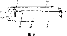
Figure 28 is the helical spring front view of the embodiment of the invention.
Figure 29 is the stereogram of the end ring of the embodiment of the invention.
Figure 30 is the sectional view along the F-F line of Figure 27 of the embodiment of the invention.
Figure 31 is the sectional view along the G-G line of Figure 27 of the embodiment of the invention.
Figure 32 is the sectional view along the H-H line of Figure 14 (6) of the embodiment of the invention.
Figure 33 is the schematic diagram before the dedusting of the expression embodiment of the invention begins.
Figure 34 is the schematic diagram at the dedusting initial stage of the expression embodiment of the invention.
Figure 35 is the ongoing schematic diagram of dedusting of the expression embodiment of the invention.
Figure 36 is the stereogram of the cartridge of another embodiment of the present invention.
The specific embodiment
Below, with reference to accompanying drawing, embodiments of the invention are described.
At first, press the summary of the order explanation electric vacuum cleaner of Fig. 1-Figure 10.
As shown in Figure 1-Figure 3, the electric vacuum cleaner main body cover has upside main body cover 1 and downside main body cover 2.Main body cover has the wheel 3 and the Caster (not shown) of walking usefulness.But be contained on the upside main body cover 1 loam cake 4 free switch.Collecting unit of dust 5 after opening loam cake 4, the folding and unfolding portion 6 of the collecting unit of dust of the main body cover of can packing into, or therefrom take out.
As Fig. 4-shown in Figure 8, collecting unit of dust 5 has dust-collecting box 7 and undulatory dust-collecting filter 8.Has the cyclone type dust collecting part in the inside of dust-collecting box 7.The cyclone type dust collecting part has cyclone type separation chamber 20 and dust storage chamber 21.
There is rubbish suction inlet 22 front side of dust-collecting box 7.Be separated into heavy rubbish and light rubbish by this rubbish suction inlet 22 with the dust that air-flow flows in the separation chamber 20, control of dust is in dust storage chamber 21.Because the upstream side at dust-collecting filter 8 has filter 23, thereby most of dust is trapped in dust storage chamber 21.Not being filtered the undulatory dust-collecting filter 8 that thin dirt that device 23 catches is provided in the downstream of filter 23 catches.
Dust-collecting filter 8 usefulness nonwoven etc. are made corrugated.Because the periphery molding synthetic resin of dust-collecting filter 8, thereby can keep its corrugated.Because corrugated dust-collecting filter 8 has pliability, thereby by the back side one side (dust is caught the back side one side of face) is applied vibration, the dust of being caught is shaken to fall.
As Fig. 9, shown in Figure 10, electric blowing machine 24 places the rear side in the main body cover.Bobbin 25 places the rear side in the main body cover, makes it laterally adjacent with electric blowing machine 24.Collecting unit of dust 5 places the front side in the main body cover.The installation of dust arrester unit 26 makes it between dust-collecting filter 8 and electric blowing machine 24.
Bobbin 25 has spool 41, and it is reeled to the conductor wire 40 of electric blowing machine 24 power supplies; The direction of the axis of rotation of this spool 41 places and makes it towards electric blowing machine 24 and be level.Spool 41 has the driven wheel 42 that is used as the spur gear that drives the driving section in periphery.
As Figure 11, Figure 12, Figure 13 and even Figure 15-shown in Figure 24, dust arrester unit 26 has dust arrester supporting frame 43 and dedusting rotary body 44.
Dust arrester supporting frame 43 is made by synthetic resin.Dust arrester supporting frame 43 has air vent 45.Dedusting rotary body 44 is located at the top position of air vent 45.Air vent 45 occupied dust arrester supporting frame 43 very on a large scale, be arranged to be located at the relative part of suction inlet of dust-collecting filter 8 and electric blowing machine 24 at least.Sucked by rubbish suction inlet 22, the air that has passed through the inside of dust-collecting box 7 and dust-collecting filter 8 air vent 45 of flowing through is inhaled into the suction inlet of electric blowing machine 24.
Dedusting rotary body 44, can utilize electric blowing machine 24 to carry out brute force and suck so do not constitute the circulation obstacle by the air stream of air vent 45 owing to avoid the top position that air vent 45 is arranged on air vent 45.
In addition, dedusting rotary body 44 is owing to making the supporting structure of its two ends with the rotating bearing component free rotary ground supporting, therefore, dedusting rotary body 44 and rotating bearing component do not have ground, front and back and come between dust-collecting filter 8 and the electric blowing machine 24, like this, can dwindle the space, make its compactness.
Also have, air vent 45 has many grid and rib; Because air vent 45 is by these grid and rib, divide carefullyyer, when because of carelessness collecting unit of dust 5 not being installed and sucking dust, bigger dust can be caught on grid and the rib before electric blowing machine 24, can prevent electric blowing machine 24 breakages.
With reference to Figure 14, Figure 25-Figure 30 is elaborated to the dedusting rotary body.
Dedusting rotary body 44 has cartridge 46 cylindraceous, as the helical spring 47 and the end ring 48 of dedusting vibration section.
As Figure 27, shown in Figure 28, cartridge cylindraceous 46 is made by synthetic resin, has inner space 49 cartridges 46 that connect vertically to have many (4) extending vertically to keep rib 60 in periphery; Keep the 60 equidistant interior weeks that are configured to keep helical spring 47 of rib.
The periphery of cartridge 46 at two ends has several (2) circular-arc engaging protrusion 61. and by utilizing these circular-arc engaging protrusion 61 end ring 48 is installed on the cartridge 46, and then fixedly helical spring can not come off it.
As shown in figure 29, end ring 48 has the auxiliary section 62 that cooperates with circular-arc engaging protrusion 61 in the side within it.Auxiliary section 62 is made of the mating groove 64 that is provided with at mating flanges 63 places.Mating groove 64 has stopper section 65 in an opposite side (inboard) of inlet.End ring 48 rotates by rotating to circular-arc engaging protrusion 61 and contacts with stopper section 65 then to give reliably and fix.The interval of two mating flanges 63 is slightly larger than the arc length of circular-arc engaging protrusion 61.By circular-arc engaging protrusion 61 is embedded in this big slightly interval, the end ring 48 of screwing on just can insert circular-arc engaging protrusion 61 and be fastened in the mating groove 64.
As shown in figure 28, have with identical external diameter spiral-shaped along axis direction as the helical spring 47 of dedusting vibration section.The about 26mm of the external diameter of helical spring 47.As wire rod, it has used the piano wire rod of line footpath as 1mm.Helical spring 47 has been implemented antirust electroplating processes.Also can adopt the wire rod of stainless steel wire or synthetic resin.
Shown in figure 32, helical spring 47 directly remains on the periphery of cartridge 46 within it with the clearance G of about 1mm between the periphery of side and maintenance rib 60.The gap of cartridge 46 and helical spring 47 is keeping rib 60 place in addition to become bigger.
In addition, helical spring 47 has two rotation prevention portions 67 at two ends.The rotation prevention portion 67 that is arranged on retainer ring 66 two ends is by the formation that curves inwardly, thereby makes the length direction of the two ends of retainer ring 66 along cartridge 46.A rotation prevention portion 67 becomes terminal, and another rotation prevention portion 6 links to each other with helical spring 47.As shown in figure 25, two rotation prevention portions 67 are arranged to be engaged between the end of circular-arc engaging protrusion 61 of adjacency.Helical spring 47 utilizes two rotation prevention portion 67 splines, remains on the cartridge 46.Be held and the helical spring 47 of spline,, be fixed on reliably on the cartridge 46 and can not break away from by the installation of end ring 48.Therefore, carry out dedusting when rotation,, thereby make dedusting everything goes well with your work and carry out because helical spring can not come off with cartridge 46 yet at dedusting rotary body 44.
Dedusting rotary body 44 has slave end rotary body bolster 80 and driving side bolster 81.Below with reference to Figure 14, Figure 30-Figure 32, the assembling of the dedusting rotary body that comprises this slave end rotary body bolster 80 and driving side bolster 81 is described.
The cartridge 46 of dedusting rotary body 44 with slave end rotary body bolster 80 and 81 folding and unfoldings of driving side bolster in inner space 49.As (1) of Figure 14, shown in Figure 30, the left half side part of inner space 49 has 4 smooth standstill faces 82; As Figure 14 (1), shown in Figure 31, remaining right half side part forms the circular space of non-spline.Left end at cartridge 46 is provided with the anticreep bead 83 of diameter less than the internal diameter of inner space 49.
Figure 14 (1) is the single part of cartridge 46.Figure 14 (2) expression cartridge 46 has been installed the state of helical spring 47.Figure 14 (3) expression is with pack into the state of inner space 49 of cartridge 46 of slave end rotary body bolster 80.Slave end rotary body bolster 80 inserts from the right side of cartridge 46, keeps it not come off by the anticreep bead.
Slave end rotary body bolster 80 has standard shaft 84, median plate 85, and end plate 86, splinter bar 87, the slave end aixs cylinder plays 88.The periphery of median plate 85 and end plate 86 is owing to make the identical shape in inner space with 82 places, standstill face, thereby makes 80 pairs of cartridge 46 splines of slave end rotary body bolster.The slave end aixs cylinder plays 88 states that are in the left end that protrudes in cartridge 46.
Figure 14 (4) expression is installed in energizing spring 89 state on the splinter bar 87 of slave end rotary body bolster 80.As Figure 14 (5) shown in, intermediate 100 embedded and be installed in splinter bar 87 on thereafter.Though it is intermediate 100 is entrenched on the splinter bar with being free to slide along its length, restrained and can not rotate in direction of rotation.Shown in figure 32, because the cross section of splinter bar is the H shape, the hole on the embedding splinter bar of intermediate 100 also is the H shape, thereby can not rotate.
Figure 14 (6) is illustrated in the state that driving side bolster 81 has been installed on the cartridge 46.Driving side bolster 81 can rotate freely, and can be installed in the inner space 49 of cartridge 46 with being free to slide vertically.The outer end of driving side bolster 81 has drive-side shaft projection 101.
Driving side bolster 81 has embedded hole in an opposite side of drive-side shaft projection 101, can rotate freely in this embedded hole, and vertically intermediate 100 can be installed with being free to slide.Be provided with driving pawl in the embedded hole inboard that is positioned at drive-side shaft projection 101 opposite sides.Intermediate 100 has driven ratchet at the end face of the inboard that embeds embedded hole.The engagement of driving pawl and driven ratchet applies power by energizing spring 89.
The rotation of driving side bolster 81 passes to slave end rotary body bolster 80 by driving pawl and driven ratchet.The transmission of rotation is only carried out in the rotation of a direction of driving side bolster 81, and the rotation of not transmitting another direction.The rotation of a direction is meshing with each other by driving pawl and driven ratchet and is rotated transmission.For counter-rotating, because driving pawl and driven ratchet do not mesh, the intermediate 100 of driven ratchet moves energizing spring 89 compressions, and the rotation transmission can't be carried out.
So, the dedusting rotary body of assembling is installed on the dust arrester supporting frame.Installation to the dedusting rotary body describes below.
Figure 15 represents to install the dust arrester supporting frame 43 before the dedusting rotary body 44.
Dust arrester supporting frame 43 has the dust removing body that dedusting rotary body 44 is installed in the top of air vent 45 portion 102 is set.But the dust removing body with folding and unfolding dust arrester supporting frame 43 sizes be provided with portion 102 by wall divide forms about, about reach the back, make the structure that does not have aeration.In being provided with the left side wall of portion 102, dust removing body is provided with the bearing block 104 of slave end dead eye 103.The sidewall 105 that dust removing body is provided with the right side of portion 102 has inboard bearing hole 106.This inboard bearing hole 106 is to lead to outside hole; Dust removing body is provided with portion 102 and has the dedusting rotary body rear support portion 107 of extending about two overleaf.
Figure 16 is illustrated in dedusting rotary body 44 places the state that dust removing body is provided with portion 102 has been installed.
Slave end rotary body bolster 80 and driving side bolster 81 are pushed cartridge 46 inboards.Since the slave end aixs cylinder rise 88 and drive-side shaft projection 101 enter in cartridge 46 two ends, thereby the 44 easy folding and unfoldings of dedusting rotary body are provided with in the portion 102 at dust removing body.And, aim at slave end dead eye 103 by making the slave end aixs cylinder play 88, and, expose and be embedded in the slave end dead eye 103 thereby make the slave end aixs cylinder play 88 by energizing spring 89 pushings.Equally, by drive-side shaft projection 101 is aimed at inboard bearing hole 106, drive-side shaft projection 101 also by energizing spring 89 pushings, is fitted in the inboard bearing hole 106.(as shown in figure 17)
As Figure 17, shown in Figure 19, the setting of drive-side shaft projection 101 makes it protrude in side wall portion 105 outside sides.Axle envelope parts 108 are installed at drive-side shaft projection 101 places.Axle envelope parts 108 have the function of inhibition air through the clearance leakage of inboard bearing hole 106 and drive-side shaft projection 101.
Axle sealing 108 is made by rubber or soft plastic material, roughly is to have a portion 120, the shape of the L word of flange 121.Axle envelope parts 108 have the sealing projection 122 of ring-type week in tube portion 120.In addition at the locator protrusions that has ring-type week 123 of the tube portion 120 of the root that is positioned at flange 121.The cross sectional shape semicircular in shape of sealing projection 122.The flange 121 of axle envelope parts 108 is arranged to side wall portion 105 outside sliding-contacts and is kept sealing function.
Drive-side shaft projection 101 has annular seal groove and ring-type locating slot position in periphery.Seal groove is arranged on the front end near drive-side shaft projection 101, and locating slot is arranged near drive-side shaft projection 101 roots.The axle envelope parts 108 that are installed in drive-side shaft projection 101 places make sealing projection 122 chimeric with seal groove, make locator protrusions 123 and locating slot chimeric.With the chimeric locator protrusions 123 of locating slot except positioning function is arranged, also have the sealing function same with sealing projection 122.
The travelling gear 124 of rotary transmission part as shown in figure 18, is installed in the end of drive-side shaft projection 101.Travelling gear 124 usefulness screws are fixed.
As Figure 20, shown in Figure 21, be installed in dedusting be provided with in the portion 102 dedusting rotary body 44 with dorsad the state of dedusting rotary body rear support portion 107 install.Two dedusting rotary body rear support portions 107 are arranged to extend along the length direction of dedusting rotary body 44.The interval G (2-3mm) of the periphery of helical spring 47 and dedusting rotary body rear support portion 107 is arranged to same widths along its length.
The dismounting of dedusting rotary body 44 is by inserting with the patchhole 125 from the bottom of the bearing block 104 that is arranged on Figure 15-shown in Figure 180 such as screwdriver, slave end rotary body bolster 80 is shifted onto the inboard of cartridge 46, like this, break away from slave end dead eye 103 because the slave end aixs cylinder plays 88, thereby be easy to carry out.To leak in order preventing to suck, usually patchhole 125 to be added upper cover.In addition, if the dismounting of dedusting rotary body 44 also can be without patchhole 125 when adopting other method.
With as mentioned above the assembling after dust arrester unit 26 as Fig. 9, Figure 10, Figure 12, shown in Figure 22, be arranged between electric blowing machine 24 and the collecting unit of dust 5.
Why can realize the engagement of this assembling function admirable, be because adopted the axis of rotation that engagement is configured in travelling gear 124 to be positioned at the structure of the axis of rotation top position of driven wheel 42.
In addition, because with the axis of rotation configured in parallel of axis of rotation and the driven wheel 42 of travelling gear 124, and two gears are all made spur gear, thereby two outer peripheral gears butt joints are meshed.Even how spool 41 vibrates in the axis of rotation direction, two gear meshing can both be kept stable engagement, can carry out the dedusting rotation of dedusting rotary body 44 reliably.
To the rotating actuator of dedusting rotary body 44 owing to have only the driven wheel 42 of spool 41 and 124 two parts of travelling gear of dedusting rotary body 44, thereby have have when can realize compact structure simple in structure, assembling is rotated the inferior advantage of transmission loss easily.
Also have, rotating actuator can utilize bevel gear, various gears such as helical gear.
Dedusting to dust-collecting filter describes below.
As shown in figure 13, the periphery of helical spring 47 is arranged to enter between the ripple of dust-collecting filter 8.Enter the degree of depth and be about 1mm.Along with the rotation of helical spring 47, the crest of undulatory dust-collecting filter 8 is vibrated to carry out dedusting.
Because the transverse width of dust-collecting filter 8 is about 100mm, the length desire of helical spring 47 is 80mm, thereby the whole transverse width of almost crossing over dust-collecting filter 8 carries out dedusting.
Dust-collecting filter 8 is owing to be arranged to vertically advance between ripple, and dedusting rotary body 44 is arranged on the top position of dust-collecting filter 8, thereby accumulates in the below of dust-collecting filter 8 by the shaken dust that falls of dust-collecting filter.
The dedusting of dust-collecting filter 8 is undertaken by the rotation of dedusting rotary body 44.The rotation of dedusting rotary body 44 is only carried out when pulling out the electric wire 40 of bobbin 25.When electric wire 40 rollbacks,, then be just to increase because bear the load of the disc spring of rollback electric wire 40 if dedusting rotary body 44 is turned round.So, if increase disc spring intensity, even when the rollback electric wire, also can carry out dedusting.
In addition, by the electric wire 40 of pulling out bobbin 25, the rotation of spool 41 is delivered to travelling gear 124 through rotating actuator shown in Figure 23 (driven wheel 42 of spool 41 and the travelling gear 124 of dedusting rotary body 44).Driving side bolster 81 is passed through in the rotation of travelling gear 124, intermediate 100, and slave end rotary body bolster 80 is delivered to cartridge 46.Like this, make 44 rotations of dedusting rotary body.
In the rollback of electric wire 40, because spool 41 is counter-rotating, thereby rotation is transmitted and is interrupted between the driven ratchet of the driving pawl of driving side bolster 81 and intermediate 100, and then rotation can not be delivered to dedusting rotary body 44.
Figure 33-Figure 35 represents to use the dedusting pattern of the dust-collecting filter 8 of helical spring 47.
Figure 33 is the preceding state of helical spring 47 rotations of expression dedusting rotary body 44.As shown in figure 34, be accompanied by the rotation of helical spring 47, the crest of dust-collecting filter 8 is pushed left.When the crest of dust-collecting filter 8 was crooked left, strain also took place left in helical spring 47, and helical spring 47 constantly moves on the top of crest, and is crooked more as shown in figure 35, and distortion is increased.And in case cross crest, helical spring 47 is by ejecting from laterally that a left side is adjacent crest, thereby makes dust-collecting filter 8 vibrations, will shake attached to the dust on the surface (dust is caught face) of dust-collecting filter 8.In addition, in case cross crest,, dust and filter plane are peeled off because original position is arrived in the deformation-recovery that is accumulated on the dust-collecting filter 8, thereby vibrates dust-collecting filter 8 intensely.The dedusting of this dust-collecting filter 8 is carried out in wider scope along the scope of the length direction of dedusting rotary body 44, by electric wire 40 is pulled out once, because more than helical spring 47 rotations 10 circles, thereby can carry out dedusting repeatedly, obtain higher dust removal performance.
In addition, from the crest dedusting of real oscillation crosswise dust-collecting filter 8, owing to have no equally to carry out along the length direction scope of dedusting rotary body 44, thereby be not easy to produce except that dust spot with departing from.Also have, utilize the dedusting of helical spring 47 rotations and since dust-collecting filter 8 all touch helical spring 47 everywhere, thereby can not make load produce big change, the operation of pulling out of the electric wire 40 that is easy to advance because of the difference of position of rotation.
Have again, owing at the internal diameter of helical spring 47 with keep being provided with between the periphery of rib 60 clearance G about 1mm,, can carry out good dedusting so the periphery of helical spring 47 is entered between the ripple of dust-collecting filter 8 reliably.
And, owing to will be arranged on an opposite side of dust-collecting filter 8 along two dedusting rotary body rear support portions 107 that dedusting rotary body 44 length directions extend, so when the dedusting rotation of dedusting rotary body 44, even helical spring 47 is pushed to rear side because of the reaction force (reaction force that produces when following deflection) of the crest of dust-collecting filter 8, also can be blocked by dedusting rotary body rear support portion 107.Thus,, helical spring 47 fully is out of shape, can effectively vibrates the crest of dust-collecting filter 8 because helical spring 47 can not retreat to rear side.
Also have, as described above, though the ripple of making two dust-collecting filters 8 inserts between the pitch of helical spring 47, also can make the mode that several ripples are inserted.
Can also use screw rod, worm screw replaces helical spring 47.
Figure 36 represents other embodiment of cartridge.
Because retainer ring 66 is fixed between circular-arc engaging protrusion 132 and the end retainer ring 133, thereby can suppress coming off of helical spring 47.Because two rotation prevention portions 67 are clipped between the end of circular-arc engaging protrusion 132, thereby can carry out the spline of helical spring 47.This cartridge 130 does not need the fixedly end ring 48 of helical spring 47.
Claims (19)
1. electric vacuum cleaner, it has undulatory dust-collecting filter and is accompanied by rotation applies the dedusting vibration to the back side one side of the control of dust face of above-mentioned dust-collecting filter dedusting rotary body, above-mentioned dedusting rotary body, the direction configuration axis of rotation along the ripple of above-mentioned dust-collecting filter is characterized in that:
Above-mentioned dedusting rotary body has along the spiral helicine dedusting vibration section of above-mentioned axis of rotation configuration.
2. electric vacuum cleaner according to claim 1 is characterized in that: above-mentioned dedusting vibration section comprises helical spring, screw rod, one of worm screw.
3. electric vacuum cleaner according to claim 1 is characterized in that: the outer circumferential side of above-mentioned dedusting vibration section is provided with in the mode between the ripple that inserts above-mentioned dust-collecting filter.
4. electric vacuum cleaner according to claim 1, it is characterized in that: one side possesses electric blowing machine at the above-mentioned dust-collecting filter back side, the suction inlet of this electric blowing machine is arranged to relative with the back side one side central authorities of above-mentioned dust-collecting filter, above-mentioned dedusting rotary body is near the back side upside setting of above-mentioned dust-collecting filter.
5. electric vacuum cleaner according to claim 1 is characterized in that: above-mentioned dedusting rotary body also has cartridge cylindraceous, and above-mentioned spiral helicine dedusting vibration section is the helical spring that is enclosed within its periphery along the axis direction of above-mentioned cartridge.
6. electric vacuum cleaner according to claim 5 is characterized in that: the two ends of above-mentioned dedusting vibration section stop rotation in the end of above-mentioned cartridge, and are come off by the end ring prevention of the end that is located at cartridge.
7. electric vacuum cleaner according to claim 5 is characterized in that: fixedly several of the interior week of the dedusting vibration section periphery that keeps ribs to be arranged in above-mentioned cartridge is extended along its length.
8. electric vacuum cleaner according to claim 1 is characterized in that: one side possesses electric blowing machine at the back side of above-mentioned dust-collecting filter, and it is relative with the above-mentioned dust-collecting filter back side one side central authorities that the suction inlet of this electric blowing machine is arranged to;
The dust arrester supporting frame is clipped between above-mentioned dust-collecting filter and the electric blowing machine;
Above-mentioned dust arrester supporting frame has air vent in the relative part of suction inlet of above-mentioned dust-collecting filter and above-mentioned electric blowing machine at least, and is provided with the dust removing body that is provided with above-mentioned dedusting rotary body in the top position of air vent portion is set.
9. electric vacuum cleaner according to claim 8 is characterized in that: above-mentioned dedusting rotary body rotation also can be bearing in above-mentioned dust removing body freely with freely installing and removing and be provided with in the portion.
10. electric vacuum cleaner according to claim 9 is characterized in that: slave end rotary body bolster and driving side bolster are embedded in the inner space of above-mentioned cartridge vertically with being free to slide;
Above-mentioned slave end rotary body bolster rises being provided with the slave end aixs cylinder with end that above-mentioned driving side bolster opposite position becomes an opposite side;
Above-mentioned driving side bolster is being provided with the drive-side shaft projection with end that above-mentioned slave end rotary body bolster opposite position becomes an opposite side;
But the slave end dead eye that one end setting free rotary ground supporting slave end aixs cylinder of portion rises is set at above-mentioned dust removing body; But the inboard bearing hole of the other end setting free rotary ground supporting drive-side shaft projection of portion is set at above-mentioned dust removing body;
In the inner space of above-mentioned cartridge, be arranged on make above-mentioned slave end rotary body bolster and above-mentioned driving side bolster mutually away from direction on afterburning energizing spring; Utilize above-mentioned energizing spring to keep making above-mentioned slave end aixs cylinder to rise and embed in the above-mentioned slave end dead eye, and make above-mentioned drive-side shaft projection embed state in the above-mentioned inboard bearing hole.
11. electric vacuum cleaner according to claim 10 is characterized in that: axle is sealed the periphery that parts embed above-mentioned drive-side shaft projection, and make the side of axle envelope parts and the lateral surface sliding-contact of the side wall portion that constitutes above-mentioned inboard bearing hole.
12. electric vacuum cleaner according to claim 10 is characterized in that: above-mentioned slave end rotary body bolster has the splinter bar that extends to the opposite side that above-mentioned slave end aixs cylinder rises, and above-mentioned energizing spring is installed on splinter bar;
Above-mentioned slave end rotary body bolster combines in direction of rotation with above-mentioned cartridge;
Above-mentioned driving side bolster has driving pawl in an opposite side of above-mentioned drive-side shaft projection;
Be bearing in the length direction of above-mentioned splinter bar and the intermediate that combines with splinter bar in direction of rotation sliding freely, have and the intermeshing driven ratchet of above-mentioned driving pawl in the opposite side of pushing end face of the above-mentioned energizing spring of pushing;
End in above-mentioned drive-side shaft projection is provided with the rotary transmission part that comprises travelling gear.
13. electric vacuum cleaner according to claim 8, it is characterized in that: the above-mentioned dust removing body portion of setting has near the periphery of the dedusting vibration section of above-mentioned dedusting rotary body and the dedusting rotary body rear support portion of extending in the axis of rotation direction of dedusting rotary body, this dedusting rotary body rear support portion and dedusting rotary body form the gap, are positioned at an opposite side of above-mentioned dust-collecting filter.
14. electric vacuum cleaner according to claim 11 is characterized in that: it is roughly L-shaped that axle envelope parts have the cross section of a portion and flange; Above-mentioned tube portion is embedded in the periphery of above-mentioned drive-side shaft projection; The lateral surface sliding-contact of above-mentioned flange and above-mentioned sidewall paneling.
15. electric vacuum cleaner according to claim 14 is characterized in that: in the periphery of above-mentioned drive-side shaft projection, the locating slot of ring-type is set at the root place near the drive-side shaft projection, at the annular seal groove that the cross section semicircular in shape is set near the place, end;
In the interior week that above-mentioned axle seals the tube portion of parts, the annular seal projection of the cross section semicircular in shape that setting and above-mentioned seal groove are chimeric; Week in the above-mentioned tube portion that is positioned at above-mentioned flange root is provided with the locator protrusions that cooperates with above-mentioned locating slot.
16. electric vacuum cleaner according to claim 12 is characterized in that: above-mentioned electric blowing machine has the spool of the electric wire be used to power of reeling;
The travelling gear of above-mentioned rotary transmission part and the gears engaged that is arranged on the spool of said wires axle.
17. electric vacuum cleaner according to claim 16 is characterized in that: when being wound on electric wire on the said reel, then disconnect the rotation transmission that is sent to above-mentioned driven ratchet by above-mentioned driving pawl; When pulling out electric wire, above-mentioned driving pawl and above-mentioned driven ratchet are meshing with each other to realize transmission.
18. electric vacuum cleaner according to claim 7 is characterized in that: the periphery at the two ends of above-mentioned cartridge is provided with several circular-arc engaging protrusion; Be provided with the retainer ring of periphery that is fixed on the cartridge of above-mentioned dedusting rotary body with elastic force at the helical spring two ends that form above-mentioned dedusting vibration section;
At the two ends of said fixing ring, be provided with along the aduncate rotation prevention portion of the length direction of above-mentioned cartridge, and make between the end of these two rotation prevention portions and the above-mentioned circular-arc engaging protrusion of adjacency and cooperate.
19. electric vacuum cleaner according to claim 6 is characterized in that: the periphery at the two ends of above-mentioned cartridge is provided with several circular-arc engaging protrusion; At above-mentioned end ring position, be provided with the auxiliary section that cooperates with above-mentioned circular-arc engaging protrusion.
Applications Claiming Priority (2)
| Application Number | Priority Date | Filing Date | Title |
|---|---|---|---|
| JP2004129736A JP4252927B2 (en) | 2004-04-26 | 2004-04-26 | Electric vacuum cleaner |
| JP2004129736 | 2004-04-26 |
Publications (2)
| Publication Number | Publication Date |
|---|---|
| CN1689501A CN1689501A (en) | 2005-11-02 |
| CN100340203C true CN100340203C (en) | 2007-10-03 |
Family
ID=35345483
Family Applications (1)
| Application Number | Title | Priority Date | Filing Date |
|---|---|---|---|
| CNB2005100662563A Expired - Fee Related CN100340203C (en) | 2004-04-26 | 2005-04-25 | Electric dust collector |
Country Status (2)
| Country | Link |
|---|---|
| JP (1) | JP4252927B2 (en) |
| CN (1) | CN100340203C (en) |
Families Citing this family (6)
| Publication number | Priority date | Publication date | Assignee | Title |
|---|---|---|---|---|
| US7640625B2 (en) * | 2007-04-30 | 2010-01-05 | Samsung Gwangju Electronics Co., Ltd. | Vacuum cleaner |
| JP5310320B2 (en) * | 2009-07-03 | 2013-10-09 | 三菱電機株式会社 | Electric vacuum cleaner |
| CN109288450B (en) * | 2018-09-11 | 2021-03-26 | 安克创新科技股份有限公司 | Intelligent self-moving equipment and dust box assembly thereof |
| CN111203055A (en) * | 2018-11-22 | 2020-05-29 | 余姚市雷阵雨电器有限公司 | Suction hose body shake removing mechanism |
| JP7240206B2 (en) | 2019-03-05 | 2023-03-15 | 株式会社マキタ | backpack type dust collector |
| CN110064253B (en) * | 2019-04-19 | 2021-05-14 | 绍兴市晟途环保科技有限公司 | Cleaning, vibrating and ash removing device for dust remover |
Citations (4)
| Publication number | Priority date | Publication date | Assignee | Title |
|---|---|---|---|---|
| JPS5717630B2 (en) * | 1978-06-23 | 1982-04-12 | ||
| JPS5789835A (en) * | 1980-11-26 | 1982-06-04 | Hitachi Ltd | Dust removing apparatus of electric cleaner |
| JPS5729326B2 (en) * | 1975-06-24 | 1982-06-22 | ||
| JP2007137563A (en) * | 2005-11-16 | 2007-06-07 | Toshiba Elevator Co Ltd | Remote monitoring system and remote monitoring device |
-
2004
- 2004-04-26 JP JP2004129736A patent/JP4252927B2/en not_active Expired - Fee Related
-
2005
- 2005-04-25 CN CNB2005100662563A patent/CN100340203C/en not_active Expired - Fee Related
Patent Citations (4)
| Publication number | Priority date | Publication date | Assignee | Title |
|---|---|---|---|---|
| JPS5729326B2 (en) * | 1975-06-24 | 1982-06-22 | ||
| JPS5717630B2 (en) * | 1978-06-23 | 1982-04-12 | ||
| JPS5789835A (en) * | 1980-11-26 | 1982-06-04 | Hitachi Ltd | Dust removing apparatus of electric cleaner |
| JP2007137563A (en) * | 2005-11-16 | 2007-06-07 | Toshiba Elevator Co Ltd | Remote monitoring system and remote monitoring device |
Also Published As
| Publication number | Publication date |
|---|---|
| CN1689501A (en) | 2005-11-02 |
| JP4252927B2 (en) | 2009-04-08 |
| JP2005305014A (en) | 2005-11-04 |
Similar Documents
| Publication | Publication Date | Title |
|---|---|---|
| CN100340203C (en) | Electric dust collector | |
| CN1666702A (en) | Filter device for a vacuum cleaner | |
| CN1245137C (en) | Dust exhaut apparatus for vacuum cleaner and electric vacuum cleaner | |
| CN1178622C (en) | Vacuum cleaner | |
| CN2875291Y (en) | Electric vacuum cleaner | |
| CN100339034C (en) | Vacuum cleaner | |
| CN1434688A (en) | Multi cyclone vacuum cleaner | |
| CN114061010B (en) | air purifier | |
| CN1857149A (en) | Automatic cleaning device | |
| CN101036568A (en) | Electric vacuum cleaner | |
| CN1899187A (en) | Vacuum cleaner having a separator for separating dust by virtue of inertial force | |
| CN1679439A (en) | Filtering device for vacuum cleaner | |
| CN1303932C (en) | Bagless vacuum dust collector | |
| CN1228553C (en) | Fan with dustproof device | |
| CN1248152A (en) | Vacuum-cleaner | |
| JP2009285415A (en) | Vacuum cleaner | |
| CN1923111A (en) | Electric dust collector | |
| JP4592440B2 (en) | Mop dust removal equipment | |
| CN1524485A (en) | Electric vacuum cleaner | |
| CN1887180A (en) | Cyclonic dedusting device and its filter structure | |
| CN1727776A (en) | Structure of filter subassembly in air cleaner | |
| CN1541750A (en) | Mounting structure of dust collecting filter in air purifier | |
| CN214832253U (en) | Dust collection device of automatic driving rolling brush type sweeper | |
| CN1542345A (en) | Air purifier | |
| CN219388162U (en) | Equidistant screw vacuum pump |
Legal Events
| Date | Code | Title | Description |
|---|---|---|---|
| C06 | Publication | ||
| PB01 | Publication | ||
| C10 | Entry into substantive examination | ||
| SE01 | Entry into force of request for substantive examination | ||
| C14 | Grant of patent or utility model | ||
| GR01 | Patent grant | ||
| CF01 | Termination of patent right due to non-payment of annual fee | ||
| CF01 | Termination of patent right due to non-payment of annual fee |
Granted publication date: 20071003 Termination date: 20190425 |