CN100340117C - Method of reducing block and mosquito noise (effect) in images - Google Patents
Method of reducing block and mosquito noise (effect) in images Download PDFInfo
- Publication number
- CN100340117C CN100340117C CNB2004100946908A CN200410094690A CN100340117C CN 100340117 C CN100340117 C CN 100340117C CN B2004100946908 A CNB2004100946908 A CN B2004100946908A CN 200410094690 A CN200410094690 A CN 200410094690A CN 100340117 C CN100340117 C CN 100340117C
- Authority
- CN
- China
- Prior art keywords
- value
- image data
- pixel
- part diagram
- difference
- Prior art date
- Legal status (The legal status is an assumption and is not a legal conclusion. Google has not performed a legal analysis and makes no representation as to the accuracy of the status listed.)
- Expired - Fee Related
Links
- 241000255925 Diptera Species 0.000 title claims abstract description 49
- 238000000034 method Methods 0.000 title claims abstract description 48
- 230000000694 effects Effects 0.000 title description 3
- 238000012937 correction Methods 0.000 claims abstract description 34
- 238000012545 processing Methods 0.000 claims description 97
- 238000010586 diagram Methods 0.000 claims description 95
- 230000004075 alteration Effects 0.000 claims description 51
- 238000001914 filtration Methods 0.000 claims description 42
- 238000009499 grossing Methods 0.000 claims description 4
- 238000009941 weaving Methods 0.000 claims description 4
- 230000006866 deterioration Effects 0.000 abstract description 6
- 230000009467 reduction Effects 0.000 description 14
- 238000006243 chemical reaction Methods 0.000 description 11
- 238000013139 quantization Methods 0.000 description 10
- 239000011159 matrix material Substances 0.000 description 9
- 238000003860 storage Methods 0.000 description 7
- 239000003643 water by type Substances 0.000 description 7
- 238000007906 compression Methods 0.000 description 5
- 238000010612 desalination reaction Methods 0.000 description 5
- 230000000007 visual effect Effects 0.000 description 5
- 230000006835 compression Effects 0.000 description 4
- 230000003292 diminished effect Effects 0.000 description 4
- 230000008030 elimination Effects 0.000 description 3
- 238000003379 elimination reaction Methods 0.000 description 3
- 101150065817 ROM2 gene Proteins 0.000 description 2
- 238000004590 computer program Methods 0.000 description 2
- 230000014759 maintenance of location Effects 0.000 description 2
- 230000008929 regeneration Effects 0.000 description 2
- 238000011069 regeneration method Methods 0.000 description 2
- 230000009466 transformation Effects 0.000 description 2
- 230000000903 blocking effect Effects 0.000 description 1
- 238000012856 packing Methods 0.000 description 1
- 238000011002 quantification Methods 0.000 description 1
- 238000012958 reprocessing Methods 0.000 description 1
- 238000005096 rolling process Methods 0.000 description 1
- 230000035807 sensation Effects 0.000 description 1
- 230000001131 transforming effect Effects 0.000 description 1
- 238000011282 treatment Methods 0.000 description 1
- XLYOFNOQVPJJNP-UHFFFAOYSA-N water Substances O XLYOFNOQVPJJNP-UHFFFAOYSA-N 0.000 description 1
Images


Classifications
-
- H—ELECTRICITY
- H04—ELECTRIC COMMUNICATION TECHNIQUE
- H04N—PICTORIAL COMMUNICATION, e.g. TELEVISION
- H04N19/00—Methods or arrangements for coding, decoding, compressing or decompressing digital video signals
- H04N19/10—Methods or arrangements for coding, decoding, compressing or decompressing digital video signals using adaptive coding
- H04N19/102—Methods or arrangements for coding, decoding, compressing or decompressing digital video signals using adaptive coding characterised by the element, parameter or selection affected or controlled by the adaptive coding
- H04N19/117—Filters, e.g. for pre-processing or post-processing
-
- H—ELECTRICITY
- H04—ELECTRIC COMMUNICATION TECHNIQUE
- H04N—PICTORIAL COMMUNICATION, e.g. TELEVISION
- H04N19/00—Methods or arrangements for coding, decoding, compressing or decompressing digital video signals
- H04N19/10—Methods or arrangements for coding, decoding, compressing or decompressing digital video signals using adaptive coding
- H04N19/169—Methods or arrangements for coding, decoding, compressing or decompressing digital video signals using adaptive coding characterised by the coding unit, i.e. the structural portion or semantic portion of the video signal being the object or the subject of the adaptive coding
- H04N19/17—Methods or arrangements for coding, decoding, compressing or decompressing digital video signals using adaptive coding characterised by the coding unit, i.e. the structural portion or semantic portion of the video signal being the object or the subject of the adaptive coding the unit being an image region, e.g. an object
- H04N19/176—Methods or arrangements for coding, decoding, compressing or decompressing digital video signals using adaptive coding characterised by the coding unit, i.e. the structural portion or semantic portion of the video signal being the object or the subject of the adaptive coding the unit being an image region, e.g. an object the region being a block, e.g. a macroblock
-
- H—ELECTRICITY
- H04—ELECTRIC COMMUNICATION TECHNIQUE
- H04N—PICTORIAL COMMUNICATION, e.g. TELEVISION
- H04N19/00—Methods or arrangements for coding, decoding, compressing or decompressing digital video signals
- H04N19/10—Methods or arrangements for coding, decoding, compressing or decompressing digital video signals using adaptive coding
- H04N19/169—Methods or arrangements for coding, decoding, compressing or decompressing digital video signals using adaptive coding characterised by the coding unit, i.e. the structural portion or semantic portion of the video signal being the object or the subject of the adaptive coding
- H04N19/186—Methods or arrangements for coding, decoding, compressing or decompressing digital video signals using adaptive coding characterised by the coding unit, i.e. the structural portion or semantic portion of the video signal being the object or the subject of the adaptive coding the unit being a colour or a chrominance component
-
- H—ELECTRICITY
- H04—ELECTRIC COMMUNICATION TECHNIQUE
- H04N—PICTORIAL COMMUNICATION, e.g. TELEVISION
- H04N19/00—Methods or arrangements for coding, decoding, compressing or decompressing digital video signals
- H04N19/50—Methods or arrangements for coding, decoding, compressing or decompressing digital video signals using predictive coding
- H04N19/503—Methods or arrangements for coding, decoding, compressing or decompressing digital video signals using predictive coding involving temporal prediction
- H04N19/51—Motion estimation or motion compensation
- H04N19/527—Global motion vector estimation
-
- H—ELECTRICITY
- H04—ELECTRIC COMMUNICATION TECHNIQUE
- H04N—PICTORIAL COMMUNICATION, e.g. TELEVISION
- H04N19/00—Methods or arrangements for coding, decoding, compressing or decompressing digital video signals
- H04N19/60—Methods or arrangements for coding, decoding, compressing or decompressing digital video signals using transform coding
Landscapes
- Engineering & Computer Science (AREA)
- Multimedia (AREA)
- Signal Processing (AREA)
- Compression Or Coding Systems Of Tv Signals (AREA)
- Compression Of Band Width Or Redundancy In Fax (AREA)
- Image Processing (AREA)
- Color Television Systems (AREA)
- Picture Signal Circuits (AREA)
- Processing Of Color Television Signals (AREA)
Abstract
The invention provides an image noise reducing method that can properly reduce both block noise and mosquito noise without deterioration of the image quality. The method includes creating a first luminance component image data with the boundaries of the blocks thereof smoothened, creating a second luminance component image data with its entirety smoothened from the first luminance component image data, creating edge image data by subtracting the second luminance component image data from the first luminance component image data, creating corrected edge image data by applying correction to the edge image data under given conditions, and creating third luminance component image data by adding the corrected edge image data to the second luminance component image data. For color-difference component image data, first color-difference component image data with its entirety smoothened is created from the color-difference component image data. The third luminance component image data and the first color-difference component image data are finally outputted.
Description
Technical field
The present invention relates to a kind of at the method for reducing noise in images that the block clutter and the mosquito clutter of generation when deciphering with the image of block unit's compressed encoding are removed.
Background technology
As the compression method of high efficiency pictorial data, adopt the method for utilizing orthogonal transform coding to realize high compression usually.If this method is done a summary, that is to say: at first, utilize the block circuit, input image signal is divided into for example block of the resource block size of 8 * 8 pixels, with the quadrature switched circuit block of cutting apart is implemented the quadrature exchange, generated frequency becomes sub-signal.Then, use fixed quantization step amplitude, by sample circuit the quadrature swap data is carried out equal interval quantizing.Then,, distribute Variable Length Code, generate coding image signal to quantized result by the Variable Length Code circuit.As orthogonal transform, discrete Fourier transform, UORUSYUADAMARU conversion, KARUNENREBE conversion, discrete cosine transform (DCT) etc. are arranged.DCT is the most universal orthogonal transform.
On the other hand, at the code translator that is used for generating the reproduced picture signal corresponding with input image signal according to the coding image signal that generates by described compression-encoding device, utilize the variable length decoding circuit that coding image signal is carried out variable length decoding, utilize inverse quantization circuit again, with fixed quantization step amplitude carry out inverse quantization, by inverse orthogonal transformation, generate the reproduced picture signal then.
,,, particularly quantize the quantization error that inverse quantization produces here, become the reason of the image quality deterioration of reproduced picture so the reproduced picture signal that obtains by code translator contains error because orthogonal transform and quantification are non-inverible transforms.Quantization step amplitude big more (being that compression ratio is big more), quantization error is just big more, and the image quality deterioration of reproduced picture is just obvious more.In this orthogonal transform, as this distinctive image quality deterioration, have because of with the block unit encoding decoding intersection between block visible occur discontinuously as mosaic block clutter, and the profile in image around unintelligible appearance assemble the mosquito clutter as the jumpbogroup mosquito.
Therefore, as the mode of removing the block clutter, the someone proposes following scheme: detect the border between block, to the correcting process (patent documentation 1) such as filtering in addition of the pixel in the border between this block.In addition, as the method for removing the mosquito clutter, someone proposes following scheme: near for example ± 3 pixels of the pixel that comes on the scene, get its poor with the pixel that comes on the scene, at its absolute value during less than critical value, after its difference carried out certain weighting, and carry out Filtering Processing (patent documentation 2) after the pixel addition that comes on the scene.
[patent documentation 1] spy opens flat 10-191335 communique
[patent documentation 2] spy opens flat 10-164576 communique
; the block clutter sweep-out method that patent documentation 1 is recorded and narrated; sometimes can not judge it is because of producing the border of block clutter between the block of the bigger difference of the appearance of the pixel value between the neighboring pixels? is still bigger difference is arranged only profile in the image to the pixel value between neighboring pixels? if think the profile in the image by mistake to be border between block; and after carrying out block clutter removing processing; profile in the image will blur, and might cause the image quality deterioration.
In addition, the mosquito clutter sweep-out method that patent documentation 2 is recorded and narrated, because be simple Filtering Processing, so do not spending on the processing time this point and can affirm, but it is because simple, suitably do not remove the mosquito clutter so accomplish not damage image quality ground, still have the soft edge that makes in the image, cause the possibility of image quality deterioration.
And, originally, quantize the quantization error that inverse quantization causes as long as still exist, even degree can be different so, but in reproduced picture, block clutter and mosquito clutter just should appear at respectively on the corresponding position, however, but also do not satisfy the technology of removing the block clutter and removing the mosquito clutter at present.
Summary of the invention
Therefore, the present invention develops at the problems referred to above, and its purpose is to provide can not influence method of reducing noise in images image quality, that can suitably remove block clutter and removing mosquito clutter.
In order to achieve the above object, the method of reducing noise in images that the present invention relates to is a kind of in the method that the visual clutter of the block clutter that produces when deciphering with the image of block unit's compressed encoding and mosquito clutter is removed, it is characterized in that, comprise following operation: each of brightness component-part diagram image data in the pictorial data and aberration component-part diagram image data is divided into the block identical with coding and decoding, brightness component-part diagram image data is carried out making the operation with the 1st brightness component-part diagram image data of the edge smoothingization between the block with the 1st Filtering Processing of the pixel separately in the border between the block as the pixel that comes on the scene; The pixel separately of the 1st brightness component-part diagram image data is carried out the 2nd Filtering Processing as the pixel that comes on the scene, make operation the 2nd brightness component-part diagram image data of whole smoothing; Make pixel value separately with the 1st brightness component-part diagram image data and deduct the operation of edge graph image data of the pixel value separately of the 2nd brightness component-part diagram image data; Make fixed condition, revise the operation of correction edge graph image data of the difference value separately of this edge graph image data according to institute; Make and to revise the operation of the 3rd brightness component-part diagram image data of the pixel value addition separately of the correction value separately of edge graph image data and the 2nd brightness component-part diagram image data; It is characterized in that: to aberration component-part diagram image data, have,, carry out the 3rd Filtering Processing, make the operation of the 1st aberration component-part diagram image data that makes whole smoothing as the pixel that comes on the scene with this aberration component-part diagram image data pixel separately.
Behind the method for reducing noise in images that employing is made of said structure, making the operation of the 1st brightness component-part diagram image data, is to remove to result from the removing of block clutter of luminance difference and handle; Making the operation of the 3rd brightness component-part diagram image data, is to remove to result from the removing of mosquito clutter of luminance difference and handle.And make the operation of the 1st aberration component-part diagram image data, and be to remove to result from the removing of block clutter of aberration and handle, be again to remove to result from the removing of mosquito clutter of aberration and handle.
Why carry out the block clutter earlier and remove processing, be because mosquito clutter removing processing is a kind of processing that waters down, remove processing if carry out this mosquito clutter earlier, the block clutter will be watered down by whole so, during block clutter is afterwards removed and handled, remove with regard to being difficult to only to aim at the block clutter.
In addition, remove in the processing at the mosquito clutter, why do not rest on the operation that only makes the 2nd brightness component-part diagram image data, and make the 3rd brightness component-part diagram image data after will be with the correction edge graph image data weaved into by the edge graph image data and the 2nd brightness component-part diagram image data synthetic, be because behind the 2nd brightness component-part diagram image data by synthetic brightness desalination, can not make the big profile overdilution of luminance difference, and trickle luminance difference is watered down, can not influence image quality ground in other words and remove the mosquito clutter.
Then, with the 3rd brightness component-part diagram image data and the 1st aberration component-part diagram image data as final output signal.Both it can be used for regeneration, make media store, the product of RGB colour switching can also be used for regeneration, make media store.
In addition, the method for reducing noise in images that the present invention relates to, described the 1st Filtering Processing can be used the value of amplitude limit so that make the absolute value of difference of the pixel value of the pixel in the pixel value of the pixel that comes on the scene and the filter range, include in the fixed critical value.In other words, because the 1st Filtering Processing is an object with the border between block only, so behind the overdilution, the border between block will become ambiguous factitious (discontinuous) piece, and the block clutter is emphasized.In addition, the border between some blocks is bright, when the border between other blocks is dim, through after the Filtering Processing, will forms above crossing of original pixel value and revise.As attached pixel value, why use above-mentioned amplitude limit value, exactly in order to prevent these problems just as element.
In addition, the method of reducing noise in images that the present invention relates to, described correction edge graph image data, can obtain the poor of them according to maximum difference value in the described edge graph image data and lowest difference score value, difference greater than during fixed critical value, with 0 (zero) as lower limit, with fixed adjusted value plus-minus edge graph image data difference value separately, make, so that its absolute value diminishes.Difference greater than during fixed critical value, mean to exist the big profile of luminance difference in the image that the possibility that the mosquito clutter occurs is big.At this moment, use fixed adjusted value subtract or fringing pictorial data difference value separately, its absolute value (luminance difference of this point) is diminished.Why that the edge graph image data is all difference value as revising object (part that the mosquito clutter promptly do not occur is also revised), be because in block retouch and after retouch does not mix, the cause that its border easily becomes eye-catching.But, in the difference value to the edge pictorial data, its absolute value less than fixed adjusted value, then as 0 (zero), revise in order to avoid cross.
In addition, the method for reducing noise in images that the present invention relates to, described correction edge graph image data, described difference less than during fixed critical value, can also by with fixed adjusted value and edge graph image data difference value separately make after multiplying each other.When differing from, promptly in the image the few smooth block of profile less than critical value.But because be not that the possibility that the mosquito clutter occurs does not have fully, thus at this moment also all use fixed adjustment edge graph image data on duty difference value separately, luminance difference integral body is dwindled.But this minification want ratio greater than loose during fixed critical value.
In addition, the method of reducing noise in images that the present invention relates to, described the 3rd Filtering Processing, the most handy the fixed upper limit lower limit tables, the correction value data that the difference value data that make after the difference to the pixel value of the pixel value of the pixel that comes on the scene by calculating and the pixel in the filter range carry out weaving into behind higher limit, the lower limit amplitude limit are carried out.On visual characteristic, people's eyes are insensitive to the sensation specific luminance of aberration.So,, do not have any problem even aberration component-part diagram image data itself is carried out the 3rd Filtering Processing yet.In a single day and weave into the correction value data according to aberration component-part diagram image data, and it is carried out the 3rd Filtering Processing, just can suitably suppress unwanted color generation and spread and sink in.
And, the method for reducing noise in images that the present invention relates to, described fixed upper limit lower limit tables, can adopt for absolute value less than the input value of fixed critical value, with it as output valve; For have greater than the input value of absolute value of fixed critical value, will with input value with the critical value of symbol method as output valve.
In sum, the method for reducing noise in images that the present invention relates to is to carry out the method that the block clutter is removed processing and two kinds of processing of mosquito clutter removing processing.And, remove in the processing at the block clutter, be divided into a plurality of blocks in advance, make the edge smoothingization between block, so can be as prior art, think the profile in the image by mistake between block border, carry out the block clutter and remove and handle, can not influence image quality ground and suitably remove the block clutter.In addition, remove in the processing at the mosquito clutter, because be not as prior art, only the brightness desalination is handled and is just got over, but by the pictorial data that waters down its brightness is revised, suitably removes the mosquito clutter thereby can not influence image quality ground.Like this, just can not influence image quality ground and suitably remove both of block clutter and mosquito clutter.And the method for reducing noise in images that the present invention relates to is that each of brightness component-part diagram image data and aberration component-part diagram image data is handled respectively, in this, also is expected to remove more effectively visual clutter.
Description of drawings
Fig. 1 is the structure chart of the image-processing system that relates to of expression present embodiment.
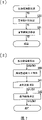
Fig. 2 is the flow chart of the image processing that relates to of this execution mode of expression.
Fig. 3 is the flow chart that the reducing noise in images of presentation graphs 2 is handled.
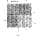
Fig. 4 is the key diagram of expression to the state on the additional border of pictorial data.
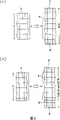
Fig. 5 is the key diagram of the state on laterally additional border, and (1) is the situation of the width of presentation image data when being multiples of width of block, and (2) are the situation of the width of presentation image data when not being the multiple of width of block.
Fig. 6 is the key diagram of the state on vertically additional border, and (1) is the situation of the height of presentation image data when being multiples of height of block, and (2) are the situation of the height of presentation image data when not being the multiple of height of block.
Fig. 7 is that the block clutter of Fig. 3 is removed the flow chart of handling, and (1) is the situation of expression to brightness component-part diagram image data, and (2) are the situation of expression to aberration component-part diagram image data.
Fig. 8 is that the block clutter is removed the key diagram of handling longitudinally, and (1) is the situation that Filtering Processing is carried out in expression, and (2) are that the situation of block clutter is longitudinally removed in expression.
Fig. 9 is that horizontal block clutter is removed the key diagram of handling, and (1) is the situation that Filtering Processing is carried out in expression, and (2) are the situations that horizontal block clutter is removed in expression.
Figure 10 is that the aberration component-part diagram image data to Fig. 3 carries out the key diagram that the block clutter is removed the upper limit lower limit tables of handling the aberration that uses.
Figure 11 is the key diagram that the aberration component-part diagram image data of Fig. 3 is carried out block clutter removing processing, (1) expression chromaticity difference diagram image data, (2) expression difference value data, (3) expression correction value data, (4) also represent the correction value data, the state that the pixel value of the pixel that (5) expression comes on the scene is replaced.
Figure 12 is that the mosquito clutter of presentation graphs 3 is removed the flow chart of handling.
Figure 13 is the key diagram that the edge image of expression Figure 12 makes processing.
Embodiment
At first, according to Fig. 1, tell about the image-processing system that relates to for a kind of execution mode of realizing method of reducing noise in images of the present invention.Image-processing system is made of computer, has CPU1, the ROM2, working storage 3, frame memory 4, data I/O device 5 and the hard disk 6 that are connected with bus 7 respectively.The ROM2 storage comprises the reducing noise in images program in interior computer program and various parameter, and working storage 3 is that CPU1 controls required memory, comprises buffer and register etc.CPU1 carries out various computings and processing according to the computer program of ROM storage.
As shown in Figure 2, when reducing noise in images is handled, at first carry out RGB/YCC conversion process (S1), carry out the reducing noise in images of block clutter, mosquito clutter then and handle (S2).In the RGB/YCC conversion process,, (R, G, B) pictorial data colour switching is become (Y, Cr, Cb) pictorial data according to following (formula 1)~(formula 3).Why transforming to the YCC color space, is that block clutter and mosquito clutter produce at this moment because the JPEC mode is carried out compression/de-compression with the YCC color space, handles so carry out reducing noise in images with identical color space, can improve the precision of correction.
Y?=(RToY[0][0]*R+RToY[0][1]*G+RToY[0][2]*B)/10000
Cr=(RToY[1][0]*R+RToY[1][1]*G+RToY[1][2]*B)/10000+2048
Cb=(RToY[2][0]*R+RToY[2][1]*G+RToY[2][2]*B)/10000+2048
(formula 1)~(formula 3)
Wherein, RtoY[i] [j]: the YCrCb conversion coefficient.
Reducing noise in images according to following (formula 4)~(formula 6), carries out YCC/RGB conversion process (S3) after handling (S2) end, thereby makes (Y, Cr, Cb) pictorial data recover (R, G, B) pictorial data, finishes a series of processing.
R=(YToR[0][0]*Y+YToR[0][1]*(Cr-2048)+YToR[0][2]*(Cb-2048)/10000
G=(YToR[1][0]*Y+YToR[1][1]*(Cr-2048)+YToR[1][2]*(Cb-2048)/10000
B=(YToR[2][0]*Y+YToR[2][1]*(Cr-2048)+YToR[2][2]*(Cb-2048)/10000
(formula 4)~(formula 6)
Wherein, YtoR[i] [j]: the YC attachment coefficient.
In addition, in the present embodiment, cause losing of data in order to suppress to handle, so the 8Bit data are expanded into 12Bit reprocessing (but still good with the 8Bit data processing).
As shown in Figure 3, in the reducing noise in images of S2 is handled, at first, add BORDER PROCESSING (S20), carry out the block clutter then and remove processing (S21), the mosquito clutter is removed and is handled (S22).Additional BORDER PROCESSING is for when the Filtering Processing that three data of the Y pictorial data of (Y, Cr, Cb) pictorial data (below be called " brightness component-part diagram image data "), Cr pictorial data and Cb pictorial data (following be called respectively " aberration component-part diagram image data ") are carried out hereinafter will telling about, the pictorial data in the border of interpolation pictorial data and the processing carried out.
Specifically, as Fig. 4 (is certain pictorial data, a square is represented pixel, the numeric representation pixel value) shown in, the border additional treatments of S20, be border S to pictorial data A (part that does not have mesh point), laterally, the vertical onesize block B ' (the thick frame that the mesh point part is arranged) of the additional respectively block B that relates to coding and decoding (the thick frame that does not have the mesh point part), and with its block B ' that adds of pixel value landfill of the pixel in the border of pictorial data ... the processing of pixel value.Be somebody's turn to do the block B ' that adds, if after the block clutter is removed processing (S21), mosquito clutter removing processing (S22) end, just eliminate processing (S23) and remove with the border.
In addition, if the lateral length of pictorial data A (number of picture elements) W be the multiple of the lateral length (number of picture elements) of block B, promptly be 8 multiple, so just as Fig. 5 (1) shown in, by additional border so that make each capable total length (number of picture elements) become [W+16]; And if not 8 multiple, so just as Fig. 5 (2) shown in, by additional border so that make the total length (number of picture elements) of each row become [W+ (8-(W mod 8))+16], thereby also to not intact block B " to carry out data additional.
Equally, if the longitudinal length of pictorial data A (number of picture elements) H be the multiple of the longitudinal length (number of picture elements) of block B, promptly be 8 multiple, so just as Fig. 6 (1) shown in, by additional border so that the total length (number of picture elements) that each is listed as becomes [H+16]; And if not 8 multiple, so just as Fig. 6 (2) shown in, by additional border so that make the total length (number of picture elements) of each row become [H+ (8-(H mod 8))+16], thereby also to not intact block B " to carry out data additional.
The block clutter of S21 is removed and is handled, be to brightness component-part diagram image data Y0, shown in Fig. 7 (1), carry out block clutter removing longitudinally and handle (S30), after making brightness component-part diagram image data Y1, carry out horizontal block clutter again and remove processing (S31), make brightness component-part diagram image data Y2 (the 1st brightness component-part diagram image data that the present invention relates to); And to each of aberration component-part diagram image data Cr0, Cb0, then shown in Fig. 7 (2), carry out aberration upper limit lower limit tables make processing (S40) afterwards, carry out watering down processing (S42) again longitudinally and making aberration component-part diagram image data Cr2, Cb2 (the 1st aberration component-part diagram image data that the present invention relates to) after horizontal tint reduction handles (S41) and make aberration component-part diagram image data Cr1, Cb1.
<vertically the block clutter is removed and is handled (S30) 〉
With the pixel in the border between block, as the pixel that comes on the scene, apply horizontal one-dimensional filtering, make the brightness component-part diagram image data Y1 of the horizontal luminance difference (smoothedization) in the border of having eliminated between block by brightness component-part diagram image data Y0.Filter size, for example can be set at 3 pixels and 5 pixels and (consult Fig. 8 (1), dense mesh point C represents the pixel that comes on the scene, light mesh point D represents filter range, lighter mesh point E represents Filtering Processing object pixel), use following (formula 7), carry out Filtering Processing (the 1st Filtering Processing that the present invention relates to).
[several 1]
This filter, be by to the matrix F b of the coefficient big (about 10~20 times) of in addition pixel (for example: the weighting filter of Chan Shenging Fb=(1 3 1)) to the coefficient ratio of the pixel that comes on the scene, be to be the center with the pixel C that comes on the scene, get summation after the coefficient of matrix F b and each pixel value (Yi) in the filter range multiplied each other, and remove the calculating formula of this summation with the summation of the coefficient of matrix F b.
But, above-mentioned Filtering Processing is an object with the border between the block only, so behind the overdilution, the border between the block just becomes ambiguous not nature (discontinuous) block, has strengthened the block clutter on the contrary.In addition, the border between some blocks is bright, when the border between other blocks is dim, through after the Filtering Processing, will forms above crossing of original pixel value and revise.Therefore in above-mentioned (formula 7), use the value behind the amplitude limit (handling at interval), so that satisfy following (formula 8) (that is: make and the absolute value of the difference of the pixel value of the pixel C that comes on the scene is included in the critical value b).
Yi[x, y]-b≤Yi ' [x-1, y]≤Yi[x, y]+b ... (formula 8)
Critical value b, if be 30, so, through after the above-mentioned Filtering Processing, the pixel value of the pixel E in the border between block just is transformed into Fig. 8 (2) by Fig. 8 (1), poor (luminance difference) of the pixel value in the border between block diminished as can be known.
<horizontal block clutter is removed and is handled (S31) 〉
With the pixel in the border between block, as the pixel that comes on the scene, apply one-dimensional filtering longitudinally, make the brightness component-part diagram image data Y2 of the luminance difference longitudinally (smoothedization) in the border of having eliminated between block by brightness component-part diagram image data Y1.Contents processing is handled identical in fact with block clutter removing longitudinally.
Critical value b, if be 30, so, the pixel value of the pixel E in the border between block just is transformed into Fig. 9 (2) by Fig. 9 (1), poor (luminance difference) of the pixel value in the border between block diminished as can be known.
Like this, above-mentioned two block clutters are removed and are handled, and are finally to weave into brightness component-part diagram image data Y2 (Fig. 9 (2)) by brightness component-part diagram image data Y0 (Fig. 8 (1)), have eliminated the processing of luminance difference on both direction in length and breadth.Because on visual characteristic, human eye is extremely responsive to brightness, and the block clutter is exactly mainly to result from luminance difference in the border between block, so removing, handle above-mentioned two block clutters, and be to remove extremely effectively handling of block clutter.But the block clutter not only results from luminance difference, also results from aberration in a way.Therefore, in order to remove the block clutter fully, the tint reduction that also needs to carry out telling about is below handled (S41, S42).
The upper limit tables of<aberration make processing (S40)
In tint reduction is handled, because use bigger filter (will tell about later), so behind the overdilution, color relation will be spread and sunk in to this.For example, red lip and skin interface place are carried out after big tint reduction handles, color relation will be spread and sunk in.Therefore, handle in (S41, S42), use the upper limit lower limit tables of aberration at tint reduction.
The upper limit lower limit tables of aberration is the table (consulting Figure 10) that calculates the value of blocking.C is the critical value that limits the use of under the upper limit of output aberration, gets 0~4095 scope.After adopting this table, belong to the input value of the scope of one c~c, be output identical value; Less than the input value of-c, whole output-c then; Greater than the input value of c, all export c.
<horizontal tint reduction is handled (S41) 〉
Each pixel of block as the pixel that comes on the scene, is applied horizontal one-dimensional filtering, make aberration component-part diagram image data Cr1, the Cb1 of horizontal tint reduction (smoothedization) by aberration component-part diagram image data Cr0, Cb0.Filter size for example can be set 7 pixels (consult Figure 11 (1), thick frame C represents the pixel that comes on the scene) for.
At first, poor (2047~2047) of the pixel value of the pixel C that calculating comes on the scene and near the pixel value of pixel, make difference value data (A) (Figure 11 (2)), give these difference value data (A) by upper limit lower limit tables (if critical value c is 15) make with higher limit, lower limit carry out amplitude limit correction value data (B) (Figure 11 (3)).Then, make the pixel value of this pixel C that comes on the scene revert to the pixel C that comes on the scene of these correction value data (B), after making correction value data (C) (Figure 11 (4)), use following (formula 9) to carry out Filtering Processing (the 3rd Filtering Processing that the present invention relates to) (Figure 11 (5)).
[several 2]
This filter, be that (Fc=1 1 for the equal matrix F c of coefficient ... 1) moving average filter of Chan Shenging, with the pixel C that comes on the scene is the center, after each correction values (Ci) of the coefficient of matrix F c and correction value data (C) multiplied each other, when getting its summation, also use the calculating formula of the summation (because be moving average filter, so the summation of coefficient equates with filter size) of the coefficient of matrix F c except that this summation.Each pixel is carried out this filter process one by one.
<tint reduction is handled (S42) longitudinally 〉
Each pixel of block as the pixel that comes on the scene, is applied one-dimensional filtering longitudinally, make aberration component-part diagram image data Cr2, the Cb2 of vertical tint reduction (smoothedization) by aberration component-part diagram image data Cr1, Cb1.Contents processing is handled identical in fact with horizontal tint reduction.
Like this, above-mentioned two tint reductions are handled, and are according to aberration component-part diagram image data Cr0, Cb0 (Figure 11 (1)), finally make aberration component-part diagram image data Cr2, Cb2, the profile that aberration is bigger is intactly keeping, and only waters down the processing of (elimination) less aberration.In other words, on the difference of aberration, do not establish under the upper limit and prescribe a time limit, owing to become with watering down that common rolling average is carried out, so the bigger profile of aberration has also been watered down.And by critical value c is set, upper limit lower limit is included in the mobility scale of difference of less aberration, thereby the difference of the aberration that the big profile of periphery is produced is replaced as the mobility scale of difference of the aberration of smaller profile, prevents that the bigger profile of aberration from being watered down.Result from the block clutter of aberration, as occurrence cause,, above-mentioned two tint reductions are handled with this less aberration, and being can not influence image quality to remove (image quality descends not obvious) and result from effective processing of block clutter of aberration.In addition, the intensity adjustment is carried out after can suitably setting the critical value of the filtering size of filter and upper limit lower limit tables.
The mosquito clutter of S22 is removed and is handled, as shown in figure 12, be after the brightness component-part diagram image data Y2 that the block clutter removing processing to S21 makes carries out brightness desalination processing (S50), when making brightness component-part diagram image data Y3 (the 2nd brightness component-part diagram image data), also carrying out the edge graph image data according to brightness component-part diagram image data Y2 makes processing (S51) and makes edge graph image data E1, then carry out edge graph image data correcting process (S52) and make correction edge graph image data E2, at last, carry out the synthetic processing (S53) of this correction edge graph image data E2 and described brightness component-part diagram image data Y3, make brightness component-part diagram image data Y4 (the 3rd brightness component-part diagram image data).
(S50) handled in<brightness desalination 〉
With each pixel of block, the pixel as coming on the scene applies two-dimensional filtering, makes the brightness component-part diagram image data Y3 that (smoothedization) desalinated in brightness by brightness component-part diagram image data Y2.Filter size for example can be set at 3 * 3 pixels and 5 * 5 pixels, uses following (formula 10), carries out Filtering Processing (the 2nd Filtering Processing that the present invention relates to).
[several 3]
(formula 10)
This filter, it is the moving average filter that produces by the matrix F b that coefficient equates, be to be the center with the pixel C that comes on the scene, when getting its summation after the coefficient of matrix F b and each pixel value (Yi) in the filter range multiplied each other, obtain with the summation of the coefficient of matrix F b and remove the merchant of this summation and the pixel value of the pixel C that comes on the scene poor, will be with the calculating formula of the pixel value addition of [d/128] multiply each other with it long-pending and the pixel C that comes on the scene.D is intended to adjust the coefficient (watering down strength factor) that waters down intensity.In addition, why removing d with 128, is because in order to adapt to high speed, uses [128/100] to multiply by the cause that waters down strength factor d in advance.
<edge graph image data makes processing (S51) 〉
Use following (formula 11), make edge graph image data E (consulting Figure 13) with block B unit.
Wherein, amplitude limit becomes-2048~2047
E1=Y2-Y3 ... (formula 11)
In other words, edge graph image data E1 is that poor after each pixel value of the brightness component-part diagram image data Y3 that makes handled in brightness desalination that each pixel value with brightness component-part diagram image data Y2 deducts S50.
<edge graph image data correcting process (S52) 〉
At first,, obtain its difference SA, use following (formula 12), make and revise edge graph image data E2 according to maximum difference value among the edge graph image data E1 and lowest difference score value.
[several 4]
SA≤e → E2=E1* (1/g) ... (formula 12)
When differing from SA greater than critical value e, mean the profile that exists luminance difference bigger in the image, the possibility that the mosquito clutter occurs is very big.The starting point of at this moment above-mentioned (formula 12) is as follows.That is: appear at the violent position of luminance difference owing to the mosquito clutter, thus deduct or add the difference value separately of edge graph image data E1 with the pixel edge adjusted value f of mosquito clutter, so that its absolute value (luminance difference of this point) is diminished.Why with all difference values of edge graph image data E1 as revising object (promptly also revising) even without the part that produces the mosquito clutter, be because in block retouch and not retouch all sometimes, the easy eye-catching cause in its border.But, in the difference value of edge graph image data E1, to its absolute value less than pixel edge adjusted value f, then as 0, revise in order to avoid cross.
When differing from SA, promptly in image the little smooth block of profile less than critical value, but because the possibility that the mosquito clutter occurs not is not have fully, so the starting point of at this moment above-mentioned (formula 12) is as follows.That is: all multiply by each difference value of edge graph image data E1, dwindle brightness on the whole with [the pixel edge adjusted value g of 1/ common image].But, SA compares during greater than critical value with difference, and minification is loose.
If critical value e is 10, if the pixel edge adjusted value g of the pixel edge adjusted value f of mosquito clutter and common image is 5.In Figure 13, difference SA is because be 179, so the noticeable pixel in the upper left corner (difference value-4) becomes 4-5=-1 → 0 after the correction so; Its adjacent noticeable pixel (difference value-28) becomes after the correction-28+5=-23; The noticeable pixel in its lower right corner (difference value 7) becomes 7-5=2 after the correction.Make out the correction edge image E2 that dwindles luminance difference on the whole.
<synthetic handle (S53) 〉
Use the synthetic processing of following formula (formula 13), make brightness component-part diagram image data Y4.But want amplitude limit to become 0~4096.
Y4=Y3+E2 ... (formula 13)
That is: brightness component-part diagram image data Y4 is the pixel value separately of brightness component-part diagram image data Y3, with the addition of correction value separately of the correction edge image E2 that makes in the edge of the S52 image correcting process and.
Like this, described mosquito clutter is removed and is handled, and finally weaves into brightness component-part diagram image data Y4 according to brightness component-part diagram image data Y2 exactly, and the bigger profile of luminance difference is watered down significantly (because original luminance difference is bigger, so water down not eye-catching), the processing that only waters down (elimination) trickle luminance difference.The reason that produces because of the mosquito clutter is this trickle luminance difference, is not influence effective processing that image quality is not removed the mosquito clutter (image quality is obviously descended) so above-mentioned mosquito clutter is removed processing.
But, the reducing noise in images that this example relates to is handled, and is to carry out the block clutter earlier to remove processing (S21), carries out the mosquito clutter then and removes processing (S22).Its reason is: the removing of mosquito clutter is handled (S22) and is watered down processing, removes processing (S22) if carry out this mosquito clutter earlier, and the block clutter will be watered down by whole, removes in the processing (S21) at the block clutter, removes with regard to being difficult to only to aim at the block clutter.Like this, need carry out block clutter removing processing (S21) and carry out mosquito clutter removing processing (S22) afterwards again.
In addition, the present invention is not limited to above-mentioned execution mode, can carry out various changes in the scope that does not break away from aim of the present invention.
For example: in the above-described embodiment, the tint reduction of S41, S42 is handled, as the processing in the block clutter removing processing of S21, but as mentioned above, has the effect that waters down (elimination) aberration smaller portions, also effective to the mosquito clutter, so the processing of all right and S40 is together, as the processing in the mosquito clutter removing processing of S22.Generally speaking, if the aberration component-part diagram image data of pictorial data is implemented the processing of S40~S42, the visual clutter in the aberration component-part diagram image data promptly is eliminated, and does not have special implication so give its position.
In addition, in the above-described embodiment, in the tint reduction of S41, S42 is handled, use the one-dimensional filtering device.This is because the filtering size of filter is big, in order not spend the cause in processing time.If but no matter the processing time, or the filtering size is little, also can use two dimensional filter.The filter that the block clutter of S30, S31 uses in removing and handling also is not limited to the one-dimensional filtering device, for example, can use the two dimensional filter of 3 * 3 pixels.
In addition, in the above-described embodiment, remove in the processing, use weighting filter, in processing in addition, use moving average filter at the block clutter of S30, S31.But be not limited to this.
In addition, in the above-described embodiment, carry out reducing noise in images on computers and handle, but the code translator of also can packing into, (being behind inverse orthogonal transformation specifically) carries out the reducing noise in images processing among decoding is handled.
In addition, in the above-described embodiment, when being deciphered, compressed image comprises the RGB conversion process, so carry out RGB/YCC conversion process (S1).Undoubtedly, input imagery is if having the BMP image of RGB information, need this RGB/YCC conversion process, and if the original jpeg picture that just has YCC information just may not need RGB/YCC conversion process (S1) to reach the YCC/RGB conversion process (S3) that accompanies with it.
Claims (10)
1, a kind of method of reducing noise in images is removed the block clutter and the mosquito clutter that produce when deciphering with the image of block unit's compressed encoding, it is characterized in that:
Each of brightness component-part diagram image data in the pictorial data and aberration component-part diagram image data is divided into the block identical with coding and decoding,
To brightness component-part diagram image data, have: carry out making operation the 1st brightness component-part diagram image data of the edge smoothingization between the block with the 1st Filtering Processing of the pixel separately in the border between the block as the pixel that comes on the scene;
The pixel separately of the 1st brightness component-part diagram image data is carried out the 2nd Filtering Processing as the pixel that comes on the scene, make operation the 2nd brightness component-part diagram image data of whole smoothing;
Make pixel value separately with the 1st brightness component-part diagram image data and deduct the operation of edge graph image data of the pixel value separately of the 2nd brightness component-part diagram image data;
Make operation according to the correction edge graph image data of the difference value separately of institute's this edge graph image data of fixed condition correction; And
Make and will revise the operation of the 3rd brightness component-part diagram image data of the pixel value addition separately of the correction value separately of edge graph image data and the 2nd brightness component-part diagram image data,
And to aberration component-part diagram image data, have: with this aberration component-part diagram image data pixel separately,, carry out the 3rd Filtering Processing, make the operation of the 1st aberration component-part diagram image data that makes whole smoothing as the pixel that comes on the scene.
2, method of reducing noise in images as claimed in claim 1, it is characterized in that: described the 1st Filtering Processing, use the value of amplitude limit so that make the absolute value of difference of the pixel value of the pixel value of the pixel that comes on the scene and the pixel in the filter range, include in the fixed critical value.
3, method of reducing noise in images as claimed in claim 1 or 2, it is characterized in that: the making of described correction edge graph image data, be according to maximum difference value in the described edge graph image data and lowest difference score value, obtain the poor of them, difference greater than during fixed critical value, with 0 as lower limit, use fixed adjusted value plus-minus edge graph image data difference value separately so that its absolute value diminishes.
4, method of reducing noise in images as claimed in claim 3 is characterized in that: described correction edge graph image data, described difference less than during fixed critical value, by with fixed adjusted value and edge graph image data difference value separately make after multiplying each other.
5, method of reducing noise in images as claimed in claim 1 or 2, it is characterized in that: described the 3rd Filtering Processing, handle at the correction value data that make behind the amplitude limit, described correction value data be use fixed upper limit lower limit tables, the difference value data that the difference of the pixel value of the pixel value of the pixel that comes on the scene by calculating and the pixel in the filter range is made carry out weaving into behind higher limit, the lower limit amplitude limit.
6, method of reducing noise in images as claimed in claim 3, it is characterized in that: described the 3rd Filtering Processing, handle at the correction value data that make behind the amplitude limit, described correction value data be use fixed upper limit lower limit tables, the difference value data that the difference of the pixel value of the pixel value of the pixel that comes on the scene by calculating and the pixel in the filter range is made carry out weaving into behind higher limit, the lower limit amplitude limit.
7, method of reducing noise in images as claimed in claim 4, it is characterized in that: described the 3rd Filtering Processing, handle at the correction value data that make behind the amplitude limit, described correction value data be use fixed upper limit lower limit tables, the difference value data that the difference of the pixel value of the pixel value of the pixel that comes on the scene by calculating and the pixel in the filter range is made carry out weaving into behind higher limit, the lower limit amplitude limit.
8, method of reducing noise in images as claimed in claim 5 is characterized in that: described fixed upper limit lower limit tables, for absolute value less than the input value of fixed critical value, then with it as output valve; And for absolute value more than or equal to the input value of fixed critical value, then will be with input value with the critical value of symbol as output valve.
9, method of reducing noise in images as claimed in claim 6 is characterized in that: described fixed upper limit lower limit tables, for absolute value less than the input value of fixed critical value, then with it as output valve; And for absolute value more than or equal to the input value of fixed critical value, then will be with input value with the critical value of symbol as output valve.
10, method of reducing noise in images as claimed in claim 7 is characterized in that: described fixed upper limit lower limit tables, for absolute value less than the input value of fixed critical value, then with it as output valve; And for absolute value more than or equal to the input value of fixed critical value, then will be with input value with the critical value of symbol as output valve.
Applications Claiming Priority (2)
| Application Number | Priority Date | Filing Date | Title |
|---|---|---|---|
| JP2003400421 | 2003-11-28 | ||
| JP2003400421A JP4066367B2 (en) | 2003-11-28 | 2003-11-28 | Image noise removal method |
Publications (2)
| Publication Number | Publication Date |
|---|---|
| CN1622633A CN1622633A (en) | 2005-06-01 |
| CN100340117C true CN100340117C (en) | 2007-09-26 |
Family
ID=34544876
Family Applications (1)
| Application Number | Title | Priority Date | Filing Date |
|---|---|---|---|
| CNB2004100946908A Expired - Fee Related CN100340117C (en) | 2003-11-28 | 2004-11-12 | Method of reducing block and mosquito noise (effect) in images |
Country Status (4)
| Country | Link |
|---|---|
| US (1) | US7415163B2 (en) |
| EP (1) | EP1549075A3 (en) |
| JP (1) | JP4066367B2 (en) |
| CN (1) | CN100340117C (en) |
Families Citing this family (17)
| Publication number | Priority date | Publication date | Assignee | Title |
|---|---|---|---|---|
| JP4457346B2 (en) * | 2004-11-12 | 2010-04-28 | ノーリツ鋼機株式会社 | Image noise removal method |
| JP4661238B2 (en) * | 2005-01-31 | 2011-03-30 | コニカミノルタホールディングス株式会社 | Image processing method, image processing apparatus, and image processing program |
| JP3895357B2 (en) * | 2005-06-21 | 2007-03-22 | 日東光学株式会社 | Signal processing device |
| KR100820813B1 (en) * | 2005-08-10 | 2008-04-10 | 엘지전자 주식회사 | Apparatus for removing noise-image |
| TWI296099B (en) * | 2005-12-15 | 2008-04-21 | Princeton Technology Corp | Method for improving image quality and image processor of operating the same |
| JP4455487B2 (en) * | 2005-12-16 | 2010-04-21 | 株式会社東芝 | Decoding device, decoding method, and program |
| US8224076B2 (en) * | 2006-11-29 | 2012-07-17 | Panasonic Corporation | Image processing method and image processing apparatus |
| US8571347B2 (en) | 2008-09-09 | 2013-10-29 | Marvell World Trade Ltd. | Reducing digital image noise |
| US8442348B2 (en) * | 2008-11-06 | 2013-05-14 | Seiko Epson Corporation | Image noise reduction for digital images using Gaussian blurring |
| US8306355B2 (en) * | 2009-07-13 | 2012-11-06 | Sharp Laboratories Of America, Inc. | Methods and systems for reducing compression artifacts |
| US8615141B2 (en) * | 2009-08-10 | 2013-12-24 | Seiko Epson Corporation | Systems and methods for motion blur reduction |
| JP4703759B2 (en) * | 2009-11-27 | 2011-06-15 | 株式会社東芝 | Image processing apparatus and image processing method in the same |
| EP2599311B1 (en) | 2010-07-28 | 2020-02-05 | Synaptics Incorporated | Block compression artifact detection in digital video signals |
| JP5682545B2 (en) * | 2011-11-29 | 2015-03-11 | ブラザー工業株式会社 | Image processing device |
| JP6396946B2 (en) * | 2016-06-02 | 2018-09-26 | Hoya株式会社 | Image processing apparatus and electronic endoscope system |
| JP6696361B2 (en) * | 2016-08-31 | 2020-05-20 | コニカミノルタ株式会社 | Image processing apparatus, image forming apparatus and program |
| JP6794858B2 (en) * | 2017-02-06 | 2020-12-02 | コニカミノルタ株式会社 | Image processing device and image processing method |
Citations (9)
| Publication number | Priority date | Publication date | Assignee | Title |
|---|---|---|---|---|
| CN1134088A (en) * | 1995-02-28 | 1996-10-23 | 大宇电子株式会社 | Method for removing blocking effect for use in video signal decoding apparatus |
| CN1170318A (en) * | 1996-07-06 | 1998-01-14 | 三星电子株式会社 | Loop filtering method for reducing group effect of moving compensation image and ringing noise |
| CN1174478A (en) * | 1996-05-14 | 1998-02-25 | 大宇电子株式会社 | Method and apparatus for removing blocking effect in motion picture decoder |
| JPH10164576A (en) * | 1996-11-29 | 1998-06-19 | Kyocera Corp | Image decoder |
| JPH10191335A (en) * | 1996-12-27 | 1998-07-21 | Sony Corp | Block distortion reducing method and device |
| US5819035A (en) * | 1995-10-20 | 1998-10-06 | Matsushita Electric Industrial Co., Ltd. | Post-filter for removing ringing artifacts of DCT coding |
| CN1264482A (en) * | 1997-07-16 | 2000-08-23 | 三星电子株式会社 | Signal adaptive filtering method,signal adaptive filter and computer readable medium for storing program therefor |
| US6360024B1 (en) * | 1997-02-07 | 2002-03-19 | Matsushita Electric Industrial Co., Ltd. | Method and apparatus for removing noise in still and moving pictures |
| US6594400B1 (en) * | 1998-08-31 | 2003-07-15 | Lg Electronics Inc. | Method of removing block phenomenon and ring phenomenon in compression coded image |
Family Cites Families (7)
| Publication number | Priority date | Publication date | Assignee | Title |
|---|---|---|---|---|
| JPH11250246A (en) * | 1998-02-27 | 1999-09-17 | Fuji Photo Film Co Ltd | Image processing method and image processor |
| US6285801B1 (en) * | 1998-05-29 | 2001-09-04 | Stmicroelectronics, Inc. | Non-linear adaptive image filter for filtering noise such as blocking artifacts |
| US6973221B1 (en) * | 1999-12-14 | 2005-12-06 | Lsi Logic Corporation | Method and apparatus for reducing block related artifacts in video |
| US6845180B2 (en) * | 2001-03-16 | 2005-01-18 | Sharp Laboratories Of America, Inc. | Predicting ringing artifacts in digital images |
| RU2342703C2 (en) * | 2003-09-23 | 2008-12-27 | Томсон Лайсенсинг | Method of simulating graininess of film through frequency filtering |
| JP2005167399A (en) * | 2003-11-28 | 2005-06-23 | Noritsu Koki Co Ltd | Image noise eliminating method |
| JP4457346B2 (en) * | 2004-11-12 | 2010-04-28 | ノーリツ鋼機株式会社 | Image noise removal method |
-
2003
- 2003-11-28 JP JP2003400421A patent/JP4066367B2/en not_active Expired - Lifetime
-
2004
- 2004-11-12 CN CNB2004100946908A patent/CN100340117C/en not_active Expired - Fee Related
- 2004-11-23 US US10/996,229 patent/US7415163B2/en not_active Expired - Fee Related
- 2004-11-26 EP EP20040106104 patent/EP1549075A3/en not_active Withdrawn
Patent Citations (9)
| Publication number | Priority date | Publication date | Assignee | Title |
|---|---|---|---|---|
| CN1134088A (en) * | 1995-02-28 | 1996-10-23 | 大宇电子株式会社 | Method for removing blocking effect for use in video signal decoding apparatus |
| US5819035A (en) * | 1995-10-20 | 1998-10-06 | Matsushita Electric Industrial Co., Ltd. | Post-filter for removing ringing artifacts of DCT coding |
| CN1174478A (en) * | 1996-05-14 | 1998-02-25 | 大宇电子株式会社 | Method and apparatus for removing blocking effect in motion picture decoder |
| CN1170318A (en) * | 1996-07-06 | 1998-01-14 | 三星电子株式会社 | Loop filtering method for reducing group effect of moving compensation image and ringing noise |
| JPH10164576A (en) * | 1996-11-29 | 1998-06-19 | Kyocera Corp | Image decoder |
| JPH10191335A (en) * | 1996-12-27 | 1998-07-21 | Sony Corp | Block distortion reducing method and device |
| US6360024B1 (en) * | 1997-02-07 | 2002-03-19 | Matsushita Electric Industrial Co., Ltd. | Method and apparatus for removing noise in still and moving pictures |
| CN1264482A (en) * | 1997-07-16 | 2000-08-23 | 三星电子株式会社 | Signal adaptive filtering method,signal adaptive filter and computer readable medium for storing program therefor |
| US6594400B1 (en) * | 1998-08-31 | 2003-07-15 | Lg Electronics Inc. | Method of removing block phenomenon and ring phenomenon in compression coded image |
Also Published As
| Publication number | Publication date |
|---|---|
| JP4066367B2 (en) | 2008-03-26 |
| US7415163B2 (en) | 2008-08-19 |
| EP1549075A3 (en) | 2006-12-27 |
| US20050117812A1 (en) | 2005-06-02 |
| CN1622633A (en) | 2005-06-01 |
| EP1549075A2 (en) | 2005-06-29 |
| JP2005167393A (en) | 2005-06-23 |
Similar Documents
| Publication | Publication Date | Title |
|---|---|---|
| CN100340117C (en) | Method of reducing block and mosquito noise (effect) in images | |
| CN1774030A (en) | Method for reducing noise in images | |
| CN1622597A (en) | Method of reducing noise in images | |
| JP6490178B2 (en) | Multi-color channel multiple regression predictor | |
| RU2329536C2 (en) | Method and device to enhance quality of video image at low bit rates | |
| CN1110961C (en) | Post-filter for removing ringing artifacts of DCT coding | |
| US7302104B2 (en) | Smoothing tile boundaries of images encoded and decoded by JPEG 2000 | |
| CN106504281B (en) | Image quality enhancing and filtering method applied to cmos image sensor | |
| CN1652606A (en) | Method and apparatus for MPEG artifact reduction | |
| JP4360416B2 (en) | Image compression method, image compression apparatus, and program | |
| JP4987480B2 (en) | Conversion to remove image noise | |
| CN1874528A (en) | Method and apparatus for improving quality of composite video signal and method and apparatus for decoding composite video signal | |
| CN1960495A (en) | Picture coding device, method, and program thereof | |
| CN1531347A (en) | Image signal encoder and encoding method | |
| CN1246242A (en) | Improved estimator for recovering high frequency components from compressed image data | |
| CN1878308A (en) | Orthogonal transformation method for image and video compression | |
| CN1213600C (en) | N-dimensional filter and method for N-dimensionally filtering an original image | |
| US20230023387A1 (en) | Low complexity image filter | |
| CN1193618C (en) | Pre-processing method for motion estimation | |
| CN1934585A (en) | Electronic device and a method in an electronic device for processing image data | |
| CN1574977A (en) | Method and device for changing image size | |
| CN1720746A (en) | Method of measuring blocking artefacts | |
| JP2010251874A (en) | Encoded image correction device, and program of the same | |
| JP4331992B2 (en) | Image encoding method, image decoding method, image encoding device, image decoding device, program thereof, and program recording medium thereof | |
| Kadono et al. | Encoding of color still pictures by wavelet transform and vector quantization |
Legal Events
| Date | Code | Title | Description |
|---|---|---|---|
| C06 | Publication | ||
| PB01 | Publication | ||
| C10 | Entry into substantive examination | ||
| SE01 | Entry into force of request for substantive examination | ||
| C14 | Grant of patent or utility model | ||
| GR01 | Patent grant | ||
| C17 | Cessation of patent right | ||
| CF01 | Termination of patent right due to non-payment of annual fee |
Granted publication date: 20070926 Termination date: 20111112 |