CN100338902C - Method for raising time measurement resolutuin ratio and positioning in block network through time modulation - Google Patents
Method for raising time measurement resolutuin ratio and positioning in block network through time modulation Download PDFInfo
- Publication number
- CN100338902C CN100338902C CNB2004100708011A CN200410070801A CN100338902C CN 100338902 C CN100338902 C CN 100338902C CN B2004100708011 A CNB2004100708011 A CN B2004100708011A CN 200410070801 A CN200410070801 A CN 200410070801A CN 100338902 C CN100338902 C CN 100338902C
- Authority
- CN
- China
- Prior art keywords
- clock
- packet
- receiver
- network
- modulation signal
- Prior art date
- Legal status (The legal status is an assumption and is not a legal conclusion. Google has not performed a legal analysis and makes no representation as to the accuracy of the status listed.)
- Expired - Fee Related
Links
Images


Classifications
-
- H—ELECTRICITY
- H04—ELECTRIC COMMUNICATION TECHNIQUE
- H04L—TRANSMISSION OF DIGITAL INFORMATION, e.g. TELEGRAPHIC COMMUNICATION
- H04L7/00—Arrangements for synchronising receiver with transmitter
- H04L7/04—Speed or phase control by synchronisation signals
-
- H—ELECTRICITY
- H04—ELECTRIC COMMUNICATION TECHNIQUE
- H04J—MULTIPLEX COMMUNICATION
- H04J9/00—Multiplex systems in which each channel is represented by a different type of modulation of the carrier
-
- H—ELECTRICITY
- H04—ELECTRIC COMMUNICATION TECHNIQUE
- H04J—MULTIPLEX COMMUNICATION
- H04J3/00—Time-division multiplex systems
- H04J3/02—Details
- H04J3/06—Synchronising arrangements
- H04J3/062—Synchronisation of signals having the same nominal but fluctuating bit rates, e.g. using buffers
- H04J3/0632—Synchronisation of packets and cells, e.g. transmission of voice via a packet network, circuit emulation service [CES]
-
- H—ELECTRICITY
- H04—ELECTRIC COMMUNICATION TECHNIQUE
- H04L—TRANSMISSION OF DIGITAL INFORMATION, e.g. TELEGRAPHIC COMMUNICATION
- H04L27/00—Modulated-carrier systems
-
- H—ELECTRICITY
- H04—ELECTRIC COMMUNICATION TECHNIQUE
- H04J—MULTIPLEX COMMUNICATION
- H04J3/00—Time-division multiplex systems
- H04J3/02—Details
- H04J3/12—Arrangements providing for calling or supervisory signals
Abstract
A method of recovering timing information in a packet network is disclosed wherein a modulation scheme is used to transport additional information required for clock recovery between the sender and receiver across the network.
Description
Technical field
The present invention relates to digital communicating field, particularly relate to the method and apparatus that improves time measurement resolution in the packet network.
Background technology
Occurred at present a kind of telecommunications and data technique being merged into the trend of single environment, this is mainly owing to cost consideration.Optimization technique seemingly utilizes asynchronous network, and this is perhaps mainly owing to market penetration, and the fact of better quality technical scheme is not provided owing to asynchronous network.A particular aspects that produces the asynchronous network of telecommunication service problem is to lack the precision clock transmission.
There is the multiple mathematical method that addresses this problem at present.The typical scenario of usefulness is based on average, weighting, line fitting and combination thereof.Yet owing to have a large amount of problems in the network, therefore final solution is still limited.The character of these problems makes present network model and present enforcement be not enough to the accurately influence of processing time quantizer.Network model is paid close attention to chance, serve as thus to look like continuous time base, but this is not a correct hypothesis.
Disclose various prior art schemes at present, for example, people's such as Fleisher United States Patent (USP) US5 has described " the synchronous residence time of regularly recovering in the broadband networks stabs " for 260, No. 978; " clock synchronization of packet network that use does not have the SRTS of public network clock " described in No. the 0205350.2nd, the British patent of Gordon J.Reesor application; " use the fine particle network time synchronization of reference broadcast " and also be published in the Internet, the author is Jeremy Elson, and Lewis Girod and Deborah Estrin, addresses of items of mail are { jelson, girod, destrin}@cs.ucla.edu; " location of clock zone in the packet network " described in people's such as W.L.Repko patent application; " pulse rate spectral frequency synthesizer " appendix of Venceslav F.Kroupa is " in the Direct Digital frequency synthesis ", is published in IEEE, ISBN0-7803-3438-8; " oversampling delta sigma data converter, principle, design and the emulation " of James C.Candy and Gabor C.Temes is published in IEEE PRESS, ISBN0-87942-285-8.Above-mentioned file is intactly quoted, for your guidance.
The clock location need be via the network delivery real-time clock signal in the packet network.Data network is the main source that asynchronous network occurs, the purpose of this data network yes main Data transmission rather than time.The technology of using in the asynchronous network has been introduced the matter of time that occurs as variable time delay usually.They are pseudorandom for the general models supposition of these time delays.In fact, the character of time delay is more complicated, and is made up of error type and amplitude.
Asynchronous network is made up of the unit that runs on their clocks.Clock utilizes crystal to generate usually, so that rational stability is provided.The stability that digital circuit need move in circles is to guarantee settling time and retention time.The external interface clock is taken from crystal clock.This hint time quantization is defined by crystal, and crystal also makes time quantization relatively stable than long duration.If the sampling of the dual serial of these clocks, then effective difference of sampling frequency may be bigger, but also may be quite little.Latter event causes the low frequency aberration of the whole behavior of system.
Switch and router have the unit that can dispose professional statistical property, for example formation.Time delay has been introduced in this unit, and this depends on other business by switch/router, the perhaps inner business (normally management service) that generates.This time delay is normally pseudorandom, because it depends on other Business Stream himself environmental work.
Modern switch or router have built-in system, and this built-in system is often rearranged the accurate operation of exchange.For example, can change the priority of queue processing.When the exchange configuration becomes complexity, this will become more obvious.For example professional changing its course means the bigger jump of time delay.According to accurate operation, it can be very coherent that time delay changes, and as the result who repeats regularly to upgrade, perhaps, if time delay mainly relies on other stream, then can be pseudorandom for example.
In switch, can carry out the processing of low frequency aspect, such as conventional internal maintenance.This built-in function can have some impact to effective time delay.If these time delays appear in the subsequent node with different slightly frequencies, this will become complicated more.
The network phenomenon of switch and terminate load is the mixing of all above influences.When thick observation, queuing delay is overriding, and this description standard scheme has the pseudorandom model.When further observation, will find to present certain regularity.The first order is the influence of built-in function, the quantized level that the phy clock that better level will be the unit causes.In the minimum level of Δ, it is obvious that thermal noise will become.
As for the time delay size, Different Effects has been introduced their typical problem.Queuing delay can be the pseudorandom of time, but it is probably by some size dominations that relate to typical data bag size.Like this, queuing delay also can carry the frequency that some typical time delays change.Structuring unit more ironically.It will be appreciated that on lower frequency the time delay that internal control causes changes.Clock skew can be positioned on the low-down frequency (if the clock difference is little) or be positioned at (for than the scale clock difference) on the higher frequency.
In order to obtain best possible performance, clock recovery method should be handled these influences.Existing scheme concentrates on the thick grade, rather than on the better grade, and the scheme that is used for thick grade is provided.Common this scheme relies on the relative stability of local oscillator than the go-between behavior.The knowledge of stable local oscillator is suitably to suppress the minimum requirements of pseudorandom influence.But but when the scheme time spent of these grades, first next problem grade just becomes obviously and is overriding.Therefore, the quantification gradation that clock is introduced in the network becomes the mastery factor, and to this, the pure stability of the local oscillator of terminal node can not provide sufficient solution.
Summary of the invention
The present invention is devoted to occur in the quantification gradation in the network element.The present invention depends on the stability of local oscillator, but has increased the characteristic of transmit leg, and this transmit leg can be configured to improve the recovery precision the recipient.
In better grade, thermal noise only can utilize routine on average to handle, and this thermal noise is relatively for a short time makes it have insignificant impact.
The present invention is devoted to the precise characteristics of time quantization device, and proposes the simple and first-class solution of dealing with problems with the modulation format of markers packet or incident.
According to the present invention, a kind of method of recovering timing information in the packet network is provided here, wherein modulation signal is used for being delivered between the transmitter of network and the receiver and is used for the required additional information of clock recovery.
Adjustment can take to send the form of the rate variation of packet.All the time delay group can be divided into pseudorandom part and structuring part.Although existing solution can be handled the pseudorandom problem that the clock of asynchronous network transmits, these solutions are limited to the grade of structure problem.Its reason is that the structuring unit has very low frequency problem, and this problem is difficult to handle well.The present invention has increased the modulation as an information.This can be regarded as being similar to the pilot tone of using in the rf modulations (FM).The size of the modulation that is increased and frequency aspect are the important parameters that can influence system performance.
In most realistic system, modulation will be shared as one of parameter of the many continuous transmission that are used for carrying out synchronous communication (dynamically), perhaps become of constant (semi-static) and be provided with to share as transmitting and being left, perhaps be provided with inherently in the method, make it become hardware or software (static state).Show and, it is normally the most attractive, first to substitute (in all the other schemes of suggestion one) owing to many reasons, but solution limited space system, such as available horsepower.
The present invention also provides the equipment that is used for recovering via packet network timing information on receiver, and this equipment comprises: be positioned at a modulator at transmitter place, this transmitter sends modulation signal via the network that transmits timing information; With a clock recovery unit that is positioned at the receiver place, use described modulation signal to improve the precision of recovered clock.
Brief Description Of Drawings
Below with reference to the accompanying drawings, and only mode illustrates in greater detail the present invention by way of example.
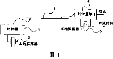
Fig. 1 illustrates transmitter and the receiver via Ethernet (Ethernet) communication;
Fig. 2, Fig. 3 and Fig. 4 are various input and output clock-timed sequential charts;
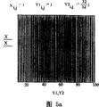
Fig. 5 a to Fig. 5 e is moire figure;
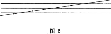
Fig. 6 illustrates the mathematics of one little modulation signal;
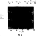
Fig. 7 illustrates the reticulate pattern figure when lines among Fig. 6 are less to tilt;
Fig. 8 illustrates the schematic diagram of ethernet environment solution.
Embodiment
The character of structuring quantization influence at first is discussed.In first example, suppose in packet network, only to have two Ethernet cards (plug-in unit), have the intermediate interdigitated link, promptly there is not switch/router.In this environment, it is not difficult avoiding quantification problem; Simple PLL can recover from a card and be subordinated to the frequency of another card.The mode that this PLL will adopt time delay to become very little forces clock to be equal to each other.Yet on many nodes, this solution is infeasible, because the possibility of the exchange of this scheme refusal and the independent clock in the middle of each.PLL provides the synchronous detecting scheme, but can not carry out by force on many quantification nodes, unless each node is carried out the synchronous detecting scheme.
In Fig. 1, the clock source 1 with local oscillator 2 of grid line 3 near-ends communicates with local oscillator 5 related clock copied cellses 4 with grid line 3 far-ends.Correction term can be used for closing PLL ring, and local sampling clock becomes and is synchronized with clock source local oscillator signals.Should not feed back, synchronous detecting is impossible.
If two clock independent operatings, and roughly be positioned at same frequency, it is available that then last sampling clock will determine when signal becomes effectively, but first clock will determine when suppling clock, as shown in Figure 2.Can set up timing error like this.
Last column among Fig. 2 has shown the error on the y axle, it as two clocks each other quite near the time the function of time.The frequency of input clock (input of asynchronous channel) is higher than the frequency of output clock (output is meant the sampling to asynchronous channel output), thereby causes the not enough potential problems of sampling, and this can see on the right side of figure.
It is not closer to each other that Fig. 3 has shown at clock, but has occurrence under the situation of frequency ratio of 2: 1 and 1: 2 respectively.Fig. 3 has many positions that the not enough problem of sampling will take place.Make the output clock of upper frequency obtain result shown in Figure 4, then no longer stand the not enough problem of sampling.
Obviously, timing error can 0 to almost with output the same big scope of clock cycle in.This is real, because input clock is very accurate; Its benchmark is provided with regularly desirable.Output clock this clock of sampling again, thus mistake introduced.Fig. 4 provides minimal error, because the output clock has highest frequency.Therefore error can be regarded as the result of modulo operator, temporal calculation, because modulus equals to export the grid of clock.
Error frequency is obviously higher in Fig. 4.This output clock with " blocking " input clock is relevant, and wherein less truncation part (less modulus) refers to upper frequency.
Because modulo operator, sample process are known as the 0th rank noise shaping and handle.The delta sigma reshaper uses modulo operator and a large amount of integrator under this 0 situation.If the output clock is made up of the clock of PLL regeneration, then the integrator among the PLL (VCO, CCO, DCO or analog) will make this ring become one first rank noise reshaper.This provides a good link with conventional delta sigma technology.PLL as frequency measuring equipment produces than the better speed of calculator/precision product.
The crucial formula of understanding clock rate is as follows:
CyclePeriod?2=n*CyclePeriod?1+m*CyclePeriod?1,n∈N,0≤m<1
Wherein, CyclePeriod 1 is the cycle of first clock, and CyclePeriod 2 is cycles of the second clock of sampling first clock.
Understand digital m and determine that the effective speed that changes is important.If m is very near 0 or 1, the time error that then obtains will increase or dwindle lentamente, until the final wraparound of time error.In time domain, this seems a sawtooth, as from this example see.The minimum frequency of error may be extremely low, and this frequency is influenced by two clocks.
The sampling clock of supposing output signal is the 10MHz normal value, and actual error is 0ppm.Suppose that this clock extracts and has+first benchmark of the 1MHz of 1ppm error.Above-mentioned formula shows the sub-fraction error of in fact discovering 10ppm with the output sampling device of 10 times of speed operations, the i.e. 10ppm of per sampling period.These will be in 100.000 cycles of benchmark " filling ", i.e. in 0.1 second " filling ".Like this, error will be a zigzag, and be the fundamental tone that is about 10Hz.
Suppose that identical sampling clock is used for extracting the 10kHz clock with the 1ppm error again.Ratio between the quantity is a factor 1000 now, so perceptible circular error will be 1000ppm now.These will be 1000 cycles, promptly in 0.1 second " filling ".Frequency is still identical.
The supposition sampled signal is 10Hz now, 1ppm.In 0.1 second, this signal will move one second 0.1ppm, i.e. 100 nanoseconds (ns).But this equals a sampling period.Error will not be a zigzag, but flat condition.Error becomes DC basically, this means that the 10MHz clock may shift out for 100 nanoseconds, rather than samples with different pattern.
Therefore can see that error spectrum depends on the accurate ratio of clock.It especially can change between sawtooth and other DC.Importantly, found the optimal spectrum possibility, normally high frequency.This suppresses error percentage easily, and accurately follows the minor clock variation, is about near DC.
Suppose sampled signal has still large deviation near 1MHz speed.1 cycle is 10MHz sampling clock (10+5/32) cycle, promptly is about 1.6% of 1MHz.Value 5/32 assurance sampling error mainly is made up of the high frequency item.This is the indirect consequence that obtains from the Engel Series that revises, wherein 5/32 and its remainder 1-5/32=27/32 produce highest frequency component.The easier filtering of these high frequencies.For example, so all multiple digital decimate easily.This analysis and suggestion extracts the frequency of the second clock of first clock should be high as far as possible, and period-luminosity relation will to make the digital m of following formula be a strange mark, as 5/32 or 27/32.To fall into 10MHz (100 period nanosecond) although this problem is the minimum frequency of typically sampling, regularly the typical data packet rate that can be transmitted fully will be low, for example the order of magnitude of 10-100 packets/second.This makes that clock ratio is 100 ten thousand the order of magnitude, and it still is the order of magnitude of clock accuracy size.Therefore, it becomes and is difficult to finely tune sampling frequency, makes it have ideal characterisitics.
Determine that by clock ratio the thought of performance can be presented in some moire patterns.In Fig. 5 a to Fig. 5 e, shown a plurality of examples of two clocks that are used to have different ratios, this can read from the formula near actual pattern.In the drawings, clock is the simple vertical line, has described sampling time.Density graphical display error be error in relatively low frequency or the upper frequency.By FFT (fast fourier transform), can obtain the picture rich in detail of optimum performance, it can be shown as and be about 32/27 ratio.Other moire pattern has the longer time displacement, comprises DC.The latter is quite tangible for ratio 32/32 and 32/16, and also is very tangible for ratio 32/24.The moire example can be tuning by any size of space.
In fact, have switch, router and analog in the packet network, these nodes can not easily be worked with input clock.Have more than one input clock signal, which clock these signals do not provide best information especially, and the output stream that forms depends on the global clock of node or depends on relevant inlet flow.This means, will always exist certain to sample again between two streams, even end point has been utilized PLL.This PLL only is used for making optimum signal to recover to become possibility, rather than is used for clock distribution.Can and will increase from the clock quantity that node-to-node comprised, and make the quantity of clock ranges migration greater than (more greater than) so far described single migration.
If adopt paired equipment, then the analysis of two clocks is still effective.Therefore, can regard the increase of timing error as from the overall delay that is input to output from each paired equipment.
Minimum clock in this link will provide the error of worst case usually.If an equipment uses grid effective time of 8kHz, and remaining all devices uses 10MHz, and then 8kHz frame rate [125 microseconds (μ s) grid] will be overriding.Domination will be presented in absolute time error size and the frequency spectrum.
If clock rate is comparable, then error general with present the noise additivity and handle very incoherent.Especially, when comprising many nodes, this will keep.This has the direct result of the behavior in the frequency spectrum.
The variation of time grid depends on network configuration usually.For example, do not wish that Ethernet has the time grid more worse than 100 nanoseconds (for the 10Mbit/s Ethernet).The typical grid (byte repetition rate) that has 8kHz via TDM switch tunnel with the asynchronous network of 64kbit/s.Atm network can have the grid (an ATM frame) of 53 byte lengths, this means the time grid of 2.73 microseconds of 155MHz data rate.
The actual minimum-rate that expectation is used is 8kHz speed (an ISDN phone).More low rate is not suitable for current techniques.
Do not measure, time delay error is located on any frequency, and is variable unknown size.Like this, do not use expensive device,, just be difficult to have good clock regeneration performance as high-quality OCXO (thermostatically controlled crystal oscillator).The modulo operator of the time domain of carrying out on the network can be compared with the 0th rank A-∑ modulator.From other work of conventional delta sigma environment, can learn, can partly solve the problem related with modulo operator by the bit that increases extraneous information.Known example is shake, and it has improved the performance of A-∑ converter.
In the simplified example of two nodes that send mutually, the use of PLL is discussed.It is said that general solution can not be improved performance, but in fact, it helps avoid the problem between the equipment and recipient in the end.Because recipient's this PLL can peel off one deck, thereby has simplified remaining problem a little.This also means do not have the network (directly connect, have cross cable usually) of switch that excellent properties can be provided.
According to principle of the present invention, the present invention has increased the signal of frequency modulation or phase modulation form, and this signal helps to detect the occurent position of grid line, increase precision thus.A preferred solution is that this modulation is combined with recipient's PLL, thereby avoids the mistake of the last increase between the switch and recipient in the end.
The increase of signal can be taked some canonical forms based on frequency modulation or phase modulation.Those skilled in the art will appreciate that by mathematical function (integration) one to one, can use these terms loosely, on mathematics because all multi-methods equate.
Such form is used to provide the DC skew as the FM modulation signal, it identical with clock skew substantially (in the PM term, this equals straight inclined-plane).If many clocks all are about 10MHz, and packet rate is 1kHz, and then the skew of the packet rate of 1/1000*5/32 will equal to follow sampling for each, in 5/32 of the cycle of the corresponding 10MHz clock of sampling grid displacement.Error during this will guarantee to sample is only carried radio-frequency component basically, and can be at these compositions of filtering easily in the frequency regeneration.This depends on many available accuracies of clock.In this example, the skew of 1/10000*5/32 is actually 16ppm.If it is successful selecting, then precision should be in the 5-25% scope, and this depends on the required decay of error percentage.A kind of like this percentage is meant that crystal must have the corresponding precision of 16ppm*0.05..0.25=0.8ppm..4ppm.Usually the absolute precision requirement will be half of this size, i.e. 0.4ppm..2ppm.Such crystal is quite expensive and need be arranged in the actual crosspoint.Required precision need be presented on each crystal of system, comprises on the router and switch that is presented on network.
By reducing clock rate or increasing packet rate displacement numeral significantly.Unfortunately, the expection of these technology is used needs low packet rate, yet physical clock-rate is but quite high.The use of DC skew is possible, but is not preferred solution.
The modulation of some sinusoidal form can be used.This can make the treble frequency error quite big, but with DC chopping phase ratio, this is suitable.This modulation has high accuracy deficiency (the treble frequency error has been relaxed this requirement) but the expectation of high stability.This can expect that to most of crystal be correct.
Can not guarantee preferably under the situation of stability that at crystal it may be favourable utilizing two sine-shaped summations to modulate.For example, if some crystal has the cycle temperature behavior that is caused by other element in the switching equipment, then primary sinusoid shape more or less has the phase same rate.If this correlation occurs, then may some frequencies of easier use, thus reduce the chance of this problem.
Describe in detail according to implementing, the use of zigzag, triangular signal etc. can be better than sinusoidal waveform.
If the model of stability for disturbance preferably is considered as noise (because the quantity in source, relevant is unknown regional), then preferably use (puppet) Stochastic Modulation.
For all modulation types, some thing about modulating speed (by the packet rate regulation) and detection speed might be described.This should balance each other with clock stability.If still do not reach, then should improve packet rate or make clock become more stable.Because the latter is not by the true option of switch that inserts and router submission, therefore believes that the modification of packet rate is a best solution.
In fact, system has considered the mixing of all multi-methods that will use.Each modulation preferably utilizes transmit leg that the precise information of modulation is sent to the recipient.Like this, the recipient receives and can be used for recovering more accurately the extraneous information of actual desired clock.But by transmission information, the recipient will transmit the interested everything of modulation basically.Like this, the selection of modulation only becomes the thing of transmitter.
Transmitter can be according to definite type, modulation depths such as the network condition of expecting, clock stabilities.The exemplary embodiments of this function is preferably undertaken by manual intervention or automatic system, and this automatic system that is arranged on a side is collected from the particular data of receiver and utilized its conclusion to feed back/be provided with this transmitter.
Fig. 6 has shown that how a spot of modulation signal excites the situation of the conversion (oblique line is the inclined-plane for PM, is the DC skew for FM perhaps) of transmitter signal by the quantification gradation (horizontal line) of sampling clock.Horizontal line indication received signal will be regarded as a truncation funcation.The type of truncation funcation, bottom or top layer depend on direction time actual flow, rise (that is: top layer) or descend (at that time: bottom).Truncation funcation equals the type of mod function.If move on the oblique line or move down and blocking constant back reading, then receiver can not make a distinction prototype version and displacement version: block this information that abandoned.Like this, the oblique line maximum displacement that can abovely move and move down is minimum uncertain (reading: direct demonstration error) that receiver can guarantee.Big displacement will change one or more values of blocking, thereby will be detectable.Therefore should the minimum uncertainty also be theoretical maximum.
Utilization helps to find accurate uncertain border based on the instrument of moire figure.This pattern can adopt with modulation, so that one of line group becomes inclination.This becomes one dimension moire figure into as shown in Figure 2 two-dimensional pattern, has the time (normally advancing the time) of a direction and the time of other direction (modulation in time).According to such pattern, might calculate required rule and survey window and attainable precision (this is simple linear mathematics).Make the less inclination of oblique line that more high accuracy can be provided, but will need longer observation.
The practical embodiments that realizes said method can adopt the multiple mode according to the linear equation direct derivation to constitute.Fig. 8 has shown an embodiment, and the solution of ethernet environment is described.This system comprises Ethernet 10, itself and Yi TaiwangMAC ﹠amp; The transmit leg of PHY unit 12,14 links to each other with the recipient.Modulator 16 provides one to be input on the transmitting element 12.Asynchronous timing data bag is disposed, so that the time departure of some packet or incident or the time that reaches become the total solution key data in when work.The modulation of Actual Departure Time can adopt variety of way to carry out.Modulator provides timing signal for unit 12.The time base 18 provide one to be input on the modulator 16.Modulator 16 is according to the time migration work of base 18 when existing.Usually, crystal 20 provides baseband signal.Because modulator displacement 16 settling time, so phase modulator can be optimum.Unlimited tilted phase if desired, then modulator needs the device that is used for this.
The asynchronous service that ethernet mac and PHY unit 14 are handled in the receiver.This can use an independent clock or feedback clock.In Fig. 8, unit 14 has used a feedback clock, but by by modulator, perhaps takes advantage of the modulator data with 0 in computing unit 22, can make clock become independent clock.
The accurate timing that the packet of control unit 24 control transmitter-side leaves.The modulation that control causes is preferentially finished in the interval between packet.The modulation of real data packet rate is possible, but will influence the normal duration of each bit in message and this message.For deeply modulating is unacceptable, so it is acceptable to have only the modulation of interval to be only.
Recipient's computing unit 22 is used for producing and quantizes the more accurate precision of boundary, so that they can be eliminated.The restoring signal of a physics if desired, then computing unit 22 need provide additional accuracy, but modulation signal not usually.This needs the adjunct circuit (not shown).
The recipient also comprises modulator and synchronizing indicator 26, with and oneself time base 28 with crystal 30.
Fig. 8 has shown enforcement the most completely, but those skilled in the art will appreciate that and can remove some element according to modulation path, service bit rate precision etc.The most complicated element is the asynchronous detection feedback signal in the accompanying drawing, and this signal can be used for accurately the actual arrival of the time of determining and packet.
Claims (23)
1, a kind of method of in packet network, recovering timing information, wherein, packet is to transmit by the async link between transmitter and the receiver, this method comprises modulates the transmission of packet on the link, creating modulation signal, this modulation signal is transmitted between the transmitter of network and the receiver and is used for the required additional information of clock recovery.
2, method according to claim 1, wherein, modulation takes to send the form of the rate variation of packet.
3, method according to claim 1, wherein, described modulation signal is represented as the skew from the speed of the packet transmission of transmitter.
4, method according to claim 3, wherein, described skew is the strange mark f of the one-period of clock signal, so that the timing error on the receiver only comprises radio-frequency component.
5, method according to claim 4, wherein, f is 5/32.
6, method according to claim 4, wherein, f is 27/32.
7, method according to claim 4, wherein, packet rate is offset because of a numerical value, and described numerical value equals the ratio of packet cycle and f clock cycle doubly.
8, according to each described method of claim 1 to 7, wherein, a phase-locked loop is set on receiver, be used for eliminating the timing error that appears between grouping of network path final node and the receiver.
9, method according to claim 1 is characterized in that, described modulation signal utilizes Sine Modulated.
10, method according to claim 1, wherein, described modulation signal is two sinusoidal waveform sums.
11, method according to claim 1, wherein, described modulation signal utilizes the zigzag modulation format.
12, method according to claim 1, wherein, described modulation signal utilizes pseudorandom modulation.
13, a kind of equipment that recovers on receiver through the timing information of network in the packet network of the async link transmits data packets that connects transmitter and receiver comprises:
A modulator that is positioned at the transmitter place is used at the transmitter place transmission of packet being modulated, to create the modulation signal of passing on timing information; With
A clock recovery unit that is positioned at the receiver place uses described modulation signal to improve the precision of recovered clock.
14, equipment according to claim 13 in addition, also comprises a control unit, and this control unit is used to change the precise time that the dateout bag is left away, so that described modulation signal to be provided.
15, equipment according to claim 14 is characterized in that, described recovery unit comprises a synchronizing indicator that is used for the precise time of definite input packet arrival.
16, equipment according to claim 15, wherein, base when described transmitter and receiver comprise as benchmark local respectively.
17, equipment according to claim 14, wherein, described modulator connects network interface unit.
18, equipment according to claim 14, wherein, described control unit changes the delivery time of described packet, so that a skew to be provided.
19, equipment according to claim 18, wherein, described skew is the strange mark f of the one-period of clock signal, wherein the timing error on the receiver only comprises radio-frequency component.
20, equipment according to claim 19, wherein, packet rate is offset because of a numerical value, and described numerical value equals the ratio of packet cycle and f clock cycle doubly.
21, equipment according to claim 20, wherein, f is 5/32.
22, equipment according to claim 20, wherein, f is 27/32.
23, equipment according to claim 13 also comprises the phase-locked loop that is positioned at the receiver place, is used for the error that the cancellation receiver last link of network before occurs.
Applications Claiming Priority (2)
| Application Number | Priority Date | Filing Date | Title |
|---|---|---|---|
| US10/624,068 US7385990B2 (en) | 2003-07-21 | 2003-07-21 | Method to improve the resolution of time measurements and alignment in packet networks by time modulation |
| US10/624,068 | 2003-07-21 |
Publications (2)
| Publication Number | Publication Date |
|---|---|
| CN1578210A CN1578210A (en) | 2005-02-09 |
| CN100338902C true CN100338902C (en) | 2007-09-19 |
Family
ID=34079923
Family Applications (1)
| Application Number | Title | Priority Date | Filing Date |
|---|---|---|---|
| CNB2004100708011A Expired - Fee Related CN100338902C (en) | 2003-07-21 | 2004-07-20 | Method for raising time measurement resolutuin ratio and positioning in block network through time modulation |
Country Status (6)
| Country | Link |
|---|---|
| US (1) | US7385990B2 (en) |
| JP (1) | JP4214089B2 (en) |
| KR (1) | KR100718380B1 (en) |
| CN (1) | CN100338902C (en) |
| DE (1) | DE102004036896B4 (en) |
| FR (1) | FR2858730B1 (en) |
Families Citing this family (6)
| Publication number | Priority date | Publication date | Assignee | Title |
|---|---|---|---|---|
| WO2007070854A2 (en) * | 2005-12-14 | 2007-06-21 | Adtran, Inc. | Systems and methods for enabling clock signal synchronization |
| EP2750332B1 (en) * | 2006-02-13 | 2015-08-12 | BelAir Networks Inc. | System and method for packet timing of circuit emulation services over networks |
| US8050084B2 (en) | 2006-09-05 | 2011-11-01 | Samsung Electronics Co., Ltd. | Nonvolatile memory device, storage system having the same, and method of driving the nonvolatile memory device |
| US8442074B1 (en) | 2007-04-02 | 2013-05-14 | Adtran, Inc. | Systems and methods for passing timing information over packet networks |
| JP2009224374A (en) * | 2008-03-13 | 2009-10-01 | Oki Semiconductor Co Ltd | Peb apparatus, and control method thereof |
| EP2589171B1 (en) | 2010-07-02 | 2016-04-27 | Huawei Technologies Co., Ltd. | Method for accurate distribution of time to a receiver node in an access network |
Citations (6)
| Publication number | Priority date | Publication date | Assignee | Title |
|---|---|---|---|---|
| US5260978A (en) * | 1992-10-30 | 1993-11-09 | Bell Communications Research, Inc. | Synchronous residual time stamp for timing recovery in a broadband network |
| US5353313A (en) * | 1992-04-10 | 1994-10-04 | At&T Bell Laboratories | Transmission of a clock signal over an asynchronous data channel |
| CN1099540A (en) * | 1993-08-27 | 1995-03-01 | 清华大学 | Quick-recovery method and circuit for secondary deducted code |
| CN1147734A (en) * | 1996-09-20 | 1997-04-16 | 清华大学 | Twice-smoothing jitter reducing method and circuit |
| GB2307139A (en) * | 1995-10-10 | 1997-05-14 | Mitel Corp | ATM network clock |
| CN1206153A (en) * | 1997-07-07 | 1999-01-27 | 三星电子株式会社 | Method and apparatus for reducing jitter or wander on internet working between ATM network and PDH network |
Family Cites Families (28)
| Publication number | Priority date | Publication date | Assignee | Title |
|---|---|---|---|---|
| US3483330A (en) | 1966-05-11 | 1969-12-09 | Bell Telephone Labor Inc | Network synchronization in a time division switching system |
| US4103234A (en) * | 1967-11-24 | 1978-07-25 | General Dynamics Corp. | System for transmission storage and/or multiplexing of information |
| US3970558A (en) * | 1974-02-21 | 1976-07-20 | Kai Sing Lee | Frying grease reclaimer |
| US3940558A (en) | 1975-01-31 | 1976-02-24 | Digital Communications Corporation | Remote master/slave station clock |
| JPS594900B2 (en) | 1979-09-03 | 1984-02-01 | 日本電気株式会社 | clock recovery circuit |
| US4322842A (en) * | 1979-10-23 | 1982-03-30 | Altran Electronics | Broadcast system for distribution automation and remote metering |
| US4530091A (en) | 1983-07-08 | 1985-07-16 | At&T Bell Laboratories | Synchronization of real-time clocks in a packet switching system |
| US4961188A (en) | 1989-09-07 | 1990-10-02 | Bell Communications Research, Inc. | Synchronous frequency encoding technique for clock timing recovery in a broadband network |
| JPH05110573A (en) * | 1991-10-14 | 1993-04-30 | Sumitomo Wiring Syst Ltd | Data communication method for automobile |
| US5469466A (en) * | 1994-01-18 | 1995-11-21 | Hewlett-Packard Company | System for highly repeatable clock parameter recovery from data modulated signals |
| US5671258A (en) * | 1994-12-20 | 1997-09-23 | 3Com Corporation | Clock recovery circuit and receiver using same |
| US6307868B1 (en) * | 1995-08-25 | 2001-10-23 | Terayon Communication Systems, Inc. | Apparatus and method for SCDMA digital data transmission using orthogonal codes and a head end modem with no tracking loops |
| US6665308B1 (en) * | 1995-08-25 | 2003-12-16 | Terayon Communication Systems, Inc. | Apparatus and method for equalization in distributed digital data transmission systems |
| US5822317A (en) * | 1995-09-04 | 1998-10-13 | Hitachi, Ltd. | Packet multiplexing transmission apparatus |
| WO1998005139A1 (en) | 1996-07-24 | 1998-02-05 | Robert Bosch Gmbh | Data synchronisation process, and transmission and reception interfaces |
| US5889490A (en) * | 1996-08-05 | 1999-03-30 | Wachter; Eric A. | Method and apparatus for improved ranging |
| US6101195A (en) | 1997-05-28 | 2000-08-08 | Sarnoff Corporation | Timing correction method and apparatus |
| US6426947B1 (en) * | 1998-10-21 | 2002-07-30 | Kim K. Banker | Apparatus and method for unilateral topology discovery in network management |
| EP1078495A1 (en) | 1998-05-22 | 2001-02-28 | Winnet Mcs, Inc. | Method and apparatus for synchronizing fast ethernet data packets to radio frames |
| US6278699B1 (en) * | 1998-06-22 | 2001-08-21 | Telefonaktiebolaget Lm Ericsson (Publ) | Synchronization techniques and systems for spread spectrum radiocommunication |
| US6690740B1 (en) | 1998-08-19 | 2004-02-10 | Telefonaktiebolaget L M Ericsson | Methods and apparatus for providing robust synchronization of radio transceivers |
| WO2001093443A2 (en) * | 2000-05-26 | 2001-12-06 | Xtremespectrum, Inc. | A low power, high resolution timing generator for ultrawide bandwidth communication systems |
| JP3668160B2 (en) | 2001-08-14 | 2005-07-06 | 日本電信電話株式会社 | Radio channel communication frequency channel identification method and radio packet communication receiver |
| GB0205350D0 (en) * | 2002-03-07 | 2002-04-24 | Zarlink Semiconductor Inc | Clock synchronisation over a packet network using SRTS without a common network clock |
| KR100477067B1 (en) * | 2002-12-24 | 2005-03-21 | 주식회사 엘지화학 | Method For Preparing Aromatic Vinyl-Unsaturated Dicarboxylic Acid Imide Copolymer By Batch Process |
| KR100741213B1 (en) * | 2003-02-20 | 2007-07-19 | 자링크 세미컨덕터, 인크 | Alignment of Clock Domains in Packet Networks |
| US7023817B2 (en) * | 2003-03-11 | 2006-04-04 | Motorola, Inc. | Method and apparatus for source device synchronization in a communication system |
| US7230981B2 (en) * | 2003-05-09 | 2007-06-12 | Stmicroelectronics, Inc. | Integrated data jitter generator for the testing of high-speed serial interfaces |
-
2003
- 2003-07-21 US US10/624,068 patent/US7385990B2/en active Active
-
2004
- 2004-07-20 DE DE102004036896A patent/DE102004036896B4/en not_active Expired - Fee Related
- 2004-07-20 CN CNB2004100708011A patent/CN100338902C/en not_active Expired - Fee Related
- 2004-07-21 FR FR0408064A patent/FR2858730B1/en not_active Expired - Fee Related
- 2004-07-21 JP JP2004213541A patent/JP4214089B2/en not_active Expired - Fee Related
- 2004-07-21 KR KR1020040056894A patent/KR100718380B1/en not_active IP Right Cessation
Patent Citations (6)
| Publication number | Priority date | Publication date | Assignee | Title |
|---|---|---|---|---|
| US5353313A (en) * | 1992-04-10 | 1994-10-04 | At&T Bell Laboratories | Transmission of a clock signal over an asynchronous data channel |
| US5260978A (en) * | 1992-10-30 | 1993-11-09 | Bell Communications Research, Inc. | Synchronous residual time stamp for timing recovery in a broadband network |
| CN1099540A (en) * | 1993-08-27 | 1995-03-01 | 清华大学 | Quick-recovery method and circuit for secondary deducted code |
| GB2307139A (en) * | 1995-10-10 | 1997-05-14 | Mitel Corp | ATM network clock |
| CN1147734A (en) * | 1996-09-20 | 1997-04-16 | 清华大学 | Twice-smoothing jitter reducing method and circuit |
| CN1206153A (en) * | 1997-07-07 | 1999-01-27 | 三星电子株式会社 | Method and apparatus for reducing jitter or wander on internet working between ATM network and PDH network |
Also Published As
| Publication number | Publication date |
|---|---|
| US7385990B2 (en) | 2008-06-10 |
| JP2005051771A (en) | 2005-02-24 |
| KR20050010719A (en) | 2005-01-28 |
| DE102004036896A1 (en) | 2005-03-17 |
| CN1578210A (en) | 2005-02-09 |
| FR2858730B1 (en) | 2006-05-26 |
| KR100718380B1 (en) | 2007-05-14 |
| US20050053076A1 (en) | 2005-03-10 |
| DE102004036896B4 (en) | 2009-08-20 |
| FR2858730A1 (en) | 2005-02-11 |
| JP4214089B2 (en) | 2009-01-28 |
Similar Documents
| Publication | Publication Date | Title |
|---|---|---|
| US9768949B2 (en) | Method of establishing an oscillator clock signal | |
| US7643595B2 (en) | Method and apparatus for synchronizing clock timing between network elements | |
| CN1148018C (en) | Freqency synchronization of base station | |
| US7860205B1 (en) | Clock synchronization using a weighted least squares error filtering technique | |
| US20160191185A1 (en) | Systems And Methods Utilizing Randomized Clock Rates To Reduce Systematic Time-Stamp Granularity Errors In Network Packet Communications | |
| US20080143397A1 (en) | Method and apparatus for removing the otter on clock signal | |
| CN1855784A (en) | Line-timing in packet-based networks | |
| CN100338902C (en) | Method for raising time measurement resolutuin ratio and positioning in block network through time modulation | |
| CN100380898C (en) | Method and apparatus for desynchronizing DS-3 signal and/or E3 signal from data portion of STS/STM payload | |
| JP2004032784A (en) | Distribution and restoration of ad hoc timing signal | |
| CN101026561A (en) | Token bucket fill rate configuration method and device | |
| CN104980147A (en) | Continuous time difference measuring method and continuous time difference measuring device | |
| CN1312989A (en) | Rapid synchronization for communication systems | |
| CN1227824C (en) | Method and apparatus for adjustment of sampling phase using dual-phase probing signal | |
| CN101534186A (en) | Digital smoothing circuit and method for utilizing digital smoothing circuit to extract clock from Ethernet signals | |
| CN1852288A (en) | Time transmitting method | |
| CN1219357C (en) | Digital clock resetting device | |
| CN1860720A (en) | Clock transmission apparatus for performing network synchronization process between main unit and remote unit | |
| CN1420654A (en) | Digital signal processing method and data processor | |
| CN1514579A (en) | Method and equipment used for restoring reference clock | |
| US20020110210A1 (en) | Method and apparatus for adjusting timing in a digital system | |
| KR100212062B1 (en) | Network synchronization circuit | |
| CN1045855C (en) | Digital positive/zero/negative code speed regulating method and apparatus | |
| Klein et al. | SONET/SDH pointer processor implementations | |
| CN1045856C (en) | Over plug-in-substraction positive (or negative) code speed regulating method & its apparatus |
Legal Events
| Date | Code | Title | Description |
|---|---|---|---|
| C06 | Publication | ||
| PB01 | Publication | ||
| C10 | Entry into substantive examination | ||
| SE01 | Entry into force of request for substantive examination | ||
| C14 | Grant of patent or utility model | ||
| GR01 | Patent grant | ||
| C17 | Cessation of patent right | ||
| CF01 | Termination of patent right due to non-payment of annual fee |
Granted publication date: 20070919 Termination date: 20120720 |