BRPI1007445B1 - NON-WOVEN FILTER MEDIA - Google Patents
NON-WOVEN FILTER MEDIA Download PDFInfo
- Publication number
- BRPI1007445B1 BRPI1007445B1 BRPI1007445-7A BRPI1007445A BRPI1007445B1 BR PI1007445 B1 BRPI1007445 B1 BR PI1007445B1 BR PI1007445 A BRPI1007445 A BR PI1007445A BR PI1007445 B1 BRPI1007445 B1 BR PI1007445B1
- Authority
- BR
- Brazil
- Prior art keywords
- fiber
- gradient
- media
- fibers
- medium
- Prior art date
Links
Images


Classifications
-
- D—TEXTILES; PAPER
- D04—BRAIDING; LACE-MAKING; KNITTING; TRIMMINGS; NON-WOVEN FABRICS
- D04H—MAKING TEXTILE FABRICS, e.g. FROM FIBRES OR FILAMENTARY MATERIAL; FABRICS MADE BY SUCH PROCESSES OR APPARATUS, e.g. FELTS, NON-WOVEN FABRICS; COTTON-WOOL; WADDING ; NON-WOVEN FABRICS FROM STAPLE FIBRES, FILAMENTS OR YARNS, BONDED WITH AT LEAST ONE WEB-LIKE MATERIAL DURING THEIR CONSOLIDATION
- D04H1/00—Non-woven fabrics formed wholly or mainly of staple fibres or like relatively short fibres
- D04H1/40—Non-woven fabrics formed wholly or mainly of staple fibres or like relatively short fibres from fleeces or layers composed of fibres without existing or potential cohesive properties
- D04H1/42—Non-woven fabrics formed wholly or mainly of staple fibres or like relatively short fibres from fleeces or layers composed of fibres without existing or potential cohesive properties characterised by the use of certain kinds of fibres insofar as this use has no preponderant influence on the consolidation of the fleece
- D04H1/4382—Stretched reticular film fibres; Composite fibres; Mixed fibres; Ultrafine fibres; Fibres for artificial leather
- D04H1/43825—Composite fibres
- D04H1/43828—Composite fibres sheath-core
-
- D—TEXTILES; PAPER
- D04—BRAIDING; LACE-MAKING; KNITTING; TRIMMINGS; NON-WOVEN FABRICS
- D04H—MAKING TEXTILE FABRICS, e.g. FROM FIBRES OR FILAMENTARY MATERIAL; FABRICS MADE BY SUCH PROCESSES OR APPARATUS, e.g. FELTS, NON-WOVEN FABRICS; COTTON-WOOL; WADDING ; NON-WOVEN FABRICS FROM STAPLE FIBRES, FILAMENTS OR YARNS, BONDED WITH AT LEAST ONE WEB-LIKE MATERIAL DURING THEIR CONSOLIDATION
- D04H1/00—Non-woven fabrics formed wholly or mainly of staple fibres or like relatively short fibres
- D04H1/40—Non-woven fabrics formed wholly or mainly of staple fibres or like relatively short fibres from fleeces or layers composed of fibres without existing or potential cohesive properties
- D04H1/42—Non-woven fabrics formed wholly or mainly of staple fibres or like relatively short fibres from fleeces or layers composed of fibres without existing or potential cohesive properties characterised by the use of certain kinds of fibres insofar as this use has no preponderant influence on the consolidation of the fleece
- D04H1/4209—Inorganic fibres
- D04H1/4218—Glass fibres
-
- D—TEXTILES; PAPER
- D04—BRAIDING; LACE-MAKING; KNITTING; TRIMMINGS; NON-WOVEN FABRICS
- D04H—MAKING TEXTILE FABRICS, e.g. FROM FIBRES OR FILAMENTARY MATERIAL; FABRICS MADE BY SUCH PROCESSES OR APPARATUS, e.g. FELTS, NON-WOVEN FABRICS; COTTON-WOOL; WADDING ; NON-WOVEN FABRICS FROM STAPLE FIBRES, FILAMENTS OR YARNS, BONDED WITH AT LEAST ONE WEB-LIKE MATERIAL DURING THEIR CONSOLIDATION
- D04H1/00—Non-woven fabrics formed wholly or mainly of staple fibres or like relatively short fibres
- D04H1/40—Non-woven fabrics formed wholly or mainly of staple fibres or like relatively short fibres from fleeces or layers composed of fibres without existing or potential cohesive properties
- D04H1/42—Non-woven fabrics formed wholly or mainly of staple fibres or like relatively short fibres from fleeces or layers composed of fibres without existing or potential cohesive properties characterised by the use of certain kinds of fibres insofar as this use has no preponderant influence on the consolidation of the fleece
- D04H1/4326—Condensation or reaction polymers
- D04H1/435—Polyesters
-
- D—TEXTILES; PAPER
- D04—BRAIDING; LACE-MAKING; KNITTING; TRIMMINGS; NON-WOVEN FABRICS
- D04H—MAKING TEXTILE FABRICS, e.g. FROM FIBRES OR FILAMENTARY MATERIAL; FABRICS MADE BY SUCH PROCESSES OR APPARATUS, e.g. FELTS, NON-WOVEN FABRICS; COTTON-WOOL; WADDING ; NON-WOVEN FABRICS FROM STAPLE FIBRES, FILAMENTS OR YARNS, BONDED WITH AT LEAST ONE WEB-LIKE MATERIAL DURING THEIR CONSOLIDATION
- D04H1/00—Non-woven fabrics formed wholly or mainly of staple fibres or like relatively short fibres
- D04H1/40—Non-woven fabrics formed wholly or mainly of staple fibres or like relatively short fibres from fleeces or layers composed of fibres without existing or potential cohesive properties
- D04H1/42—Non-woven fabrics formed wholly or mainly of staple fibres or like relatively short fibres from fleeces or layers composed of fibres without existing or potential cohesive properties characterised by the use of certain kinds of fibres insofar as this use has no preponderant influence on the consolidation of the fleece
- D04H1/4382—Stretched reticular film fibres; Composite fibres; Mixed fibres; Ultrafine fibres; Fibres for artificial leather
- D04H1/43825—Composite fibres
- D04H1/43832—Composite fibres side-by-side
-
- D—TEXTILES; PAPER
- D04—BRAIDING; LACE-MAKING; KNITTING; TRIMMINGS; NON-WOVEN FABRICS
- D04H—MAKING TEXTILE FABRICS, e.g. FROM FIBRES OR FILAMENTARY MATERIAL; FABRICS MADE BY SUCH PROCESSES OR APPARATUS, e.g. FELTS, NON-WOVEN FABRICS; COTTON-WOOL; WADDING ; NON-WOVEN FABRICS FROM STAPLE FIBRES, FILAMENTS OR YARNS, BONDED WITH AT LEAST ONE WEB-LIKE MATERIAL DURING THEIR CONSOLIDATION
- D04H1/00—Non-woven fabrics formed wholly or mainly of staple fibres or like relatively short fibres
- D04H1/40—Non-woven fabrics formed wholly or mainly of staple fibres or like relatively short fibres from fleeces or layers composed of fibres without existing or potential cohesive properties
- D04H1/42—Non-woven fabrics formed wholly or mainly of staple fibres or like relatively short fibres from fleeces or layers composed of fibres without existing or potential cohesive properties characterised by the use of certain kinds of fibres insofar as this use has no preponderant influence on the consolidation of the fleece
- D04H1/4382—Stretched reticular film fibres; Composite fibres; Mixed fibres; Ultrafine fibres; Fibres for artificial leather
- D04H1/43835—Mixed fibres, e.g. at least two chemically different fibres or fibre blends
-
- D—TEXTILES; PAPER
- D04—BRAIDING; LACE-MAKING; KNITTING; TRIMMINGS; NON-WOVEN FABRICS
- D04H—MAKING TEXTILE FABRICS, e.g. FROM FIBRES OR FILAMENTARY MATERIAL; FABRICS MADE BY SUCH PROCESSES OR APPARATUS, e.g. FELTS, NON-WOVEN FABRICS; COTTON-WOOL; WADDING ; NON-WOVEN FABRICS FROM STAPLE FIBRES, FILAMENTS OR YARNS, BONDED WITH AT LEAST ONE WEB-LIKE MATERIAL DURING THEIR CONSOLIDATION
- D04H1/00—Non-woven fabrics formed wholly or mainly of staple fibres or like relatively short fibres
- D04H1/40—Non-woven fabrics formed wholly or mainly of staple fibres or like relatively short fibres from fleeces or layers composed of fibres without existing or potential cohesive properties
- D04H1/42—Non-woven fabrics formed wholly or mainly of staple fibres or like relatively short fibres from fleeces or layers composed of fibres without existing or potential cohesive properties characterised by the use of certain kinds of fibres insofar as this use has no preponderant influence on the consolidation of the fleece
- D04H1/4382—Stretched reticular film fibres; Composite fibres; Mixed fibres; Ultrafine fibres; Fibres for artificial leather
- D04H1/43838—Ultrafine fibres, e.g. microfibres
-
- D—TEXTILES; PAPER
- D21—PAPER-MAKING; PRODUCTION OF CELLULOSE
- D21F—PAPER-MAKING MACHINES; METHODS OF PRODUCING PAPER THEREON
- D21F11/00—Processes for making continuous lengths of paper, or of cardboard, or of wet web for fibre board production, on paper-making machines
- D21F11/02—Processes for making continuous lengths of paper, or of cardboard, or of wet web for fibre board production, on paper-making machines of the Fourdrinier type
- D21F11/04—Processes for making continuous lengths of paper, or of cardboard, or of wet web for fibre board production, on paper-making machines of the Fourdrinier type paper or board consisting on two or more layers
-
- D—TEXTILES; PAPER
- D21—PAPER-MAKING; PRODUCTION OF CELLULOSE
- D21F—PAPER-MAKING MACHINES; METHODS OF PRODUCING PAPER THEREON
- D21F11/00—Processes for making continuous lengths of paper, or of cardboard, or of wet web for fibre board production, on paper-making machines
- D21F11/14—Making cellulose wadding, filter or blotting paper
-
- D—TEXTILES; PAPER
- D21—PAPER-MAKING; PRODUCTION OF CELLULOSE
- D21F—PAPER-MAKING MACHINES; METHODS OF PRODUCING PAPER THEREON
- D21F9/00—Complete machines for making continuous webs of paper
- D21F9/003—Complete machines for making continuous webs of paper of the twin-wire type
- D21F9/006—Complete machines for making continuous webs of paper of the twin-wire type paper or board consisting of two or more layers
-
- D—TEXTILES; PAPER
- D21—PAPER-MAKING; PRODUCTION OF CELLULOSE
- D21H—PULP COMPOSITIONS; PREPARATION THEREOF NOT COVERED BY SUBCLASSES D21C OR D21D; IMPREGNATING OR COATING OF PAPER; TREATMENT OF FINISHED PAPER NOT COVERED BY CLASS B31 OR SUBCLASS D21G; PAPER NOT OTHERWISE PROVIDED FOR
- D21H13/00—Pulp or paper, comprising synthetic cellulose or non-cellulose fibres or web-forming material
- D21H13/10—Organic non-cellulose fibres
- D21H13/20—Organic non-cellulose fibres from macromolecular compounds obtained otherwise than by reactions only involving carbon-to-carbon unsaturated bonds
- D21H13/24—Polyesters
-
- D—TEXTILES; PAPER
- D21—PAPER-MAKING; PRODUCTION OF CELLULOSE
- D21H—PULP COMPOSITIONS; PREPARATION THEREOF NOT COVERED BY SUBCLASSES D21C OR D21D; IMPREGNATING OR COATING OF PAPER; TREATMENT OF FINISHED PAPER NOT COVERED BY CLASS B31 OR SUBCLASS D21G; PAPER NOT OTHERWISE PROVIDED FOR
- D21H13/00—Pulp or paper, comprising synthetic cellulose or non-cellulose fibres or web-forming material
- D21H13/36—Inorganic fibres or flakes
- D21H13/38—Inorganic fibres or flakes siliceous
- D21H13/40—Inorganic fibres or flakes siliceous vitreous, e.g. mineral wool, glass fibres
-
- D—TEXTILES; PAPER
- D21—PAPER-MAKING; PRODUCTION OF CELLULOSE
- D21H—PULP COMPOSITIONS; PREPARATION THEREOF NOT COVERED BY SUBCLASSES D21C OR D21D; IMPREGNATING OR COATING OF PAPER; TREATMENT OF FINISHED PAPER NOT COVERED BY CLASS B31 OR SUBCLASS D21G; PAPER NOT OTHERWISE PROVIDED FOR
- D21H27/00—Special paper not otherwise provided for, e.g. made by multi-step processes
- D21H27/08—Filter paper
Landscapes
- Engineering & Computer Science (AREA)
- Textile Engineering (AREA)
- Chemical & Material Sciences (AREA)
- Inorganic Chemistry (AREA)
- Chemical Kinetics & Catalysis (AREA)
- Nonwoven Fabrics (AREA)
- Filtering Materials (AREA)
- Paper (AREA)
Abstract
meios fibrosos e método para formação dos mesmos. mantas não tecidas e meios de filtro são descritos aqui tendo uma região que tem um gradiente onde a concentração da fibra ou uma propriedade varia de um lado da região para o outro lado da região. em uma modalidade, um aparelho inclui uma divisão de mistura a jusante da uma ou mais fontes de uma primeira e segunda correntes de fluxo que inclui, cada uma, uma fibra. a divisão de mistura define uma ou mais aberturas que permitem a comunicação do fluido entre as duas correntes de fluxo. o aparelho também inclui uma região de recepção situada a jusante de uma ou mais fontes e projetada para receber pelo menos uma corrente de fluxo combinada e formar uma manta não tecida pela coleta da fibra da corrente de fluxo combinada. em uma modalidade, um método inclui coletar a fibra em uma região de recepção situada proximal e a jusante da fonte ou fontes da corrente de fluxo, onde a região de recepção projetada para receber a corrente de fluxo distribuída da fonte e formar uma camada úmida pela coleta da fibra.fibrous media and method for their formation. non-woven blankets and filter media are described here having a region that has a gradient where the concentration of fiber or a property varies from one side of the region to the other side of the region. in one embodiment, an apparatus includes a mixing division downstream of one or more sources of a first and second flow stream which each includes a fiber. the mixing division defines one or more openings that allow fluid communication between the two flow streams. the apparatus also includes a receiving region located downstream from one or more sources and designed to receive at least one combined flow stream and form a non-woven blanket by collecting the fiber from the combined flow stream. in one embodiment, a method includes collecting the fiber in a reception region located proximal and downstream from the source or sources of the flow stream, where the receiving region designed to receive the flow stream distributed from the source and form a wet layer through the fiber collection.
Description
[001]Esse pedido está sendo depositado como um pedido de Patente Internacional PCT em 28 de janeiro de 2010, no nome de Donaldson Company, Inc., uma sociedade nacional dos EUA, requerente para a designação de todos os países exceto os EUA, e Gupta Hernant, Ph.D. um cidadão americano e Brad E. Kahlbaugh, um cidadão americano, requerentes para a designação dos EUA somente e reivindica a prioridade ao Pedido de Patente U.S. 61/147.861 depositado em 28 de janeiro de 2009 e Pedido de Patente U.S. 12/694.913, depositado em 27 de janeiro de 2010 e Pedido de Patente 12/694.935, depositado em 27 de janeiro de 2010, os conteúdos dos quais são aqui incorporados por referência.[001] This application is being filed as an International PCT Patent application on January 28, 2010, in the name of Donaldson Company, Inc., a US national company, applicant for the designation of all countries except the USA, and Gupta Hernant, Ph.D. an American citizen and Brad E. Kahlbaugh, an American citizen, applicants for US designation only and claims priority to US Patent Application 61 / 147,861 filed on January 28, 2009 and Patent Application US 12 / 694,913, filed on January 27, 2010 and
[002]O campo da invenção é um meio não tecido compreendendo características controláveis dentro do meio. O termo meio (plural meios) se refere a uma manta feita de fibra tendo estrutura e propriedades físicas variáveis ou controladas. Tais materiais podem ser usados em produtos e processos de filtragem. O campo também se refere a métodos ou processos ou aparelhos para formar o meio ou manta. O termo meio (plural meios) se refere a uma manta feita de fibra tendo estrutura e propriedades físicas variáveis ou controladas.[002] The field of the invention is a non-woven medium comprising controllable characteristics within the medium. The term means (plural means) refers to a blanket made of fiber having variable or controlled physical properties and structure. Such materials can be used in filtration products and processes. The field also refers to methods or processes or devices for forming the medium or blanket. The term means (plural means) refers to a blanket made of fiber having variable or controlled physical properties and structure.
[003]Mantas ou meios fibrosos não tecidos têm sido fabricados por muitos anos para muitos usos finais incluindo filtragem. Tais materiais não tecidos podem ser feitos por uma variedade de procedimentos incluindo técnicas por via aérea, união por fiação, união por fusão e fabricação de papel. A fabricação de uma coleção amplamente aplicável de meios com aplicações, propriedades ou níveis de desempenho variados usando essas técnicas de fabricação requereu uma ampla faixa de composições de fibra e outros componentes e frequentemente requer múltiplas etapas de processo. A fim de obter uma formação de meios que possa servir para satis- fazer a ampla faixa de usos, um grande número de composições e técnicas de fabricação de múltiplas etapas foi utilizado. Essas complexidades aumentam os custos e reduzem a flexibilidade nas ofertas do produto. Existe uma necessidade substancial em reduzir a complexidade na necessidade por uma variedade de composições de meios e procedimentos de fabricação. Uma meta nessa tecnologia é ser capaz de fazer uma faixa de meios usando um número único ou reduzido de materiais fonte e um número único ou reduzido de etapas de processo.[003] Blankets or fibrous non-woven media have been manufactured for many years for many end uses including filtration. Such non-woven materials can be made by a variety of procedures including airborne techniques, wire joining, fusing joining and papermaking. The fabrication of a widely applicable collection of media with varying applications, properties or performance levels using these fabrication techniques required a wide range of fiber compositions and other components and often requires multiple process steps. In order to obtain a training of means that can serve to satisfy the wide range of uses, a large number of compositions and techniques of manufacturing of multiple stages were used. These complexities increase costs and reduce flexibility in product offerings. There is a substantial need to reduce the complexity of the need for a variety of media compositions and manufacturing procedures. One goal in this technology is to be able to make a range of media using a single or reduced number of source materials and a single or reduced number of process steps.
[004]Meios têm uma variedade de aplicações incluindo a filtragem do líquido e ar, bem como filtragem de poeira e névoa, entre outros tipos de filtragem. Tais meios podem também ser colocados em camadas em estruturas de meios em camadas. As estruturas em camadas podem ter um gradiente que resulta das mudanças de camada para camada. Muitas tentativas na formação dos gradientes em meios fibrosos foram direcionadas para aplicações de filtragem. Entretanto, a tecnologia revelada da técnica anterior desses meios de filtro é frequentemente camadas de mantas de componente único ou múltiplo com propriedades variadas que são simplesmente colocadas umas contra as outras ou costuradas ou de outra forma unidas durante ou depois da formação. A união de camadas diferentes durante ou depois da formação da camada não proporciona um gradiente contínuo útil de propriedades ou materiais. Uma interface discreta e detectável entre as camadas existirá no produto acabado. Em algumas aplicações, é altamente desejável evitar o aumento na resistência do fluxo que é obtida a partir de tais interfaces na formação de um meio fibroso. Por exemplo, na filtragem do particulado líquido ou transportado por ar, a interface (ou interfaces) entre as camadas do elemento de filtro é onde frequentemente se formam o particulado preso e os contaminantes. A formação suficiente de partícula entre as camadas nas interfaces ao invés de dentro dos meios de filtro pode resultar em duração mais curta do filtro.[004] Means have a variety of applications including liquid and air filtration, as well as dust and mist filtration, among other types of filtration. Such media can also be layered in layered media structures. Layered structures can have a gradient that results from changes from layer to layer. Many attempts at forming gradients in fibrous media have been directed towards filtration applications. However, the technology disclosed in the prior art of such filter means is often layers of single or multiple component webs with varying properties that are simply placed against each other or sewn or otherwise joined together during or after forming. The joining of different layers during or after the formation of the layer does not provide a useful continuous gradient of properties or materials. A discreet and detectable interface between the layers will exist in the finished product. In some applications, it is highly desirable to avoid the increase in flow resistance that is obtained from such interfaces in the formation of a fibrous medium. For example, when filtering liquid or airborne particulate, the interface (or interfaces) between the layers of the filter element is where trapped particulate and contaminants are often formed. Sufficient particle formation between the layers at the interfaces rather than within the filter means can result in a shorter filter life.
[005]Outros métodos de fabricação, tais como com agulhas e hidroentrela- çamento podem melhorar a mistura das camadas, mas esses métodos frequentemente resultam em meios de filtro que tipicamente contêm tamanhos de poro maiores, o que resulta em baixas eficiências de remoção para partículas menores do que 20 microns (μ) de diâmetro. Também, estruturas costuradas e hidroentrelaçadas são muitas vezes materiais de peso básico pesado, relativamente grossos, o que limita a quantidade de meios que podem ser usados em um filtro.[005] Other manufacturing methods, such as with needles and hydroentanglement, can improve the mixing of the layers, but these methods often result in filter media that typically contain larger pore sizes, resulting in low particle removal efficiencies smaller than 20 microns (μ) in diameter. Also, sewn and hydroentangled structures are often relatively heavy, heavy base materials, which limits the amount of media that can be used in a filter.
[006]Uma família multifacetada de mantas não tecidas que podem tomar a forma de meios de filtro, um processo de formação adaptável e uma máquina capaz de fabricar a faixa de mantas ou meios são revelados. As mantas ou meios fibrosos planares podem ter uma primeira superfície e uma segunda superfície definindo uma espessura e uma largura. O meio pode compreender uma região tendo um gradiente. Tal gradiente é formado tendo um meio onde a concentração de uma fibra, uma propriedade, uma característica ou outro componente varia de uma superfície para a próxima superfície ou de borda para borda. A região de gradiente dos meios pode compreender todo o meio ou pode compreender uma região que compreende uma porção dos meios. Os meios são caracterizados pela presença de uma mudança contínua da concentração da fibra dentro da região do gradiente. O meio tem pelo menos uma região compreendendo uma primeira fibra tendo um diâmetro de pelo menos 1 mícron e uma segunda fibra tendo um diâmetro de no máximo 6 mícrons onde a primeira fibra é maior em diâmetro do que a segunda fibra e a segunda fibra varia em concentração na região, tal que a concentração da segunda fibra aumenta através da região em uma direção de uma superfície para a outra superfície. A região pode compreender um gradiente, tal que a composição da fibra nos meios é diferente na região e varia através da região em uma direção de uma superfície para a outra superfície. Tal meio de filtro pode ter uma primeira superfície e uma segunda superfície definindo uma espessura, o meio compreendendo pelo menos uma região na espessura, a região compreendendo uma fibra de poliéster, uma fibra separadora tendo um diâmetro de pelo menos 0,3 mícrons e uma fibra de eficiência tendo um diâmetro de no máximo 15 mícrons onde a fibra de poliéster não varia substancialmente na concentração na região e a fibra separadora varia na concentração na região, tal que a concentração da fibra separadora aumenta através da região em uma direção de uma superfície para a outra superfície.[006] A multifaceted family of non-woven blankets that can take the form of filter media, an adaptable forming process and a machine capable of making the strip of blankets or media are revealed. The planar webs or fibrous media may have a first surface and a second surface defining a thickness and a width. The medium can comprise a region having a gradient. Such a gradient is formed by having a medium where the concentration of a fiber, a property, a characteristic or another component varies from one surface to the next surface or from edge to edge. The gradient region of the media can comprise the entire media or can comprise a region comprising a portion of the media. The media are characterized by the presence of a continuous change in the concentration of the fiber within the region of the gradient. The medium has at least one region comprising a first fiber having a diameter of at least 1 micron and a second fiber having a maximum diameter of 6 microns where the first fiber is larger in diameter than the second fiber and the second fiber varies in concentration in the region, such that the concentration of the second fiber increases through the region in a direction from one surface to the other surface. The region can comprise a gradient, such that the composition of the fiber in the media is different in the region and varies across the region in a direction from one surface to the other surface. Such a filter medium can have a first surface and a second surface defining a thickness, the medium comprising at least one region in thickness, the region comprising a polyester fiber, a separator fiber having a diameter of at least 0.3 microns and a efficiency fiber having a maximum diameter of 15 microns where the polyester fiber does not vary substantially in concentration in the region and the separator fiber varies in concentration in the region, such that the concentration of the separator fiber increases across the region in a direction of a surface to the other surface.
[007]Tal manta pode compreender fibras tendo diâmetros que podem variar de 1 a 40 mícrons e uma segunda fibra tendo um diâmetro que pode variar de 0,5 mícrons a aproximadamente 6 mícrons. No gradiente da invenção, o gradiente pode existir dentro dos meios e pode variar na dimensão z (isto é) através da espessura dos meios, tal que o gradiente aumenta em qualquer direção. Similarmente, o gradiente pode aumentar na máquina cruzada (isto é) a dimensão x, tal que o gradiente aumenta em qualquer direção. O meio de filtro pode ter uma primeira borda e uma segunda borda definindo uma largura, cada borda paralela à direção de máquina do meio, o meio compreendendo uma primeira região compreendendo uma primeira fibra e uma segunda fibra onde a segunda fibra varia em concentração na primeira região, tal que a concentração da segunda fibra aumenta da primeira borda para a segunda borda.[007] Such a blanket can comprise fibers having diameters that can vary from 1 to 40 microns and a second fiber having a diameter that can vary from 0.5 microns to approximately 6 microns. In the gradient of the invention, the gradient can exist within the means and can vary in the z dimension (i.e.) through the thickness of the means, such that the gradient increases in any direction. Similarly, the gradient can increase in the cross machine (that is) the dimension x, such that the gradient increases in any direction. The filter medium can have a first edge and a second edge defining a width, each edge parallel to the machine direction of the medium, the medium comprising a first region comprising a first fiber and a second fiber where the second fiber varies in concentration in the first such that the concentration of the second fiber increases from the first edge to the second edge.
[008]Os meios são tipicamente caracterizados pela ausência de uma porção do meio que pode adicionar resistência ao fluxo, tal como uma camada de união adesiva ou qualquer outra tal camada de transição entre camadas discretas na formação dos meios. Uma manta não tecida pode também ser feita compreendendo uma estrutura de fibra planar tendo um gradiente.[008] The media are typically characterized by the absence of a portion of the media that can add resistance to the flow, such as an adhesive bonding layer or any other such transition layer between discrete layers in the formation of the media. A non-woven blanket can also be made comprising a planar fiber structure having a gradient.
[009]Os meios da invenção podem ser usados em uma variedade de aplicações com a finalidade de remover os particulados de uma variedade de materiais de fluido incluindo gases ou líquidos. Ademais, o meio filtrado da invenção usado em uma variedade de tipos de elemento de filtro incluindo meios planos, meios dobra- dos, filtros de painel plano, filtros de fiação cilíndrica, filtros dobrados de meios z e outras modalidades onde o gradiente produz propriedades úteis.[009] The means of the invention can be used in a variety of applications for the purpose of removing particulates from a variety of fluid materials including gases or liquids. In addition, the filtered medium of the invention used in a variety of filter element types including flat media, folded media, flat panel filters, cylindrical spin filters, z-media folded filters and other modalities where the gradient produces useful properties.
[0010]Em uma modalidade da invenção, é descrito um aparelho para a fabricação de uma manta não tecida. O aparelho inclui uma ou mais fontes configuradas para distribuir uma primeira corrente de fluxo de fluido compreendendo uma fibra e uma segunda corrente de fluxo de fluido também compreendendo uma fibra. O aparelho também inclui uma divisão de mistura a jusante da uma ou mais fontes, onde a divisão de mistura posicionada entre a primeira e a segunda correntes de fluxo da uma ou mais fontes. A divisão de mistura define uma ou mais aberturas que permitem a comunicação de fluido entre as duas correntes de fluxo. O aparelho também inclui uma região de recepção situada a jusante da uma ou mais fontes e projetada para receber pelo menos uma corrente de fluxo combinada e formar uma manta não tecida coletando a fibra da corrente de fluxo combinada.[0010] In an embodiment of the invention, an apparatus for the manufacture of a non-woven blanket is described. The apparatus includes one or more sources configured to deliver a first fluid flow stream comprising a fiber and a second fluid flow stream also comprising a fiber. The apparatus also includes a mixing division downstream of one or more sources, where the mixing division is positioned between the first and second flow streams of one or more sources. The mixing division defines one or more openings that allow fluid communication between the two flow streams. The apparatus also includes a receiving region located downstream from one or more sources and designed to receive at least one combined flow stream and form a non-woven blanket collecting the fiber from the combined flow stream.
[0011]Em outra modalidade, o aparelho inclui uma primeira fonte configurada para distribuir uma primeira corrente de fluxo de fluido compreendendo uma fibra, uma segunda fonte configurada para distribuir uma segunda corrente de fluxo de fluido também compreendendo uma fibra e uma divisão de mistura a jusante da primeira e segunda fontes. A divisão de mistura é posicionada entre a primeira e a segunda correntes de fluxo e define duas ou mais aberturas na divisão de mistura que permitem a comunicação de fluido e a mistura entre a primeira e a segunda correntes de fluxo. O aparelho inclui uma região de recepção situada a jusante da primeira e segunda fontes e projetada para receber pelo menos uma corrente de fluxo combinada e formar uma manta não tecida pela coleta da corrente de fluxo combinada.[0011] In another embodiment, the apparatus includes a first source configured to deliver a first fluid flow stream comprising a fiber, a second source configured to deliver a second fluid flow stream also comprising a fiber and a mixing division to downstream of the first and second sources. The mixing division is positioned between the first and second flow streams and defines two or more openings in the mixing division that allow fluid and mixture communication between the first and second flow streams. The apparatus includes a receiving region located downstream of the first and second sources and designed to receive at least one combined flow stream and form a non-woven blanket by collecting the combined flow stream.
[0012]Em ainda outra modalidade, um aparelho para fabricar uma manta não tecida inclui uma fonte projetada para distribuir uma primeira corrente de fluxo de líquido incluindo uma fibra, uma divisão de mistura a jusante da fonte, a divisão de mistura compreendendo uma ou mais aberturas na divisão de mistura e uma região de recepção situada a jusante da fonte e projetada para receber a corrente de fluxo e formar uma manta não tecida pela coleta da fibra da corrente de fluxo.[0012] In yet another embodiment, an apparatus for making a non-woven blanket includes a source designed to distribute a first stream of liquid flow including a fiber, a mixing division downstream of the source, the mixing division comprising one or more openings in the mixing division and a receiving region located downstream from the source and designed to receive the flow current and form a non-woven blanket by collecting the fiber from the flow current.
[0013]Um método de fabricação de uma manta não tecida usando um aparelho é descrito. O método inclui distribuir uma primeira corrente de fluido de uma primeira fonte, onde a corrente de fluido inclui a fibra. O aparelho tem uma divisão de mistura a jusante da primeira fonte e a divisão de mistura é posicionada entre duas trajetórias de fluxo da primeira fonte. As trajetórias de fluxo são separadas pela divisão de mistura, que define uma ou mais aberturas na divisão de mistura que permitem a comunicação de fluido de pelo menos uma trajetória de fluxo para outra. O método ainda inclui coletar a fibra em uma região de recepção situada próxima e a jusante da fonte. A região de recepção é projetada para receber a corrente de fluxo distribuída da fonte e formar uma camada úmida pela coleta da fibra. Uma etapa adicional do método é a secagem da camada úmida para formar a manta não tecida.[0013] A method of fabricating a non-woven blanket using an apparatus is described. The method includes distributing a first fluid stream from a first source, where the fluid stream includes the fiber. The apparatus has a mixing division downstream of the first source and the mixing division is positioned between two flow paths of the first source. The flow paths are separated by the mixing division, which defines one or more openings in the mixing division that allow fluid communication from at least one flow path to another. The method also includes collecting the fiber in a reception region located near and downstream from the source. The receiving region is designed to receive the distributed flow current from the source and form a moist layer by collecting the fiber. An additional step in the method is drying the wet layer to form the non-woven blanket.
[0014]Em outra modalidade descrita aqui, um método de fabricação de uma manta não tecida inclui fornecer uma guarnição de uma fonte, a guarnição incluindo pelo menos uma primeira fibra e distribuindo uma corrente da guarnição de um aparelho para a fabricação de uma manta não tecida. O aparelho tem uma divisão de mistura a jusante de uma fonte da corrente e a divisão de mistura define pelo menos uma abertura para permitir a passagem de pelo menos uma porção da corrente. O método ainda inclui coletar a fibra que passa através da abertura em uma região de recepção situada a jusante da fonte, coletar o restante da fibra na região de recepção em uma porção a jusante da divisão de mistura e secar a camada úmida para formar a manta não tecida.[0014] In another embodiment described here, a method of making a non-woven blanket includes providing a garnish from a source, the garment including at least a first fiber and distributing a garment chain from an apparatus for the manufacture of a non-woven blanket woven. The apparatus has a mixing division downstream of a current source and the mixing division defines at least one opening to allow at least a portion of the current to pass through. The method also includes collecting the fiber that passes through the opening in a receiving region located downstream from the source, collecting the rest of the fiber in the receiving region in a portion downstream of the mixing division and drying the wet layer to form the blanket non-woven.
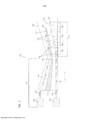
[0015]A figura 1 é uma vista do corte parcial esquemática de uma modalidade de um aparelho para a fabricação de uma manta não tecida.[0015] Figure 1 is a schematic partial section view of a modality of an apparatus for the manufacture of a non-woven blanket.
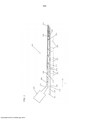
[0016]A figura 2 é uma vista do corte parcial esquemática de outra modali- dade de um aparelho para a fabricação de uma manta não tecida.[0016] Figure 2 is a schematic partial section view of another modality of an apparatus for the manufacture of a non-woven blanket.
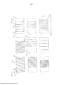
[0017]As figuras 3-8 são vistas superiores de configurações exemplares de uma divisão de mistura.[0017] Figures 3-8 are top views of exemplary configurations of a mixing division.
[0018]A figura 9 é uma vista isométrica de uma divisão de mistura que efetua um gradiente na direção X nos meios.[0018] Figure 9 is an isometric view of a mixing division that effects a gradient in the X direction in the media.
[0019]A figura 10 é uma vista superior da divisão de mistura da figura 9.[0019] Figure 10 is a top view of the mixing division of figure 9.
[0020]A figura 11 é uma vista lateral da divisão de mistura da figura 9.[0020] Figure 11 is a side view of the mixing division of figure 9.
[0021]A figura 12 é uma vista superior de uma divisão de mistura em leque que efetua um gradiente na direção X nos meios.[0021] Figure 12 is a top view of a fan-blending division that effects a gradient in the X direction in the media.
[0022]As figuras 13-15 são vistas superiores de configurações exemplares adicionais de uma divisão de mistura.[0022] Figures 13-15 are top views of additional exemplary configurations of a mixing division.
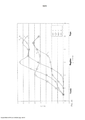
[0023]As figuras 16-19 são gráficos ilustrando o desempenho dos meios com gradiente exemplares.[0023] Figures 16-19 are graphs illustrating the performance of exemplary gradient media.
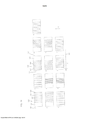
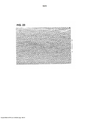
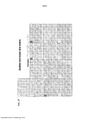
[0024]As figuras 20-23 são imagens de micrografia eletrônica de varredura (SEM) de mantas não tecidas produzidas com configurações diferentes de divisão de mistura.[0024] Figures 20-23 are scanning electron micrograph (SEM) images of non-woven blankets produced with different mix division settings.
[0025]A figura 24 mostra imagens SEM de um corte de uma manta não tecida produzida com uma configuração de divisão de mistura, mostrando regiões diferentes.[0025] Figure 24 shows SEM images of a cut of a non-woven blanket produced with a mixture division configuration, showing different regions.
[0026]A figura 25 é um gráfico do conteúdo de sódio das regiões do meio da figura 24.[0026] Figure 25 is a graph of the sodium content of the middle regions of figure 24.
[0027]A figura 26 é uma vista superior de quatro configurações diferentes de divisão da mistura que foram usadas para gerar os meios relacionados com as figuras 25 e 24.[0027] Figure 26 is a top view of four different mix division configurations that were used to generate the means related to figures 25 and 24.
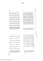
[0028]A figura 27 mostra treze regiões de meios gerados usando uma divisão sólida.[0028] Figure 27 shows thirteen regions of media generated using a solid division.
[0029]A figura 28 mostra treze regiões de meios com gradiente gerados usando uma divisão de mistura com aberturas.[0029] Figure 28 shows thirteen regions of gradient media generated using a blending division with openings.
[0030]A figura 29 é uma comparação de materiais de gradiente feitos com uma divisão de mistura fendida para um meio laminado convencional de duas camadas e para meios de duas camadas feitos com uma divisão sólida é mostrada na tabela 18.[0030] Figure 29 is a comparison of gradient materials made with a split mixture division for a conventional two-layer laminated medium and for two-layer media made with a solid division is shown in table 18.
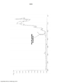
[0031]As figuras 30 e 31 são informação dos espectros do infravermelho de transformação Fourier (FTIR) para meios com gradiente e meios sem gradiente.[0031] Figures 30 and 31 are information on Fourier transformation infrared (FTIR) spectra for gradient media and non-gradient media.
[0032]A figura 32 é imagens de fotomicrografia eletrônica de meios sem gradiente e com gradiente.[0032] Figure 32 is electronic photomicrograph images of media without gradient and with gradient.
[0033]De forma geral, nas figuras 1-32, a dimensão x, a dimensão y e a dimensão z são mostradas, onde relevante.[0033] In general, in figures 1-32, dimension x, dimension y and dimension z are shown, where relevant.
[0034]Uma manta não tecida é descrita aqui, que pode ser usada como um meio de filtro, onde a manta inclui uma primeira fibra e uma segunda fibra, e onde a manta inclui uma região sobre a qual existe uma variação em alguma composição, morfologia da fibra ou propriedade da manta e pode conter uma região sem gradiente constante. Tais regiões podem ser colocadas a montante ou a jusante. A primeira fibra pode ter um diâmetro de pelo menos 1 mícron e uma segunda fibra tendo um diâmetro de no máximo 5 mícrons. A região pode compreender uma porção da espessura e pode ser 10% da espessura ou mais. Em um exemplo, a concentração da segunda fibra varia através da espessura para a manta. Em outro exemplo, uma concentração da segunda fibra varia através da largura ou comprimento da manta. Tal manta pode ter duas ou mais de uma primeira região constante não tecida ou duas ou mais de uma segunda região de gradiente. O meio pode ter uma segunda região da espessura que compreende uma concentração constante da fibra de poli- éster, da fibra separadora e da fibra de eficiência.[0034] A nonwoven blanket is described here, which can be used as a filter medium, where the blanket includes a first fiber and a second fiber, and where the blanket includes a region over which there is variation in some composition, fiber morphology or blanket property and may contain a region without a constant gradient. Such regions can be placed upstream or downstream. The first fiber can have a diameter of at least 1 micron and a second fiber having a diameter of at most 5 microns. The region can comprise a portion of the thickness and can be 10% of the thickness or more. In one example, the concentration of the second fiber varies through the thickness for the blanket. In another example, a concentration of the second fiber varies across the width or length of the mat. Such a blanket may have two or more of a first non-woven constant region or two or more of a second gradient region. The medium may have a second region of thickness which comprises a constant concentration of the polyester fiber, the separator fiber and the efficiency fiber.
[0035]Muitos outros exemplos de variações em uma propriedade da manta serão ainda descritos aqui. Também são descritos aqui um aparelho e um método para a fabricação de tal manta.[0035] Many other examples of variations in a blanket property will still be described here. Also described here are an apparatus and a method for making such a blanket.
[0036]Em uma modalidade, um meio de filtro tendo uma primeira superfície e uma segunda superfície definindo uma espessura, o meio compreendendo pelo menos uma região na espessura, a região compreendendo uma fibra de poliéster, uma fibra separadora tendo um diâmetro de pelo menos 0,3 mícrons e uma fibra de eficiência tendo um diâmetro de no máximo 15 mícrons onde a fibra de poliéster não varia substancialmente em concentração na região e a fibra separadora varia em concentração na região, tal que a concentração dos aumentos da fibra separadora através da região em uma direção de uma superfície para a outra superfície pode ser feita. O meio compreende 30 a 85 % em peso de fibra de poliéster, 2 a 45% em peso de fibra separadora e 10 a 70 % em peso de fibra de eficiência. A fibra de poliés- ter pode compreender uma fibra de bicomponente; a fibra separadora pode compreender uma fibra de vidro; a fibra de eficiência pode compreender uma fibra de vidro. A fibra separadora pode compreender uma fibra de poliéster de fase única.[0036] In one embodiment, a filter medium having a first surface and a second surface defining a thickness, the medium comprising at least one region in the thickness, the region comprising a polyester fiber, a separator fiber having a diameter of at least 0.3 microns and an efficiency fiber having a maximum diameter of 15 microns where the polyester fiber does not vary substantially in concentration in the region and the separator fiber varies in concentration in the region, such that the concentration of the separator fiber increases through the region in one direction from one surface to the other surface can be made. The medium comprises 30 to 85% by weight of polyester fiber, 2 to 45% by weight of separator fiber and 10 to 70% by weight of efficiency fiber. The polyester fiber can comprise a bicomponent fiber; the separating fiber may comprise a glass fiber; the efficiency fiber may comprise a glass fiber. The separator fiber may comprise a single phase polyester fiber.
[0037]Em outra modalidade, um meio de filtro pode ser feito tendo uma primeira borda e uma segunda borda definindo uma largura, cada borda paralela à direção de máquina do meio. O meio compreende uma primeira região compreendendo uma primeira fibra e uma segunda fibra onde a segunda fibra varia em concentração na primeira região, tal que a concentração da segunda fibra aumenta da primeira borda para a segunda borda. A largura do meio de filtro pode compreender uma segunda região da espessura que compreende uma concentração constante da primeira fibra e da segunda fibra. O meio de filtro pode ter uma primeira superfície e uma segunda superfície definindo uma espessura, o meio compreendendo uma segunda região compreendendo um gradiente, a segunda região onde a segunda fibra varia em concentração na segunda região, tal que a concentração da segunda fibra aumenta através da região em uma direção de uma superfície para a outra superfí- cie. No meio de filtro, a segunda região pode atravessar uma porção da espessura do meio. No meio de filtro, a primeira fibra tem uma primeira composição de fibra e a segunda fibra pode ter uma segunda composição de fibra diferente da primeira composição de fibra. No meio de filtro, a primeira fibra pode ser de diâmetro maior do que a segunda fibra. No meio de filtro, a região central da largura pode ser feita onde a concentração da segunda fibra é mais alta na região central. No meio de filtro, o meio de filtro inclui uma primeira região de borda adjacente a primeira borda e uma segunda região de borda adjacente a segunda borda, onde a concentração da segunda fibra é mais alta na primeira região de borda do que na segunda região de borda.[0037] In another embodiment, a filter medium can be made having a first edge and a second edge defining a width, each edge parallel to the machine's middle direction. The medium comprises a first region comprising a first fiber and a second fiber where the second fiber varies in concentration in the first region, such that the concentration of the second fiber increases from the first edge to the second edge. The width of the filter means may comprise a second region of thickness which comprises a constant concentration of the first fiber and the second fiber. The filter medium can have a first surface and a second surface defining a thickness, the medium comprising a second region comprising a gradient, the second region where the second fiber varies in concentration in the second region, such that the concentration of the second fiber increases through from the region in a direction from one surface to the other surface. In the filter medium, the second region can pass through a portion of the thickness of the medium. In the filter medium, the first fiber has a first fiber composition and the second fiber can have a second fiber composition different from the first fiber composition. In the filter medium, the first fiber may be of a larger diameter than the second fiber. In the filter medium, the central region of the width can be made where the concentration of the second fiber is highest in the central region. In the filter medium, the filter medium includes a first edge region adjacent to the first edge and a second edge region adjacent to the second edge, where the concentration of the second fiber is higher in the first edge region than in the second edge region. edge.
[0038]Meios fibrosos tendo variações ou gradientes em composições ou características específicas são úteis em muitos contextos. Uma vantagem substancial da tecnologia dessa revelação é a capacidade de produzir uma ampla faixa de propriedades e desempenho nos meios por via úmida de uma única composição de guarnição ou um pequeno conjunto de guarnições. Uma segunda vantagem, porém importante, é a capacidade de produzir esse amplo espectro de produtos usando um processo de formação de meios por via úmida único. Depois de formado, os meios têm excelentes características de desempenho, mesmo sem o processamento adicional ou camadas adicionadas. Como pode ser observado nos dados abaixo, uma única guarnição pode ser usada para produzir uma faixa de eficiências com longas durações de vida do produtor. Essas propriedades surgem nos materiais com gradiente formados no processo por via úmida da invenção. Eficiência variada implica em um tamanho de poro variado que proporciona vantagens. Por exemplo, os meios com um gradiente de tamanho de poro são vantajosos para, entre outras aplicações, a filtragem de particulados. Os gradientes do tamanho do poro na porção a montante de um filtro podem aumentar a duração de um filtro permitindo que os contaminantes depositem através da profundidade dos meios ao invés de entupir as camadas mais a montante ou a interface. Adicionalmente, os meios fibrosos tendo características de gradiente controláveis e previsíveis, por exemplo, como química da fibra, diâmetro da fibra, reticulação ou fusão ou funcionalidade da união, presença do aglutinante ou gomagem, a presença de particulados e assim por diante são vantajosos em muitas aplicações diversas. Tais gradientes proporcionam desempenho otimizado na remoção e armazenamento dos contaminantes quando utilizado nas aplicações de filtragem. Os gradientes dos materiais e seus atributos associados são vantajosos quando fornecidos através da espessura dos meios fibrosos ou através de outra dimensão, tal como largura ou comprimento cruzado da manta de uma folha de meios fibrosos.[0038] Fibrous media having variations or gradients in specific compositions or characteristics are useful in many contexts. A substantial advantage of the technology of this development is the ability to produce a wide range of properties and performance in wet media from a single trim composition or a small set of trim. A second, but important, advantage is the ability to produce this broad spectrum of products using a unique wet media formation process. Once formed, the media have excellent performance characteristics, even without additional processing or added layers. As can be seen in the data below, a single trim can be used to produce a range of efficiencies with long life spans from the producer. These properties arise in the gradient materials formed in the wet process of the invention. Varied efficiency implies a varied pore size that provides advantages. For example, media with a pore size gradient is advantageous for, among other applications, particulate filtration. Pore size gradients in the upstream portion of a filter can increase the life of a filter by allowing contaminants to deposit through the depth of the media rather than clogging the upstream layers or the interface. In addition, fibrous media having controllable and predictable gradient characteristics, for example, such as fiber chemistry, fiber diameter, crosslinking or fusion or joint functionality, presence of binder or gum, the presence of particulates and so on are advantageous in many diverse applications. Such gradients provide optimum performance in removing and storing contaminants when used in filtration applications. The gradients of the materials and their associated attributes are advantageous when supplied through the thickness of the fibrous media or through another dimension, such as the width or crossed length of the blanket of a sheet of fibrous media.
[0039]Com o uso da tecnologia descrita aqui, estruturas de manta projetadas controladas em um não tecido podem ser fabricadas usando os processos por via úmida, nos quais a manta não tecida tem uma região tendo uma mudança controlada em uma fibra, uma propriedade ou outro aspecto de filtragem em uma direção a partir de uma primeira superfície da manta para uma segunda superfície da manta, ou de uma primeira borda da manta para uma segunda borda de uma manta ou ambos. As mantas projetadas podem ser fabricadas usando técnicas por via úmida com uma ou mais regiões de manta convencionais não tecidas ou tecidas em combinação com uma ou mais regiões de manta(s) não tecida(s) de acordo com as modali-dades descritas aqui tendo a mudança projetada nas propriedades do filtro.[0039] Using the technology described here, projected blanket structures controlled in a nonwoven can be manufactured using wet processes, in which the nonwoven blanket has a region having a controlled change in a fiber, property or another aspect of filtering in one direction from a first mat surface to a second mat surface, or from a first mat edge to a second mat edge or both. The projected blankets can be manufactured using wet techniques with one or more conventional non-woven mat regions or woven in combination with one or more non-woven mat regions (s) according to the modalities described here having the projected change in filter properties.
[0040]A fim de proporcionar contexto para discussão adicional dos meios, método e aparelho, umas poucas modalidades particulares serão brevemente descritas, com a consciência que muitas modalidades adicionais e diferentes serão descritas mais tarde aqui. Em uma modalidade, tal meio pode ser fabricado usando um aparelho que tem uma primeira corrente de fluxo de fluido e uma segunda corrente de fluxo de fluido, cada corrente de fluxo incluindo pelo menos um tipo de fibra. Um exemplo de tal aparelho é mostrado na figura 1. Nesse exemplo particular, o aparelho 100 inclui uma primeira fonte 102 de uma primeira corrente de fluxo 104 e uma segunda fonte 106 de uma segunda corrente de fluxo 108. O aparelho é projetado e configurado para obter a mistura controlada das duas correntes de fluxo usando uma estrutura de divisão de mistura, chamada uma divisão de mistura 110, que define aberturas 112 através dela. A divisão de mistura pode também ser chamada como uma lamela de mistura.[0040] In order to provide context for further discussion of the means, method and apparatus, a few particular modalities will be briefly described, with the awareness that many additional and different modalities will be described later here. In one embodiment, such a medium can be manufactured using an apparatus having a first fluid flow stream and a second fluid flow stream, each flow stream including at least one type of fiber. An example of such an apparatus is shown in figure 1. In this particular example,
[0041]A primeira corrente de fluxo 104 flui para uma região de recepção 114 que é posicionada abaixo da divisão de mistura, enquanto a segunda corrente de fluxo flui para uma superfície superior da divisão de mistura 110. Porções da segunda corrente de fluxo passam através das aberturas 112 para a região de recepção 114, de modo que a mistura ocorre entre a primeira corrente de fluxo 104 e a segunda corrente de fluxo 108. Em uma modalidade onde a primeira corrente de fluxo 104 inclui um primeiro tipo de fibra, e a segunda corrente de fluxo 108 inclui um segundo tipo de fibra, a manta não tecida resultante tem uma distribuição de gradiente do segundo tipo de fibra por toda a espessura da manta, onde a concentração do segundo tipo de fibra diminui a partir de uma superfície inferior para uma superfície superior, usando a orientação da manta na figura 1.[0041] The first flow stream 104 flows into a receiving
[0042]O aparelho da figura 1 pode ser similar a um aparelho do tipo de fabricação de papel em alguns aspectos. Máquinas de fabricar papel na técnica anterior são conhecidas por ter estruturas de divisão que são sólidas e permitem mínima mistura de duas correntes de fluxo. A estrutura de divisão da mistura da invenção é adaptada com aberturas de várias geometrias que cooperam com as pelo menos duas correntes de fluxo para obter um nível desejado e localização da mistura das correntes de fluxo. A divisão de mistura pode ter uma abertura, duas aberturas ou mais aberturas. As formas e as orientações das aberturas da divisão de mistura permitem que uma estrutura de gradiente específica seja atingida na manta, como será discutido em detalhes adicionais aqui.[0042] The apparatus of figure 1 may be similar to a apparatus of the type of papermaking in some aspects. Paper-making machines in the prior art are known to have split structures that are solid and allow minimal mixing of two flow streams. The mixture division structure of the invention is adapted with openings of various geometries that cooperate with at least two flow currents to obtain a desired level and location of the mixture of the flow currents. The mixing room can have one opening, two openings or more openings. The shapes and orientations of the blending division openings allow a specific gradient structure to be achieved in the blanket, as will be discussed in further detail here.
[0043]Em uma modalidade, os meios se referem a meios compostos não tecidos, por via úmida tendo formabilidade, dureza, força de tração, baixa compressibi- lidade e estabilidade mecânica para propriedades de filtragem; alta capacidade de carregamento de particulado, baixa queda de pressão durante o uso e um tamanho de poro e eficiência adequados para uso na filtragem dos fluidos, por exemplo, gases, névoas ou líquidos. Um meio de filtragem de uma modalidade é por via úmida e é composto de formação aleatoriamente orientada de fibra de meios.[0043] In one embodiment, the media refers to non-woven composite media, wetted having formability, hardness, tensile strength, low compressibility and mechanical stability for filtering properties; high particulate loading capacity, low pressure drop during use and a pore size and efficiency suitable for use in filtering fluids, for example, gases, mists or liquids. A filtration medium of a modality is wet and consists of randomly oriented formation of fiber media.
[0044]A manta da fibra que resulta de tal processo usando uma divisão de mistura pode ter uma região sobre a qual existe um gradiente de uma característica da fibra e sobre a qual existe uma mudança na concentração de uma determinada fibra, mas sem ter duas ou mais camadas discretas. Essa região pode ser toda a espessura ou largura do meio ou uma porção da espessura ou largura do meio. A manta pode ter uma região de gradiente, como descrito, e uma região constante tendo mínima mudança na fibra ou características do filtro. A manta de fibra pode ter o gradiente sem as desvantagens do fluxo que estão presentes em outras estruturas que não têm uma interface entre duas ou mais camadas discretas. Em outras estruturas que têm duas ou mais camadas discretas que são unidas, um limite da interface está presente, que pode ser uma camada laminada, um adesivo de laminação ou uma interface de ruptura entre quaisquer duas ou mais camadas. Pelo uso do aparelho de divisão de mistura com aberturas de formação de gradiente em, por exemplo, um processo via úmida, é possível controlar a formação da manta na fabricação dos meios por via úmida e evitar esses tipos de interfaces discretas. Os meios resultantes podem ser relativamente finos enquanto mantendo intensidade mecânica sufici- ente para serem transformados em dobras ou outras estruturas de filtragem.[0044] The fiber mat that results from such a process using a mixing division can have a region over which there is a gradient of a fiber characteristic and over which there is a change in the concentration of a given fiber, but without having two or more discrete layers. This region can be the entire thickness or width of the medium or a portion of the thickness or width of the medium. The blanket can have a gradient region, as described, and a constant region with minimal change in fiber or filter characteristics. The fiber blanket can have the gradient without the flow disadvantages that are present in other structures that do not have an interface between two or more discrete layers. In other structures that have two or more discrete layers that are joined, an interface boundary is present, which can be a laminated layer, a laminating adhesive or a rupture interface between any two or more layers. By using the mixing division apparatus with gradient forming openings in, for example, a wet process, it is possible to control the formation of the blanket in the manufacture of the wet media and avoid these types of discrete interfaces. The resulting media can be relatively thin while maintaining sufficient mechanical intensity to be transformed into folds or other filtering structures.
[0045]Para a finalidade desse pedido de patente, o termo “manta” se refere a uma estrutura semelhante à folha ou planar tendo uma espessura de aproximadamente 0,05 mm até uma espessura indeterminada ou arbitrariamente maior. Essa dimensão da espessura pode ser de 0,5 a 2 cm, 0,8 mm a 1 cm ou 1 mm a 5 mm. Ademais, para a finalidade desse pedido de patente, o termo “manta” se refere a uma estrutura semelhante à folha ou planar tendo uma largura que pode variar de aproximadamente 2,00 cm a uma largura indeterminada ou arbitrária. O comprimento pode ser um comprimento indeterminado ou arbitrário. Tal manta é flexível, usiná- vel, dobrável e de outra forma capaz de transformação em um elemento de filtro ou estrutura de filtro. A manta pode ter uma região com gradiente e pode também ter uma região constante.[0045] For the purpose of this patent application, the term "blanket" refers to a structure similar to the sheet or planar having a thickness of approximately 0.05 mm to an undetermined or arbitrarily greater thickness. This thickness dimension can be 0.5 to 2 cm, 0.8 mm to 1 cm or 1 mm to 5 mm. In addition, for the purpose of this patent application, the term "blanket" refers to a structure similar to the leaf or planar having a width that can vary from approximately 2.00 cm to an indeterminate or arbitrary width. The length can be an indeterminate or arbitrary length. Such a blanket is flexible, machinable, foldable and otherwise capable of being transformed into a filter element or filter structure. The blanket can have a gradient region and can also have a constant region.
[0046]Para a finalidade dessa revelação, o termo “fibra” indica um grande número de fibras relacionadas de modo composicional tal que todas as fibras se situam dentro de uma faixa de tamanhos de fibra ou características de fibra que são distribuídas (tipicamente em uma distribuição substancialmente normal ou Gaussia- na) ao redor de um tamanho ou característica de fibra média ou mediana.[0046] For the purpose of this disclosure, the term "fiber" indicates a large number of fibers compositionally related such that all fibers fall within a range of fiber sizes or fiber characteristics that are distributed (typically in a substantially normal or Gaussian distribution) around a size or characteristic of medium or median fiber.
[0047]Os termos “meios de filtro” ou “meio de filtro”, como esses termos são usados na revelação, se referem a uma camada tendo pelo menos mínima permeabilidade e porosidade, tal que ela é pelo menos minimamente útil como uma estrutura de filtro e não é uma camada substancialmente impermeável, tais como papel convencional, matéria-prima revestida ou papel para impressão fabricado em um processo convencional por via úmida de fabricação de papel.[0047] The terms "filter media" or "filter media", as these terms are used in the development, refer to a layer having at least minimal permeability and porosity, such that it is at least minimally useful as a structure of filter and is not a substantially impermeable layer, such as conventional paper, coated raw material or printing paper manufactured in a conventional wet papermaking process.
[0048]Para a finalidade dessa revelação, o termo “gradiente” indica que alguma propriedade de uma manta varia tipicamente na direção x ou z em pelo menos uma região da manta ou na manta. A variação pode ocorrer a partir de uma primeira superfície para uma segunda superfície ou de uma primeira borda para uma segunda borda da manta. O gradiente pode ser um gradiente de propriedade física ou um gradiente de propriedade química. O meio pode ter um gradiente em pelo menos um do grupo consistindo de permeabilidade, tamanho do poro, diâmetro da fibra, comprimento da fibra, eficiência, solidez, capacidade de umedecimento, resistência química e resistência à temperatura. Em tal gradiente, o tamanho da fibra pode variar, a concentração da fibra pode variar ou qualquer outro aspecto composicional pode variar. Ademais, o gradiente pode indicar que alguma propriedade do filtro do meio, tais como tamanho do poro, permeabilidade, solidez e eficiência pode variar da primeira superfície para a segunda superfície. Outro exemplo de um gradiente é uma mudança na concentração de um tipo particular de fibra de uma primeira superfície para uma segunda superfície, ou de uma primeira borda para uma segunda borda. Gradientes de capacidade de umedecimento, resistência química, intensidade mecânica e resistência à temperatura podem ser obtidos onde a manta tem gradientes de concentrações de fibra de fibras com diferentes químicas de fibra. Tal variação na composição ou propriedade pode ocorrer em uma distribuição de gradiente linear ou distribuição de gradiente não linear. Ou a composição ou o gradiente da concentração da fibra na manta ou meio pode mudar em um modo linear ou não linear em qualquer direção no meio, tal como a montante, a jusante, etc.[0048] For the purpose of this disclosure, the term "gradient" indicates that some property of a blanket typically varies in the x or z direction in at least one region of the blanket or in the blanket. The variation can occur from a first surface to a second surface or from a first edge to a second edge of the mat. The gradient can be a physical property gradient or a chemical property gradient. The medium may have a gradient in at least one of the group consisting of permeability, pore size, fiber diameter, fiber length, efficiency, strength, wetting capacity, chemical resistance and temperature resistance. In such a gradient, the fiber size may vary, the concentration of the fiber may vary, or any other compositional aspect may vary. Furthermore, the gradient may indicate that some properties of the medium filter, such as pore size, permeability, solidity and efficiency, may vary from the first surface to the second surface. Another example of a gradient is a change in the concentration of a particular type of fiber from a first surface to a second surface, or from a first edge to a second edge. Gradients of wetting capacity, chemical resistance, mechanical intensity and temperature resistance can be obtained where the blanket has gradients of fiber concentrations of fibers with different fiber chemistries. Such variation in composition or property can occur in a linear gradient distribution or a non-linear gradient distribution. Either the composition or the gradient of the fiber concentration in the blanket or medium can change in a linear or non-linear way in any direction in the medium, such as upstream, downstream, etc.
[0049]O termo “região” indica uma porção arbitrariamente selecionada da manta com uma espessura menor do que a espessura geral da manta, ou com uma largura menor do que a largura geral da manta. Tal região não é definida por qualquer camada, interface ou outra estrutura, mas é arbitrariamente selecionada somente para comparação com regiões similares da fibra, etc., adjacentes ou próximas à região na manta. Nessa revelação, uma região não é uma camada discreta. Exemplos de tais regiões podem ser observados nas figuras 24, 27 e 28. Na região, a primeira e a segunda fibras podem compreender uma combinação de fibras dife- rentes de modo composicional e a região ser caracterizada por um gradiente que é uma porção da espessura do meio.[0049] The term "region" indicates an arbitrarily selected portion of the blanket with a thickness less than the overall thickness of the blanket, or with a width less than the overall width of the blanket. Such a region is not defined by any layer, interface or other structure, but is arbitrarily selected only for comparison with similar regions of the fiber, etc., adjacent to or close to the region in the blanket. In this revelation, a region is not a discrete layer. Examples of such regions can be seen in figures 24, 27 and 28. In the region, the first and second fibers may comprise a combination of different fibers in a compositional way and the region be characterized by a gradient that is a portion of the thickness the middle one.
[0050]O termo “características da fibra” inclui qualquer aspecto de uma fibra incluindo composição, densidade, tratamento de superfície, a organização dos materiais na fibra, a morfologia da fibra incluindo diâmetro, comprimento, relação de aspectos, grau de plissagem, forma transversal, densidade de volume, distribuição do tamanho ou dispersão do tamanho, etc.[0050] The term "fiber characteristics" includes any aspect of a fiber including composition, density, surface treatment, the organization of materials in the fiber, the morphology of the fiber including diameter, length, aspect ratio, degree of fullness, shape cross section, volume density, size distribution or size dispersion, etc.
[0051]O termo “morfologia da fibra” significa a forma, aparência ou estrutura de uma fibra. Exemplos de morfologias de fibra particulares incluem torcida, plissada, arredondada, semelhante à fita, reta ou espiralada. Por exemplo, uma fibra com uma seção transversal circular tem uma morfologia diferente do que uma fibra com uma forma semelhante à fita.[0051] The term "fiber morphology" means the shape, appearance or structure of a fiber. Examples of particular fiber morphologies include twisted, pleated, rounded, ribbon-like, straight or spiral. For example, a fiber with a circular cross section has a different morphology than a fiber with a ribbon-like shape.
[0052]O termo “tamanho da fibra” é um subconjunto da morfologia e inclui “relação de aspectos”, a relação do comprimento e diâmetro e “diâmetro” se refere ao diâmetro de uma seção transversal circular de uma fibra ou a uma dimensão transversal mais larga de uma seção transversal não circular de uma fibra.[0052] The term "fiber size" is a subset of the morphology and includes "aspect ratio", the relationship of length and diameter and "diameter" refers to the diameter of a circular cross section of a fiber or a transverse dimension width of a non-circular cross section of a fiber.
[0053]Para a finalidade dessa revelação, o termo “divisão de mistura” se refere a uma barreira mecânica que pode separar uma corrente de fluxo de pelo menos uma área de recepção, mas produzir, na divisão, áreas abertas que propiciam um grau controlado de mistura entre a corrente de fluxo e a área de recepção.[0053] For the purpose of this disclosure, the term "mixing division" refers to a mechanical barrier that can separate a flow stream from at least one receiving area, but produce, in the division, open areas that provide a controlled degree of mixing between the flow stream and the receiving area.
[0054]Na divisão de mistura, o termo “fenda” se refere a uma abertura que tem uma primeira dimensão que é significativamente maior do que uma segunda dimensão, tal como um comprimento que é significativamente maior do que uma largura. Para a finalidade dessa revelação, é feito referência a uma “fibra”. É para ser entendido que essa referência se refere a uma fonte de fibra. As fontes de uma fibra são tipicamente produtos de fibra, onde grandes números das fibras têm diâmetro de composição e comprimento ou relação de aspectos similares. Por exemplo, a fibra de bicomponente revelada, fibra de vidro, poliéster e outros tipos de fibra são fornecidos em grande quantidade tendo grandes números de fibras substancialmente similares. Tais fibras são tipicamente dispersas em um líquido, tal como uma fase aquosa, com a finalidade de formação dos meios ou mantas da invenção.[0054] In the mixing division, the term "slit" refers to an opening that has a first dimension that is significantly greater than a second dimension, such as a length that is significantly greater than a width. For the purpose of this disclosure, reference is made to a “fiber”. It is to be understood that this reference refers to a fiber source. The sources of a fiber are typically fiber products, where large numbers of fibers have a composition diameter and length or similar aspect ratio. For example, the disclosed bicomponent fiber, fiberglass, polyester and other types of fiber are supplied in large quantities having large numbers of substantially similar fibers. Such fibers are typically dispersed in a liquid, such as an aqueous phase, for the purpose of forming the means or mats of the invention.
[0055]O termo fibra “de armação” significa, no contexto da invenção, uma fibra em uma concentração substancialmente constante que proporciona intensidade mecânica e estabilidade para o meio. Exemplos de uma fibra de armação são fibra de bicomponente curada ou uma combinação de uma fibra e uma resina em uma camada curada. Em uma modalidade, a fibra de armação compreende uma fibra de bicomponente e ambas a primeira e a segunda fibras compreendem independentemente uma fibra de vidro ou de poliéster. Em outra modalidade, a fibra de armação compreende uma fibra celulósica e a primeira e a segunda fibras compreendem independentemente uma fibra de vidro ou de poliéster.[0055] The term "frame" fiber means, in the context of the invention, a fiber in a substantially constant concentration that provides mechanical intensity and stability for the medium. Examples of a frame fiber are cured two-component fiber or a combination of a fiber and a resin in a cured layer. In one embodiment, the frame fiber comprises a bicomponent fiber and both the first and the second fibers independently comprise a glass or polyester fiber. In another embodiment, the frame fiber comprises a cellulosic fiber and the first and second fibers independently comprise a glass or polyester fiber.
[0056]O termo fibra “separadora” significa, no contexto dos meios da invenção, uma fibra que pode ser dispersa na fibra de armação do meio, onde a fibra separadora pode formar um gradiente e é maior em diâmetro do que a fibra de eficiência.[0056] The term "separator" fiber means, in the context of the means of the invention, a fiber that can be dispersed in the medium frame fiber, where the separator fiber can form a gradient and is larger in diameter than the efficiency fiber .
[0057]O termo fibra “de eficiência”, no contexto da invenção, significa uma fibra que pode formar um gradiente e, em combinação com a fibra de armação ou a fibra separadora, proporciona eficiência do tamanho do poro para o meio. Os meios da invenção, à parte a fibra de armação, a separadora e a de eficiência, podem ter uma de mais fibras adicionais.[0057] The term "efficiency" fiber, in the context of the invention, means a fiber that can form a gradient and, in combination with the frame fiber or the separating fiber, provides pore size efficiency for the medium. The means of the invention, apart from the frame fiber, the separator and the efficiency fiber, can have one of more additional fibers.
[0058]O termo “composição da fibra” significa a natureza química da fibra e o material ou materiais da fibra, incluindo a organização dos materiais da fibra. Tal natureza pode ser orgânica ou inorgânica. As fibras orgânicas são tipicamente polimé- ricas ou biopoliméricas por natureza. A primeira fibra ou a segunda ou a fibra de armação ou separadora pode ser fibra selecionada de uma fibra compreendendo vi dro, celulose, cânhamo, ábaco, uma poliolefina, um poliéster, um poliamido, um polímero halogenado, um poliuretano ou uma combinação desses. Fibras inorgânicas são feitas de vidro, metais e outros materiais de fonte de carbono não orgânicos.[0058] The term "fiber composition" means the chemical nature of the fiber and the material or materials of the fiber, including the organization of the fiber materials. Such a nature can be organic or inorganic. Organic fibers are typically polymeric or biopolymeric in nature. The first fiber or the second or frame or separator fiber may be a fiber selected from a fiber comprising glass, cellulose, hemp, abacus, a polyolefin, a polyester, a polyamide, a halogenated polymer, a polyurethane or a combination thereof. Inorganic fibers are made of glass, metals and other non-organic carbon source materials.
[0059]O termo “meios de profundidade” ou “meios de carregamento de pro-fundidade” se refere aos meios de filtro nos quais um particulado filtrado é adquirido e mantido por toda a espessura ou dimensão z dos meios de profundidade. Embora um pouco do particulado possa, na realidade, acumular na superfície dos meios de profundidade, a qualidade dos meios de profundidade é a capacidade de acumular e reter o particulado dentro da espessura dos meios de profundidade. Tal meio tipicamente compreende uma região com propriedades de filtragem substanciais. Em muitas aplicações, especialmente essas envolvendo taxas de fluxo relativamente altas, meios de profundidade podem ser usados. Meios de profundidade são geralmente definidos em termos da sua porosidade, densidade ou porcentagem de conteúdo de sólidos. Por exemplo, meios de solidez de 2-3% seriam um emaranhado de fibras de meios de profundidade disposto tal que aproximadamente 2-3% do volume geral compreende materiais fibrosos (sólidos), o restante sendo ar ou espaço de gás. Outro parâmetro útil para a definição dos meios de profundidade é o diâmetro da fibra. Se a solidez porcentual é mantida constante, mas o diâmetro da fibra (tamanho) é reduzido, o tamanho do poro é reduzido; isto é, o filtro se torna mais eficiente e capturará mais efetivamente partículas pequenas. Um filtro de meios de profundidade convencional típico é meios de densidade relativamente constante (ou uniforme), isto é, um sistema no qual a solidez dos meios de profundidade permanece substancialmente constante por toda a sua espessura. No meio de profundidade, a segunda fibra pode aumentar de uma primeira superfície a montante para uma segunda superfície a jusante. Tal meio pode compreender uma região de carregamento e uma região de eficiência.[0059] The term "depth means" or "depth loading means" refers to the filter means in which a filtered particulate is acquired and maintained throughout the thickness or z dimension of the depth means. Although some of the particulate may actually accumulate on the surface of the depth means, the quality of the depth means is the ability to accumulate and retain the particulate within the thickness of the depth means. Such a medium typically comprises a region with substantial filtering properties. In many applications, especially those involving relatively high flow rates, depth media can be used. Depth media are generally defined in terms of their porosity, density or percentage of solids content. For example, 2-3% solidity media would be a tangle of fibers of medium depths arranged such that approximately 2-3% of the overall volume comprises fibrous (solid) materials, the remainder being air or gas space. Another useful parameter for defining depth means is the diameter of the fiber. If the percentage strength is kept constant, but the fiber diameter (size) is reduced, the pore size is reduced; that is, the filter becomes more efficient and will capture small particles more effectively. A typical conventional depth media filter is relatively constant (or uniform) density media, that is, a system in which the solidity of the depth media remains substantially constant throughout its thickness. In the depth medium, the second fiber can increase from a first upstream surface to a second downstream surface. Such a medium can comprise a loading region and an efficiency region.
[0060]Por “substancialmente constante” nesse contexto, é planejado que somente flutuações relativamente menores em uma propriedade, tal como concen-tração ou densidade, se alguma, sejam encontradas por toda a profundidade dos meios. Tais flutuações, por exemplo, podem resultar de uma leve compressão de uma superfície engatada externa, por um recipiente no qual os meios de filtro são posicionados. Tais flutuações, por exemplo, podem resultar do enriquecimento ou esvaziamento pequeno, porém inerente, da fibra na manta causado por variações no processo de fabricação. Em geral, a organização dos meios de profundidade pode ser projetada para proporcionar o carregamento dos materiais particulados substan-cialmente através do seu volume ou profundidade. Assim, tais organizações podem ser projetadas para carregar uma maior quantidade de material particulado, em relação aos sistemas de superfície carregada, quando a duração de vida completa do filtro é alcançada. Entretanto, em geral, a troca para tais organizações tem sido eficiência desde que, para o carregamento substancial, relativamente poucos meios sólidos são desejados. Por exemplo, o meio pode ter uma região que é uma região unida uniforme ou substancialmente constante, de fibra de armação, separadora ou de eficiência. A primeira fibra na região unida é uniforme ou substancialmente constante na concentração.[0060] By "substantially constant" in this context, it is planned that only relatively minor fluctuations in a property, such as concentration or density, if any, will be found across the depth of the media. Such fluctuations, for example, can result from a slight compression of an external engaged surface, by a container in which the filter means are positioned. Such fluctuations, for example, may result from the small but inherent enrichment or emptying of the fiber in the blanket caused by variations in the manufacturing process. In general, the organization of the depth means can be designed to provide the loading of particulate materials substantially through their volume or depth. Thus, such organizations can be designed to load a larger amount of particulate material, compared to charged surface systems, when the complete filter life is reached. However, in general, the switch to such organizations has been efficient since, for substantial loading, relatively few solid media are desired. For example, the medium may have a region which is a uniformly or substantially constant, region of frame, separator or efficiency fiber. The first fiber in the joined region is uniform or substantially constant in concentration.
[0061]Para a finalidade dessa revelação, o termo “meios de superfície” ou “meios de carregamento de superfície” se refere a meios de filtro nos quais o particu- lado está em grande parte acumulado na superfície dos meios de filtro e pouco ou nenhum particulado é encontrado dentro da espessura da camada dos meios. Frequentemente o carregamento de superfície é obtido pelo uso de uma camada de fibra fina formada na superfície para agir como uma barreira à penetração do parti- culado na camada do meio.[0061] For the purpose of this disclosure, the term "surface media" or "surface loading media" refers to filter media in which the particulate is largely accumulated on the surface of the filter media and little or no. no particulate is found within the thickness of the media layer. Often surface loading is achieved by using a layer of fine fiber formed on the surface to act as a barrier to the penetration of the particulate into the medium layer.
[0062]Para a finalidade dessa revelação, o termo “tamanho do poro” se refere aos espaços formados por materiais fibrosos dentro dos meios. O tamanho do poro dos meios pode ser estimado pela revisão de fotografias eletrônicas dos meios. O tamanho médio do poro dos meios pode também ser calculado usando um Porô- metro de Fluxo Capilar tendo o modelo no. APP 1200 AEXSC disponível de Porous Materials Inc. de Ithaca, NY.[0062] For the purpose of this disclosure, the term "pore size" refers to spaces formed by fibrous materials within the media. The pore size of the media can be estimated by reviewing electronic photographs of the media. The average pore size of the media can also be calculated using a Capillary Flow Porometer with model no. APP 1200 AEXSC available from Porous Materials Inc. of Ithaca, NY.
[0063]Para a finalidade dessa revelação, o termo “fibra unida” indica que na formação dos meios ou manta da invenção, materiais fibrosos formam uma união com materiais fibrosos adjacentes. Tal união pode ser formada utilizando as propriedades inerentes da fibra, tal como uma camada exterior fusível de uma fibra de bi- componente agindo como um sistema de união. Alternativamente, os materiais fibrosos da manta ou os meios da invenção podem ser unidos usando aglutinantes resinosos separados que são tipicamente fornecidos na forma de uma dispersão aquosa de uma resina do aglutinante. Alternativamente, as fibras da invenção podem também ser reticuladas usando reagentes de reticulação, unidas usando um feixe ele-trônico ou outra radiação energética que pode causar a união de fibra com fibra, através da união em alta temperatura, ou através de qualquer outro processo de união que possa fazer com que as fibras se unam uma fibra na outra.[0063] For the purpose of this disclosure, the term "bonded fiber" indicates that in forming the means or blanket of the invention, fibrous materials form a union with adjacent fibrous materials. Such a joint can be formed using the inherent properties of the fiber, such as a fusible outer layer of a two-component fiber acting as a joint system. Alternatively, the fibrous materials of the mat or the means of the invention can be joined using separate resinous binders which are typically supplied in the form of an aqueous dispersion of a binder resin. Alternatively, the fibers of the invention can also be cross-linked using cross-linking reagents, joined using an electron beam or other energetic radiation that can cause fiber-to-fiber bonding, through high temperature bonding, or through any other bonding process. union that can cause the fibers to join one fiber to the other.
[0064]“Fibra de bicomponente” significa uma fibra formada de um material termoplástico tendo pelo menos uma porção de fibra com um ponto de fusão e uma segunda porção termoplástica com um ponto de fusão menor. A configuração física dessas porções de fibra é tipicamente em uma estrutura lado a lado ou de revestimento-núcleo. Na estrutura lado a lado, as duas resinas são extrusadas tipicamente em uma forma conectada em uma estrutura lado a lado. Uma pessoa poderia também usar fibras lobuladas onde as pontas têm polímero com menor ponto de fusão. A fibra de bicomponente pode ser 30 a 80 % em peso do meio de filtro.[0064] "Two-component fiber" means a fiber formed of a thermoplastic material having at least one portion of fiber with a melting point and a second thermoplastic portion with a lower melting point. The physical configuration of these fiber portions is typically in a tiled or core-clad structure. In the side-by-side structure, the two resins are typically extruded into a shape connected in a side-by-side structure. A person could also use lobulated fibers where the ends have polymer with a lower melting point. The bicomponent fiber can be 30 to 80% by weight of the filter medium.
[0065]Como usado aqui, o termo “fonte” é um ponto de origem, tal como um ponto de origem de uma corrente de fluxo de fluido compreendendo uma fibra. Um exemplo de uma fonte é um bico. Outro exemplo é uma caixa de coleta.[0065] As used here, the term "source" is a point of origin, such as a point of origin of a fluid flow stream comprising a fiber. An example of a fountain is a nozzle. Another example is a collection box.
[0066]Uma “caixa de coleta” é um dispositivo configurado para soltar um flu- xo substancialmente uniforme de guarnição através de uma largura. Em alguns casos, a pressão dentro de uma caixa de coleta é mantida por bombas e controles. Por exemplo, uma caixa de coleta almofadada com ar usa um espaço de ar acima da guarnição como um modo de controle da pressão. Em alguns casos, uma caixa de coleta também inclui rolos retificadores, que são cilindros com grandes furos neles, girando lentamente dentro de uma caixa de coleta almofadada com ar para ajudar a distribuir a guarnição. Em caixas de coleta hidráulicas, a redistribuição da guarnição e a dissolução dos flocos são realizadas com bancos de tubos, áreas de expansão e mudanças da direção do fluxo.[0066] A “collection box” is a device configured to release a substantially uniform flow of trim across a width. In some cases, the pressure inside a collection box is maintained by pumps and controls. For example, an air-cushioned collection box uses an air space above the gasket as a pressure control mode. In some cases, a collection box also includes rectifying rollers, which are cylinders with large holes in them, rotating slowly inside an air-cushioned collection box to help distribute the trim. In hydraulic collection boxes, the redistribution of the lining and the dissolution of the flakes are carried out with tube banks, expansion areas and changes in the direction of flow.
[0067]Uma “guarnição” como esse termo é usado aqui é uma combinação de fibras e líquido. Em uma modalidade, o líquido inclui água. Em uma modalidade, o líquido é água e a guarnição é uma guarnição aquosa.[0067] A "trim" as that term is used here is a combination of fibers and liquid. In one embodiment, the liquid includes water. In one embodiment, the liquid is water and the garnish is an aqueous garnish.
[0068]“Direção de máquina” é a direção que uma manta percorre através de um aparelho, tal como um aparelho que está produzindo a manta. Também, a direção de máquina é a direção da dimensão mais longa de uma manta do material.[0068] "Machine direction" is the direction that a blanket travels through an appliance, such as an appliance that is producing the blanket. Also, the machine direction is the direction of the longest dimension of a material blanket.
[0069]“Direção de manta cruzada” é a direção perpendicular à direção de máquina.[0069] "Cross blanket direction" is the direction perpendicular to the machine direction.
[0070]A “direção x” e a “direção y” definem a largura e o comprimento de uma manta de meios fibrosos, respectivamente e a “direção z” define a espessura ou a profundidade dos meios fibrosos. Como usado aqui, a direção x é idêntica à direção da manta cruzada e a direção y é idêntica à direção de máquina.[0070] The "x direction" and "y direction" define the width and length of a fibrous media blanket, respectively and the "z direction" defines the thickness or depth of the fibrous media. As used here, the x direction is identical to the direction of the cross mat and the y direction is identical to the machine direction.
[0071]Como o termo é usado aqui, “a jusante” é na direção do fluxo de pelo menos uma corrente de fluxo no aparelho que forma a manta. Quando um primeiro componente é descrito como estando a jusante de um segundo componente aqui, isso significa que pelo menos uma porção do primeiro componente está a jusante da totalidade do segundo componente. Porções do primeiro e do segundo componentes podem sobrepor, mesmo embora o primeiro componente esteja a jusante do segun- do componente.[0071] As the term is used here, "downstream" is in the direction of the flow of at least one flow current in the device that forms the blanket. When a first component is described as being downstream of a second component here, it means that at least a portion of the first component is downstream of the entire second component. Portions of the first and second components can overlap, even though the first component is downstream of the second component.
[0072]Um gradiente pode ser gerado em qualquer uma da direção x, direção y ou direção z de uma manta. A estrutura de divisão de mistura particular usada para gerar esses tipos diferentes de gradientes será discutida mais aqui. O gradiente pode também ser gerado em combinações desses planos. O gradiente é efetuado pelo ajuste da distribuição relativa de pelo menos duas fibras. As, pelo menos, duas fibras podem diferir uma da outra por ter uma propriedade física diferente, tais como composição, comprimento, diâmetro, relação de aspectos, morfologia ou combinações desses. Por exemplo, as duas fibras podem diferir no diâmetro tal como para uma primeira fibra de vidro tendo um diâmetro médio de 0,8 mícrons e uma segunda fibra de vidro tendo um diâmetro médio de cinco mícrons.[0072] A gradient can be generated in either the x direction, y direction or z direction of a blanket. The particular blend division structure used to generate these different types of gradients will be discussed further here. The gradient can also be generated in combinations of these planes. The gradient is effected by adjusting the relative distribution of at least two fibers. The at least two fibers may differ from each other in that they have a different physical property, such as composition, length, diameter, aspect ratio, morphology or combinations thereof. For example, the two fibers may differ in diameter as for a first glass fiber having an average diameter of 0.8 microns and a second glass fiber having an average diameter of five microns.
[0073]As pelo menos duas fibras que formam o gradiente podem diferir uma da outra por ter composições químicas diferentes, tratamentos de cobertura ou ambos. Por exemplo, uma primeira fibra poderia ser uma fibra de vidro enquanto uma segunda fibra é uma fibra celulósica.[0073] The at least two fibers that form the gradient can differ from each other in having different chemical compositions, cover treatments or both. For example, a first fiber could be a glass fiber while a second fiber is a cellulosic fiber.
[0074]A manta não tecida descrita aqui pode definir um gradiente de, por exemplo, tamanho do poro, densidade de reticulação, permeabilidade, tamanho médio da fibra, densidade do material, solidez, eficiência, mobilidade líquida, capacidade de umedecimento, química da superfície da fibra, química da fibra ou uma combinação deles. A manta pode também ser fabricada para ter um gradiente em proporções dos materiais incluindo fibras, aglutinantes, resinas, particulados, reticulado- res e assim por diante. Embora pelo menos duas fibras tenham sido descritas até agora, muitas modalidades da invenção incluem três, quatro, cinco, seis ou mais tipos de fibras. É possível que a concentração de um segundo, terceiro e quarto tipos de fibra varie através de uma porção da manta.[0074] The non-woven mat described here can define a gradient of, for example, pore size, crosslink density, permeability, average fiber size, material density, solidity, efficiency, liquid mobility, wetting capacity, chemistry of fiber surface, fiber chemistry or a combination of them. The blanket can also be manufactured to have a gradient in proportions of the materials including fibers, binders, resins, particulates, crosslinkers and so on. Although at least two fibers have been described so far, many embodiments of the invention include three, four, five, six or more types of fibers. It is possible that the concentration of a second, third and fourth fiber type varies across a portion of the blanket.
[0075]O meio das modalidades descritas aqui pode ter uma característica de gradiente. Em um aspecto da invenção, o meio pode ter duas ou mais regiões. A primeira região pode compreender uma porção da espessura do meio com um gradiente definido como definido e discutido acima. A outra região pode compreender outra porção da espessura do meio, tendo um gradiente ou características de meios constantes na ausência substancial de qualquer característica de gradiente importante. Tais meios podem ser formados usando o processo e a máquina da invenção com ajustes de máquina, tal que a camada formada da fibra liberada pela máquina forma tais meios com uma primeira região compreendendo meios constantes e uma segunda região compreendendo meios com gradiente. Os meios podem ser fabricados na ausência substancial de uma estrutura laminada e adesivo ou qualquer interface significativa entre as regiões. Nos meios, existe pelo menos aproximadamente 30 pesos% e no máximo aproximadamente 70 pesos% de uma fibra de bicomponen- te e pelo menos aproximadamente 30 pesos% e no máximo aproximadamente 70 pesos% de uma segunda fibra compreendendo uma fibra de poliéster ou de vidro onde a concentração da segunda fibra é formada em um gradiente contínuo que aumenta da primeira superfície para a segunda superfície. Em grande parte, as fibras da região podem ser similares em qualidade ou podem ser substancialmente diferentes. Por exemplo, a região constante pode compreender uma região de fibra celulósica, fibra de poliéster ou fibra sintética celulósica misturada, enquanto a região com gradiente compreende uma fibra de bicomponente ou fibra de vidro ou outras fibras ou misturas de fibras reveladas em outra parte nessa revelação.[0075] The medium of the modalities described here may have a gradient characteristic. In one aspect of the invention, the medium can have two or more regions. The first region may comprise a portion of the thickness of the medium with a gradient defined as defined and discussed above. The other region may comprise another portion of the medium thickness, having a gradient or characteristics of constant means in the substantial absence of any important gradient characteristics. Such means can be formed using the process and the machine of the invention with machine settings, such that the layer formed from the fiber released by the machine forms such means with a first region comprising constant means and a second region comprising gradient means. The media can be manufactured in the substantial absence of a laminated and adhesive structure or any significant interface between regions. In the media, there is at least approximately 30 pesos% and at most approximately 70 pesos% of a bicomponent fiber and at least approximately 30 pesos% and at most approximately 70 pesos% of a second fiber comprising a polyester or glass fiber where the concentration of the second fiber is formed in a continuous gradient that increases from the first surface to the second surface. To a large extent, the fibers in the region may be similar in quality or may be substantially different. For example, the constant region may comprise a region of cellulosic fiber, polyester fiber or mixed cellulosic synthetic fiber, while the gradient region comprises a bicomponent fiber or glass fiber or other fibers or fiber mixtures disclosed elsewhere in that disclosure. .
[0076]Dependendo dos ajustes da máquina, as regiões são formadas no processo da invenção tipicamente pela formação de uma camada úmida em um fio de formação e depois remoção do líquido que deixa a camada da fibra para secagem adicional e outro processamento. Nos meios secos finais, as regiões podem ter uma variedade de espessuras. Tais meios podem ter uma espessura que varia de aproximadamente 0,3 mm a 5 mm, 0,4 mm a 3 mm, 0,5 mm a 1 mm, pelo menos 0,05 mm ou maior. Tais meios podem ter uma camada da região com gradiente que pode estar em qualquer ponto de aproximadamente 1% a aproximadamente 90% da espessura do meio. Alternativamente, a espessura da camada com gradiente pode compreender de aproximadamente 5% a aproximadamente 95% da espessura dos meios. Ainda outro aspecto do gradiente dos meios da invenção compreende meios onde o gradiente é 10% a 80% da espessura dos meios. Ainda adicionalmente, outra modalidade da invenção compreende meios onde a espessura da camada com gradiente é de aproximadamente 20% a aproximadamente 80% da espessura dos meios em geral. Em modo similar, os meios podem compreender uma região constante onde a região constante é maior do que 1% da espessura dos meios, maior do que 5% da espessura dos meios, maior do que 10% da espessura dos meios ou maior do que 20% da espessura dos meios.[0076] Depending on the settings of the machine, the regions are formed in the process of the invention typically by forming a moist layer on a forming thread and then removing the liquid leaving the fiber layer for further drying and further processing. In the final dry media, the regions can have a variety of thicknesses. Such media can have a thickness ranging from approximately 0.3 mm to 5 mm, 0.4 mm to 3 mm, 0.5 mm to 1 mm, at least 0.05 mm or greater. Such media can have a layer of the region with a gradient that can be anywhere from approximately 1% to approximately 90% of the thickness of the medium. Alternatively, the thickness of the gradient layer can comprise from approximately 5% to approximately 95% of the thickness of the media. Yet another aspect of the gradient of the media of the invention comprises media where the gradient is 10% to 80% of the thickness of the media. Still further, another embodiment of the invention comprises media where the thickness of the gradient layer is from approximately 20% to approximately 80% of the thickness of the media in general. Similarly, the media may comprise a constant region where the constant region is greater than 1% of the media thickness, greater than 5% of the media thickness, greater than 10% of the media thickness or greater than 20 % of media thickness.
[0077]Em uma modalidade, a concentração de uma fibra no fundo da região com gradiente é pelo menos 10% maior do que a concentração dessa fibra no topo da região com gradiente. Em outra modalidade, a concentração de uma fibra no fundo da região com gradiente é pelo menos 15% maior do que a concentração dessa fibra no topo da região com gradiente. Em outra modalidade, a concentração de uma fibra no fundo da região com gradiente é pelo menos 20% maior do que a concentração dessa fibra no topo da região com gradiente.[0077] In one modality, the concentration of a fiber at the bottom of the gradient region is at least 10% higher than the concentration of that fiber at the top of the gradient region. In another modality, the concentration of a fiber at the bottom of the gradient region is at least 15% higher than the concentration of that fiber at the top of the gradient region. In another modality, the concentration of a fiber at the bottom of the gradient region is at least 20% higher than the concentration of that fiber at the top of the gradient region.
[0078]Ter uma região constante e uma região com gradiente nos meios pode servir a várias funções. Em uma modalidade, a camada com gradiente pode agir como uma camada a montante inicial prendendo uma pequena partícula que leva a aumentar a duração de vida para os meios. Ainda outra modalidade da invenção envolve meios onde a região constante é a camada a montante tendo uma característica de filtro projetada para operar eficientemente com um tamanho específico de partícula. Em tal modalidade, a região constante pode então remover quantidades substanciais de um determinado tamanho de partícula dos meios deixando os meios com gradiente para agir como uma reserva removendo outros tamanhos de partícula levando a um aumento da duração de vida do filtro. Como pode ser observado, o uso de uma camada constante e uma região com gradiente pode ser projetado para a finalidade de filtragem de tipos específicos de partícula de uma camada de fluido específica em uma variedade de aplicações diferentes.[0078] Having a constant region and a region with a gradient in the media can serve several functions. In one embodiment, the gradient layer can act as an initial upstream layer by trapping a small particle that leads to longer life for the media. Yet another embodiment of the invention involves media where the constant region is the upstream layer having a filter feature designed to operate efficiently with a specific particle size. In such an embodiment, the constant region can then remove substantial amounts of a given particle size from the media leaving the media with a gradient to act as a buffer by removing other particle sizes leading to an increase in filter life. As can be seen, the use of a constant layer and a gradient region can be designed for the purpose of filtering specific particle types from a specific fluid layer in a variety of different applications.
[0079]As fibras podem ser de uma variedade de composições, diâmetros e relações de aspecto. Os conceitos descritos aqui para formar um gradiente em uma manta não tecida são independentes da matéria-prima da fibra particular usada para criar a manta. Para a identidade composicional da fibra, o versado pode julgar qualquer número de fibras úteis. Tais fibras são normalmente processadas de produtos orgânicos ou inorgânicos. As exigências da aplicação específica para o gradiente podem tornar uma escolha de fibras, ou combinação de fibras, mais adequada. As fibras dos meios com gradiente podem compreender bicomponente, vidro, celulose, cânhamo, ábaco, uma poliolefina, poliéster, um poliamido, um polímero halogenado, poliuretano, acrílico ou uma combinação deles.[0079] The fibers can be of a variety of compositions, diameters and aspect ratios. The concepts described here for forming a gradient in a non-woven blanket are independent of the raw material of the particular fiber used to create the blanket. For the compositional identity of the fiber, the expert can judge any number of useful fibers. Such fibers are usually processed from organic or inorganic products. The specific application requirements for the gradient can make a choice of fibers, or combination of fibers, more appropriate. The fibers of the gradient media may comprise bicomponent, glass, cellulose, hemp, abacus, a polyolefin, polyester, a polyamide, a halogenated polymer, polyurethane, acrylic or a combination thereof.
[0080]Combinações de fibras incluindo combinações de fibras sintéticas e naturais e fibras tratadas e não tratadas, podem ser usadas adequadamente no compósito.[0080] Fiber combinations including combinations of synthetic and natural fibers and treated and untreated fibers, can be used properly in the composite.
[0081]Celulose, fibra celulósica ou fibra de celulose/sintética misturada pode ser um componente básico do meio composto. A fibra celulósica pode ser uma camada separada ou pode ser a fibra de armação ou a fibra separadora e pode ter um diâmetro de pelo menos aproximadamente 20 mícrons e no máximo aproximadamente 30 mícrons. Embora disponíveis de outras fontes, as fibras celulósicas são derivadas primariamente de polpa de madeira. Fibras de polpa de madeira adequa- das para uso da invenção podem ser obtidas de processos químicos bem conhecidos, tais como os processos Kraft e de sulfito, com ou sem branqueamento subsequente. Fibras de polpa podem também ser processadas por métodos termomecâni- cos, quimiotermomecânicos ou combinações deles. A fibra de polpa preferida é produzida por métodos químicos. Fibras de madeira triturada, fibras de polpa de madeira reciclada ou secundária e fibras de polpa de madeira branqueada e não branqueada podem ser usadas. Madeiras moles e madeiras de lei podem ser usadas. Detalhes da seleção das fibras de polpa de madeira são bem conhecidos para aqueles versados na técnica. Essas fibras estão comercialmente disponíveis de várias com-panhias. As fibras de polpa de madeira podem também ser pré-tratadas antes do uso na presente invenção. Esse pré-tratamento pode incluir tratamento físico ou químico, tais como combinação com outros tipos de fibra, sujeição das fibras ao vapor, ou tratamento químico, por exemplo, reticulação das fibras de celulose usando qualquer um de uma variedade de agentes de reticulação. A reticulação aumenta o volume da fibra e a resiliência.[0081] Cellulose, cellulosic fiber or mixed cellulose / synthetic fiber can be a basic component of the composite medium. The cellulosic fiber can be a separate layer or it can be the frame fiber or the separating fiber and can have a diameter of at least approximately 20 microns and at most approximately 30 microns. Although available from other sources, cellulosic fibers are derived primarily from wood pulp. Wood pulp fibers suitable for use of the invention can be obtained from well-known chemical processes, such as the Kraft and sulfite processes, with or without subsequent bleaching. Pulp fibers can also be processed by thermomechanical, chemothermomechanical methods or combinations of them. The preferred pulp fiber is produced by chemical methods. Crushed wood fibers, recycled or secondary wood pulp fibers and bleached and unbleached wood pulp fibers can be used. Soft woods and hardwoods can be used. Details of the selection of wood pulp fibers are well known to those skilled in the art. These fibers are commercially available from several companies. Wood pulp fibers can also be pretreated prior to use in the present invention. Such pretreatment may include physical or chemical treatment, such as combining with other types of fiber, subjecting the fibers to steam, or chemical treatment, for example, crosslinking the cellulose fibers using any of a variety of crosslinking agents. Crosslinking increases fiber volume and resilience.
[0082]Fibras sintéticas incluindo fibras poliméricas, tais como poliolefina, po- liamida, poliéster, cloreto de polivinila, álcool polivinílico (de vários graus de hidrólise), fibras de acetato de polivinila podem também ser usadas no compósito. Fibras sintéticas adequadas incluem, por exemplo, tereftalato de polietileno, polietileno, po- lipropileno, náilon e fibras de raiom. Outras fibras sintéticas adequadas incluem essas feitas de polímeros termoplásticos, celulósicos e outras fibras revestidas com polímeros termoplásticos e fibras de múltiplos componentes, nas quais pelo menos um dos componentes inclui um polímero termoplástico. Fibras de componente único e múltiplo podem ser fabricadas de poliéster, polietileno, polipropileno e outros materiais fibrosos termoplásticos convencionais.[0082] Synthetic fibers including polymeric fibers, such as polyolefin, polyamide, polyester, polyvinyl chloride, polyvinyl alcohol (of varying degrees of hydrolysis), polyvinyl acetate fibers can also be used in the composite. Suitable synthetic fibers include, for example, polyethylene terephthalate, polyethylene, polypropylene, nylon and rayon fibers. Other suitable synthetic fibers include those made of thermoplastic polymers, cellulosic and other fibers coated with thermoplastic polymers and multi-component fibers, in which at least one of the components includes a thermoplastic polymer. Single and multiple component fibers can be manufactured from polyester, polyethylene, polypropylene and other conventional thermoplastic fibrous materials.
[0083]Embora não devam ser interpretados como uma limitação, exemplos de fibras de pré-tratamento incluem a aplicação de tensoativos ou outros líquidos que modificam a química de superfície das fibras. Outros pré-tratamentos incluem a incorporação de antimicrobianos, pigmentos, corantes e meios de adensamento ou amolecimento. Fibras pré-tratadas com outras substâncias químicas, tal como resinas termoplásticas e termorrígidas, também podem ser usadas. Combinações de pré-tratamentos também podem ser utilizadas. Tratamentos similares podem também ser aplicados depois da formação do compósito nos processos de pós- tratamento.[0083] Although they should not be interpreted as a limitation, examples of pretreatment fibers include the application of surfactants or other liquids that modify the surface chemistry of the fibers. Other pretreatments include the incorporation of antimicrobials, pigments, dyes and means of thickening or softening. Fibers pretreated with other chemicals, such as thermoplastic and thermoset resins, can also be used. Pre-treatment combinations can also be used. Similar treatments can also be applied after the formation of the composite in the post-treatment processes.
[0084]Meios de fibra de vidro e meios de fibra de bicomponente que podem ser usados como fibra da manta são revelados na Patente U.S. 7.309.372, emitida em 18 de dezembro de 2007, que é incorporada aqui por referência na sua íntegra. Exemplos adicionais de meios de fibra de vidro e meios de fibra de bicomponente que podem ser usados como fibra da manta são revelados no Pedido de Patente Publicado U.S. 2006/0096932, publicado em 11 de maio de 2006, que é também incorporado aqui por referência na sua íntegra.[0084] Fiberglass media and bicomponent fiber media that can be used as a blanket fiber are disclosed in U.S. Patent 7,309,372, issued December 18, 2007, which is incorporated herein by reference in its entirety. Additional examples of fiberglass media and bicomponent fiber media that can be used as a blanket fiber are disclosed in Published Patent Application US 2006/0096932, published on May 11, 2006, which is also incorporated herein by reference in its full.
[0085]Uma proporção substancial de fibra de vidro pode ser usada na fabricação das mantas descritas aqui. A fibra de vidro pode compreender aproximadamente 30 a 70 % em peso do meio. A fibra de vidro proporciona controle de tamanho do poro e se associa com as outras fibras nos meios para obter meios de taxa de fluxo substancial, alta capacidade, eficiência substancial e alta resistência a úmido. O termo ‘fonte’ de fibra de vidro significa um produto de fibra de vidro de um grande número de fibras de uma composição definida caracterizada por um diâmetro e comprimento médios ou relação de aspectos que fica disponível como um material bruto distinto. Fontes de fibra de vidro adequadas, por exemplo, estão comercialmente disponíveis de Lauscha Fiber International, tendo a localização em Summerville, Carolina do Sul, USA, como B50R tendo um diâmetro de 5 mícrons, B010F tendo um diâmetro de 1 mícron ou B08F tendo um diâmetro de 0,8 mícrons. Fibras similares estão disponíveis de outros fornecedores.[0085] A substantial proportion of fiberglass can be used in the manufacture of the blankets described here. The glass fiber can comprise approximately 30 to 70% by weight of the medium. The glass fiber provides control of pore size and associates with the other fibers in the media to obtain means of substantial flow rate, high capacity, substantial efficiency and high wet strength. The term 'source' of fiberglass means a fiberglass product of a large number of fibers of a defined composition characterized by an average diameter and length or aspect ratio that is available as a separate raw material. Suitable fiberglass sources, for example, are commercially available from Lauscha Fiber International, having the location in Summerville, South Carolina, USA, as B50R having a diameter of 5 microns, B010F having a diameter of 1 micron or B08F having a diameter of 0.8 microns. Similar fibers are available from other suppliers.
[0086]“Fibra de bicomponente” significa uma fibra formada de um material termoplástico tendo pelo menos uma porção de fibra com um ponto de fusão e uma segunda porção termoplástica com um ponto de fusão menor. A configuração física dessas porções de fibra é tipicamente em uma estrutura lado a lado ou de revestimento-núcleo. Na estrutura lado a lado, as duas resinas são tipicamente extrusadas em uma forma conectada em uma estrutura lado a lado. Em uma estrutura de revestimento-núcleo, o material com o menor ponto de fusão forma o revestimento. Também é possível usar, da mesma maneira, fibras onde as pontas têm um polímero de menor ponto de fusão.[0086] "Two-component fiber" means a fiber formed of a thermoplastic material having at least one portion of fiber with a melting point and a second thermoplastic portion with a lower melting point. The physical configuration of these fiber portions is typically in a tiled or core-clad structure. In the side-by-side structure, the two resins are typically extruded in a shape connected in a side-by-side structure. In a core-coating structure, the material with the lowest melting point forms the coating. It is also possible to use, in the same way, fibers where the tips have a polymer with a lower melting point.
[0087]Os polímeros de fibras de bicomponente (revestimento/núcleo ou lado a lado) podem ser compostos de materiais termoplásticos diferentes, tais como, por exemplo, fibras de bicomponente de poliolefina/poliéster (revestimento/núcleo), com o que a poliolefina, por exemplo, revestimento de polietileno, derrete em uma temperatura menor do que o núcleo, por exemplo, poliéster. Polímeros termoplásticos típicos incluem poliolefinas, por exemplo, polietileno, polipropileno, polibutileno e seus copolímeros, e poliésteres tal como tereftalato de polietileno. Um exemplo particular é uma fibra de bicomponente de poliéster conhecida como 271P disponível de DuPont. Outras fibras incluem FIT 201 disponível de Fiber Innovation Technology de Johnson City, Tennessee, Kuraray N720 disponível de Kuraray Co., Ltd. do Japão e Unitika 4080 disponível de Unitika do Japão e materiais similares. Outras fibras in-cluem acetato de polivinila, acetato de cloreto de polivinila, butiral de polivinila, resinas acrílicas, por exemplo, poliacrilato e polimetilacrilato, polimetilmetacrilato, polia- midas, a saber náilon, cloreto de polivinila, cloreto de polivinilideno, poliestireno, álcool polivinílico, poliuretanos, resinas celulósicas, a saber nitrato celulósico, acetato celulósico, butirato de acetato celulósico, etilcelulose, etc., copolímeros de qualquer um dos materiais acima, por exemplo, copolímeros de etileno-acetato de vinilo, co- polímeros de etileno-ácido acrílico, copolímeros de estireno-bloco de butadieno, bor- rachas Kraton e assim por diante. A primeira fibra ou a fibra de armação pode compreender uma fibra de bicomponente compreendendo um núcleo e uma parte externa, cada um independentemente compreendendo um poliéster ou uma poliolefina.[0087] Polymers of bicomponent fibers (coating / core or side-by-side) may be composed of different thermoplastic materials, such as, for example, polyolefin / polyester bicomponent fibers (coating / core), with which the polyolefin , for example, polyethylene coating, melts at a lower temperature than the core, for example, polyester. Typical thermoplastic polymers include polyolefins, for example, polyethylene, polypropylene, polybutylene and their copolymers, and polyesters such as polyethylene terephthalate. A particular example is a two-component polyester fiber known as 271P available from DuPont. Other fibers include FIT 201 available from Fiber Innovation Technology of Johnson City, Tennessee, Kuraray N720 available from Kuraray Co., Ltd. of Japan and Unitika 4080 available from Unitika of Japan and similar materials. Other fibers include polyvinyl acetate, polyvinyl chloride acetate, polyvinyl butyral, acrylic resins, for example, polyacrylate and polymethylacrylate, polymethylmethacrylate, polyamides, namely nylon, polyvinyl chloride, polyvinylene chloride, polyvinylene chloride, polyvinylene chloride, polyvinylene chloride, polyvinylene chloride, polyvinylene chloride, polyvinylene chloride, polyvinylene chloride, polyvinylene chloride, polyvinylene chloride, polyvinylene chloride, polyvinylene chloride, polyvinylene chloride, polyvinylene chloride. polyvinyl, polyurethanes, cellulosic resins, namely cellulosic nitrate, cellulosic acetate, cellulosic acetate butyrate, ethylcellulose, etc., copolymers of any of the above materials, for example, ethylene vinyl acetate copolymers, ethylene-copolymers acrylic acid, styrene-butadiene block copolymers, Kraton rubber and so on. The first fiber or the frame fiber may comprise a bicomponent fiber comprising a core and an outer part, each independently comprising a polyester or a polyolefin.
[0088]Todos esses polímeros demonstram a característica da reticulação do revestimento com a conclusão da primeira fusão. Isso é importante para aplicações com líquido onde a temperatura de aplicação fica tipicamente acima da temperatura de fusão do revestimento.[0088] All of these polymers demonstrate the characteristic of the crosslinking of the coating with the completion of the first melting. This is important for liquid applications where the application temperature is typically above the melting temperature of the coating.
[0089]Meios não tecidos podem conter fibras secundárias feitas de várias fibras hidrófilas, hidrofóbicas, oleófilas e oleofóbicas, igualmente. Essas fibras cooperam com outras fibras para formar um meio de filtragem permeável, mecanicamente estável, porém forte, que pode suportar o esforço mecânico da passagem dos materiais de fluido e pode manter o carregamento do particulado durante o uso. Fibras secundárias são tipicamente fibras de monocomponente com um diâmetro que pode variar de aproximadamente 0,1 a aproximadamente 50 mícrons e podem ser feitas de uma variedade de materiais incluindo algodão de ocorrência natural, linho, lã, várias fibras naturais celulósicas e protéicas, fibras sintéticas incluindo raiom, acrílico, aramida, náilon, poliolefina, fibras de poliéster. Um tipo de fibra secundária é uma fibra de aglutinante que coopera com outros componentes para unir os materiais em uma folha. Outro tipo de fibra secundária é uma fibra estrutural que coopera com outros componentes para aumentar a força de tração e de arrebentamento dos materiais em condições secas e úmidas. Adicionalmente, a fibra do aglutinante pode incluir fibras feitas de tais polímeros como PTFE, cloreto de polivinila, álcool poliviní- lico. Fibras secundárias podem também incluir fibras inorgânicas tais como carbo- no/fibra de grafita, fibra de metal, fibra cerâmica e combinações dessas. Fibras condutoras (por exemplo) fibras de carbono ou fibras de metal incluindo alumínio, aço inoxidável, cobre, etc. podem produzir um gradiente elétrico nos meios. Devido aos desafios ambientais e de fabricação, uma fibra que é química e mecanicamente es- tável durante a fabricação e uso é preferida. Qualquer de tais fibras pode compreender uma combinação de fibras de diâmetros diferentes.[0089] Non-woven media may contain secondary fibers made from various hydrophilic, hydrophobic, oleophilic and oleophobic fibers, as well. These fibers cooperate with other fibers to form a permeable, mechanically stable yet strong filtering medium, which can withstand the mechanical stress of passing fluid materials and can maintain particulate loading during use. Secondary fibers are typically single-component fibers with a diameter that can vary from approximately 0.1 to approximately 50 microns and can be made from a variety of materials including naturally occurring cotton, linen, wool, various natural cellulosic and protein fibers, synthetic fibers including rayon, acrylic, aramid, nylon, polyolefin, polyester fibers. A type of secondary fiber is a binder fiber that cooperates with other components to join materials into a sheet. Another type of secondary fiber is a structural fiber that cooperates with other components to increase the tensile and burst strength of materials in dry and humid conditions. In addition, the binder fiber may include fibers made from such polymers as PTFE, polyvinyl chloride, polyvinyl alcohol. Secondary fibers can also include inorganic fibers such as carbon / graphite fiber, metal fiber, ceramic fiber and combinations thereof. Conductive fibers (for example) carbon fibers or metal fibers including aluminum, stainless steel, copper, etc. can produce an electrical gradient in the media. Due to environmental and manufacturing challenges, a fiber that is chemically and mechanically stable during manufacture and use is preferred. Any of such fibers can comprise a combination of fibers of different diameters.
[0090]Resinas do aglutinante podem ser usadas para ajudar a unir as fibras de armação e outras, tipicamente na ausência da fibra de bicomponente, tais como uma fibra celulósica, de poliéster ou de vidro, em meios mecanicamente estáveis. Tais materiais da resina do aglutinante podem ser usados como um pó seco ou sistema de solvente, mas são tipicamente dispersões aquosas (um látex ou uma de uma série de treliças) de resinas termoplásticas de vinilo. A resina usada como aglutinante pode ser na forma de polímero solúvel ou dispersível em água adicionado diretamente na dispersão de fabricação dos meios ou na forma de fibras do agluti-nante termoplástico do material de resina misturado com as fibras de aramida e vidro a serem ativadas como um aglutinante pelo calor aplicado depois que os meios são formados. Resinas incluem material celulósico, materiais de acetato de vinilo, resinas de cloreto de vinilo, resinas de álcool polivinílico, resinas de acetato de poli- vinila, resinas de acetil de polivinila, resinas acrílicas, resinas metacrílicas, resinas de poliamida, resinas de copolímero de polietileno acetato de vinil, resinas termorrí- gidas tais como fenol de uréia, formaldeído de uréia, melamina, epóxi, poliuretano, resinas de poliéster insaturado curável, resinas poliaromáticas, resinas de resorcinol e resinas de elastômero similares. Os materiais preferidos para o polímero do agluti-nante solúvel ou dispersível em água são resinas termorrígidas solúveis em água ou dispersíveis em água, tais como resinas acrílicas, resinas metacrílicas, resinas de poliamida, resinas de epóxi, resinas fenólicas, poliuréias, poliuretanos, resinas de formaldeído de melamina, resinas de poliésteres e alquídicas, geralmente, e especificamente, resinas acrílicas solúveis em água, resinas metacrílicas, resinas de poli- amida que estão em uso comum na indústria de fabricação dos meios. Tais resinas do aglutinante tipicamente revestem a fibra e aderem fibra com fibra na matriz final não tecida. Resina suficiente pode ser adicionada em uma guarnição para revestir totalmente a fibra sem causar uma película excedente nos poros formados na folha, meios ou material de filtro. A resina pode ser um elastômero, uma resina termorrígi- da, um gel, uma conta, um pélete, um floco, uma partícula ou uma nanoestrutura e pode ser adicionada na guarnição durante a fabricação dos meios ou pode ser aplicada nos meios depois da formação.[0090] Binder resins can be used to help bond frame and other fibers, typically in the absence of two-component fiber, such as cellulosic, polyester or glass fiber, in mechanically stable media. Such binder resin materials can be used as a dry powder or solvent system, but are typically aqueous dispersions (a latex or a series of lattices) of thermoplastic vinyl resins. The resin used as a binder can be in the form of water-soluble or dispersible polymer added directly to the manufacturing dispersion of the media or in the form of fibers from the thermoplastic binder of the resin material mixed with the aramid and glass fibers to be activated as a binder by the heat applied after the media are formed. Resins include cellulosic material, vinyl acetate materials, vinyl chloride resins, polyvinyl alcohol resins, polyvinyl acetate resins, polyvinyl acetyl resins, acrylic resins, methacrylic resins, polyamide resins, copolymer resins from polyethylene vinyl acetate, thermosetting resins such as urea phenol, urea formaldehyde, melamine, epoxy, polyurethane, curable unsaturated polyester resins, polyaromatic resins, resorcinol resins and similar elastomer resins. Preferred materials for the water-soluble or dispersible binder polymer are water-soluble or water-dispersible thermoset resins, such as acrylic resins, methacrylic resins, polyamide resins, epoxy resins, phenolic resins, polyureas, polyurethanes, resins of melamine formaldehyde, polyester and alkyd resins, generally, and specifically, water-soluble acrylic resins, methacrylic resins, polyamide resins that are in common use in the media manufacturing industry. Such binder resins typically coat the fiber and adhere fiber with fiber to the final non-woven matrix. Sufficient resin can be added in a garnish to fully coat the fiber without causing an excess film in the pores formed in the sheet, media or filter material. The resin can be an elastomer, a thermoset resin, a gel, a bead, a pellet, a flake, a particle or a nanostructure and can be added to the garnish during fabrication of the media or can be applied to the media after forming .
[0091]Um aglutinante de látex usado para unir a manta de fibra não tecida tridimensional em cada estrutura não tecida ou usado como o adesivo adicional, pode ser selecionado de vários adesivos de látex conhecidos na técnica. O versado pode selecionar o adesivo de látex particular dependendo do tipo das fibras celulósicas que devem ser unidas. O adesivo de látex pode ser aplicado por técnicas conhecidas tais como pulverização ou formação de bolhas. De forma geral, adesivos de látex inicialmente tendo de 15 a 25% de sólidos são usados. A dispersão pode ser feita pela dispersão das fibras e depois adição do material do aglutinante ou dispersão do material do aglutinante e depois adição das fibras. A dispersão pode também ser feita pela combinação de uma dispersão de fibras com uma dispersão do material do aglutinante. A concentração das fibras totais na dispersão pode variar de 0,01 a 5 ou 0,005 a 2 % em peso com base no peso total da dispersão. A concentração do material do aglutinante na dispersão pode variar de 10 a 50 % em peso com base no peso total das fibras. Gomagem, enchimentos, cores, auxiliares de retenção, fibras recicladas de fontes alternativas, aglutinantes, adesivos, reticuladores, partículas, agentes antimicrobianos, fibras, resinas, partículas, materiais orgânicos ou inorgânicos com molécula pequena ou qualquer mistura desses pode ser incluída na dispersão.[0091] A latex binder used to join the three-dimensional non-woven fiber mat in each non-woven structure or used as the additional adhesive, can be selected from several latex adhesives known in the art. The skilled person can select the particular latex adhesive depending on the type of cellulosic fibers to be bonded. The latex adhesive can be applied by known techniques such as spraying or blistering. In general, latex adhesives initially having 15 to 25% solids are used. The dispersion can be done by dispersing the fibers and then adding the binder material or dispersing the binder material and then adding the fibers. The dispersion can also be made by combining a fiber dispersion with a dispersion of the binder material. The concentration of total fibers in the dispersion can vary from 0.01 to 5 or 0.005 to 2% by weight based on the total weight of the dispersion. The concentration of the binder material in the dispersion can vary from 10 to 50% by weight based on the total weight of the fibers. Gum, fillers, colors, retention aids, recycled fibers from alternative sources, binders, adhesives, crosslinkers, particles, antimicrobial agents, fibers, resins, particles, organic or inorganic materials with small molecule or any mixture of these can be included in the dispersion.
[0092]Uma cobertura ou elemento para a união seletiva se refere a uma metade que une seletivamente um material parceiro. Tais coberturas ou elementos são úteis para prender ou capturar seletivamente um material parceiro alvo em uma fibra.[0092] A cover or element for the selective union refers to a half that selectively joins a partner material. Such covers or elements are useful for selectively attaching or capturing a target partner material to a fiber.
[0093]Exemplos de metades úteis como tal cobertura ou elemento incluem espécies moleculares bioquímicas, químicas inorgânicas ou químicas orgânicas e podem ser derivadas por métodos naturais, sintéticos ou recombinantes. Tais metades incluem, por exemplo, absorventes, adsorventes, polímeros, celulósicos e ma- cromoléculas, tais como polipeptídeos, ácidos nucléicos, carboidrato e lipídeo. Tal cobertura pode também compreender uma cobertura química reativa que pode reagir com componentes, solúvel ou insolúvel em uma corrente de fluido durante o processamento do filtro. Tais coberturas podem compreender ambos os materiais de cobertura polimérica e de pequena molécula ou grande molécula. Tal cobertura pode ser depositada sobre ou aderida aos componentes de fibra a fim de realizar reações químicas na superfície da fibra.[0093] Examples of halves useful as such a cover or element include biochemical, inorganic or organic chemical molecular species and can be derived by natural, synthetic or recombinant methods. Such halves include, for example, absorbents, adsorbents, polymers, cellulosics and macromolecules, such as polypeptides, nucleic acids, carbohydrates and lipids. Such a coating may also comprise a reactive chemical coating that can react with components, either soluble or insoluble in a fluid stream during filter processing. Such covers may comprise both polymeric and small molecule or large molecule cover materials. Such a covering can be deposited on or adhered to the fiber components in order to carry out chemical reactions on the fiber surface.
[0094]Outras tais coberturas ou elementos que podem ser presos em uma fibra e que exibem a união seletiva em um material parceiro alvo são conhecidos na técnica e podem ser utilizados no dispositivo, aparelho ou métodos da invenção dados os ensinamentos e a orientação providos aqui.[0094] Other such covers or elements which can be attached to a fiber and which exhibit selective bonding to a target partner material are known in the art and can be used in the device, apparatus or methods of the invention given the teachings and guidance provided here .
[0095]Um particulado quimicamente reativo pode ser disperso nos meio das modalidades descritas aqui.[0095] A chemically reactive particulate can be dispersed among the modalities described here.
[0096]O particulado da invenção pode ser feito de ambos materiais orgânicos e inorgânicos e híbridos. Os particulares podem incluir partículas de carbono, tais como carbono ativado, resinas de troca iônica/contas, partículas de zeólito, terra diatomácea, partículas de alumina, tal como alumina ativada, partículas poliméricas incluindo, por exemplo, monômero de estireno e partículas absorventes, tal como partículas superabsorventes comercialmente disponíveis. Particulados orgânicos podem ser feitos de copolímeros de poliestireno ou estireno expandidos ou de outra forma, náilon ou copolímeros de náilon, polímeros de poliolefina incluindo polietileno, polipropileno, etileno, copolímeros de olefina, copolímeros de propileno olefina, polímeros e copolímeros acrílicos incluindo polimetilmetacrilato e poliacrilonitrilo. Ademais, o particulado pode compreender materiais celulósicos e contas derivadas de celulose. Tais contas podem ser fabricadas a partir de celulose ou de derivados de celulose, tais como metilcelulose, etilcelulose, hidroximetiletilcelulose, hidroxietilcelu- lose e outros. Ademais, os particulados podem compreender uma terra diatomácea, zeólito, talco, argila, silicato, bióxido de silício fundido, contas de vidro, contas cerâmicas, particulados de metal, óxidos de metal, etc. O particulado da invenção pode também compreender um absorvente reativo ou estrutura semelhante à fibra adsor- vente tendo um comprimento e diâmetro predeterminados. Outros exemplos de aditivos são partículas tendo uma cobertura reativa.[0096] The particulate of the invention can be made of both organic and inorganic and hybrid materials. Particulars may include carbon particles, such as activated carbon, ion exchange resins / beads, zeolite particles, diatomaceous earth, alumina particles, such as activated alumina, polymeric particles including, for example, styrene monomer and absorbent particles, such as commercially available superabsorbent particles. Organic particulates can be made of expanded polystyrene or styrene copolymers or otherwise, nylon or nylon copolymers, polyolefin polymers including polyethylene, polypropylene, ethylene, olefin copolymers, propylene olefin copolymers, polymers and acrylic polymers and acrylic copolymers. . In addition, the particulate may comprise cellulosic materials and beads derived from cellulose. Such beads can be manufactured from cellulose or cellulose derivatives, such as methylcellulose, ethylcellulose, hydroxymethylethylcellulose, hydroxyethylcellulose and others. In addition, the particulates may comprise a diatomaceous earth, zeolite, talc, clay, silicate, fused silicon dioxide, glass beads, ceramic beads, metal particles, metal oxides, etc. The particulate of the invention may also comprise a reactive absorbent or adsorbent fiber-like structure having a predetermined length and diameter. Other examples of additives are particles having a reactive coating.
[0097]As partículas podem ficar em camadas diferentes dentro do emaranhado fibroso. Particulados, fibras, resinas ou qualquer mistura desses que ajudam nas propriedades finais dos meios de gradiente podem ser adicionados na dispersão em qualquer momento durante o processo de fabricação ou acabamento dos meios com gradiente.[0097] The particles can be in different layers within the fibrous tangle. Particulates, fibers, resins or any mixture of these that aid in the final properties of the gradient media can be added to the dispersion at any time during the manufacturing or finishing process of the gradient media.
[0098]Aditivos de gomagem, enchimentos, cores, auxiliares de retenção, fibras recicladas de fontes alternativas, aglutinantes, adesivos, reticuladores, partículas ou agentes anti-microbianos podem ser adicionados na dispersão aquosa.[0098] Gum additives, fillers, colors, retention aids, recycled fibers from alternative sources, binders, adhesives, crosslinkers, particles or anti-microbial agents can be added to the aqueous dispersion.
[0099]Na técnica anterior, certas estruturas foram fabricadas pela formação de uma primeira camada separadamente de uma segunda camada e depois combinando as camadas, resultando em uma mudança gradual nas características dos meios através da espessura dos meios resultantes. Tal combinação envolve tipicamente a formação de uma interface entre as camadas. Tal interface inclui algumas vezes uma zona entre as camadas caracterizada por fibra esmagada, tal que as fibras não estão mais no mesmo estado físico como as folhas laminadas separadas como as folhas antes da laminação. Outras interfaces contêm um adesivo unindo as camadas. Em muitas das modalidades da manta não tecida descrita aqui, tais efeitos da interface incluindo a interface da camada esmagada e a interface da camada adesiva estão ausentes da manta não tecida.[0099] In the prior art, certain structures were manufactured by forming a first layer separately from a second layer and then combining the layers, resulting in a gradual change in the characteristics of the media through the thickness of the resulting media. Such a combination typically involves the formation of an interface between the layers. Such an interface sometimes includes a zone between the layers characterized by crushed fiber, such that the fibers are no longer in the same physical state as the laminated sheets separated as the sheets before lamination. Other interfaces contain an adhesive joining the layers. In many of the modalities of the nonwoven web described here, such interface effects including the interface of the crushed layer and the interface of the adhesive layer are absent from the nonwoven web.
[00100]Uma modalidade dos meios descritos aqui é caracterizada pela ausência de qualquer limite ou barreira, tal como na direção x, direção y e direção z dentro de uma manta fibrosa.[00100] A modality of the means described here is characterized by the absence of any limit or barrier, such as in the x direction, y direction and z direction within a fibrous blanket.
[00101] Uma vantagem substancial da tecnologia da invenção é obter uma formação de meios com uma faixa de propriedades úteis usando uma ou um conjunto limitado de guarnições e um processo por via úmida de etapa única.[00101] A substantial advantage of the technology of the invention is to obtain media formation with a range of useful properties using one or a limited set of linings and a single step wet process.
[00102]Em uma modalidade, essa invenção utiliza um processo por via úmida de passagem única para gerar um gradiente dentro das dimensões de um emaranhado fibroso. Por uma passagem única, é planejado que a mistura das fibras na região e o depósito da guarnição ou guarnições misturadas ocorram somente uma vez durante uma passagem da produção para produzir os meios com gradiente. Nenhum processamento adicional é feito para acentuar o gradiente. O processo de passagem única usando o aparelho da divisão de mistura proporciona meios com gradiente sem uma interface discernível ou detectável dentro dos meios. O gradiente dentro dos meios pode ser definido do topo para a base ou através da espessura dos meios. Alternativamente o, além disso, um gradiente dentro dos meios pode ser definido através de uma dimensão de comprimento ou largura dos meios.[00102] In one embodiment, this invention uses a single-pass wet process to generate a gradient within the dimensions of a fibrous tangle. Through a single pass, it is planned that the mixing of the fibers in the region and the deposit of the mixed garnish or garnishes occur only once during a production pass to produce the gradient media. No further processing is done to accentuate the gradient. The single pass process using the mixing division apparatus provides gradient media without a discernible or detectable interface within the media. The gradient within the media can be defined from the top to the bottom or through the thickness of the media. Alternatively, in addition, a gradient within the means can be defined through a dimension of length or width of the means.
[00103]Em uma modalidade, um método de fabricação de uma manta não tecida inclui distribuir uma primeira corrente de fluido de uma primeira fonte, onde a corrente de fluido inclui a fibra. Um aparelho usado nesse método tem uma divisão de mistura a jusante da primeira fonte e a divisão de mistura é posicionada entre duas trajetórias de fluxo da primeira fonte. As trajetórias de fluxo são separadas pela divisão de mistura, que define uma ou mais aberturas na divisão de mistura que permitem a comunicação de fluido de pelo menos uma trajetória de fluxo para a outra. O método ainda inclui coletar a fibra em uma região de recepção situada próxima e a jusante da fonte. A região de recepção é projetada para receber a corrente de fluxo distribuída da fonte e formar uma camada úmida pela coleta da fibra. Uma etapa adicional do método é secar a camada úmida para formar a manta não tecida.[00103] In one embodiment, a method of fabricating a non-woven blanket includes distributing a first fluid stream from a first source, where the fluid stream includes the fiber. An apparatus used in this method has a mixing division downstream of the first source and the mixing division is positioned between two flow paths of the first source. The flow paths are separated by the mixing division, which defines one or more openings in the mixing division that allow fluid communication from at least one flow path to the other. The method also includes collecting the fiber in a reception region located near and downstream from the source. The receiving region is designed to receive the distributed flow current from the source and form a moist layer by collecting the fiber. An additional step in the method is to dry the wet layer to form the non-woven blanket.
[00104]Em outra modalidade, um método de fabricação de uma manta não tecida inclui fornecer uma guarnição de uma fonte, a guarnição incluindo pelo menos uma primeira fibra e distribuir uma corrente da guarnição de um aparelho para fabricar uma manta não tecida. O aparelho tem uma divisão de mistura a jusante de uma fonte da corrente e a divisão de mistura define pelo menos uma abertura para permitir a passagem de pelo menos uma porção da corrente. O método ainda inclui coletar a fibra passando através da abertura em uma região de recepção situada a jusante da fonte, coletar o restante da fibra na região de recepção em uma porção a jusante da divisão de mistura e secar a camada úmida para formar a manta não tecida.[00104] In another embodiment, a method of fabricating a non-woven blanket includes providing a garnish from a source, the garment including at least a first fiber, and distributing a garnish chain from an apparatus to manufacture a non-woven blanket. The apparatus has a mixing division downstream of a current source and the mixing division defines at least one opening to allow at least a portion of the current to pass through. The method also includes collecting the fiber passing through the opening in a receiving region located downstream from the source, collecting the rest of the fiber in the receiving region in a portion downstream of the mixing division and drying the wet layer to form the non-woven blanket. woven.
[00105]Em uma modalidade, a divisão de mistura é usada no contexto de uma máquina de papel modificada, tal como uma máquina de fabricar papel inclinada ou outras máquinas que serão ainda discutidas aqui. A divisão de mistura pode ser posicionada em um plano horizontal ou em uma inclinação descendente ou ascendente. Guarnições deixando as fontes na máquina prosseguem para uma zona de formação ou região de recepção. As guarnições são pelo menos inicialmente separadas pela divisão de mistura. A divisão de mistura da invenção tem fendas ou aberturas na sua superfície.[00105] In one embodiment, the mixing division is used in the context of a modified paper machine, such as an inclined paper making machine or other machines that will be discussed further here. The mixing division can be positioned on a horizontal plane or on a downward or upward slope. Fittings leaving the fountains on the machine proceed to a training area or reception region. The linings are at least initially separated by the mixing division. The mixing room of the invention has cracks or openings in its surface.
[00106]Os meios com gradiente que são formados usando o aparelho da divisão de mistura da invenção são o resultado da mistura regional e controlada das guarnições fornecidas das fontes na transição. Existem muitas opções diferentes para o projeto da divisão de mistura. Por exemplo, aberturas maiores ou mais frequentes no início da divisão da mistura resultarão em mais mistura quando as guarnições retêm a maior parte da água. Aberturas maiores ou mais frequentes no fim da divisão da mistura resultarão na mistura depois que mais líquido foi removido. Dependendo dos materiais presentes nas guarnições e das propriedades finais desejadas, mais mistura nos estágios precoces do processo de formação do meio ou mais mistura de fibras posteriormente no processo de formação do meio pode proporcionar vantagens na construção final dos meios fibrosos com gradiente.[00106] The gradient media that are formed using the mixing division apparatus of the invention are the result of regional and controlled mixing of the linings provided from the sources in the transition. There are many different options for the design of the mixing division. For example, larger or more frequent openings at the beginning of the division of the mixture will result in more mixing when the linings retain most of the water. Larger or more frequent openings at the end of the division of the mixture will result in mixing after more liquid has been removed. Depending on the materials present in the linings and the desired final properties, more mixing in the early stages of the medium forming process or more mixing of fibers later in the medium forming process can provide advantages in the final construction of the gradient fibrous media.
[00107]Quando mais do que duas guarnições são utilizadas usando o aparelho e métodos da invenção, então três ou mais gradientes de fibra podem ser formados. Ademais, uma ou mais do que uma divisão de mistura pode ser utilizada. Será verificado que a mistura pode ser variada através da manta durante a formação do meio selecionando um padrão de aberturas na divisão de mistura que varia através da manta. Será verificado que a máquina e a divisão de mistura da invenção oferecem essa variabilidade e controle com facilidade e eficiência. Será verificado que meios com gradiente serão formados em uma passagem ou aplicação sobre a divisão de mistura. Será verificado que materiais com gradiente, por exemplo, meios fibrosos não tendo interfaces discretas discerníveis, mas tendo propriedades químicas ou físicas controláveis, podem ser formados usando o aparelho e métodos da invenção. Será verificado que a concentração ou razão de, por exemplo, tamanhos variáveis de fibra, proporciona uma densidade crescente ou decrescente dos poros por todos os meios com gradiente específico. Os meios fibrosos assim formados podem ser utilizados vantajosamente em uma ampla variedade de aplicações.[00107] When more than two linings are used using the apparatus and methods of the invention, then three or more fiber gradients can be formed. In addition, one or more than one mixing division can be used. It will be seen that the mixture can be varied through the blanket during the formation of the medium by selecting a pattern of openings in the mixture division that varies across the blanket. It will be found that the machine and the mixing division of the invention offer this variability and control with ease and efficiency. It will be verified that gradient media will be formed in a passage or application over the mixing division. It will be seen that gradient materials, for example, fibrous media not having discernible discrete interfaces, but having controllable chemical or physical properties, can be formed using the apparatus and methods of the invention. It will be seen that the concentration or ratio of, for example, variable fiber sizes, provides an increasing or decreasing density of the pores by all means with specific gradient. The fibrous media thus formed can be used advantageously in a wide variety of applications.
[00108]Em uma modalidade, a divisão de mistura é utilizada em um aparelho para fabricar uma manta não tecida, onde o aparelho inclui uma ou mais fontes configuradas para distribuir uma primeira corrente de fluxo de fluido incluindo uma fibra e uma segunda corrente de fluxo de fluido também incluindo uma fibra. A divisão de mistura é posicionada a jusante da uma ou mais fontes e entre a primeira e a segunda correntes de fluxo. A divisão de mistura define uma ou mais aberturas que permitem a comunicação de fluido entre as duas correntes de fluxo. O aparelho também inclui uma região de recepção situada a jusante da uma ou mais fontes e projetada para receber pelo menos uma corrente de fluxo combinada e formar uma manta não tecida pela coleta da fibra da corrente de fluxo combinada.[00108] In one embodiment, the mixing division is used in an apparatus to manufacture a non-woven mat, where the apparatus includes one or more sources configured to distribute a first flow stream of fluid including a fiber and a second flow stream of fluid also including a fiber. The mixing division is positioned downstream from one or more sources and between the first and second flow streams. The mixing division defines one or more openings that allow fluid communication between the two flow streams. The apparatus also includes a receiving region located downstream of one or more sources and designed to receive at least one combined flow stream and form a non-woven blanket by collecting the fiber from the combined flow stream.
[00109]Em outra modalidade, a divisão de mistura é incluída em um aparelho que inclui uma primeira fonte configurada para distribuir uma primeira corrente de fluxo de fluido incluindo uma fibra e uma segunda fonte configurada para distribuir uma segunda corrente de fluxo de fluido também incluindo uma fibra. A divisão de mistura é a jusante da primeira e da segunda fontes, é posicionada entre a primeira e a segunda correntes de fluxo e define duas ou mais aberturas na divisão de mistura que permitem a comunicação de fluido e a mistura entre a primeira e a segunda correntes de fluxo. O aparelho também inclui uma região de recepção situada a jusante da primeira e da segunda fontes e projetada para receber pelo menos uma corrente de fluxo combinada e formar uma manta não tecida pela coleta da corrente de fluxo combinada.[00109] In another embodiment, the mixing division is included in an apparatus that includes a first source configured to distribute a first fluid flow stream including a fiber and a second source configured to distribute a second fluid flow stream also including a fiber. The mixing division is downstream of the first and second sources, is positioned between the first and second flow streams and defines two or more openings in the mixing division that allow fluid communication and mixing between the first and second flow currents. The apparatus also includes a receiving region located downstream of the first and second sources and designed to receive at least one combined flow stream and form a non-woven blanket by collecting the combined flow stream.
[00110]Em ainda outra modalidade, um aparelho para fabricar uma manta não tecida inclui uma fonte projetada para distribuir uma primeira corrente de fluxo líquido incluindo uma fibra, uma divisão de mistura a jusante da fonte, a divisão de mistura compreendendo uma ou mais aberturas na divisão de mistura e uma região de recepção situada a jusante da fonte e projetada para receber a corrente de fluxo e formar uma manta não tecida pela coleta da fibra da corrente de fluxo.Modalidades específicas adicionais serão descritas aqui.[00110] In yet another embodiment, an apparatus for manufacturing a non-woven blanket includes a source designed to distribute a first stream of liquid flow including a fiber, a mixing division downstream of the source, the mixing division comprising one or more openings in the mixing division and a receiving region located downstream from the source and designed to receive the flow current and form a non-woven blanket by collecting the fiber from the flow current. Additional specific modalities will be described here.
[00111]Como previamente discutido, a figura 1 mostra um corte esquemático através de um aparelho ou máquina de fabricar papel inclinada modificada 100 com duas fontes 102, 106 e uma divisão de mistura 110. Uma modalidade de aparelho diferente será discutida com relação à figura 2, que é um esquemático de uma máquina de fabricar papel inclinada modificada 200 com uma fonte.[00111] As previously discussed, figure 1 shows a schematic cut through a modified inclined paper apparatus or
[00112]As fontes 102, 106 podem ser configuradas como caixas de coleta. Uma caixa de coleta é um dispositivo configurado para soltar um fluxo substancialmente uniforme de guarnição através de uma largura.[00112] The sources 102, 106 can be configured as collection boxes. A collection box is a device configured to release a substantially uniform flow of trim across a width.
[00113]A divisão de mistura pode ser projetada para se estender por uma seção de escoamento inteira da máquina e se conectar em trilhos laterais da máquina. A divisão de mistura pode se estender através de toda a largura da região de recepção.[00113] The mixing division can be designed to extend over an entire flow section of the machine and connect to the machine's side rails. The mixing division can extend across the entire width of the receiving region.
[00114]A máquina de fabricar papel inclinada da figura 1 inclui dois tubos de alimentação 115, 116 que transportam as correntes de fluxo 104, 108 para longe das fontes 102, 106. A figura 1 mostra duas fontes posicionadas uma em cima da outra. Entretanto, o aparelho 100 pode incluir uma, duas, três ou mais fontes empilhadas, fontes alimentando em outras fontes, fontes escalonadas na direção de máquina na extremidade distal da divisão de mistura e fontes escalonadas na direção cruzada da manta na extremidade distal da divisão de mistura. No caso de uma disposição de fonte única, uma fonte pode conter divisões internas onde as guarnições podem ser segregadas a fim de produzir duas correntes de fluxo.[00114] The inclined paper making machine of figure 1 includes two
[00115]Os tubos de alimentação 115, 116 podem ser inclinados um pouco para ajudar no movimento das correntes de fluxo. Na modalidade da figura 1, os tubos de alimentação 115, 116 são inclinados para baixo. A divisão de mistura 110 está presente na extremidade distal do tubo de alimentação superior 116. A divisão de mistura pode ser inclinada para baixo ou para cima dependendo dos meios com gradiente sendo produzidos. A divisão de mistura 110 define aberturas 112, que serão ainda descritas aqui. A divisão de mistura tem uma extremidade proximal 122 mais próxima das fontes e uma extremidade distal 124 distante das fontes.[00115] The
[00116]Na modalidade da figura 1, as aberturas 112 são definidas na porção da divisão de mistura 110 que fica acima do guia de fio 118. Entretanto, em outras modalidades, a divisão de mistura define aberturas em uma porção mais a montante do aparelho, tal como entre as duas correntes de fluxo 115, 116.[00116] In the embodiment of figure 1, the
[00117]Em uma extremidade distal do tubo de alimentação inferior 115, a primeira corrente de fluxo 104 é transportada em um guia de fio 118 que é enrolado nos roletes (não mostrados) que são conhecidos na técnica. No guia de fio, a guarnição da primeira corrente de fluxo 104 se move para a região de recepção 114. Um pouco da guarnição da segunda corrente de fluxo 108 desce através das aberturas 112 como permitido pelas dimensões das aberturas 112, para a região de recepção 114. Como resultado, a segunda corrente de fluxo 108 mistura e combina com a primeira corrente de fluxo 104 na região de recepção 114.[00117] At a distal end of the lower feed tube 115, the first flow chain 104 is carried on a wire guide 118 which is wound on the rollers (not shown) which are known in the art. In the wire guide, the gasket of the first flow stream 104 moves to the receiving
[00118]As dimensões e as posições das aberturas da divisão de mistura 112 terão um grande efeito na ajustagem e nível de mistura da primeira e da segunda correntes de fluxo. Em uma modalidade, uma primeira porção da segunda corrente de fluxo 108 passará através de uma primeira abertura, e uma segunda porção da segunda corrente de fluxo passará através da segunda abertura e uma terceira porção da segunda corrente de fluxo passará através da terceira abertura e assim por diante, com qualquer porção restante da segunda corrente de fluxo passando sobre a extremidade distal 124 da divisão de mistura e para a região de recepção 114.[00118] The dimensions and positions of the opening of the
[00119]A primeira e a segunda guarnições que são suficientemente diluídas facilitam a mistura das fibras das duas correntes de fluxo na porção de mistura da região de recepção. Na guarnição, a fibra é dispersa no fluido, tal como água, e adi- tivos. Em uma modalidade, uma ou ambas das guarnições é uma guarnição aquosa. Em uma modalidade a porcentagem de peso (peso%) da fibra em uma guarnição pode ficar na faixa de aproximadamente 0,01 a 1 peso%. Em uma modalidade o percentual em peso da fibra em uma guarnição pode ficar em uma faixa de aproximadamente 0,01 a 0,1% em peso. Em uma modalidade o peso % da fibra em uma guarnição pode ficar em uma faixa de aproximadamente 0,03 a 0,09% em peso. Em uma modalidade o peso % da fibra em uma solução aquosa pode ficar em uma faixa de 0,02 a 0,05% em peso. Em uma modalidade, pelo menos uma das correntes de fluxo é uma guarnição tendo uma concentração de fibra menor do que aproximadamente 20 gramas de fibra por litro.[00119] The first and second linings that are sufficiently diluted facilitate the mixing of the fibers of the two flow streams in the mixing portion of the receiving region. In the trim, the fiber is dispersed in the fluid, such as water, and additives. In one embodiment, one or both of the linings is an aqueous liner. In one embodiment, the weight percentage (weight%) of the fiber in a garment can be in the range of approximately 0.01 to 1 weight%. In one embodiment, the weight percentage of the fiber in a garment can be in the range of approximately 0.01 to 0.1% by weight. In one embodiment the weight% of the fiber in a garment can be in the range of approximately 0.03 to 0.09% by weight. In one embodiment the weight% of the fiber in an aqueous solution can be in the range of 0.02 to 0.05% by weight. In one embodiment, at least one of the flow streams is a pad having a fiber concentration of less than approximately 20 grams of fiber per liter.
[00120]Água ou outros solventes e aditivos são coletados nas caixas de escoamento 130 sob a região de recepção 114. A coleta da água e solventes 132 pode ser auxiliada pela gravidade, extração a vácuo ou outro modo de secagem para extrair os fluidos excedentes da região de recepção. A mistura e a combinação adicionais das fibras podem ocorrer dependendo do dispositivo de coleta do fluido, tal como vácuo, aplicado nas caixas de escoamento 130. Por exemplo, um nível mais forte de extração a vácuo dos fluidos da região de recepção pode tornar mais provável que os meios tenham diferenças entre os dois lados, o que é também chamado como duas lateralidades. Também, nas áreas onde o grau de remoção da água é re-duzido, tal como pelo fechamento ou vedação seletiva das caixas de escoamento, isso resultará na mistura aumentada das duas correntes de fluxo. A contrapressão pode até mesmo ser gerada que faz com que a guarnição da primeira corrente de fluxo 104 passe ascendentemente através das aberturas 112 na divisão de mistura e misture em um maior grau com a segunda corrente de fluxo 108.[00120] Water or other solvents and additives are collected in the
[00121]A máquina de fabricar papel inclinada modificada 100 pode incluir um invólucro superior 152 ou uma configuração aberta (não mostrada).[00121] The modified inclined
[00122]As fontes 102, 106 e os tubos de alimentação 115, 116 podem todos ser uma parte de uma máquina hidroformadora 154, tal como uma máquina Deltaformer™ (disponível de Glens Falls Interweb, Inc. de South Glens Falls, NY), que é uma máquina projetada para transformar pastas fluidas de fibra muito diluídas em meios fibrosos.[00122] Sources 102, 106 and feed
[00123]A figura 2 ilustra outra modalidade de um aparelho 200 para formação de meios com gradiente contínuos onde uma única fonte de guarnição é usada em combinação com uma divisão de mistura em um processo por via úmida de uma etapa. A fonte ou caixa de coleta 202 proporciona uma primeira corrente de fluxo 204 de uma guarnição que inclui pelo menos duas fibras diferentes, tal como tamanhos diferentes de fibra ou fibras de composições químicas diferentes. A primeira corrente de fluxo é fornecida para a divisão de mistura 210 através de um tubo de alimentação 211. A divisão de mistura inclui aberturas 212. Em uma modalidade, a divisão de mistura tem uma porção inicial 216 sem aberturas e uma segunda porção 220 com aberturas 212. A divisão de mistura tem uma extremidade proximal 222 mais próxima da fonte e uma extremidade distal 224 mais distante da fonte. Os tamanhos das aberturas 212 na divisão de mistura 210 são configurados para selecionar, ou peneirar, os tamanhos diferentes de fibra na guarnição. Porções da primeira corrente de fluxo passam através das aberturas na divisão de mistura e são depositadas no guia de fio 214. Caixas de escoamento 230 coletam ou extraem a água e outros solventes por gravidade ou outro modo de extração. Uma porção não peneirada 232 da primeira corrente de fluxo 204 é depositada no meio com gradiente no fim do processo 234, mas antes do pós-tratamento.[00123] Figure 2 illustrates another embodiment of an
[00124]O aparelho da figura 2 pode incluir um invólucro superior 234 ou uma configuração aberta. A modalidade do aparelho e método da figura 2 pode ser usada com todas as variações descritas aqui com relação aos tipos diferentes de fibra, mo- dalidades de divisão de mistura, concentrações de guarnição.[00124] The apparatus of figure 2 may include an upper housing 234 or an open configuration. The device modality and method of figure 2 can be used with all the variations described here with respect to the different types of fiber, mixing division modalities, trim concentrations.
[00125]A divisão de mistura e suas aberturas podem ter qualquer forma geométrica. Um exemplo é uma divisão de mistura fendida. Em uma modalidade, a divisão de mistura define aberturas retangulares que são fendas na direção do fluxo cruzado ou da manta cruzada. Essas fendas retangulares podem se estender através de toda a largura da manta cruzada em uma modalidade. Em outra modalidade, a divisão de mistura define fendas na direção a jusante ou de máquina. As aberturas ou fendas podem ser de largura variável. Por exemplo, as fendas podem aumentar de largura na direção para baixo da manta ou as fendas podem aumentar de largura na direção cruzada da manta. As fendas podem ser separadas variadamente na direção para baixo da manta. Em outras modalidades, as fendas prosseguem na direção cruzada da manta de um lado da manta para o outro. Em outras modalidades, as fendas prosseguem somente sobre parte da manta de um lado para o outro. Em outras modalidades, as fendas prosseguem na direção para baixo da manta, da extremidade proximal da divisão de mistura para a extremidade distal. Por exemplo, as fendas podem ser paralelas à trajetória de fluxo tomada pelas guarnições quando elas deixam as fontes. Combinações de projetos ou disposições de fenda podem ser usadas na divisão de mistura.[00125] The mixing division and its openings can have any geometric shape. An example is a split mixing division. In one embodiment, the mixing division defines rectangular openings that are slits in the direction of the cross flow or cross blanket. These rectangular slits can extend across the entire width of the cross mat in one embodiment. In another mode, the mixing division defines cracks in the downstream or machine direction. The openings or crevices can be of variable width. For example, the slits can increase in width in the downward direction of the blanket or the slits can increase in width in the cross direction of the blanket. The slits can be separated in different directions in the downward direction of the blanket. In other modalities, the slits continue in the cross direction of the blanket from one side of the blanket to the other. In other modalities, the cracks continue only over part of the blanket from side to side. In other embodiments, the slits proceed in the downward direction of the blanket, from the proximal end of the mixing division to the distal end. For example, the cracks can be parallel to the flow path taken by the linings when they leave the fountains. Design combinations or slit arrangements can be used in the mixing division.
[00126]Em outras modalidades, a divisão de mistura define áreas abertas que não são fendas, por exemplo, as áreas abertas que não progridem na direção cruzada da manta de um lado para o outro. Em tais modalidades, as áreas abertas na divisão de mistura são furos ou perfurações discretas. Em outras modalidades, as aberturas são furos redondos largos na divisão de mistura de várias polegadas de diâmetro. Nas modalidades, os furos são circulares, ovais, retilíneos, triangulares ou de alguma outra forma. Em uma modalidade particular, as aberturas são uma pluralidade de aberturas circulares discretas. Em algumas modalidades, as aberturas são regularmente espaçadas sobre a divisão de mistura. Em outras modalidades, as aberturas são espaçadas irregularmente ou aleatoriamente sobre a divisão de mistura.[00126] In other modalities, the mixing division defines open areas that are not cracks, for example, open areas that do not progress in the cross direction of the blanket from side to side. In such modalities, the open areas in the mixing division are discrete holes or perforations. In other embodiments, the openings are large round holes in the mixing division several inches in diameter. In the modalities, the holes are circular, oval, rectilinear, triangular or in some other way. In a particular embodiment, the openings are a plurality of discrete circular openings. In some embodiments, the openings are evenly spaced over the mixing division. In other embodiments, the openings are spaced irregularly or randomly over the mixing division.
[00127]Uma finalidade da incorporação de áreas abertas na divisão de mistura é, por exemplo, para fornecer fibras de um reservatório de guarnição e misturar com as fibras de um segundo reservatório de guarnição em proporções controladas. As proporções de mistura das guarnições são controladas variando a magnitude e a localização das áreas abertas ao longo do comprimento da divisão de mistura. Por exemplo, áreas abertas maiores proporcionam mais mistura das guarnições e vice- versa. A posição dessas áreas abertas ao longo do comprimento da divisão de mistura determina a profundidade da mistura das correntes de guarnição durante a formação do emaranhado fibroso com gradiente.[00127] One purpose of incorporating open areas in the mixing division is, for example, to supply fibers from a garnish reservoir and mix with the fibers of a second garnish reservoir in controlled proportions. The mixing proportions of the linings are controlled by varying the magnitude and location of the open areas along the length of the mixing division. For example, larger open areas provide more mixture of the linings and vice versa. The position of these open areas along the length of the mixing division determines the depth of mixing of the trim currents during the formation of the fibrous tangle with gradient.
[00128]Podem existir muitas modificações dessa invenção em relação à distribuição, forma e tamanhos das áreas abertas, dentro da divisão de mistura. Algumas dessas modificações são, por exemplo, 1) fendas retangulares com áreas progressivamente crescentes/decrescentes, 2) fendas retangulares com áreas constantes, 3) número variado de fendas com formas e posições variadas, 4) divisão de mistura porosa com fendas confinadas à seção inicial da base da divisão de mistura somente, 5) divisão de mistura porosa com fendas confinadas à seção final da base de divisão de mistura somente, 6) divisão de mistura porosa com fendas confinadas à seção intermediária somente ou 7) qualquer outra combinação de fendas ou áreas abertas. A divisão de mistura pode ser de comprimento variável.[00128] There may be many modifications of this invention in relation to the distribution, shape and sizes of the open areas, within the mixing division. Some of these modifications are, for example, 1) rectangular slits with progressively increasing / decreasing areas, 2) rectangular slits with constant areas, 3) varied number of slits with varying shapes and positions, 4) porous mixture division with slits confined to the section initial mixing division base only, 5) porous mixing division with cracks confined to the final section of the mixing division base only, 6) porous mixing division with cracks confined to the intermediate section only or 7) any other combination of cracks or open areas. The mixing division can be of variable length.
[00129]Duas variáveis de divisão de mistura particular são a magnitude da área aberta dentro da divisão de mistura e a localização da área aberta. Essas variáveis controlam o depósito da guarnição misturada produzindo o emaranhado fibroso. A quantidade de mistura é controlada pelas áreas abertas na divisão de mistura em relação às dimensões da divisão de mistura. A região onde a mistura das dife- rentes composições de guarnição ocorre é determinada pela posição da(s) abertu- ra(s) ou fenda(s) no aparelho da divisão de mistura. O tamanho da abertura determina a quantidade da mistura das fibras dentro de uma região de recepção. A localização da abertura, isto é, para a extremidade distal ou proximal da divisão de mistura, determina a profundidade da mistura das guarnições na região dentro do emaranhado fibroso dos meios com gradiente. O padrão de fendas ou aberturas pode ser formado em uma única peça de material, tal como metal ou plástico, da base da divisão de mistura. Alternativamente, o padrão das fendas ou aberturas pode ser formado por muitas peças de material de formas geométricas diferentes. Essas peças podem ser fabricadas de metal ou plástico para formar a base da divisão de mistura. Em geral, a quantidade de área aberta dentro do aparelho da divisão de mistura é diretamente proporcional à quantidade da mistura entre fibras fornecidas pelos reservatórios de guarnição.[00129] Two particular mix division variables are the magnitude of the open area within the mix division and the location of the open area. These variables control the deposition of the mixed garnish producing the fibrous tangle. The amount of mixing is controlled by the open areas in the mixing division in relation to the dimensions of the mixing division. The region where mixing of the different trim compositions takes place is determined by the position of the opening (s) or slot (s) in the mixing room apparatus. The size of the opening determines the amount of fiber mixture within a receiving region. The location of the opening, that is, to the distal or proximal end of the mixing division, determines the depth of mixing of the linings in the region within the fibrous tangle of the gradient media. The pattern of cracks or openings can be formed from a single piece of material, such as metal or plastic, at the base of the mixing division. Alternatively, the pattern of the slits or openings can be formed by many pieces of material of different geometric shapes. These parts can be made of metal or plastic to form the basis of the mixing division. In general, the amount of open area within the mixing room apparatus is directly proportional to the amount of mixture between fibers provided by the liner reservoirs.
[00130]Em outra modalidade, a divisão de mistura compreende uma ou mais aberturas definidas por uma ou mais aberturas estendidas em uma direção para baixo da manta da divisão de mistura. A uma ou mais aberturas podem se estender de uma primeira borda para baixo da manta de uma peça da divisão da mistura para uma borda para cima da manta de um aparelho de divisão de mistura. Esse posicionamento das fendas de aberturas entre peças de material pode prosseguir para baixo da manta por várias iterações dependendo dos parâmetros químicos e físicos finais requeridos dos meios com gradiente sendo produzidos. Assim, a uma ou mais aberturas podem compreender uma pluralidade de aberturas compreendendo larguras diferentes, comprimentos diferentes, orientações diferentes, espaçamento diferente ou uma combinação deles. Em uma modalidade particular, a divisão de mistura define pelo menos uma primeira abertura tendo primeiras dimensões e pelo menos uma segunda abertura tendo segundas dimensões diferentes.[00130] In another embodiment, the mixing division comprises one or more openings defined by one or more openings extended in a downward direction of the blanket of the mixing division. One or more openings may extend from a first edge below the blanket of a mixture division piece to an edge above the blanket of a mixing division apparatus. This positioning of the opening cracks between pieces of material can proceed down the blanket for several iterations depending on the final chemical and physical parameters required of the gradient media being produced. Thus, one or more openings may comprise a plurality of openings comprising different widths, different lengths, different orientations, different spacing or a combination of them. In a particular embodiment, the mixing division defines at least a first opening having first dimensions and at least a second opening having different second dimensions.
[00131]Em uma modalidade, a divisão de mistura compreende uma ou mais aberturas estendidas em uma direção cruzada da manta da divisão de mistura. As peças da divisão de mistura se estendem para cada lado do aparelho. A uma ou mais aberturas se estendem de uma primeira borda cruzada da manta de uma peça da divisão da mistura para uma segunda borda cruzada da manta de uma divisão de mistura. Esse posicionamento das aberturas entre peças das peças da divisão de mistura pode prosseguir através da manta por várias iterações dependendo dos pa-râmetros químicos e físicos finais requeridos dos meios com gradiente sendo produ-zidos. Assim, a uma ou mais aberturas podem compreender uma pluralidade de aberturas compreendendo larguras diferentes, comprimentos diferentes, orientações diferentes, espaçamento diferente ou uma combinação deles.[00131] In one embodiment, the mixing division comprises one or more openings extended in a cross direction of the blanket of the mixing division. The parts of the mixing division extend to each side of the device. One or more openings extend from a first cross edge of the blending division piece blanket to a second cross edge of the blending division blanket. This positioning of the openings between parts of the parts of the mixing division can proceed through the mat for several iterations depending on the final chemical and physical parameters required of the gradient media being produced. Thus, one or more openings may comprise a plurality of openings comprising different widths, different lengths, different orientations, different spacing or a combination of them.
[00132]Em uma modalidade, a divisão de mistura compreende uma ou mais aberturas definidas por um ou mais furos ou perfurações se estendendo em uma direção para baixo da manta da divisão de mistura. Os furos ou perfurações podem ser de tamanho microscópico a macroscópico. O um ou mais furos ou perfurações se estendem de uma primeira borda para baixo da manta da divisão de mistura para uma segunda borda para baixo da manta da divisão de mistura. Esse posicionamento e frequência dos furos ou perfurações podem prosseguir para baixo da manta por várias iterações dependendo dos parâmetros químicos e físicos finais dos meios com gradiente sendo produzidos. Assim, o um ou mais furos ou perfurações com-preendem uma pluralidade de furos ou perfurações compreendendo tamanhos diferentes, localizações diferentes, frequências diferentes, espaçamento diferente ou uma combinação deles.[00132] In one embodiment, the mixing division comprises one or more openings defined by one or more holes or perforations extending in a downward direction from the mixing division blanket. The holes or perforations can be microscopic to macroscopic in size. The one or more holes or perforations extend from a first edge down the blending division blanket to a second edge down the blending division blanket. This positioning and frequency of the holes or perforations can proceed down the blanket for several iterations depending on the final chemical and physical parameters of the gradient media being produced. Thus, the one or more holes or perforations comprise a plurality of holes or perforations comprising different sizes, different locations, different frequencies, different spacing or a combination of them.
[00133]A divisão de mistura compreende uma ou mais aberturas definidas por um ou mais furos ou perfurações estendidos em uma direção cruzada da manta da divisão de mistura. Esse posicionamento e frequência dos furos ou perfurações podem prosseguir através da manta por várias iterações dependendo dos parâmetros químicos e físicos finais dos meios com gradiente sendo produzidos. Assim, o um ou mais furos ou perfurações compreendem uma pluralidade de furos ou perfurações compreendendo tamanhos diferentes, localizações diferentes, frequências diferentes, espaçamento diferente ou uma combinação desses.[00133] The mixing division comprises one or more openings defined by one or more holes or perforations extended in a cross direction of the blanket of the mixing division. This positioning and frequency of the holes or perforations can proceed through the mat for several iterations depending on the final chemical and physical parameters of the gradient media being produced. Thus, the one or more holes or perforations comprise a plurality of holes or perforations comprising different sizes, different locations, different frequencies, different spacing or a combination of these.
[00134]Em uma modalidade, uma dimensão da divisão de mistura na direção de máquina é pelo menos aproximadamente 29,972 cm (11,8 polegadas) e no máximo aproximadamente 149,86 cm (59 polegadas), enquanto em outra modalidade ela é pelo menos aproximadamente 70,104 cm (27,6 polegadas) e no máximo aproximadamente 119,38 cm (47 polegadas).[00134] In one embodiment, a dimension of the mixing direction in the machine direction is at least approximately 29.972 cm (11.8 inches) and at most approximately 149.86 cm (59 inches), while in another embodiment it is at least approximately 70.104 cm (27.6 inches) and a maximum of approximately 119.38 cm (47 inches).
[00135]Em uma modalidade particular, a divisão de mistura define pelo menos três e no máximo oito fendas, onde cada fenda tem individualmente uma largura de aproximadamente 1 a 20 cm.[00135] In a particular modality, the mixing division defines at least three and at most eight slits, where each slot is individually 1 to 20 cm wide.
[00136]Em outra modalidade, a divisão de mistura define aberturas retangulares definidas entre peças retangulares removíveis. Em outra modalidade particular, a divisão de mistura define cinco aberturas retangulares definidas no meio por cinco ou mais peças retangulares removíveis, onde as larguras das peças são, cada uma, aproximadamente 1,5 cm a 15 cm (0,6 polegadas a 5,9 polegadas) e as larguras das aberturas são, cada uma, aproximadamente 0,5 cm a 10 cm (0,2 polegadas a 3,9 polegadas).[00136] In another modality, the mixing division defines defined rectangular openings between removable rectangular pieces. In another particular embodiment, the mixing division defines five rectangular openings defined in the middle by five or more removable rectangular pieces, where the widths of the pieces are each approximately 1.5 cm to 15 cm (0.6 inches to 5, 9 inches) and the widths of the openings are each approximately 0.5 cm to 10 cm (0.2 inches to 3.9 inches).
[00137]Em uma modalidade, a uma ou mais aberturas da divisão de mistura ocupam pelo menos 5% e no máximo 70% da área total da divisão de mistura, ou pelo menos 10% e no máximo 30% da área total da divisão de mistura.[00137] In one embodiment, one or more openings in the mixing division occupy at least 5% and a maximum of 70% of the total area of the mixing division, or at least 10% and a maximum of 30% of the total area of the mixing division Mix.
[00138]Em uma modalidade da divisão de mistura que efetua um gradiente x nos meios, a divisão de mistura tem um eixo geométrico central na direção de máquina dividindo a divisão de mistura em duas metades, e uma metade não é idêntica a outra metade. Em algumas modalidades, uma metade não tem aberturas e a outra metade define a abertura ou aberturas. Em outra divisão de mistura que efetua um gradiente x, a divisão de mistura tem uma primeira borda externa e uma segunda borda externa, onde a primeira e a segunda bordas externas são paralelas à direção de máquina e a divisão de mistura define uma primeira abertura que varia na largura da direção de máquina, de modo que a largura da direção de máquina mais perto da primeira borda externa é menor do que a largura da direção de máquina mais perto da segunda borda externa. Em outros exemplos de uma modalidade que efetua um gradiente x, a divisão de mistura tem uma primeira porção de borda sem aberturas e uma segunda porção de borda sem aberturas. A primeira e a segunda porções de borda se estendem, cada uma, de uma borda cruzada da manta a jusante para uma borda cruzada da manta a montante. A divisão de mistura ainda compreende uma porção central entre as primeira e segunda porções de borda e uma ou mais aberturas são definidas na porção central.[00138] In a mode of the mixture division that effects an x gradient in the media, the mixture division has a central geometric axis in the machine direction dividing the mixture division into two halves, and one half is not identical to the other half. In some embodiments, one half has no openings and the other half defines the opening or openings. In another blend division that makes an x gradient, the blend division has a first outer edge and a second outer edge, where the first and second outer edges are parallel to the machine direction and the blend division defines a first opening that it varies in the width of the machine direction, so that the width of the machine direction closest to the first outer edge is less than the width of the machine direction closer to the second outer edge. In other examples of an embodiment that performs an x gradient, the blending split has a first portion of the edge without openings and a second portion of the edge without openings. The first and second edge portions each extend from a cross edge of the downstream web to a cross edge of the upstream web. The mixing division further comprises a central portion between the first and second edge portions and one or more openings are defined in the central portion.
[00139]Várias configurações das aberturas da divisão de mistura são mostradas nas figuras 3 a 8, que são vistas superiores das divisões de mistura. Cada divisão de mistura das figuras 3 a 8 tem uma configuração diferente de aberturas. Cada divisão de mistura tem bordas laterais, uma primeira borda de extremidade e uma segunda borda de extremidade. As bordas laterais das divisões de mistura podem ser presas nas paredes laterais esquerda e direita da máquina (não mostrada). Nas figuras 3 a 8, a seta 305 indica a direção para baixo da manta enquanto a seta 307 indica a direção cruzada da manta. A figura 3 mostra a divisão de mistura 300 tendo sete aberturas em formato de fenda da manta cruzada 302 de áreas retangulares substancialmente iguais, separadas na direção cruzada da manta. Três fendas 302 são igualmente separadas uma da outra e, em uma porção diferente da divisão de mistura, quatro fendas 302 são igualmente separadas uma da outra. A divisão de mistura 300 inclui uma porção de deslocamento 304 adjacente a primeira borda, onde nenhuma abertura está presente.[00139] Various configurations of the mixing room openings are shown in figures 3 to 8, which are top views of the mixing rooms. Each mixing division of figures 3 to 8 has a different configuration of openings. Each mixing division has side edges, a first end edge and a second end edge. The side edges of the mixing divisions can be attached to the left and right side walls of the machine (not shown). In figures 3 to 8, arrow 305 indicates the downward direction of the blanket while arrow 307 indicates the cross direction of the blanket. Figure 3 shows the mixing division 300 having seven slit-shaped openings of the cross mat 302 of substantially equal rectangular areas, separated in the cross direction of the mat. Three slits 302 are equally separated from each other and, in a different portion of the mixing division, four slits 302 are equally separated from each other. Mixing division 300 includes a displacement portion 304 adjacent to the first edge, where no opening is present.
[00140]A figura 4 mostra uma divisão de mistura 308 tendo oito aberturas re- tangulares diferentes através da manta 310 tendo seis tamanhos diferentes. A figura 5 mostra uma divisão de mistura 312 tendo quatro aberturas retangulares para baixo da manta 314, cada uma tendo uma área desigual comparada com as outras. O tamanho das aberturas aumenta se movendo através da divisão de mistura 312 na direção cruzada da manta.[00140] Figure 4 shows a mixing division 308 having eight different rectangular openings through the blanket 310 having six different sizes. Figure 5 shows a mixing division 312 having four rectangular openings below the mat 314, each having an uneven area compared to the others. The size of the openings increases by moving through the mixing division 312 in the cross direction of the blanket.
[00141]As divisões de mistura 300, 308 e 312 mostradas nas figuras 3 a 5 podem ser construídas de peças retangulares individuais separadas para produzir as aberturas retangulares.[00141] The mixing divisions 300, 308 and 312 shown in figures 3 to 5 can be constructed of separate individual rectangular pieces to produce the rectangular openings.
[00142]A figura 6 mostra uma divisão de mistura 316 tendo aberturas circulares 318. Três tamanhos diferentes de aberturas circulares estão presentes na divisão de mistura 316, onde o tamanho das aberturas aumenta na direção para baixo da manta. A figura 7 mostra uma divisão de mistura 320 tendo aberturas retangulares 322 que são mais longas na direção cruzada da manta e não se estendem sobre toda a largura da divisão de mistura. O tamanho das aberturas retangulares aumenta na direção para baixo da manta. A figura 8 mostra uma divisão de mistura 326 tendo quatro aberturas em formato de cunha iguais 328 que são longas na direção para baixo da manta e alargam na direção para baixo da manta. As figuras 6 a 8 mostram divisões de mistura 316, 320 e 326 que podem ser formadas de uma peça única de material de base com aberturas produzidas nele.[00142] Figure 6 shows a mixing division 316 having
[00143]Cada configuração da divisão tem um efeito diferente na mistura que ocorre entre duas correntes de fluxo em uma modalidade de duas correntes de fluxo. Em alguns exemplos de divisão de mistura, a variação no tamanho ou forma das aberturas ocorre na direção para baixo da manta. Quando as aberturas são posicionadas na extremidade proximal, ou extremidade a montante, da divisão de mistura, a abertura possibilitará mais a mistura das guarnições para o fundo da manta. As aberturas na extremidade distal ou extremidade a jusante da divisão de mistura produzem a mistura das guarnições mais perto do topo da manta. O tamanho ou a área das aberturas controla a proporção da mistura das guarnições dentro da profundidade da manta. Por exemplo, aberturas menores produzem menos mistura das duas guarnições e aberturas maiores produzem mais mistura das duas guarnições.[00143] Each configuration of the room has a different effect on the mixture that occurs between two flow currents in a two flow current mode. In some examples of mixing division, the variation in the size or shape of the openings occurs in the downward direction of the blanket. When the openings are positioned at the proximal end, or upstream end, of the mixing division, the opening will allow for more mixing of the linings to the bottom of the blanket. The openings at the distal end or the downstream end of the mixing division produce the mixture of the gaskets closer to the top of the blanket. The size or area of the openings controls the proportion of the mixture of the linings within the depth of the blanket. For example, smaller openings produce less mix of the two linings and larger openings produce more mix of the two linings.
[00144]As divisões de mistura mostradas nas figuras 3 a 8 são configuradas para produzir um gradiente em uma espessura ou direção z de uma manta. No meio ou manta, a primeira superfície e a segunda superfície definem a espessura do meio que varia de 0,2 a 20 mm ou de 0,5 a 20 mm e a porção da região é maior do que 0,1 mm.[00144] The mixing divisions shown in figures 3 to 8 are configured to produce a gradient in a thickness or z direction of a blanket. In the middle or blanket, the first surface and the second surface define the thickness of the medium that varies from 0.2 to 20 mm or from 0.5 to 20 mm and the portion of the region is greater than 0.1 mm.
[00145]A divisão de mistura da figura 5 é um exemplo que é configurado para também produzir um gradiente na direção da manta cruzada da manta. Em várias modalidades, diferentes combinações de formas de aberturas, por exemplo, retangular ou circular, podem ser usadas na mesma divisão de mistura.[00145] The mixing division of figure 5 is an example that is configured to also produce a gradient in the direction of the blanket's cross blanket. In various modalities, different combinations of opening shapes, for example, rectangular or circular, can be used in the same mixing division.
[00146]A figura 9 é uma vista isométrica de uma divisão de mistura 2100 que efetua um gradiente na direção X nos meios, enquanto a figura 10 é uma vista superior e a figura 11 é uma vista lateral da divisão de mistura 2100. A divisão de mistura 2100 criará um gradiente em ambas a espessura dos meios e através da direção X ou direção de máquina cruzada dos meios. O gradiente na espessura ocorrerá em uma região central na dimensão cruzada da manta. Áreas abertas 2102 são definidas pela divisão de mistura 2100. As áreas abertas retangulares 2102 estão presentes em uma seção central da divisão de mistura na direção cruzada da manta e são escalonadas ao longo da direção de máquina da divisão de mistura.[00146] Figure 9 is an isometric view of a 2100 blend division that effects a gradient in the X direction in the media, while figure 10 is a top view and figure 11 is a side view of the 2100 blend division. mixing 2100 will create a gradient in both the thickness of the media and through the X direction or cross machine direction of the media. The gradient in thickness will occur in a central region in the cross dimension of the blanket. Open areas 2102 are defined by mixing
[00147]Quando a divisão de mistura 2100 é usada com duas fontes de guarnição para formar uma manta não tecida, os componentes de fibra da guarnição da fonte superior estarão presentes somente em uma seção central dos meios na manta não tecida. Também, na seção central, os componentes da fonte superior formarão um gradiente composicional através da espessura da manta, com mais das fi- bras da guarnição superior estando presentes em uma superfície superior da manta e a concentração dessas fibras diminuindo gradualmente, de modo que existem menos dessas fibras presentes em uma superfície inferior oposta da manta.[00147] When the 2100 blend division is used with two trim sources to form a non-woven mat, the fiber components of the upper source trim will be present only in a central section of the media on the non-woven mat. Also, in the central section, the components of the upper source will form a compositional gradient across the thickness of the blanket, with more of the upper trim fibers being present on an upper surface of the blanket and the concentration of these fibers gradually decreasing, so that there are fewer of these fibers present on a lower opposite surface of the blanket.
[00148]Fibras traçadoras azuis foram usadas somente em uma fonte superior para formar uma manta não tecida usando a divisão de mistura 2100. As fibras azuis ficaram visíveis em uma seção no centro da manta não tecida resultante. Também, as fibras azuis ficaram visíveis em ambos os lados superior e inferior da manta, mas mais concentradas no lado superior do que no lado inferior.[00148] Blue tracing fibers were used only in an upper source to form a non-woven blanket using the 2100 blend division. The blue fibers were visible in a section in the center of the resulting non-woven blanket. Also, the blue fibers were visible on both the upper and lower sides of the blanket, but more concentrated on the upper side than on the lower side.
[00149]A divisão de mistura 2100 poderia ser formada de muitas maneiras diferentes, tal como pela usinagem de uma única peça de metal ou de uma única peça de plástico. Na modalidade das figuras 9-23, a divisão de mistura é formada usando várias peças diferentes. Como melhor observado na figura 10, duas peças retangulares laterais 2104 e 2106 são posicionadas, de modo que existe uma seção retangular aberta entre elas no centro da divisão de mistura. Pelo fato de que as peças retangulares laterais 2104, 2106 são sólidas sem quaisquer aberturas, os lados da divisão de mistura 2100 são sólidos sem quaisquer aberturas. A primeira peça retangular lateral 2104 se estende de uma primeira borda da direção de máquina 2108 para uma borda interna 2109, que está também na direção de máquina. A primeira peça retangular lateral 2104 também se estende de uma borda da extremidade da manta cruzada a jusante 2112 para uma borda da extremidade da manta cruzada a montante 2114. A segunda peça retangular lateral 2106 é similar em forma e se estende para uma borda interna 2111. Peças retangulares menores 2116 são colocadas sobre as peças laterais 2104, 2106 em intervalos para definir as aberturas 2102.[00149] The 2100 mixing division could be formed in many different ways, such as by machining a single piece of metal or a single piece of plastic. In the embodiment of figures 9-23, the mixing division is formed using several different pieces. As best seen in figure 10, two lateral
[00150]A divisão de mistura 2100 também tem uma protuberância vertical 2118 que é mais bem observada na figura 11. Uma protuberância vertical 2118 se estende para baixo das bordas internas 2109, 2111 das duas peças laterais 2104, 2106. Como resultado da protuberância vertical da divisão de mistura, a guarnição da fonte superior é direcionada para a região de recepção em uma trajetória mais reta e o ponto de desembarque da guarnição superior é mais previsível do que sem uma porção vertical 2118. Em uma modalidade, uma divisão de mistura é similar à divisão de mistura 2100, mas não tem uma divisão vertical. Também é possível que outras configurações de divisão de mistura descritas aqui tenham uma porção vertical estendida para baixo em direção à região de recepção. A porção vertical pode também se estender em um ângulo a um plano vertical.[00150]
[00151]Na divisão de mistura 2100 da figura 9, as áreas abertas 2102 são áreas abertas retangulares que são definidas no centro da largura da divisão de mistura. Em outras modalidades similares à figura 9, um gradiente mais gradual na direção x é formado onde a porção da área aberta muda mais gradualmente na direção x. Por exemplo, uma única ou uma série de aberturas em formato de losango que afunilam para as bordas na direção de máquina 2108, 2110. Muitos outros exemplos de configurações de divisão de mistura formam um gradiente x mais gradual nos meios resultantes.[00151] In the
[00152]A figura 12 é uma vista superior de uma divisão de mistura em leque 2400 que efetua um gradiente na direção X nos meios e também efetua um gradiente na espessura de uma manta não tecida. A divisão de mistura 2400 define aberturas 2402 que estão presentes em um lado da divisão de mistura. A divisão de mistura 2400 inclui uma peça retangular lateral 2406 que bloqueia a outra metade da área de recepção e não permite que a guarnição superior seja depositada nessa parte da região de recepção. A divisão de mistura 2400 também inclui várias peças retangulares menores 2404 que se estendem na direção da manta cruzada. As peças 2404 são posicionadas em um leiaute tipo leque, de modo que as aberturas 2402 são de-finidas em formato de cunha. Como resultado, mais da guarnição da fonte superior é depositada perto da borda externa da manta não tecida do que para o centro.[00152] Figure 12 is a top view of a fan mixing division 2400 that makes a gradient in the X direction in the media and also makes a gradient in the thickness of a non-woven blanket. The mixing division 2400 defines openings 2402 that are present on one side of the mixing division. Mixing division 2400 includes a rectangular side piece 2406 that blocks the other half of the reception area and does not allow the upper trim to be deposited in that part of the reception region. The 2400 mixing division also includes several smaller rectangular pieces 2404 that extend in the direction of the cross blanket. The 2404 pieces are positioned in a fan-like layout, so that the openings 2402 are defined in wedge format. As a result, more of the upper source trim is deposited near the outer edge of the nonwoven blanket than to the center.
[00153]Em uma modalidade do processamento por via úmida, o meio com gradiente é feito de uma guarnição aquosa compreendendo uma dispersão de material fibroso e outros componentes como necessário em um meio aquoso. O líquido aquoso da dispersão é geralmente água, mas pode incluir vários outros materiais tais como materiais de ajuste do pH, tensoativos, desespumantes, retardadores de chama, modificadores de viscosidade, tratamentos de meios, substâncias corantes e assim por diante. O líquido aquoso é geralmente escoado da dispersão pela condução da dispersão para uma tela ou outro suporte perfurado que retém os sólidos dispersos e passa o líquido para produzir uma composição de meios úmida. A composição úmida, depois de formada no suporte, é geralmente ainda desidratada pelo vácuo ou outras forças de pressão e ainda seca pela evaporação do líquido restante. Opções para remoção do líquido incluem dispositivos de escoamento da gravidade, um ou mais dispositivos de vácuo, um ou mais rolos de mesa, folhas de vácuo, rolos de vácuo ou uma combinação deles. O aparelho pode incluir uma seção de secagem proximal e a jusante da região de recepção. Opções para a seção de secagem incluem uma seção de recipiente de secagem, um ou mais aquecedores de IR, um ou mais aquecedores de UV, um secador de passagem de ar, um fio de transferência, um transportador ou uma combinação deles.[00153] In a wet processing mode, the gradient medium is made of an aqueous garnish comprising a dispersion of fibrous material and other components as needed in an aqueous medium. The aqueous liquid of the dispersion is generally water, but it can include various other materials such as pH adjusting materials, surfactants, defoamers, flame retardants, viscosity modifiers, media treatments, coloring substances and so on. The aqueous liquid is generally drained from the dispersion by conducting the dispersion onto a screen or other perforated support which retains the dispersed solids and passes the liquid to produce a wet media composition. The wet composition, once formed on the support, is usually still dehydrated by vacuum or other pressure forces and still dried by evaporation of the remaining liquid. Options for removing the liquid include gravity flow devices, one or more vacuum devices, one or more table rollers, vacuum sheets, vacuum rollers or a combination of them. The apparatus may include a drying section proximal and downstream of the receiving region. Options for the drying section include a drying container section, one or more IR heaters, one or more UV heaters, an air passage dryer, a transfer wire, a conveyor or a combination of them.
[00154]Depois que o líquido é removido, a união térmica pode acontecer onde apropriado pela fusão de alguma porção da fibra termoplástica, resina ou outra porção do material formado. Outros procedimentos pós-tratamento são também possíveis em várias modalidades, incluindo etapas de cura com resina. Prensagem, tratamento térmico e tratamento com aditivo são exemplos de pós-tratamento que podem acontecer antes da coleta do fio. Depois da coleta do fio, tratamentos tradicionais, tais como secagem e calandragem do emaranhado fibroso podem ser conduzidos nos processos de acabamento.[00154] After the liquid is removed, thermal bonding can take place where appropriate by melting some portion of the thermoplastic fiber, resin or other portion of the material formed. Other post-treatment procedures are also possible in several modalities, including resin curing steps. Pressing, heat treatment and treatment with additive are examples of post-treatment that can happen before the yarn is collected. After collecting the yarn, traditional treatments, such as drying and calendering the fibrous tangle, can be carried out in the finishing processes.
[00155]Uma máquina específica que pode ser modificada para incluir a divisão de mistura descrita aqui é a máquina Deltaformer™ (disponível de Glens Falls Interweb, Inc. de South Glens Falls, NY) que é uma máquina projetada para transformar pastas fluidas de fibra muito diluídas em meios fibrosos. Tal máquina é útil onde, por exemplo, fibras inorgânicas ou orgânicas com comprimentos de fibra relativamente longos para um processo por via úmida são usadas, porque grandes volumes de água precisam ser usados para dispersar as fibras e para impedir que elas se embaracem na guarnição. Fibra longa no processo por via úmida tipicamente significa fibra com um comprimento maior do que 4 mm, que pode variar de 5 a 10 mm e maiores. Fibras de náilon, fibras de poliéster (tal como Dacron®), fibras de celulose regenerada (raiom), fibras acrílicas (tal como Orlon®), fibra de algodão, fibras de poliolefina (isto é, polipropileno, polietileno, seus copolímeros e assim por diante), fibras de vidro e fibras de abacá (cânhamo-de-manilha) são exemplos de fibras que são vantajosamente transformadas em meios fibrosos usando tal máquina de fabricar papel inclinada modificada.[00155] A specific machine that can be modified to include the mixing division described here is the Deltaformer ™ machine (available from Glens Falls Interweb, Inc. of South Glens Falls, NY) which is a machine designed to transform fiber slurries very diluted in fibrous media. Such a machine is useful where, for example, inorganic or organic fibers with relatively long fiber lengths for a wet process are used, because large volumes of water need to be used to disperse the fibers and to prevent them from embarking on the trim. Long fiber in the wet process typically means fiber with a length greater than 4 mm, which can vary from 5 to 10 mm and greater. Nylon fibers, polyester fibers (such as Dacron®), regenerated cellulose fibers (rayon), acrylic fibers (such as Orlon®), cotton fiber, polyolefin fibers (ie, polypropylene, polyethylene, their copolymers and so on onwards), glass fibers and abaca fibers (manila hemp) are examples of fibers that are advantageously transformed into fibrous media using such a modified inclined paper making machine.
[00156]A máquina Deltaformer™ difere de uma máquina Fourdrinier tradicional em que a seção do fio é ajustada em uma inclinação, forçando as pastas fluidas a fluírem para cima contra a gravidade quando elas deixam a caixa de coleta. A inclinação estabiliza o padrão de fluxo das soluções diluídas e ajuda o controle do escoamento das soluções diluídas. Uma caixa de formação de vácuo com múltiplos compartimentos ajuda no controle do escoamento. Essas modificações propiciam um modo para transformar pastas fluidas diluídas em meios fibrosos tendo uniformidade melhorada das propriedades, através da manta quando comparado com um projeto Fourdrinier tradicional. Na figura 1, os componentes sob o colchete 154 são esses que são parte de uma máquina Deltaformer™.[00156] The Deltaformer ™ machine differs from a traditional Fourdrinier machine in that the wire section is adjusted at an angle, forcing the slurries to flow upwards against gravity when they leave the collection box. The slope stabilizes the flow pattern of diluted solutions and helps control the flow of diluted solutions. A multi-compartment vacuum forming box helps control flow. These modifications provide a way to transform diluted slurries into fibrous media having improved uniformity of properties, across the mat when compared to a traditional Fourdrinier design. In figure 1, the components under
[00157]Em algumas modalidades de um aparelho para fabricar uma manta com gradiente como descrito aqui, existem quatro seções principais: a seção úmida (ilustrada nas figuras 1 e 2), a seção de prensa, a seção secadora e a seção de ca- landragem.[00157] In some modalities of an apparatus for making a gradient blanket as described here, there are four main sections: the wet section (illustrated in figures 1 and 2), the press section, the dryer section and the cover section. landing.
[00158]Em uma modalidade da seção úmida, misturas de fibras e fluido são fornecidas como uma guarnição depois de um processo separado de fabricação da guarnição. A guarnição pode ser misturada com aditivos antes de ser passada para a próxima etapa no processo de formação do meio. Em outra modalidade, fibras secas podem ser usadas para fazer a guarnição enviando as fibras secas e o fluido através de um refinador que pode ser parte da seção úmida. No refinador, as fibras são submetidas a pulsos de alta pressão entre barras nos discos do refinador rotativo. Isso quebra as fibras secas e ainda as dispersa no fluido, tal como água, que é fornecido para o refinador. A lavagem e a desaeração podem também ser executa-das nesse estágio.[00158] In a wet section modality, mixtures of fibers and fluid are supplied as a garnish after a separate garment manufacturing process. The garnish can be mixed with additives before being moved on to the next step in the medium formation process. In another embodiment, dry fibers can be used to make the trim by sending the dry fibers and fluid through a refiner that can be part of the wet section. In the refiner, the fibers are subjected to high pressure pulses between bars on the discs of the rotating refiner. This breaks down the dry fibers and further disperses them in the fluid, such as water, which is supplied to the refiner. Washing and de-aeration can also be performed at this stage.
[00159]Depois que a fabricação da guarnição está completa, a guarnição pode entrar na estrutura que é a fonte da corrente de fluxo, tal como uma caixa de coleta. A estrutura da fonte dispersa a guarnição através de uma largura, a carrega para um transportador de malha de fio móvel com um jato de uma abertura. Em algumas modalidades descritas aqui, duas fontes ou duas caixas de coleta são incluídas no aparelho. Configurações diferentes de caixa de coleta são úteis no fornecimento dos meios com gradiente. Em uma configuração, as caixas de coleta superior e inferior são empilhadas direto em cima uma da outra. Em outra configuração, as caixas de coleta superior e inferior são escalonadas levemente. A caixa de coleta superior pode ser mais para baixo na direção de máquina, enquanto a caixa de coleta inferior é a montante.[00159] After the fabrication of the lining is complete, the lining can enter the structure that is the source of the flow current, such as a collection box. The structure of the fountain disperses the trim across a width, loads it onto a mobile wire mesh conveyor with a jet of an opening. In some modalities described here, two sources or two collection boxes are included in the device. Different collection box configurations are useful in providing gradient media. In one configuration, the upper and lower collection boxes are stacked directly on top of each other. In another configuration, the upper and lower collection boxes are slightly staggered. The upper collection box can be further down in the machine direction, while the lower collection box is upstream.
[00160]Em uma modalidade, o jato é um fluido que impele, move ou propele uma guarnição, tal como água ou ar. A formação da corrente no jato pode criar algum alinhamento da fibra, que pode ser parcialmente controlado pelo ajuste da diferença de velocidade entre o jato e o transportador da malha de fio. O fio circula ao redor de um rolo de acionamento avançado, ou rolo dianteiro, de sob a caixa de coleta, além da caixa de coleta onde a guarnição é aplicada e para o que é geralmente chamada a prancha de formação.[00160] In one embodiment, the jet is a fluid that impels, moves or propels a trim, such as water or air. The formation of the stream in the jet can create some alignment of the fiber, which can be partially controlled by adjusting the speed difference between the jet and the wire mesh conveyor. The wire circulates around an advanced drive roller, or front roller, from under the collection box, in addition to the collection box where the trim is applied and for what is generally called the forming board.
[00161]A prancha de formação funciona em conjunto com a divisão de mistura da invenção. A guarnição é nivelada e o alinhamento das fibras pode ser ajustado na preparação para a remoção da água. Mais abaixo da linha do processo, caixas de escoamento (também chamadas como a seção de escoamento) removem o líquido do meio com ou sem vácuo. Perto da extremidade do transportador de malha de fio, outro rolo frequentemente chamado como um rolo sofá remove o líquido residual com vácuo que é uma força de vácuo mais elevada do que previamente presente na linha.[00161] The training board works in conjunction with the mixing division of the invention. The lining is level and the fiber alignment can be adjusted in preparation for water removal. Further down the process line, drain boxes (also referred to as the drain section) remove the liquid from the medium with or without a vacuum. Near the end of the wire mesh conveyor, another roller often referred to as a sofa roller removes the residual liquid with a vacuum which is a higher vacuum force than previously present in the line.
[00162]Embora o meio descrito aqui possa ser feito para ter um gradiente na propriedade através de uma região, livre da interface ou linha de adesivo, o meio depois de totalmente fabricado pode ser montado com outras estruturas de filtro convencionais para criar uma camada de composto de filtro ou unidade de filtro. O meio pode ser montado com uma camada de base que pode ser uma membrana, um meio celulósico, um meio de vidro, um meio sintético, um tecido forte ou um suporte de metal expandido. O meio tendo um gradiente pode ser usado em associação com muitos outros tipos de meios, tal como meios convencionais, para melhorar o desempenho ou a duração de vida do filtro.[00162] Although the medium described here can be made to have a gradient in the property across a region, free of the interface or adhesive line, the medium after being fully manufactured can be assembled with other conventional filter structures to create a layer of filter compound or filter unit. The medium can be assembled with a base layer which can be a membrane, a cellulosic medium, a glass medium, a synthetic medium, a strong fabric or an expanded metal support. The medium having a gradient can be used in association with many other types of media, such as conventional media, to improve the performance or life span of the filter.
[00163]Uma estrutura perfurada pode ser usada para suportar os meios sob a influência do fluido sob pressão que passa através dos meios. A estrutura de filtro da invenção pode também ser combinada com camadas adicionais de uma estrutura perfurada, um tecido forte, tal como um tecido forte de alta permeabilidade, mecanicamente estável, e camadas de filtragem adicionais tal como uma camada de carregamento separada. Em uma modalidade, tal combinação de meios de múltiplas re- giões fica alojada em um cartucho de filtro geralmente usado na filtragem de líquidos não aquosos.[00163] A perforated structure can be used to support the media under the influence of the fluid under pressure that passes through the media. The filter structure of the invention can also be combined with additional layers of a perforated structure, a strong fabric, such as a mechanically stable, high permeability strong fabric, and additional filter layers such as a separate loading layer. In one embodiment, such a combination of media from multiple regions is housed in a filter cartridge generally used for filtering non-aqueous liquids.
[00164]Em um método para avaliar o grau do gradiente nos meios produzidos pelos métodos descritos aqui, os meios são divididos em seções diferentes, e as seções são comparadas usando Micrografias Eletrônicas de Varredura (SEMs). O conceito básico é pegar uma folha de camada única que tem uma estrutura de gradiente, e dividir a sua espessura em múltiplas folhas que terão propriedades dissimi- lares que refletem com o que a estrutura de gradiente anterior se parecia. Os meios resultantes podem ser examinados com relação à presença ou ausência de uma interface ou limite dentro dos meios com gradiente. Outro aspecto a estudar é o grau de suavidade das mudanças nas características dos meios, por exemplo, de porosidade grossa para porosidade fina. É possível, embora não requerido, adicionar fibras de traço colorido em uma das fontes de guarnição, e então a distribuição des-sas fibras coloridas pode ser estudada nos meios resultantes. Por exemplo, fibras coloridas poderiam ser adicionadas na guarnição distribuída de uma caixa de coleta superior.[00164] In a method to assess the degree of the gradient in the media produced by the methods described here, the media are divided into different sections, and the sections are compared using Scanning Electron Micrographs (SEMs). The basic concept is to take a single layer sheet that has a gradient structure, and divide its thickness into multiple sheets that will have dissimilar properties that reflect what the previous gradient structure looked like. The resulting media can be examined for the presence or absence of an interface or boundary within the gradient media. Another aspect to be studied is the degree of smoothness of the changes in the characteristics of the media, for example, from coarse to fine porosity. It is possible, although not required, to add colored streak fibers to one of the trim sources, and then the distribution of these colored fibers can be studied in the resulting media. For example, colored fibers could be added to the distributed trim of an upper collection box.
[00165]Depois que os meios com gradiente foram produzidos, mas antes que os meios sejam curados no forno, uma amostra é removida para secionamento. A análise crio-micrótoma pode ser usada para analisar a estrutura dos meios com gradiente. Um material de enchimento tal como glicol de etileno é usado para saturar os meios antes que eles sejam congelados. Seções congeladas finas são fatiadas de um emaranhado fibroso e analisadas microscopicamente com relação à estrutura do gradiente, tais como tamanho ou porosidade da fibra. Uma SEM é então tirada de cada seção, de modo que as propriedades de cada seção podem ser comparadas. Tal SEM de um secionamento pode ser observado nas figuras 27-28, que serão descritas adicionalmente aqui.[00165] After the gradient media has been produced, but before the media is cured in the oven, a sample is removed for sectioning. Cryo-microtome analysis can be used to analyze the structure of the gradient media. A filler such as ethylene glycol is used to saturate the media before they are frozen. Thin frozen sections are sliced from a fibrous tangle and analyzed microscopically for gradient structure, such as fiber size or porosity. An SEM is then taken from each section, so that the properties of each section can be compared. Such a sectioning SEM can be seen in figures 27-28, which will be described further here.
[00166]Também é possível que os meios sejam secionados usando um Divisor de Folha Beloit que está disponível de Liberty Engineering Company, Roscoe, IL.. O Divisor de Folha Beloit é um instrumento de precisão especificamente projetado para a análise da distribuição transversal da composição e estrutura, por exemplo, em papel e prancha. Uma amostra úmida é introduzida no estreitamento dos rolos de divisão de ácido oxidável. Esses rolos são esfriados para um ponto abaixo de 0° C (32 °F). A amostra é dividida internamente no lado de saída do estreitamento. O plano interior da divisão ocorre em uma zona que não foi congelada pelas frentes de gelo avançadas sendo produzidas pelos rolos de divisão. As seções divididas são removidas dos rolos. Cada uma das duas metades é então dividida novamente, para um conjunto final de quatro seções de meios. A fim de usar o divisor de folha Beloit, a amostra precisa estar úmida.[00166] It is also possible for the media to be sectioned using a Beloit Sheet Divider which is available from Liberty Engineering Company, Roscoe, IL .. The Beloit Sheet Divider is a precision instrument specifically designed for the analysis of the cross distribution of the composition and structure, for example, in paper and plank. A wet sample is introduced in the narrowing of the oxidizable acid splitting rollers. These rollers are cooled to a point below 0 ° C (32 ° F). The sample is divided internally on the exit side of the narrowing. The interior plane of the division occurs in an area that has not been frozen by the advanced ice fronts being produced by the division rollers. The divided sections are removed from the rollers. Each of the two halves is then divided again, for a final set of four media sections. In order to use the Beloit sheet divider, the sample must be moist.
[00167]As seções divididas podem ser analisadas usando um instrumento de teste de eficiência ou um colorímetro. Também, uma SEM pode ser produzida para cada seção, de modo que as diferenças na composição da fibra e aspectos dos meios das seções diferentes podem ser observadas. O colorímetro pode ser usado somente se fibras de traço colorido foram usadas na produção.[00167] The divided sections can be analyzed using an efficiency test instrument or a colorimeter. Also, an SEM can be produced for each section, so that differences in fiber composition and media aspects of the different sections can be observed. The colorimeter can only be used if colored streak fibers have been used in production.
[00168]Desde que as fibras coloridas são somente adicionadas em uma fonte, o nível de gradação na folha é mostrado pela quantidade de fibras coloridas presentes nessa seção. As seções podem ser testadas com um colorímetro para quantificar a quantidade de mistura das fibras. Também é possível analisar as seções dos meios usando um instrumento de teste de eficiência, tal como um instrumento de teste de eficiência fracionária.[00168] Since the colored fibers are only added in one source, the level of gradation in the sheet is shown by the amount of colored fibers present in that section. Sections can be tested with a colorimeter to quantify the amount of fiber mix. It is also possible to analyze the sections of the media using an efficiency test instrument, such as a fractional efficiency test instrument.
[00169]Outra técnica que pode ser usada para analisar o gradiente no meio é a análise dos espectros de Infravermelho de Transferência Fourier do Infravermelho Fourier (FTIR). Se uma fibra é usada somente em uma caixa de coleta superior, os únicos espectros de FTIR dessa fibra podem ser usados para mostrar que os meios têm uma diferença na concentração dessa fibra particular nos seus dois lados. Se duas fibras similares ou diferentes são usadas somente em uma caixa de coleta superior e uma inferior, os espectros FTIR únicos dessas fibras podem ser usados para mostrar que os meios têm uma diferença na composição ou na concentração das fibras nos seus lados opostos.[00169] Another technique that can be used to analyze the gradient in the middle is the analysis of Fourier Infrared Transfer Fourier Infrared (FTIR) spectra. If a fiber is used only in an upper collection box, the single FTIR spectra of that fiber can be used to show that the media have a difference in the concentration of that particular fiber on its two sides. If two similar or different fibers are used only in an upper and a lower collection box, the unique FTIR spectra of these fibers can be used to show that the media have a difference in the composition or concentration of the fibers on their opposite sides.
[00170]Ainda outra técnica que pode ser usada é a espectroscopia do raio X dispersivo de energia (EDS), que é uma técnica analítica usada para a análise elementar ou a caracterização química de uma amostra. Como um tipo de espectros- copia, ela conta com a investigação de uma amostra através de interações entre a radiação eletromagnética e a matéria, analisando os raios x emitidos pela matéria em resposta a ser golpeada com partículas carregadas. Suas capacidades de caracterização são devido, em grande parte, ao princípio fundamental que cada elemento tem uma estrutura atômica única permitindo que os raios x que são característicos da estrutura atômica de um elemento sejam identificados unicamente um do outro. Elementos de traço são embutidos nas estruturas da fibra e podem ser quantificados na caracterização EDS. Nessa aplicação, um gradiente no meio pode ser mostrado onde existe uma diferença na composição das fibras através de uma região e a diferença na composição é evidente usando EDS.[00170] Yet another technique that can be used is energy dispersive X-ray spectroscopy (EDS), which is an analytical technique used for elemental analysis or the chemical characterization of a sample. As a type of spectroscopy, it relies on the investigation of a sample through interactions between electromagnetic radiation and matter, analyzing the x-rays emitted by matter in response to being hit with charged particles. Its characterization capabilities are due, in large part, to the fundamental principle that each element has a unique atomic structure allowing the x-rays that are characteristic of an element's atomic structure to be uniquely identified from each other. Trace elements are embedded in the fiber structures and can be quantified in the EDS characterization. In this application, a gradient in the middle can be shown where there is a difference in fiber composition across a region and the difference in composition is evident using EDS.
[00171]Detalhes adicionais sobre métodos de teste, exemplos particulares e resultados de análise para esses exemplos serão discutidos aqui.[00171] Additional details on test methods, particular examples and analysis results for these examples will be discussed here.
[00172]As guarnições foram formuladas para produzir mantas não tecidas tendo pelo menos uma propriedade de gradiente. A tabela 1 mostra a informação composicional sobre as formulações da guarnição. As fibras diferentes seguintes foram usadas nos exemplos de guarnição listados na tabela 1, onde uma abreviação para cada fibra é fornecida em parênteses:[00172] The linings were formulated to produce non-woven blankets having at least one gradient property. Table 1 shows the compositional information about the trim formulations. The following different fibers were used in the trim examples listed in table 1, where an abbreviation for each fiber is provided in parentheses:
[00173]1. Uma fibra de bicomponente de poliéster conhecida como 271P, tendo um comprimento de fibra de 6 mm e 2,2 denier, disponível de E.I. DuPont Nemours, Wilmington DE (271P). O diâmetro médio da fibra de 271P é aproximada-mente 13 mícrons.[00173] 1. A two-component polyester fiber known as 271P, having a fiber length of 6 mm and 2.2 denier, available from E.I. DuPont Nemours, Wilmington DE (271P). The average fiber diameter of 271P is approximately 13 microns.
[00174]2. Fibras de vidro de Lauscha Fiber Intl., Summerville, SC, tendo um comprimento variável e diâmetro de fibra de 5 mícrons (B50R), tendo um diâmetro de fibra de 1 mícron (B10F), tendo um diâmetro de fibra de 0,8 mícrons (B08F) e tendo um diâmetro de fibra de 0,6 mícrons (B06F).[00174] 2. Glass fibers from Lauscha Fiber Intl., Summerville, SC, having a variable length and fiber diameter of 5 microns (B50R), having a fiber diameter of 1 micron (B10F), having a fiber diameter of 0.8 microns (B08F) and having a fiber diameter of 0.6 microns (B06F).
[00175]3. A fibra de poliéster azul tendo um comprimento de 6 mm e 1,5 denier, disponível de Minifibers, Inc., Johnson City, TE (Blue PET).[00175] 3. Blue polyester fiber having a length of 6 mm and 1.5 denier, available from Minifibers, Inc., Johnson City, TE (Blue PET).
[00176]4. Fibra de poliéster (P145) disponível de Barnet USA de Arcadia, Carolina do Sul.[00176] 4. Polyester fiber (P145) available from Barnet USA of Arcadia, South Carolina.
[00177]5. Fibra de corte curto de bicomponente feita de uma mistura de poli- éster/copoliéster, consistindo de 49,5% de tereftalato de polietileno, 47% de copoli- éster e 2,5% de copolímero de polietileno (BI-CO). Um exemplo de tal fibra é TJ04BN SD 2,2X5 disponível de Teijin Fibers Limited de Osaka, Japão.[00177] 5. Two-component short cut fiber made of a polyester / copolyester blend, consisting of 49.5% polyethylene terephthalate, 47% copolyester and 2.5% polyethylene copolymer (BI-CO). An example of such a fiber is TJ04BN SD 2.2X5 available from Teijin Fibers Limited of Osaka, Japan.
[00178]Nesses exemplos, ácido sulfúrico foi adicionado para ajustar o pH para aproximadamente 3,0 para dispersar as fibras na suspensão aquosa. O conteúdo de fibra era aproximadamente 0,03% (% em peso) nas suspensões aquosas das guarnições usadas para fabricar os meios com gradiente nos exemplos. As guarnições contendo fibras dispersas foram armazenadas nas suas caixas de máquina respectivas (tanques de armazenamento) para uso subsequente. Durante a fabricação dos meios, as correntes da guarnição foram alimentadas para suas caixas de coleta respectivas depois da diluição apropriada.

[00179]Outras variáveis na máquina que são ajustadas durante a formação dos meios com gradiente incluem consistência da polpa, ângulo de inclinação da divisão de mistura inicial, ângulo de inclinação da máquina, ângulo de inclinação da divisão de mistura estendida, peso básico, velocidade da máquina, altura do salto, fluxo da guarnição, fluxo da caixa de coleta, consistência da caixa de coleta e coleta da caixa de escoamento. A tabela 2 fornece orientação para ajustes usados para produzir meios com gradiente do aparelho de divisão de mistura. Os meios com gra-diente resultantes podem ser pós-tratados, por exemplo, com calandragem, calor ou outros métodos e equipamento familiar na técnica para produzir um emaranhado fibroso com gradiente acabado.

[00180]A tabela 2 fornece ajustes de máquina que foram usados na produção dos exemplos 1 a 4 para meios não tecidos de acordo com os métodos descritos aqui. O pH de ambas as guarnições em cada um dos exemplos 1 a 4 foi ajustado para ser 3,25. O fluxo da matéria-prima da caixa de coleta superior e o fluxo da matéria-prima da caixa de coleta inferior indicam a taxa de fluxo da guarnição da matéria prima quando ela entrou nas caixas de coleta superior e inferior, respectivamente, em litros por minuto. O fluxo da caixa de coleta superior e o fluxo da caixa de coleta inferior indicam a taxa de fluxo da água da diluição em litros por minutos quando ela entrou nas caixas de coleta superior e inferior, respectivamente.[00180] Table 2 provides machine settings that were used in the production of examples 1 to 4 for non-woven media according to the methods described here. The pH of both pads in each of examples 1 to 4 was adjusted to be 3.25. The flow of raw material from the upper collection box and the flow of raw material from the lower collection box indicate the flow rate of the trim of the raw material when it entered the upper and lower collection boxes, respectively, in liters per minute. . The flow from the upper collection box and the flow from the lower collection box indicate the flow rate of the dilution water in liters per minute when it entered the upper and lower collection boxes, respectively.
[00181]Vários ajustes são proporcionados relacionados com a aplicação de vácuo para remover o fluido da região de recepção. Como discutido acima com refe- rência à figura 1, a região de recepção 114 pode incluir caixas de escoamento 130 para receber a água escoando do guia de fio 118. Essas caixas de escoamento, que são também chamadas caixas planas, podem ser configuradas para aplicar vácuo. No aparelho usado para gerar os exemplos, existiam dez caixas de escoamento 130, cada uma capaz de receber o escoamento de aproximadamente 25,4 cm (10 polegadas) da distância horizontal debaixo do guia de fio. A tabela 2 fornece os ajustes do vácuo para cada uma das dez caixas de escoamento em pés de água, bem como o fluxo de escoamento em litros por minuto que foi permitido em cada uma das seis primeiras caixas de escoamento quando os exemplos 1 a 4 foram produzidos. A tabela 2 também especifica o ajuste para a porcentagem da válvula de escoamento que foi aberta para cada uma das seis primeiras caixas de escoamento.[00181] Various adjustments are provided related to the application of vacuum to remove the fluid from the receiving region. As discussed above with reference to figure 1, the receiving
[00182]Os ajustes de vácuo e escoamento podem ter um impacto significativo no gradiente formado nos meios não tecidos. Escoamento mais lento e menor ou nenhum vácuo causará mais mistura entre as duas guarnições. Ajustes de escoamento mais rápido e maior vácuo reduzirão a mistura entre as duas guarnições.[00182] The vacuum and flow adjustments can have a significant impact on the gradient formed in non-woven media. Slower and lesser flow or no vacuum will cause more mixing between the two linings. Faster flow adjustments and a higher vacuum will reduce the mixture between the two linings.
[00183]A tabela 2 também especifica o ângulo da inclinação do guia de fio 118 em graus, bem como a velocidade da máquina, que é a velocidade do guia de fio inclinado em pés por minuto (metros por minuto).[00183] Table 2 also specifies the angle of the wire guide inclination 118 in degrees, as well as the machine speed, which is the speed of the inclined wire guide in feet per minute (meters per minute).
[00184]A máquina de fabricar papel inclinada usada para fazer os exemplos 1-4 tinha uma divisão de mistura com projetos de fenda como mostrado nas figuras 13-15. As dimensões para as divisões de mistura são mostrados nas tabelas 3, 4 e 5. Os ajustes para fazer funcionar a máquina em cada exemplo são mostrados na tabela 2, como discutido acima.[00184] The slanted paper making machine used to make examples 1-4 had a mixing division with slit designs as shown in figures 13-15. The dimensions for the mixing divisions are shown in tables 3, 4 and 5. The settings for operating the machine in each example are shown in table 2, as discussed above.
[00185]A figura 13 ilustra nove configurações diferentes para a divisão de mistura que foram usadas para produzir meios a partir das composições de guarnição descritas acima como exemplos 1 e 2. Essas divisões de mistura foram forma- das usando peças retangulares posicionadas para definir múltiplas tiras igualmente dimensionadas. As dimensões das nove configurações da divisão de mistura 1600 da figura 13 são mostradas na tabela 3 abaixo. A seta 1601 indica a direção de máquina. Agora com referência à figura 13, cada divisão de mistura 1600 tem uma extremidade a montante 1602 e uma extremidade a jusante 1604, que são marcadas nos exemplos representativos na figura 13. Cada divisão de mistura 1600 na figura 13 inclui múltiplas fendas 1606 que são definidas entre peças retangulares 1607. A tabela 3 especifica a largura de cada fenda 1606 ou abertura em polegadas e centímetros e o número total de fendas 1606. Na extremidade a montante 1602, algumas das divisões de mistura têm uma porção de compensação de fenda 1608, que é uma porção da divisão de mistura sem quaisquer aberturas, entre a extremidade a montante e a primeira fenda 1606. A tabela 3 também lista a porcentagem de área morta para cada divisão de mistura, onde a área morta 1610 é a parte da divisão de mistura que é sólida sem quaisquer aberturas adjacentes à extremidade a jusante 1604. A tabela 3 também lista a largura das peças retangulares 1607.

[00186]Em algumas das modalidades da divisão de mistura mostradas na figura 13, a divisão de mistura tem uma área de compensação de fenda e nenhuma área morta, tal como nas configurações 4 e 7. Em algumas configurações, a divisão de mistura não tem área de compensação de fenda, mas tem uma área morta, tal como configurações 2 e 5. Em algumas configurações, a divisão de mistura não tem uma área morta nem uma área de compensação de fenda, tal como configurações 1 e 6, e nessas configurações, a colocação de peças retangulares uniformemente dimensionadas 1607 compõe a divisão de mistura. Em algumas configurações, a divisão de mistura tem ambas uma área morta e uma área de compensação de fenda, tal como as configurações 3, 8 e 9.[00186] In some of the modalities of the mixing division shown in figure 13, the mixing division has a gap compensation area and no dead area, as in
[00187]A figura 14 ilustra treze configurações diferentes para a divisão de mistura que foram usadas para produzir meios a partir das composições de guarnição descritas acima como exemplo 3, onde os meios incluíam fibras de bicomponen- te de poliéster e fibras de vidro tendo um diâmetro de 5 mícrons na fonte de guarnição superior. A fonte de guarnição inferior era primariamente fibras de bicomponente e fibras de vidro de 0,8 mícrons.[00187] Figure 14 illustrates thirteen different configurations for the mixing division that were used to produce media from the trim compositions described above as example 3, where the media included polyester bicomponent fibers and glass fibers having a 5 micron diameter in the upper trim source. The bottom trim source was primarily bicomponent fibers and 0.8 micron glass fibers.
[00188]Cada divisão de mistura mostrada na figura 14 foi formada usando peças retangulares posicionadas para definir múltiplas tiras igualmente dimensionadas. Os aspectos das divisões de mistura 1600 são rotulados usando os mesmos números de referência como na figura 13.[00188] Each mixing division shown in figure 14 was formed using rectangular pieces positioned to define multiple equally sized strips. The aspects of the 1600 mixing divisions are labeled using the same reference numbers as in figure 13.
[00189]A tabela 4 mostra as dimensões das treze configurações da divisão de mistura da figura 14, incluindo a compensação de fenda 1608, a distância da extremidade a montante 1602 para a extremidade da última fenda da divisão de mistu- ra, a largura média da fenda e a largura média da peça.
[00190]A figura 15 ilustra seis configurações diferentes para uma divisão de mistura que foram usadas para produzir meios a partir das composições da guarnição descritas acima como exemplo 4, onde fibras PET azuis foram incluídas na fonte de guarnição superior.[00190] Figure 15 illustrates six different configurations for a mixing division that were used to produce media from the trim compositions described above as example 4, where blue PET fibers were included in the upper trim source.
[00191]Cada divisão de mistura mostrada na figura 15 era de 111,76 cm (44 polegadas) de comprimento e foi formada usando peças retangulares 1607 posicionadas para definir tiras, mas as tiras aumentam no tamanho na direção de máquina 1601. Aspectos das divisões de mistura 1600 são rotulados usando os mesmos números de referência como na figura 13.[00191] Each mixing division shown in figure 15 was 111.76 cm (44 inches) long and was formed using rectangular pieces 1607 positioned to define strips, but the strips increase in size in the machine direction 1601. Aspects of the divisions mixture mixtures 1600 are labeled using the same reference numbers as in figure 13.
[00192]A tabela 5 mostra as dimensões das seis configurações de divisão de mistura da figura 15, incluindo a compensação da fenda 1608, o comprimento da divisão de mistura, as larguras da fenda e as larguras da peça.
[00193]Na filtragem de líquido, o teste beta (teste β) é um padrão industrial comum para avaliar a qualidade dos filtros e o desempenho do filtro. A avaliação do teste beta é derivado de Multipass Method for Evaluating Filtration Performance of a Fine Filter Element, um método padrão (ISO 16899:1999). O teste beta proporciona uma razão beta que compara a limpeza do fluido a jusante com a limpeza do fluido a montante. Para testar o filtro, contadores de partícula medem precisamente o tamanho e a quantidade das partículas a montante para um volume conhecido de fluido, bem como o tamanho e a quantidade das partículas a jusante do filtro para um volume de fluido conhecido. A razão da contagem da partícula a montante dividida pela contagem da partícula a jusante em um tamanho de partícula definido é a razão beta. A eficiência do filtro pode ser calculada diretamente a partir da razão beta porque a eficiência de captura presente é ((beta - 1)/beta x 100. Usando essa fórmula, uma pessoa pode observar que a razão beta de dois sugere uma % de eficiência de 50%.[00193] In liquid filtration, the beta test (β test) is a common industry standard for evaluating the quality of filters and the performance of the filter. The beta test evaluation is derived from the Multipass Method for Evaluating Filtration Performance of a Fine Filter Element, a standard method (ISO 16899: 1999). The beta test provides a beta ratio that compares the cleaning of the downstream fluid with the cleaning of the upstream fluid. To test the filter, particle counters precisely measure the size and quantity of the upstream particles for a known volume of fluid, as well as the size and quantity of the particles downstream of the filter for a known volume of fluid. The reason for counting the upstream particle divided by counting the downstream particle in a defined particle size is the beta ratio. The filter efficiency can be calculated directly from the beta ratio because the present capture efficiency is ((beta - 1) /
[00194]Exemplos de avaliações de eficiência correspondendo com razões beta particulares são como segue:
[00195]Precaução precisa ser tomada quando usando as razões beta para comparar filtros. A razão beta não leva em conta as condições de operação reais, tais como fluxo, mudanças na temperatura ou pressão. Ademais, a razão beta não fornece uma indicação da capacidade de carregamento para particulados do filtro. Nem a razão beta considera a estabilidade ou o desempenho através do tempo.[00195] Precaution needs to be taken when using the beta reasons for comparing filters. The beta ratio does not take into account actual operating conditions, such as flow, changes in temperature or pressure. In addition, the beta ratio does not provide an indication of the loading capacity for filter particulates. Neither the beta reason considers stability or performance over time.
[00196]Os testes de eficiência beta foram executados usando os meios feitos de acordo com os exemplos 1-4 descritos acima. Partículas de teste tendo uma distribuição conhecida de tamanhos de partícula foram introduzidas na corrente do fluido a montante dos exemplos dos meios de filtro. O fluido contendo as partículas de teste circulou através dos meios de filtro em múltiplas passagens até que a pressão dos meios de filtro alcançou 320 kPa. As medições de partícula do fluido a jusante e do fluido a montante foram tiradas por todo o teste. Os meios de filtro foram pesados para determinar o carregamento em gramas por metro quadrado no elemento de filtro. Pelo exame das partículas no fluido a jusante, foi determinado para qual tamanho de partículas em mícrons os meios de filtro poderiam obter uma razão beta de 200 ou uma avaliação de eficiência de 99,5%. O tamanho da partícula determinado é citado como β200 em microns.[00196] Beta efficiency tests were performed using the means made according to examples 1-4 described above. Test particles having a known particle size distribution were introduced into the fluid stream upstream of the examples of the filter media. The fluid containing the test particles circulated through the filter means in multiple passages until the pressure of the filter means reached 320 kPa. The particle measurements of the downstream fluid and the upstream fluid were taken throughout the test. The filter media was weighed to determine the loading in grams per square meter on the filter element. By examining the particles in the downstream fluid, it was determined for which micron particle size the filter media could obtain a beta ratio of 200 or an efficiency rating of 99.5%. The particle size determined is quoted as β200 in microns.
[00197]Outra maneira de descrever o tamanho da partícula β200 é que ele é o tamanho da partícula para o qual quando os meios são desafiados com 200 partículas desse tamanho ou maior, somente uma partícula passa através dos meios. Nessa revelação, entretanto, o termo tem um significado específico. Como usado aqui, o termo se refere a um teste no qual um filtro é desafiado com uma concentração conhecida de uma ampla faixa de tamanhos de partícula de teste sob condições de teste controladas. O conteúdo da partícula de teste do fluido a jusante é medido e β é calculada para cada tamanho de partícula. Nesse teste, uma β200 = 5μ significa que a menor partícula que atinge uma razão de 200 é 5μ.[00197] Another way to describe the β200 particle size is that it is the particle size for which when the media is challenged with 200 particles of that size or larger, only one particle passes through the media. In this revelation, however, the term has a specific meaning. As used here, the term refers to a test in which a filter is challenged with a known concentration over a wide range of test particle sizes under controlled test conditions. The test particle content of the downstream fluid is measured and β is calculated for each particle size. In this test, a β200 = 5μ means that the smallest particle that reaches a ratio of 200 is 5μ.
[00198]Dados de β200 foram produzidos para os meios produzidos de acordo com os exemplos 1-4, mostrados nas figuras 16 a 19. Em geral, a capacidade de controlar as propriedades dos meios da invenção é mostrada nessas figuras. Todas as amostras dos meios para os quais os dados são mostrados dentro de uma figura individual foram produzidas usando a mesma receita de guarnição e têm substancialmente o mesmo peso básico, espessura e composição de fibra, mas foram criadas usando uma variedade de configurações de divisão de mistura. As diferenças de desempenho observadas na eficiência e capacidade de carregamento foram primariamente devido à estrutura do gradiente que foi controlada usando as diferentes configurações de divisão de mistura. Para esses testes, ambas a eficiência e a capacidade dos meios podem ser controladas para uma dada queda de pressão, um máximo de 320 kPa. Amostras de meios sem gradiente com substancialmente as mesmas receitas de guarnição, peso básico, espessura e composição de fibra não eram esperadas de mostrar quaisquer diferenças substanciais na eficiência ou capacidade de carregamento sob as mesmas condições de teste. Tipicamente, amostras de meios que são produzidas com uma única receita de guarnição terão o mesmo desempenho. Entretanto, usando a tecnologia de gradiente descrita aqui, as amostras dos meios foram geradas com características de desempenho diferentes, mas todas da mesma receita de guarnição. As diferenças no desempenho nesses exemplos foram obtidas alterando o gradiente da composição da fibra nos meios, o que foi por si próprio atingido com o uso de diferentes configurações de divisão de mistura.[00198] β200 data was produced for the media produced according to examples 1-4, shown in figures 16 to 19. In general, the ability to control the properties of the media of the invention is shown in these figures. All samples of the media for which data is shown within an individual figure were produced using the same trim recipe and have substantially the same basic weight, thickness and fiber composition, but were created using a variety of splitting configurations. Mix. The performance differences observed in efficiency and loading capacity were primarily due to the gradient structure that was controlled using the different mix division settings. For these tests, both the efficiency and the capacity of the media can be controlled for a given pressure drop, a maximum of 320 kPa. Samples of non-gradient media with substantially the same trim recipes, basic weight, thickness and fiber composition were not expected to show any substantial differences in efficiency or loading capacity under the same test conditions. Typically, media samples that are produced with a single garnish recipe will perform the same. However, using the gradient technology described here, the media samples were generated with different performance characteristics, but all from the same trim recipe. The differences in performance in these examples were obtained by changing the gradient of the fiber composition in the media, which was itself achieved with the use of different mix division configurations.
[00199]Na figura 16, o β2oo foi variado em um modo controlado de 5 a 15 mí- crons. As diferenças nas estruturas do gradiente das amostras resultaram na capacidade de carregamento variando de 1oo a 18o g/m2. Os resultados do teste de β2oo para meios com gradiente de 97,74 g/m2 (6o lb/3ooo pés2), observados na figura 17, mostram que a capacidade pode ser controlada para uma dada eficiência. Nesse exemplo, β2oo foi controlado para aproximadamente 5 mícrons (somente 1 em cada 2oo partículas em ou acima do diâmetro de partícula médio de 5 mícrons passa através dos meios). As diferenças nas estruturas de gradiente das amostras resultaram nas capacidades de carregamento variando de 11o a 15o g/m2. A figura 18 mostra dados adicionais para os meios com β2oo para partículas de 5 mícrons onde o controle sobre o tamanho do poro foi melhorado e as capacidades de carregamento para as amostras variaram de 11o a 15o g/m2, assim ilustrando que o carregamento pode ser variado enquanto mantendo a eficiência. Na figura 19, amostras de meios de filtro mais grossos foram feitas nas quais o β2oo foi variado em um modo controlado de 8 a 13 resultando nas capacidades de carregamento que variaram de 12o a 2oo g/m2.[00199] In figure 16, β2oo was varied in a controlled mode from 5 to 15 microns. Differences in the gradient structures of the samples resulted in loading capacity ranging from 1oo to 18o g / m2. The results of the β2oo test for media with a gradient of 97.74 g / m2 (6th lb / 3ooo ft2), seen in figure 17, show that the capacity can be controlled for a given efficiency. In this example, β2oo was controlled to approximately 5 microns (only 1 in every 2oo particles at or above the average particle diameter of 5 microns passes through the media). Differences in the gradient structures of the samples resulted in loading capacities ranging from 11o to 15o g / m2. Figure 18 shows additional data for media with β2oo for 5 micron particles where the control over the pore size has been improved and the loading capacities for the samples varied from 11o to 15o g / m2, thus illustrating that the loading can be varied while maintaining efficiency. In figure 19, samples of thicker filter media were taken in which β2oo was varied in a controlled mode from 8 to 13 resulting in loading capacities ranging from 12o to 2oo g / m2.
[00200]Meios com gradiente foram produzidos para o exemplo 1 em um peso básico de 65,16 g/m2 (4o lb/3ooo pés2) usando os procedimentos como descrito na tabela 1 para fazer os meios com gradiente. As amostras dos meios com gradiente do exemplo 1 foram produzidas usando as mesmas receitas de guarnição, mas usando as nove configurações diferentes da divisão de mistura da figura 13. Sem as diferenças na divisão de mistura, seria esperado que todas as amostras de meios produzidas com as mesmas receitas teriam o mesmo desempenho ou um muito similar. Entretanto, os resultados do teste de β2oo, observados na figura 16, mostram que ambas a eficiência e a capacidade podem ser controladas para uma dada que- da de pressão. Na figura 16, o β2oo foi variado em um modo controlado de 5 a 15 mícrons. As diferenças nas estruturas de gradiente das amostras resultaram na capacidade de carregamento variando de 100 a 180 g/m2. A figura 16 inclui dezessete pontos de dados relacionados com dezessete diferentes amostras dos meios com gradiente. Certos pares das dezessete amostras dos meios com gradiente do exemplo 1 são atribuíveis a mesma configuração de divisão de mistura.[00200] Gradient media were produced for example 1 at a base weight of 65.16 g / m2 (4th lb / 3ooo ft2) using the procedures as described in table 1 to make the gradient media. The samples of the gradient media of example 1 were produced using the same garnish recipes, but using the nine different mix division configurations in figure 13. Without the differences in the mix division, it would be expected that all media samples produced with the same recipes would have the same or very similar performance. However, the results of the β2oo test, seen in figure 16, show that both efficiency and capacity can be controlled for a given pressure drop. In figure 16, β2oo was varied in a controlled mode from 5 to 15 microns. Differences in the gradient structures of the samples resulted in loading capacity ranging from 100 to 180 g / m2. Figure 16 includes seventeen data points related to seventeen different samples of the gradient media. Certain pairs of the seventeen samples of the gradient media of Example 1 are attributable to the same mixture division configuration.
[00201]Meios com gradiente foram produzidos para o exemplo 2 com as mesmas formulações de guarnição como o exemplo 1, mas em um peso básico de 97,74 g/m2 (60 lb/3000 pés2) usando os procedimentos como descrito na tabela 1 para fazer os meios com gradiente, e usando as nove configurações diferentes da divisão de mistura da figura 13. Os resultados do teste β200 para os meios com gradiente de 97,74 g/m2 (60 lb/3000 pés2), observados na figura 17, mostram que a capacidade pode ser controlada para uma dada eficiência. Cada uma das amostras representadas por um ponto de dados na figura 17 foi produzida com a mesma receita dos meios e peso básico. Portanto, seria esperado que essas amostras de meios tivessem o mesmo desempenho. Entretanto, desempenho diferente foi observado devido às diferenças na estrutura da divisão de mistura e, portanto, diferenças na estrutura de gradiente dos meios testados. Nesse exemplo, β200 foi controlada para aproximadamente 5 mícrons. As diferenças nas estruturas do gradiente das amostras resultaram nas capacidades de carregamento variando de 110 a 150 g/m2. Novamente, certos pares das amostras dos meios com gradiente do exemplo 2 são atribuíveis a mesma configuração da divisão de mistura.[00201] Gradient media were produced for example 2 with the same trim formulations as example 1, but at a base weight of 97.74 g / m2 (60 lb / 3000 ft2) using the procedures as described in table 1 to make the gradient media, and using the nine different mix division settings in figure 13. The β200 test results for the 97.74 g / m2 (60 lb / 3000 ft2) gradient media, seen in figure 17 , show that capacity can be controlled for a given efficiency. Each of the samples represented by a data point in figure 17 was produced with the same recipe of the means and basic weight. Therefore, these media samples would be expected to perform the same. However, different performance was observed due to differences in the structure of the mixture division and, therefore, differences in the gradient structure of the tested media. In this example, β200 was controlled to approximately 5 microns. Differences in the gradient structures of the samples resulted in loading capacities ranging from 110 to 150 g / m2. Again, certain pairs of samples of the gradient media of example 2 are attributable to the same configuration of the mixing division.
[00202]A figura 18 mostra dados adicionais para os meios com β200 para partículas de 5 mícrons onde o controle sobre o tamanho do poro foi aperfeiçoado e as capacidades de carregamento para as amostras variaram de 110 a 150 g/m2, assim ilustrando que o carregamento pode ser variado enquanto mantendo a eficiência. Meios com gradiente foram produzidos para o exemplo 3 no peso básico de 97,74 g/m2 (60 lb/3000 pés2) usando os procedimentos como descritos na tabela 1 para fabricar os meios com gradiente, e usando as configurações de divisão de mistura da figura 14. Os resultados do teste β2oo para meios com gradiente de 97,74 g/m2 (60 lb/3000 pés2) mostram que a capacidade pode ser controlada para uma dada eficiência.[00202] Figure 18 shows additional data for media with β200 for 5 micron particles where the control over the pore size has been improved and the loading capacities for the samples ranged from 110 to 150 g / m2, thus illustrating that the loading can be varied while maintaining efficiency. Gradient media were produced for example 3 at the base weight of 97.74 g / m2 (60 lb / 3000 ft2) using the procedures as described in Table 1 to manufacture the gradient media, and using the mixture's split settings figure 14. The results of the β2oo test for media with a gradient of 97.74 g / m2 (60 lb / 3000 ft2) show that the capacity can be controlled for a given efficiency.
[00203]Cada uma das amostras representadas por um ponto de dados na figura 18 foi produzida com a mesma receita dos meios e peso básico. Portanto, seria esperado que essas amostras de meio tivessem o mesmo desempenho. Entretanto, desempenho diferente foi observado devido às diferenças na estrutura da divisão de mistura e, portanto, diferenças na estrutura do gradiente dos meios testados.[00203] Each of the samples represented by a data point in figure 18 was produced with the same recipe of the means and basic weight. Therefore, these medium samples would be expected to perform the same. However, different performance was observed due to differences in the structure of the mixture division and, therefore, differences in the gradient structure of the tested media.
[00204]Na figura 19, amostras de meios de filtro mais grossos foram criadas nas quais β200 foi variada em um modo controlado de 8 a 13 resultando nas capacidades de carregamento que variaram de 120 a 200 g/m2. Meios com gradiente foram também produzidos para o exemplo 4 em 81,45 g/m2 (50 lb/3000 pés2) usando os procedimentos como descrito na tabela 1 para fabricar os meios com gradiente. Um projeto de divisão de mistura, tal como um desses observados na figura 13, é usado. Os resultados do teste β200 para meios com gradiente de 81,45 g/m2 (50 lb/3000 pés2), observados na figura 19, mostram que a eficiência pode ser controlada para uma dada capacidade. Nesse exemplo, o benefício do gradiente pode ser observado nas amostras de meios com valores β200 para partículas de 10 mícrons. Os resultados do teste mostram que o carregamento de contaminante pode ser aumentado por tanto quanto 50% (aumentando de 120 g/m2 para 180 g/m2) enquanto mantendo a mesma eficiência β200.[00204] In figure 19, samples of thicker filter media were created in which β200 was varied in a controlled mode from 8 to 13 resulting in loading capacities ranging from 120 to 200 g / m2. Gradient media were also produced for example 4 at 81.45 g / m2 (50 lb / 3000 ft2) using the procedures as described in table 1 to manufacture the gradient media. A mix division design, such as one seen in figure 13, is used. The results of the β200 test for media with a gradient of 81.45 g / m2 (50 lb / 3000 ft2), as shown in figure 19, show that the efficiency can be controlled for a given capacity. In this example, the benefit of the gradient can be seen in media samples with β200 values for 10 micron particles. The test results show that the contaminant loading can be increased by as much as 50% (increasing from 120 g / m2 to 180 g / m2) while maintaining the same β200 efficiency.
[00205]Cada uma das amostras representadas por um ponto de dados na fi- gura 19 foi produzida com a mesma receita de meios e peso básico. Portanto, seria esperado que essas amostras de meios tivessem o mesmo desempenho. Entretanto, desempenho diferente foi observado devido às diferenças na estrutura da divisão de mistura e, portanto, diferenças na estrutura do gradiente dos meios testados.[00205] Each of the samples represented by a data point in figure 19 was produced with the same recipe of means and basic weight. Therefore, these media samples would be expected to perform the same. However, different performance was observed due to differences in the structure of the mixture division and, therefore, differences in the gradient structure of the tested media.
[00206]As imagens SEM (seções transversais) das figuras 20-23 foram geradas usando a guarnição descrita na tabela 1 para o exemplo 5, mas usando configurações diferentes para uma divisão para atingir graus diferentes de gradiente nos meios. Categorias diferentes ou combinação de tipos de fibra foi produzida pelo uso sem aberturas ou disposições diferentes de fenda e áreas na divisão de mistura. Cada imagem SEM mostra uma categoria dos meios com gradiente produzidos do exemplo 5. A diferença na distribuição da fibra em localizações diferentes ao longo da profundidade ou espessura dos meios é distintamente visível nas categorias diferentes.[00206] SEM images (cross sections) of figures 20-23 were generated using the trim described in table 1 for example 5, but using different settings for a division to achieve different degrees of gradient in the media. Different categories or combination of fiber types were produced by using without different slits or openings and areas in the mixing division. Each SEM image shows a category of the gradient media produced from example 5. The difference in fiber distribution at different locations along the depth or thickness of the media is distinctly visible in the different categories.
[00207]A figura 20 foi gerada usando uma divisão sem quaisquer aberturas ou fendas. Duas camadas são visíveis na figura 20. Uma camada 40 poderia ser citada como uma camada de eficiência e a segunda camada 45 poderia ser descrita como a camada de capacidade. Uma interface ou limite é detectável na figura 20.[00207] Figure 20 was generated using a room without any openings or cracks. Two layers are visible in figure 20. One layer 40 could be referred to as an efficiency layer and the second layer 45 could be described as the capacity layer. An interface or limit is detectable in figure 20.
[00208]A figura 21 foi gerada usando uma divisão de mistura com três fendas. Os meios na figura 10 têm uma composição de fibra combinada tal que não existe interface ou limite discreto.[00208] Figure 21 was generated using a mixing slot with three slits. The means in figure 10 have a combined fiber composition such that there is no discrete interface or boundary.
[00209]Para as figuras 22 e 23, uma divisão de mistura similar às divisões de mistura numeradas como 6 ou 7 na figura 13 foi usada, que têm quatro ou cinco fendas. Novamente, os meios têm uma composição de fibra combinada onde não existe interface visível ou detectável.[00209] For figures 22 and 23, a mixing division similar to the mixing divisions numbered 6 or 7 in figure 13 was used, which have four or five slits. Again, the media has a combined fiber composition where there is no visible or detectable interface.
[00210]As figuras 24 e 25 são ilustrações de um experimento e resultam mostrando que uma fibra de vidro maior de uma caixa de coleta superior forma um gradiente através da região dos meios. A figura 24 mostra uma SEM de uma seção transversal de um dos meios produzidos e mostra a seleção das regiões 1 a 10 por toda a espessura dos meios que foram usados para medir o gradiente. A figura 25 mostra os resultados da análise do gradiente.[00210] Figures 24 and 25 are illustrations of an experiment and show that a larger glass fiber from an upper collection box forms a gradient across the region of the media. Figure 24 shows a SEM of a cross section of one of the media produced and shows the selection of
[00211]As guarnições do exemplo 5 foram usadas para formar vários meios com gradiente usando configuração diferente para a divisão de mistura. Usando essa combinação de receita única de guarnição com as diferentes divisões de mistura mostradas na figura 26, meios com gradiente foram criados. Para estimar a natureza dos gradientes e as diferenças nos gradientes de meio para meio, o conteúdo de sódio da fibra de vidro maior foi medido. O conteúdo de sódio das camadas foi medido. As fibras de vidro maiores B50 na guarnição superior contêm aproximadamente 10% de sódio, enquanto as fibras de vidro B08 na guarnição inferior tinham me-nos do que 0,6% de conteúdo de sódio. Como resultado, a concentração do sódio de cada região é um indício aproximado da grande concentração de fibra de vidro. A concentração de sódio foi medida pela espectroscopia dispersiva do raio x (EDS) usando máquinas e métodos convencionais.[00211] The trimmings of example 5 were used to form various gradient media using different configuration for mixing division. Using this combination of unique garnish recipe with the different mixing divisions shown in figure 26, gradient media were created. To estimate the nature of the gradients and the differences in the gradients from half to half, the sodium content of the larger glass fiber was measured. The sodium content of the layers was measured. The larger B50 glass fibers in the upper trim contain approximately 10% sodium, while the B08 glass fibers in the lower trim had less than 0.6% sodium content. As a result, the sodium concentration in each region is an approximate indication of the high concentration of fiberglass. The sodium concentration was measured by X-ray dispersive spectroscopy (EDS) using conventional machines and methods.
[00212]A figura 24 é uma SEM de uma seção transversal de uma camada de meios 2600 do exemplo 5, formada usando uma das divisões de mistura mostradas na figura 26, dividida em 10 regiões. As regiões progridem em série do lado do fio 2602 dos meios para o lado do feltro 2604 dos meios. A região 1 está no lado do fio 2602 dos meios, onde a região 10 é o lado do feltro 2604. Essas regiões foram selecionadas por sua posição e para análise da concentração da fibra de vidro na região.[00212] Figure 24 is a SEM of a cross section of a 2600 media layer of example 5, formed using one of the mixing divisions shown in Figure 26, divided into 10 regions. The regions progress in series from the side of the
[00213]Cada região é de aproximadamente 50-100 mícrons de espessura. Na região 10, grandes fibras incluindo fibras de vidro estão visíveis e predominam, enquanto na região 2 fibras menores incluindo fibras de vidro são visíveis e predominam. Na região 2, algumas fibras de vidro grandes são visíveis. Um número cres- cente de fibras de vidro maiores é observado quando se movendo da região 1 para 10, para o lado do feltro dos meios.[00213] Each region is approximately 50-100 microns thick. In
[00214]A figura 25 mostra os resultados da análise de quatro meios diferentes feitos da mesma combinação de guarnição usando as quatro divisões de mistura diferentes como mostrado na figura 26. Cada um dos meios tem gradientes diferentes da fibra de vidro maior como demonstrado nos dados. Em todos os materiais com gradiente, o gradiente de concentração da fibra de vidro grande aumenta do fundo ou regiões no lado do fio e aumenta à medida que as regiões progridem das regiões 1 para 10 (isto é), do lado do fio para o lado do feltro. Observe que no meio A, a concentração de sódio não aumenta até a região 2 e no meio D, a concentração de sódio não aumenta até a região 3. Nos meios B e C, o sódio aumenta na região 1. Esses dados também aparentam mostrar que a concentração do sódio aparenta nivelar, dentro do erro experimental, depois da região 4 para o meio B e depois da região 6 para os meios C e D. O erro experimental para o conteúdo de sódio é aproximadamente 0,2 a 0,5% em peso. Para o meio A, o gráfico aparenta mostrar um aumento continuado na concentração de sódio ou algum nivelamento mínimo depois da região 8. Em geral, esses dados aparentam mostrar que a seleção das divisões de mistura pode controlar ambas a formação do gradiente e a criação de regiões constantes sem gradiente no lado do fio ou no lado do feltro do meio.[00214] Figure 25 shows the results of the analysis of four different media made from the same trim combination using the four different mixing divisions as shown in figure 26. Each of the media has different gradients of the larger glass fiber as demonstrated in the data . In all gradient materials, the concentration gradient of the large glass fiber increases from the bottom or regions on the wire side and increases as the regions progress from
[00215]A figura 26 mostra configurações A, B, C e D de uma divisão de mistura. Em cada uma das configurações, uma formação regular de peças retangulares é mostrada, definindo uma formação de posições para comunicação de mistura líquida, colocada em um quadro formando a divisão de mistura. Em cada configuração, as peças retangulares são colocadas em intervalos definidos deixando as aberturas da comunicação de fluido através da estrutura.[00215] Figure 26 shows configurations A, B, C and D of a mixing division. In each of the configurations, a regular formation of rectangular pieces is shown, defining a formation of positions for liquid mixing communication, placed in a frame forming the mixing division. In each configuration, the rectangular pieces are placed at defined intervals leaving the openings of fluid communication through the structure.
[00216]Em todas as configurações da figura 26, oito aberturas retangulares são definidas na divisão de mistura e uma peça retangular inicial na divisão de mis- tura é colocada em par com uma peça retangular final. A peça retangular inicial tem uma largura de aproximadamente 8,89 cm (3,5 polegadas), enquanto a peça retangular final tem uma largura de aproximadamente 11,43 cm (4,5 polegadas). Para as configurações C e D, uma compensação de fenda de 25,4 cm (10 polegadas) está presente. Para a configuração A, as peças retangulares intermediárias são de aproximadamente 9,652 cm (3,8 polegadas) de largura e definem fendas que são de aproximadamente 1,3716 cm (0,54 polegadas) de largura. Para a configuração B, as peças retangulares intermediárias são de aproximadamente 7,7216 cm (3,04 polegadas) de largura e definem fendas que são de aproximadamente 3,4036 cm (1,34 polegadas) de largura. Para a configuração C, as peças retangulares intermediárias são de aproximadamente 6,5786 cm (2,59 polegadas) de largura e definem fendas que são de aproximadamente 1,3716 cm (0,54 polegadas) de largura. Para a configuração D, as peças retangulares intermediárias são de aproximadamente 4,5466 cm (1,79 polegadas) de largura e definem fendas que são de aproximadamente 3,4036 cm (1,34 polegadas) de largura.[00216] In all the configurations in figure 26, eight rectangular openings are defined in the mixing division and an initial rectangular piece in the mixing division is placed in pair with a final rectangular piece. The initial rectangular piece is approximately 8.89 cm (3.5 inches) wide, while the final rectangular piece is approximately 11.43 cm (4.5 inches) wide. For configurations C and D, a 25.4 cm (10 inch) gap compensation is present. For configuration A, the intermediate rectangular parts are approximately 9.652 cm (3.8 inches) wide and define slits that are approximately 1.3716 cm (0.54 inches) wide. For configuration B, the intermediate rectangular parts are approximately 7.7216 cm (3.04 inches) wide and define slits that are approximately 3.4036 cm (1.34 inches) wide. For the C configuration, the intermediate rectangular parts are approximately 6.5786 cm (2.59 inches) wide and define slits that are approximately 1.3716 cm (0.54 inches) wide. For the D configuration, the intermediate rectangular parts are approximately 4.5466 cm (1.79 inches) wide and define slits that are approximately 3.4036 cm (1.34 inches) wide.
[00217]Uma composição de guarnição aquosa é feita usando os componentes mostrados na tabela 7 abaixo, incluindo fibras de vidro de dois tamanhos diferentes, uma fibra de bicomponente e fibras azuis que são liberadas de uma caixa de coleta superior. Uma composição de guarnição de celulose é liberada de uma caixa de coleta inferior. Meios com gradiente são formados da mistura dos fluxos das duas guarnições provenientes de caixas de coleta separadas.

[00218]A tabela 8 mostra os parâmetros de máquina que foram usados para formar os meios com gradiente do exemplo 7.


[00219]Os ajustes de máquina para os quais os parâmetros são listados acima são os mesmos ajustes como definido e discutido acima com relação à tabela 2. Os títulos da coluna correspondem com passagens diferentes usando uma divisão sólida ou configurações diferentes de divisões de mistura ou lamelas. As colunas intituladas 1 a 6 correspondem com os ajustes de máquina que foram usados com cinco configurações diferentes de divisão de mistura. Para o ensaio 2-G, 3-K e 4-H, peças retangulares foram igualmente separadas para definir aberturas de tamanhos iguais na divisão de mistura. A passagem intitulada progressiva foi executada com uma divisão de mistura que tinha fendas que se tornavam progressivamente maiores se movendo na direção a jusante. A passagem intitulada regressiva foi executada com uma divisão de mistura que tinha fendas que se tornavam progressivamente menores na direção a jusante.[00219] The machine settings for which the parameters are listed above are the same settings as defined and discussed above with respect to table 2. The column headings correspond to different passages using a solid division or different mix division settings or coverslips. The columns entitled 1 to 6 correspond to the machine settings that were used with five different mix division settings. For the 2-G, 3-K and 4-H test, rectangular pieces were also separated to define equal sized openings in the mixing division. The passage entitled progressive was performed with a mixing division that had slits that became progressively larger moving in the downstream direction. The passage entitled regressive was executed with a mixing division that had cracks that became progressively smaller in the downstream direction.
[00220]Os meios com gradiente são analisados usando a análise de gradiente previamente descrita e os procedimentos β200. Os resultados da análise do gradiente e β200 para as divisões de mistura fendidas foram consistentes com as características dos meios com gradiente. Existe uma ausência de uma interface dis- cernível do topo dos meios para o fundo dos meios. Existe um gradiente suave de porosidade do topo dos meios para o fundo dos meios.[00220] Gradient media are analyzed using the previously described gradient analysis and β200 procedures. The results of the gradient analysis and β200 for the split mixture divisions were consistent with the characteristics of the gradient media. There is an absence of a discernible interface from the top of the media to the bottom of the media. There is a smooth gradient of porosity from the top of the media to the bottom of the media.
[00221]Usando os procedimentos e aparelho dos exemplos prévios, um meio celulósico foi feito compreendendo uma celulose de bordo e uma fibra de celu- lose de bétula onde a guarnição da caixa de coleta superior continha polpa de bordo em uma porcentagem seca de 100% e a guarnição da caixa de coleta inferior continha polpa de bétula em uma porcentagem seca de 100%. O peso total da folha era 130,32 g/m2 (80 lbs/3000 pés2) que foram igualmente divididos entre as duas dadas polpas.[00221] Using the procedures and apparatus of the previous examples, a cellulosic medium was made comprising a maple cellulose and a birch cellulose fiber where the upper collection box trim contained maple pulp in a dry percentage of 100% and the trim of the lower collection box contained birch pulp in a dry percentage of 100%. The total weight of the sheet was 130.32 g / m2 (80 lbs / 3000 ft2) which were equally divided between the two given pulps.
[00222]O gradiente nesse exemplo está na composição da fibra. Os meios com gradiente são analisados usando a análise de gradiente previamente descrita e os procedimentos β200. Os resultados da análise do gradiente e β200 são consistentes com as características dos meios com gradiente. Existe uma ausência de uma interface discernível do topo dos meios para o fundo dos meios. Existe um gradiente suave de porosidade do topo dos meios para o fundo dos meios.[00222] The gradient in this example is in the fiber composition. Gradient media are analyzed using the previously described gradient analysis and β200 procedures. The results of the gradient analysis and β200 are consistent with the characteristics of the gradient media. There is an absence of a discernible interface from the top of the media to the bottom of the media. There is a smooth gradient of porosity from the top of the media to the bottom of the media.
[00223]As figuras 27 e 28 são SEMs de diferentes estruturas de meios em que cada uma foi dividida em treze seções através da espessura dos meios pelo uso de um crio-micrótomo, depois do que os meios foram mergulhados em glicol de eti- leno e esfriados. Ambos os meios mostrados nas figuras 27 e 28 foram preparados usando uma receita de meios somente. A informação com relação à receita dos meios e configuração da divisão é mostrada nas tabelas 9-10.
[00224]Favor observar que no caso de uma divisão de mistura sólida, nenhuma mistura acontece entre a pasta fluida superior e a inferior, porque a pasta fluida inferior é escoada primeiramente, de modo que primariamente as fibras da pasta fluida inferior permanecem, antes que a pasta fluida superior seja colocada em cima dela. Como resultado, as folhas produzidas tinham uma estrutura distinta de duas camadas e não uma estrutura de gradiente. Entretanto, usando as mesmas receitas de guarnição nas caixas de coleta superior e inferior, mas com uma divisão de mistura com aberturas, a mistura das fibras entre a pasta fluida superior e a inferior acontece, resultando em uma estrutura de gradiente. Os meios em ambas as figuras 27 e 28 foram produzidos usando a receita fornecida na tabela 10. Nas figuras 27-28, a primeira SEM 1 se refere ao topo dos meios em cada slide enquanto a última SEM 13 se refere à seção inferior dos meios ao longo da espessura. Favor observar que o peso básico total das folhas é 81,45 g/m2 (50 libras/3000 pés2) dos quais 40,73 g/m2 (25 libras/3000 pés2) foram fornecidos pela guarnição 1 e o resto 40,73 g/m2 (25 libras/3000 pés2) foi fornecido pela guarnição 2.
[00225]As figuras 27 e 28 mostram SEMs de cada uma das treze seções dos meios. Sem a tecnologia do gradiente descrita aqui, seria típico que dois meios produzidos das mesmas receitas de guarnição superior e inferior tivessem estrutura similar por toda a sua espessura. Entretanto, as diferenças na estrutura por todos os meios são visíveis entre as figuras 27 e 28. Para a figura 28, que foi feita com uma divisão de mistura fendida, como os quadros são revistos começando em 1, os quadros iniciais mostram um grande número de fibras de diâmetro maior enquanto os últimos quadros mostram mais das fibras pequenas. Em particular, uma comparação das seções 4, 5 e 6 entre a figura 27 (meios sem gradiente) e a figura 28 (meios com gradiente) revelam diferenças na distribuição das fibras constituintes entre as duas estruturas. Na figura 27, as seções dos meios são altamente enriquecidas em um tipo de fibra particular (grande ou pequena) com transição repentina no meio para tipos de fibra menores. Entretanto, na figura 28, a transição é mais sutil, mas também existe uma maior quantidade de mistura entre tipos de fibra diferentes. Por exemplo, pela comparação das seções correspondentes 4, 5 e 6 nas figuras 27 e 28, é prontamente observado que uma maior quantidade de mistura aconteceu na estrutura do gradiente (figura 28) e relativamente menos ou nenhuma mistura aconteceu nos meios produzidos com a divisão sólida (figura 27).[00225] Figures 27 and 28 show SEMs from each of the thirteen sections of the media. Without the gradient technology described here, it would be typical for two media produced from the same top and bottom trim recipes to have a similar structure across their thickness. However, differences in structure by all means are visible between figures 27 and 28. For figure 28, which was done with a split mixture division, as the tables are revised starting at 1, the initial tables show a large number of larger diameter fibers while the last frames show more of the small fibers. In particular, a comparison of
[00226]Os meios das figuras 27 e 28 também desempenham diferentemente. Os meios sem gradiente da figura 27 atingiram um carregamento contaminado de 160 gramas por metro quadrado quando testado como descrito acima com um desempenho de eficiência de 5 microns para β2oo. Em contraste, os meios com gradientes da figura 28, embora produzidos usando as mesmas receitas para as guarnições superior e inferior como a figura 27, obtiveram um carregamento contaminado de 230 gramas por metro quadrado quando testado como descrito acima com um desempenho de eficiência de 5 mícrons para o teste β200. Essa melhora substancial no desempenho de carregamento na mesma eficiência é atribuível ao gradiente atingido por todos os meios pela divisão de mistura fendida.[00226] The means of figures 27 and 28 also play differently. The non-gradient media of figure 27 reached a contaminated load of 160 grams per square meter when tested as described above with an efficiency performance of 5 microns for β2oo. In contrast, the gradient media in figure 28, although produced using the same recipes for the top and bottom linings as in figure 27, achieved a contaminated load of 230 grams per square meter when tested as described above with an efficiency performance of 5 microns for the β200 test. This substantial improvement in loading performance at the same efficiency is attributable to the gradient achieved by all means by the split mixture division.
[00227]Usando a guarnição mostrada na figura 11 e as configurações de divisão de mistura da tabela 3, meios foram preparados. Os meios foram preparados tendo dois pesos básicos diferentes: 65,16 g/m2 e 97,74 g/m2 (40 e 60 libras/3000 pés2.

[00228]Os meios resultantes formados de acordo com essas especificaçõesforam testados para a eficiência beta e os resultados são mostrados na tabela 12.

[00229] Esses dados mostram a capacidade de obter uma faixa de resultados de eficiência (β75 a β200 para partículas de 5 microns) que podem ser adequados para usos finais específicos com carregamento aceitável e características de queda de pressão.

[00230]Os materiais na tabela 13 com referências 1-15 são feitos usando as receitas de guarnição incluídas na tabela 14 usando uma divisão de mistura fendida para formar um gradiente por toda a espessura do meio. O peso básico total de cada folha era de 81,45 g/m2 (50 libras/3000 pés2) dos quais 40,73 g/m2 (25 libras/3000 pés2) foram fornecidos pela guarnição 1 e o resto 40,73 g/m2 (25 libras/3000 pés2) foi fornecido pela guarnição 2.[00230] The materials in table 13 with references 1-15 are made using the garnish recipes included in table 14 using a split mixture division to form a gradient over the entire thickness of the medium. The total base weight of each sheet was 81.45 g / m2 (50 pounds / 3000 ft2) of which 40.73 g / m2 (25 pounds / 3000 ft2) was provided by the
[00231]O material de comparação A, entretanto, é um meio de duas camadas onde as duas camadas foram formadas separadamente e depois unidas pela laminação. As guarnições usadas para criar as duas camadas separadas do material de comparação A são muito similares às receitas de guarnição para as duas caixas de coleta separadas, exceto sem a fibra PET azul. O material de comparação B foi feito com as guarnições da tabela 14, mas com uma divisão de mistura sólida entre as duas correntes de fluxo. Uma comparação do material do gradiente com os dois materiais convencionais de comparação A e B é mostrada na tabela 13 e na figura 29. Esses dados mostram que várias modalidades da invenção podem ser feitas com uma duração de vida estendida (carregamento maior em 320kPa) enquanto mantendo excelente β2oo.

[00232]As figuras 30 e 31 são espectros do infravermelho de transferência Fourier (FTIR) dos meios de bicomponente. A figura 30 é um espectro dos meios formados usando equipamento tendo uma caixa de coleta única usada para assentar uma camada única de guarnição sobre um guia de fio. A guarnição para formar os meios da figura 30 incluía fibras de bicomponente, fibras de vidro menores do que um mícron e fibras de poliéster. A figura 31 é um espectro dos meios com gradiente formados com equipamento similar a esse mostrado na figura 1 e com uma divisão de mistura fendida. A tabela 14 aqui mostra o conteúdo da guarnição para as caixas de coleta superior e inferior para a formação dos meios mostrados na figura 31. A figura 30 é um espectro FTIR de um meio de filtro de vidro/bicomponente sem gradiente. Em tal meio, a concentração das fibras diferentes usadas na fabricação dos meios de bicomponente permanece essencialmente constante com pouca variação surgindo dos efeitos da formação dos meios. Na preparação dos espectros da figura 30, o espectro FTIR de ambos os lados da folha dos meios foi tomado usando equipamento de espectros FTIR convencional. A figura mostra dois espectros. O espectro A é um primeiro lado dos meios, enquanto o espectro B é do lado oposto dos meios. Como pode ser facilmente determinado por uma breve inspeção da figura, os espectros da figura A e os espectros da figura B estão substancialmente se sobrepondo e em particular estão sobrepondo na área de pico da carbonila característico em um comprimento de onda de aproximadamente 1700 cm-1 derivado do material de poliéster dos meios. A similaridade do pico da carbonila de poliéster dos espectros A com o espectro B indica que a concentração da fibra de poliéster em ambas as superfícies dos meios é similar e não se desvia por muito mais do que uns poucos por cento.[00232] Figures 30 and 31 are spectra of the Fourier transfer infrared (FTIR) of the bicomponent means. Figure 30 is a spectrum of the media formed using equipment having a single collection box used to seat a single layer of trim on a wire guide. The trim to form the means of figure 30 included bicomponent fibers, glass fibers smaller than one micron and polyester fibers. Fig. 31 is a spectrum of the gradient media formed with equipment similar to that shown in Fig. 1 and with a split mixture division. Table 14 here shows the contents of the trim for the upper and lower collection boxes for the formation of the media shown in figure 31. Figure 30 is an FTIR spectrum of a glass / bicomponent filter medium without gradient. In such a medium, the concentration of the different fibers used in the manufacture of two-component media remains essentially constant with little variation arising from the effects of media formation. In preparing the spectra of figure 30, the FTIR spectrum on both sides of the media sheet was taken using conventional FTIR spectra equipment. The figure shows two spectra. Spectrum A is a first side of the media, while spectrum B is on the opposite side of the media. As can be easily determined by a brief inspection of the figure, the spectra in figure A and the spectra in figure B are substantially overlapping and in particular are overlapping in the characteristic carbonyl peak area at a wavelength of approximately 1700 cm-1 derived from the media polyester material. The similarity of the polyester carbonyl peak of the A spectra to the B spectrum indicates that the concentration of the polyester fiber on both surfaces of the media is similar and does not deviate by much more than a few percent.
[00233]A figura 31 mostra um espectro FTIR de ambos os lados dos meios com gradiente da invenção. Como pode ser observado no pico de carbonila de poli- éster característico de cada espectro em um comprimento de onda de aproximadamente 1700 cm-1, os picos de carbonila dos espectros A é substancialmente maior do que o pico da carbonila de poliéster dos espectros B. Isso indica que a concentração de poliéster em um lado dos meios (espectros A) é substancialmente maior do que a concentração de poliéster no lado oposto dos meios (espectros B). Isso é evidência clara que existe uma diferença substancial na concentração da fibra de poliéster no primeiro lado dos meios quando comparado com o segundo lado dos meios. Essa técnica de medição é limitada à medição da concentração da fibra de poliéster na superfície dos meios ou dentro de aproximadamente 4-5 mícrons da superfície dos meios.[00233] Figure 31 shows an FTIR spectrum on both sides of the gradient media of the invention. As can be seen in the characteristic polyester carbonyl peak of each spectrum at a wavelength of approximately 1700 cm-1, the carbonyl peaks of spectra A are substantially greater than the peak of polyester carbonyl in spectra B. This indicates that the concentration of polyester on one side of the media (spectra A) is substantially higher than the concentration of polyester on the opposite side of the media (spectra B). This is clear evidence that there is a substantial difference in the concentration of the polyester fiber on the first side of the media when compared to the second side of the media. This measurement technique is limited to measuring the concentration of the polyester fiber on the surface of the media or within approximately 4-5 microns of the surface of the media.
[00234]Uma breve revisão dos exemplos e dos dados e da informação de máquina revela que as guarnições são feitas pela combinação de dispersões de fibra da caixa de coleta superior e da caixa de coleta inferior. Essas dispersões de fibra passam da caixa de coleta superior e inferior e são combinadas devido à ação das divisões de mistura.[00234] A brief review of the examples and the machine data and information reveals that the linings are made by combining fiber dispersions from the upper collection box and the lower collection box. These fiber dispersions pass through the upper and lower collection box and are combined due to the action of the mixing divisions.
[00235]Nas guarnições exemplares, as fibras de bicomponente compreendem a fibra de armação e as fibras de vidro e de poliéster são as fibras separadoras. As fibras de vidro menores são as fibras de eficiência. Como pode ser observado nas guarnições exemplares, tipicamente o conteúdo do bicomponente de cada guarnição é relativamente constante, tal que as guarnições aquosas combinadas depois de passarem através da divisão de mistura obterão uma concentração da fibra de bicomponente substancialmente igual e relativamente constante para formar a inte-gridade estrutural nos meios. Na caixa de coleta superior, existe uma proporção grande relevante de uma fibra separadora maior, tipicamente uma fibra de poliéster ou uma fibra de vidro ou uma mistura de ambas as fibras. Também observe que na caixa de coleta inferior existe uma fibra de eficiência de pequeno diâmetro. Como a guarnição da caixa de coleta superior é combinada pela ação da divisão de mistura com a guarnição da caixa de coleta inferior, no mínimo, a concentração da fibra separadora maior da caixa de coleta superior forma um gradiente de concentração, tal que a concentração da fibra separadora varia através da espessura da camada formada quando a camada é formada no fio no processo por via úmida e depois quando a camada é ainda processada. Dependendo do fluxo e da pressão das guarnições, da divisão de mistura e sua configuração, a fibra de eficiência menor pode também formar um gradiente quando as duas guarnições são combinadas antes da formação da camada.[00235] In exemplary linings, bicomponent fibers comprise the frame fiber and the glass and polyester fibers are the separator fibers. The smaller glass fibers are the efficiency fibers. As can be seen in the exemplary linings, typically the bicomponent content of each liner is relatively constant, such that the combined aqueous linings after passing through the mixing division will obtain a substantially equal and relatively constant concentration of the bicomponent fiber to form the inter - structural integrity in the media. In the upper collection box, there is a relevant large proportion of a larger separator fiber, typically a polyester fiber or a glass fiber or a mixture of both fibers. Also note that in the bottom collection box there is a small diameter efficiency fiber. As the trim of the upper collection box is combined by the action of the mixing division with the trim of the lower collection box, at least the concentration of the larger separating fiber of the upper collection box forms a concentration gradient, such that the concentration of the separator fiber varies through the thickness of the layer formed when the layer is formed on the yarn in the wet process and then when the layer is further processed. Depending on the flow and pressure of the linings, the mixing division and their configuration, the less efficient fiber can also form a gradient when the two linings are combined before the layer is formed.
[00236]Como pode ser observado na inspeção das guarnições, depois da formação no fio no processo por via úmida, a composição da camada é relativamente constante na concentração da fibra de bicomponente por toda a camada. Se a fibra separadora compreende uma fibra de poliéster ou uma fibra de vidro ou uma combinação de ambas, a fibra separadora formará um gradiente dentro de uma região da camada ou por toda a camada. A fibra de eficiência menor na região da camada ou na camada completa pode ser relativamente constante na concentração ou pode variar na concentração de uma superfície para a outra. A camada feita da guarnição da tabela 12 compreenderá uma concentração relativamente constante de fibra de bicomponente em aproximadamente 50% da camada geral. A fibra separadora e a fibra de vidro B50 compreenderão um total de aproximadamente 25% do conteúdo de fibra total e formarão um gradiente. A fibra de vidro de eficiência menor compreenderá aproximadamente 25% do conteúdo de fibra geral e pode ser constante na concentração ou formar um gradiente dentro da camada dependendo da contracorrente e pressão. Depois que as camadas são aquecidas, curadas, secas e armazenadas, nós verificamos que a fibra de bicomponente tende a fornecer integridade mecânica para a camada enquanto a fibra separadora e as fibras de eficiência são distribuídas através da camada de bicomponente e são mantidas no lugar pela fibra de armação quando a camada é transportada através da união térmica das fibras. A eficiência para a permeabilidade do tamanho e as outras propriedades da fibra são substancialmente obtidas através da presença da fibra separadora e da fibra de eficiência. A fibra está trabalhando junto proporcionando uma rede interna de fibras que formam as propriedades de fibra permeável eficiente efetiva. Faixas para cada tipo de fibra que pode ser usada em várias modalidades dos meios são mostradas na tabela 15.
[00237]Meios foram preparados tendo um gradiente em uma concentração de fibra particular na direção X e também um gradiente na concentração de fibra particular na direção Z. Esses meios com gradiente na direção X foram preparados usando a receita de guarnição mostrada na tabela 16 e usando a divisão de mistura 2100 das figuras 9-11 e a divisão de mistura 2400 da figura 12.[00237] Media were prepared having a gradient in a particular fiber concentration in the X direction and also a gradient in the particular fiber concentration in the Z direction. These media with gradient in the X direction were prepared using the garnish recipe shown in table 16 and using
[00238]Quando a divisão de mistura 2100 é usada com duas fontes de guarnição para formar uma manta não tecida, espera-se que os componentes de fibra da guarnição da fonte superior, tal como as fibras PET azul e B06 de 0,6 mícrons, estejam presentes principalmente em uma seção central dos meios na manta não tecida. Também, na seção central, espera-se que os componentes da fonte superior formem um gradiente composicional através da espessura da manta, com mais das fibras da guarnição superior estando presentes em uma superfície superior da manta, e a concentração dessas fibras diminuindo gradualmente, de modo que existem menos dessas fibras presentes em uma superfície inferior oposta da manta.[00238] When the 2100 blend division is used with two trim sources to form a non-woven mat, it is expected that the trim fiber components from the upper source, such as 0.6 micron blue and B06 PET fibers , are present mainly in a central section of the media on the nonwoven blanket. Also, in the central section, the components of the upper source are expected to form a compositional gradient across the thickness of the blanket, with more of the fibers of the upper trim being present on an upper surface of the blanket, and the concentration of these fibers gradually decreasing, from so that there are less of these fibers present on an opposite bottom surface of the blanket.
[00239]Fibras traçadoras azuis foram usadas somente em uma fonte superior para formar uma manta não tecida usando a divisão de mistura 2100. As fibras azuis ficaram visíveis em uma seção no centro da manta não tecida resultante. Também, as fibras azuis ficaram visíveis em ambos os lados superior e inferior da manta, porém mais concentradas no lado superior do que no lado inferior.[00239] Blue tracing fibers were used only in an upper source to form a non-woven blanket using the 2100 blend division. The blue fibers were visible in a section in the center of the resulting non-woven blanket. Also, the blue fibers were visible on both the upper and lower sides of the blanket, but more concentrated on the upper side than on the lower side.
[00240]Quando a divisão de mistura 2400 da figura 12 é usada com as duas guarnições na tabela 16, é esperado que a porção da manta sob a peça 2406 não inclua muitas das fibras que ficam somente presentes na caixa de coleta superior. Também é esperado que a parte da manta que não é coberta pela peça 2406 tenha um gradiente na direção X, com a concentração das fibras da caixa de coleta superior aumentando para a borda externa onde as aberturas são maiores. Também é esperado que a parte da manta que não é coberta pela peça 2406 tenha um gradiente na direção Z, com a concentração das fibras da caixa de coleta superior aumentando para a superfície superior da manta. Ambas essas expectativas foram observadas como verdadeiras com base na visibilidade de concentrações mais altas das fibras azuis nos meios resultantes.[00240] When the mixture division 2400 of figure 12 is used with the two linings in table 16, it is expected that the portion of the blanket under part 2406 does not include many of the fibers that are only present in the upper collection box. It is also expected that the part of the blanket that is not covered by part 2406 will have a gradient in the X direction, with the concentration of the fibers in the upper collection box increasing to the outer edge where the openings are larger. It is also expected that the part of the blanket that is not covered by part 2406 will have a gradient in the Z direction, with the concentration of fibers in the upper collection box increasing towards the upper surface of the blanket. Both of these expectations were observed to be true based on the visibility of higher concentrations of blue fibers in the resulting media.
[00241]A produção de estruturas de meios diferentes enquanto usando as mesmas receitas de guarnição para as caixas de coleta superior e inferior, mas usando diferentes configurações da divisão de mistura, é ainda prova do conceito que a configuração da divisão de mistura pode ser usada para projetar a estrutura dos meios.[00241] The production of different media structures while using the same trim recipes for the upper and lower collection bins, but using different mix division configurations, is still proof of the concept that the mix division configuration can be used to design the media structure.
[00242]A estrutura do meio dos meios sem gradiente foi comparada com os meios com gradiente usando micrografias eletrônicas de varredura (SEMs). A figura 32 mostra uma SEM do meio sem gradiente 3200 e outra do meio com gradiente 3202. O meio 3200 foi feito usando uma divisão de mistura sólida e usando as receitas de guarnição mostradas na tabela 16, onde a guarnição superior inclui fibras de bicomponente, fibra de poliéster, fibras de vidro de 5 mícrons e fibras de vidro de 0,6 mícrons. A guarnição inferior inclui somente fibras de celulose de polpa de bétula. Como pode ser observado a partir da SEM do meio 3200, essencialmente não existiu mistura entre as guarnições das caixas de coleta resultando em um meio tendo camadas distintas. Uma interface está visível entre as duas camadas. No meio 3200, as fibras celulósicas formam uma camada celulósica inferior 3206 que é distinta da formação de uma camada superior 3208 tendo fibras de vidro, de bicomponente e de poliéster. A camada superior 3208 é mostrada acima da camada de celulose 3206 na fotomicrografia eletrônica. Nenhuma concentração substancial de fibra de vidro está visível na camada celulósica 3206 e a camada celulósica 3206 é substan-cialmente isenta das fibras de vidro.[00242] The structure of the medium of the media without gradient was compared with the media with gradient using scanning electron micrographs (SEMs). Figure 32 shows a SEM of the medium without
[00243]O meio 3202 é um meio de filtro com gradiente feito usando as receitas de guarnição superior e inferior mostradas na tabela 16 usando uma divisão de mistura fendida. Em particular, a divisão de mistura fendida como mostrada nas figuras 9-11 foi usada para gerar o meio de filtro com gradiente 3202. O meio de filtro 3202, portanto, tem um gradiente na direção X, bem como obtém uma estrutura de gradiente na direção Z. A porção mostrada na fotomicrografia 3202 representa uma porção do meio tendo os gradientes da dimensão z, situados no centro do meio em uma direção cruzada da manta. A SEM 3203 mostra uma distribuição substancial das fibras de vidro por todo o meio e alguma distribuição das fibras celulósicas em combinação com as fibras de vidro. Em uma região superior 3210 do meio 3202, mais fibras de vidro estão visivelmente presentes do que na região inferior 3212. Em contraste nítido, o meio 3200 tem camadas claramente distintas de uma camada de meio de vidro de bicomponente sem gradiente convencional 3208 acoplada em uma camada celulósica sem gradiente 3206. Em SEM 3200, uma interface está visível, uma mudança clara e marcada, entre a região dos meios de vidro de bicomponente e a camada celulósica. Tal interface causa uma resistência substancial ao fluxo na interface entre as duas camadas. Ademais, o tamanho médio do poro da camada celulósica é menor do que o tamanho médio do poro dos meios de vidro de bicom- ponente convencionais. Isso ainda introduz um componente interfacial e substancialmente aumenta a resistência ao fluxo dos fluidos que passam através da camada de vidro de bicomponente para a camada celulósica.[00243] Medium 3202 is a gradient filter medium made using the top and bottom garnish recipes shown in table 16 using a split mix division. In particular, the split mixture split as shown in figures 9-11 was used to generate the gradient filter medium 3202. The filter medium 3202 therefore has a gradient in the X direction, as well as obtains a gradient structure in the Z direction. The portion shown in photomicrograph 3202 represents a portion of the middle having the gradients of the z dimension, located in the center of the middle in a cross direction of the blanket. SEM 3203 shows a substantial distribution of glass fibers throughout the medium and some distribution of cellulosic fibers in combination with glass fibers. In an
[00244]Em contraste nítido, o meio 3202 é um material com gradiente, tal que o tamanho do poro do material muda continuamente de uma superfície para a outra, tal que a mudança é gradual e controlada.
[00245]Usando as divisões de mistura com o gradiente x, nós formamos meios com um gradiente x, tal que a concentração de fibra varia através da direção de máquina e resulta em um gradiente na permeabilidade Frazier. A permeabilidade Frazier usa um aparelho de teste e método dedicados. Em geral, a permeabilidade do meio, em qualquer ponto no meio, deve exibir uma permeabilidade de pelo menos 1 metro/minuto (também conhecido como m3-m-2-min-1) e típica e preferivelmente ao redor de 2-900 metros/minuto. Em um meio com um gradiente x na permeabilidade Frazier, a permeabilidade deve mudar quando a permeabilidade é medida de uma borda para a outra borda. Em uma modalidade, onde o meio foi feito usando a divisão de mistura da figura 12, a permeabilidade aumenta ou diminui de uma borda para a outra. Em outra modalidade, o gradiente de permeabilidade pode exibir uma variação, tal que o centro do meio tem uma permeabilidade aumentada ou reduzida comparada com as bordas, as bordas tendo a mesma permeabilidade ou similar. Em um meio feito com a divisão de mistura de gradiente x da figura 9, a permeabilidade da borda foi medida nas faixas de 42,97 - 56,1 metros/minuto (13,1 a 17,1 fpm) com uma permeabilidade central de 96,46 metros/minuto (29,4 fpm). Em outro meio feito com a divisão de mistura com gradiente x da figura 12, a permeabilidade perto da borda que foi coberta pela peça 2406 foi de 33,46 metros/minuto (10,2 fpm), enquanto a permeabilidade perto da borda que estava coberta não coberta pela peça 2406 foi 40,69 metros/minuto (12,4 fpm).[00245] Using the mixing divisions with the x gradient, we form media with an x gradient, such that the fiber concentration varies through the machine direction and results in a gradient in the Frazier permeability. Frazier permeability uses a dedicated tester and method. In general, the permeability of the medium, at any point in the medium, should exhibit a permeability of at least 1 meter / minute (also known as m3-m-2-min-1) and typical and preferably around 2-900 meters /minute. In a medium with a gradient x in the Frazier permeability, the permeability must change when the permeability is measured from one edge to the other edge. In one embodiment, where the medium was made using the mixing division of figure 12, the permeability increases or decreases from one edge to the other. In another embodiment, the permeability gradient may exhibit a variation, such that the center of the medium has an increased or reduced permeability compared to the edges, the edges having the same or similar permeability. In a medium made with the gradient mix x division of figure 9, the permeability of the edge was measured in the ranges of 42.97 - 56.1 meters / minute (13.1 to 17.1 fpm) with a central permeability of 96.46 meters / minute (29.4 fpm). In another medium made with the x-gradient mixing division of figure 12, the permeability close to the edge that was covered by part 2406 was 33.46 meters / minute (10.2 fpm), while the permeability close to the edge that was covered not covered by part 2406 was 40.69 meters / minute (12.4 fpm).
[00246]O relatório descritivo acima, exemplos e dados proporcionam uma descrição completa da fabricação e uso da composição da invenção. Desde que muitas modalidades da invenção podem ser feitas sem se afastar do escopo da invenção, a invenção reside nas reivindicações a seguir anexas.[00246] The above specification, examples and data provide a complete description of the manufacture and use of the composition of the invention. Since many embodiments of the invention can be made without departing from the scope of the invention, the invention resides in the following appended claims.
Claims (23)
Applications Claiming Priority (7)
| Application Number | Priority Date | Filing Date | Title |
|---|---|---|---|
| US14786109P | 2009-01-28 | 2009-01-28 | |
| US61/147.861 | 2009-01-28 | ||
| US12/694.913 | 2010-01-27 | ||
| US12/694,935 US8267681B2 (en) | 2009-01-28 | 2010-01-27 | Method and apparatus for forming a fibrous media |
| US12/694.935 | 2010-01-27 | ||
| US12/694,913 US9885154B2 (en) | 2009-01-28 | 2010-01-27 | Fibrous media |
| PCT/US2010/022427 WO2010088403A2 (en) | 2009-01-28 | 2010-01-28 | Fibrous media and method and apparatus for forming same |
Publications (2)
| Publication Number | Publication Date |
|---|---|
| BRPI1007445A2 BRPI1007445A2 (en) | 2016-09-06 |
| BRPI1007445B1 true BRPI1007445B1 (en) | 2021-04-13 |
Family
ID=42353312
Family Applications (1)
| Application Number | Title | Priority Date | Filing Date |
|---|---|---|---|
| BRPI1007445-7A BRPI1007445B1 (en) | 2009-01-28 | 2010-01-28 | NON-WOVEN FILTER MEDIA |
Country Status (9)
| Country | Link |
|---|---|
| US (5) | US9885154B2 (en) |
| EP (2) | EP3862474A1 (en) |
| JP (4) | JP5707339B2 (en) |
| CN (1) | CN102301049B (en) |
| BR (1) | BRPI1007445B1 (en) |
| DE (1) | DE112010000801B4 (en) |
| MX (2) | MX354176B (en) |
| WO (1) | WO2010088403A2 (en) |
| ZA (1) | ZA201105311B (en) |
Families Citing this family (102)
| Publication number | Priority date | Publication date | Assignee | Title |
|---|---|---|---|---|
| US20040260034A1 (en) | 2003-06-19 | 2004-12-23 | Haile William Alston | Water-dispersible fibers and fibrous articles |
| US8513147B2 (en) | 2003-06-19 | 2013-08-20 | Eastman Chemical Company | Nonwovens produced from multicomponent fibers |
| US7892993B2 (en) | 2003-06-19 | 2011-02-22 | Eastman Chemical Company | Water-dispersible and multicomponent fibers from sulfopolyesters |
| WO2006052732A2 (en) | 2004-11-05 | 2006-05-18 | Donaldson Company, Inc. | Filter medium and structure |
| US8057567B2 (en) | 2004-11-05 | 2011-11-15 | Donaldson Company, Inc. | Filter medium and breather filter structure |
| JP5308031B2 (en) | 2005-02-04 | 2013-10-09 | ドナルドソン カンパニー,インコーポレイティド | Ventilation filter and ventilation filtration assembly |
| WO2006091594A1 (en) * | 2005-02-22 | 2006-08-31 | Donaldson Company, Inc. | Aerosol separator |
| EP2514504B1 (en) | 2007-02-02 | 2018-05-30 | Donaldson Company, Inc. | Air filtration media pack |
| EP2125149A2 (en) | 2007-02-23 | 2009-12-02 | Donaldson Company, Inc. | Formed filter element |
| US8357220B2 (en) * | 2008-11-07 | 2013-01-22 | Hollingsworth & Vose Company | Multi-phase filter medium |
| FI122216B (en) | 2009-01-05 | 2011-10-14 | Imbera Electronics Oy | Rigid-flex module |
| US9885154B2 (en) | 2009-01-28 | 2018-02-06 | Donaldson Company, Inc. | Fibrous media |
| US8950587B2 (en) * | 2009-04-03 | 2015-02-10 | Hollingsworth & Vose Company | Filter media suitable for hydraulic applications |
| US8951420B2 (en) | 2009-04-03 | 2015-02-10 | Hollingsworth & Vose Company | Filter media suitable for hydraulic applications |
| US8512519B2 (en) | 2009-04-24 | 2013-08-20 | Eastman Chemical Company | Sulfopolyesters for paper strength and process |
| FI121890B (en) * | 2009-06-08 | 2011-05-31 | Upm Kymmene Corp | A new type of paper and a process for making it |
| RU2429067C1 (en) * | 2009-12-25 | 2011-09-20 | Общество с ограниченной ответственностью ООО "Аквафор" (ООО "Аквафор") | Composite material |
| US9056268B2 (en) | 2010-02-12 | 2015-06-16 | Donaldson Company, Inc. | Liquid filtration media, filter elements and methods |
| US8679218B2 (en) | 2010-04-27 | 2014-03-25 | Hollingsworth & Vose Company | Filter media with a multi-layer structure |
| SE535087C2 (en) * | 2010-08-24 | 2012-04-10 | A method of preparing a flat surface with a controlled density gradient of deposited nanoparticle particles | |
| US20120175074A1 (en) * | 2010-10-21 | 2012-07-12 | Eastman Chemical Company | Nonwoven article with ribbon fibers |
| US9273417B2 (en) | 2010-10-21 | 2016-03-01 | Eastman Chemical Company | Wet-Laid process to produce a bound nonwoven article |
| US9027765B2 (en) | 2010-12-17 | 2015-05-12 | Hollingsworth & Vose Company | Filter media with fibrillated fibers |
| CN103328710B (en) * | 2011-01-28 | 2017-05-03 | 唐纳森公司 | Method and apparatus for forming a fibrous media |
| WO2012103547A1 (en) | 2011-01-28 | 2012-08-02 | Donaldson Company, Inc. | Method and apparatus for forming a fibrous media |
| CN103347585B (en) | 2011-02-03 | 2016-08-31 | 唐纳森公司 | Filter medium bag, filter assembly and method |
| DE202011004993U1 (en) * | 2011-04-07 | 2012-04-10 | Reinz-Dichtungs-Gmbh | Flat gasket with calendered mesh fabric layer |
| EP2707542A4 (en) | 2011-05-11 | 2015-04-08 | Hollingsworth & Vose Co | Systems and methods for making fiber webs |
| CN102323326B (en) * | 2011-05-17 | 2012-12-19 | 通标标准技术服务(上海)有限公司 | Supervision and validation method of textile fiber industry supply chain |
| WO2013016509A1 (en) | 2011-07-27 | 2013-01-31 | Hollingsworth & Vose Company | Systems and methods for making fiber webs |
| US8753483B2 (en) | 2011-07-27 | 2014-06-17 | Hollingsworth & Vose Company | Systems and methods for making fiber webs |
| ES2583767T3 (en) | 2011-08-12 | 2016-09-22 | Donaldson Company, Inc. | Liquid filtration media containing meltblown fibers |
| CN102505357A (en) * | 2011-09-22 | 2012-06-20 | 东华大学 | Electrostatic spinning melt blowing composite non-woven material for filtering blood and preparation method of electrostatic spinning melt blowing composite non-woven material |
| US8840758B2 (en) | 2012-01-31 | 2014-09-23 | Eastman Chemical Company | Processes to produce short cut microfibers |
| US9511330B2 (en) | 2012-06-20 | 2016-12-06 | Hollingsworth & Vose Company | Fibrillated fibers for liquid filtration media |
| US9352267B2 (en) | 2012-06-20 | 2016-05-31 | Hollingsworth & Vose Company | Absorbent and/or adsorptive filter media |
| US8882876B2 (en) * | 2012-06-20 | 2014-11-11 | Hollingsworth & Vose Company | Fiber webs including synthetic fibers |
| US9890498B2 (en) * | 2012-07-31 | 2018-02-13 | Nippon Valqua Industries, Ltd. | Hydrophilic sheet and process for producing the same |
| US9186608B2 (en) * | 2012-09-26 | 2015-11-17 | Milliken & Company | Process for forming a high efficiency nanofiber filter |
| DE102012219409A1 (en) * | 2012-10-24 | 2014-04-24 | Neenah Gessner Gmbh | Filter material with increased life and this filter material containing filter element |
| US20140170918A1 (en) * | 2012-12-14 | 2014-06-19 | Hollingsworth & Vose Company | Durable fiber webs |
| US10137392B2 (en) | 2012-12-14 | 2018-11-27 | Hollingsworth & Vose Company | Fiber webs coated with fiber-containing resins |
| US9617685B2 (en) | 2013-04-19 | 2017-04-11 | Eastman Chemical Company | Process for making paper and nonwoven articles comprising synthetic microfiber binders |
| DE102013008391A1 (en) | 2013-04-23 | 2014-10-23 | Mann + Hummel Gmbh | Filter medium, in particular air filter medium, and filter element, in particular air filter element, with a filter medium |
| US9694306B2 (en) | 2013-05-24 | 2017-07-04 | Hollingsworth & Vose Company | Filter media including polymer compositions and blends |
| JP6132020B2 (en) | 2013-06-03 | 2017-05-24 | 王子ホールディングス株式会社 | Method for producing fine fiber-containing sheet |
| US9987578B2 (en) | 2013-08-02 | 2018-06-05 | Cummins Filtration Ip, Inc. | Gradient nanofiber filter media |
| US20150053627A1 (en) * | 2013-08-26 | 2015-02-26 | Hollingsworth & Vose Company | Filter media having an optimized gradient |
| WO2015028275A1 (en) * | 2013-08-26 | 2015-03-05 | Voith Patent Gmbh | Inclined wire former, method for the production of a wet-laid nonwoven web by means of an inclined-wire former and nonwoven web |
| US10619268B2 (en) | 2013-11-13 | 2020-04-14 | Illinois Tool Works, Inc. | Metal detectable fiber and articles formed from the same |
| US9598802B2 (en) | 2013-12-17 | 2017-03-21 | Eastman Chemical Company | Ultrafiltration process for producing a sulfopolyester concentrate |
| US9605126B2 (en) | 2013-12-17 | 2017-03-28 | Eastman Chemical Company | Ultrafiltration process for the recovery of concentrated sulfopolyester dispersion |
| CN103966887B (en) * | 2014-04-23 | 2016-05-18 | 华南理工大学 | A kind of poor method in paper two sides and paper of preparation thereof of reducing |
| US10753022B2 (en) | 2014-07-25 | 2020-08-25 | Illinois Tool Works, Inc. | Particle-filled fiber and articles formed from the same |
| US11542634B2 (en) | 2014-07-25 | 2023-01-03 | Illinois Tool Works Inc. | Particle-filled fiber and articles formed from the same |
| US10384156B2 (en) * | 2014-09-12 | 2019-08-20 | Hollingsworth & Vose Company | Filter media comprising fibers including charged particles |
| CN106999817B (en) * | 2014-10-31 | 2021-01-12 | 奥斯龙-明士克公司 | Self-supporting, pleatable fibrous web particularly useful as oil filter media and oil filter comprising same |
| US9381453B2 (en) * | 2014-11-06 | 2016-07-05 | Central Illinois Manufacturing Company | Fuel filter |
| US10343095B2 (en) | 2014-12-19 | 2019-07-09 | Hollingsworth & Vose Company | Filter media comprising a pre-filter layer |
| KR101778255B1 (en) * | 2015-04-23 | 2017-09-13 | (주)에프티이앤이 | Nano fiber filter and method of manufacturing the same |
| KR101778246B1 (en) | 2015-04-23 | 2017-09-13 | (주)에프티이앤이 | Filter including triple nanofiber layer and with low melting polymer adhension layer and its manufacturing method |
| KR101778265B1 (en) | 2015-04-23 | 2017-09-13 | (주)에프티이앤이 | Filter including polyvinyl alcohol nanofiber and hydrophobic polymer nanofiber with low melting polymer adhension layer and its manufacturing method |
| KR101778253B1 (en) | 2015-04-23 | 2017-09-13 | (주)에프티이앤이 | Filter including nylon nanofiber and polyvinylidene fluoride nanofiber on both sides of a substrate through low melting polymer adhension layer and its manufacturing method |
| KR101778254B1 (en) | 2015-04-23 | 2017-09-13 | (주)에프티이앤이 | Filter including polyvinylidene fluoride attached between substrates through low melting polymer adhension layer and its manufacturing method |
| KR101778267B1 (en) | 2015-04-23 | 2017-09-13 | (주)에프티이앤이 | Filter including triple nanofiber layer with low melting polymer adhension layer and its manufacturing method |
| US11278833B2 (en) | 2015-08-17 | 2022-03-22 | Parker-Hamilton Corporation | Filter media packs, methods of making, and ultrasonic cutting or welding |
| AU2016308653B2 (en) | 2015-08-17 | 2022-03-17 | Parker-Hannifin Corporation | Filter media packs, methods of making and filter media presses |
| CN105350374A (en) * | 2015-10-22 | 2016-02-24 | 南京航空航天大学 | Method for preparing laminar-distribution filter paper through multistage-wire-belt pulping device |
| KR101765160B1 (en) | 2015-11-25 | 2017-08-07 | (주)에프티이앤이 | Nanofiber filter including cellulose substrate and epoxy resin curing agent |
| KR101771918B1 (en) | 2015-11-25 | 2017-08-28 | (주)에프티이앤이 | Nanofiber filter including cellulose substrate and epoxy resin curing agent |
| KR101771922B1 (en) | 2015-11-25 | 2017-08-28 | (주)에프티이앤이 | Nanofiber filter including bicomponent substrate and epoxy resin curing agent |
| KR101792849B1 (en) * | 2015-11-25 | 2017-11-02 | (주)에프티이앤이 | Nanofiber filter including cellulose substrate and epoxy resin and curing agent |
| KR101792850B1 (en) * | 2015-11-25 | 2017-11-01 | (주)에프티이앤이 | Nano fiber filter including bicomponent substrate and epoxy resin and curing agent |
| KR101792851B1 (en) * | 2015-11-25 | 2017-11-02 | (주)에프티이앤이 | Nanofiber filter including cellulose substrate and epoxy resin-curing agent |
| KR101771920B1 (en) | 2015-11-25 | 2017-08-28 | (주)에프티이앤이 | Nanofiber filter including polyethylene terephthalate substrate and epoxy resin curing agent |
| KR101792665B1 (en) * | 2015-11-25 | 2017-11-02 | (주)에프티이앤이 | Nanofiber filter including polyethylene terephthalate substrate and epoxy resin and curing agent |
| KR101771919B1 (en) | 2015-11-25 | 2017-08-28 | (주)에프티이앤이 | Nanofiber filter including polyethylene terephthalate substrate and epoxy resin curing agent |
| CN105498550A (en) * | 2015-12-10 | 2016-04-20 | 华南理工大学 | Nonwoven cloth composite nanofiltration membrane and preparation method and application thereof |
| KR101681584B1 (en) * | 2016-02-15 | 2016-12-12 | 디자인벽지 주식회사 | Manufacturing method of low density stencil for wallpaper and Manufacturing method of wallpaper using method thereof |
| US10252200B2 (en) * | 2016-02-17 | 2019-04-09 | Hollingsworth & Vose Company | Filter media including a filtration layer comprising synthetic fibers |
| US11014030B2 (en) | 2016-02-17 | 2021-05-25 | Hollingsworth & Vose Company | Filter media including flame retardant fibers |
| US10052813B2 (en) | 2016-03-28 | 2018-08-21 | Arevo, Inc. | Method for additive manufacturing using filament shaping |
| JP2017196581A (en) * | 2016-04-28 | 2017-11-02 | 株式会社マーレ フィルターシステムズ | Manufacturing method of filter medium for filter |
| WO2017210490A1 (en) | 2016-06-01 | 2017-12-07 | Arevo, Inc. | Localized heating to improve interlayer bonding in 3d printing |
| CN106079582A (en) * | 2016-06-29 | 2016-11-09 | 泉州市汉威机械制造有限公司 | A kind of wood pulp feed control method |
| FI127892B (en) | 2016-10-05 | 2019-05-15 | Teknologian Tutkimuskeskus Vtt Oy | Method and apparatus for producing elongate fibre product |
| EP3532548B1 (en) | 2016-10-31 | 2024-04-24 | Kornit Digital Ltd. | Dye-sublimation inkjet printing for textile |
| US10543441B2 (en) | 2016-12-15 | 2020-01-28 | Hollingsworth & Vose Company | Filter media including adhesives and/or oleophobic properties |
| US10898838B2 (en) | 2016-12-15 | 2021-01-26 | Hollingsworth & Vose Company | Filter media including adhesives |
| US10981096B2 (en) | 2017-03-29 | 2021-04-20 | Knowlton Technologies, Llc | Process for making high efficiency synthetic filter media |
| US11911958B2 (en) | 2017-05-04 | 2024-02-27 | Stratasys, Inc. | Method and apparatus for additive manufacturing with preheat |
| WO2018217650A1 (en) | 2017-05-22 | 2018-11-29 | Arevo, Inc. | Methods and systems for three-dimensional printing of composite objects |
| KR101784232B1 (en) | 2017-07-12 | 2017-10-11 | 이연세 | Glass fiber mat for construction, manufacturing method and manufacturing apparatus thereof |
| KR101784236B1 (en) | 2017-07-12 | 2017-10-11 | 이연세 | Glass fiber mat for construction, manufacturing method and manufacturing apparatus thereof |
| US10947664B2 (en) | 2018-02-19 | 2021-03-16 | Illinois Tool Works Inc. | Metal detectable scouring pad |
| FI20185538A1 (en) | 2018-06-13 | 2019-12-14 | Teknologian Tutkimuskeskus Vtt Oy | Method and apparatus for producing a high bulk web |
| EP3583962B1 (en) * | 2018-06-20 | 2023-05-24 | Fresenius Hemocare Italia S.r.l. | Blood-collection container and manufacturing method |
| CN110656384B (en) * | 2019-10-24 | 2020-10-16 | 季华实验室 | Online adjusting method for electrostatic spinning yarn diameter and electrostatic spinning device |
| EP4126294A1 (en) | 2020-04-02 | 2023-02-08 | Donaldson Company, Inc. | Filter media, composites, and face mask systems using same |
| US20230226501A1 (en) * | 2020-06-19 | 2023-07-20 | Arkema France | Electrostatically charged porous nonwoven web, membrane and mask derived therefrom and methods for manufacture and cleaning |
| FI20205988A1 (en) | 2020-10-08 | 2022-04-09 | Munksjoe Ahlstrom Oyj | Filter sheet media and method for manufacturing a filter sheet media |
| WO2023196626A1 (en) * | 2022-04-08 | 2023-10-12 | Delstar Technologies, Inc. | Nonwoven materials and products containing nonwoven materials |
Family Cites Families (456)
| Publication number | Priority date | Publication date | Assignee | Title |
|---|---|---|---|---|
| US2036168A (en) | 1934-01-18 | 1936-03-31 | Sonbert Machine Company | Paper machine and process of making paper |
| US2764602A (en) | 1954-04-21 | 1956-09-25 | Minnesota Mining & Mfg | Quaternary ammonium alkylperfluoroamides |
| US2764603A (en) | 1954-04-21 | 1956-09-25 | Minnesota Mining & Mfg | Alkylaminoalkyl-perfluoroamides |
| US2801706A (en) | 1954-07-23 | 1957-08-06 | Desomatic Products Inc | Valveless intermittent dehumidifier |
| US3073735A (en) | 1955-04-18 | 1963-01-15 | American Viscose Corp | Method for producing filters |
| US2803656A (en) | 1956-01-23 | 1957-08-20 | Minnesota Mining & Mfg | Fluorocarbonsulfonamidoalkanols and sulfates thereof |
| US3147064A (en) | 1959-02-02 | 1964-09-01 | Minnesota Mining & Mfg | Fluorinated ethers and derivatives |
| US3119733A (en) | 1961-04-06 | 1964-01-28 | Riegel Paper Corp | Distribution plate for paper machine head box having taper-flow inlet |
| US3255131A (en) | 1961-05-10 | 1966-06-07 | Minnesota Mining & Mfg | Fluorochemical-containing varnishes |
| GB1073183A (en) | 1963-02-05 | 1967-06-21 | Ici Ltd | Leather-like materials |
| US3252854A (en) | 1963-05-10 | 1966-05-24 | Beloit Corp | Inflatable barrier for converting a paper manufacture cylinder machine from conventional to dry vat operation and vice versa |
| US3306621A (en) * | 1964-03-17 | 1967-02-28 | Garlock Inc | Valve stem seal |
| US3279151A (en) | 1964-03-23 | 1966-10-18 | Air Technologies Inc | Compressed air dehydration system with desiccant reactivating means |
| FR1405536A (en) | 1964-07-07 | 1965-07-09 | Machine for forming bands of fibrous material including bands of paper and cardboard | |
| US3352748A (en) | 1964-09-11 | 1967-11-14 | Krofta Milos | Apparatus for producing webs of fibrous materials, in particular of paper and cardboard webs |
| US3303621A (en) | 1964-11-30 | 1967-02-14 | Products Company Van | Gas drier |
| GB1160428A (en) | 1966-09-20 | 1969-08-06 | Ici Ltd | Bonded Fibrous Materials and Methods for Making them. |
| US3589956A (en) | 1966-09-29 | 1971-06-29 | Du Pont | Process for making a thermally self-bonded low density nonwoven product |
| US3514372A (en) | 1966-11-29 | 1970-05-26 | Beloit Corp | Headbox method and means for blending of multiple jets |
| US3450755A (en) | 1967-02-23 | 1969-06-17 | Minnesota Mining & Mfg | Perfluoroalkyl sulfonamides and carboxamides |
| US3515635A (en) | 1967-03-27 | 1970-06-02 | Allis Chalmers Mfg Co | Papermaking machine headbox |
| USRE28269E (en) | 1968-01-17 | 1974-12-10 | Papermaking machine headbox having trailing elements in the slice chamber extending in the stock flow direction | |
| GB1199115A (en) | 1968-03-22 | 1970-07-15 | Ici Ltd | Producing Sheath/Core Conjugate Polyester Filaments |
| US3505794A (en) | 1968-05-29 | 1970-04-14 | Air Inc Van | Air filter |
| GB1290847A (en) | 1968-10-31 | 1972-09-27 | ||
| US3616160A (en) | 1968-12-20 | 1971-10-26 | Allied Chem | Dimensionally stable nonwoven web and method of manufacturing same |
| US3917448A (en) | 1969-07-14 | 1975-11-04 | Rondo Machine Corp | Random fiber webs and method of making same |
| BE755431A (en) | 1969-08-29 | 1971-03-01 | Freudenberg Carl Fa | WET PREPARED PERFORATED NON-WOVEN CLOTH |
| FR2076292A5 (en) | 1970-01-08 | 1971-10-15 | Conflandey Forges Trefil | |
| US3705480A (en) | 1970-02-06 | 1972-12-12 | Wallace M Wireman | Dehydrator for gaseous fluids |
| US3714763A (en) * | 1970-02-17 | 1973-02-06 | K Suzuki | Dehumidifying device for an air brake |
| US3620819A (en) | 1970-02-26 | 1971-11-16 | Michele Croce | Method of producing a dirt-resistant tile |
| CA957214A (en) | 1970-12-24 | 1974-11-05 | Teijin Limited | Conjugate fiber |
| US3653181A (en) | 1971-03-09 | 1972-04-04 | Air Inc Van | Deliquescent desiccant gas dryer and method |
| US3728848A (en) | 1971-09-17 | 1973-04-24 | J Vest | High pressure blow-off valve protector |
| US4079675A (en) * | 1972-03-24 | 1978-03-21 | The United States Of America As Represented By The Secretary Of The Army | Controlled solution releasing device |
| US4189338A (en) * | 1972-11-25 | 1980-02-19 | Chisso Corporation | Method of forming autogenously bonded non-woven fabric comprising bi-component fibers |
| JPS5212830B2 (en) | 1972-11-25 | 1977-04-09 | ||
| US4018646A (en) * | 1973-05-09 | 1977-04-19 | Johnson & Johnson | Nonwoven fabric |
| US3891417A (en) | 1974-01-28 | 1975-06-24 | King Eng Corp | Filter and sorbent cartridge |
| US4088726A (en) | 1974-04-26 | 1978-05-09 | Imperial Chemical Industries Limited | Method of making non-woven fabrics |
| US3972694A (en) | 1974-11-14 | 1976-08-03 | Whatman Reeve Angel Limited | Filter tube |
| US4042522A (en) | 1975-03-24 | 1977-08-16 | Ciba-Geigy Corporation | Aqueous wetting and film forming compositions |
| US4069244A (en) | 1975-01-03 | 1978-01-17 | Ciba-Geigy Corporation | Fluorinated amphoteric and cationic surfactants |
| US3934238A (en) * | 1975-03-04 | 1976-01-20 | Ambac Industries, Inc. | Differential pressure visual and audible warning signal device for hydraulic and pneumatic systems |
| US4045350A (en) | 1975-03-19 | 1977-08-30 | Statni Vyzkumny Ustav Materialu | Filter assembly made of thermoplastic materials |
| US3937860A (en) * | 1975-04-23 | 1976-02-10 | J. P. Stevens & Co., Inc. | Filtration material |
| FR2308674A1 (en) | 1975-04-25 | 1976-11-19 | Ugine Kuhlmann | NEW EXTINGUISHING COMPOSITIONS |
| JPS5270107A (en) * | 1975-12-04 | 1977-06-10 | Toyo Roshi Kaisha | Proauction of composite filter paper with continuous dfnsity gradient |
| US4090967A (en) | 1975-12-19 | 1978-05-23 | Ciba-Geigy Corporation | Aqueous wetting and film forming compositions |
| GB1544822A (en) | 1976-03-26 | 1979-04-25 | Process Scient Innovations | Filter elements for gas or liquid and methods of making such elements |
| GB1566264A (en) | 1976-04-23 | 1980-04-30 | Whatman Reeve Angel Ltd | Inside-to-outside flow filter tube and method of manufacturing same |
| DE2721511C2 (en) | 1976-05-12 | 1985-11-28 | Honshu Seishi K.K., Tokyo | Adsorbent nonwoven fabric and process for its manufacture |
| GB1522280A (en) | 1976-06-01 | 1978-08-23 | Hollingsworth & Vose Co | Filter medium and method of making same |
| US4047914A (en) | 1976-09-27 | 1977-09-13 | Drico Industrial Corporation | Internally supported multi-stage sleeve filter |
| GB1532076A (en) | 1976-10-05 | 1978-11-15 | Rudin A | Bicomponent fibres and production thereof |
| NZ185412A (en) | 1976-10-20 | 1980-03-05 | Chisso Corp | Heat-adhesive compsite fibres based on propylene |
| US4082476A (en) | 1977-04-06 | 1978-04-04 | Fridrikh Lvovich Kopelev | Machine for precision boring operations |
| JPS53147816A (en) | 1977-05-24 | 1978-12-22 | Chisso Corp | Hot-melt fiber of polypropylene |
| US4210540A (en) | 1977-06-03 | 1980-07-01 | Whatman Reeve Angel Limited | Improved filter tube |
| US4169754A (en) | 1977-06-03 | 1979-10-02 | Whatman Reeve Angel Limited | Filter tube and method of preparing same |
| DE7727993U1 (en) | 1977-09-09 | 1978-02-16 | Bauer - Kompressoren Heinz Bauer, 8000 Muenchen | FILTER CARTRIDGE |
| GB1603519A (en) | 1978-01-23 | 1981-11-25 | Process Scient Innovations | Filter elements for gas or liquid and methods of making such filters |
| US4177141A (en) | 1978-03-30 | 1979-12-04 | Hirosi Isizuka | Filter medium, process for preparation thereof, filtering method and filtering apparatus |
| GB1599686A (en) | 1978-05-24 | 1981-10-07 | Engineering Components Ltd | Pressure warning indicator |
| US4274914A (en) | 1978-08-28 | 1981-06-23 | Celanese Corporation | Filter material |
| US4231768A (en) | 1978-09-29 | 1980-11-04 | Pall Corporation | Air purification system and process |
| NL7907748A (en) | 1978-10-23 | 1980-04-25 | Kuraray Co | POLYVINYL ALCOHOL FIBER AND METHOD FOR MANUFACTURING THE SAME |
| JPS55109196U (en) | 1979-01-25 | 1980-07-31 | ||
| US4239278A (en) | 1979-01-26 | 1980-12-16 | The ACME Specialty Manufacturing Co. | Vehicle sun visor |
| USRE31849E (en) | 1979-03-08 | 1985-03-19 | Porous media to separate gases liquid droplets and/or solid particles from gases or vapors and coalesce entrained droplets | |
| US4239516A (en) | 1979-03-08 | 1980-12-16 | Max Klein | Porous media to separate gases liquid droplets and/or solid particles from gases or vapors and coalesce entrained droplets |
| US4309475A (en) | 1980-02-14 | 1982-01-05 | E. I. Du Pont De Nemours And Company | Bicomponent acrylic fiber |
| US4318774A (en) * | 1980-05-01 | 1982-03-09 | Powell Corporation | Composite nonwoven web |
| US4457974A (en) | 1980-07-14 | 1984-07-03 | E. I. Du Pont De Nemours And Company | Bicomponent filament and process for making same |
| US4816224A (en) * | 1980-08-05 | 1989-03-28 | Boehringer Mannheim Gmbh | Device for separating plasma or serum from whole blood and analyzing the same |
| US4321108A (en) * | 1980-09-08 | 1982-03-23 | Beloit Corporation | Fourdrinier table |
| JPS5784713A (en) * | 1980-11-12 | 1982-05-27 | Toyobo Co Ltd | Production of filter |
| US4732809A (en) * | 1981-01-29 | 1988-03-22 | Basf Corporation | Bicomponent fiber and nonwovens made therefrom |
| JPS57178842A (en) | 1981-04-30 | 1982-11-04 | Matsushita Electric Works Ltd | Apparatus for manufacturing mineral fiber plate |
| JPS57178842U (en) | 1981-05-07 | 1982-11-12 | ||
| US4423995A (en) * | 1981-06-17 | 1984-01-03 | Beloit Corporation | Arrangement for automatic changeover between ream and skid loading in a continuous sheeter |
| US4370152A (en) | 1981-06-29 | 1983-01-25 | Beckman Instruments, Inc. | Gas dryer cartridge |
| US4552603A (en) | 1981-06-30 | 1985-11-12 | Akzona Incorporated | Method for making bicomponent fibers |
| US4734208A (en) | 1981-10-19 | 1988-03-29 | Pall Corporation | Charge-modified microfiber filter sheets |
| US4378980A (en) * | 1981-11-09 | 1983-04-05 | James M. Hammond | Gas borne particle filtering apparatus |
| JPS58136867A (en) * | 1982-02-05 | 1983-08-15 | チッソ株式会社 | Production of heat bonded nonwoven fabric |
| US4429001A (en) | 1982-03-04 | 1984-01-31 | Minnesota Mining And Manufacturing Company | Sheet product containing sorbent particulate material |
| US4443233A (en) | 1982-08-27 | 1984-04-17 | Monsanto Company | Mist separator |
| US4604205A (en) | 1982-09-02 | 1986-08-05 | Central Illinois Manufacturing Company | Water removing filter media |
| JPH0245484B2 (en) | 1982-10-28 | 1990-10-09 | Toyo Boseki Kk | ROZAI |
| EP0109282B1 (en) | 1982-11-16 | 1988-09-21 | Whatman Reeve Angel Plc | Paper and method of making it |
| US4610678A (en) | 1983-06-24 | 1986-09-09 | Weisman Paul T | High-density absorbent structures |
| JPS59228918A (en) | 1983-06-09 | 1984-12-22 | Teijin Ltd | High-performance filter medium |
| US4548624A (en) | 1983-07-15 | 1985-10-22 | Des Case Corporation | Hygroscopic breather cap |
| US4504289A (en) * | 1983-07-15 | 1985-03-12 | Des-Case Corporation | Hygroscopic breather cap |
| DE3325826A1 (en) | 1983-07-18 | 1985-01-31 | Dr. Werner Freyberg Chemische Fabrik Delitia Nachf., 6941 Laudenbach | BAG FOR INCLUDING OUTGASSING PEST CONTROL |
| US4487617A (en) | 1983-08-22 | 1984-12-11 | The Bendix Corporation | Mechanism for cleaning and drying compressed gases |
| US4729371A (en) * | 1983-10-11 | 1988-03-08 | Minnesota Mining And Manufacturing Company | Respirator comprised of blown bicomponent fibers |
| US4536440A (en) | 1984-03-27 | 1985-08-20 | Minnesota Mining And Manufacturing Company | Molded fibrous filtration products |
| US4545789A (en) | 1984-04-30 | 1985-10-08 | Stauffer Chemical Company | Removal of organic residue from fiber mist eliminator |
| US4551378A (en) | 1984-07-11 | 1985-11-05 | Minnesota Mining And Manufacturing Company | Nonwoven thermal insulating stretch fabric and method for producing same |
| DE3428307A1 (en) | 1984-08-01 | 1986-02-13 | Filterwerk Mann & Hummel Gmbh, 7140 Ludwigsburg | DISPLAY DEVICE FOR THE POLLUTION LEVEL OF SUCTION AIR FILTERS |
| US4684576A (en) | 1984-08-15 | 1987-08-04 | The Dow Chemical Company | Maleic anhydride grafts of olefin polymers |
| US4555430A (en) | 1984-08-16 | 1985-11-26 | Chicopee | Entangled nonwoven fabric made of two fibers having different lengths in which the shorter fiber is a conjugate fiber in which an exposed component thereof has a lower melting temperature than the longer fiber and method of making same |
| US4579774A (en) | 1984-10-30 | 1986-04-01 | Sekisui Kagaku Kogyo Kabushiki Kaisha | Reinforced laminate |
| FR2576220B1 (en) * | 1985-01-23 | 1987-05-07 | Minier Jacky | PROCESS AND DI |
| US4904385A (en) * | 1985-05-23 | 1990-02-27 | The Dow Chemical Company | Porous filter media and membrane support means |
| US4765915A (en) | 1985-05-23 | 1988-08-23 | The Dow Chemical Company | Porous filter media and membrane support means |
| JPS61275495A (en) | 1985-05-23 | 1986-12-05 | 東洋濾機製造株式会社 | Production of filter material |
| US4676807A (en) | 1985-07-05 | 1987-06-30 | Pall Corporation | Process for removal of liquid aerosols from gaseous streams |
| US4659467A (en) | 1985-07-15 | 1987-04-21 | Spearman Michael R | Spin connection adsorption filter |
| US4627863A (en) | 1985-07-31 | 1986-12-09 | Max Klein | Filter for air handling equipment |
| JPS6233514A (en) | 1985-08-08 | 1987-02-13 | Nippon Muki Kk | Filter paper for air filter and its production |
| US4661132A (en) | 1985-08-15 | 1987-04-28 | Allied Corporation | Themally formed gradient density filter |
| US4657804A (en) | 1985-08-15 | 1987-04-14 | Chicopee | Fusible fiber/microfine fiber laminate |
| CH670573A5 (en) * | 1985-11-22 | 1989-06-30 | Sulzer Ag | |
| US4677929A (en) | 1986-02-28 | 1987-07-07 | Harris William B | Desiccant cartridge for fuel tank vent line |
| US4807619A (en) | 1986-04-07 | 1989-02-28 | Minnesota Mining And Manufacturing Company | Resilient shape-retaining fibrous filtration face mask |
| US4919753A (en) | 1986-04-10 | 1990-04-24 | Weyerhaeuser Company | Nonwoven fabric-like product using a bacterial cellulose binder and method for its preparation |
| US4814033A (en) | 1986-04-16 | 1989-03-21 | Porous Media Corporation | Method of making a reinforced filter tube |
| US4713285A (en) | 1986-05-02 | 1987-12-15 | Frederick G. Crane, Jr. | High temperature filter material |
| US5068141A (en) | 1986-05-31 | 1991-11-26 | Unitika Ltd. | Polyolefin-type nonwoven fabric and method of producing the same |
| US4689057A (en) | 1986-08-13 | 1987-08-25 | Olin Corporation | Chemical drum dehumidifying breather |
| US4868032A (en) | 1986-08-22 | 1989-09-19 | Minnesota Mining And Manufacturing Company | Durable melt-blown particle-loaded sheet material |
| US4681801A (en) | 1986-08-22 | 1987-07-21 | Minnesota Mining And Manufacturing Company | Durable melt-blown fibrous sheet material |
| GB8621660D0 (en) | 1986-09-09 | 1986-10-15 | Domnick Hunter Filters Ltd | Filter element |
| KR890004758A (en) * | 1986-10-17 | 1989-05-09 | 엠.지. 오르쏘니 | Fiberglass-Based Paper |
| US4764189A (en) | 1986-10-24 | 1988-08-16 | Jidosha Kiki Co., Ltd. | Air dryer apparatus for use with pneumatic operative device |
| DE3888859T2 (en) | 1987-01-12 | 1994-08-04 | Unitika Ltd | Bicomponent fiber made of polyolefin and non-woven fabric made from this fiber. |
| US4838903A (en) | 1987-05-20 | 1989-06-13 | Ceco Filters, Inc. | Multi-phase thick-bed filter |
| US4889764A (en) | 1987-05-22 | 1989-12-26 | Guardian Industries Corp. | Non-woven fibrous product |
| US4765812A (en) | 1987-10-30 | 1988-08-23 | Allied-Signal Inc. | Air laid filtering material |
| US5993943A (en) | 1987-12-21 | 1999-11-30 | 3M Innovative Properties Company | Oriented melt-blown fibers, processes for making such fibers and webs made from such fibers |
| US5147553A (en) | 1988-05-04 | 1992-09-15 | Ionics, Incorporated | Selectively permeable barriers |
| DK245488D0 (en) | 1988-05-05 | 1988-05-05 | Danaklon As | SYNTHETIC FIBER AND PROCEDURES FOR PRODUCING THEREOF |
| US5436980A (en) | 1988-05-10 | 1995-07-25 | E. I. Du Pont De Nemours And Company | Method for determining quality of dispersion of glass fibers in a thermoplastic resin preform layer and preform layer characterized thereby |
| US4886058A (en) | 1988-05-17 | 1989-12-12 | Minnesota Mining And Manufacturing Company | Filter element |
| US4933129A (en) | 1988-07-25 | 1990-06-12 | Ultrafibre, Inc. | Process for producing nonwoven insulating webs |
| US4840838A (en) | 1988-09-08 | 1989-06-20 | E. I. Du Pont De Nemours And Company | High temperature filter felt |
| US4917714A (en) | 1988-12-08 | 1990-04-17 | James River Corporation | Filter element comprising glass fibers |
| US5173154A (en) | 1989-01-26 | 1992-12-22 | Unicon Papier Und Kanststoffhandel Sgesellschaft Mbh | Heat sealable tea bag paper and process of producing same |
| SE467195B (en) | 1989-02-13 | 1992-06-15 | Gibeck Respiration Ab | RESPIRATORY DEVICE FOR TRAKEOTOMERATED PERSONS |
| US4983434A (en) * | 1989-04-07 | 1991-01-08 | W. L. Gore & Associates, Inc. | Filter laminates |
| US5045210A (en) | 1989-04-11 | 1991-09-03 | Cuno, Incorporated | Heavy metal removal process |
| US5108827A (en) | 1989-04-28 | 1992-04-28 | Fiberweb North America, Inc. | Strong nonwoven fabrics from engineered multiconstituent fibers |
| US5022964A (en) | 1989-06-06 | 1991-06-11 | The Dexter Corporation | Nonwoven fibrous web for tobacco filter |
| US5147721A (en) | 1989-07-07 | 1992-09-15 | Hexcel Corporation | Ceramic reinforced glass matrix |
| US5089119A (en) | 1989-10-10 | 1992-02-18 | General Electric Company | Filter for a vapor compression cycle device |
| US5080791A (en) | 1989-10-16 | 1992-01-14 | Charles Sims | Apparatus for multisized filter element cartridge insert for paper towel filters |
| DE3940264A1 (en) | 1989-12-06 | 1991-06-13 | Hoechst Ag | TWO OR MULTILAYER LIQUID MATERIAL, ESPECIALLY WITH LONG-TERM FILTER PROPERTIES, AND METHOD FOR THE PRODUCTION THEREOF |
| US5057368A (en) | 1989-12-21 | 1991-10-15 | Allied-Signal | Filaments having trilobal or quadrilobal cross-sections |
| US5087278A (en) * | 1989-12-28 | 1992-02-11 | Yaka Feudor K.K. | Filter for gas lighter and method for producing the same |
| US5234720A (en) | 1990-01-18 | 1993-08-10 | Eastman Kodak Company | Process of preparing lubricant-impregnated fibers |
| US5110330A (en) | 1990-02-08 | 1992-05-05 | Arrow Pneumatics, Inc. | Filter dryer |
| US5336556A (en) | 1990-02-21 | 1994-08-09 | Teijin Limited | Heat resistant nonwoven fabric and process for producing same |
| US5492733A (en) | 1990-03-05 | 1996-02-20 | International Paper Company | High gloss ultraviolet curable coating |
| US5027781A (en) | 1990-03-28 | 1991-07-02 | Lewis Calvin C | EGR valve carbon control screen and gasket |
| US5565062A (en) | 1990-04-10 | 1996-10-15 | National Starch And Chemical Investment Holding Corporation | EVA polymers for use as beater saturants |
| US5131387A (en) | 1990-05-09 | 1992-07-21 | Marquette Gas Analysis Corp. | Moisture trap |
| US5011575A (en) | 1990-06-14 | 1991-04-30 | Sandy Hill Corporation | Inclined multiplyformer |
| US5034040A (en) | 1990-06-22 | 1991-07-23 | Air-Kare, Inc. | Storage tank dehydration system |
| US5167765A (en) | 1990-07-02 | 1992-12-01 | Hoechst Celanese Corporation | Wet laid bonded fibrous web containing bicomponent fibers including lldpe |
| US5167764A (en) | 1990-07-02 | 1992-12-01 | Hoechst Celanese Corporation | Wet laid bonded fibrous web |
| US5104537A (en) | 1990-07-20 | 1992-04-14 | Donaldson Company, Inc. | High pressure hydraulic spin-on filter |
| US5092911A (en) * | 1990-09-20 | 1992-03-03 | Sri International | Method and apparatus for separation of oil from refrigerants |
| US5246772A (en) | 1990-10-12 | 1993-09-21 | James River Corporation Of Virginia | Wetlaid biocomponent web reinforcement of airlaid nonwovens |
| US5238474A (en) | 1990-10-19 | 1993-08-24 | Donaldson Company, Inc. | Filtration arrangement |
| US5082476A (en) * | 1990-10-19 | 1992-01-21 | Donaldson Company, Inc. | Filtration arrangement and method |
| US5208098A (en) | 1990-10-23 | 1993-05-04 | Amoco Corporation | Self-bonded nonwoven web and porous film composites |
| US5307796A (en) | 1990-12-20 | 1994-05-03 | Minnesota Mining And Manufacturing Company | Methods of forming fibrous filtration face masks |
| US5212131A (en) | 1991-02-20 | 1993-05-18 | Innovative Research Enterprises | Low pressure drop filter |
| US5246474A (en) | 1991-05-04 | 1993-09-21 | British United Shoe Machinery Limited | Process for manufacturing a self-supporting filter unit |
| US5190569A (en) | 1991-06-13 | 1993-03-02 | Mcgrath Wayne D | Purification apparatus for pneumatic systems |
| US5302443A (en) | 1991-08-28 | 1994-04-12 | James River Corporation Of Virginia | Crimped fabric and process for preparing the same |
| DE4129188A1 (en) | 1991-09-03 | 1993-03-04 | Spinnstoffabrik Zehlendorf Ag | MELT FIBER-ADHESIVE LAMINATE, METHOD AND INTERMEDIATE PRODUCT FOR THE PRODUCTION AND USE THEREOF |
| US5190812A (en) * | 1991-09-30 | 1993-03-02 | Minnesota Mining And Manufacturing Company | Film materials based on multi-layer blown microfibers |
| US5275743A (en) | 1991-12-10 | 1994-01-04 | Pall Corporation | Filter and filtration method |
| US5284704A (en) * | 1992-01-15 | 1994-02-08 | American Felt & Filter Company | Non-woven textile articles comprising bicomponent fibers and method of manufacture |
| US5334446A (en) | 1992-01-24 | 1994-08-02 | Fiberweb North America, Inc. | Composite elastic nonwoven fabric |
| US5366631A (en) | 1992-02-10 | 1994-11-22 | Pall Corporation | Composite, supported fluorocarbon media |
| ATE140632T1 (en) | 1992-04-15 | 1996-08-15 | Schuller Int Inc | AIR FILTER AND METHOD FOR REDUCING THE AMOUNT OF MICROORGANISMS IN CONTAMINATED AIR |
| US5336275A (en) | 1992-05-11 | 1994-08-09 | Hollingsworth & Vose Company | Method for assembling battery cells containing pre-compressed glass fiber separators |
| US5405682A (en) | 1992-08-26 | 1995-04-11 | Kimberly Clark Corporation | Nonwoven fabric made with multicomponent polymeric strands including a blend of polyolefin and elastomeric thermoplastic material |
| US5454945A (en) | 1992-08-31 | 1995-10-03 | Porous Media Corporation | Conical coalescing filter and assembly |
| US5350624A (en) * | 1992-10-05 | 1994-09-27 | Kimberly-Clark Corporation | Abrasion resistant fibrous nonwoven composite structure |
| US5728298A (en) | 1992-10-29 | 1998-03-17 | Cuno, Incorporated | Filter element and method for the manufacture thereof |
| DE69316027T2 (en) | 1992-11-18 | 1998-05-14 | Hoechst Celanese Corp | METHOD OF MANUFACTURING A FIBROUS STRUCTURE WITH IMMOBILIZED PARTICULATE MATERIAL |
| US5851668A (en) | 1992-11-24 | 1998-12-22 | Hoechst Celanese Corp | Cut-resistant fiber containing a hard filler |
| US5580459A (en) | 1992-12-31 | 1996-12-03 | Hoechst Celanese Corporation | Filtration structures of wet laid, bicomponent fiber |
| US5662728A (en) | 1992-12-31 | 1997-09-02 | Hoechst Celanese Corporation | Particulate filter structure |
| CA2152085C (en) | 1993-01-07 | 2004-04-27 | John J. Rogers | Flexible nonwoven mat |
| US5354603A (en) | 1993-01-15 | 1994-10-11 | Minnesota Mining And Manufacturing Company | Antifouling/anticorrosive composite marine structure |
| US5458960A (en) | 1993-02-09 | 1995-10-17 | Roctex Oy Ab | Flexible base web for a construction covering |
| US5607766A (en) | 1993-03-30 | 1997-03-04 | American Filtrona Corporation | Polyethylene terephthalate sheath/thermoplastic polymer core bicomponent fibers, method of making same and products formed therefrom |
| US5336286A (en) | 1993-04-26 | 1994-08-09 | Hoechst Celanese Corporation | High efficiency air filtration media |
| CA2105026C (en) | 1993-04-29 | 2003-12-16 | Henry Louis Griesbach Iii | Shaped nonwoven fabric and method for making the same |
| EP0705354B1 (en) * | 1993-06-02 | 1997-06-11 | Minnesota Mining And Manufacturing Company | Nonwoven articles and methods of producing same |
| SG50447A1 (en) * | 1993-06-24 | 1998-07-20 | Hercules Inc | Skin-core high thermal bond strength fiber on melt spin system |
| US5415676A (en) | 1993-08-16 | 1995-05-16 | Donaldson Company, Inc. | Mist collector cartridge |
| DE4329810C2 (en) | 1993-09-03 | 1997-02-06 | Voith Gmbh J M | Geometry of the slat end of a headbox |
| US6071419A (en) | 1993-10-20 | 2000-06-06 | Products Unlimited, Inc. | Fluid filter, method of making and using thereof |
| CA2116609C (en) * | 1993-11-12 | 2003-09-09 | Troy Alan Sprang | Adsorbent fibrous nonwoven composite structure |
| US6169045B1 (en) * | 1993-11-16 | 2001-01-02 | Kimberly-Clark Worldwide, Inc. | Nonwoven filter media |
| MY131659A (en) | 1993-12-08 | 2007-08-30 | Beloit Technologies Inc | Machine and method for forming multiply linerboard from two sheets |
| JP3360390B2 (en) | 1993-12-27 | 2002-12-24 | ヤマハ株式会社 | Adjusting the approach of the hammer in keyboard instruments |
| US5472467A (en) | 1994-03-14 | 1995-12-05 | Pfeffer; Jack R. | Self-supporting filter composite |
| JP3104153B2 (en) | 1994-05-10 | 2000-10-30 | 東洋濾紙株式会社 | Method for producing filter material having density gradient continuous in thickness direction |
| US5512086A (en) | 1994-06-14 | 1996-04-30 | Appliance Development Corporation | High-efficiency air filtering apparatus |
| US6146436A (en) | 1994-08-05 | 2000-11-14 | Firma Carl Freudenberg | Cartridge filter |
| US5545453A (en) | 1994-08-15 | 1996-08-13 | Owens Corning Fiberglas Technology, Inc. | Conformable insulation assembly |
| US5508079A (en) | 1994-08-15 | 1996-04-16 | Owens-Corning Fiberglas Technology, Inc. | Conformable insulation assembly |
| US5732718A (en) | 1994-08-23 | 1998-03-31 | Schweitzer-Mauduit International, Inc. | Selective filtration device |
| JP3491644B2 (en) | 1994-08-26 | 2004-01-26 | 住友電気工業株式会社 | Optical fiber manufacturing method |
| US5597645A (en) * | 1994-08-30 | 1997-01-28 | Kimberly-Clark Corporation | Nonwoven filter media for gas |
| US5545475A (en) | 1994-09-20 | 1996-08-13 | W. L. Gore & Associates | Microfiber-reinforced porous polymer film and a method for manufacturing the same and composites made thereof |
| US5935879A (en) | 1994-09-21 | 1999-08-10 | Owens Corning Fiberglas Technology, Inc. | Non-woven fiber mat and method for forming same |
| US5885390A (en) * | 1994-09-21 | 1999-03-23 | Owens-Corning Fiberglas Technology Inc. | Processing methods and products for irregularly shaped bicomponent glass fibers |
| US5575832A (en) | 1994-09-21 | 1996-11-19 | Humidtech Research, Inc. | Regenerative hygroscopic filter and method |
| DE4440079C2 (en) | 1994-11-10 | 1997-10-02 | Voith Sulzer Papiermasch Gmbh | Multi-layer headbox |
| US5804286A (en) | 1995-11-22 | 1998-09-08 | Fiberweb North America, Inc. | Extensible composite nonwoven fabrics |
| CA2160282A1 (en) | 1995-02-14 | 1996-08-15 | Michael R. Gildersleeve | Supported membrane assembly |
| AU5183596A (en) | 1995-03-06 | 1996-09-23 | Weyerhaeuser Company | Fibrous web having improved strength and method of making the same |
| JPH08243323A (en) | 1995-03-08 | 1996-09-24 | Tokyo Seiko Co Ltd | Production of laminated metallic fiber filter and laminated metallic fiber filter |
| US5669949A (en) | 1995-04-21 | 1997-09-23 | Donaldson Company, Inc. | Air filtration arrangement |
| JPH08290503A (en) * | 1995-04-25 | 1996-11-05 | Kanebo Ltd | Automotive interior decorative material and its manufacture |
| US5643467A (en) | 1995-05-03 | 1997-07-01 | R.R. Street & Co. Inc. | Filter cartridge having gasket seal employing pressure ridges to prevent leakage |
| US5665235A (en) | 1995-05-09 | 1997-09-09 | Pall Corporation | Supported fibrous web assembly |
| US5584784A (en) | 1995-05-18 | 1996-12-17 | Wu; Tien-Lai | Foldable horse riding type exerciser |
| US5620785A (en) | 1995-06-07 | 1997-04-15 | Fiberweb North America, Inc. | Meltblown barrier webs and processes of making same |
| CA2178523C (en) | 1995-06-09 | 2001-08-28 | Tomohiro Kitagawa | Plasma separation filter, plasma separation method using the same and plasma separation apparatus |
| US5709798A (en) | 1995-06-19 | 1998-01-20 | Pall Corporation | Fibrous nonwoven web |
| EP0840644B1 (en) | 1995-07-18 | 1999-04-28 | Parker-Hannifin Corporation | Conductive filter element |
| DE69636079T2 (en) | 1995-07-27 | 2007-05-03 | Taisei Corp. | Clean room system with air filter |
| KR100240047B1 (en) | 1995-07-28 | 2000-01-15 | 오카메 히로무 | Filter element and fabrication method for the same |
| GB9614668D0 (en) | 1995-08-11 | 1996-09-04 | Camelot Superabsorbents Ltd | Absorbent articles |
| DE19529769A1 (en) | 1995-08-12 | 1997-02-13 | Hengst Walter Gmbh & Co Kg | Method for operating an electrostatic filter or a crankcase ventilation |
| US5795835A (en) | 1995-08-28 | 1998-08-18 | The Tensar Corporation | Bonded composite knitted structural textiles |
| US6235377B1 (en) | 1995-09-05 | 2001-05-22 | Bio Med Sciences, Inc. | Microporous membrane with a stratified pore structure created in situ and process |
| CZ292941B6 (en) | 1995-09-20 | 2004-01-14 | Hollingsworth And Vose Company (Mass.Corp) | Multi-layer sheet useful as a separator and process for producing thereof |
| EP0859883B1 (en) | 1995-10-11 | 1999-07-14 | Jacob Holm Industries (France) Sas | Composite nonwovens and methods for the preparation thereof |
| US5709735A (en) | 1995-10-20 | 1998-01-20 | Kimberly-Clark Worldwide, Inc. | High stiffness nonwoven filter medium |
| JP3677836B2 (en) | 1995-11-02 | 2005-08-03 | チッソ株式会社 | Cylindrical filter |
| JPH09136022A (en) | 1995-11-10 | 1997-05-27 | Toyota Central Res & Dev Lab Inc | Nonaqueous organic liquid filtering membrane and manufacture therefor and filtering method for nonaqueous organic liquid |
| US6171684B1 (en) | 1995-11-17 | 2001-01-09 | Donaldson Company, Inc. | Filter material construction and method |
| US5672399A (en) | 1995-11-17 | 1997-09-30 | Donaldson Company, Inc. | Filter material construction and method |
| US6165572A (en) | 1995-11-17 | 2000-12-26 | Donaldson Company, Inc. | Filter material construction and method |
| US5672415A (en) | 1995-11-30 | 1997-09-30 | Kimberly-Clark Worldwide, Inc. | Low density microfiber nonwoven fabric |
| DE69626303T2 (en) | 1995-11-30 | 2003-12-11 | Kimberly Clark Co | VERY THIN MICROFIBRE FLEECE |
| JPH09170200A (en) | 1995-12-20 | 1997-06-30 | Ehime Pref Gov | Sheet having continuous gradient function in flow direction and its production |
| JPH09170199A (en) | 1995-12-20 | 1997-06-30 | Ehime Pref Gov | Sheet having continuous gradient function in thickness direction and its production |
| US5721180A (en) * | 1995-12-22 | 1998-02-24 | Pike; Richard Daniel | Laminate filter media |
| US5607735A (en) * | 1995-12-22 | 1997-03-04 | Kimberly-Clark Corporation | High efficiency dust sock |
| US5731062A (en) | 1995-12-22 | 1998-03-24 | Hoechst Celanese Corp | Thermoplastic three-dimensional fiber network |
| US5616408A (en) | 1995-12-22 | 1997-04-01 | Fiberweb North America, Inc. | Meltblown polyethylene fabrics and processes of making same |
| US5783505A (en) | 1996-01-04 | 1998-07-21 | The University Of Tennessee Research Corporation | Compostable and biodegradable compositions of a blend of natural cellulosic and thermoplastic biodegradable fibers |
| US5728187A (en) | 1996-02-16 | 1998-03-17 | Schuller International, Inc. | Air filtration media |
| US5952252A (en) | 1996-02-20 | 1999-09-14 | Kimberly-Clark Worldwide, Inc. | Fully elastic nonwoven fabric laminate |
| IT1287629B1 (en) | 1996-03-06 | 1998-08-06 | Universal Filter Spa | PROCESS FOR MANUFACTURE OF FILTER MEDIA, MEDIA SO MANUFACTURED, AND FILTERS USING SAID MEDIA |
| US6267843B1 (en) | 1996-03-20 | 2001-07-31 | Owens Corning Fiberglas Technology, Inc. | Wet-laid nonwoven mat and a process for making same |
| US5667562A (en) | 1996-04-19 | 1997-09-16 | Kimberly-Clark Worldwide, Inc. | Spunbond vacuum cleaner webs |
| US5993944A (en) | 1996-04-22 | 1999-11-30 | Teijin Limited | Non-impregnated type substrate useful as base fabric for artificial leather, artificial leather made therefrom, and process for their production |
| US5779847A (en) | 1996-04-22 | 1998-07-14 | Hoechst Celanese Corporation | Process for high performance, permeable fibrous structure |
| US5679042A (en) * | 1996-04-25 | 1997-10-21 | Kimberly-Clark Worldwide, Inc. | Nonwoven fabric having a pore size gradient and method of making same |
| US5820646A (en) | 1996-04-26 | 1998-10-13 | Donaldson Company, Inc. | Inline filter apparatus |
| GB2312446A (en) | 1996-04-26 | 1997-10-29 | T & N Technology Ltd | Manufacturing fibre-reinforced composite articles |
| US6495286B2 (en) | 1996-07-01 | 2002-12-17 | Hollingsworth & Vose Company | Glass fiber separators for lead-acid batteries |
| US5645690A (en) | 1996-09-11 | 1997-07-08 | Westvaco Corporation | Pressure relief system for treating fibrous materials under pressure |
| US5800586A (en) | 1996-11-08 | 1998-09-01 | Johns Manville International, Inc. | Composite filter media |
| DE19647236C2 (en) * | 1996-11-15 | 2003-06-18 | Draegerwerk Ag | Layered gas filter media, their manufacture and their use |
| US6200669B1 (en) | 1996-11-26 | 2001-03-13 | Kimberly-Clark Worldwide, Inc. | Entangled nonwoven fabrics and methods for forming the same |
| US6734335B1 (en) | 1996-12-06 | 2004-05-11 | Weyerhaeuser Company | Unitary absorbent system |
| ATE258851T1 (en) | 1996-12-06 | 2004-02-15 | Weyerhaeuser Co | ONE-PIECE COMPOSITE LAMINATE |
| US6235916B1 (en) | 1996-12-24 | 2001-05-22 | University Of Southern Mississippi | Internally plasticizing and crosslinkable monomers and applications thereof |
| US6511774B1 (en) | 1997-01-16 | 2003-01-28 | Mitsubishi Paper Mills Limited | Separator for nonaqueous electrolyte batteries, nonaqueous electrolyte battery using it, and method for manufacturing separator for nonaqueous electrolyte batteries |
| JPH10212683A (en) | 1997-01-29 | 1998-08-11 | Tennex:Kk | Production of filter medium |
| JPH10252000A (en) | 1997-03-05 | 1998-09-22 | Oji Paper Co Ltd | Prefilter raw paper for car air conditioning |
| PL335730A1 (en) | 1997-03-11 | 2000-05-08 | Univ Tennessee Res Corp | Blow-moulded composite materials and their application |
| US5792711A (en) | 1997-03-18 | 1998-08-11 | Porous Media Corporation | Antiwetting composition for fabrics and fibrous substrates |
| US5981410A (en) | 1997-04-08 | 1999-11-09 | Fibervisions A/S | Cellulose-binding fibres |
| FR2761901B1 (en) | 1997-04-10 | 1999-05-14 | Valeo | METHOD FOR PRODUCING A FILTERING DEVICE AND FILTERING DEVICE IN PARTICULAR FOR AERATION AND / OR AIR CONDITIONING OF PREMISES OR VEHICLES |
| US6264044B1 (en) | 1997-04-11 | 2001-07-24 | Cuno, Inc. | Reinforced, three zone microporous membrane |
| US5785725A (en) | 1997-04-14 | 1998-07-28 | Johns Manville International, Inc. | Polymeric fiber and glass fiber composite filter media |
| US5972477A (en) | 1997-06-23 | 1999-10-26 | Hoechst Celanese Corporation | Laminated fiber networks |
| US6041782A (en) | 1997-06-24 | 2000-03-28 | 3M Innovative Properties Company | Respiratory mask having comfortable inner cover web |
| US6143049A (en) | 1997-06-27 | 2000-11-07 | Donaldson Company, Inc. | Aerosol separator; and method |
| US5853439A (en) | 1997-06-27 | 1998-12-29 | Donaldson Company, Inc. | Aerosol separator and method |
| US5846603A (en) | 1997-07-28 | 1998-12-08 | Superior Fibers, Inc. | Uniformly tacky filter media |
| US6071641A (en) | 1997-09-02 | 2000-06-06 | Zguris; George C. | Glass fiber separators and batteries including such separators |
| US6821672B2 (en) | 1997-09-02 | 2004-11-23 | Kvg Technologies, Inc. | Mat of glass and other fibers and method for producing it |
| IL121884A0 (en) | 1997-10-05 | 1998-03-10 | Osmotek Ltd | Filter means and method for the purification of water |
| US5965468A (en) | 1997-10-31 | 1999-10-12 | Kimberly-Clark Worldwide, Inc. | Direct formed, mixed fiber size nonwoven fabrics |
| US6186992B1 (en) * | 1997-11-14 | 2001-02-13 | The Procter & Gamble Company | Viscous fluid bodily waste management article |
| JPH11217757A (en) | 1998-01-30 | 1999-08-10 | Unitika Ltd | Staple fiber nonwoven fabric and its production |
| US6026819A (en) | 1998-02-18 | 2000-02-22 | Filtrona International Limited | Tobacco smoke filter incorporating sheath-core bicomponent fibers and tobacco smoke product made therefrom |
| JP2002506145A (en) | 1998-03-11 | 2002-02-26 | ザ ダウ ケミカル カンパニー | Fibers made from alpha-olefin / vinyl or vinylidene aromatic and / or hindered cycloaliphatic or aliphatic vinyl or vinylidene interpolymers |
| KR20010041801A (en) | 1998-03-11 | 2001-05-25 | 그래햄 이. 테일러 | Structures and fabricated articles having shape memory made from alpha-olefin/vinyl or vinylidene aromatic and/or hindered aliphatic vinyl or vinylidene interpolymers |
| JP2002506945A (en) | 1998-03-16 | 2002-03-05 | エア−メイズ コーポレイション | Dissipation of static electricity in air compressor |
| GB2335867A (en) | 1998-04-03 | 1999-10-06 | Process Scient Innovations | Thermally bonded felt material for coalescence filters |
| FR2776944B1 (en) | 1998-04-03 | 2000-05-12 | Ahlstrom Paper Group Research | PHOTOCATALYTIC COMPOSITION |
| US6066235A (en) | 1998-04-03 | 2000-05-23 | E. I. Du Pont De Nemours And Company | Wetlay process for manufacture of highly-oriented fibrous mats |
| US6183536B1 (en) | 1998-05-11 | 2001-02-06 | Airflo Europe, N.V. | Enhanced performance vacuum cleaner bag and method of operation |
| US6420626B1 (en) | 1999-06-08 | 2002-07-16 | Buckeye Technologies Inc. | Unitary fluid acquisition, storage, and wicking material |
| EP1002156A4 (en) * | 1998-06-10 | 2001-08-08 | Bba Nonwovens Simpsonville Inc | High efficiency thermally bonded wet laid milk filter |
| US6045597A (en) | 1998-06-22 | 2000-04-04 | Aaf International Inc. | Pleated filter with spacer insert |
| US6797377B1 (en) | 1998-06-30 | 2004-09-28 | Kimberly-Clark Worldwide, Inc. | Cloth-like nonwoven webs made from thermoplastic polymers |
| US6007608A (en) | 1998-07-10 | 1999-12-28 | Donaldson Company, Inc. | Mist collector and method |
| US6103643A (en) | 1998-07-15 | 2000-08-15 | E. I. Du Pont De Nemours And Company | High performance fabrics for cartridge filters |
| JP2000034660A (en) | 1998-07-17 | 2000-02-02 | Uni Charm Corp | Production of wet nonwoven fabric and apparatus for production |
| US6406789B1 (en) | 1998-07-22 | 2002-06-18 | Borden Chemical, Inc. | Composite proppant, composite filtration media and methods for making and using same |
| USH2086H1 (en) | 1998-08-31 | 2003-10-07 | Kimberly-Clark Worldwide | Fine particle liquid filtration media |
| US6156682A (en) | 1998-09-18 | 2000-12-05 | Findlay Industries, Inc. | Laminated structures with multiple denier polyester core fibers, randomly oriented reinforcement fibers, and methods of manufacture |
| US6139595A (en) | 1998-09-18 | 2000-10-31 | Fleetguard, Inc. | Air/oil coalescer with centrifugally assisted drainage |
| US6528439B1 (en) | 1998-09-30 | 2003-03-04 | Kimberly-Clark Worldwide, Inc. | Crimped polymeric fibers and nonwoven webs made therefrom with improved resiliency |
| FI107129B (en) | 1998-10-01 | 2001-06-15 | Bki Holding Corp | Process for producing multilayer filter material and multilayer filter material |
| US6300261B1 (en) | 1998-11-20 | 2001-10-09 | 3M Innovative Properties Company | Self-healing articles resistant to oxidizing agents |
| CA2352753A1 (en) | 1998-12-03 | 2000-06-08 | John M. Beckerdite | Thermoplastic fibers and fabrics |
| ATE385525T1 (en) | 1998-12-16 | 2008-02-15 | Lantor Bv | CORE MATERIAL FOR CLOSED MOLDING SYSTEMS |
| US6723669B1 (en) | 1999-12-17 | 2004-04-20 | Kimberly-Clark Worldwide, Inc. | Fine multicomponent fiber webs and laminates thereof |
| CA2358248C (en) | 1999-01-08 | 2009-06-02 | Bba Nonwovens Simpsonville, Inc. | Durable hydrophilic nonwoven mat |
| US6330883B1 (en) | 1999-02-17 | 2001-12-18 | Filtrona Richmond, Inc. | Heat and moisture exchanger comprising hydrophilic nylon and methods of using same |
| US6103181A (en) | 1999-02-17 | 2000-08-15 | Filtrona International Limited | Method and apparatus for spinning a web of mixed fibers, and products produced therefrom |
| US6187073B1 (en) | 1999-03-17 | 2001-02-13 | Donaldson Company, Inc. | Air cleaner; aerosol separator; and method |
| US6458456B1 (en) | 1999-03-22 | 2002-10-01 | Technology Innovations, Llc | Composite fiber for absorptive material construction |
| US6110249A (en) | 1999-03-26 | 2000-08-29 | Bha Technologies, Inc. | Filter element with membrane and bicomponent substrate |
| US6316107B1 (en) | 1999-04-07 | 2001-11-13 | Pmd Group Inc. | Multiple phase polymeric vinyl chloride systems and related core-shell particles |
| US6547786B1 (en) | 1999-05-21 | 2003-04-15 | Gyrus Medical | Electrosurgery system and instrument |
| US6695148B2 (en) | 1999-05-27 | 2004-02-24 | Edward C. Homonoff | Transmission filter felt |
| FR2794033B1 (en) * | 1999-05-27 | 2001-06-29 | Ahlstrom Paper Group Res And C | PROCESS FOR THE PURIFICATION OF GASEOUS EFFLUENTS BY PHOTOCATALYSIS, INSTALLATION FOR CARRYING OUT SAID METHOD |
| US6152120A (en) | 1999-06-04 | 2000-11-28 | Caterpillar Inc. | Diesel engine system with oil-air separator and method of operation |
| US6372004B1 (en) | 1999-07-08 | 2002-04-16 | Airflo Europe N.V. | High efficiency depth filter and methods of forming the same |
| US6251224B1 (en) | 1999-08-05 | 2001-06-26 | Owens Corning Fiberglass Technology, Inc. | Bicomponent mats of glass fibers and pulp fibers and their method of manufacture |
| DE60017227D1 (en) | 1999-09-15 | 2005-02-10 | Fiber Innovation Technology Inc | Divisible multicomponent fibers of polyester |
| US6384369B1 (en) | 1999-09-22 | 2002-05-07 | Donaldson Company, Inc. | Liquid filter construction and methods |
| DE19947582C1 (en) | 1999-10-02 | 2001-08-02 | Hartmann Paul Ag | Composite material to form a body-facing layer for a hygiene article and hygiene article |
| US6613704B1 (en) | 1999-10-13 | 2003-09-02 | Kimberly-Clark Worldwide, Inc. | Continuous filament composite nonwoven webs |
| WO2001032292A1 (en) | 1999-10-29 | 2001-05-10 | Hollingsworth & Vose Company | Filter media |
| US6267252B1 (en) | 1999-12-08 | 2001-07-31 | Kimberly-Clark Worldwide, Inc. | Fine particle filtration medium including an airlaid composite |
| US6624099B1 (en) | 1999-12-17 | 2003-09-23 | Basell Poliolefine Italia S.P.A. | Glass-reinforced multi-layer sheets from olefin polymer materials |
| AU2586701A (en) | 1999-12-21 | 2001-07-03 | Procter & Gamble Company, The | Laminate web comprising an apertured layer and method for manufacture thereof |
| US6645388B2 (en) | 1999-12-22 | 2003-11-11 | Kimberly-Clark Corporation | Leukocyte depletion filter media, filter produced therefrom, method of making same and method of using same |
| US6290739B1 (en) | 1999-12-29 | 2001-09-18 | Donaldson Company, Inc. | Aerosol separator; and method |
| JP2001200129A (en) | 2000-01-18 | 2001-07-24 | Jsr Corp | Composite particle, dispersion system containing the same, method for producing the dispersion system, and coating material |
| US6428610B1 (en) | 2000-01-18 | 2002-08-06 | The University Of Tennessee Research Corporation | Hepa filter |
| GB0005037D0 (en) * | 2000-03-03 | 2000-04-26 | Secr Defence | Combined vapour and particulate filter |
| DE10011053C2 (en) | 2000-03-07 | 2002-06-20 | Freudenberg Carl Kg | Textile light protection material |
| US6705270B1 (en) | 2000-04-26 | 2004-03-16 | Basf Corporation | Oil pan module for internal combustion engines |
| US6815383B1 (en) | 2000-05-24 | 2004-11-09 | Kimberly-Clark Worldwide, Inc. | Filtration medium with enhanced particle holding characteristics |
| US6301887B1 (en) | 2000-05-26 | 2001-10-16 | Engelhard Corporation | Low pressure EGR system for diesel engines |
| US6555489B1 (en) | 2000-06-20 | 2003-04-29 | Consolidated Fiberglass Products Company | Filter composite embodying glass fiber and synthetic resin fiber |
| DE20013534U1 (en) | 2000-08-07 | 2000-10-12 | Mann & Hummel Filter | Device for recirculating gas on an internal combustion engine |
| US6409785B1 (en) | 2000-08-07 | 2002-06-25 | Bha Technologies, Inc. | Cleanable HEPA filter media |
| FR2812825B1 (en) | 2000-08-14 | 2003-04-18 | Ahlstrom Paper Group Res And C | FILTER MEDIA BASED ON PHOTOCATALYZERS AND ACTIVE CARBON |
| US6419839B1 (en) | 2000-08-15 | 2002-07-16 | Hollingsworth & Vose Company | Pool and spa filter media |
| ATE538860T1 (en) | 2000-08-21 | 2012-01-15 | Hokuetsu Kishu Paper Co Ltd | FILTER MEDIUM FOR AIR FILTRATION AND METHOD FOR PRODUCING THE SAME |
| JP3362730B2 (en) | 2000-08-24 | 2003-01-07 | ダイキン工業株式会社 | Air filter medium, air filter pack and air filter unit using the same, and method of manufacturing air filter medium |
| TW463393B (en) | 2000-08-25 | 2001-11-11 | Ind Tech Res Inst | Structure of organic light emitting diode display |
| US6649547B1 (en) | 2000-08-31 | 2003-11-18 | Kimberly-Clark Worldwide, Inc. | Integrated nonwoven laminate material |
| US6740142B2 (en) | 2000-09-05 | 2004-05-25 | Donaldson Company, Inc. | Industrial bag house elements |
| US6743273B2 (en) | 2000-09-05 | 2004-06-01 | Donaldson Company, Inc. | Polymer, polymer microfiber, polymer nanofiber and applications including filter structures |
| US7115150B2 (en) | 2000-09-05 | 2006-10-03 | Donaldson Company, Inc. | Mist filtration arrangement utilizing fine fiber layer in contact with media having a pleated construction and floor filter method |
| WO2002022691A2 (en) | 2000-09-14 | 2002-03-21 | Rohm And Haas Company | Segmental copolymers and aqueous dispersions and films therefrom |
| DE10051186B4 (en) | 2000-10-16 | 2005-04-07 | Fibermark Gessner Gmbh & Co. Ohg | Dust filter bag with highly porous carrier material layer |
| US20020127939A1 (en) | 2000-11-06 | 2002-09-12 | Hwo Charles Chiu-Hsiung | Poly (trimethylene terephthalate) based meltblown nonwovens |
| US6936554B1 (en) | 2000-11-28 | 2005-08-30 | Kimberly-Clark Worldwide, Inc. | Nonwoven fabric laminate with meltblown web having a gradient fiber size structure |
| DE10059050C2 (en) | 2000-11-28 | 2003-02-27 | Freudenberg Carl Kg | Process for producing a triboelectrically charged nonwoven |
| US6673864B2 (en) * | 2000-11-30 | 2004-01-06 | General Electric Company | Conductive polyester/polycarbonate blends, methods for preparation thereof, and articles derived therefrom |
| US6652614B2 (en) | 2000-12-04 | 2003-11-25 | Donaldson Company, Inc. | Filter system; element configuration; and methods |
| US7896941B2 (en) | 2001-02-12 | 2011-03-01 | Aaf-Mcquay Inc. | Product and method of forming a gradient density fibrous filter |
| ATE251937T1 (en) | 2001-03-02 | 2003-11-15 | Airflo Europ N V | MULTI-LAYER FILTER AND METHOD FOR PRODUCING SAME |
| US7442223B2 (en) | 2001-04-12 | 2008-10-28 | Honeywell International Inc. | Complex shaped fiber for particle and molecular filtration |
| US20020193030A1 (en) | 2001-04-20 | 2002-12-19 | Li Yao | Functional fibers and fibrous materials |
| US6488811B1 (en) | 2001-04-30 | 2002-12-03 | Owens Corning Fiberglas Technology, Inc. | Multicomponent mats of glass fibers and natural fibers and their method of manufacture |
| US20030084788A1 (en) | 2001-06-22 | 2003-05-08 | Fraser Ladson L | Foam coated air filtration media |
| GB0115276D0 (en) | 2001-06-22 | 2001-08-15 | Univ Leeds | Fabrics |
| JP4212787B2 (en) * | 2001-07-02 | 2009-01-21 | 株式会社クラレ | Leather-like sheet |
| US6770356B2 (en) | 2001-08-07 | 2004-08-03 | The Procter & Gamble Company | Fibers and webs capable of high speed solid state deformation |
| US6926961B2 (en) * | 2001-08-15 | 2005-08-09 | Invista North America S.A.R.L. | Nonwoven blend with electret fiber |
| US20040192141A1 (en) | 2001-09-06 | 2004-09-30 | Alain Yang | Sub-layer material for laminate flooring |
| US20050160711A1 (en) | 2004-01-28 | 2005-07-28 | Alain Yang | Air filtration media |
| US6872674B2 (en) | 2001-09-21 | 2005-03-29 | Eastman Chemical Company | Composite structures |
| US7175902B2 (en) | 2001-10-18 | 2007-02-13 | Cerex Advanced Fabrics, Inc. | Nonwoven fabrics containing yarns with varying filament characteristics |
| US6517612B1 (en) * | 2001-10-29 | 2003-02-11 | Gore Enterprise Holdings, Inc. | Centrifugal filtration device |
| US20030082979A1 (en) | 2001-10-31 | 2003-05-01 | Kimberly-Clark Worldwide, Inc. | Pulp and conjugate glass fiber composite with enhanced stiffness and permeability |
| US6726751B2 (en) | 2001-11-13 | 2004-04-27 | Daniel E. Bause | Accordion-pleated filter material and filter element incorporating same |
| JP3803056B2 (en) | 2001-11-26 | 2006-08-02 | 本田技研工業株式会社 | Filter element |
| GB2396829A (en) | 2001-12-04 | 2004-07-07 | Fleetguard Inc | Melt-spun ceramic fiber filter and method |
| SE520520C2 (en) | 2001-12-05 | 2003-07-22 | Skogsind Tekn Foskningsinst | Method of forming a layered fibrous web and a machine for making it |
| US20030109190A1 (en) | 2001-12-12 | 2003-06-12 | Geel Paul A. | Wet-laid nonwoven reinforcing mat |
| JP2003260321A (en) | 2001-12-27 | 2003-09-16 | Toray Ind Inc | Air filter |
| US20030148691A1 (en) | 2002-01-30 | 2003-08-07 | Pelham Matthew C. | Adhesive materials and articles containing the same |
| US6835311B2 (en) | 2002-01-31 | 2004-12-28 | Koslow Technologies Corporation | Microporous filter media, filtration systems containing same, and methods of making and using |
| US6966940B2 (en) | 2002-04-04 | 2005-11-22 | Donaldson Company, Inc. | Air filter cartridge |
| US6916752B2 (en) | 2002-05-20 | 2005-07-12 | 3M Innovative Properties Company | Bondable, oriented, nonwoven fibrous webs and methods for making them |
| JP3802839B2 (en) | 2002-05-24 | 2006-07-26 | 呉羽テック株式会社 | Nonwoven fabric for filters and filters for engines |
| US6723142B2 (en) | 2002-06-05 | 2004-04-20 | Tepco Ltd. | Preformed abrasive articles and method for the manufacture of same |
| US6923182B2 (en) | 2002-07-18 | 2005-08-02 | 3M Innovative Properties Company | Crush resistant filtering face mask |
| US6875249B2 (en) | 2002-10-08 | 2005-04-05 | Donaldson Company, Inc. | Motor vehicle filter structure having visual indicator of useful life |
| AU2003277455A1 (en) | 2002-10-22 | 2004-05-13 | Polymer Group, Inc. | Hydroentangled filter media with improved static decay and method |
| AU2003286657A1 (en) | 2002-10-24 | 2004-05-13 | Charlene W. Bayer | Filters and methods of making and using the same |
| US7049254B2 (en) | 2002-11-13 | 2006-05-23 | E. I. Du Pont De Nemours And Company | Multiple component meltblown webs |
| US20040116026A1 (en) | 2002-12-05 | 2004-06-17 | Filter Materials, Inc. | Charged synthetic nonwoven filtration media and method for producing same |
| US6939492B2 (en) | 2002-12-26 | 2005-09-06 | Kimberly-Clark Worldwide, Inc. | Method for making fibrous web materials |
| US6878193B2 (en) | 2003-01-13 | 2005-04-12 | James W. Kasmark, Jr. | Filter material and method of making same |
| US7284287B2 (en) | 2003-02-21 | 2007-10-23 | The Boeing Company | Dual purpose lavatory |
| US7381297B2 (en) * | 2003-02-25 | 2008-06-03 | The Procter & Gamble Company | Fibrous structure and process for making same |
| EP1615711A2 (en) | 2003-04-04 | 2006-01-18 | Donaldson Company, Inc. | Filter media prepared in aqueous system including resin binder |
| US6874641B2 (en) | 2003-04-09 | 2005-04-05 | Laars, Inc. | Hydrodynamic bearing |
| US6883321B2 (en) | 2003-04-25 | 2005-04-26 | Bendix Commercial Vehicle Systems Llc | Filter assembly for exhaust gases |
| US7008465B2 (en) | 2003-06-19 | 2006-03-07 | Donaldson Company, Inc. | Cleanable high efficiency filter media structure and applications for use |
| US20050026526A1 (en) | 2003-07-30 | 2005-02-03 | Verdegan Barry M. | High performance filter media with internal nanofiber structure and manufacturing methodology |
| US6849330B1 (en) | 2003-08-30 | 2005-02-01 | Milliken & Company | Thermoplastic fibers exhibiting durable high color strength characteristics |
| US20050109683A1 (en) | 2003-11-26 | 2005-05-26 | Joyce Patrick C. | Water contaminant indicators |
| US6848866B1 (en) | 2003-12-19 | 2005-02-01 | Mcginn John H. | Sediment control |
| WO2005083240A1 (en) | 2004-02-23 | 2005-09-09 | Donaldson Company, Inc. | Crankcase ventilation filter |
| US20060009106A1 (en) * | 2004-05-20 | 2006-01-12 | Daiwbo Co., Ltd. | Wiping sheet |
| US20110115102A1 (en) | 2004-06-04 | 2011-05-19 | Donaldson Company, Inc. | Process For Making Media For Use in Air/Oil Separators |
| US6955708B1 (en) | 2004-08-13 | 2005-10-18 | Shaklee Corporation | Air-treatment apparatus and methods |
| DE102004046669A1 (en) | 2004-09-24 | 2006-03-30 | Vorwerk & Co. Interholding Gmbh | Method for producing a filter layer and filter layer, in particular for a dust filter bag of a vacuum cleaner |
| US20060094320A1 (en) | 2004-11-02 | 2006-05-04 | Kimberly-Clark Worldwide, Inc. | Gradient nanofiber materials and methods for making same |
| US7390760B1 (en) | 2004-11-02 | 2008-06-24 | Kimberly-Clark Worldwide, Inc. | Composite nanofiber materials and methods for making same |
| US8021457B2 (en) | 2004-11-05 | 2011-09-20 | Donaldson Company, Inc. | Filter media and structure |
| US8057567B2 (en) | 2004-11-05 | 2011-11-15 | Donaldson Company, Inc. | Filter medium and breather filter structure |
| WO2006052732A2 (en) * | 2004-11-05 | 2006-05-18 | Donaldson Company, Inc. | Filter medium and structure |
| US20060101796A1 (en) | 2004-11-12 | 2006-05-18 | Kern Charles F | Air filtration media |
| US20060137317A1 (en) | 2004-12-28 | 2006-06-29 | Bryner Michael A | Filtration media for filtering particulate material from gas streams |
| JP5308031B2 (en) | 2005-02-04 | 2013-10-09 | ドナルドソン カンパニー,インコーポレイティド | Ventilation filter and ventilation filtration assembly |
| US7717975B2 (en) | 2005-02-16 | 2010-05-18 | Donaldson Company, Inc. | Reduced solidity web comprising fiber and fiber spacer or separation means |
| DE102005012659A1 (en) | 2005-03-18 | 2006-09-21 | Herding Gmbh Filtertechnik | Filter element with coating for surface filtration |
| US7510630B2 (en) | 2005-04-20 | 2009-03-31 | Albany International Corp. | Extended couch nip on cylinder former |
| US20060266701A1 (en) | 2005-05-31 | 2006-11-30 | Dickerson David P | Gradient density depth filtration system |
| US20070012414A1 (en) | 2005-07-12 | 2007-01-18 | Kajander Richard E | Multilayer nonwoven fibrous mats with good hiding properties, laminates and method |
| JP4942975B2 (en) | 2005-09-30 | 2012-05-30 | 北越紀州製紙株式会社 | Flame retardant filter medium for dust removal filter and method for producing the same |
| CN101351626B (en) * | 2005-10-28 | 2012-05-23 | 唐纳森公司 | Aerosol separator and use method thereof |
| US7641055B2 (en) | 2005-11-10 | 2010-01-05 | Donaldson Company, Inc. | Polysulfone and poly(N-vinyl lactam) polymer alloy and fiber and filter materials made of the alloy |
| ATE503544T1 (en) * | 2006-02-13 | 2011-04-15 | Donaldson Co Inc | FILTER TISSUE COMPRISING FINE FIBERS AND REACTIVE, ADSORPTIVE OR ABSORPTIVE PARTICLES |
| US7981509B2 (en) | 2006-02-13 | 2011-07-19 | Donaldson Company, Inc. | Polymer blend, polymer solution composition and fibers spun from the polymer blend and filtration applications thereof |
| DE102006013170A1 (en) | 2006-03-22 | 2007-09-27 | Irema-Filter Gmbh | Foldable nonwoven material useful as air filter element in motor vehicle, comprises form stabilized thicker fiber carrier material and thinner fibers determining the filtering effect |
| WO2008008897A2 (en) | 2006-07-12 | 2008-01-17 | Steward Environmental Solutions, Llc | Method and system to remove agent from liquid phase |
| JP4998938B2 (en) * | 2006-08-18 | 2012-08-15 | アンビック株式会社 | Copier toner filter |
| US9795897B2 (en) | 2006-11-08 | 2017-10-24 | Donaldson Company, Inc. | Systems, articles, and methods for removing water from hydrocarbon fluids |
| US7825050B2 (en) * | 2006-12-22 | 2010-11-02 | Milliken & Company | VOC-absorbing nonwoven composites |
| US20100233048A1 (en) | 2007-02-09 | 2010-09-16 | Donaldson Company, Inc | Combination filter element |
| WO2008103736A1 (en) | 2007-02-22 | 2008-08-28 | Donaldson Company, Inc. | Filter element and method |
| EP2125149A2 (en) | 2007-02-23 | 2009-12-02 | Donaldson Company, Inc. | Formed filter element |
| WO2009012189A2 (en) | 2007-07-13 | 2009-01-22 | Donaldson Company, Inc. | Media for removal of organic compounds |
| KR20090008657A (en) * | 2007-07-18 | 2009-01-22 | 김효광 | Manhole form |
| WO2009018454A2 (en) | 2007-08-02 | 2009-02-05 | Donaldson Company, Inc. | Crankcase ventilation filter assembly; components; and, methods |
| US8512569B2 (en) | 2007-12-31 | 2013-08-20 | 3M Innovative Properties Company | Fluid filtration articles and methods of making and using the same |
| US20090266759A1 (en) | 2008-04-24 | 2009-10-29 | Clarcor Inc. | Integrated nanofiber filter media |
| US8673040B2 (en) | 2008-06-13 | 2014-03-18 | Donaldson Company, Inc. | Filter construction for use with air in-take for gas turbine and methods |
| US8310079B2 (en) * | 2008-07-14 | 2012-11-13 | William Kingston | Tidal energy system |
| US9885154B2 (en) | 2009-01-28 | 2018-02-06 | Donaldson Company, Inc. | Fibrous media |
| US20110000215A1 (en) * | 2009-07-01 | 2011-01-06 | General Electric Company | Combustor Can Flow Conditioner |
| WO2012103547A1 (en) | 2011-01-28 | 2012-08-02 | Donaldson Company, Inc. | Method and apparatus for forming a fibrous media |
| CN103328710B (en) | 2011-01-28 | 2017-05-03 | 唐纳森公司 | Method and apparatus for forming a fibrous media |
-
2010
- 2010-01-27 US US12/694,913 patent/US9885154B2/en active Active
- 2010-01-27 US US12/694,935 patent/US8267681B2/en active Active
- 2010-01-28 EP EP20206767.4A patent/EP3862474A1/en active Pending
- 2010-01-28 JP JP2011548304A patent/JP5707339B2/en active Active
- 2010-01-28 EP EP10702968.8A patent/EP2391753B1/en active Active
- 2010-01-28 MX MX2013014760A patent/MX354176B/en unknown
- 2010-01-28 BR BRPI1007445-7A patent/BRPI1007445B1/en active IP Right Grant
- 2010-01-28 WO PCT/US2010/022427 patent/WO2010088403A2/en active Application Filing
- 2010-01-28 MX MX2011007775A patent/MX2011007775A/en active IP Right Grant
- 2010-01-28 DE DE112010000801.9T patent/DE112010000801B4/en active Active
- 2010-01-28 CN CN201080005942.9A patent/CN102301049B/en active Active
-
2011
- 2011-07-19 ZA ZA2011/05311A patent/ZA201105311B/en unknown
-
2012
- 2012-08-20 US US13/589,908 patent/US8524041B2/en active Active
-
2013
- 2013-08-27 US US14/011,337 patent/US9353481B2/en active Active
-
2014
- 2014-12-01 JP JP2014243159A patent/JP6288855B2/en active Active
-
2016
- 2016-10-27 JP JP2016210631A patent/JP2017020159A/en active Pending
-
2018
- 2018-02-01 US US15/886,594 patent/US10316468B2/en active Active
- 2018-06-08 JP JP2018110448A patent/JP6649437B2/en active Active
Also Published As
| Publication number | Publication date |
|---|---|
| ZA201105311B (en) | 2012-04-25 |
| WO2010088403A2 (en) | 2010-08-05 |
| US10316468B2 (en) | 2019-06-11 |
| BRPI1007445A2 (en) | 2016-09-06 |
| CN102301049A (en) | 2011-12-28 |
| WO2010088403A3 (en) | 2010-10-07 |
| JP2012516399A (en) | 2012-07-19 |
| US8267681B2 (en) | 2012-09-18 |
| JP2017020159A (en) | 2017-01-26 |
| DE112010000801B4 (en) | 2023-07-27 |
| JP2015044200A (en) | 2015-03-12 |
| MX2011007775A (en) | 2011-08-12 |
| US8524041B2 (en) | 2013-09-03 |
| JP6649437B2 (en) | 2020-02-19 |
| US20100187171A1 (en) | 2010-07-29 |
| JP5707339B2 (en) | 2015-04-30 |
| US9353481B2 (en) | 2016-05-31 |
| MX354176B (en) | 2018-02-16 |
| DE112010000801T5 (en) | 2012-09-13 |
| US20120312488A1 (en) | 2012-12-13 |
| US20100187712A1 (en) | 2010-07-29 |
| EP3862474A1 (en) | 2021-08-11 |
| EP2391753A2 (en) | 2011-12-07 |
| JP6288855B2 (en) | 2018-03-07 |
| EP2391753B1 (en) | 2020-11-25 |
| US20130340962A1 (en) | 2013-12-26 |
| US9885154B2 (en) | 2018-02-06 |
| CN102301049B (en) | 2015-08-05 |
| US20180223478A1 (en) | 2018-08-09 |
| JP2018150671A (en) | 2018-09-27 |
Similar Documents
| Publication | Publication Date | Title |
|---|---|---|
| BRPI1007445B1 (en) | NON-WOVEN FILTER MEDIA | |
| CN104582812B (en) | Web including synthetic fibers | |
| CN104619393B (en) | Fibrillating fibre for liquid filtration media | |
| EP2668326B1 (en) | Method and apparatus for forming a fibrous media | |
| CN105828904B (en) | Fibrillating fibre for liquid filtration media | |
| CN105828903B (en) | Filter medium with thin staple fiber | |
| US8758559B2 (en) | Systems and methods for making fiber webs | |
| CN106794405A (en) | Heat-resisting oil medium | |
| Shallhorn et al. | A SIMPLE MODEL OF THE AIR. PERMEABILITY OF PAPER. |
Legal Events
| Date | Code | Title | Description |
|---|---|---|---|
| B06F | Objections, documents and/or translations needed after an examination request according [chapter 6.6 patent gazette] | ||
| B06T | Formal requirements before examination [chapter 6.20 patent gazette] | ||
| B07A | Application suspended after technical examination (opinion) [chapter 7.1 patent gazette] | ||
| B09B | Patent application refused [chapter 9.2 patent gazette] | ||
| B12B | Appeal against refusal [chapter 12.2 patent gazette] | ||
| B16A | Patent or certificate of addition of invention granted [chapter 16.1 patent gazette] |
Free format text: PRAZO DE VALIDADE: 10 (DEZ) ANOS CONTADOS A PARTIR DE 13/04/2021, OBSERVADAS AS CONDICOES LEGAIS. |