BRPI0509663B1 - METHOD AND APPARATUS FOR INDICATING A LOAD CONDITION - Google Patents
METHOD AND APPARATUS FOR INDICATING A LOAD CONDITION Download PDFInfo
- Publication number
- BRPI0509663B1 BRPI0509663B1 BRPI0509663-4A BRPI0509663A BRPI0509663B1 BR PI0509663 B1 BRPI0509663 B1 BR PI0509663B1 BR PI0509663 A BRPI0509663 A BR PI0509663A BR PI0509663 B1 BRPI0509663 B1 BR PI0509663B1
- Authority
- BR
- Brazil
- Prior art keywords
- portable device
- electromagnet
- magnetic field
- charging
- electromagnetically
- Prior art date
Links
Classifications
-
- H—ELECTRICITY
- H02—GENERATION; CONVERSION OR DISTRIBUTION OF ELECTRIC POWER
- H02J—CIRCUIT ARRANGEMENTS OR SYSTEMS FOR SUPPLYING OR DISTRIBUTING ELECTRIC POWER; SYSTEMS FOR STORING ELECTRIC ENERGY
- H02J7/00—Circuit arrangements for charging or depolarising batteries or for supplying loads from batteries
- H02J7/0047—Circuit arrangements for charging or depolarising batteries or for supplying loads from batteries with monitoring or indicating devices or circuits
- H02J7/0048—Detection of remaining charge capacity or state of charge [SOC]
-
- H—ELECTRICITY
- H02—GENERATION; CONVERSION OR DISTRIBUTION OF ELECTRIC POWER
- H02J—CIRCUIT ARRANGEMENTS OR SYSTEMS FOR SUPPLYING OR DISTRIBUTING ELECTRIC POWER; SYSTEMS FOR STORING ELECTRIC ENERGY
- H02J7/00—Circuit arrangements for charging or depolarising batteries or for supplying loads from batteries
- H02J7/0042—Circuit arrangements for charging or depolarising batteries or for supplying loads from batteries characterised by the mechanical construction
- H02J7/0044—Circuit arrangements for charging or depolarising batteries or for supplying loads from batteries characterised by the mechanical construction specially adapted for holding portable devices containing batteries
-
- H—ELECTRICITY
- H02—GENERATION; CONVERSION OR DISTRIBUTION OF ELECTRIC POWER
- H02J—CIRCUIT ARRANGEMENTS OR SYSTEMS FOR SUPPLYING OR DISTRIBUTING ELECTRIC POWER; SYSTEMS FOR STORING ELECTRIC ENERGY
- H02J7/00—Circuit arrangements for charging or depolarising batteries or for supplying loads from batteries
- H02J7/0047—Circuit arrangements for charging or depolarising batteries or for supplying loads from batteries with monitoring or indicating devices or circuits
- H02J7/0048—Detection of remaining charge capacity or state of charge [SOC]
- H02J7/0049—Detection of fully charged condition
-
- Y—GENERAL TAGGING OF NEW TECHNOLOGICAL DEVELOPMENTS; GENERAL TAGGING OF CROSS-SECTIONAL TECHNOLOGIES SPANNING OVER SEVERAL SECTIONS OF THE IPC; TECHNICAL SUBJECTS COVERED BY FORMER USPC CROSS-REFERENCE ART COLLECTIONS [XRACs] AND DIGESTS
- Y10—TECHNICAL SUBJECTS COVERED BY FORMER USPC
- Y10S—TECHNICAL SUBJECTS COVERED BY FORMER USPC CROSS-REFERENCE ART COLLECTIONS [XRACs] AND DIGESTS
- Y10S320/00—Electricity: battery or capacitor charging or discharging
- Y10S320/18—Indicator or display
Landscapes
- Engineering & Computer Science (AREA)
- Power Engineering (AREA)
- Charge And Discharge Circuits For Batteries Or The Like (AREA)
- Secondary Cells (AREA)
Abstract
método e aparelho para a indicação de uma condição de carregamento. a invenção relaciona-se a um aparelho (100) para a indicação de uma condição de carregamento. o aparelho inclui um circuito de indicação (126) tendo pelo menos um eletromagneto (120) e um circuito de controle de carga (128) para controlar a corrente de carregamento para um dispositivo portátil (110). o circuito de indicação faz com que o aparelho engaje eletromagneticamente o dispositivo portátil e o circuito de controle de carga fornece corrente de carregamento para o dispositivo portátil durante o engajamento. o circuito de indicação também faz com que o aparelho desacople eletromagneticamente o dispositivo portátil quando o dispositivo portátil estiver carregado a um nível predeterminado para permitir ao usuário remover o dispositivo portátil do aparelho.method and apparatus for indicating a loading condition. The invention relates to an apparatus 100 for indicating a loading condition. The apparatus includes an indication circuit (126) having at least one electromagnet (120) and a charge control circuit (128) for controlling the charging current for a portable device (110). the indication circuit causes the apparatus to electromagnetically engage the portable device and the charge control circuit provides charging current to the portable device during engagement. The indication circuit also causes the apparatus to electromagnetically decouple the portable device when the portable device is charged to a predetermined level to allow the user to remove the portable device from the apparatus.
Description
(54) Título: MÉTODO E APARELHO PARA INDICAÇÃO DE UMA CONDIÇÃO DE CARREGAMENTO (51) Int.CI.: H02J 7/00; G02B 23/00; G02B 21/00 (30) Prioridade Unionista: 08/04/2004 US 10/820,920 (73) Titular(es): GOOGLE TECHNOLOGY HOLDINGS LLC (72) Inventor(es): STEPHEN O. BOZZONE; JOSEPH PATINO(54) Title: METHOD AND APPARATUS FOR INDICATING A LOADING CONDITION (51) Int.CI .: H02J 7/00; G02B 23/00; G02B 21/00 (30) Unionist Priority: 08/04/2004 US 10 / 820,920 (73) Holder (s): GOOGLE TECHNOLOGY HOLDINGS LLC (72) Inventor (s): STEPHEN O. BOZZONE; JOSEPH PATINO
1/31 • · • · ·1/31 • · • · ·
MÉTODO E APARELHO PARA A INDICAÇÃOMETHOD AND APPLIANCE FOR INDICATION
DE UMA CONDIÇÃO DE «· ··· ··· ·:OF A CONDITION OF «· ··· ··· ·:
• ·• ·
CARREGAMENTOLOADING
HISTÓRICO DA INVENÇÃOHISTORY OF THE INVENTION
CAMPO DA INVENÇÃOFIELD OF THE INVENTION
Esta invenção relaciona-se genericamente ao gerenciamento de energia e, mais particularmente, a métodos para carregar baterias. DESCRIÇÃO DO ESTADO DA TÉCNICAThis invention relates generally to energy management and, more particularly, to methods for charging batteries. STATEMENT OF TECHNICAL STATUS
Dispositivos eletrônicos portáteis, como telefones celulares e assistentes digitais pessoais, tornaram-se muito populares no mercado de hoje em dia. Virtualmente todos esses dispositivos recebem sua energia de uma bateria recarregável portátil. Para alguns modelos, o dispositivo eletrônico portátil é acoplado a uma unidade de carregamento, como um carregador de mesa, para permitir que a bateria do dispositivo eletrônico portátil seja recarregada.Portable electronic devices, such as cell phones and personal digital assistants, have become very popular in the market today. Virtually all of these devices are powered by a portable rechargeable battery. For some models, the portable electronic device is attached to a charging unit, such as a desktop charger, to allow the battery of the portable electronic device to be recharged.
Atualmente, quando uma bateria está inteiramente carregada, há vários indicadores visuais que poderão ser empregados para fornecer aviso ao usuário de que a bateria está pronta para ser utilizada. Por exemplo, muitos dispositivos eletrônicos portáteis, como telefones celulares, exibem uma mensagem que indica que o processo de carregamento está terminado. Alternativamente, algumas das unidades de carregamento são equipadas com um diodo emissor de luz (LED) para sinalizar quando a bateria está carregada até a capacidade. Esses indicadores poderão ser úteis para muitos usuários; contudo, alguns usuários poderão sofrer de visão fraca ou prejudicada, que poderá impedir que eles determinem quando o dispositivo eletrônico portátil estáCurrently, when a battery is fully charged, there are several visual indicators that can be used to provide the user with a warning that the battery is ready to be used. For example, many portable electronic devices, such as cell phones, display a message that indicates that the charging process is complete. Alternatively, some of the charging units are equipped with a light-emitting diode (LED) to signal when the battery is charged to capacity. These indicators can be useful for many users; however, some users may experience poor or impaired vision, which may prevent them from determining when the portable electronic device is

2/31 pronto para ser utilizado. SUMÁRIO DA INVENÇÃO2/31 ready to be used. SUMMARY OF THE INVENTION
A presente invenção relaciona-se a um aparelho para indicação de uma condição de carregamento. O aparelho inclui um circuito de indicação tendo pelo menos um eletromagneto e um circuito de controle de carga para controlar a corrente de carregamento para um dispositivo portátil. O circuito de indicação faz com que o aparelho engaj e eletromagneticamente o dispositivo portátil, e o circuito de controle de carga fornece corrente de carregamento para o dispositivo portátil durante o engajamento. Além disso, o circuito de indicação faz com que o aparelho desacople eletromagneticamente o dispositivo portátil quando o dispositivo portátil é carregado até um nível predeterminado para permitir ao usuário remover o dispositivo portátil do aparelho.The present invention relates to an apparatus for indicating a charging condition. The apparatus includes an indication circuit having at least one electromagnet and a charge control circuit for controlling the charging current for a portable device. The indication circuit causes the device to electromagnetically engage the handheld device, and the charge control circuit provides charging current to the handheld device during engagement. In addition, the indication circuit causes the device to electromagnetically disconnect the portable device when the portable device is charged to a predetermined level to allow the user to remove the portable device from the device.
O aparelho também pode incluir pelo menos um contacto. O contacto do aparelho pode acoplar eletricamente a um contacto do dispositivo portátil quando o aparelho engaja eletromagneticamente o dispositivo portátil. Em uma disposição, o circuito de indicação pode fornecer uma corrente de engajamento para o eletromagneto. A corrente de engajamento pode fazer com que o eletromagneto gere pelo menos um de um campo magnético de atração e um campo magnético de repulsão. Como um exemplo, quando o eletromagneto gera um campo magnético de atração, o eletromagneto pode atrair pelo menos um de um componente metálico não magnetizado do dispositivo portátil e um magneto do pólo oposto do dispositivo portátil. Alternativamente, quando o eletromagneto gera um campoThe device can also include at least one contact. The device contact can be electrically coupled to a contact on the handheld device when the device electromagnetically engages the handheld device. In one arrangement, the indicating circuit can provide an engagement current for the electromagnet. The engagement current can cause the electromagnet to generate at least one of a magnetic field of attraction and a magnetic field of repulsion. As an example, when the electromagnet generates a magnetic attraction field, the electromagnet can attract at least one of a non-magnetized metallic component from the handheld device and a magnet from the opposite pole of the handheld device. Alternatively, when the electromagnet generates a field
3/31 • · • · • · « ·3/31 • · • · • · «·

·* ·· • ·· • · · , · · · • · ·· · · magnético de repulsão, o eletromagneto pode repelir um magneto de pólo igual do dispositivo portátil.· * ·· • ·· • · ·, · · · · · ·· · · magnetic repulsion, the electromagnet can repel an equal pole magnet from the handheld device.
Em outra disposição, o eletromagneto e os contactos podem estar posicionados em uma primeira superfície do aparelho. Outrossim, o eletromagneto pode estar posicionado em uma primeira superfície do aparelho, e os contactos podem estar posicionados em uma segunda superfície do aparelho em que a segunda superfície pode opor-se à primeira superfície.In another arrangement, the electromagnet and contacts can be positioned on a first surface of the device. Furthermore, the electromagnet may be positioned on a first surface of the apparatus, and the contacts may be positioned on a second surface of the apparatus where the second surface may be opposed to the first surface.
Em uma versão da invenção, o eletromagneto pode gerar um campo magnético quando o aparelho engaja eletromagneticamente o dispositivo portátil, e o campo magnético pode diminuir em potência à medida que o dispositivo portátil é carregado até o nível predeterminado. Como um exemplo, o circuito de indicação e o circuito de controle de carga podem ser em série. Em outra versão, o eletromagneto pode gerar um campo magnético quando o aparelho engaja eletromagneticamente o dispositivo portátil e o campo magnético pode permanecer em um nível substancialmente fixo à medida que o dispositivo portátil é carregado no sentido do nível predeterminado. Nesta disposição, o circuito de indicação e o circuito de controle de carga podem estar em paralelo. O aparelho também pode incluir um sensor para determinar se o dispositivo portátil foi removido do aparelho.In one version of the invention, the electromagnet can generate a magnetic field when the device electromagnetically engages the handheld device, and the magnetic field can decrease in power as the handheld device is charged to the predetermined level. As an example, the indication circuit and the load control circuit can be in series. In another version, the electromagnet can generate a magnetic field when the device electromagnetically engages the handheld device and the magnetic field can remain at a substantially fixed level as the handheld device is charged towards the predetermined level. In this arrangement, the indication circuit and the load control circuit can be in parallel. The device may also include a sensor to determine whether the handheld device has been removed from the device.
A presente invenção também se relaciona a outro aparelho para a indicação de uma condição de carregamento. 0 aparelho pode incluir um circuito de indicação tendo pelo menos um eletromagneto e um circuito de controle de carga para controlar a corrente de carregamento para umThe present invention also relates to another apparatus for indicating a charging condition. The apparatus may include an indication circuit having at least one electromagnet and a charge control circuit for controlling the charging current for a
4/31 • · · · ·4/31 • · · · ·


• * dispositivo portátil. 0 circuito de indicação faz com que o aparelho engaje eletromagneticamente o dispositivo portátil em uma primeira posição, e o circuito de controle de carga pode fornecer corrente de carregamento para o dispositivo portátil durante o engaj amento na primeira posição. O circuito de indicação faz com que o aparelho engaje eletromagneticamente o dispositivo portátil em uma segunda posição quando o dispositivo portátil é carregado a um nível predeterminado tal que o circuito de controle de carga pára de fornecer corrente de carregamento para o dispositivo portátil e o usuário tem permissão para remover o dispositivo portátil do aparelho.• * portable device. The indicating circuit causes the apparatus to electromagnetically engage the portable device in a first position, and the charge control circuit can supply charging current to the portable device during engagement in the first position. The indication circuit causes the device to electromagnetically engage the portable device in a second position when the portable device is charged to a predetermined level such that the charge control circuit stops supplying charging current to the portable device and the user has permission to remove the handheld device from the device.
A presente invenção também se relaciona a um dispositivo portátil. O dispositivo portátil inclui pelo menos um contacto para acoplar eletricamente a pelo menos um contacto correspondente em uma unidade de carregamento e um componente magneticamente suscetível. A unidade de carregamento engaja eletromagneticamente o componente magneticamente suscetível e fornece uma corrente de carregamento para o dispositivo portátil através dos contactos do dispositivo portátil e os contactos correspondentes da unidade de carregamento durante o engajamento. Além disso, a unidade de carregamento desacopla eletromagneticamente o dispositivo portátil quando o dispositivo portátil é carregado até um nível predeterminado para permitir ao usuário remover o dispositivo portátil da unidade de carregamento.The present invention also relates to a portable device. The portable device includes at least one contact for electrically coupling at least one corresponding contact on a charging unit and a magnetically susceptible component. The charging unit electromagnetically engages the magnetically susceptible component and provides a charging current for the handheld device through the contacts of the handheld device and the corresponding contacts of the charging unit during engagement. In addition, the charging unit electromagnets the portable device when the portable device is charged to a predetermined level to allow the user to remove the portable device from the charging unit.
Em uma disposição, o componente magneticamente suscetível pode ser um componente metálico não magnetizado ou um magneto. Como um exemplo, o magneto do dispositivo ieIn one arrangement, the magnetically susceptible component may be a non-magnetized metallic component or a magnet. As an example, the magnet of the device ie
5/31 • · ··· • ·5/31 • · ··· • ·
·.· ·.· ·.· .· portátil pode ser um magneto de pólo igual com relação a um eletromagneto na unidade de carregamento tal que o eletromagneto pode gerar um campo magnético de repulsão quando·. · ·. · ·. ·. · Portable can be an equal pole magnet with respect to an electromagnet in the charging unit such that the electromagnet can generate a repulsion magnetic field when


unidade de carregamento engaja eletromagneticamente o dispositivo portátil.charging unit electromagnetically engages the handheld device.
A presente invenção também se relaciona a um método para a indicação de uma condição de carregamento. O método pode incluir as etapas de engajar eletromagneticamente um dispositivo portátil a uma unidade de carregamento tal que o dispositivo portátil é magneticamente estimulado no sentido de e afixado a pelo menos uma parte da unidade de carregamento, fornecendo corrente de carregamento ao dispositivo portátil e quando o dispositivo portátil está carregado a um nível predeterminado, desacoplar eletromagneticamente o dispositivo portátil da unidade de carregamento para permitir ao usuário remover o dispositivo portátil da unidade de carregamento.The present invention also relates to a method for indicating a loading condition. The method may include the steps of electromagnetically engaging a portable device to a charging unit such that the portable device is magnetically stimulated towards and attached to at least part of the charging unit, supplying charging current to the portable device and when the portable device is charged to a predetermined level, electromagnetically detach the portable device from the charging unit to allow the user to remove the portable device from the charging unit.
O método também pode incluir as etapas de fornecer uma corrente de engajamento a pelo menos um eletromagneto da unidade de carregamento. Esta etapa pode fazer com que o eletromagneto gere pelo menos um de um campo magnético de atração e um campo magnético de repulsão. Ainda, a unidade de carregamento pode ter pelo menos um eletromagneto, e o método também pode incluir as etapas de gerar um campo magnético durante a etapa de engajar eletromagneticamente e diminuir a potência do campo magnético à medida que o dispositivo portátil é carregado até o nível predeterminado. Como alternativa, o método ainda pode incluir a etapa de manter a potência do campo magnético em um nível substancialmente constante à medida que oThe method may also include the steps of providing an engagement current to at least one electromagnet from the charging unit. This step can cause the electromagnet to generate at least one of a magnetic field of attraction and a magnetic field of repulsion. In addition, the charging unit can have at least one electromagnet, and the method can also include the steps of generating a magnetic field during the electromagnetic engagement step and decreasing the power of the magnetic field as the handheld is charged to the level predetermined. Alternatively, the method may also include the step of maintaining the power of the magnetic field at a substantially constant level as the

6/31 • · • · · • · · • · • · • · ·· ·· dispositivo portátil é carregado até o nível predeterminado.6/31 • · · · · · · · · · · · · ···· Portable device is charged to the predetermined level.
Em uma disposição, o método pode incluir as etapas de determinar se o dispositivo portátil foi removido da unidade de carregamento e, em resposta ao dispositivo portátil ser removido da unidade de carregamento, fixar a unidade de carregamento para uma configuração de carregamento predeterminada. Em outra disposição, a etapa de engajar eletromagneticamente pode incluir estimular magneticamente e afixar o dispositivo portátil à unidade de carregamento com um campo magnético de atração, e a etapa de desacoplar eletromagneticamente pode incluir remover o campo magnético de atração. Alternativamente, a etapa de engajar eletromagneticamente pode incluir estimular magneticamente e afixar o dispositivo portátil à unidade de carregamento com um campo magnético de repulsão, e a etapa de desacoplar eletromagneticamente pode incluir remover o campo magnético de repulsão.In one arrangement, the method may include the steps of determining whether the portable device has been removed from the charging unit and, in response to the portable device being removed from the charging unit, securing the charging unit to a predetermined charging configuration. In another arrangement, the electromagnetic engagement step may include magnetically stimulating and affixing the handheld device to the charging unit with a magnetic attraction field, and the electromagnetic decoupling step may include removing the magnetic attraction field. Alternatively, the electromagnetic engagement step may include magnetically stimulating and affixing the handheld device to the charging unit with a repulsion magnetic field, and the electromagnetic decoupling step may include removing the repulsion magnetic field.
A presente invenção também se relaciona a outro método para a indicação de uma condição de carregamento. O método inclui as etapas . de engajar eletromagneticamente um dispositivo portátil a uma unidade de carregamento em uma primeira posição tal que o dispositivo portátil é estimulado magneticamente no sentido de e afixado a pelo menos uma primeira parte da unidade de carregamento, fornecer corrente de carregamento ao dispositivo portátil e quando o dispositivo portátil está carregado até um nível predeterminado, eletromagneticamente engajar o dispositivo portátil à unidade de carregamento em uma segunda posição tal que o dispositivo portátil é magneticamente estimulado /6The present invention also relates to another method for indicating a loading condition. The method includes the steps. to electromagnetically engage a portable device to a charging unit in a first position such that the portable device is magnetically stimulated in the direction of and attached to at least a first part of the charging unit, to supply charging current to the portable device and when the device portable is charged to a predetermined level, electromagnetically engaging the portable device to the charging unit in a second position such that the portable device is magnetically stimulated / 6
7/317/31

• · • · ·· • · ·· • · • · no sentido de e afixado a uma segunda parte da unidade de carregamento. Quando o dispositivo portátil está na segunda posição, a corrente de carregamento é interrompida, e o usuário tem permissão para remover o dispositivo portátil da unidade de carregamento.• · • · ·· • · ·· • · • · in the direction of and attached to a second part of the charging unit. When the handheld is in the second position, the charging current is interrupted, and the user is allowed to remove the handheld from the charging unit.
• · · ·* *• · · · * *
• ·• ·

• · • · • · ··• · • · • · ··
BREVE DESCRIÇÃO DOS DESENHOSBRIEF DESCRIPTION OF THE DRAWINGS
Os recursos da presente invenção, que se acredita serem novos, são apresentados com particularidade nas reivindicações apensas. A invenção, junto com outros obj etos e vantagens da mesma, poderão ser mais bem compreendidos por referência à descrição seguinte, tomada em conjunto com os desenhos acompanhantes, nas várias figuras das quais números de referência iguais identificam elementos iguais, e em que:The features of the present invention, which are believed to be new, are presented with particularity in the attached claims. The invention, along with other objects and advantages thereof, may be better understood by reference to the following description, taken in conjunction with the accompanying drawings, in the various figures of which equal reference numbers identify equal elements, and in which:
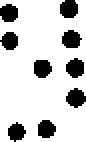
A Figura 1 ilustra um dispositivo portátil e um aparelho de carregamento de acordo com uma versão das disposições inventivas.Figure 1 illustrates a portable device and a charging device according to a version of the inventive provisions.
A Figura 2 ilustra uma visão seccional frontal de uma parte do dispositivo portátil e do aparelho de carregamento da Figura 1, em que o dispositivo portátil está acoplado ao aparelho de carregamento de acordo com uma versão das disposições inventivas.Figure 2 illustrates a front sectional view of part of the portable device and the charging device of Figure 1, in which the portable device is coupled to the charging device according to a version of the inventive arrangements.
A Figura 3 ilustra um esquemático para um aparelho de carregamento e um dispositivo portátil de acordo com uma versão das disposições inventivas.Figure 3 illustrates a schematic for a charging device and a portable device according to a version of the inventive provisions.
A Figura 4 ilustra outro esquemático para um aparelho de carregamento e um dispositivo portátil de acordo com uma versão das disposições inventivas.Figure 4 illustrates another schematic for a charging device and a portable device according to a version of the inventive provisions.
A Figura 5 ilustra outro dispositivo portátil e aparelho de carregamento de acordo com uma versão dasFigure 5 illustrates another portable device and charging device according to a version of the
8/31 • · ··· «8/31 • · ··· «
• · • · • · • ·• · • · • · • ·

• · · ·· ·· • · • · *• · · ·· ·· • · • · *
disposições inventivas.inventive provisions.
A Figura 6 ilustra uma visão seccional frontal de uma parte do dispositivo portátil e do aparelho de carregamento da Figura 5 em que o dispositivo portátil é acoplado ao aparelho de carregamento de acordo com uma versão das disposições inventivas.Figure 6 illustrates a front sectional view of part of the portable device and the charging device of Figure 5 in which the portable device is coupled to the charging device according to a version of the inventive arrangements.
A Figura 7 ilustra ainda outro dispositivo portátil e aparelho de carregamento de acordo com uma versão das disposições inventivas.Figure 7 illustrates yet another portable device and charging apparatus according to a version of the inventive arrangements.
A Figura 8 ilustra uma visão seccional frontal de uma parte do dispositivo portátil e do aparelho de carregamento da Figura 7 em que o dispositivo portátil é acoplado ao aparelho de carregamento em uma primeira posição de acordo com uma versão das disposições inventivas.Figure 8 illustrates a front sectional view of part of the portable device and the charging device of Figure 7 in which the portable device is coupled to the charging device in a first position according to a version of the inventive arrangements.
A Figura 9 ilustra uma visão seccional frontal de uma parte do dispositivo portátil e do aparelho de carregamento da Figura 7 em que o dispositivo portátil é acoplado ao aparelho de carregamento em uma segunda posição de acordo com uma versão das disposições inventivas.Figure 9 illustrates a front sectional view of part of the portable device and the charging device of Figure 7 in which the portable device is coupled to the charging device in a second position according to a version of the inventive arrangements.
A Figura 10 ilustra outro esquemático para um aparelho de carregamento e um dispositivo portátil de acordo com uma versão das disposições inventivas.Figure 10 illustrates another schematic for a charging device and a portable device according to a version of the inventive arrangements.
A Figura 11 ilustra ainda outro esquemático para um aparelho de carregamento e um dispositivo portátil de acordo com uma versão das disposições inventivas.Figure 11 illustrates yet another schematic for a charging device and a portable device according to a version of the inventive arrangements.
A Figura 12 ilustra um método para a indicação de uma condição de carregamento de acordo com uma versão das disposições inventivas. EFigure 12 illustrates a method for indicating a loading condition according to a version of the inventive provisions. AND
A Figura 13 ilustra outro método para a indicação deFigure 13 illustrates another method for indicating
3Q3Q
9/319/31

• · • · • « • · • · ·· • · uma condição de carregamento de acordo com uma versão das disposições inventivas.• · • · • «• · · · ·· • · a loading condition according to a version of the inventive provisions.
DESCRIÇÃO DETALHADADETAILED DESCRIPTION
·. :·· • ·* • · • · · • * ···. : ·· • · * • · • · · • * ··
Embora a especificação conclua com reivindicações que definem as características da invenção que são consideradas novos, acredita-se que a invenção será mais bem compreendida de uma consideração da descrição seguinte em conjunto com as figuras de desenho, em que números de referência iguais são repetidos.Although the specification concludes with claims that define the characteristics of the invention that are considered new, it is believed that the invention will be better understood from a consideration of the following description in conjunction with the drawing figures, in which equal reference numbers are repeated.
Como é necessário, versões detalhadas da presente invenção são aqui reveladas; contudo, deve-se compreender que as versões reveladas são meramente exemplares da invenção, que pode ser incorporada de várias formas. Portanto, os detalhes específicos estruturais e funcionais aqui revelados não devem ser interpretados como limitativos, e sim meramente como uma base para as reivindicações e como uma base representativa para ensinar alguém versado na técnica a empregar variadamente a presente invenção em virtualmente qualquer estrutura apropriadamente detalhada. Ainda, os termos e as frases aqui utilizados não pretendem ser limitativos, e sim fornecer uma descrição compreensível da invenção.As required, detailed versions of the present invention are disclosed herein; however, it should be understood that the versions disclosed are merely exemplary of the invention, which can be incorporated in several ways. Therefore, the specific structural and functional details disclosed herein are not to be construed as limiting, but merely as a basis for the claims and as a representative basis for teaching someone skilled in the art to employ the present invention in a variety of virtually any appropriately detailed structure. Furthermore, the terms and phrases used herein are not intended to be limiting, but rather to provide an understandable description of the invention.
Os termos o e a, conforme aqui utilizados, são definidos como um ou mais de um. O termo pluralidade, conforme aqui utilizado, é definido como dois ou mais de dois. O termo outro, conforme aqui utilizado, é definido como pelo menos um segundo ou mais. Os termos incluir e/ou ter, conforme aqui utilizados, são definidos como compreendidos {isto é, linguagem aberta). O termo acoplado, conforme aqui utilizado, é definido como conectado, embora â\The terms o and a, as used herein, are defined as one or more than one. The term plurality, as used herein, is defined as two or more than two. The term other, as used herein, is defined as at least one second or more. The terms include and / or have, as used herein, are defined as understood (i.e., open language). The term coupled, as used here, is defined as connected, although â \
10/31 • · ·» · • » * · • 9 9 • * • · ··· *10/31 • · · »· •» * · • 9 9 • * • · ··· *
••
9 não necessariamente diretamente, e não necessariamente mecanicamente. Os termos programa, aplicação de software, e assemelhados, conforme aqui utilizados, são definidos como uma seqüência de instruções projetadas para execução em um sistema de computador. 0 programa, programa de computador, ou aplicação de software poderão incluir uma sub-rotina, uma função, um procedimento, um método objeto, uma implementação objeto, uma aplicação executável, um applet, um servlet, um código fonte, um código objeto, uma biblioteca partilhada/biblioteca dinâmica e/ou outra seqüência de instruções projetadas para execução em um sistema de computador.9 not necessarily directly, and not necessarily mechanically. The terms program, software application, and the like, as used herein, are defined as a sequence of instructions designed for execution on a computer system. The program, computer program, or software application may include a subroutine, a function, a procedure, an object method, an object implementation, an executable application, an applet, a servlet, a source code, an object code, a shared library / dynamic library and / or other sequence of instructions designed to run on a computer system.
Com referência à Figura 1, é mostrado um aparelho 100 para a indicação de uma condição de carregamento. Em uma versão da invenção, o aparelho 100 pode ser uma unidade de carregamento para carregar um dispositivo portátil 110, como um telefone celular. Quando o dispositivo portátil 110 está acoplado ao aparelho 100, o aparelho 100 pode fornecer corrente de carregamento para o dispositivo portátil 110. O aparelho 100 não é limitado a carregar telefones celulares, contudo, poi s o apare lho 100 pode ser ut i 1 i zado para carregar qualquer unidade portátil capaz de receber uma corrente de carregamento. Como é conhecido na tecnologia, o aparelho 100 pode ser utilizado para carregar o dispositivo portátil 110 até um nível predeterminado, como o nível de carregamento integral, conforme determinado pelas especificações do dispositivo portátil 110,Referring to Figure 1, an apparatus 100 is shown for indicating a charging condition. In one version of the invention, apparatus 100 may be a charging unit for charging a portable device 110, such as a cell phone. When the handheld device 110 is coupled with the handheld device 100, the handheld device 100 can supply charging current to the handheld device 110. The handheld device 100 is not limited to charging cell phones, however, as the device 100 can be used to charge any portable unit capable of receiving a charging current. As is known in the art, apparatus 100 may be used to charge the portable device 110 to a predetermined level, such as the full charge level, as determined by the specifications of the portable device 110,
Em uma disposição, o aparelho 100 pode ter uma base 112 que pode incluir uma cavidade 114 para receber o dispositivo portátil 110. O aparelho 100 também pode ηIn one arrangement, apparatus 100 may have a base 112 which may include a cavity 114 for receiving portable apparatus 110. Apparatus 100 may also η
11/31 • · ·« «11/31 • · · ««
'J «'J «

incluir uma primeira superfície 116, na qual um ou mais contactos 118 e um ou mais eletromagnetos 120 podem ser posicionados. Além disso, o dispositivo portátil 110 poderá incluir um ou mais contactos correspondentes 122 e um ou mais componentes magneticamente suscetíveis 124. Para fins da invenção, um componente magneticamente suscetível pode ser qualquer material que poderá ser atraído ou repelido por um campo magnético gerado pelo eletromagneto 120. Como um exemplo, o componente magneticamente suscetível 124 pode ser um metal não magnetizado ou um magneto. Quando o dispositivo portátil 110 está acoplado ao aparelho 100, os contactos 118 do aparelho 100 podem engajar os contactos 122 da unidade portátil 110, que pode permitir ao aparelho 100 fornecer uma corrente de carregamento para a unidade portátil 110.include a first surface 116, on which one or more contacts 118 and one or more electromagnets 120 can be positioned. In addition, the portable device 110 may include one or more corresponding contacts 122 and one or more magnetically susceptible components 124. For the purposes of the invention, a magnetically susceptible component can be any material that may be attracted or repelled by a magnetic field generated by the electromagnet 120. As an example, the magnetically sensitive component 124 may be a non-magnetized metal or a magnet. When the portable device 110 is coupled to the apparatus 100, the contacts 118 of the apparatus 100 may engage the contacts 122 of the portable unit 110, which may allow the apparatus 100 to supply a charging current to the portable unit 110.
Neste exemplo, o eletromagneto 120 pode gerar um campo magnético que pode atrair o componente magneticamente suscetível 124 do dispositivo portátil 110, Aqui, o componente magneticamente suscetível 124 pode ser um metal não magnetizado ou um magneto de pólo oposto quando comparado ao campo magnético gerado. Esta atração pode ajudar a afixar o dispositivo portátil 110 ao aparelho 100 à medida que o dispositivo portátil 110 está sendo carregado. Uma vez carregado o dispositivo portátil 110 a um nível predeterminado, o campo magnético gerado pelo eletromagneto 120 pode ser removido, o que pode permitir ao usuário facilmente remover o dispositivo portátil 110 do aparelho 100. Este processo, que será ainda mais descrito abaixo, pode dar uma indicação táctil sobre a situação de carregamento do dispositivo portátil 110. Isto é, se o <33 ·· • « :*7 f · V.In this example, the electromagnet 120 can generate a magnetic field which can attract the magnetically sensitive component 124 of the portable device 110, Here, the magnetically sensitive component 124 can be a non-magnetized metal or a magnet with the opposite pole when compared to the generated magnetic field. This attraction can help to attach the portable device 110 to the apparatus 100 as the portable device 110 is being charged. Once the portable device 110 is charged to a predetermined level, the magnetic field generated by the electromagnet 120 can be removed, which can allow the user to easily remove the portable device 110 from the apparatus 100. This process, which will be further described below, can give a tactile indication of the charging status of the portable device 110. That is, if the <33 ·· • «: * 7 f · V.
• · ·.· • ·• · ·. · • ·
12/31 ·· ·· usuário tentar remover o dispositivo portátil 110 do aparelho 100 antes do dispositivo portátil 110 estar carregado até o nível predeterminado, o usuário poderá encontrar dificuldade (se não impossibilidade) em fazê-lo. Inversamente, se o dispositivo portátil 110 foi carregado até um nível superior ao nível predeterminado, o usuário encontrará facilidade para remover o dispositivo portátil 110 do aparelho 100 porque o campo magnético gerado foi eliminado ou pelo menos substancialmente eliminado. É compreendido que a invenção de modo algum é limitada a este exemplo particular, pois outras versões estão dentro da contemplação das disposições inventivas. Algumas dessas versões alternativas serão descritas abaixo.12/31 ·· ·· user attempting to remove handheld device 110 from device 100 before handheld device 110 is charged to the predetermined level, the user may find it difficult (if not impossible) to do so. Conversely, if the portable device 110 has been charged to a higher level than the predetermined level, the user will find it easy to remove the portable device 110 from the apparatus 100 because the generated magnetic field has been eliminated or at least substantially eliminated. It is understood that the invention is by no means limited to this particular example, as other versions are within the scope of the inventive provisions. Some of these alternative versions will be described below.
Com referência à Figura 2, é mostrada uma visão seccional frontal do dispositivo portátil 110 acoplado ao aparelho 100. Para mostrar os componentes a serem discutidos, uma parte da frente do aparelho 100 foi removida, e apenas uma parte do dispositivo portátil 110 é representada. Como pode ser observado, os contactos 122 do dispositivo portátil 110 são eletricamente acoplados aos contactos 118 do aparelho 100, que podem permitir que a corrente de carregamento flua para o dispositivo portátil 110. Adicionalmente, o aparelho 110 pode engajar eletromagneticamente o dispositivo portátil 110. Especificamente, o eletromagneto 120 pode ser energizado e pode atrair o componente magneticamente suscetível 124 do dispositivo portátil 110. O termo engajar eletromagneticamente pode significar o processo de utilizar um campo magnético para afixar o dispositivo portátil ao aparelho 100 para o fim de fornecer ao usuário umaReferring to Figure 2, a front sectional view of the portable device 110 coupled to the device 100 is shown. To show the components to be discussed, a front part of the device 100 has been removed, and only a part of the portable device 110 is shown. As can be seen, the contacts 122 of the portable device 110 are electrically coupled to the contacts 118 of the device 100, which can allow the charging current to flow into the portable device 110. In addition, the device 110 can electromagnetically engage the portable device 110. Specifically, the electromagnet 120 can be energized and can attract the magnetically susceptible component 124 of the handheld device 110. The term electromagnetically engaging can mean the process of using a magnetic field to affix the handheld device to the device 100 in order to provide the user with a

13/31 • ·« • ·13/31 • · «• ·

• · • · • · • ♦ ·· • · ··· • · • · · • · 1 • · · · indicação táctil sobre a situação do carregamento do dispositivo portátil 110.• · • · • · · · · · · · · ··· • · · · · · · 1 · · · · tactile indication about the charging status of the portable device 110.
À medida que o dispositivo portátil 110 é carregado até o nível predeterminado, o aparelho 100 pode eventualmente desacoplar eletromagneticamente o dispositivo portátil 110. Uma vez desacoplado eletromagneticamente, o usuário pode remover o dispositivo portátil 110 do aparelho 100. O termo desacoplar eletromagneticamente pode significar o processo de eliminar o campo magnético, quer substancialmente instantaneamente ou através de um enfraquecimento gradativo, para permitir ao usuário remover o dispositivo portátil 110 do aparelho 100 quando o dispositivo portátil 100 foi carregado até um nível predeterminado.As the portable device 110 is charged to the predetermined level, the device 100 may eventually electromagnetically decouple the portable device 110. Once electromagnetically decoupled, the user can remove the portable device 110 from the device 100. The term electromagnetically decouple can mean the process of eliminating the magnetic field, either substantially instantly or through a gradual weakening, to allow the user to remove handheld device 110 from device 100 when handheld device 100 has been charged to a predetermined level.
Com referência à Figura 3, são mostrados vários componentes do aparelho 100 e do dispositivo portátil 110. Uma fonte de energia 125 pode fornecer corrente de carregamento para o aparelho 100. Em uma disposição, o aparelho 100 pode incluir um circuito de indicação 126 tendo pelo menos um eletromagneto 120, um circuito de controle de carga 128 para controlar a corrente de carregamento para o dispositivo portátil 110, e um processador 130 que pode controlar a operação tanto do circuito de indicação 126 como do circuito de controle de carga 128. O circuito de indicação 126 pode ser acoplado à entrada da fonte de energia 125 e pode, por exemplo, incluir um comutador Ax e um comutador A2 correspondente, que podem estar localizados em lados opostos do eletromagneto 120. Contudo, é compreendido que a invenção não é limitada a este circuito de indicação particular 126, â£Referring to Figure 3, various components of the apparatus 100 and the portable device 110 are shown. A power source 125 may provide charging current for the apparatus 100. In one arrangement, the apparatus 100 may include an indication circuit 126 having at least minus an electromagnet 120, a charge control circuit 128 to control the charging current for the portable device 110, and a processor 130 that can control the operation of both indication circuit 126 and charge control circuit 128. The circuit Indicator 126 can be coupled to the input of the power source 125 and can, for example, include a switch A x and a corresponding switch A 2 , which can be located on opposite sides of the electromagnet 120. However, it is understood that the invention does not is limited to this particular indication circuit 126, £
14/31 • · ·· • · pois outros esquemas adequados podem ser utilizados com a invenção.14/31 • · ·· • · as other suitable schemes can be used with the invention.
« ··· • · ♦ • · ·· • · · • β · · * · « · • · • · • · ·· * • · ··«··· • · ♦ • · ·· • · · • β · · * ·« · • · • · · ·· * • · ··
O eletromagneto 120 é mostrado como estando posicionado a alguma distância do dispositivo portátil 110, o que foi feito para produzir um diagrama que é mais fácil de seguir. Apesar disso, a Figura 3 meramente serve para ilustrar exemplos dos circuitos que podem ser implementados na invenção e, como tal, não pode ser utilizada para limitar o posicionamento do eletromagneto 120.Electromagnet 120 is shown to be positioned some distance from handheld device 110, which was done to produce a diagram that is easier to follow. Nevertheless, Figure 3 merely serves to illustrate examples of the circuits that can be implemented in the invention and, as such, cannot be used to limit the positioning of the electromagnet 120.
O processador 130 pode controlar a operação do circuito de indicação 12 6, por exemplo, ao manipular os comutadores Αχ e A2 (observe que as conexões efetivas são apenas parcialmente ilustradas para limitar confusão quando da revisão da Figura 3) . Ao controlar os comutadores Αχ e A2, o processador 130 pode direcionar a corrente através do eletromagneto 120, o que pode fazer com que o eletromagneto 120 gere um campo magnético de atração com relação ao componente magneticamente suscetível 124 (ver as Figuras 1 e 2 do dispositivo portátil 110).Processor 130 can control the operation of indication circuit 126, for example, by manipulating switches Αχ and A 2 (note that the actual connections are only partially illustrated to limit confusion when reviewing Figure 3). By controlling switches Αχ and A 2 , processor 130 can direct current through electromagnet 120, which can cause electromagnet 120 to generate a magnetic attraction field with respect to magnetically susceptible component 124 (see Figures 1 and 2 of the portable device 110).
circuito de controle de carga 12 8, pode, por exemplo, incluir um resistor de sentir Rs, um transistor de efeito de campo (FET) 132, um diodo de bloqueio 134 e uma entrada 136. Como é conhecido na técnica, o resistor de sentir Rs, através de duas entradas, e da entrada 136, podem permitir ao processador 130 monitorar o carregamento do dispositivo portátil 110. 0 processador 13 0 pode fazer ajustamentos na quantidade de corrente de carregamento que flui para o dispositivo portátil 110 ao controlar o FET 132. A corrente de carregamento pode fluir através de um contacto B+ e para uma ou mais células 138 do dispositivo âQ>load control circuit 12 8, can, for example, include a sensing resistor R s , a field effect transistor (FET) 132, a blocking diode 134 and an input 136. As is known in the art, the resistor sensing R s , through two inputs, and input 136, can allow processor 130 to monitor the loading of the portable device 110. The processor 130 can make adjustments to the amount of charging current flowing to the portable device 110 by controlling o FET 132. The charging current can flow through a B + contact and into one or more cells 138 of the âQ> device
15/3115/31

• · • · • ♦ • · portátil 110. Embora não seja ilustrado, aqueles versados na técnica apreciarão que o processador 13 0 pode ter conversores analógicos-digital (A/D) para converter digitalmente as entradas descritas acima. Também é compreendido que a invenção não é limitada a este circuito de controle de carga particular 128, pois outros esquemas adequados podem ser empregados com a invenção.• · · · ♦ • · portable 110. Although not illustrated, those skilled in the art will appreciate that the 13 0 processor can have analog-to-digital (A / D) converters to digitally convert the inputs described above. It is also understood that the invention is not limited to this particular load control circuit 128, as other suitable schemes can be employed with the invention.
O aparelho 100 também pode incluir um sensor 140. O sensor 140 pode incluir um fornecedor de voltagem Vs, um resistor de empuxo Rx, um primeiro nodo 142, um segundo nodo 144 e outro resistor R2. 0 sensor 14 0 possui uma entrada desemboca na saída/entrada (I/O) do processador 130. O sensor 140 pode sinalizar o processador 130 quando o dispositivo portátil 110 é acoplado ou removido do aparelho 100. Por exemplo, quando o dispositivo portátil 110 é acoplado ao aparelho 100, um circuito pode ser completado através do primeiro e do segundo nodos 142, 144, que o processador 130 pode detectar. De modo similar, se o dispositivo portátil 110 é removido do aparelho 100, o circuito através do primeiro e do segundo nodos 142, 144 é interrompido, e o processador 130 pode identificar a modificação. Mais uma vez, a invenção não é limitada a este sensor 140 particular, pois outros esquemas adequados podem ser implementados na invenção.Apparatus 100 may also include a sensor 140. Sensor 140 may include a voltage supply V s , a surge resistor R x , a first node 142, a second node 144 and another resistor R 2 . The sensor 14 0 has an input leading to the output / input (I / O) of processor 130. Sensor 140 can signal processor 130 when handheld 110 is attached or removed from device 100. For example, when handheld 110 is coupled to apparatus 100, a circuit can be completed through the first and second nodes 142, 144, which processor 130 can detect. Similarly, if portable device 110 is removed from apparatus 100, the circuit through first and second nodes 142, 144 is interrupted, and processor 130 can identify the change. Again, the invention is not limited to this particular sensor 140, as other suitable schemes can be implemented in the invention.
Com referência à Figura 4, é mostrado outro exemplo de vários componentes do aparelho 100 e do dispositivo portátil 110. A disposição do aparelho 100 e do dispositivo portátil 110 é similar àquela mostrada na Figura 3. Isto é, o aparelho na Figura 4 pode ter um circuito de indicação 126, um circuito de controle de carga 128, um sensor 140, eReferring to Figure 4, another example of various components of the apparatus 100 and the portable device 110 is shown. The arrangement of the apparatus 100 and the portable device 110 is similar to that shown in Figure 3. That is, the apparatus in Figure 4 may have an indication circuit 126, a load control circuit 128, a sensor 140, and
3Ί16/31 ·· · • · • · • · · • · ·· «· ·3Ί16 / 31 ·· · • · · · · · · · ··· · · ·

todos os componentes que compõem esses circuitos. A principal diferença é que o circuito de indicação 126 daall the components that make up these circuits. The main difference is that the indication circuit 126 of the
Figura 4 está em série com o circuito de controle de cargaFigure 4 is in series with the load control circuit
128. O circuito de indicação 126 da Figura 3 pode ramificar ou estar em paralelo com o circuito de controle de carga ··128. Indication circuit 126 in Figure 3 can branch or be in parallel with the load control circuit ··
128.128.
Com referência de volta à Figura 3, quando a fonte de energia 125 está fornecendo corrente de carregamento para o aparelho 100, corrente também pode ser fornecida para o circuito de indicação 126. Por exemplo, o processador 13 0 pode fechar os comutadores Ai e A2, e o circuito de indicação 126 pode fornecer uma corrente de engajamento para o eletromagneto 120. Este processo pode fazer com que o eletromagneto 120, por exemplo, gere um campo magnético de atração com relação ao dispositivo portátil 110. Para os fins da invenção, o termo corrente de engajamento pode significar corrente que é fornecida ao eletromagneto 120 que faz com que o eletromagneto 120 gere um campo magnético.Referring back to Figure 3, when power source 125 is supplying charging current to apparatus 100, current may also be supplied to indication circuit 126. For example, processor 130 may close switches Ai and A 2 , and indication circuit 126 can provide an engagement current for electromagnet 120. This process can cause electromagnet 120, for example, to generate a magnetic attraction field with respect to portable device 110. For the purposes of the invention , the term engagement current can mean current that is supplied to electromagnet 120 which causes electromagnet 120 to generate a magnetic field.
Conforme foi observado anteriormente, o aparelho 100 pode ser utilizado para carregar o dispositivo portátil 110 a um nível predeterminado, como a capacidade de carga de bateria predeterminada. Este nível predeterminado pode ser o nível máximo, como a capacidade de carga de bateria máxima, ou algo inferior. Quando o campo magnético é produzida, o campo gerado pode permanecer a um nível substancialmente fixo à medida que o dispositivo portátil 110 é carregado no sentido do nível predeterminado. A razão para o nível substancialmente fixo do campo gerado é porque o circuito de indicação 126 é independente do circuito de âgAs noted earlier, apparatus 100 can be used to charge portable device 110 to a predetermined level, such as the predetermined battery charge capacity. This predetermined level can be the maximum level, such as the maximum battery charge capacity, or something less. When the magnetic field is produced, the generated field can remain at a substantially fixed level as the portable device 110 is charged towards the predetermined level. The reason for the substantially fixed level of the generated field is because the indication circuit 126 is independent of the âg circuit
17/31 ·» ·· ·· · • · · • · ·· • · · • ·17/31 · »·· ·· · • · · • · ·· • · · · ·

• · ·· • · • · • · ·· • · · ·· controle de carga 128. Como é conhecido na tecnologia, à medida que a bateria (como aquela que pode ser acoplada ao dispositivo portátil 110) é carregada, a quantidade de corrente de carregamento que é fornecida à bateria poderá decrescer. Este decréscimo na corrente que poderá ocorrer no circuito de controle de carga 128 não afetará a quantidade de corrente que atinge o circuito de indicação 126.Charge control 128. As is known in technology, as the battery (such as the one that can be attached to the portable device 110) is charged, the amount charging current that is supplied to the battery may decrease. This decrease in current that may occur in the load control circuit 128 will not affect the amount of current reaching the indication circuit 126.
Com referência à Figura 4, à medida que o dispositivo portátil 110 é carregado até o nível predeterminado, a corrente de carregamento fornecida para o dispositivo portátil 110 poderá decrescer, como foi descrito acima. No entanto, nesta disposição, se os comutadores Ax e A2 são fechados, a potência do campo magnético gerado pelo eletromagneto 120 também poderá decrescer também. Como um exemplo, o campo magnético poderá ser um campo magnético de atração em relação ao dispositivo portátil 110. À medida que a quantidade de corrente de carregamento cai em resposta ao dispositivo portátil 110 ser carregado até o nível predeterminado, a potência do campo magnético de atração também pode decrescer. O usuário pode sentir a queda na atração entre o aparelho 100 e o dispositivo portátil 110, que pode fornecer uma indicação de que o dispositivo portátil está se aproximando de sua capacidade de carga.Referring to Figure 4, as the portable device 110 is charged to the predetermined level, the charging current supplied to the portable device 110 may decrease, as described above. However, in this arrangement, if switches A x and A 2 are closed, the power of the magnetic field generated by electromagnet 120 may also decrease as well. As an example, the magnetic field could be a magnetic attraction field in relation to the portable device 110. As the amount of charging current drops in response to the portable device 110 being charged to the predetermined level, the power of the magnetic field of attraction can also decrease. The user can feel the drop in attraction between the device 100 and the handheld device 110, which can provide an indication that the handheld device is approaching its load capacity.
O aparelho 100 também pode ser projetado para produzir um campo magnético de repulsão, que pode ser utilizado para auxiliar no carregamento do dispositivo portátil 110. Um exemplo dessa construção é ilustrado nas Figuras 5 e 6. Aqui, o dispositivo portátil 110 podeThe apparatus 100 can also be designed to produce a repulsive magnetic field, which can be used to assist in charging the portable device 110. An example of this construction is illustrated in Figures 5 and 6. Here, the portable device 110 can
18/31 • · * • · · • · incluir uma ou mais extensões 14 6 que podem incluir uma superfície superior 148. Em uma disposição, os contactos 122 para o dispositivo portátil 110 podem estar localizados na superfície superior 148 das extensões 146. Como outro exemplo, o componente magneticamente suscetível 124 pode ser afixado próximo da parte inferior do dispositivo portátil 110. O componente magneticamente suscetível 124 pode ser um magneto que tem um pólo igual com relação ao campo magnético que o eletromagneto 120 do aparelho 100 irá gerar.18/31 • · * • · · • · include one or more extensions 14 6 which may include an upper surface 148. In one arrangement, contacts 122 for portable device 110 may be located on the upper surface 148 of extensions 146. As another example, the magnetically susceptible component 124 may be affixed near the bottom of the portable device 110. The magnetically sensitive component 124 may be a magnet that has an equal pole with respect to the magnetic field that the electromagnet 120 of the apparatus 100 will generate.
Como é mostrado na Figura 5, o eletromagneto 120 pode ser posicionado em uma primeira superfície 116 do aparelho 100. Os contactos 118 que correspondem aos contactos 122 do dispositivo portátil 110 podem estar localizados em uma segunda superfície 152 do aparelho 100. Os contactos 118, como eles estão ocultos da vista, são representados por contornos serrilhados. Nesta disposição, a primeira superfície 116 pode ser oposta à segunda superfície 152. O aparelho 100 também pode ter uma abertura frontal 151 para receber o dispositivo portátil 110 e uma cavidade 153 para receber o dispositivo portátil 110 quando o aparelho 100 desacopla eletromagneticamente o dispositivo portátil 110. O eletromagneto 120 pode ser posicionado dentro desta cavidade 153.As shown in Figure 5, the electromagnet 120 can be positioned on a first surface 116 of the apparatus 100. The contacts 118 corresponding to the contacts 122 of the portable device 110 can be located on a second surface 152 of the apparatus 100. Contacts 118, as they are hidden from view, they are represented by serrated outlines. In this arrangement, the first surface 116 can be opposite the second surface 152. The apparatus 100 may also have a front opening 151 for receiving the portable device 110 and a cavity 153 for receiving the portable device 110 when the apparatus 100 electromagnetically decouples the portable device. 110. Electromagnet 120 can be positioned inside this cavity 153.
Com referência à Figura 6, é mostrada uma visão seccional frontal do dispositivo portátil 110 acoplado ao aparelho 100 {apenas uma parte do dispositivo portátil 110 é ilustrada). 0 dispositivo portátil 110 pode ser acoplado ao aparelho 100 ao deslizar o dispositivo portátil 110 dentro da abertura frontal 151 do aparelho 100. NesteWith reference to Figure 6, a front sectional view of the portable device 110 coupled to the apparatus 100 is shown (only a part of the portable device 110 is illustrated). The portable device 110 can be coupled to the device 100 by sliding the portable device 110 into the front opening 151 of the device 100. In this case
3C3C
19/3119/31

• · • · • * ··· · • · · ·· · · • · · ♦ · · · • · • ·· • · · • · · · • · · · « · · ·· · exemplo, o eletromagneto 120 pode gerar um campo magnético que repele o componente magneticamente suscetível 124 do dispositivo portátil 110. Isto é, o componente magneticamente suscetível 124 pode ser um magneto que tem um pólo igual quando comparado ao campo magnético gerado. Esta repulsão pode estimular o dispositivo portátil 110 para cima tal que os contactos 122 do dispositivo portátil 110 são eletricamente acoplados aos contactos 118 do aparelho 100 para permitir que a corrente de carregamento seja fornecida para o dispositivo portátil 110. Neste exemplo, o aparelho 100 engajou eletromagneticamente o dispositivo portátil 110.• · · · · · · · · · · · · · · · · · · · · · · · · · · · · · · · · · · · · · · · · · · · · · · · · · 120 can generate a magnetic field that repels the magnetically sensitive component 124 of the portable device 110. That is, the magnetically sensitive component 124 can be a magnet that has an equal pole when compared to the generated magnetic field. This repulsion can stimulate the portable device 110 upwards such that the contacts 122 of the portable device 110 are electrically coupled to the contacts 118 of the apparatus 100 to allow the charging current to be supplied to the portable device 110. In this example, the apparatus 100 engaged electromagnetically the portable device 110.
Em uma disposição, o aparelho 100 pode ter um ou mais segmentos de bloqueio 154 (ver também a Figura 5) . Quando o dispositivo portátil 110 é eletromagneticamente engajado ao aparelho 100, os segmentos de bloqueio 154 podem impedir o movimento à frente das extensões 146 do dispositivo portátil 110. Esta obstrução pode impedir a remoção do dispositivo portátil 110 do aparelho 100 quando o eletromagneto 120 estiver gerando o campo magnético de repulsão. Quando o campo magnético de repulsão é removido ou pelo menos substancialmente enfraquecido, o dispositivo portátil 110 poderá cair, que então permitirá que as extensões 146 liberem os segmentos de bloqueio 154. Neste ponto, o aparelho 100 desacoplou eletromagneticamente o dispositivo portátil 110, e o dispositivo portátil 110 pode ser deslocado para a frente para permitir sua retirada do aparelho 100.In one arrangement, apparatus 100 may have one or more locking segments 154 (see also Figure 5). When handheld 110 is electromagnetically engaged with apparatus 100, locking segments 154 may prevent movement in front of extensions 146 of handheld 110. This obstruction may prevent removal of handheld 110 from apparatus 100 when electromagnet 120 is generating the magnetic repulsion field. When the repulsion magnetic field is removed or at least substantially weakened, the portable device 110 may fall, which will then allow the extensions 146 to release the lock segments 154. At this point, the apparatus 100 has electromagnetically decoupled the portable device 110, and the portable device 110 can be moved forward to allow removal from device 100.
Embora não seja aqui mostrado, aqueles versados na técnica apreciarão que as características de suporteAlthough not shown here, those skilled in the art will appreciate that the supporting characteristics
20/31 ·· ··· • · · • · ·· • » · • · · · • ·20/31 ·· ··· • · · • · ·· • »· • · · · • ·

···· estrutural (além de ou em substituição à cavidade 15 3) poderão ser acrescentadas ao dispositivo portátil 110 e/ou ao aparelho 100. Essas características de suporte podem ajudar a estabilizar o dispositivo portátil 110 à medida que o aparelho 100 eletromagneticamente engaja e desacopla o dispositivo portátil 110. Ademais, é compreendido que a invenção não está, de modo algum, limitada à estrutura ilustrada nas Figuras 5 e 6. Isto é, tanto o dispositivo portátil 110 como o aparelho 100 podem ser construídos de várias maneiras para implementar o carregamento do dispositivo portátil 110 utilizando um campo magnético de repulsão.···· structural (in addition to or replacing cavity 15 3) can be added to the portable device 110 and / or the device 100. These support features can help stabilize the portable device 110 as the device 100 electromagnetically engages and uncouples the portable device 110. Furthermore, it is understood that the invention is by no means limited to the structure illustrated in Figures 5 and 6. That is, both the portable device 110 and the apparatus 100 can be constructed in various ways to implement charging of portable device 110 using a repulsion magnetic field.
Para produzir o campo magnético de repulsão, os componentes ilustrados nas Figuras 3 e 4 podem ser utilizados. Para produzir a força de repulsão, o componente magneticamente suscetível 124 do dispositivo portátil 110 pode ser um magneto de pólo igual com relação ao eletromagneto 120. De acordo com a discussão relacionada às Figuras 3 e 4, o campo magnético de repulsão pode permanecer em um nível substancialmente fixo à medida que o dispositivo portátil 110 é carregado até um nível predeterminado. Alternativamente, o campo magnético de repulsão pode diminuir em potência à medida que o dispositivo portátil 110 é carregado até um nível predeterminado.To produce the repulsion magnetic field, the components illustrated in Figures 3 and 4 can be used. To produce the repulsion force, the magnetically sensitive component 124 of the portable device 110 may be a magnet with the same pole with respect to the electromagnet 120. According to the discussion related to Figures 3 and 4, the magnetic repulsion field may remain in one substantially fixed level as the portable device 110 is charged to a predetermined level. Alternatively, the repulsion magnetic field may decrease in power as the portable device 110 is charged to a predetermined level.
Com referência à Figura 7, é mostrado um outro exemplo de um dispositivo portátil 110 e de um aparelho 100 para indicação de uma condição de carregamento. Neste exemplo, o aparelho 100 e o dispositivo portátil 110 podem ser um tanto similares estruturalmente ao aparelho 100 e aoReferring to Figure 7, another example of a portable device 110 and an apparatus 100 is shown for indicating a charging condition. In this example, apparatus 100 and portable device 110 may be somewhat structurally similar to apparatus 100 and the
21/31 • * · *21/31 • * · *
• · • · • · • · • ·· • · * • · ·· • · · · • · · ·· · • · ·· t :· · · · · · · · · · · · · · · · · · · · · · · · ·
·· ·· dispositivo portátil 110 da Figura 5. Isto é, o dispositivo portátil 110 pode ter uma ou mais extensões 14 6 e um componente magneticamente suscetível 124. Adicionalmente, o apare lho 100 pode incluir uma cavidade 153 e um eletromagneto 120 posicionados no interior da cavidade 153 na primeira superfície 116. Contudo, aqui os contactos 122 para o dispositivo portátil 110 podem estar localizados na parte inferior ou próxima dela, do dispositivo portátil 110. Outrossim, os contactos 118 do aparelho 100 podem ser posicionados na primeira superfície 116.·· ·· portable device 110 of Figure 5. That is, portable device 110 may have one or more extensions 146 and a magnetically susceptible component 124. Additionally, apparatus 100 may include a cavity 153 and an electromagnet 120 positioned in the inside of cavity 153 on the first surface 116. However, here the contacts 122 for the portable device 110 can be located at or near the bottom of the portable device 110. Furthermore, the contacts 118 of the apparatus 100 can be positioned on the first surface 116 .
Nesta disposição, o aparelho 100 pode gerar um campo magnético de atração, e quando o dispositivo portátil 110 é carregado até um nível predeterminado, o aparelho 100 pode gerar um campo magnético de repulsão. Para efetuar tal processo, o componente magneticamente suscetível 124 pode ser um magneto tendo um pólo predeterminado.In this arrangement, apparatus 100 may generate a magnetic attraction field, and when the portable device 110 is charged to a predetermined level, apparatus 100 may generate a repulsion magnetic field. To carry out such a process, the magnetically sensitive component 124 may be a magnet having a predetermined pole.
Com referência à Figura 8, o aparelho 100 pode engajar eletromagneticamente o dispositivo portátil 110 em uma primeira posição em que o eletromagneto 120 está gerando um campo magnético de atração com relação ao componente magneticamente suscetível 124. Apenas uma parte do dispositivo portátil 110 é mostrado aqui, e parte do aparelho 100 foi removida para mostrar mais claramente alguns dos componentes. Os contactos 118 do aparelho 100 podem ser eletricamente acoplados aos contactos 122 do dispositivo portátil 110, assim permitindo que a corrente de carregamento flua para o dispositivo portátil 110.With reference to Figure 8, the apparatus 100 can electromagnetically engage the handheld device 110 in a first position where the electromagnet 120 is generating a magnetic field of attraction with respect to the magnetically susceptible component 124. Only part of the handheld device 110 is shown here , and part of the apparatus 100 has been removed to show some of the components more clearly. The contacts 118 of the apparatus 100 can be electrically coupled to the contacts 122 of the portable device 110, thus allowing the charging current to flow into the portable device 110.
Com referência à Figura 9, o aparelho 100 pode engajar eletromagneticamente o dispositivo portátil 110 em uma segunda posição. Este processo pode ocorrer quando oWith reference to Figure 9, the apparatus 100 can electromagnetically engage the portable device 110 in a second position. This process can occur when the
22/3122/31

• *· · • · · ·♦ · · • · · • · · · • · * · • · · •« ·· • · · »· ·· · ·· ·· dispositivo portátil 110 foi carregado até um nível ou capacidade predeterminados. Quando o dispositivo portátil 110 está na segunda posição, o usuário recebe uma indicação de que o dispositivo portátil 110 está integralmente carregado. Para estimular o dispositivo portátil 110 na segunda posição, o eletromagneto 120 pode gerar um campo magnético de repulsão com relação ao componente magneticamente suscetível 124.• * · · • · · · · · · · · · · · · · · · · · · · · · · · · · ··· ·· ·· portable device 110 has been charged to a level or predetermined capacity. When the handheld 110 is in the second position, the user receives an indication that the handheld 110 is fully charged. To stimulate the portable device 110 in the second position, the electromagnet 120 can generate a magnetic repulsion field with respect to the magnetically susceptible component 124.
Nesta disposição, as projeções 146 podem repousar contra uma superfície interna 156 do aparelho 100 para ajudar a manter o dispositivo portátil 110 no lugar quando o campo magnético de repulsão estiver sendo gerado. Nesta segunda posição, os contactos 118 e os contactos 122 não são mais eletricamente acoplados, e o fluxo de corrente de carregamento para o dispositivo portátil 110 pode parar, Além disso, o dispositivo portátil 110 pode ser facilmente removido do aparelho 100 ao de sloca-1o para a f rente através de uma abertura 151 do aparelho 100.In this arrangement, the projections 146 can rest against an internal surface 156 of the apparatus 100 to help hold the portable device 110 in place when the repulsion magnetic field is being generated. In this second position, the contacts 118 and the contacts 122 are no longer electrically coupled, and the charging current flow to the portable device 110 can stop. In addition, the portable device 110 can be easily removed from the device 100 to the locking device. 1 forwards through an opening 151 of the apparatus 100.
Embora não seja aqui mostrado, aqueles versados na técnica apreciarão que uma estrutura para suportar o dispositivo portátil 110, além da cavidade 153, pode ser incorporada no dispositivo portátil 110 e/ou no aparelho 100. A estrutura de suporte pode suportar o dispositivo portátil 110 tanto na primeira como na segunda posições. Ademais, é compreendido que a invenção não é limitada ao dispositivo portátil 110 e ao aparelho 100 mostrado nas Figuras 7 a 9, pois outros projetos adequados estão dentro da contemplação das disposições inventivas, Aqueles versados na técnica também apreciarão que o aparelho 100 poderia ser projetado para gerar um campo magnético deAlthough not shown here, those skilled in the art will appreciate that a structure for supporting portable device 110, in addition to cavity 153, can be incorporated into portable device 110 and / or apparatus 100. The support structure can support portable device 110 both in the first and second positions. Furthermore, it is understood that the invention is not limited to the portable device 110 and the device 100 shown in Figures 7 to 9, as other suitable designs are within the scope of the inventive provisions. Those skilled in the art will also appreciate that the device 100 could be designed to generate a magnetic field of
23/31 • · ·· ·· • ·· ·· • · • · • * • · • · • · • · repulsão uma vez o dispositivo portátil 110 tenha sido carregado até o nível predeterminado como uma alternativa ao processo explicado acima.23/31 • · ····· · ·· ·· • · • · • * • · · · · · · · repulsion once the portable device 110 has been charged to the predetermined level as an alternative to the process explained above.
Com referência à Figura 10, é mostrado um circuito para realizar o processo descrito em relação às Figuras 7 a 9. O circuito pode ser como aquele apresentado na Figura 3. O circuito de indicação 126 na Figura 10 pode ser diferente pois ele pode conter dois conjuntos de comutadores, Αχ, A2, Bi, e B2. Os comutadores Ai e A2 podem estar localizados em lados opostos do eletromagneto 120. De modo similar, os comutadores Bi e B2 podem estar posicionados em lados opostos do eletromagneto 120. Os comutadores Αχ e A2, Βχ e B2 podem estar sob o controle do processador 130.With reference to Figure 10, a circuit is shown to perform the process described in relation to Figures 7 to 9. The circuit can be like the one shown in Figure 3. The indication circuit 126 in Figure 10 can be different because it can contain two switch sets, Αχ, A 2 , Bi, and B 2 . Switches Ai and A 2 can be located on opposite sides of electromagnet 120. Similarly, switches Bi and B 2 can be positioned on opposite sides of electromagnet 120. Switches Αχ and A 2 , Βχ and B 2 can be under control of processor 130.
Para gerar o campo magnético de atração, o processador pode fechar os comutadores Αχ e A2 (mantendo os comutadores Βχ e B2 abertos) , o que pode fornecer uma corrente de engajamento para o eletromagneto 12 0 e, como foi descrito anteriormente com relação à Figura 3. Para gerar o campo magnético de repulsão, o processador 130 pode fechar os comutadores Βχ e B2 (mantendo os comutadores Αχ e A2 abertos) . Esta etapa pode fazer com que uma corrente flua em uma direção oposta ao fluxo de corrente quando os comutadores Αχ e A2 estão fechados. 0 processador 13 0 pode abrir os comutadores Αχ e A2 e fechar os comutadores Βχ e B2 quando o dispositivo portátil 110 tiver sido carregado até um nível predeterminado.To generate the magnetic attraction field, the processor can close the Αχ and A 2 switches (keeping the Βχ and B 2 switches open), which can provide an engagement current for the electromagnet 12 0 and, as previously described with respect to to Figure 3. To generate the repulsion magnetic field, processor 130 can close switches Βχ and B 2 (keeping switches Αχ and A 2 open). This step can cause a current to flow in a direction opposite to the current flow when switches Αχ and A 2 are closed. The processor 130 can open the Αχ and A 2 switches and close the Βχ and B 2 switches when the portable device 110 has been charged to a predetermined level.
Com referência à Figura 11, é mostrado outro circuito para realizar o processo descrito com relação às Figuras 7 a 9. Este circuito pode ser como aquele apresentado na Figura 4. Por exemplo, pelo menos parte doReferring to Figure 11, another circuit is shown to perform the process described with respect to Figures 7 to 9. This circuit can be like the one shown in Figure 4. For example, at least part of
24/3124/31
·· da corrente de carregamento que flui para o dispositivo portátil 110 diminui.·· the charging current flowing to the portable device 110 decreases.
Uma vez o dispositivo portátil 110 tenha sido carregado até o nível predeterminado e a corrente de carregamento para ele foi removida, o circuito de indicação 126 ainda poderá fornecer uma corrente de engajamento para o eletromagneto 120 para permitir que ele gere o campo magnético de repulsão. Para fazê-lo, parte do circuito de controle de indicação 126 poderá ramificar ou ficar em paralelo com o circuito de controle de carga 128. Por exemplo, os comutadores Bx e B2 podem ser utilizados para dirigir a corrente em direção oposta àquela fornecida pelos comutadores Ax e A2 com o comutador Bx acoplado ao terra. Esta parte do circuito de indicação 126 pode ser independente do circuito de controle de carga 128, assim permitindo que a potência do campo magnético de repulsão permaneça a um nível substancialmente fixo.Once the portable device 110 has been charged to the predetermined level and the charging current for it has been removed, the indicating circuit 126 may still provide an engagement current for the electromagnet 120 to allow it to generate the repulsion magnetic field. To do this, part of the indicating control circuit 126 may branch or be in parallel with the load control circuit 128. For example, switches B x and B 2 can be used to direct the current in the opposite direction to that supplied switches A x and A 2 with switch B x coupled to ground. This part of the indication circuit 126 can be independent of the load control circuit 128, thus allowing the power of the repulsion magnetic field to remain at a substantially fixed level.
Para realizar os processos descritos em relação às Figuras 7 a 9, é compreendido que a invenção não está de modo algum limitada aos componentes mostrados nas Figuras 10 e 11. Por exemplo, outros circuitos de indicação e de circuitos de controle de carga adequados podem ser utilizados para praticar a invenção. Aqueles versados na técnica também apreciarão que a invenção pode ser projetada tal que o dispositivo portátil 110 é inicialmente repelido • · · : · • · ·· * ·In order to carry out the processes described in relation to Figures 7 to 9, it is understood that the invention is in no way limited to the components shown in Figures 10 and 11. For example, other suitable indication and load control circuits can be used to practice the invention. Those skilled in the art will also appreciate that the invention can be designed such that the portable device 110 is initially repelled • · ·: · • · ·· * ·
25/31 • · · • · ·· • · • · • ·25/31 • · · · · · · · · · · · ·
120 e depois (similar ao 6) . Uma vez para uma primeira posição pelo eletromagneto carregado enquanto nesta primeira posição processo descrito em relação às Figuras 5 e carregado o dispositivo portátil, o eletromagneto 120 pode então gerar um campo magnético de atração, e o dispositivo portátil 110 pode deslocar-se para uma segunda posição no aparelho 100. Ao deslocar-se para a segunda posição, o usuário pode receber uma indicação de que o dispositivo portátil 110 foi carregado. O campo magnético de atração pode ser relativamente fraco para permitir ao usuário remover com facilidade o dispositivo portátil 110 do aparelho 100.120 and later (similar to 6). Once to a first position by the charged electromagnet while in this first position the process described in relation to Figures 5 and the portable device is charged, the electromagnet 120 can then generate a magnetic field of attraction, and the portable device 110 can move to a second position on the device 100. When moving to the second position, the user may receive an indication that the portable device 110 has been charged. The magnetic attraction field can be relatively weak to allow the user to easily remove the portable device 110 from the apparatus 100.
Com referência à Figura 12, é ilustrado um método 1200 para a indicação de uma condição de carregamento. Para descrever o método 1200, referência poderá ser feita às Figuras 1 a 6, embora se j a preciso observar que o método 1200 pode ser praticado em outros sistemas adequados. Na etapa 1210, o método 1200 pode começar. Como é mostrado na etapa 1220, uma unidade de carregamento pode engajar eletromagneticamente um dispositivo portátil tal que o dispositivo portátil é magneticamente estimulado e afixado a pelo menos uma parte da unidade de carregamento. Na etapa 1230, uma corrente de carregamento pode ser fornecida para o dispositivo portátil. Além disso, na etapa 1240, uma corrente de engajamento pode ser fornecida a pelo menos um eletromagneto da unidade de carregamento, que pode fazer com que o eletromagneto gere quer um campo magnético de atração ou um campo magnético de repulsão com relação ao dispositivo portátil.Referring to Figure 12, a method 1200 for indicating a loading condition is illustrated. To describe method 1200, reference may be made to Figures 1 to 6, although it is necessary to note that method 1200 can be practiced in other suitable systems. In step 1210, method 1200 can begin. As shown in step 1220, a charging unit can electromagnetically engage a portable device such that the portable device is magnetically stimulated and affixed to at least part of the charging unit. In step 1230, a charging current can be provided for the portable device. In addition, in step 1240, an engagement current can be supplied to at least one electromagnet from the charging unit, which can cause the electromagnet to generate either a magnetic attraction field or a repulsion magnetic field with respect to the handheld device.
For exemplo, com referência às Figuras 1 a 6, osFor example, with reference to Figures 1 to 6, the
3T3Q
26/31 *26/31 *
« · « · • · ·· ·· • <«·« · • · ·· ·· • <
• <• <
• · « · • · • » comutadores Ai e A2 podem fechados, e uma corrente de engajamento pode ser fornecida ao eletromagneto 120 do aparelho 100. 0 eletromagneto 120 pode então gerar quer um campo magnético de atração ou um campo magnético de repulsão com relação ao dispositivo portátil 110. Dependendo do tipo de campo gerado, o aparelho 100 pode estimular magneticamente o dispositivo portátil 110 na direção de uma parte do aparelho 100. O dispositivo portátil 110 também pode ser afixado a esta parte do aparelho 100. Exemplos incluem as disposições mostradas nas Figuras 2 e 6. Neste ponto, o aparelho 100, através do circuito de controle de carga 128, pode fornecer corrente de carregamento para o dispositivo portátil 110.Switches Ai and A 2 can be closed, and an engagement current can be supplied to electromagnet 120 of apparatus 100. Electromagnet 120 can then generate either a magnetic attraction field or a repulsion magnetic field with with respect to handheld device 110. Depending on the type of field generated, device 100 can magnetically stimulate handheld device 110 towards part of device 100. Handheld device 110 can also be attached to this part of device 100. Examples include the arrangements shown in Figures 2 and 6. At this point, the apparatus 100, through the charge control circuit 128, can supply charging current to the portable device 110.
Com referência de volta ao método 1200 da Figura 12, no bloco de decisão 1250, pode ser determinado se a potência do campo magnético será mantida a um nível substancialmente fixo ou diminuída. Se será um nível substancialmente fixo, na etapa 1260, a potência do campo magnético pode ser mantida ao nível substancialmente fixo à medida que o dispositivo portátil é carregado até o nível predeterminado. Se ela será diminuída, na etapa 1270, a potência do campo magnético pode ser diminuída à medida que o dispositivo portátil é carregado no sentido do nível predeterminado.With reference back to method 1200 of Figure 12, in decision block 1250, it can be determined whether the power of the magnetic field will be maintained at a substantially fixed level or decreased. If it will be a substantially fixed level, in step 1260, the power of the magnetic field can be maintained at a substantially fixed level as the portable device is charged to the predetermined level. If it will be decreased, in step 1270, the power of the magnetic field can be decreased as the handheld is charged towards the predetermined level.
Por exemplo, se é desejado manter a potência do campo magnético (quer de atração ou de repulsão) a um nível substancialmente fixo à medida que o dispositivo portátil 110 está sendo carregado até o nível predeterminado, a configuração do circuito de indicação 126 conforme representado na Figura 3 é adequada. Inversamente, se éFor example, if it is desired to maintain the power of the magnetic field (either of attraction or repulsion) at a substantially fixed level as the portable device 110 is being charged to the predetermined level, the configuration of the indication circuit 126 as shown in Figure 3 is adequate. Conversely, if it is
3g3g
27/3127/31

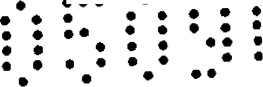
• · • · • · ·· ·· • · • · • · ·· ♦ · • ·· • · • · · • * ·» • · *· · · · · · · · · · · ♦ · · · · · · · · · · · • · *
desejado diminuir a potência do campo magnético (quer de atração ou de repulsão) à medida que o dispositivo portátil 110 é carregado até o nível predeterminado, o circuito de indicação 126 conforme mostrado na Figura 4 pode ser útil.If it is desired to decrease the power of the magnetic field (either of attraction or repulsion) as the portable device 110 is charged to the predetermined level, the indication circuit 126 as shown in Figure 4 can be useful.
Com referência de volta â Figura 12, na etapa 1280, quando o dispositivo portátil é carregado até o nível predeterminado, o dispositivo portátil pode ser eletromagneticamente desacoplado da unidade de carregamento para permitir ao usuário remover o dispositivo portátil da unidade de carregamento. Por exemplo, com referência às Figuras 1 a 6, quando o dispositivo portátil 110 já foi carregado até um nível predeterminado, o aparelho 100 pode eletromagneticamente desacoplar o dispositivo portátil 110. Especificamente com referência às Figuras 3 e 4, quando o dispositivo portátil 110 foi carregado até o nível predeterminado, os comutadores Ax e A2 podem ser abertos, o que interromperá o fluxo da corrente de engajamento para o eletromagneto 120. A remoção desta corrente pode fazer com que o campo magnético gerado entre em colapso, o que pode permitir que o dispositivo portátil 110 seja removido do aparelho 100.Referring back to Figure 12, in step 1280, when the portable device is charged to the predetermined level, the portable device can be electromagnetically decoupled from the charging unit to allow the user to remove the portable device from the charging unit. For example, with reference to Figures 1 to 6, when the portable device 110 has already been charged to a predetermined level, the apparatus 100 can electromagnetically decouple the portable device 110. Specifically with reference to Figures 3 and 4, when the portable device 110 has been charged to the predetermined level, switches A x and A 2 can be opened, which will interrupt the flow of the engagement current to electromagnet 120. Removing this current can cause the generated magnetic field to collapse, which can allow portable device 110 to be removed from apparatus 100.
Em uma disposição, o nível predeterminado pode ser uma capacidade de carga de batería máxima para uma bateria que fornecerá energia para o dispositivo portátil 110. No entanto, o nível predeterminado também poderá ser uma capacidade de carga que estã abaixo da capacidade de carga de bateria máxima.In one arrangement, the predetermined level may be a maximum battery charge capacity for a battery that will supply power to the portable device 110. However, the predetermined level may also be a charge capacity that is below the battery charge capacity maximum.
Passando de volta para a Figura 12, no bloco de decisão 1285, pode ser determinado se o dispositivo portátil foi removido da unidade de carregamento. Se for, aMoving back to Figure 12, in decision block 1285, it can be determined whether the portable device has been removed from the charging unit. If so, the
28/31 •« *♦ ··· • · «28/31 • «* ♦ ··· • ·«
• · ♦ • r · * • ·• · ♦ • r · * • ·

unidade de carregamento pode ser fixada para uma configuração de carregamento predeterminada, como é mostrado na etapa 1290. Se o dispositivo portátil ainda não foi removido, o método 1200 pode continuar no bloco de decisão 1285. Após a etapa 1290, o método 1200 pode terminar na etapa 1295.The charging unit can be fixed to a predetermined charging configuration, as shown in step 1290. If the handheld has not yet been removed, method 1200 can continue in decision block 1285. After step 1290, method 1200 can end in step 1295.
Um exemplo da etapa de fixação 12 9 0 será apresentado. Com referência às Figuras 3 e 4 e conforme observado anteriormente, quando o dispositivo portátil 110 é carregado até o nível predeterminado, os comutadores Ai e A2 podem abrir, o que elimina o campo magnético. Quando o usuário retira o dispositivo portátil 110, o circuito criado entre o primeiro e o segundo nodos 14 2 e 144 do sensor 140 é interrompido. Esta interrupção no circuito pode ser sinalizada ao processador 13 0. Em resposta, o processador 130 pode fixar os comutadores Αχ e A2 para uma configuração predeterminada, como fechar os dois. Ao fechar os comutadores Αχ e A2, o apare lho 100 pode ser tornado pronto para receber o dispositivo portátil 110 mais uma vez. Como uma opção, um retardo de tempo pode ser programado dentro do processador 130 para assegurar que os comutadores Αχ e A2 não são fixados cedo demais. A fixação dos comutadores Αχ e A2 cedo demais poderá interferir com a remoção pelo usuário do dispositivo portátil 110 do aparelho 100.An example of the fixing step 12 9 0 will be presented. With reference to Figures 3 and 4 and as noted earlier, when the portable device 110 is charged to the predetermined level, the switches Ai and A 2 can open, which eliminates the magnetic field. When the user removes the portable device 110, the circuit created between the first and second nodes 14 2 and 144 of sensor 140 is interrupted. This interruption in the circuit can be signaled to processor 13 0. In response, processor 130 can fix switches osχ and A 2 for a predetermined configuration, such as closing both. By closing the switches Αχ and A 2 , the device 100 can be made ready to receive the portable device 110 once again. As an option, a time delay can be programmed into processor 130 to ensure that switches Αχ and A 2 are not set too soon. Attaching the Αχ and A 2 switches too soon may interfere with the user removing the portable device 110 from the device 100.
Contudo, é preciso observar que a invenção não é limitada a esta configuração de fixação particular, pois outras configurações adequadas são contempladas pelas disposições inventivas. Este princípio é particularmente aplicável porque a invenção não é limitada ao circuito de <4CHowever, it must be noted that the invention is not limited to this particular fixation configuration, as other suitable configurations are contemplated by the inventive provisions. This principle is particularly applicable because the invention is not limited to the <4C circuit
29/31 • * * · • · • <29/31 • * * · • · • <
• · • · • · *· ·· «• · • · • · * ··· «
• *· »• * · »
• · • · • · • · • · · * • · · • « ·» • · · · • · · ·· · indicação 126 das Figuras 3 e 4. Ademais, a invenção não é limitada ao sensor 140 conforme representado nesses desenhos, pois virtualmente qualquer outro meio para detectar quando o dispositivo portátil 110 foi removido do aparelho 100 pode ser empregado.• · · · · · · · · · · · · · · · · · ·· · indication 126 of Figures 3 and 4. Furthermore, the invention is not limited to sensor 140 as shown in these drawings, as virtually any other means for detecting when the portable device 110 has been removed from the apparatus 100 can be employed.
Com referência à Figura 13, é ilustrado outro método 1300 para a indicação de uma condição de carregamento. O método 1300 é um tanto similar ao método 1200, embora serão feitas referências às Figuras 7 a 11 quando da descrição do método 1300. É compreendido que o método 1300 pode sim ser praticado em outros sistemas adequados. Na etapa 1310, pode começar. Na etapa 1320, uma unidade de carregamento pode engajar eletromagneticamente um dispositivo portátil em uma primeira posição tal que o dispositivo portátil é magneticamente estimulado no sentido e afixado a pelo menos uma primeira parte da unidade de carregamento. Por exemplo, o aparelho 100 pode engaj ar e1etromagne t i camente o dispositivo portátil 110 em uma primeira posição, um exemplo da qual é mostrado na Figura 8. Como foi observado anteriormente, neste caso, o eletromagneto 120 pode gerar um campo magnético de atração com relação ao componente magneticamente suscetível 124 do dispositivo portátil 110. Com referência às Figuras 10 e 11, o processador 130 pode fechar os comutadores Αχ e A2 e pode abrir os comutadores Βχ e B2.Referring to Figure 13, another method 1300 is illustrated for indicating a loading condition. Method 1300 is somewhat similar to method 1200, although references will be made to Figures 7 to 11 when describing method 1300. It is understood that method 1300 can indeed be practiced in other suitable systems. In step 1310, you can start. In step 1320, a charging unit may electromagnetically engage a portable device in a first position such that the portable device is magnetically stimulated in the direction and affixed to at least a first part of the charging unit. For example, apparatus 100 can electromagnetically engage portable device 110 in a first position, an example of which is shown in Figure 8. As noted earlier, in this case, electromagnet 120 can generate a magnetic attraction field with with respect to the magnetically sensitive component 124 of portable device 110. Referring to Figures 10 and 11, processor 130 can close switches osχ and A 2 and can open switches Βχ and B 2 .
Passando de volta ao método 13 00 da Figura 13, a corrente de carregamento pode então ser fornecida para o dispositivo portátil, como é mostrado na etapa 1330. Por exemplo, com referência novamente às Figuras 10 e 11, o aparelho 100, através do circuito de controle de carga 128,Moving back to method 13 00 in Figure 13, the charging current can then be supplied to the handheld device, as shown in step 1330. For example, with reference again to Figures 10 and 11, the device 100, via the circuit load control 128,
30/31 • ··· • · · • · ··• · · • · · · • · o dispositivo 13, quando o • ·· : : : ·· • ······ • · » ·« pode fornecer corrente de carregamento para portátil 110. Na etapa 1340 da Figura dispositivo portátil é carregado até um nível predeterminado, a unidade de carregamento pode engaj ar eletromagneticamente o dispositivo portátil em uma segunda posição tal que o dispositivo portátil é magneticamente estimulado e afixado a uma segunda parte da unidade de carregamento. Quando o dispositivo portátil está na segunda posição, a corrente de carregamento pode ser interrompida, e o usuário pode ter permissão de remover o dispositivo portátil da unidade de carregamento. 0 método pode terminar na etapa 1350.30/31 • ··· • · · • ··· · · · · · · · · · device 13, when the • ··::: ·· • ······ • · »·« can provide portable charging current 110. In step 1340 of the Figure portable device is charged to a predetermined level, the charging unit can electromagnetically engage the portable device in a second position such that the portable device is magnetically stimulated and affixed to a second part of the charging unit. When the handheld is in the second position, the charging current can be interrupted, and the user may be allowed to remove the handheld from the charging unit. The method can end at step 1350.
Por exemplo, uma vez carregado o dispositivo portátil 110 até o nível predeterminado, o aparelho 100 pode engajar eletromagneticamente o dispositivo portátil em uma segunda posição, um exemplo da qual é mostrado na Figura 9. Neste caso, o eletromagneto 120 pode gerar um campo magnético de repulsão com relação ao componente magneticamente suscetível 124 do dispositivo portátil 110. Com referência às Figuras 10 e 11, o processador 13 0 pode abrir os comutadores Ax e A2 e pode fechar os comutadores Bi e B2. Quando o dispositivo portátil 110 está na segunda posição, o usuário pode então retirar o dispositivo portátil 110 do aparelho 100.For example, once the portable device 110 is charged to the predetermined level, the device 100 can electromagnetically engage the portable device in a second position, an example of which is shown in Figure 9. In this case, the electromagnet 120 can generate a magnetic field of repulsion with respect to the magnetically susceptible component 124 of portable device 110. Referring to Figures 10 and 11, processor 130 can open switches A x and A 2 and can close switches Bi and B 2 . When the handheld device 110 is in the second position, the user can then remove the handheld device 110 from the device 100.
Similar ao método 1200, quando o dispositivo portátil 110 é retirado, o aparelho 100 pode detectar a retirada e pode ser fixado para uma configuração de carregamento predeterminada. Por exemplo, uma vez que o processador 130 detecta a retirada (através do sensor 140), o processador 13 0 pode abrir os comutadores Bx e B2, e podeSimilar to method 1200, when portable device 110 is removed, apparatus 100 can detect withdrawal and can be fixed to a predetermined charging configuration. For example, since processor 130 detects withdrawal (via sensor 140), processor 130 can open switches B x and B 2 , and can
43,43,
31/31 • · ·31/31 • · ·

• · • · · • · ! • · · · fechar os comutadores Ax e A2. O aparelho 100 pode mais uma vez receber o dispositivo portátil 110 para carregamento.• · • · · • ·! • · · · close switches A x and A 2 . The apparatus 100 can once again receive the portable device 110 for charging.
Contudo, é preciso observar que o método 1300 não é limitado ao processo descrito acima. Por exemplo, o dispositivo portátil 110 pode ser repelido na primeira posição com um campo magnético de repulsão durante a fase do carregamento. Ainda, o dispositivo portátil 110 pode ser atraído para a segunda posição com um campo magnético de atração uma vez seja o dispositivo portátil 110 carregado até o nível predeterminado.However, it should be noted that method 1300 is not limited to the process described above. For example, the portable device 110 can be repelled in the first position with a repelling magnetic field during the charging phase. In addition, the portable device 110 can be attracted to the second position with a magnetic field of attraction once the portable device 110 is charged to the predetermined level.
Além disso, embora as versões preferidas da invenção foram ilustradas e descritas, será claro que a invenção não é assim limitada. Numerosas modificações, mudanças, variações, substituições e equivalentes ocorrerão àqueles versados na técnica sem desviar do espírito e escopo da presente invenção conforme definidos pelas reivindicações apensas.Furthermore, although the preferred versions of the invention have been illustrated and described, it will be clear that the invention is not so limited. Numerous modifications, changes, variations, substitutions and equivalents will occur to those skilled in the art without departing from the spirit and scope of the present invention as defined by the appended claims.
1/41/4
Claims (5)
Applications Claiming Priority (3)
| Application Number | Priority Date | Filing Date | Title |
|---|---|---|---|
| US10/820,920 | 2004-04-08 | ||
| US10/820,920 US7019491B2 (en) | 2004-04-08 | 2004-04-08 | Method and apparatus for indication of a charging condition |
| PCT/US2005/011989 WO2005101609A2 (en) | 2004-04-08 | 2005-04-06 | Method and apparatus for indication of a charging condition |
Publications (2)
| Publication Number | Publication Date |
|---|---|
| BRPI0509663A BRPI0509663A (en) | 2007-10-09 |
| BRPI0509663B1 true BRPI0509663B1 (en) | 2018-02-14 |
Family
ID=35059947
Family Applications (1)
| Application Number | Title | Priority Date | Filing Date |
|---|---|---|---|
| BRPI0509663-4A BRPI0509663B1 (en) | 2004-04-08 | 2005-04-06 | METHOD AND APPARATUS FOR INDICATING A LOAD CONDITION |
Country Status (6)
| Country | Link |
|---|---|
| US (1) | US7019491B2 (en) |
| EP (1) | EP1735891A4 (en) |
| JP (1) | JP2007533285A (en) |
| KR (1) | KR100870834B1 (en) |
| BR (1) | BRPI0509663B1 (en) |
| WO (1) | WO2005101609A2 (en) |
Families Citing this family (34)
| Publication number | Priority date | Publication date | Assignee | Title |
|---|---|---|---|---|
| US11647783B2 (en) | 2005-07-19 | 2023-05-16 | Juul Labs, Inc. | Devices for vaporization of a substance |
| US10244793B2 (en) | 2005-07-19 | 2019-04-02 | Juul Labs, Inc. | Devices for vaporization of a substance |
| EP1863090A1 (en) | 2006-06-01 | 2007-12-05 | Semiconductor Energy Laboratory Co., Ltd. | Semiconductor device and method for manufacturing semiconductor device |
| US7801573B2 (en) * | 2006-12-22 | 2010-09-21 | Vtech Telecommunications Limited | Magnetic holder for rechargeable devices |
| US20090280871A1 (en) * | 2008-05-12 | 2009-11-12 | Research In Motion Limited | Communication device |
| US8497657B2 (en) * | 2008-06-27 | 2013-07-30 | Microsoft Corporation | Docking station for electronic device |
| US8217622B2 (en) * | 2008-11-21 | 2012-07-10 | Stocking Mark A | Patient identification and labeling system incorporated into a portable bin and exhibiting electrical charge architecture for recharging an electronic device plugged into the bin architecture once the bin is set upon a pedestal charging base |
| KR101309599B1 (en) * | 2009-02-17 | 2013-09-23 | 주식회사 엘지화학 | Automatic Detaching Method for Notebook Battery |
| NL1038240C2 (en) * | 2010-09-14 | 2012-03-15 | Robert Martinus Opdorp | COMPOSITION OF A STARTING AID WITH A DISCONTABLE HOLDER WITH A CHARGE. |
| US8610403B2 (en) | 2010-11-29 | 2013-12-17 | Blackberry Limited | Charging cradle |
| EP2458706B1 (en) * | 2010-11-29 | 2013-03-27 | Research In Motion Limited | Charging cradle |
| EA037480B1 (en) | 2011-08-16 | 2021-04-01 | Джуул Лэбз, Инк. | Low temperature electronic vaporization device |
| US20160262459A1 (en) * | 2011-08-16 | 2016-09-15 | James Monsees | Electronic vaporization device |
| US9354748B2 (en) | 2012-02-13 | 2016-05-31 | Microsoft Technology Licensing, Llc | Optical stylus interaction |
| US9870066B2 (en) | 2012-03-02 | 2018-01-16 | Microsoft Technology Licensing, Llc | Method of manufacturing an input device |
| US9075566B2 (en) | 2012-03-02 | 2015-07-07 | Microsoft Technoogy Licensing, LLC | Flexible hinge spine |
| US9134807B2 (en) | 2012-03-02 | 2015-09-15 | Microsoft Technology Licensing, Llc | Pressure sensitive key normalization |
| US8873227B2 (en) | 2012-03-02 | 2014-10-28 | Microsoft Corporation | Flexible hinge support layer |
| US20130300590A1 (en) | 2012-05-14 | 2013-11-14 | Paul Henry Dietz | Audio Feedback |
| US8964379B2 (en) | 2012-08-20 | 2015-02-24 | Microsoft Corporation | Switchable magnetic lock |
| ES2849049T3 (en) | 2013-12-23 | 2021-08-13 | Juul Labs Int Inc | Vaporization device systems |
| US10076139B2 (en) | 2013-12-23 | 2018-09-18 | Juul Labs, Inc. | Vaporizer apparatus |
| US10058129B2 (en) | 2013-12-23 | 2018-08-28 | Juul Labs, Inc. | Vaporization device systems and methods |
| US10709173B2 (en) | 2014-02-06 | 2020-07-14 | Juul Labs, Inc. | Vaporizer apparatus |
| TWI828016B (en) | 2014-02-06 | 2024-01-01 | 美商尤爾實驗室有限公司 | An electronic device for generating an inhalable vapor, a system, and a kit comprising the electronic device |
| US10120420B2 (en) | 2014-03-21 | 2018-11-06 | Microsoft Technology Licensing, Llc | Lockable display and techniques enabling use of lockable displays |
| US10324733B2 (en) | 2014-07-30 | 2019-06-18 | Microsoft Technology Licensing, Llc | Shutdown notifications |
| USD744419S1 (en) | 2014-08-11 | 2015-12-01 | Pax Labs, Inc. | Charging device for electronic vaporization device |
| BR112018016402B1 (en) | 2016-02-11 | 2023-12-19 | Juul Labs, Inc | SECURELY FIXED CARTRIDGES FOR VAPORIZER DEVICES |
| USD849996S1 (en) | 2016-06-16 | 2019-05-28 | Pax Labs, Inc. | Vaporizer cartridge |
| USD887632S1 (en) | 2017-09-14 | 2020-06-16 | Pax Labs, Inc. | Vaporizer cartridge |
| USD928712S1 (en) | 2018-12-18 | 2021-08-24 | Juul Labs, Inc. | Adapter |
| USD910576S1 (en) | 2018-08-22 | 2021-02-16 | Juul Labs, Inc. | Adapter |
| USD934255S1 (en) | 2019-09-06 | 2021-10-26 | Juul Labs, Inc. | Adapter |
Family Cites Families (12)
| Publication number | Priority date | Publication date | Assignee | Title |
|---|---|---|---|---|
| US5189400A (en) | 1990-07-11 | 1993-02-23 | Motorola, Inc. | Communication device capable of preventing energy source removal |
| JPH07162494A (en) * | 1993-12-13 | 1995-06-23 | Funai Electric Co Ltd | Charging device for cordless telephone set |
| JP3267825B2 (en) * | 1995-01-25 | 2002-03-25 | 京セラ株式会社 | Structure of charger and mobile terminal equipment |
| JPH08289408A (en) * | 1995-04-13 | 1996-11-01 | Nippon Steel Corp | Charging equipment |
| JPH097568A (en) * | 1995-06-26 | 1997-01-10 | Daini Denden Kk | Chargeable battery with magnetically attracting element and charger with charge portion mounting unit |
| US5594319A (en) * | 1996-06-05 | 1997-01-14 | Motorola, Inc. | Battery pack having theft deterrent circuit |
| US6072250A (en) * | 1998-06-01 | 2000-06-06 | Motorola, Inc. | Battery pack having a hibernate circuit |
| JP2001078302A (en) * | 1999-09-07 | 2001-03-23 | Tokyo R & D Co Ltd | Motor-driven vehicle |
| JP3829927B2 (en) * | 2001-11-30 | 2006-10-04 | Necトーキン株式会社 | Charger |
| KR200304094Y1 (en) * | 2002-10-29 | 2003-02-14 | 주식회사 코리아 아피스 | Charger apparatus for cellular phone |
| KR200304121Y1 (en) * | 2002-11-05 | 2003-02-14 | 이상조 | A Battery Charger For Portable Telephone Of Various Kinds |
| US7026789B2 (en) | 2003-12-23 | 2006-04-11 | Motorola, Inc. | Charging system for electronic devices |
-
2004
- 2004-04-08 US US10/820,920 patent/US7019491B2/en active Active
-
2005
- 2005-04-06 WO PCT/US2005/011989 patent/WO2005101609A2/en not_active Application Discontinuation
- 2005-04-06 EP EP05734789A patent/EP1735891A4/en not_active Withdrawn
- 2005-04-06 KR KR1020067020949A patent/KR100870834B1/en not_active IP Right Cessation
- 2005-04-06 JP JP2007507537A patent/JP2007533285A/en active Pending
- 2005-04-06 BR BRPI0509663-4A patent/BRPI0509663B1/en not_active IP Right Cessation
Also Published As
| Publication number | Publication date |
|---|---|
| EP1735891A2 (en) | 2006-12-27 |
| US20050225294A1 (en) | 2005-10-13 |
| WO2005101609A3 (en) | 2005-12-29 |
| JP2007533285A (en) | 2007-11-15 |
| KR20070008626A (en) | 2007-01-17 |
| BRPI0509663A (en) | 2007-10-09 |
| EP1735891A4 (en) | 2009-02-18 |
| US7019491B2 (en) | 2006-03-28 |
| KR100870834B1 (en) | 2008-11-28 |
| WO2005101609A2 (en) | 2005-10-27 |
Similar Documents
| Publication | Publication Date | Title |
|---|---|---|
| BRPI0509663B1 (en) | METHOD AND APPARATUS FOR INDICATING A LOAD CONDITION | |
| TWI281299B (en) | Circuit for controlling precharge/discharge state and method, apparatus and system thereof | |
| KR102052590B1 (en) | Battery management system and driving method thereof | |
| US7598707B2 (en) | Power source apparatus | |
| TW434966B (en) | Method and apparatus for monitoring the self discharge of a secondary battery upon completion of a charge cycle | |
| KR100622918B1 (en) | Battery charge-current self-compensation equipment of mobile phone and method of compensating the same | |
| KR100572160B1 (en) | Secondary battery charging circuit | |
| KR970031144A (en) | SECONDARY BATTERY PACK | |
| TWM248123U (en) | Improved structure of charging battery circuit | |
| KR19980026944A (en) | Secondary battery charging circuit | |
| BR9712384B1 (en) | cell phone belt clip, and, system to provide power to an electronic device. | |
| CN102122734A (en) | Battery pack | |
| KR20020003377A (en) | System and method for maintenance charging of battery cells | |
| CN101207294A (en) | Battery pre-charging circuit | |
| US7656628B2 (en) | Apparatus for providing fault protection in a circuit supplying power to an electronic device | |
| US5262710A (en) | Battery charger assembly | |
| CN101523689B (en) | Method for controlling the end of the discharge of a rechargeable battery | |
| US6469473B1 (en) | Method and apparatus for using pulse current to extend the functionality of a battery | |
| US20040135551A1 (en) | Method and system for charging a NiMH or NiCd battery | |
| KR101060141B1 (en) | Battery protection method and structure | |
| KR20190083217A (en) | battery management system and method for optimizing an internal resistance of a battery | |
| EP2034597A1 (en) | Self-excited oscillation circuit | |
| US20100109890A1 (en) | System and method for recharging a mobile, submersible device | |
| KR920010400A (en) | Power control method and device | |
| JP3525433B2 (en) | Battery over-discharge prevention circuit and battery over-discharge prevention method |
Legal Events
| Date | Code | Title | Description |
|---|---|---|---|
| B25D | Requested change of name of applicant approved |
Owner name: MOTOROLA SOLUTIONS, INC. (US) |
|
| B25A | Requested transfer of rights approved |
Owner name: MOTOROLA MOBILITY, INC. (US) |
|
| B25E | Requested change of name of applicant rejected |
Owner name: MOTOROLA MOBILITY, INC. (US) Free format text: INDEFERIDO(S) O(S) PEDIDO(S) DE ALTERACAO(OES) DE NOME CONTIDO(S) NA PETICAO NO 020130025884-RJ, DE 28/03/2013, TENDO EM VISTA O DISPOSTO NO 6O, DO ART. 16, DA LEI 9.279/96. |
|
| B25D | Requested change of name of applicant approved |
Owner name: MOTOROLA MOBILITY, LLC (US) |
|
| B25A | Requested transfer of rights approved |
Owner name: GOOGLE TECHNOLOGY HOLDINGS LLC (US) |
|
| B07A | Application suspended after technical examination (opinion) [chapter 7.1 patent gazette] | ||
| B09A | Decision: intention to grant [chapter 9.1 patent gazette] | ||
| B16A | Patent or certificate of addition of invention granted [chapter 16.1 patent gazette] | ||
| B21F | Lapse acc. art. 78, item iv - on non-payment of the annual fees in time |
Free format text: REFERENTE A 14A ANUIDADE. |
|
| B24J | Lapse because of non-payment of annual fees (definitively: art 78 iv lpi, resolution 113/2013 art. 12) |
Free format text: EM VIRTUDE DA EXTINCAO PUBLICADA NA RPI 2508 DE 29-01-2019 E CONSIDERANDO AUSENCIA DE MANIFESTACAO DENTRO DOS PRAZOS LEGAIS, INFORMO QUE CABE SER MANTIDA A EXTINCAO DA PATENTE E SEUS CERTIFICADOS, CONFORME O DISPOSTO NO ARTIGO 12, DA RESOLUCAO 113/2013. |