BR112017023623B1 - SURGICAL INSTRUMENT - Google Patents
SURGICAL INSTRUMENT Download PDFInfo
- Publication number
- BR112017023623B1 BR112017023623B1 BR112017023623-0A BR112017023623A BR112017023623B1 BR 112017023623 B1 BR112017023623 B1 BR 112017023623B1 BR 112017023623 A BR112017023623 A BR 112017023623A BR 112017023623 B1 BR112017023623 B1 BR 112017023623B1
- Authority
- BR
- Brazil
- Prior art keywords
- surgical instrument
- cam surface
- actuation
- force
- trigger
- Prior art date
Links
Images


Classifications
-
- A—HUMAN NECESSITIES
- A61—MEDICAL OR VETERINARY SCIENCE; HYGIENE
- A61B—DIAGNOSIS; SURGERY; IDENTIFICATION
- A61B17/00—Surgical instruments, devices or methods, e.g. tourniquets
-
- A—HUMAN NECESSITIES
- A61—MEDICAL OR VETERINARY SCIENCE; HYGIENE
- A61B—DIAGNOSIS; SURGERY; IDENTIFICATION
- A61B17/00—Surgical instruments, devices or methods, e.g. tourniquets
- A61B17/00234—Surgical instruments, devices or methods, e.g. tourniquets for minimally invasive surgery
-
- A—HUMAN NECESSITIES
- A61—MEDICAL OR VETERINARY SCIENCE; HYGIENE
- A61B—DIAGNOSIS; SURGERY; IDENTIFICATION
- A61B17/00—Surgical instruments, devices or methods, e.g. tourniquets
- A61B17/04—Surgical instruments, devices or methods, e.g. tourniquets for suturing wounds; Holders or packages for needles or suture materials
- A61B17/0469—Suturing instruments for use in minimally invasive surgery, e.g. endoscopic surgery
-
- A—HUMAN NECESSITIES
- A61—MEDICAL OR VETERINARY SCIENCE; HYGIENE
- A61B—DIAGNOSIS; SURGERY; IDENTIFICATION
- A61B17/00—Surgical instruments, devices or methods, e.g. tourniquets
- A61B17/068—Surgical staplers, e.g. containing multiple staples or clamps
-
- A—HUMAN NECESSITIES
- A61—MEDICAL OR VETERINARY SCIENCE; HYGIENE
- A61B—DIAGNOSIS; SURGERY; IDENTIFICATION
- A61B17/00—Surgical instruments, devices or methods, e.g. tourniquets
- A61B17/068—Surgical staplers, e.g. containing multiple staples or clamps
- A61B17/072—Surgical staplers, e.g. containing multiple staples or clamps for applying a row of staples in a single action, e.g. the staples being applied simultaneously
- A61B17/07207—Surgical staplers, e.g. containing multiple staples or clamps for applying a row of staples in a single action, e.g. the staples being applied simultaneously the staples being applied sequentially
-
- A—HUMAN NECESSITIES
- A61—MEDICAL OR VETERINARY SCIENCE; HYGIENE
- A61B—DIAGNOSIS; SURGERY; IDENTIFICATION
- A61B17/00—Surgical instruments, devices or methods, e.g. tourniquets
- A61B17/10—Surgical instruments, devices or methods, e.g. tourniquets for applying or removing wound clamps, e.g. containing only one clamp or staple; Wound clamp magazines
-
- A—HUMAN NECESSITIES
- A61—MEDICAL OR VETERINARY SCIENCE; HYGIENE
- A61B—DIAGNOSIS; SURGERY; IDENTIFICATION
- A61B17/00—Surgical instruments, devices or methods, e.g. tourniquets
- A61B17/32—Surgical cutting instruments
-
- A—HUMAN NECESSITIES
- A61—MEDICAL OR VETERINARY SCIENCE; HYGIENE
- A61B—DIAGNOSIS; SURGERY; IDENTIFICATION
- A61B17/00—Surgical instruments, devices or methods, e.g. tourniquets
- A61B17/32—Surgical cutting instruments
- A61B17/320016—Endoscopic cutting instruments, e.g. arthroscopes, resectoscopes
-
- A—HUMAN NECESSITIES
- A61—MEDICAL OR VETERINARY SCIENCE; HYGIENE
- A61B—DIAGNOSIS; SURGERY; IDENTIFICATION
- A61B90/00—Instruments, implements or accessories specially adapted for surgery or diagnosis and not covered by any of the groups A61B1/00 - A61B50/00, e.g. for luxation treatment or for protecting wound edges
- A61B90/03—Automatic limiting or abutting means, e.g. for safety
-
- A—HUMAN NECESSITIES
- A61—MEDICAL OR VETERINARY SCIENCE; HYGIENE
- A61B—DIAGNOSIS; SURGERY; IDENTIFICATION
- A61B17/00—Surgical instruments, devices or methods, e.g. tourniquets
- A61B2017/00367—Details of actuation of instruments, e.g. relations between pushing buttons, or the like, and activation of the tool, working tip, or the like
- A61B2017/00398—Details of actuation of instruments, e.g. relations between pushing buttons, or the like, and activation of the tool, working tip, or the like using powered actuators, e.g. stepper motors, solenoids
-
- A—HUMAN NECESSITIES
- A61—MEDICAL OR VETERINARY SCIENCE; HYGIENE
- A61B—DIAGNOSIS; SURGERY; IDENTIFICATION
- A61B17/00—Surgical instruments, devices or methods, e.g. tourniquets
- A61B17/068—Surgical staplers, e.g. containing multiple staples or clamps
- A61B17/072—Surgical staplers, e.g. containing multiple staples or clamps for applying a row of staples in a single action, e.g. the staples being applied simultaneously
- A61B2017/07214—Stapler heads
-
- A—HUMAN NECESSITIES
- A61—MEDICAL OR VETERINARY SCIENCE; HYGIENE
- A61B—DIAGNOSIS; SURGERY; IDENTIFICATION
- A61B17/00—Surgical instruments, devices or methods, e.g. tourniquets
- A61B17/28—Surgical forceps
- A61B17/29—Forceps for use in minimally invasive surgery
- A61B17/2909—Handles
- A61B2017/2912—Handles transmission of forces to actuating rod or piston
-
- A—HUMAN NECESSITIES
- A61—MEDICAL OR VETERINARY SCIENCE; HYGIENE
- A61B—DIAGNOSIS; SURGERY; IDENTIFICATION
- A61B17/00—Surgical instruments, devices or methods, e.g. tourniquets
- A61B17/28—Surgical forceps
- A61B17/29—Forceps for use in minimally invasive surgery
- A61B2017/2926—Details of heads or jaws
- A61B2017/2927—Details of heads or jaws the angular position of the head being adjustable with respect to the shaft
- A61B2017/2929—Details of heads or jaws the angular position of the head being adjustable with respect to the shaft with a head rotatable about the longitudinal axis of the shaft
- A61B2017/293—Details of heads or jaws the angular position of the head being adjustable with respect to the shaft with a head rotatable about the longitudinal axis of the shaft with means preventing relative rotation between the shaft and the actuating rod
-
- A—HUMAN NECESSITIES
- A61—MEDICAL OR VETERINARY SCIENCE; HYGIENE
- A61B—DIAGNOSIS; SURGERY; IDENTIFICATION
- A61B17/00—Surgical instruments, devices or methods, e.g. tourniquets
- A61B17/28—Surgical forceps
- A61B17/29—Forceps for use in minimally invasive surgery
- A61B2017/2946—Locking means
-
- A—HUMAN NECESSITIES
- A61—MEDICAL OR VETERINARY SCIENCE; HYGIENE
- A61B—DIAGNOSIS; SURGERY; IDENTIFICATION
- A61B90/00—Instruments, implements or accessories specially adapted for surgery or diagnosis and not covered by any of the groups A61B1/00 - A61B50/00, e.g. for luxation treatment or for protecting wound edges
- A61B90/08—Accessories or related features not otherwise provided for
- A61B2090/0807—Indication means
Landscapes
- Health & Medical Sciences (AREA)
- Life Sciences & Earth Sciences (AREA)
- Surgery (AREA)
- Molecular Biology (AREA)
- General Health & Medical Sciences (AREA)
- Biomedical Technology (AREA)
- Heart & Thoracic Surgery (AREA)
- Medical Informatics (AREA)
- Nuclear Medicine, Radiotherapy & Molecular Imaging (AREA)
- Animal Behavior & Ethology (AREA)
- Engineering & Computer Science (AREA)
- Public Health (AREA)
- Veterinary Medicine (AREA)
- Oral & Maxillofacial Surgery (AREA)
- Pathology (AREA)
- Orthopedic Medicine & Surgery (AREA)
- Surgical Instruments (AREA)
Abstract
BLOQUEIO DE ATUAÇÃO PARA INSTRUMENTO CIRÚRGICO. A presente invenção se refere às modalidades de um instrumento cirúrgico que inclui um sistema de bloqueio de atuação, bem como ao seu método de uso. Em uma modalidade, um instrumento cirúrgico inclui um gatilho e um eixo de transmissão acoplado ao gatilho, de modo que a atuação do gatilho faça com que o eixo de transmissão se movimente de uma primeira posição para uma segunda posição, resultando, assim, no desdobramento de um fixador cirúrgico. Um sistema de bloqueio de atuação impede o movimento distal do eixo de transmissão até uma força maior que ou igual a uma força limite seja aplicada ao gatilho.ACTUATION LOCK FOR SURGICAL INSTRUMENT. The present invention relates to the embodiments of a surgical instrument that includes an actuation locking system, as well as its method of use. In one embodiment, a surgical instrument includes a trigger and a driveshaft coupled to the trigger such that actuation of the trigger causes the driveshaft to move from a first position to a second position, thereby resulting in deployment. of a surgical fixator. An actuation lock system prevents distal movement of the driveshaft until a force greater than or equal to a threshold force is applied to the trigger.
Description
[0001] A presente invenção refere-se a modalidades relacionadas a bloqueios de atuação para instrumentos cirúrgicos.[0001] The present invention relates to modalities related to actuation locks for surgical instruments.
[0002] Muitas vezes, um tecido de malha cirúrgica ou outro tecido de reparação protética é usado durante uma reparação cirúrgica de uma hérnia ou outro defeito de tecido. O tecido de reparação protética pode ser colocado em um processo aberto ou por laparoscopia. A fim de prender o tecido de reparação no local, um ou mais fixadores poderão ser desdobrados através do tecido de reparação protética e para dentro do tecido subjacente.[0002] Often, a surgical mesh fabric or other prosthetic repair fabric is used during a surgical repair of a hernia or other tissue defect. Prosthetic repair tissue can be placed in an open procedure or laparoscopically. In order to secure the repair tissue in place, one or more fasteners may be deployed through the prosthetic repair tissue and into the underlying tissue.
[0003] Em uma modalidade, um instrumento cirúrgico inclui uma transmissão de força incluindo um gatilho e um eixo de transmissão operacionalmente acoplado ao gatilho. A atuação do gatilho faz movimentar o eixo de transmissão entre pelo menos uma primeira posição e uma segunda posição. O instrumento cirúrgico inclui ainda um sistema de bloqueio de atuação operacionalmente associado à transmissão de força. O sistema de bloqueio de atuação impede substancialmente o movimento do eixo de transmissão da primeira posição para a segunda posição até que uma força maior que ou igual a uma força limite seja aplicada ao gatilho.[0003] In one embodiment, a surgical instrument includes a power transmission including a trigger and a drive shaft operatively coupled to the trigger. Actuation of the trigger moves the transmission shaft between at least a first position and a second position. The surgical instrument also includes an actuation locking system operationally associated with the transmission of force. The actuation lock system substantially prevents movement of the driveshaft from the first position to the second position until a force greater than or equal to a threshold force is applied to the trigger.
[0004] Em uma outra modalidade, um instrumento cirúrgico inclui uma transmissão de força incluindo um eixo de transmissão operacionalmente acoplado ao gatilho. A atuação do gatilho faz movimentar o eixo de transmissão entre pelo menos uma primeira posição e uma segunda posição. O instrumento cirúrgico inclui ainda uma primeira superfície de came associada a uma porção da transmissão de força, e uma segunda superfície de came disposta de modo a bloquear o movimento da primeira superfície de came em uma configuração travada, e permitir o movimento da primeira superfície de came em uma configuração destravada. Um elemento de polarização é operacionalmente acoplado a pelo menos uma dentre a primeira superfície de came e a segunda superfície de came. O elemento de polarização impele as superfícies de came para a configuração bloqueada. Uma força de atuação maior que ou igual a uma força limite aplicada ao gatilho faz movimentar a primeira superfície de came e a segunda superfície de came para a configuração destravada.[0004] In another embodiment, a surgical instrument includes a power transmission including a transmission shaft operatively coupled to the trigger. Actuation of the trigger moves the transmission shaft between at least a first position and a second position. The surgical instrument further includes a first cam surface associated with a force transmitting portion, and a second cam surface arranged to block movement of the first cam surface in a locked configuration, and allow movement of the first cam surface. cam in an unlocked configuration. A bias element is operatively coupled to at least one of the first cam surface and the second cam surface. The bias element urges the cam surfaces into the locked configuration. An actuation force greater than or equal to a threshold force applied to the trigger causes the first cam surface and second cam surface to move to the unlocked configuration.
[0005] Em ainda outra modalidade, um método de funcionamento de um instrumento cirúrgico inclui, inicialmente, a etapa de restringir o movimento de um eixo de transmissão operacionalmente associado a um gatilho usando um sistema de bloqueio de atuação. O método inclui ainda a etapa de aplicar uma força maior que ou igual a uma força limite a um gatilho do instrumento cirúrgico de modo a fazer movimentar um sistema de bloqueio de atuação de uma configuração travada para uma configuração destravada, e a etapa de deslocar o eixo de transmissão de uma primeira posição para uma segunda posição quando o sistema de bloqueio de atuação se encontra na configuração destravada.[0005] In yet another embodiment, a method of operating a surgical instrument initially includes the step of restricting the movement of a transmission shaft operationally associated with a trigger using an actuation lock system. The method further includes the step of applying a force greater than or equal to a threshold force to a trigger of the surgical instrument in order to move an actuation locking system from a locked configuration to an unlocked configuration, and the step of moving the trigger. driveshaft from a first position to a second position when the actuation lock system is in the unlocked configuration.
[0006] Deve-se entender que os conceitos acima, além de outros conceitos adicionais abaixo apresentados, podem ser organizados em qualquer combinação adequada, uma vez que a presente invenção não é limitada a nenhum aspecto nesse sentido. Além disso, outras vantagens e características inovadoras da presente invenção poderão ser mais bem compreendidas a partir da descrição a seguir, quando lidas em conjunto à luz dos desenhos anexos.[0006] It is to be understood that the above concepts, in addition to other additional concepts presented below, may be arranged in any suitable combination, as the present invention is not limited to any aspect in this regard. In addition, other advantages and innovative features of the present invention may be better understood from the following description, when read together in light of the attached drawings.
[0007] Nos casos em que o presente relatório descritivo e um documento incorporado a título de referência incluem uma apresentação conflituosa e/ou inconsistente, o presente relatório descritivo deverá ter supremacia.[0007] In cases where the present descriptive report and a document incorporated by way of reference include a conflicting and/or inconsistent presentation, the present descriptive report shall have supremacy.
[0008] Os desenhos em anexo não se destinam a respeitar uma escala específica. Nos desenhos, cada componente idêntico ou praticamente idêntico ilustrado nas diversas figuras é representado por uma referência numérica similar. Para fins de clareza, nem todos os componentes podem ser indicados em todo desenho. Nos desenhos:[0008] The attached drawings are not intended to respect a specific scale. In the drawings, each identical or substantially identical component illustrated in the various figures is represented by a similar reference numeral. For clarity, not all components may be indicated on every drawing. In the drawings:
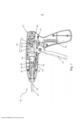
[0009] A Figura 1 é uma vista em seção transversal de um instrumento cirúrgico que incorpora um sistema de bloqueio de atuação;[0009] Figure 1 is a cross-sectional view of a surgical instrument incorporating an actuation locking system;
[0010] A Figura 2 é uma vista em perspectiva de uma modalidade de um sistema de bloqueio de atuação;[0010] Figure 2 is a perspective view of an embodiment of an actuation lock system;
[0011] A Figura 3 é uma vista em perspectiva explodida do sistema de bloqueio de atuação da Figura 2;[0011] Figure 3 is an exploded perspective view of the actuation locking system of Figure 2;
[0012] A Figura 4A é uma vista lateral de uma modalidade de um instrumento cirúrgico que incorpora um sistema de bloqueio de atuação em uma configuração travada;[0012] Figure 4A is a side view of an embodiment of a surgical instrument that incorporates an actuation locking system in a locked configuration;
[0013] A Figura 4B é uma vista lateral do sistema de bloqueio de atuação da Figura 4A em uma configuração destravada;[0013] Figure 4B is a side view of the actuation locking system of Figure 4A in an unlocked configuration;
[0014] A Figura 4C é uma vista em seção transversal de um instrumento cirúrgico incluindo o sistema de bloqueio de atuação da Figura 4A durante sua atuação; e[0014] Figure 4C is a cross-sectional view of a surgical instrument including the actuation locking system of Figure 4A during actuation; It is
[0015] A Figura 5 é uma vista lateral de uma modalidade de um sistema de bloqueio de atuação e de um dispositivo de assistência de força associado a um eixo de transmissão.[0015] Figure 5 is a side view of an embodiment of an actuation blocking system and a force assistance device associated with a transmission shaft.
[0016] Os inventores reconheceram os problemas associados às atuações lentas, parciais, e/ou não intencionais de um instrumento cirúrgico. Por conseguinte, os inventores perceberam as vantagens associadas à provisão de um sistema de bloqueio de atuação que impede a atuação de um instrumento cirúrgico até que uma força limite seja aplicada a um gatilho de atuação. Sem pretender ficar limitado à teoria, em alguns casos, quando um usuário ultrapassa a força limite para atuar o instrumento cirúrgico, isso poderá resultar no fato de o usuário completar naturalmente uma atuação completa do instrumento cirúrgico, simultaneamente evitando uma atuação lenta, parcial, e/ou não intencional, embora outros benefícios possam também resultar de tal instrumento, uma vez que a presente invenção não se limita a esse aspecto.[0016] The inventors recognized the problems associated with slow, partial, and/or unintentional actuations of a surgical instrument. Accordingly, the inventors realized the advantages associated with providing an actuation lock system that prevents actuation of a surgical instrument until a threshold force is applied to an actuation trigger. Without wishing to be bound by theory, in some cases when a user exceeds the force threshold for actuating the surgical instrument, this may result in the user naturally completing a full actuation of the surgical instrument, simultaneously avoiding slow, partial actuation, and /or unintentional, although other benefits may also result from such an instrument, since the present invention is not limited to this aspect.
[0017] Em algumas modalidades, um instrumento cirúrgico inclui uma transmissão de força incluindo um gatilho operacionalmente acoplado a um eixo de transmissão. A transmissão de força transfere a força aplicada ao gatilho por um usuário para o eixo de transmissão, o qual é construído e disposto de modo a desdobrar um fixador a partir de uma extremidade distal do instrumento cirúrgico. O instrumento cirúrgico pode incluir ainda um sistema de bloqueio de atuação associado a qualquer porção da transmissão de força incluindo o gatilho, o eixo de transmissão, e/ou qualquer componente intermediário no sentido de impedir a atuação do instrumento cirúrgico até que uma força limite seja aplicada ao gatilho. Os componentes que podem ser incluídos em uma transmissão de força entre o gatilho e o eixo de transmissão incluem rodas dentadas, engrenagens helicoidais, engrenagens de coroa, parafusos sem fim, sistemas de engrenagens planetárias, correias, interfaces de embreagem, articulações, ou qualquer outro componente adequado capaz de transmitir a força de um componente para outro. No entanto, modalidades nas quais o gatilho é diretamente acoplado ao eixo de transmissão são também contempladas. Além disso, deve-se entender que o eixo de transmissão pode ser configurado de modo a desdobrar qualquer tipo adequado de fixador incluindo ambos os fixadores desdobrados de forma linear ou rotativa. Por conseguinte, deve-se entender que a transmissão de força e o eixo de transmissão podem prover uma força linear ou rotacional a um fixador associado quando o gatilho é atuado. Várias modalidades de sistemas de bloqueio de atuação específicos são descritas em mais detalhes abaixo.[0017] In some embodiments, a surgical instrument includes a power transmission including a trigger operatively coupled to a transmission shaft. Force transmission transfers the force applied to the trigger by a user to the transmission shaft, which is constructed and arranged to deploy a fastener from a distal end of the surgical instrument. The surgical instrument may further include an actuation blocking system associated with any portion of the force transmission including the trigger, the transmission shaft, and/or any intermediate component in order to prevent actuation of the surgical instrument until a limiting force is reached. applied to the trigger. Components that may be included in a power transmission between the trigger and driveshaft include sprockets, helical gears, crown gears, worms, planetary gear systems, belts, clutch interfaces, linkages, or any other suitable component capable of transmitting the force from one component to another. However, embodiments in which the trigger is directly coupled to the transmission shaft are also contemplated. Furthermore, it should be understood that the driveshaft can be configured to deploy any suitable type of fastener including both fasteners linearly or rotatably deployed. Therefore, it should be understood that the power transmission and driveshaft can provide a linear or rotational force to an associated fastener when the trigger is actuated. Various embodiments of specific actuation locking systems are described in more detail below.
[0018] Deve-se entender que a presente invenção não se limita a nenhuma direção de deslocamento do eixo de transmissão em particular. Por exemplo, em algumas modalidades, o eixo de transmissão pode ser deslocado no sentido axial, rotacional, ou em qualquer outro sentido apropriado. Além disso, o sistema de bloqueio de atuação pode ser construído e disposto de qualquer maneira apropriada de modo a facilitar uma contenção do deslocamento do eixo de transmissão em qualquer direção adequada até que uma força maior que ou igual a uma força limite seja aplicada ao gatilho.[0018] It should be understood that the present invention is not limited to any particular transmission shaft displacement direction. For example, in some embodiments, the driveshaft can be displaced in the axial, rotational, or any other appropriate direction. Furthermore, the actuation interlock system may be constructed and arranged in any suitable manner so as to facilitate a restraint of driveshaft displacement in any suitable direction until a force greater than or equal to a limiting force is applied to the trigger. .
[0019] Dependendo da modalidade particular, a força limite necessária para a transição do sistema de bloqueio de atuação de uma configuração travada na qual a atuação do instrumento cirúrgico fica restrita para uma configuração destravada na qual a atuação do instrumento cirúrgico não fica restrita, pode ser maior que ou igual a uma força necessária para atuar o instrumento cirúrgico no sentido de desdobrar um fixador cirúrgico ou realizar outra ação através da atuação do gatilho, tal como cortar, suturar, bem como o desdobramento de grampos para citar algumas. Assim sendo, a aplicação da força limite ao gatilho e a subsequente transição do sistema de bloqueio de atuação da configuração travada para a configuração destravada poderá resultar no fato de um usuário naturalmente completar toda a atuação do gatilho, uma vez que o mesmo já está aplicando uma força maior que a força de atuação. Isso poderá substancialmente impedir o desdobramento lento e/ou incompleto de um fixador cirúrgico quando usado em um instrumento fixador cirúrgico. Embora a força limite possa ser maior que ou igual à força de atuação em algumas modalidades, deve-se entender que, em outras modalidades, a força limite pode ser menor que ou igual à força de atuação, uma vez que a presente invenção não é limitada nesse sentido.[0019] Depending on the particular modality, the threshold force required for the transition of the actuation locking system from a locked configuration in which the actuation of the surgical instrument is restricted to an unlocked configuration in which the actuation of the surgical instrument is not restricted, can be greater than or equal to a force required to actuate the surgical instrument in the sense of deploying a surgical fastener or performing another action through actuation of the trigger, such as cutting, suturing, as well as the deployment of staples to name a few. Therefore, the application of the threshold force to the trigger and the subsequent transition of the actuation interlock system from the locked configuration to the unlocked configuration may result in a user naturally completing all actuation of the trigger, since the trigger is already applying a force greater than the force of action. This can substantially prevent slow and/or incomplete deployment of a surgical fastener when used in a surgical fastener instrument. Although the limit force may be greater than or equal to the actuation force in some embodiments, it should be understood that, in other embodiments, the limit force may be less than or equal to the actuation force, since the present invention is not limited in that sense.
[0020] Em uma modalidade, a atuação de um eixo de transmissão no sentido de desdobrar um fixador cirúrgico envolve a movimentação do eixo de transmissão de uma primeira posição para uma segunda posição. Dependendo do fato de um elemento fixador ser usado de uma forma linear ou rotativa, o deslocamento do eixo de transmissão poderá envolver uma primeira e uma segunda posição rotacional, ou uma primeira posição longitudinal proximal e uma segunda posição longitudinal distal. Em ambos os casos, um sistema de bloqueio de atuação associado a uma transmissão de força incluindo o eixo de transmissão é configurado de modo a restringir o movimento do eixo de transmissão da primeira posição para a segunda posição até que uma força limite seja aplicada a um gatilho operacionalmente acoplado ao eixo de transmissão. Durante seu funcionamento, o sistema de bloqueio de atuação poderá transitar entre uma configuração travada na qual o movimento do eixo de transmissão fica restrito e uma configuração destravada na qual o eixo de transmissão consegue se mover. O sistema de bloqueio de atuação transita da configuração travada para a configuração destravada quando uma força maior que ou igual à força limite é aplicada ao gatilho.[0020] In one embodiment, actuation of a driveshaft in order to deploy a surgical fastener involves moving the driveshaft from a first position to a second position. Depending on whether a fastener element is used in a linear or rotational manner, displacement of the driveshaft may involve a first and second rotational position, or a first proximal longitudinal position and a second distal longitudinal position. In both cases, an actuation locking system associated with a power transmission including the transmission shaft is configured so as to restrict movement of the transmission shaft from the first position to the second position until a limiting force is applied to one trigger operationally coupled to the transmission shaft. During its operation, the actuation locking system can transit between a locked configuration in which the movement of the transmission shaft is restricted and an unlocked configuration in which the transmission shaft is able to move. The actuation lock system transitions from the locked configuration to the unlocked configuration when a force greater than or equal to the threshold force is applied to the trigger.
[0021] Dependendo da modalidade, um sistema de bloqueio de atuação pode se mover entre as configurações travada e destravada de diversas maneiras adequadas. Em uma modalidade, um sistema de bloqueio de atuação pode ser móvel entre a configuração travada e destravada usando uma disposição adequada de duas ou mais superfícies correspondentes dispostas em várias porções da transmissão de força e/ou do instrumento cirúrgico. Por exemplo, em uma modalidade, um sistema de bloqueio de atuação inclui uma primeira superfície direta ou indiretamente acoplada ao eixo de transmissão, e uma segunda superfície direta ou indiretamente acoplada ao manípulo ou a outra porção de um instrumento cirúrgico disposto de modo a seletivamente bloquear o movimento da primeira superfície. Quando o sistema de bloqueio de atuação se encontra na configuração travada, a segunda superfície é acoplada à primeira superfície de tal modo que o deslocamento da primeira superfície, e, por conseguinte, do eixo de transmissão, que é operacionalmente acoplado à primeira superfície, fique restrito. De modo correspondente, quando o sistema de bloqueio de atuação se encontra na configuração destravada, a primeira e a segunda superfícies são desencaixadas, separadas ou de outra forma configuradas de modo a permitir que a primeira superfície e o eixo de transmissão associado se movimentem livremente com relação à segunda superfície. Modalidades específicas de disposições da primeira e da segunda superfícies são descritas em mais detalhe abaixo.[0021] Depending on the modality, an actuation lock system can move between locked and unlocked configurations in several suitable ways. In one embodiment, an actuation locking system can be movable between locked and unlocked configuration using a suitable arrangement of two or more mating surfaces disposed on various portions of the power transmission and/or surgical instrument. For example, in one embodiment, an actuation locking system includes a first surface directly or indirectly coupled to the drive shaft, and a second surface directly or indirectly coupled to the handle or other portion of a surgical instrument arranged to selectively lock the movement of the first surface. When the actuation lock system is in the locked configuration, the second surface is coupled to the first surface in such a way that the displacement of the first surface, and therefore of the driveshaft, which is operatively coupled to the first surface, is restricted. Correspondingly, when the actuation locking system is in the unlocked configuration, the first and second surfaces are disengaged, separated or otherwise configured to allow the first surface and associated driveshaft to move freely with with respect to the second surface. Specific embodiments of first and second surface arrangements are described in more detail below.
[0022] Em certas modalidades, as superfícies de encaixe dispostas de modo a seletivamente impedir a atuação de um instrumento cirúrgico formam uma disposição de came de tal modo que as superfícies sejam impelidas de uma configuração travada para uma configuração destravada quando uma força suficiente é aplicada no sentido de atuar o eixo de transmissão. Tal disposição de came pode ser desejável no sentido de prover um sistema de bloqueio de atuação simples que se movimenta automaticamente da configuração travada para a configuração destravada durante a atuação do eixo de transmissão de uma primeira posição para uma segunda posição. Por exemplo, uma primeira superfície de came associada ao eixo de transmissão pode ser encaixada em uma segunda superfície de came associada a um manípulo de um instrumento cirúrgico quando um sistema de bloqueio de atuação se encontra em uma configuração travada. As superfícies de came podem ser configuradas de tal modo que uma força aplicada no sentido de atuar o eixo de transmissão faça com que a primeira superfície de came aplique uma força à segunda superfície de came que desloca a segunda superfície de came para a configuração destravada, desta forma permitindo um movimento relativo da primeira e da segunda superfícies e, por conseguinte, a atuação do eixo de transmissão.[0022] In certain embodiments, the mating surfaces arranged to selectively prevent actuation of a surgical instrument form a cam arrangement such that the surfaces are urged from a locked configuration to an unlocked configuration when sufficient force is applied in order to actuate the transmission shaft. Such a cam arrangement may be desirable in terms of providing a single acting locking system that automatically moves from the locked configuration to the unlocked configuration during actuation of the driveshaft from a first position to a second position. For example, a first cam surface associated with the driveshaft may engage a second cam surface associated with a handle of a surgical instrument when an actuation locking system is in a locked configuration. The cam surfaces may be configured such that a force applied towards actuating the driveshaft causes the first cam surface to apply a force to the second cam surface which shifts the second cam surface to the unlocked configuration, thus allowing a relative movement of the first and second surfaces and, therefore, the actuation of the transmission shaft.
[0023] As várias modalidades de um sistema de bloqueio de atuação descritas no presente documento não se limitam a nenhum tipo particular de fixador ou instrumento cirúrgico. Por exemplo, um sistema de bloqueio de atuação poderá ser usado com um adesivo, grampo, gancho, pino, ancoragem de tecido, ancoragem óssea, fixadores espirais, parafusos de fixação, ou qualquer outro tipo de fixador que possa se beneficiar do uso de um sistema de bloqueio de atuação de modo a evitar um desdobramento incompleto e/ou não intencional de um fixador. Da mesma forma, o sistema de bloqueio de atuação pode ser usado em qualquer número de procedimentos médicos, incluindo, mas não limitados a, ligação de um tecido ou malha de tecido de reparação a um tecido subjacente, fixação de camadas adjacentes de tecido, fixação de dispositivos e/ou etiquetas de identificação a um gado, além de outras aplicações adequadas envolvendo o desdobramento de um fixador.[0023] The various embodiments of an actuation locking system described herein are not limited to any particular type of fixator or surgical instrument. For example, an actuation lock system could be used with an adhesive, clamp, hook, pin, tissue anchor, bone anchor, spiral fasteners, fixation screws, or any other type of fastener that would benefit from the use of an actuation locking system in order to avoid an incomplete and/or unintentional deployment of a fastener. Likewise, the actuation lock system can be used in any number of medical procedures, including, but not limited to, bonding a tissue or repair tissue mesh to an underlying tissue, securing adjacent layers of tissue, securing of devices and/or identification tags to a cattle, in addition to other suitable applications involving the deployment of a fastener.
[0024] Por motivos de clareza, as modalidades correntemente descritas dizem respeito a dispositivos fixadores laparoscópicos. No entanto, a presente invenção não se limita a esse aspecto. Em vez disso, o sistema de bloqueio de atuação pode ser incorporado em qualquer instrumento cirúrgico atuado. Por exemplo, um sistema de bloqueio de atuação poderá ser empregue em um dispositivo endoscópico, um dispositivo borescópico, um cateter, um instrumento cirúrgico para uso em procedimentos "abertos", instrumentos cirúrgicos incluindo ferramentas de trabalho atuadas, ou qualquer outro instrumento cirúrgico adequado. Em modalidades nas quais o instrumento cirúrgico tem fixadores a serem desdobrados, o instrumento cirúrgico poderá ser construído de modo a permitir ao usuário carregar o instrumento com um ou mais fixadores, poderá ser pré-carregado com um ou mais fixadores, poderá ser seletivamente conectado a uma unidade de carga descartável incluindo um ou mais fixadores pré- carregados, ou poderá ser construído de qualquer maneira apropriada.[0024] For the sake of clarity, the embodiments currently described relate to laparoscopic fixative devices. However, the present invention is not limited to this aspect. Instead, the actuation lock system can be incorporated into any actuated surgical instrument. For example, an actuation lock system may be employed in an endoscopic device, a borescopic device, a catheter, a surgical instrument for use in "open" procedures, surgical instruments including actuated working tools, or any other suitable surgical instrument. In embodiments in which the surgical instrument has fasteners to be deployed, the surgical instrument may be constructed to allow the user to load the instrument with one or more fasteners, may be preloaded with one or more fasteners, may be selectively attached to a disposable loading unit including one or more preloaded fasteners, or it may be constructed in any suitable manner.
[0025] Em seguida, com referência às figuras, são descritas modalidades não limitantes específicas de sistemas de bloqueio de atuação e instrumentos cirúrgicos.[0025] Next, with reference to the figures, specific non-limiting embodiments of actuation locking systems and surgical instruments are described.
[0026] A Figura 1 ilustra um instrumento cirúrgico 10 incluindo um manípulo 12 e um eixo alongado oco 14 que se estende a partir do manípulo para uma extremidade distal do dispositivo a partir do qual elementos de fixação são desdobrados. O instrumento cirúrgico tem uma transmissão de força incluindo um gatilho 16, uma articulação de transmissão 18, uma lançadeira 20, e um eixo de transmissão 24. O gatilho é acoplado à articulação de transmissão, que é operacionalmente acoplada à lançadeira que, por sua vez, é acoplada ao eixo de transmissão. Sendo assim, quando o gatilho é atuado, a articulação de transmissão desloca a lançadeira e seu associado eixo de transmissão em uma direção distal. O eixo de transmissão é configurado e disposto de modo a aplicar uma força a um fixador distalmente localizado, quer direta ou indiretamente, a fim de desdobrar o fixador do instrumento cirúrgico. Quando liberado, o gatilho retorna para a sua posição inicial por meio de uma mola de retorno 22. Esta, por sua vez, retorna a lançadeira e o eixo de transmissão para as suas posições iniciais. Sendo assim, a atuação do gatilho movimenta de maneira alternada a lançadeira e o eixo de transmissão entre as posições distal e proximal. Embora um mecanismo específico de articulação e gatilho seja ilustrado na figura, diferentes gatilhos e articulações de transmissão são previstos. Por exemplo, uma articulação de transmissão pode incorporar engrenagens, articulações de múltiplas barras, ou quaisquer outros mecanismos de transmissão apropriados. Além disso, em algumas modalidades, a articulação de transmissão, ou outro componente de transmissão de força, é construída de modo a prover uma vantagem mecânica para o deslocamento da lançadeira.[0026] Figure 1 illustrates a
[0027] As Figuras 1 a 4 também ilustram uma modalidade de um sistema de bloqueio de atuação 50 que pode ser incluído em um instrumento cirúrgico. Na modalidade ilustrada, o sistema de bloqueio de atuação inclui uma primeira superfície de came 52 disposta sobre a lançadeira 20, e uma segunda superfície de came 54 disposta sobre um braço 56. O braço pode girar em torno de um eixo 60 associado ao manípulo 12. Um elemento de polarização 58 é operacionalmente acoplado ao braço. Na modalidade ilustrada, o elemento de polarização é uma mola de torção. No entanto, outros tipos de elementos de polarização podem ser adequados, tal como descrito abaixo. O elemento de polarização polariza o braço de tal modo que a segunda superfície de came seja impelida em direção à primeira superfície de came. Esta disposição resiste à força aplicada à segunda superfície de came pela primeira superfície de came quando a lançadeira é atuada pelo gatilho 16. Esta resistência ao movimento provê uma força limite que deverá ser ultrapassada a fim de mover o sistema de bloqueio de atuação da configuração travada para a configuração destravada. À medida que a força aplicada ao gatilho aumenta, a força aplicada à segunda superfície de came pela primeira superfície de came também aumentará até que fique igual ou exceda a força de resistência provida pelo elemento de polarização. Assim que a força limite é atingida ou excedida, a primeira superfície de came desloca a segunda superfície de came de modo a permitir o movimento distal da lançadeira e do eixo de transmissão.[0027] Figures 1 to 4 also illustrate an embodiment of an
[0028] Tendo em vista a explicação acima, o sistema de bloqueio de atuação poderá se tornar móvel entre uma configuração travada (Figura 4A) e uma configuração destravada (Figura 4B). Na configuração travada, a primeira e a segunda superfícies de came ficam em contato uma com a outra, deste modo restringindo o movimento distal da lançadeira. Na configuração destravada, a segunda superfície de came se torna excêntrica para fora do percurso de deslocamento da primeira superfície de came em função de uma força de atuação aplicada, deste modo removendo a restrição da lançadeira, e permitindo que a lançadeira e seu associado eixo de transmissão se movimentem no sentido distal a fim de desdobrar um fixador, tal como descrito acima. Embora, na modalidade ilustrada, a primeira e a segunda superfícies sejam dispostas sobre a lançadeira e o braço, respectivamente, outras disposições são previstas. Por exemplo, a primeira e a segunda superfícies de came podem ser dispostas sobre qualquer parte adequada do instrumento cirúrgico, tal como o manípulo, ou sobre qualquer parte da transmissão de força incluindo o eixo de transmissão, a articulação de transmissão ou o gatilho.[0028] In view of the above explanation, the actuation lock system may become mobile between a locked configuration (Figure 4A) and an unlocked configuration (Figure 4B). In the locked configuration, the first and second cam surfaces are in contact with each other, thereby restricting distal movement of the shuttle. In the unlocked configuration, the second cam surface is eccentric out of the travel path of the first cam surface as a function of an applied actuation force, thereby removing the constraint of the shuttle, and allowing the shuttle and its associated camshaft to transmission move distally to deploy a fastener as described above. Although, in the illustrated embodiment, the first and second surfaces are arranged on the shuttle and the arm, respectively, other arrangements are envisaged. For example, the first and second cam surfaces can be disposed on any suitable part of the surgical instrument, such as the handle, or on any part of the power transmission including the transmission shaft, the transmission linkage or the trigger.
[0029] Tal como mais bem ilustrado pela modalidade representada na Figura 4C, as superfícies de came 52 e 54 podem ser configuradas de tal modo que o movimento distal da lançadeira 20 faça com que a primeira superfície de came aplique uma força de came C à segunda superfície de came em uma direção transversal tanto a um eixo longitudinal do eixo de transmissão como também em uma direção de movimento da lançadeira. Esta força desloca a segunda superfície de came para fora do percurso de movimento da primeira superfície de came que coloca o sistema de bloqueio de atuação na configuração destravada. Na modalidade ilustrada, este deslocamento é incorporado pela rotação do braço 56 em torno do eixo 60. Embora uma modalidade tenha sido descrita na qual um braço gira de modo a se mover para a posição desbloqueada, deve-se entender que o braço, ou outro elemento de bloqueio apropriado, poderá também se mover de qualquer forma adequada, inclusive linearmente em resposta à interação das superfícies de came de modo a seletivamente travar a atuação de um instrumento cirúrgico. Por exemplo, uma superfície de came pode ser conectada a uma mola expandida no sentido linear, por exemplo, a uma mola helicoidal, de tal modo que a mesma possa se deslocar transversalmente a um percurso de movimento da correspondente superfície de came em vez de girar para fora desse percurso.[0029] As best illustrated by the embodiment shown in Figure 4C, the cam surfaces 52 and 54 can be configured such that distal movement of the
[0030] Deve-se entender que as superfícies de came usadas em um sistema de bloqueio de atuação podem ter qualquer forma e/ou configuração adequada. Por exemplo, na modalidade ilustrada, a primeira superfície de came é uma superfície curvada côncava formada sobre a lançadeira 20. A curva poderá ter qualquer raio adequado, e o raio poderá ser constante, ou poderá ser diferente ao longo de diferentes pontos da curva de modo a prover um perfil de força de atuação desejada. De modo correspondente, em algumas modalidades, o uso de uma superfície de came de rolamento poderá ser desejável no sentido de prover uma operação mais fácil e/ou mais suave da interface de came. Uma modalidade deste tipo é um cilindro cilíndrico 62, tal como ilustrado nas figuras. Na modalidade ilustrada, o raio do cilindro de modo geral complementa a curvatura da primeira superfície de came. No entanto, são também contempladas as modalidades nas quais as curvaturas, ou outra forma, das superfícies de came não são complementares entre si. O cilindro inclui um furo de passagem no qual um eixo de cilindro 64 é alojado nos furos de passagem 66 formados nas abas 56a que se estendem a partir do braço 56. Em algumas modalidades, o cilindro 62 pode incluir mancais, tais como os mancais de esferas ou mancais de cilindros, a fim de facilitar ainda mais a rotação do cilindro sobre o eixo de cilindro. Em alternativa, um cilindro poderá não incluir um mancal, e no lugar do mesmo poderá apresentar uma folga adequada em torno de um eixo a fim de facilitar a rotação. Em outras modalidades, a segunda superfície de came 54 poderá não girar, e, em vez disso, poderá simplesmente deslizar em relação à primeira superfície de came 52. Além disso, deve-se entender que a primeira e/ou a segunda superfícies de came podem não incluir nenhuma curvatura; por exemplo, as superfícies de came anguladas planas poderão ser adequadas em algumas modalidades.[0030] It should be understood that the cam surfaces used in an actuation lock system may be of any suitable shape and/or configuration. For example, in the illustrated embodiment, the first cam surface is a concave curved surface formed on the
[0031] Tendo descrito os vários componentes de uma transmissão de força e de um sistema de bloqueio de atuação incluídos em um instrumento cirúrgico, o seu método de funcionamento é descrito em mais detalhe com referência às Figuras 4A a 4C. As Figuras 4A e 4C ilustram o sistema de bloqueio de atuação na configuração travada. As superfícies de came 52 e 54 são encaixadas de modo a restringir o movimento distal da lançadeira 20 e seu associado eixo de transmissão 24. O elemento de polarização 58 polariza o braço 56 na direção A impulsionando as superfícies de came em conjunto, tal como acima descrito. Quando uma força é aplicada ao gatilho 16, a rotação do gatilho na direção T aplica uma força à lançadeira 20 por meio da articulação 18 em uma direção distalmente orientada S. A força na direção S, nesse caso, produz uma força de came sobre o braço 56 na direção C distância para fora do percurso de movimento da lançadeira devido à disposição em came das superfícies 52 e 54. Embora um outro componente de força seja também aplicado na direção distal pela disposição em came, este componente da força aplicada não foi ilustrado na figura para motivos de maior clareza. Tal como ilustrado na Figura 4C, a força de came aplicada na direção C à segunda superfície de came se opõe pelo menos a uma porção da força aplicada pelo elemento de polarização na direção rotacional A. Quando a força aplicada ao gatilho ultrapassa uma força limite, a força ao longo da direção C é igual ou maior que a força oposta aplicada pelo elemento de polarização. Quando isso ocorre, a segunda superfície de came é deslocada para fora do percurso da lançadeira e da primeira superfície de came, colocando o sistema de bloqueio de atuação na configuração destravada, tal como mostrado na Figura 4B. Na configuração destravada, a lançadeira 20 e o eixo de transmissão 24 se deslocam no sentido distal ao longo de direção S a fim de desdobrar um fixador cirúrgico, tal como acima descrito.[0031] Having described the various components of a force transmission and actuation lock system included in a surgical instrument, its method of operation is described in more detail with reference to Figures 4A to 4C. Figures 4A and 4C illustrate the actuation locking system in the locked configuration. Cam surfaces 52 and 54 are engaged to restrict distal movement of
[0032] Na modalidade ilustrada, a lançadeira 20 inclui ainda uma superfície 66 sobre a qual a segunda superfície de came 54 percorre quando o sistema de bloqueio de atuação 50 se encontra na configuração destravada. Em termos específicos, a superfície 66 inclui uma inclinação que permite que a força no elemento de polarização 58 diminua à medida que a lançadeira se movimenta no sentido distal. A inclinação da superfície pode ser escolhida de tal modo que a força provida pela mola de retorno 22 seja suficiente para impulsionar o sistema de bloqueio de atuação de volta para a configuração travada depois de um fixador cirúrgico ser desdobrado e uma força ser aplicada por um usuário para o gatilho 16 ser removido. Em algumas modalidades, a superfície pode atuar como uma terceira superfície de came que interage com a segunda superfície de came de modo a prover uma força adicional à lançadeira ou ao eixo de transmissão na direção distalmente orientada S devido à força aplicada pelo elemento de polarização. Uma configuração deste tipo poderá promover ainda mais a completa atuação do instrumento cirúrgico quando o sistema de bloqueio de atuação se movimenta da configuração travada para a configuração destravada. No entanto, deve-se entender que a superfície 66 poderá simplesmente ser plana, poderá não atuar como uma superfície de came, poderá ser curvada, ou ter qualquer outra forma e/ou configuração adequadas para a acomodação da segunda superfície de came à medida que a lançadeira se desloca, uma vez que a presente invenção não é limitada com relação a esse aspecto.[0032] In the illustrated embodiment, the
[0033] Embora a primeira superfície de came tenha sido descrita sobre a lançadeira, a presente invenção de um sistema de bloqueio de atuação não se limita a esse aspecto. Portanto, deve-se entender que a primeira superfície de came pode ser disposta sobre o eixo de transmissão, sobre um componente acoplado ao eixo de transmissão, sobre o gatilho, ou qualquer outra porção adequada do sistema de transmissão de força de tal forma que a atuação do gatilho possa deslocar as superfícies de came umas com relação às outras de modo a seletivamente permitir a atuação do eixo de transmissão assim que uma força limite seja aplicada ao gatilho. Por exemplo, em uma modalidade, uma superfície de came pode ser disposta no sentido coaxial ao eixo de transmissão. Além disso, embora na modalidade ilustrada, o sistema de bloqueio de atuação seja disposto sobre um lado da lançadeira, em outras modalidades, porções de um sistema de bloqueio de atuação poderão ser providas sobre cada um dos lados ou sobre ambos os lados da lançadeira, ou poderão não ser associadas de nenhuma forma à lançadeira.[0033] Although the first cam surface has been described on the shuttle, the present invention of an actuation lock system is not limited to this aspect. Therefore, it is to be understood that the first cam surface may be disposed on the driveshaft, on a component coupled to the driveshaft, on the trigger, or any other suitable portion of the power transmission system such that the trigger actuation can displace the cam surfaces with respect to each other so as to selectively permit actuation of the driveshaft once a threshold force is applied to the trigger. For example, in one embodiment, a cam surface can be disposed coaxial with the driveshaft. Furthermore, although in the illustrated embodiment, the actuation locking system is arranged on one side of the shuttle, in other embodiments, portions of an actuation locking system may be provided on either side or on both sides of the shuttle, or may not be associated with the shuttle in any way.
[0034] Embora o uso de superfícies de came complementares seja ilustrado nas figuras no sentido de mover o sistema de bloqueio de atuação da configuração travada para a configuração destravada, outras disposições e mecanismos são igualmente contemplados. Por exemplo, o sistema de bloqueio de atuação pode incluir uma disposição de cremalheira e pinhão, tal como uma engrenagem de pinhão acoplada ao gatilho, e uma cremalheira formada sobre a superfície disposta de modo a limitar a atuação. A atuação do gatilho pode girar o pinhão e, por sua vez, conduzir um deslocamento da cremalheira e sua superfície associada para a configuração destravada. Em alternativa, articulações acopladas ao gatilho podem ser dispostas de modo a deslocar um mecanismo de trava. Em outro exemplo, uma superfície de came pode ser disposta sobre uma disposição de catraca e lingueta que seletivamente trava o sistema de bloqueio de atuação. A superfície de came pode mover a lingueta sobre um dente ou acessório similar sobre a catraca quando uma força limite é aplicada à superfície de came a fim de mover a catraca e lingueta para uma configuração destravada. Em outros exemplos, um sistema de bloqueio de atuação poderá incluir superfícies complementares que podem ser seletivamente encaixadas de modo a formar um encaixe de interferência, um trinco configurado de modo a se soltar acima de uma força limite predeterminada, ou qualquer outro mecanismo ou dispositivo apropriado, uma vez que a presente invenção não é limitada com relação a esse aspecto. Um mecanismo de bloqueio pode incluir um prendedor, um trinco, fecho, uma trava, um gancho e ilhó, ou qualquer outro dispositivo adequado. Um encaixe de interferência entre superfícies complementares poderá oferecer uma força de resistência ao atrito; essa força de resistência podendo prover a força limite que deve ser ultrapassada no sentido de mover o sistema de bloqueio de atuação para a configuração destravada. Em vista do acima exposto, deve-se entender que um sistema de bloqueio de atuação poderá incluir qualquer disposição de componentes apropriada que restrinja o movimento relativo de dois ou mais componentes ao longo de pelo menos uma direção quando em uma configuração travada. Além disso, um sistema de bloqueio de atuação pode incluir qualquer mecanismo adequado no sentido de mover o sistema de bloqueio de atuação entre as configurações travada e destravada; tais mecanismos podendo ou não ser acoplados a um gatilho de um instrumento cirúrgico.[0034] Although the use of complementary cam surfaces is illustrated in the figures in order to move the actuation locking system from the locked configuration to the unlocked configuration, other arrangements and mechanisms are also contemplated. For example, the actuation locking system may include a rack and pinion arrangement, such as a pinion gear coupled to the trigger, and a rack formed on the surface arranged to limit actuation. Trigger actuation can rotate the pinion and, in turn, drive a displacement of the rack and its associated surface into the unlocked configuration. Alternatively, linkages coupled to the trigger can be arranged to displace a locking mechanism. In another example, a cam surface can be disposed over a ratchet and pawl arrangement that selectively locks the actuation lock system. The cam surface can move the pawl over a tooth or similar fixture on the ratchet when a limiting force is applied to the cam surface to move the ratchet and pawl to an unlocked configuration. In other examples, an actuation locking system may include complementary surfaces that can be selectively mated to form an interference fit, a latch configured to release above a predetermined threshold force, or any other suitable mechanism or device. , as the present invention is not limited in this respect. A locking mechanism may include a catch, latch, clasp, latch, hook and eyelet, or any other suitable device. An interference fit between complementary surfaces may provide a resisting force to friction; this resistance force can provide the limiting force that must be overcome in order to move the actuation locking system to the unlocked configuration. In view of the foregoing, it should be understood that an actuation locking system may include any appropriate component arrangement that restricts the relative movement of two or more components along at least one direction when in a locked configuration. Furthermore, an actuation lock system can include any suitable mechanism for moving the actuation lock system between locked and unlocked configurations; such mechanisms may or may not be coupled to a trigger of a surgical instrument.
[0035] Tal como acima descrito, em algumas modalidades, um sistema de bloqueio de atuação inclui um elemento de polarização acoplado a pelo menos uma superfície de came no sentido de aplicar uma força de trava e seletivamente impedir a atuação do instrumento cirúrgico. No entanto, deve-se entender que as modalidades que não incluem um elemento de polarização poderão também ser contempladas, uma vez que a presente invenção não é limitada com relação a esse aspecto. Por exemplo, uma interface de atrito, um formato em particular e/ou uma configuração de superfícies, ou qualquer outra disposição adequada poderá ser usada no sentido de prover uma força limite de atuação a fim de destravar o sistema de bloqueio de atuação, uma vez que a presente invenção não é limitada quanto a esse aspecto.[0035] As described above, in some embodiments, an actuation locking system includes a bias element coupled to at least one cam surface in order to apply a locking force and selectively prevent actuation of the surgical instrument. However, it is to be understood that embodiments that do not include a polarizing element may also be contemplated, as the present invention is not limited in this regard. For example, a frictional interface, a particular shape and/or surface configuration, or any other suitable arrangement could be used in order to provide an actuation limiting force in order to unlock the actuation locking system, once that the present invention is not limited in this respect.
[0036] Embora uma mola de torção tenha sido ilustrada para o elemento de polarização, o elemento de polarização não se limita apenas a uma mola de torção. Por exemplo, o elemento de polarização poderá incluir, mas não se limita a, uma mola espiral, uma mola de lâmina, uma mola de carga automática, uma mola a gás, uma haste elástica, ou qualquer outra estrutura ou dispositivo adequado capaz de prover uma força no sentido de resistir ao deslocamento da segunda superfície de came e prover uma força limite de modo a seletivamente destravar o sistema de bloqueio de atuação. Além disso, embora um elemento de polarização separado tenha sido ilustrado, um elemento de polarização poderá também ser integralmente moldado a uma porção do sistema de bloqueio de atuação. Por exemplo, um acessório integralmente moldado, tal como um braço flexível, uma aba, ou outro recurso poderá funcionar tanto como uma superfície de came ou como um elemento de polarização, uma vez que a presente invenção não é limitada com relação a esse aspecto.[0036] Although a torsion spring has been illustrated for the bias element, the bias element is not limited to just a torsion spring. For example, the biasing element may include, but is not limited to, a coil spring, a leaf spring, a self-loading spring, a gas spring, an elastic rod, or any other suitable structure or device capable of providing a force in the sense of resisting displacement of the second cam surface and providing a limiting force in order to selectively unlock the actuation locking system. Furthermore, although a separate bias element has been illustrated, a bias element could also be integrally molded to a portion of the actuation lock system. For example, an integrally molded accessory such as a flexible arm, a flap, or other feature could function as either a cam surface or a bias element, as the present invention is not limited in that regard.
[0037] Em certas modalidades, um sistema de bloqueio de atuação poderá ser particularmente útil quando incorporado a um instrumento cirúrgico com um dispositivo de assistência de força configurado de modo a auxiliar no desdobramento de um fixador cirúrgico. O dispositivo de assistência de força pode ser configurado de modo a prover um impulso de curta duração ao eixo de transmissão ao bater no eixo de transmissão com uma massa móvel, tal como descrito em mais detalhe abaixo. Sem a pretensão de ficar limitada à teoria, a provisão de um impulso de curta duração poderá resultar na aplicação de uma força maior a um prendedor durante o seu desdobramento, o que poderá melhorar a penetração de um tecido protético e reduzir a força manual necessária emitida por parte de um usuário. Dependendo da modalidade em particular, um dispositivo de assistência de força poderá ser atuado quando uma força limite é aplicada ao gatilho, e um sistema de bloqueio de atuação se movimenta de uma configuração travada para uma configuração destravada.[0037] In certain embodiments, an actuation locking system may be particularly useful when incorporated into a surgical instrument with a force assist device configured to assist in the deployment of a surgical fastener. The power assist device can be configured to provide a short-term thrust to the driveshaft by hitting the driveshaft with a moving mass, as described in more detail below. Without intending to be bound by theory, the provision of a short-duration impulse may result in greater force being applied to a fastener during deployment, which may improve penetration of a prosthetic tissue and reduce the required manual force emitted. by a user. Depending on the particular embodiment, a force assist device may be actuated when a limit force is applied to the trigger, and an actuation interlock system moves from a locked configuration to an unlocked configuration.
[0038] Uma modalidade de um dispositivo de assistência de força é ilustrada nas Figuras 1 e 5. O dispositivo de assistência de força ilustrado inclui um elemento de armazenamento de energia 28, um percussor 30, e uma superfície de impacto 32. Na modalidade ilustrada, a superfície de impacto 32 é um colar acoplado ao eixo de transmissão 24, embora outras disposições sejam também contempladas. O dispositivo de assistência de força inclui ainda um alojamento de elemento de armazenamento de energia 26 e um mecanismo de trava 34. Tal como ilustrado nas figuras, o elemento de armazenamento de energia é uma mola espiral. No entanto, o elemento de armazenamento de energia pode ser qualquer componente adequado capaz de armazenar e liberar energia, incluindo molas espirais, molas de ar, molas a gás, hastes ou tiras elásticas, molas de carga automática, molas de lâmina, barras de torção, ou molas de torção. Além disso, o alojamento de elemento de armazenamento de energia é operacionalmente acoplado à lançadeira 20. O elemento de armazenamento de energia é disposto no sentido coaxial sobre o eixo de transmissão 24 e parcialmente disposto dentro de um volume interno do alojamento de elemento de armazenamento de energia. No entanto, outras configurações incluindo aquelas nas quais o elemento de armazenamento de energia é disposto fora do alojamento são igualmente contempladas. O elemento de armazenamento de energia e o alojamento de elemento de armazenagem de energia são configurados de tal forma que o deslocamento do eixo de transmissão no sentido distal desloque o alojamento de elemento de armazenamento de energia e também a associada extremidade proximal do elemento de armazenamento de energia no sentido distal. Uma vez que o elemento de armazenamento de energia 28 se situa entre o percussor e o alojamento de elemento de armazenamento de energia, embora o percussor fique travado no lugar pelo mecanismo de trava 34, esse movimento irá comprimir o elemento de armazenamento de energia.[0038] One embodiment of a force assist device is illustrated in Figures 1 and 5. The illustrated force assist device includes an
[0039] À medida que o eixo de transmissão continua a se deslocar na direção distal, o mecanismo de trava 34 se movimenta para a posição destravada através do uso de uma primeira superfície de came de assistência de força 38 situada sobre o alojamento de elemento de armazenamento de energia 26 e de uma segunda superfície de came de assistência de força 36 localizada sobre o mecanismo de trava. À medida que o alojamento de elemento de armazenamento de energia 26 se desloca na direção distal, a primeira superfície de came de assistência de força entra em contato com a segunda superfície de came de assistência de força e desloca o mecanismo de trava para fora a fim de libertar o percussor 30 e o elemento de armazenamento de energia 28. O elemento de armazenamento de energia liberado acelera o percussor no sentido distal em direção à superfície de impacto 32 a fim de comunicar um impulso ao eixo de transmissão 24 e desdobrar um fixador associado. Ao ser atingido, o eixo de transmissão se acelera em uma direção distal no sentido de desdobrar um fixador.[0039] As the driveshaft continues to travel in the distal direction, the
[0040] Embora um dispositivo de assistência de força em particular seja descrito no presente documento, outras modalidades, disposições e/ou configurações adequadas de um dispositivo de assistência de força para uso em um instrumento cirúrgico são igualmente descritas no Pedido de Patente dos Estados Unidos N. 13/804.043, depositado em 14 de março de 2013, publicado como Documento US 2014/0276963, cuja apresentação é incorporada ao presente documento a título de referência em sua totalidade.[0040] While a particular force-assisting device is described herein, other suitable embodiments, arrangements, and/or configurations of a force-assisting device for use in a surgical instrument are likewise described in the United States Patent Application N. 13/804.043, filed on March 14, 2013, published as Document US 2014/0276963, the presentation of which is incorporated into this document by way of reference in its entirety.
[0041] Embora os presentes ensinamentos tenham sido descritos em conjunto com várias modalidades e exemplos, não se pretende que os presentes ensinamentos fiquem limitados a essas modalidades ou exemplos. Pelo contrário, os presentes ensinamentos deverão abranger várias alternativas, modificações e equivalentes, tal como será apreciado pelos versados na técnica. Por conseguinte, a descrição acima e os desenhos em anexo são apresentados tão somente a título de exemplo.[0041] While the present teachings have been described in conjunction with various embodiments and examples, it is not intended that the present teachings be limited to those embodiments or examples. Rather, the present teachings should encompass various alternatives, modifications and equivalents, as will be appreciated by those skilled in the art. Therefore, the above description and the attached drawings are presented by way of example only.
Claims (12)
Applications Claiming Priority (3)
| Application Number | Priority Date | Filing Date | Title |
|---|---|---|---|
| US14/711,324 US10159471B2 (en) | 2015-05-13 | 2015-05-13 | Actuation lockout for a surgical instrument |
| US14/711,324 | 2015-05-13 | ||
| PCT/US2016/028585 WO2016182706A1 (en) | 2015-05-13 | 2016-04-21 | Actuation lockout for a surgical instrument |
Publications (2)
| Publication Number | Publication Date |
|---|---|
| BR112017023623A2 BR112017023623A2 (en) | 2018-07-17 |
| BR112017023623B1 true BR112017023623B1 (en) | 2023-05-02 |
Family
ID=55854830
Family Applications (1)
| Application Number | Title | Priority Date | Filing Date |
|---|---|---|---|
| BR112017023623-0A BR112017023623B1 (en) | 2015-05-13 | 2016-04-21 | SURGICAL INSTRUMENT |
Country Status (7)
| Country | Link |
|---|---|
| US (4) | US10159471B2 (en) |
| EP (1) | EP3294148A1 (en) |
| JP (3) | JP7032137B2 (en) |
| CN (2) | CN111513774A (en) |
| AU (3) | AU2016261059B2 (en) |
| BR (1) | BR112017023623B1 (en) |
| WO (1) | WO2016182706A1 (en) |
Families Citing this family (5)
| Publication number | Priority date | Publication date | Assignee | Title |
|---|---|---|---|---|
| US10159471B2 (en) * | 2015-05-13 | 2018-12-25 | C.R. Bard, Inc. | Actuation lockout for a surgical instrument |
| US20180271526A1 (en) * | 2017-03-22 | 2018-09-27 | Covidien Lp | Endoscopic surgical clip applier |
| EP3703602A4 (en) * | 2017-11-02 | 2021-01-13 | Intuitive Surgical Operations, Inc. | Systems and methods for end effector position set point correction |
| WO2019128688A1 (en) * | 2017-12-26 | 2019-07-04 | 苏州天臣国际医疗科技有限公司 | Handle assembly and stapler comprising same |
| WO2020214657A1 (en) * | 2019-04-17 | 2020-10-22 | Davol Inc. | Surgical instrument with fastener preload lock-out |
Family Cites Families (51)
| Publication number | Priority date | Publication date | Assignee | Title |
|---|---|---|---|---|
| US5827263A (en) | 1994-07-21 | 1998-10-27 | Genzyme Corporation | Surgical instrument handle |
| US5762255A (en) * | 1996-02-20 | 1998-06-09 | Richard-Allan Medical Industries, Inc. | Surgical instrument with improvement safety lockout mechanisms |
| US5665105A (en) | 1996-03-20 | 1997-09-09 | Snowden Pencer/Genzyme Corporation | Radially adjustable surgical instrument for heart surgery |
| DE19755407B4 (en) * | 1997-12-12 | 2007-12-13 | Hilti Ag | setting tool |
| US6457625B1 (en) | 1998-02-17 | 2002-10-01 | Bionx Implants, Oy | Device for installing a tissue fastener |
| US6042601A (en) | 1998-03-18 | 2000-03-28 | United States Surgical Corporation | Apparatus for vascular hole closure |
| US6425900B1 (en) | 2000-10-19 | 2002-07-30 | Ethicon Endo-Surgery | Method for attaching hernia mesh |
| US7485124B2 (en) * | 2000-10-19 | 2009-02-03 | Ethicon Endo-Surgery, Inc. | Surgical instrument having a fastener delivery mechanism |
| ES2632965T3 (en) * | 2002-10-04 | 2017-09-18 | Covidien Lp | Pneumatically Motorized Surgical Stapling Device |
| JP4086621B2 (en) | 2002-10-28 | 2008-05-14 | 株式会社トップ | Surgical instrument handle structure |
| JP2006507868A (en) * | 2002-11-27 | 2006-03-09 | コーニンクレッカ フィリップス エレクトロニクス エヌ ヴィ | Method and apparatus for automatically self-aligning a bed to a magnetic resonance imaging scanner |
| US8926637B2 (en) | 2003-06-13 | 2015-01-06 | Covidien Lp | Multiple member interconnect for surgical instrument and absorbable screw fastener |
| US7143926B2 (en) * | 2005-02-07 | 2006-12-05 | Ethicon Endo-Surgery, Inc. | Surgical stapling instrument incorporating a multi-stroke firing mechanism with return spring rotary manual retraction system |
| TWI369970B (en) * | 2004-10-20 | 2012-08-11 | Beaver Visitec Int Us Inc | Surgical knife safety handle having user operable lock |
| US7886953B2 (en) | 2005-08-18 | 2011-02-15 | Ethicon Endo-Surgery, Inc. | Fired device lockout for a curved cutter stapler with a free moving trigger |
| US7771440B2 (en) | 2005-08-18 | 2010-08-10 | Ethicon Endo-Surgery, Inc. | Method and apparatus for endoscopically performing gastric reduction surgery in a single pass |
| US7540400B2 (en) * | 2006-01-06 | 2009-06-02 | Staples The Office Superstore, Llc | Stapler having a moveable strike plate with lockout mechanism |
| US7740159B2 (en) * | 2006-08-02 | 2010-06-22 | Ethicon Endo-Surgery, Inc. | Pneumatically powered surgical cutting and fastening instrument with a variable control of the actuating rate of firing with mechanical power assist |
| US8794496B2 (en) | 2006-09-11 | 2014-08-05 | Covidien Lp | Rotating knob locking mechanism for surgical stapling device |
| US7967178B2 (en) | 2006-10-06 | 2011-06-28 | Tyco Healthcare Group Lp | Grasping jaw mechanism |
| US7569063B2 (en) * | 2006-10-13 | 2009-08-04 | Sofradim Production Sas | Instrument for storing and dispensing a surgical fastener |
| DE102006035460A1 (en) * | 2006-11-27 | 2008-05-29 | Hilti Ag | Hand-guided tacker |
| US7950562B2 (en) | 2007-01-31 | 2011-05-31 | Tyco Healthcare Group Lp | Surgical instrument with replaceable loading unit |
| US7950560B2 (en) * | 2007-04-13 | 2011-05-31 | Tyco Healthcare Group Lp | Powered surgical instrument |
| US8800837B2 (en) * | 2007-04-13 | 2014-08-12 | Covidien Lp | Powered surgical instrument |
| US7931660B2 (en) | 2007-05-10 | 2011-04-26 | Tyco Healthcare Group Lp | Powered tacker instrument |
| US7441685B1 (en) | 2007-06-22 | 2008-10-28 | Ethicon Endo-Surgery, Inc. | Surgical stapling instrument with a return mechanism |
| US8012170B2 (en) * | 2009-04-27 | 2011-09-06 | Tyco Healthcare Group Lp | Device and method for controlling compression of tissue |
| FR2924917B1 (en) * | 2007-12-13 | 2011-02-11 | Microval | APPARATUS FOR INSTALLING SUTURE SPIERS RESULTING FROM A SHAPE MEMORY METAL WIRE. |
| US8439898B2 (en) | 2008-06-17 | 2013-05-14 | Usgi Medical, Inc. | Endoscopic tissue anchor deployment |
| US7857186B2 (en) | 2008-09-19 | 2010-12-28 | Ethicon Endo-Surgery, Inc. | Surgical stapler having an intermediate closing position |
| GB2466180B (en) * | 2008-12-05 | 2013-07-10 | Surgical Innovations Ltd | Surgical instrument, handle for a surgical instrument and surgical instrument system |
| US8353436B2 (en) | 2009-05-06 | 2013-01-15 | Covidien Lp | Pin locking mechanism for a surgical instrument |
| US8920439B2 (en) * | 2009-05-12 | 2014-12-30 | Ethicon, Inc. | Applicator instruments having curved and articulating shafts for deploying surgical fasteners and methods therefor |
| US9517027B2 (en) | 2009-07-10 | 2016-12-13 | Facet Techonologies, Llc | Advancement mechanism for cartridge-based devices |
| IN2012DN02987A (en) * | 2009-10-09 | 2015-07-31 | Ethicon Endo Surgery Inc | |
| US8683895B2 (en) * | 2010-02-23 | 2014-04-01 | Kensey Nash Corporation | Single revolution snap action drive for surgical fasteners |
| EP2704652A4 (en) | 2011-05-03 | 2015-06-10 | Biodynamics Llc | Bone tack driver |
| US9078648B2 (en) | 2011-11-07 | 2015-07-14 | C.R. Bard, Inc. | Instruments for delivering transfascial sutures and methods of transfascial suturing |
| SG11201402794YA (en) | 2011-12-02 | 2014-11-27 | Bioceptive Inc | Methods and apparatus for inserting a device or pharmaceutical into a uterus |
| US9198704B2 (en) * | 2012-07-18 | 2015-12-01 | Jmea Corporation | Impact and drive system for prosthesis deployment device |
| US9386984B2 (en) * | 2013-02-08 | 2016-07-12 | Ethicon Endo-Surgery, Llc | Staple cartridge comprising a releasable cover |
| US9717497B2 (en) | 2013-02-28 | 2017-08-01 | Ethicon Llc | Lockout feature for movable cutting member of surgical instrument |
| US9649109B2 (en) | 2013-03-14 | 2017-05-16 | C.R. Bard, Inc. | Surgical instrument with an actuation lockout |
| US20140263541A1 (en) * | 2013-03-14 | 2014-09-18 | Ethicon Endo-Surgery, Inc. | Articulatable surgical instrument comprising an articulation lock |
| US9364235B2 (en) * | 2013-03-14 | 2016-06-14 | C.R. Bard, Inc. | Power assist device for a surgical instrument |
| EP2845549B1 (en) * | 2013-09-10 | 2016-08-31 | Erbe Elektromedizin GmbH | Surgical instrument with improved actuating mechanism |
| US9526498B2 (en) * | 2013-09-17 | 2016-12-27 | Covidien Lp | Surgical device with a trigger lockout mechanism device |
| CN203970461U (en) * | 2014-03-31 | 2014-12-03 | 瑞奇外科器械(中国)有限公司 | A kind of surgical operating instrument safety and surgical operating instrument |
| WO2016000255A1 (en) | 2014-07-04 | 2016-01-07 | Covidien Lp | Surgical fastener applying apparatus and methods for endoscopic procedures |
| US10159471B2 (en) | 2015-05-13 | 2018-12-25 | C.R. Bard, Inc. | Actuation lockout for a surgical instrument |
-
2015
- 2015-05-13 US US14/711,324 patent/US10159471B2/en active Active
-
2016
- 2016-04-21 JP JP2017556801A patent/JP7032137B2/en active Active
- 2016-04-21 CN CN202010311409.0A patent/CN111513774A/en active Pending
- 2016-04-21 EP EP16718984.4A patent/EP3294148A1/en active Pending
- 2016-04-21 WO PCT/US2016/028585 patent/WO2016182706A1/en active Application Filing
- 2016-04-21 BR BR112017023623-0A patent/BR112017023623B1/en active IP Right Grant
- 2016-04-21 CN CN201680027043.6A patent/CN107580476B/en active Active
- 2016-04-21 AU AU2016261059A patent/AU2016261059B2/en active Active
-
2018
- 2018-11-05 US US16/180,435 patent/US10772613B2/en active Active
-
2020
- 2020-08-13 US US16/992,290 patent/US11389143B2/en active Active
- 2020-09-24 AU AU2020239733A patent/AU2020239733B2/en active Active
-
2021
- 2021-01-21 JP JP2021007976A patent/JP7208275B2/en active Active
-
2022
- 2022-06-24 US US17/848,497 patent/US20220313228A1/en active Pending
- 2022-10-17 JP JP2022166227A patent/JP7455175B2/en active Active
- 2022-11-24 AU AU2022275460A patent/AU2022275460B2/en active Active
Also Published As
| Publication number | Publication date |
|---|---|
| AU2022275460A1 (en) | 2023-01-05 |
| JP2021058797A (en) | 2021-04-15 |
| US11389143B2 (en) | 2022-07-19 |
| JP7208275B2 (en) | 2023-01-18 |
| WO2016182706A1 (en) | 2016-11-17 |
| EP3294148A1 (en) | 2018-03-21 |
| JP2022183248A (en) | 2022-12-08 |
| US20200367869A1 (en) | 2020-11-26 |
| AU2022275460B2 (en) | 2024-02-15 |
| JP7455175B2 (en) | 2024-03-25 |
| WO2016182706A8 (en) | 2017-01-26 |
| BR112017023623A2 (en) | 2018-07-17 |
| US10159471B2 (en) | 2018-12-25 |
| US20160331462A1 (en) | 2016-11-17 |
| JP2018515199A (en) | 2018-06-14 |
| AU2020239733B2 (en) | 2022-09-01 |
| US10772613B2 (en) | 2020-09-15 |
| US20190069888A1 (en) | 2019-03-07 |
| CN111513774A (en) | 2020-08-11 |
| US20220313228A1 (en) | 2022-10-06 |
| CN107580476A (en) | 2018-01-12 |
| JP7032137B2 (en) | 2022-03-08 |
| AU2016261059A8 (en) | 2017-12-21 |
| AU2020239733A1 (en) | 2020-10-15 |
| AU2016261059A1 (en) | 2017-11-30 |
| CN107580476B (en) | 2020-05-15 |
| AU2016261059B2 (en) | 2020-07-02 |
Similar Documents
| Publication | Publication Date | Title |
|---|---|---|
| BR112017023623B1 (en) | SURGICAL INSTRUMENT | |
| JP6662924B2 (en) | Tissue anchor and tissue anchor | |
| ES2675923T3 (en) | Surgical intervention instrument and drive device | |
| JP6194096B2 (en) | Surgical instrument with actuated lockout | |
| CN104414737B (en) | Articulating equipment for endoscopic procedure | |
| RU2461363C2 (en) | Articulation curved cutoff stapler | |
| JP6134432B2 (en) | Power assist device for surgical instruments | |
| ES2788640T3 (en) | Laparoscopic Suture System | |
| BRPI0600256B1 (en) | SURGICAL INSTRUMENT | |
| KR20160027054A (en) | Articulating apparatus for endoscopic procedures | |
| ES2895727T3 (en) | Activation lock for a surgical instrument | |
| BR122022019943B1 (en) | SURGICAL INSTRUMENT WITH ACTUATION LOCK |
Legal Events
| Date | Code | Title | Description |
|---|---|---|---|
| B06U | Preliminary requirement: requests with searches performed by other patent offices: procedure suspended [chapter 6.21 patent gazette] | ||
| B07A | Application suspended after technical examination (opinion) [chapter 7.1 patent gazette] | ||
| B09A | Decision: intention to grant [chapter 9.1 patent gazette] | ||
| B16A | Patent or certificate of addition of invention granted [chapter 16.1 patent gazette] |
Free format text: PRAZO DE VALIDADE: 20 (VINTE) ANOS CONTADOS A PARTIR DE 21/04/2016, OBSERVADAS AS CONDICOES LEGAIS |