BR112016020884B1 - TRAFFIC SIGN DETECTION DEVICE AND TRAFFIC SIGN DETECTION METHOD - Google Patents
TRAFFIC SIGN DETECTION DEVICE AND TRAFFIC SIGN DETECTION METHOD Download PDFInfo
- Publication number
- BR112016020884B1 BR112016020884B1 BR112016020884-6A BR112016020884A BR112016020884B1 BR 112016020884 B1 BR112016020884 B1 BR 112016020884B1 BR 112016020884 A BR112016020884 A BR 112016020884A BR 112016020884 B1 BR112016020884 B1 BR 112016020884B1
- Authority
- BR
- Brazil
- Prior art keywords
- traffic signal
- traffic
- pixel
- phase
- vehicle
- Prior art date
Links
Images


Classifications
-
- G—PHYSICS
- G06—COMPUTING; CALCULATING OR COUNTING
- G06V—IMAGE OR VIDEO RECOGNITION OR UNDERSTANDING
- G06V20/00—Scenes; Scene-specific elements
- G06V20/50—Context or environment of the image
- G06V20/56—Context or environment of the image exterior to a vehicle by using sensors mounted on the vehicle
- G06V20/58—Recognition of moving objects or obstacles, e.g. vehicles or pedestrians; Recognition of traffic objects, e.g. traffic signs, traffic lights or roads
- G06V20/584—Recognition of moving objects or obstacles, e.g. vehicles or pedestrians; Recognition of traffic objects, e.g. traffic signs, traffic lights or roads of vehicle lights or traffic lights
-
- B—PERFORMING OPERATIONS; TRANSPORTING
- B60—VEHICLES IN GENERAL
- B60W—CONJOINT CONTROL OF VEHICLE SUB-UNITS OF DIFFERENT TYPE OR DIFFERENT FUNCTION; CONTROL SYSTEMS SPECIALLY ADAPTED FOR HYBRID VEHICLES; ROAD VEHICLE DRIVE CONTROL SYSTEMS FOR PURPOSES NOT RELATED TO THE CONTROL OF A PARTICULAR SUB-UNIT
- B60W10/00—Conjoint control of vehicle sub-units of different type or different function
-
- G—PHYSICS
- G08—SIGNALLING
- G08G—TRAFFIC CONTROL SYSTEMS
- G08G1/00—Traffic control systems for road vehicles
- G08G1/16—Anti-collision systems
Landscapes
- Engineering & Computer Science (AREA)
- Physics & Mathematics (AREA)
- General Physics & Mathematics (AREA)
- Multimedia (AREA)
- Theoretical Computer Science (AREA)
- Traffic Control Systems (AREA)
- Image Processing (AREA)
- Image Analysis (AREA)
Abstract
DISPOSITIVO DE DETECÇÃO DE SINAL DE TRÂNSITO E MÉTODO DE DETECÇÃO DE SINAL DE TRÂNSITO. Um dispositivo de detecção de sinal de trânsito inclui uma unidade de captura de imagem (11) configurada de modo a repetidamente capturar imagens em uma direção de movimento de um veículo de modo a obter uma série de múltiplas imagens (28), e uma unidade de detecção de sinal de trânsito (12) configurada de modo a detectar sinais de trânsito (32, 33) a partir das imagens (28). A unidade de detecção de sinal de trânsito (12) detecta as informações de fase de um sistema de energia elétrica usado em uma área em torno do veículo incluindo os sinais de trânsito a partir de um ciclo de uma variação de luminância na série de múltiplas imagens e extrai, a partir das imagens (28), um pixel sincronizado com uma luminância que varia em sincronia com um ciclo de corrente alternada da potência elétrica suprida para o sinal de trânsito (32, 33) usando as informações de fase do sistema de energia elétrica. O dispositivo de detecção de sinal de trânsito analisa, a partir do pixel sincronizado, se o sinal de trânsito permanece presente ou não.TRAFFIC SIGN DETECTION DEVICE AND TRAFFIC SIGN DETECTION METHOD. A traffic sign detection device includes an image capture unit (11) configured to repeatedly capture images in a direction of movement of a vehicle so as to obtain a series of multiple images (28), and a traffic sign detection (12) configured to detect traffic signs (32, 33) from the images (28). The traffic signal detection unit (12) detects the phase information of an electrical power system used in an area around the vehicle including the traffic signals from a cycle of a luminance variation in the series of multiple images. and extracts, from the images (28), a pixel synchronized with a luminance that varies in sync with an alternating current cycle of the electrical power supplied to the traffic signal (32, 33) using the phase information of the power system electric. The traffic signal detection device analyzes from the synchronized pixel whether the traffic signal remains present or not.
Description
[001] A presente invenção refere-se a um dispositivo de detecção de sinal de trânsito e a um método de detecção de sinal de trânsito.[001] The present invention relates to a traffic signal detection device and a traffic signal detection method.
[002] Até o momento, é conhecido um dispositivo de detecção de sinal de trânsito para a detecção de um sinal de trânsito a partir de uma imagem capturada por uma câmera (vide Literatura de Patente 1). De acordo com a Literatura de Patente 1, uma parte que indica uma cor de uma lâmpada de controle é extraída da imagem, a circularidade da mesma indicando quão próximo a um círculo perfeito a parte extraída pode ser calculada, e uma parte tendo uma circularidade maior é detectada como uma candidata para a lâmpada de controle. LISTA DE CITAÇÕES Literaturas de Patente Literatura de Patente 1: Publicação do Pedido de Patente do Japão N. 2005-301518.[002] So far, a traffic sign detection device is known for detecting a traffic sign from an image captured by a camera (see Patent Literature 1). According to Patent Literature 1, a part indicating a color of a control lamp is extracted from the image, the circularity of the image indicating how close to a perfect circle the extracted part can be calculated, and a part having a greater circularity. is detected as a candidate for the control lamp. LIST OF QUOTES Patent Literature Patent Literature 1: Japan Patent Application Publication No. 2005-301518.
[003] Para ser detectada como uma candidata para uma lâmpada de controle, a parte extraída precisa ter um tamanho de imagem grande o suficiente para que a sua circularidade possa ser determinada. Por este aspecto, a técnica da Literatura de Patente 1 tem dificuldade em apresentar a detecção precisa de um sinal de trânsito distante, cujo tamanho de imagem seja demasiadamente pequeno para determinar a sua circularidade.[003] To be detected as a candidate for a control lamp, the extracted part needs to have an image size large enough so that its circularity can be determined. In this regard, the Patent Literature 1 technique has difficulty in providing accurate detection of a distant traffic signal whose image size is too small to determine its circularity.
[004] A presente invenção foi produzida tendo em vista o problema acima, e um objeto da mesma é prover um dispositivo de detecção de sinal de trânsito e um método de detecção de sinal de trânsito capazes de detectar até mesmo um sinal de trânsito distante com alta precisão.[004] The present invention has been produced in view of the above problem, and an object thereof is to provide a traffic signal detection device and a traffic signal detection method capable of detecting even a distant traffic signal with high precision.
[005] Um dispositivo de detecção de sinal de trânsito de acordo com um as-pecto da presente invenção inclui uma unidade de captura de imagem configurada de modo a repetidamente capturar uma imagem do entorno de um veículo de modo a obter uma série de múltiplas imagens e uma unidade de detecção de sinal de trânsito configurada de modo a detectar um sinal de trânsito a partir das imagens. A unidade de detecção de sinal de trânsito detecta as informações de fase de um sistema de energia elétrica usado em uma área em torno do veículo incluindo o sinal de trânsito a partir de um ciclo de variação de luminância na série de múltiplas imagens e extrai, a partir das imagens, um pixel sincronizado com uma luminância que varia em sincronia com um ciclo de corrente alternada da potência elétrica suprida para o sinal de trânsito usando as informações de fase do sistema de energia elétrica. O dis-positivo de detecção de sinal de trânsito analisa, a partir do pixel sincronizado, se o sinal de trânsito permanece presente ou não.[005] A traffic sign detection device according to an aspect of the present invention includes an image capture unit configured to repeatedly capture an image of the surroundings of a vehicle in order to obtain a series of multiple images. and a traffic signal detection unit configured to detect a traffic signal from the images. The traffic signal detection unit detects the phase information of an electrical power system used in an area around the vehicle including the traffic signal from a cycle of luminance variation in the series of multiple images and extracts, the from the images, a pixel synchronized with a luminance that varies in sync with an alternating current cycle of the electrical power supplied to the traffic signal using the phase information of the electrical power system. The traffic signal detection device analyzes from the synchronized pixel whether the traffic signal remains present or not.
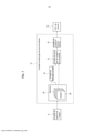
[006] A Figura 1 é um diagrama de blocos ilustrando uma configuração geral de um dispositivo de detecção de sinal de trânsito de acordo com uma modalidade da presente invenção;[006] Figure 1 is a block diagram illustrating a general configuration of a traffic signal detection device according to an embodiment of the present invention;
[007] A Figura 2 é um diagrama de blocos ilustrando uma configuração deta-lhada da unidade de geração de imagens sincronizadas 15 ilustrada na Figura 1;[007] Figure 2 is a block diagram illustrating a detailed configuration of the synchronized
[008] A Figura 3(a) é um gráfico ilustrando uma diferença na faixa de varia-ção de luminância dependendo da distância com relação a um veículo, e a Figura 3(b) é um exemplo de uma imagem de câmera ilustrando um poste de iluminação 31a, uma máquina automática de venda 31b, e um letreiro luminoso 31c como exemplos de outros tipos de lâmpadas elétricas localizadas nas proximidades do veículo, e ilustrando sinais de trânsito 32 e 33 distantes do veículo;[008] Figure 3(a) is a graph illustrating a difference in the range of luminance variation depending on the distance from a vehicle, and Figure 3(b) is an example of a camera image illustrating a
[009] A Figura 4 é um diagrama de blocos ilustrando uma modificação de uma unidade de detecção de fase 19;[009] Figure 4 is a block diagram illustrating a modification of a 19-phase detection unit;
[010] A Figura 5 é um diagrama ilustrando um exemplo de uma imagem de câmera capturada quando o veículo está se deslocando em um túnel;[010] Figure 5 is a diagram illustrating an example of a camera image captured when the vehicle is traveling in a tunnel;
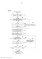
[011] A Figura 6 é um fluxograma ilustrando um exemplo de um método de detecção de sinal de trânsito usando o dispositivo de detecção de sinal de trânsito ilustrado na Figura 1;[011] Figure 6 is a flowchart illustrating an example of a traffic sign detection method using the traffic sign detection device illustrated in Figure 1;
[012] A Figura 7(a) é um diagrama indicando o tamanho necessário de um grupo de pixels 53a para detectar uma candidata para uma lâmpada de controle a partir da sua circularidade, e a Figura 7(b) é um diagrama indicando o número de pixels sincronizados 53b que podem ser detectados na modalidade;[012] Figure 7(a) is a diagram indicating the necessary size of a group of
[013] A Figura 8 ilustra uma diferença nos valores de correlação entre o momento em que uma fase de um sinal de referência é sincronizada e não sincroni-zada, sendo que a Figura 8(a) ilustra um estado no qual a fase do sinal de referência é sincronizada com a fase de uma potência elétrica, e a Figura 8(b) ilustra um estado no qual a fase do sinal de referência é invertida com relação à fase da potência elé-trica.[013] Figure 8 illustrates a difference in correlation values between the moment when a phase of a reference signal is synchronized and not synchronized, and Figure 8(a) illustrates a state in which the phase of the signal signal is synchronized with the phase of an electrical power, and Figure 8(b) illustrates a state in which the phase of the reference signal is inverted with respect to the phase of the electrical power.
[014] Com referência aos desenhos, serão providas descrições para uma modalidade da presente invenção. Nos desenhos, as partes idênticas são indicadas com os mesmos sinais de referência, e as descrições das mesmas serão omitidas.[014] With reference to the drawings, descriptions will be provided for an embodiment of the present invention. In the drawings, like parts are indicated with the same reference signs, and descriptions thereof will be omitted.
[015] Com referência à Figura 1, será provida uma descrição para uma con-figuração geral de um dispositivo de detecção de sinal de trânsito de acordo com a modalidade da presente invenção. O dispositivo de detecção de sinal de trânsito é montado em um veículo e inclui uma unidade de captura de imagem 11 para a cap-tura de uma imagem do entorno do veículo repetidas vezes com um intervalo de tempo predeterminado de modo a obter uma série de múltiplas imagens (quadros) e uma unidade de detecção de sinal de trânsito 12 para a detecção de um sinal de trânsito a partir das imagens capturadas pela unidade de captura de imagem 11.[015] Referring to Figure 1, a description will be provided for a general configuration of a traffic signal detection device according to the embodiment of the present invention. The traffic signal detection device is mounted on a vehicle and includes an image capture unit 11 for capturing an image of the vehicle's surroundings repeatedly at a predetermined time interval in order to obtain a series of multiples. images (frames) and a traffic
[016] A unidade de captura de imagem 11 é uma câmera digital dotada de um sensor de imagem de estado sólido, por exemplo, um CCD (dispositivo de carga acoplada) ou CMOS (semicondutor de óxido metálico complementar), que obtém uma imagem digital na qual um processamento de imagem pode ser realizado. A câmera digital inclui uma lente grande angular que tem um grande ângulo de visão. A faixa de imagem (o ângulo de visão) da unidade de captura de imagem 11 inclui uma direção de movimento do veículo e os acostamentos dos lados direito e es-querdo nas proximidades do veículo.[016] The image capture unit 11 is a digital camera equipped with a solid state image sensor, for example, a CCD (charge-coupled device) or CMOS (complementary metal oxide semiconductor), which obtains a digital image. in which image processing can be performed. The digital camera includes a wide-angle lens that has a wide angle of view. The image range (the angle of view) of the image capture unit 11 includes a direction of movement of the vehicle and the shoulders of the right and left sides in the vicinity of the vehicle.
[017] A unidade de detecção de sinal de trânsito 12 recebe as imagens (do-ravante referidas como as "imagens de câmera") obtidas pela unidade de captura de imagem 11 e detecta uma posição de um sinal de trânsito nas imagens de câmera. As informações posicionais de um sinal de trânsito detectado são transferidas para um outro dispositivo de operação de processamento (a unidade central de proces-samento CPU 13 do veículo) montado no veículo, cujo dispositivo inclui, por exem-plo, um controlador para realizar a transmissão automática do veículo. A unidade de detecção de sinal de trânsito 12 inclui um microcontrolador incluindo, por exemplo, uma unidade CPU, uma memória, uma unidade de entrada / saída, que serve como unidades de processamento de múltiplas informações que são incluídas no dispositi-vo de detecção de sinal de trânsito por meio da execução de um programa de com-putador previamente instalado. A unidade de detecção de sinal de trânsito 12 realiza repetidamente uma série de processos de informação para cada uma das séries das múltiplas imagens da câmera (quadros) no sentido de detectar a posição de um sinal de trânsito a partir das imagens de câmera. A unidade de detecção de sinal de trân-sito 12 pode ser incluída em uma unidade de controle eletrônico ECU que pode tam-bém ser usada para um outro controle do veículo.[017] The traffic
[018] As unidades de processamento de múltiplas informações que servem como a unidade de detecção de sinal de trânsito 12 incluem uma unidade de detecção de fase 19, uma unidade de geração de imagens sincronizadas 15, e uma unidade de análise de sinal de trânsito 18.[018] The multiple information processing units that serve as the traffic
[019] A memória 25 armazena uma série de múltiplas imagens de câmera (quadros) 28 ao mesmo tempo. Por exemplo, a memória 25 armazena as múltiplas imagens de câmera 28 ao mesmo tempo, as quais são capturadas durante um ciclo de corrente alternada da potência elétrica suprida para os sinais de trânsito.[019] Memory 25 stores a series of multiple camera images (frames) 28 at the same time. For example,
[020] A unidade de detecção de fase 19 detecta as informações de fase do sistema de energia elétrica usado na área em torno do veículo incluindo um sinal de trânsito a partir de um ciclo de uma variação de luminância na série das múltiplas imagens 28. As informações de fase do sistema de energia elétrica nas proximidades do sinal de trânsito são, de modo geral, comuns entre as lâmpadas de controle e as outras lâmpadas elétricas localizadas ao redor do sinal de trânsito. Em outras pa-lavras, a fase de potência elétrica suprida para as outras lâmpadas elétricas locali-zadas ao redor do sinal de trânsito é, de modo geral, igual à fase da potência elétrica suprida para os sinais de trânsito. Desta maneira, a unidade de detecção de fase 19 pode detectar as informações de fase da potência elétrica suprida para os sinais de trânsito a partir do ciclo da variação de luminância nas imagens de câmera 28. Deve- se notar que "as informações de fase do sistema de energia elétrica"significam as informações de fase da fonte de alimentação comercial.[020] The
[021] Por exemplo, a Figura 3(a) é um gráfico ilustrando uma diferença na faixa de variação de luminância dependendo de uma distância do veículo, e a Figura 3(b) é um diagrama ilustrando um poste de iluminação 31a, uma máquina automáti-ca de venda 31b, e um letreiro luminoso 31c como exemplos de outras lâmpadas elétricas localizadas nas proximidades do veículo e também ilustrando os sinais de trânsito 32 e 33 distantes do veículo. A Figura 3(a) ilustra as variações de luminância do poste de iluminação 31a, e os sinais de trânsito 32 e 33 ilustrados na Figura 3(b). As faixas de variações de luminância das outras lâmpadas elétricas (do poste de iluminação 31a, da máquina automática de venda 31b, e do letreiro 31c) localizadas nas proximidades do veículo são maiores que as faixas de variações de luminância dos sinais de trânsito distantes (32, 33). Além disso, quanto maior for a faixa de vari-ação de luminância, tanto maior será a precisão da detecção das informações de fase. Sendo assim, é possível detectar com alta precisão as informações de fase da potência elétrica suprida para os sinais de trânsito distantes (32, 33) a partir do ciclo de variações de luminância das outras lâmpadas elétricas (31a a 31c) localizadas nas proximidades do veículo.[021] For example, Figure 3(a) is a graph illustrating a difference in the range of luminance variation depending on a distance from the vehicle, and Figure 3(b) is a diagram illustrating a
[022] De maneira alternativa, a unidade de detecção de fase 19 pode seleci-onar um pixel com a faixa de variação de luminância mais larga dentre todos os pixels das imagens de câmera e detectar as informações de fase do sistema de energia elétrica usando o pixel selecionado. Isto faz com que a precisão de detecção das informações de fase se torne mais alta. Além disso, a unidade de detecção de fase 19 poderá detectar as informações de fase do sistema de energia elétrica ao multiplicar os pixels dotados de uma faixa de variação de luminância relativamente maior um pelo outro.[022] Alternatively, the
[023] Deve-se notar que uma modificação da unidade de detecção de fase 19 será descrita mais adiante com referência à Figura 4, a qual detecta de maneira eficiente a variação de luminância das outras lâmpadas elétricas (31a a 31c) locali-zadas nas proximidades do veículo com relação à posição corrente do veículo e a partir das informações de mapa da área nos arredores do veículo.[023] It should be noted that a modification of the
[024] A unidade de geração de imagens sincronizadas 15 extrai, a partir das imagens de câmera, um pixel sincronizado com uma luminância que varia em sin-cronia com o ciclo de corrente alternada da potência elétrica suprida para os sinais de trânsito usando as informações de fase do sistema de energia elétrica detectado pela unidade de detecção de fase 19 e gera imagens sincronizadas, incluindo o pixel sincronizado extraído. Por exemplo, a unidade de geração de imagens sincronizadas 15 gera um sinal de referência sincronizado com a fase da potência elétrica suprida para os sinais de trânsito usando as informações de fase do sistema de energia elé-trica e realiza um processo de detecção de sincronização ao se multiplicar o sinal de referência e um sinal de luminância de cada pixel das imagens de câmera um pelo outro. A partir desse processo, é extraído um pixel sincronizado com uma luminância que varia em sincronia com o ciclo de corrente alternada da potência elétrica suprida para os sinais de trânsito.[024] The synchronized
[025] A potência elétrica suprida para os sinais de trânsito é uma potência em corrente alternada obtida por meio de uma retificação de onda completa da potência elétrica da fonte de alimentação comercial. A luminância de uma lâmpada de controle que ilumina ao receber o suprimento da potência elétrica da fonte de ali-mentação comercial varia no mesmo ciclo que o ciclo (de, por exemplo, 100 Hz) da potência em corrente alternada de onda completa retificada. Por este motivo, é pos-sível detectar a lâmpada de controle que ilumina por meio do recebimento do supri-mento da potência elétrica da fonte de alimentação comercial ao extrair, a partir das imagens de câmera, um pixel sincronizado com uma luminância que varia em sin-cronia com o ciclo de corrente alternada da potência elétrica suprida para os sinais de trânsito. Os processos concretos serão descritos mais adiante com referência às Figuras 2 e 8.[025] The electrical power supplied to traffic signals is an alternating current power obtained by means of a full-wave rectification of the electrical power of the commercial power supply. The luminance of a control lamp that illuminates when supplied with electrical power from the commercial power supply varies in the same cycle as the cycle (eg, 100 Hz) of rectified full-wave alternating current power. For this reason, it is possible to detect the control lamp that illuminates by receiving the electrical power supply from the commercial power supply by extracting, from the camera images, a synchronized pixel with a luminance that varies in synchrony with the alternating current cycle of the electrical power supplied to the traffic signals. The concrete processes will be described later with reference to Figures 2 and 8.
[026] Quando a tonalidade do pixel sincronizado extraído pela unidade de geração de imagens sincronizadas 15 é similar à tonalidade da cor de um sinal, a unidade de análise de sinal de trânsito 18 analisa se um sinal de trânsito permanece presente na posição do pixel sincronizado. As lâmpadas elétricas que se acendem ao receber um suprimento de força elétrica de uma fonte de alimentação comercial não apenas incluem as lâmpadas de controle dos sinais de trânsito, mas também outras lâmpadas elétricas que se acendem nas ruas, tais como as lâmpadas do pos- te de iluminação 31a, as lâmpadas da máquina automática de venda 31b, e as lâm-padas do letreiro luminoso 31c. Os pixels sincronizados extraídos pela unidade de geração de imagens sincronizadas 15 podem incluir um pixel extraído dessas outras lâmpadas elétricas. Por meio da unidade de análise de sinal de trânsito 18, ao se analisar a similaridade de tonalidade entre os pixels sincronizados e as cores do si-nal, torna-se possível excluir essas outras lâmpadas elétricas em função de um re-sultado de extração feito pela unidade de geração de imagens sincronizadas 15.[026] When the hue of the sync pixel extracted by the
[027] Nesse caso, a unidade de análise de sinal de trânsito 18 pode ser con-figurada de modo a analisar se um sinal de trânsito permanece presente ou não me-diante o uso da posição sobre as imagens e a luminância do pixel sincronizado, ao invés de usar a unidade de análise de tonalidade que analisa se a tonalidade do pixel sincronizado é similar ou não à tonalidade da cor de um sinal. Ao se determinar as posições dos sinais de trânsito sobre as imagens a partir das informações de ma-pa sobre os arredores do veículo e ao combinar as posições determinadas com a posição do pixel sincronizado, será possível excluir essas outras lâmpadas elétricas. Além disso, ao se estimar a luminância de um sinal de trânsito sobre as imagens a partir da distância do veículo com relação ao sinal de trânsito, será igualmente pos-sível analisar se o sinal de trânsito permanece presente em um pixel sincronizado com uma luminância dentro da estimativa.[027] In this case, the traffic
[028] A unidade de detecção de sinal de trânsito 12 emite para a unidade CPU do veículo 13 a informação posicional do grupo de pixels por meio da qual a unidade de análise de sinal de trânsito 18 analisa se um sinal de trânsito permanece presente.[028] The traffic
[029] Em seguida, com referência às Figuras 2 e 8, será descrita em detalhe a unidade de geração de imagens sincronizadas 15. Primeiramente, com referência à Figura 2, será descrita em detalhe a configuração da unidade de geração de ima-gens sincronizadas 15. A unidade de geração de imagens sincronizadas 15 inclui uma unidade de multiplicação 26, um filtro passa baixa (LPF) 20, e uma unidade de geração de sinal de referência 17.[029] Next, with reference to Figures 2 and 8, the synchronized
[030] A unidade de geração de sinal de referência 17 gera um sinal de refe-rência sincronizado com a fase da potência elétrica suprida para os sinais de trânsito usando as informações de fase do sistema de energia elétrica (a fonte de alimenta-ção comercial). A unidade de multiplicação 26 multiplica o sinal de referência e um sinal de luminância de cada pixel das imagens de câmera (quadros) 28 lidos pela memória 25 um pelo outro. A unidade de multiplicação 26 realiza a multiplicação acima para cada uma das imagens de câmera armazenadas ao mesmo tempo na memória 25. O filtro LPF 20 extrai apenas os componentes de baixa frequência por meio da redução dos níveis dos componentes de frequência mais altos do que por uma frequência de corte predeterminada dos resultados da multiplicação pela unida-de de multiplicação 26, e emite uma imagem sincronizada, incluindo o pixel sincroni-zado.[030] The reference
[031] Com referência às Figuras 8(a) e 8(b), será descrita a combinação de fases do sinal de referência. A Figura 8(a) ilustra um estado no qual a fase do sinal de referência é combinada com a fase da potência elétrica suprida para os sinais de trânsito. Ao se multiplicar 1) o sinal de luminância de cada pixel e 2) o sinal de refe-rência um pelo outro nesse estado, 3) o sinal após a multiplicação, ou seja, a lumi- nância do pixel sincronizado e o valor médio (o valor de correlação G1) da luminân- cia do pixel sincronizado ficarão mais altos.[031] With reference to Figures 8(a) and 8(b), the phase combination of the reference signal will be described. Figure 8(a) illustrates a state in which the phase of the reference signal is combined with the phase of the electrical power supplied to the traffic signals. By multiplying 1) the luminance signal of each pixel and 2) the reference signal by each other in that state, 3) the signal after the multiplication, that is, the luminance of the synchronized pixel and the average value ( the G1) correlation value of the synchronized pixel luminance will become higher.
[032] Em contrapartida, a Figura 8(b) ilustra um estado no qual a fase do si-nal de referência é invertida com relação à fase da potência elétrica suprida para os sinais de trânsito. Ao se multiplicar 1) o sinal de luminância de cada pixel e 2) o sinal de referência um pelo outro nesse estado, 3) o sinal após a multiplicação, ou seja, a luminância do pixel sincronizado e o valor médio (o valor de correlação G2) da lumi- nância do pixel sincronizado ficarão mais baixos.[032] On the other hand, Figure 8(b) illustrates a state in which the phase of the reference signal is inverted with respect to the phase of the electrical power supplied to the traffic signals. By multiplying 1) the luminance signal of each pixel and 2) the reference signal by each other in that state, 3) the signal after the multiplication, i.e. the luminance of the synchronized pixel and the average value (the correlation value G2) of the luminance of the synchronized pixel will become lower.
[033] Tal como ilustrado na Figura 3, à medida que as distâncias do veículo com relação aos sinais de trânsito (32, 33) se tornam maiores, a luminância de uma lâmpada de controle detectada pela unidade de captura de imagem 11 se tornará mais baixa, e a faixa de variação de luminância se tornará menor. Para lidar com essa questão, ao se colocar a fase do sinal de referência próxima à fase da variação de luminância da lâmpada de controle, ou seja, à fase da potência elétrica suprida para os sinais de trânsito, será possível se obter o alto valor de correlação (G1), o que, por sua vez, fará com que seja possível detectar os sinais de trânsito distantes com alta precisão.[033] As illustrated in Figure 3, as vehicle distances from traffic signs (32, 33) become greater, the luminance of a control lamp detected by the image capture unit 11 will become more low, and the luminance variation range will become smaller. To deal with this issue, by placing the phase of the reference signal close to the phase of the luminance variation of the control lamp, that is, the phase of the electrical power supplied to the traffic signals, it will be possible to obtain the high value of correlation (G1), which in turn will make it possible to detect distant traffic signs with high accuracy.
[034] Na modalidade, ao se usar as informações de fase do sistema de energia elétrica usado na área em torno do veículo incluindo um sinal de trânsito, a unidade de detecção de fase 19 poderá detectar a fase da potência elétrica suprida para os sinais de trânsito com alta precisão. Isto faz com que se torne possível colo-car a fase do sinal de referência mais próxima da fase da variação de luminância da lâmpada de controle, ou seja, da fase da potência elétrica suprida para os sinais de trânsito.[034] In the modality, when using the phase information of the electrical power system used in the area around the vehicle including a traffic signal, the
[035] Com referência à Figura 4, será descrita a modificação da unidade de detecção de fase 19. A unidade de detecção de fase 19 inclui uma unidade de análi-se de condição de estrada 35, uma unidade de definição de área de imagem 36, e uma unidade de extração de fase 37.[035] With reference to Figure 4, the modification of the
[036] A unidade de análise de condição de estrada 35 analisa a condição de uma estrada com base nas informações da posição corrente do veículo e nas infor-mações de mapa sobre os arredores que são obtidas de fora ou de dentro do veículo usando uma função de GPS (sistema de posicionamento global) e um banco de dados de mapa. Por exemplo, a unidade de análise de condição de estrada 35 ana-lisa se a forma da estrada na direção de movimento do veículo é de uma linha reta, tal como ilustrado na Figura 3(b), ou de uma curva à direita ou à esquerda. A unida de de análise de condição de estrada 35 também analisa se o veículo está se deslo-cando ou não em um túnel, tal como ilustrado na Figura 5.[036] The road
[037] A unidade de definição de área de imagem 36 define uma área de imagem em cada uma das imagens de câmera com base na condição de estrada analisada por meio da unidade de análise de condição de estrada 35. Por exemplo, quando a forma da estrada é de uma linha reta, a unidade de definição de área de imagem 36 definirá as áreas (R2, R3) nas quais as imagens dos acostamentos da estrada são capturadas nas imagens de câmera como áreas de imagem, tal como ilustrado na Figura 3(b). Isto faz com que as áreas de imagem incluam as outras lâmpadas elétricas (31a, 31b, 31c) localizadas nos acostamentos da estrada. Além disso, quando o veículo está trafegando em um túnel, a unidade de definição de área de imagem 36 definirá as imagens de câmera uma área R4 nas quais as ima-gens das lâmpadas de iluminação 34 instaladas sobre uma parede interna do túnel são capturadas como uma área de imagem, tal como ilustrado na Figura 5.[037] Image
[038] A unidade de extração de fase 37 extrai as informações de fase do sis-tema de energia elétrica das áreas de imagem (R2 a R4) definidas pela unidade de definição de área de imagem 36. Sendo assim, será possível, dependendo da condi-ção de estrada, identificar uma área de imagem na qual é avaliado se uma lâmpada tendo uma grande variação de luminância se encontra presente, o que irá fazer com que seja possível detectar de maneira eficiente as variações de luminância das ou-traslâmpadas elétricas (31a a 31c, e 34) localizadas nas proximidades do veículo.[038] The
[039] Em seguida, um método de detecção de sinal de trânsito usando o dis-positivo de detecção de sinal de trânsito ilustrado na Figura 1 será descrito com refe-rência à Figura 6. O funcionamento do dispositivo de detecção de sinal de trânsito ilustrado no fluxograma da Figura 6 se inicia assim que a chave de ignição de um veículo é ligada e o dispositivo de detecção de sinal de trânsito é ativado, e esta operação é executada repetidas vezes até que o dispositivo de detecção de sinal de trânsito seja interrompido.[039] Next, a traffic sign detection method using the traffic sign detection device illustrated in Figure 1 will be described with reference to Figure 6. The operation of the traffic sign detection device illustrated in the flowchart of Figure 6 starts as soon as the ignition key of a vehicle is turned on and the traffic signal detection device is activated, and this operation is performed repeatedly until the traffic signal detection device is stopped.
[040] Na etapa S01, a unidade de captura de imagem 11 captura repetida-mente as imagens do entorno do veículo e obtém uma série de múltiplas imagens de câmera. A unidade de captura de imagem 11 captura as imagens várias vezes du-rante um ciclo de corrente alternada da potência elétrica suprida para os sinais de trânsito. Os dados de imagem obtidos são transferidos para a unidade de geração de imagens sincronizadas 12 e temporariamente armazenados na memória 25.[040] In step S01, the image capture unit 11 repeatedly captures images of the vehicle surroundings and obtains a series of multiple camera images. The image capture unit 11 captures the images several times during an alternating current cycle of the electrical power supplied to the traffic signals. The image data obtained is transferred to the
[041] Nas etapas de S03 a S07, a unidade de detecção de fase 19 detecta as informações de fase do sistema de energia elétrica usado na área em torno do veículo, incluindo um sinal de trânsito, a partir de um ciclo da variação de luminância na série das múltiplas imagens de câmera 28. Como um exemplo, a unidade de de-tecção de fase 19 detecta as informações de fase do sistema de energia elétrica de-pendendo se a faixa (ΔD) da variação de luminância dos pixels incluídos nas ima-gens de câmera 28 é maior ou não que um valor limite predeterminado (Th). No que diz respeito às áreas de imagem (R2 a R4) definidas pela unidade de definição de área de imagem 36, a unidade de detecção de fase 19 de acordo com a modificação ilustrada na Figura 4 poderá, via de regra, analisar se a faixa (ΔD) da variação de luminância é maior ou não que o valor limite predeterminado (Th).[041] In steps S03 to S07, the
[042] Primeiramente, na etapa S03, a unidade de detecção de fase 19 sele-ciona um determinado pixel a partir das imagens de câmera 28 e analisa se a faixa (ΔD) da variação de luminância do pixel é maior ou não que o valor limite predeter-minado (Th). Quando a faixa (ΔD) é maior que o valor limite predeterminado (Th) (SIM na etapa S03), torna-se possível detectar de maneira precisa as informações de fase a partir das imagens de câmera 28. Em seguida, o processamento prossegue para a etapa S05, na qual a unidade de detecção de fase 19 mede a fase da variação de luminância do pixel selecionado. A unidade de detecção de fase 19, deste modo, define a fase medida (etapa S07).[042] First, in step S03, the
[043] Por outro lado, quando a faixa (ΔD) não é maior que o valor limite pre-determinado (Th) (NÃO na etapa S03), não será possível detectar de maneira precisa as informações de fase a partir das imagens de câmera 28. Sendo assim, o pro-cessamento prossegue para a etapa S09, na qual a unidade de detecção de fase 19 poderá definir uma fase de referência predeterminada. Como a fase de referência predeterminada, uma fase medida na etapa S05 do circuito de controle em uma ou mais vezes anteriores poderá ser usada.[043] On the other hand, when the range (ΔD) is not greater than the predetermined threshold value (Th) (NOT in step S03), it will not be possible to accurately detect the phase information from the camera images. 28. Therefore, the processing proceeds to step S09, in which the
[044] O processamento prossegue para a etapa S11, na qual a unidade de geração de sinal de referência 17 gera um sinal de referência com base no sinal de definição de fase (S07) ou no sinal de definição de referência (S09). O processa-mento prossegue para a etapa S13, na qual a unidade de multiplicação 26 realiza um processo de sincronização de detecção ao multiplicar o sinal de referência e o sinal de luminância de cada pixel nas imagens de câmera um pelo outro. Em segui-da, o pixel sincronizado é extraído de um sinal de baixa frequência obtido por meio de filtragem mediante o uso do filtro LPF20.[044] Processing proceeds to step S11, in which the reference
[045] O processamento prossegue para a etapa S15, na qual a unidade de análise de sinal de trânsito 18 analisa se a tonalidade do pixel sincronizado extraído pela unidade de geração de imagens sincronizadas 15 é similar ou não à tonalidade da cor de um sinal. Quando a tonalidade do pixel sincronizado é similar à tonalidade da cor de um sinal, será possível analisar se um sinal de trânsito permanece presen-te na posição do pixel sincronizado. Sendo assim, o processamento prossegue para a etapa S17, e a unidade de análise de sinal de trânsito 18 marca o pixel sincroniza-do como um sinal de trânsito. Por outro lado, quando a tonalidade do pixel sincroni-zado não é similar à tonalidade da cor de um sinal (NÃO na etapa S15), será possí-vel analisar se uma dentre as outras lâmpadas elétricas se encontra presente na posição do pixel sincronizado, ao invés de uma lâmpada de controle. Deste modo, o processamento prossegue para a etapa S19, e a unidade de análise de sinal de trânsito 18 marca o pixel sincronizado como um outro tipo de lâmpada elétrica.[045] Processing proceeds to step S15, in which the traffic
[046] O processamento prossegue para a etapa S21, a unidade de análise de sinal de trânsito 18 analisa se foram feitas ou não análises para todos os pixels sincronizados extraídos na etapa S13 ou se cada um dos pixels sincronizados indica ou não um sinal de trânsito. Caso todas as análises não tiverem sido feitas ainda (NÃO na etapa S21), o procedimento voltará para a etapa S15, e os processos de análise de tonalidade (etapas S15 a S19) serão realizados com relação aos demais pixels sincronizados. Caso todas as análises tenham sido feitas (SIM na etapa S21), o procedimento se finaliza, tal como mostrado no fluxograma da Figura 6.[046] Processing proceeds to step S21, the traffic
[047] Tal como acima descrito, a operação e o efeito a seguir poderão ser obtidos de acordo com a presente modalidade.[047] As described above, the operation and effect below may be obtained in accordance with the present embodiment.
[048] De acordo com a Literatura de Patente 1, uma área com uma tonalidade similar à tonalidade de uma lâmpada de controle é extraída das imagens de câmera, e uma candidata para uma lâmpada de controle é detectada com base na cir-cularidade da área extraída. Quando a circularidade é usada no sentido de analisar se uma lâmpada de controle se encontra presente ou não, a área (o grupo de pixels 53a) precisará incluir aproximadamente o mesmo número de pixels tal como ilustrado na Figura 7(a). Por outro lado, no dispositivo de detecção de sinal de trânsito de acordo com a modalidade, para um sinal de trânsito localizado demasiadamente dis-tante para se poder detectar o ciclo de fase e quando a faixa de variação de lumi- nância do sinal de trânsito é pequena, torna-se possível extrair um pixel sincronizado com uma luminância que varia em sincronia com o ciclo de corrente alternada da potência elétrica suprida para os sinais de trânsito, como uma candidata de uma lâmpada de controle, tal como acima descrito. Isto faz com que se torne possível analisar se os pixels sincronizados 53b indicam ou não uma lâmpada de controle, mesmo que o número de pixels sincronizados 53b seja pequena demais para se analisar a sua circularidade, tal como ilustrado na Figura 7(b). Em outras palavras, o dispositivo de detecção de sinal de trânsito de acordo com a presente modalidade detecta um sinal de trânsito distante com alta precisão.[048] According to Patent Literature 1, an area with a hue similar to that of a control lamp is extracted from camera images, and a candidate for a control lamp is detected based on the circularity of the area. extracted. When circularity is used in the sense of whether or not a control lamp is present, the area (the group of
[049] Ao se extrair, das imagens de câmera, os pixels sincronizados com uma luminância que varia em sincronia com o ciclo de corrente alternada da potên-ciaelétrica suprida para os sinais de trânsito, torna-se possível detectar um sinal de trânsito sem a necessidade de se considerar o tamanho ou a forma da lâmpada de controle. Por conseguinte, torna-se possível detectar com alta precisão até mesmo um sinal de trânsito distante, muito embora o tamanho da imagem do sinal de trânsito seja demasiadamente pequeno para se determinar a sua circularidade.[049] By extracting, from the camera images, the pixels synchronized with a luminance that varies in sync with the alternating current cycle of the electrical power supplied to the traffic signals, it becomes possible to detect a traffic signal without the need to consider the size or shape of the control lamp. Therefore, it becomes possible to detect even a distant traffic sign with high accuracy, even though the image size of the traffic sign is too small to determine its circularity.
[050] As informações de fase do sistema de energia elétrica na área em torno de um veículo são, de modo geral, comuns entre as lâmpadas de controle e as demais lâmpadas elétricas localizadas no entorno do sinal de trânsito. Por este moti-vo, a unidade de detecção de fase 19 que detecta as informações de fase da potên-cia em corrente alternada supridas para os sinais de trânsito com alta precisão per-mite que a unidade de geração de imagens sincronizadas 15 extraia um pixel sin-cronizado com uma pequena variação de luminância com alta sensibilidade. Deste modo, o dispositivo de detecção de sinal de trânsito detecta até mesmo um sinal de trânsito distante com uma pequena variação de luminância com alta precisão.[050] The phase information of the electric power system in the area around a vehicle is, in general, common between control lamps and other electric lamps located around the traffic sign. For this reason, the
[051] Quanto maior for a faixa de variação de luminância, tanto mais infor-mações de fase precisas serão detectadas. Sendo assim, a unidade de detecção de fase 19 poderá detectar as informações de fase do sistema de energia elétrica usando um pixel que tem a maior faixa de variação de luminância com relação aos pixels incluídos nas imagens de câmera. Isto faz com que se torne possível detectar as informações de fase da potência em corrente alternada suprida para os sinais de trânsito com alta precisão a partir das imagens de câmera.[051] The greater the range of luminance variation, the more accurate phase information will be detected. Therefore, the
[052] Tal como ilustrado na Figura 3(b), a faixa de variação de luminância das outras lâmpadas elétricas, incluindo as lâmpadas do letreiro luminoso 31c, da máquina automática de venda 31b, e do posto de iluminação 31a localizadas nos acostamentos da estrada, é maior que os sinais de trânsito distantes (32, 33). Sendo assim, a unidade de detecção de fase 19 poderá detectar as informações de fase do sistema de energia elétrica das áreas (R2, R3) sendo que as imagens dos acosta-mentos da estrada são capturadas nas séries das múltiplas imagens de câmera. Isto faz com que se torne possível usar um pixel que tem uma grande faixa de variação de luminância a fim de detectar as informações de fase do sistema de energia elétri-ca.[052] As illustrated in Figure 3(b), the range of luminance variation of the other electric lamps, including the
[053] Tal como ilustrado na Figura 5, quando o veículo está trafegando em um túnel, de modo geral existirão lâmpadas de iluminação 34 instaladas sobre a pa-rede interna do túnel ao invés das lâmpadas elétricas tais como incluídas em um letreiro, em uma máquina automática de venda, e em um poste de iluminação locali-zados nos acostamentos de uma estrada. Sendo assim, a unidade de detecção de fase 19 poderá detectar as informações de fase do sistema de energia elétrica da área R4 na série das múltiplas imagens de câmera, nas quais imagens das lâmpadas de iluminação 34 instaladas sobre a parede interna do túnel são capturadas. Isto faz com que se torne possível usar um pixel com uma grande faixa de variação de luminância a fim de detectar as informações de fase do sistema de energia elétrica.[053] As illustrated in Figure 5, when the vehicle is traveling in a tunnel, there will generally be lighting
[054] Embora a modalidade da presente invenção tenha sido mencionada tal como acima descrita, não se deve entender que as afirmações e os desenhos que fazem parte da presente invenção tenham a intenção de limitar a mesma. A partir da presente invenção, diversas modalidades modificadas, diferentes exemplos, e várias técnicas de funcionamento tornar-se-ão aparentes aos versados na técnica.[054] Although the embodiment of the present invention has been mentioned as described above, it is not to be understood that the statements and drawings which form part of the present invention are intended to limit the same. From the present invention, various modified embodiments, different examples, and various operating techniques will become apparent to those skilled in the art.
[055] A Figura 3(b) ilustra as áreas de imagem (R2, R3) quando a forma da estrada à frente do veículo é de uma linha reta. Quando a forma da estrada à frente do veículo é de uma curva à direita ou à esquerda, para as áreas nas quais as ima-gens dos acostamentos da estrada são capturadas, o lado oposto com relação à direção da curva será maior que o lado em curva. Os tamanhos e as formas das áreas de imagem esquerda e direita (R2, R3) podem ser alterados dependendo da direção da curva. De maneira alternativa, a área de imagem R4 na Figura 5 poderá ser usada além de para um túnel. Por exemplo, um sinal de trânsito localizados nas proximidades do veículo pode ser capturado na área de imagem R4 na Figura 5. Sendo assim, a área de imagem R4 poderá também ser usada quando o veículo está trafegando em outra situação além de em um túnel. Além disso, a área de imagem R4 na Figura 5 e as áreas de imagem (R2, R3) na Figura 3(b) podem ser definidas em paralelo. LISTA DOS SINAIS DE REFERÊNCIA 11 - unidade de captura de imagem 12 - unidade de detecção de sinal de trânsito 15 - unidade de geração de imagens sincronizadas (unidade de extração de pixels sincronizados) 17 - unidade de geração de sinal de referência 18 - unidade de análise de sinal de trânsito 28 - imagem de câmera (imagem) 33, 32 - sinal de trânsito 53b - pixel sincronizado R2 a R4 - área de imagem[055] Figure 3(b) illustrates the image areas (R2, R3) when the shape of the road ahead of the vehicle is a straight line. When the shape of the road in front of the vehicle is a right or left curve, for the areas in which the images of the shoulders of the road are captured, the opposite side with respect to the direction of the curve will be greater than the side in curve. The sizes and shapes of the left and right image areas (R2, R3) can be changed depending on the direction of the curve. Alternatively, the R4 image area in Figure 5 could be used in addition to a tunnel. For example, a traffic signal located in the vicinity of the vehicle can be captured in the image area R4 in Figure 5. Therefore, the image area R4 can also be used when the vehicle is traveling in a situation other than in a tunnel. Furthermore, the image area R4 in Figure 5 and the image areas (R2, R3) in Figure 3(b) can be defined in parallel. LIST OF REFERENCE SIGNALS 11 - image capture unit 12 - traffic signal detection unit 15 - synchronized image generation unit (synchronized pixel extraction unit) 17 - reference signal generation unit 18 - traffic signal analysis 28 - camera image (image) 33, 32 -
Claims (6)
Applications Claiming Priority (1)
| Application Number | Priority Date | Filing Date | Title |
|---|---|---|---|
| PCT/JP2014/056195 WO2015136601A1 (en) | 2014-03-10 | 2014-03-10 | Traffic light detection device and traffic light detection method |
Publications (2)
| Publication Number | Publication Date |
|---|---|
| BR112016020884A2 BR112016020884A2 (en) | 2017-08-15 |
| BR112016020884B1 true BR112016020884B1 (en) | 2022-01-11 |
Family
ID=54071081
Family Applications (1)
| Application Number | Title | Priority Date | Filing Date |
|---|---|---|---|
| BR112016020884-6A BR112016020884B1 (en) | 2014-03-10 | 2014-03-10 | TRAFFIC SIGN DETECTION DEVICE AND TRAFFIC SIGN DETECTION METHOD |
Country Status (8)
| Country | Link |
|---|---|
| US (1) | US9679208B2 (en) |
| EP (1) | EP3118831B1 (en) |
| JP (1) | JP6233500B2 (en) |
| CN (1) | CN106068531B (en) |
| BR (1) | BR112016020884B1 (en) |
| MX (1) | MX350751B (en) |
| RU (1) | RU2628639C1 (en) |
| WO (1) | WO2015136601A1 (en) |
Families Citing this family (12)
| Publication number | Priority date | Publication date | Assignee | Title |
|---|---|---|---|---|
| BR112016020884B1 (en) * | 2014-03-10 | 2022-01-11 | Nissan Motor Co. Ltd. | TRAFFIC SIGN DETECTION DEVICE AND TRAFFIC SIGN DETECTION METHOD |
| US10681257B2 (en) * | 2015-08-26 | 2020-06-09 | Zhejiang Dahua Technology Co., Ltd. | Methods and systems for traffic monitoring |
| CN105118295B (en) * | 2015-09-25 | 2019-01-15 | 浙江宇视科技有限公司 | Detect the method and device of traffic lights illuminating state |
| US9990548B2 (en) * | 2016-03-09 | 2018-06-05 | Uber Technologies, Inc. | Traffic signal analysis system |
| EP3497619B1 (en) * | 2016-08-08 | 2021-10-13 | Bayerische Motoren Werke Aktiengesellschaft | Method for detecting a led light source in a sequence of frames, method for detecting a traffic light which comprises at least one led light source, and vehicle |
| US10614326B2 (en) * | 2017-03-06 | 2020-04-07 | Honda Motor Co., Ltd. | System and method for vehicle control based on object and color detection |
| US10380438B2 (en) * | 2017-03-06 | 2019-08-13 | Honda Motor Co., Ltd. | System and method for vehicle control based on red color and green color detection |
| US10525903B2 (en) * | 2017-06-30 | 2020-01-07 | Aptiv Technologies Limited | Moving traffic-light detection system for an automated vehicle |
| US11334753B2 (en) | 2018-04-30 | 2022-05-17 | Uatc, Llc | Traffic signal state classification for autonomous vehicles |
| CN110021176B (en) * | 2018-12-21 | 2021-06-15 | 文远知行有限公司 | Traffic light decision method, device, computer equipment and storage medium |
| WO2020240836A1 (en) * | 2019-05-31 | 2020-12-03 | 日本電信電話株式会社 | Image processing device, image processing method, and program |
| EP4213112A1 (en) | 2022-01-13 | 2023-07-19 | Bayerische Motoren Werke Aktiengesellschaft | Method and device for detecting a color of a traffic light in an environment of a vehicle |
Family Cites Families (24)
| Publication number | Priority date | Publication date | Assignee | Title |
|---|---|---|---|---|
| JP2005301518A (en) | 2004-04-08 | 2005-10-27 | Toyota Motor Corp | Signal detection device and signal detecting method |
| JP4979933B2 (en) * | 2005-12-16 | 2012-07-18 | 株式会社オートネットワーク技術研究所 | In-vehicle camera and drive recorder |
| CN101042802A (en) * | 2006-03-23 | 2007-09-26 | 安捷伦科技有限公司 | Traffic information sensor and method and system for traffic information detecting |
| JP2007286943A (en) * | 2006-04-18 | 2007-11-01 | Fujifilm Corp | Signal light detection apparatus |
| JP2008134916A (en) * | 2006-11-29 | 2008-06-12 | Denso Corp | Vehicle forward recognition apparatus mounted on vehicle |
| JP4265662B2 (en) * | 2007-02-06 | 2009-05-20 | 株式会社デンソー | Vehicle communication device |
| US9019377B2 (en) * | 2007-02-13 | 2015-04-28 | Fujitsu Ten Limited | Drive recorder, drive recorder system, vehicle-mounted video recording apparatus, and vehicle-mounted video recording method |
| JP4915281B2 (en) * | 2007-05-24 | 2012-04-11 | アイシン・エィ・ダブリュ株式会社 | Signal detection device, signal detection method and program |
| JP2008293227A (en) * | 2007-05-24 | 2008-12-04 | Hitachi Ltd | Progress management apparatus |
| JP5386539B2 (en) * | 2011-05-12 | 2014-01-15 | 富士重工業株式会社 | Environment recognition device |
| JP5537491B2 (en) * | 2011-05-12 | 2014-07-02 | 富士重工業株式会社 | Environment recognition device |
| US9690997B2 (en) * | 2011-06-06 | 2017-06-27 | Denso Corporation | Recognition object detecting apparatus |
| JP5803402B2 (en) * | 2011-08-08 | 2015-11-04 | 株式会社ソシオネクスト | Image processing apparatus, imaging apparatus, imaging system, and data processing method |
| RU2011142883A (en) * | 2011-10-12 | 2013-04-20 | Виктор Иванович Дикарев | DEVICE FOR INCREASING ROAD SAFETY |
| JP5480925B2 (en) * | 2012-03-05 | 2014-04-23 | 本田技研工業株式会社 | Vehicle periphery monitoring device |
| JP5908125B2 (en) * | 2013-01-25 | 2016-04-26 | 三菱電機株式会社 | Movement support apparatus and movement support method |
| EP3089442B1 (en) * | 2013-12-25 | 2022-01-05 | Hitachi Astemo, Ltd. | Vehicle-mounted image recognition device |
| JP5852637B2 (en) * | 2013-12-27 | 2016-02-03 | 富士重工業株式会社 | Arrow signal recognition device |
| EP3100206B1 (en) * | 2014-01-30 | 2020-09-09 | Mobileye Vision Technologies Ltd. | Systems and methods for lane end recognition |
| BR112016020884B1 (en) * | 2014-03-10 | 2022-01-11 | Nissan Motor Co. Ltd. | TRAFFIC SIGN DETECTION DEVICE AND TRAFFIC SIGN DETECTION METHOD |
| MX350449B (en) * | 2014-03-10 | 2017-09-07 | Nissan Motor | Traffic light detection device and traffic light detection method. |
| JP6370134B2 (en) * | 2014-07-02 | 2018-08-08 | キヤノン株式会社 | Imaging device, control method thereof, and control program |
| JP2016037283A (en) * | 2014-08-08 | 2016-03-22 | 株式会社リコー | Information processing device, information processing method and program |
| US20170024622A1 (en) * | 2015-07-24 | 2017-01-26 | Honda Motor Co., Ltd. | Surrounding environment recognition device |
-
2014
- 2014-03-10 BR BR112016020884-6A patent/BR112016020884B1/en active IP Right Grant
- 2014-03-10 JP JP2016507146A patent/JP6233500B2/en active Active
- 2014-03-10 CN CN201480076936.0A patent/CN106068531B/en active Active
- 2014-03-10 MX MX2016011330A patent/MX350751B/en active IP Right Grant
- 2014-03-10 US US15/124,534 patent/US9679208B2/en active Active
- 2014-03-10 EP EP14885213.0A patent/EP3118831B1/en active Active
- 2014-03-10 RU RU2016139365A patent/RU2628639C1/en active
- 2014-03-10 WO PCT/JP2014/056195 patent/WO2015136601A1/en active Application Filing
Also Published As
| Publication number | Publication date |
|---|---|
| EP3118831B1 (en) | 2019-05-22 |
| MX350751B (en) | 2017-09-18 |
| RU2628639C1 (en) | 2017-08-21 |
| CN106068531B (en) | 2017-12-22 |
| BR112016020884A2 (en) | 2017-08-15 |
| JP6233500B2 (en) | 2017-11-22 |
| WO2015136601A1 (en) | 2015-09-17 |
| EP3118831A4 (en) | 2017-03-08 |
| US9679208B2 (en) | 2017-06-13 |
| EP3118831A1 (en) | 2017-01-18 |
| US20170017850A1 (en) | 2017-01-19 |
| MX2016011330A (en) | 2016-11-08 |
| CN106068531A (en) | 2016-11-02 |
| JPWO2015136601A1 (en) | 2017-04-06 |
Similar Documents
| Publication | Publication Date | Title |
|---|---|---|
| BR112016020884B1 (en) | TRAFFIC SIGN DETECTION DEVICE AND TRAFFIC SIGN DETECTION METHOD | |
| BR112016020898B1 (en) | TRAFFIC SIGN DETECTION DEVICE AND TRAFFIC SIGN DETECTION METHOD | |
| EP2698982B1 (en) | Image processing device | |
| EP3282436B1 (en) | Traffic light detection device and traffic light detection method | |
| BR112016020973B1 (en) | TRAFFIC LIGHT DETECTION DEVICE AND TRAFFIC LIGHT DETECTION METHOD | |
| US20160191775A1 (en) | Changing camera parameters based on wireless signal information | |
| CN103442436A (en) | Indoor positioning terminal, network, system and method | |
| BR112018001579B1 (en) | OBJECT DETECTION METHOD AND OBJECT DETECTION DEVICE | |
| US20150117705A1 (en) | Hybrid Parking Detection | |
| KR20090055848A (en) | Apparatus and method of detecting signal light | |
| US20200208971A1 (en) | Device and method for detecting tilt of an object | |
| WO2014068858A1 (en) | Image processing device for vehicle | |
| US20160014305A1 (en) | Automatic time signature-based video matching for a camera network | |
| JP2014146164A (en) | Object detection apparatus | |
| JP2020067703A (en) | Traffic light recognition method and traffic light recognition device | |
| WO2018068313A1 (en) | Vehicle detecting device, and vehicle counting device and method | |
| JP2007164564A (en) | System and device of vehicle sensing for traffic-actuated control | |
| JP2012073677A (en) | On-vehicle imaging apparatus and traffic system |
Legal Events
| Date | Code | Title | Description |
|---|---|---|---|
| B06U | Preliminary requirement: requests with searches performed by other patent offices: procedure suspended [chapter 6.21 patent gazette] | ||
| B350 | Update of information on the portal [chapter 15.35 patent gazette] | ||
| B350 | Update of information on the portal [chapter 15.35 patent gazette] | ||
| B09A | Decision: intention to grant [chapter 9.1 patent gazette] | ||
| B16A | Patent or certificate of addition of invention granted [chapter 16.1 patent gazette] |
Free format text: PRAZO DE VALIDADE: 20 (VINTE) ANOS CONTADOS A PARTIR DE 10/03/2014, OBSERVADAS AS CONDICOES LEGAIS. |