BR112016016910B1 - REFRIGERATION SYSTEM FOR COOLING PORTIONS OF AN AGRICULTURAL MACHINE, AIR SUPPLY SYSTEM FOR AN AGRICULTURAL MACHINE AND METHOD FOR COOLING PORTIONS OF AN AGRICULTURAL MACHINE - Google Patents
REFRIGERATION SYSTEM FOR COOLING PORTIONS OF AN AGRICULTURAL MACHINE, AIR SUPPLY SYSTEM FOR AN AGRICULTURAL MACHINE AND METHOD FOR COOLING PORTIONS OF AN AGRICULTURAL MACHINE Download PDFInfo
- Publication number
- BR112016016910B1 BR112016016910B1 BR112016016910-7A BR112016016910A BR112016016910B1 BR 112016016910 B1 BR112016016910 B1 BR 112016016910B1 BR 112016016910 A BR112016016910 A BR 112016016910A BR 112016016910 B1 BR112016016910 B1 BR 112016016910B1
- Authority
- BR
- Brazil
- Prior art keywords
- air
- inlet
- engine
- outlet
- rotary blower
- Prior art date
Links
Images


Classifications
-
- A—HUMAN NECESSITIES
- A01—AGRICULTURE; FORESTRY; ANIMAL HUSBANDRY; HUNTING; TRAPPING; FISHING
- A01D—HARVESTING; MOWING
- A01D41/00—Combines, i.e. harvesters or mowers combined with threshing devices
- A01D41/12—Details of combines
-
- F—MECHANICAL ENGINEERING; LIGHTING; HEATING; WEAPONS; BLASTING
- F01—MACHINES OR ENGINES IN GENERAL; ENGINE PLANTS IN GENERAL; STEAM ENGINES
- F01N—GAS-FLOW SILENCERS OR EXHAUST APPARATUS FOR MACHINES OR ENGINES IN GENERAL; GAS-FLOW SILENCERS OR EXHAUST APPARATUS FOR INTERNAL COMBUSTION ENGINES
- F01N3/00—Exhaust or silencing apparatus having means for purifying, rendering innocuous, or otherwise treating exhaust
- F01N3/02—Exhaust or silencing apparatus having means for purifying, rendering innocuous, or otherwise treating exhaust for cooling, or for removing solid constituents of, exhaust
- F01N3/05—Exhaust or silencing apparatus having means for purifying, rendering innocuous, or otherwise treating exhaust for cooling, or for removing solid constituents of, exhaust by means of air, e.g. by mixing exhaust with air
- F01N3/055—Exhaust or silencing apparatus having means for purifying, rendering innocuous, or otherwise treating exhaust for cooling, or for removing solid constituents of, exhaust by means of air, e.g. by mixing exhaust with air without contact between air and exhaust gases
-
- F—MECHANICAL ENGINEERING; LIGHTING; HEATING; WEAPONS; BLASTING
- F01—MACHINES OR ENGINES IN GENERAL; ENGINE PLANTS IN GENERAL; STEAM ENGINES
- F01P—COOLING OF MACHINES OR ENGINES IN GENERAL; COOLING OF INTERNAL-COMBUSTION ENGINES
- F01P1/00—Air cooling
- F01P1/06—Arrangements for cooling other engine or machine parts
-
- F—MECHANICAL ENGINEERING; LIGHTING; HEATING; WEAPONS; BLASTING
- F01—MACHINES OR ENGINES IN GENERAL; ENGINE PLANTS IN GENERAL; STEAM ENGINES
- F01P—COOLING OF MACHINES OR ENGINES IN GENERAL; COOLING OF INTERNAL-COMBUSTION ENGINES
- F01P5/00—Pumping cooling-air or liquid coolants
- F01P5/02—Pumping cooling-air; Arrangements of cooling-air pumps, e.g. fans or blowers
- F01P5/06—Guiding or ducting air to, or from, ducted fans
-
- F—MECHANICAL ENGINEERING; LIGHTING; HEATING; WEAPONS; BLASTING
- F02—COMBUSTION ENGINES; HOT-GAS OR COMBUSTION-PRODUCT ENGINE PLANTS
- F02B—INTERNAL-COMBUSTION PISTON ENGINES; COMBUSTION ENGINES IN GENERAL
- F02B33/00—Engines characterised by provision of pumps for charging or scavenging
- F02B33/32—Engines with pumps other than of reciprocating-piston type
- F02B33/34—Engines with pumps other than of reciprocating-piston type with rotary pumps
- F02B33/36—Engines with pumps other than of reciprocating-piston type with rotary pumps of positive-displacement type
- F02B33/38—Engines with pumps other than of reciprocating-piston type with rotary pumps of positive-displacement type of Roots type
-
- F—MECHANICAL ENGINEERING; LIGHTING; HEATING; WEAPONS; BLASTING
- F02—COMBUSTION ENGINES; HOT-GAS OR COMBUSTION-PRODUCT ENGINE PLANTS
- F02M—SUPPLYING COMBUSTION ENGINES IN GENERAL WITH COMBUSTIBLE MIXTURES OR CONSTITUENTS THEREOF
- F02M35/00—Combustion-air cleaners, air intakes, intake silencers, or induction systems specially adapted for, or arranged on, internal-combustion engines
- F02M35/02—Air cleaners
- F02M35/08—Air cleaners with means for removing dust, particles or liquids from cleaners; with means for indicating clogging; with by-pass means; Regeneration of cleaners
- F02M35/086—Dust removal by flushing, blasting, pulsating or aspirating flow, washing or the like; Mechanical dust removal, e.g. by using scrapers
-
- A—HUMAN NECESSITIES
- A01—AGRICULTURE; FORESTRY; ANIMAL HUSBANDRY; HUNTING; TRAPPING; FISHING
- A01D—HARVESTING; MOWING
- A01D41/00—Combines, i.e. harvesters or mowers combined with threshing devices
-
- B—PERFORMING OPERATIONS; TRANSPORTING
- B01—PHYSICAL OR CHEMICAL PROCESSES OR APPARATUS IN GENERAL
- B01D—SEPARATION
- B01D46/00—Filters or filtering processes specially modified for separating dispersed particles from gases or vapours
- B01D46/66—Regeneration of the filtering material or filter elements inside the filter
- B01D46/70—Regeneration of the filtering material or filter elements inside the filter by acting counter-currently on the filtering surface, e.g. by flushing on the non-cake side of the filter
- B01D46/71—Regeneration of the filtering material or filter elements inside the filter by acting counter-currently on the filtering surface, e.g. by flushing on the non-cake side of the filter with pressurised gas, e.g. pulsed air
-
- F—MECHANICAL ENGINEERING; LIGHTING; HEATING; WEAPONS; BLASTING
- F01—MACHINES OR ENGINES IN GENERAL; ENGINE PLANTS IN GENERAL; STEAM ENGINES
- F01N—GAS-FLOW SILENCERS OR EXHAUST APPARATUS FOR MACHINES OR ENGINES IN GENERAL; GAS-FLOW SILENCERS OR EXHAUST APPARATUS FOR INTERNAL COMBUSTION ENGINES
- F01N2260/00—Exhaust treating devices having provisions not otherwise provided for
- F01N2260/02—Exhaust treating devices having provisions not otherwise provided for for cooling the device
- F01N2260/022—Exhaust treating devices having provisions not otherwise provided for for cooling the device using air
-
- F—MECHANICAL ENGINEERING; LIGHTING; HEATING; WEAPONS; BLASTING
- F01—MACHINES OR ENGINES IN GENERAL; ENGINE PLANTS IN GENERAL; STEAM ENGINES
- F01N—GAS-FLOW SILENCERS OR EXHAUST APPARATUS FOR MACHINES OR ENGINES IN GENERAL; GAS-FLOW SILENCERS OR EXHAUST APPARATUS FOR INTERNAL COMBUSTION ENGINES
- F01N2590/00—Exhaust or silencing apparatus adapted to particular use, e.g. for military applications, airplanes, submarines
- F01N2590/08—Exhaust or silencing apparatus adapted to particular use, e.g. for military applications, airplanes, submarines for heavy duty applications, e.g. trucks, buses, tractors, locomotives
-
- F—MECHANICAL ENGINEERING; LIGHTING; HEATING; WEAPONS; BLASTING
- F01—MACHINES OR ENGINES IN GENERAL; ENGINE PLANTS IN GENERAL; STEAM ENGINES
- F01P—COOLING OF MACHINES OR ENGINES IN GENERAL; COOLING OF INTERNAL-COMBUSTION ENGINES
- F01P1/00—Air cooling
- F01P2001/005—Cooling engine rooms
-
- F—MECHANICAL ENGINEERING; LIGHTING; HEATING; WEAPONS; BLASTING
- F01—MACHINES OR ENGINES IN GENERAL; ENGINE PLANTS IN GENERAL; STEAM ENGINES
- F01P—COOLING OF MACHINES OR ENGINES IN GENERAL; COOLING OF INTERNAL-COMBUSTION ENGINES
- F01P2060/00—Cooling circuits using auxiliaries
- F01P2060/04—Lubricant cooler
-
- F—MECHANICAL ENGINEERING; LIGHTING; HEATING; WEAPONS; BLASTING
- F01—MACHINES OR ENGINES IN GENERAL; ENGINE PLANTS IN GENERAL; STEAM ENGINES
- F01P—COOLING OF MACHINES OR ENGINES IN GENERAL; COOLING OF INTERNAL-COMBUSTION ENGINES
- F01P2060/00—Cooling circuits using auxiliaries
- F01P2060/12—Turbo charger
-
- F—MECHANICAL ENGINEERING; LIGHTING; HEATING; WEAPONS; BLASTING
- F01—MACHINES OR ENGINES IN GENERAL; ENGINE PLANTS IN GENERAL; STEAM ENGINES
- F01P—COOLING OF MACHINES OR ENGINES IN GENERAL; COOLING OF INTERNAL-COMBUSTION ENGINES
- F01P2060/00—Cooling circuits using auxiliaries
- F01P2060/16—Outlet manifold
-
- F—MECHANICAL ENGINEERING; LIGHTING; HEATING; WEAPONS; BLASTING
- F02—COMBUSTION ENGINES; HOT-GAS OR COMBUSTION-PRODUCT ENGINE PLANTS
- F02B—INTERNAL-COMBUSTION PISTON ENGINES; COMBUSTION ENGINES IN GENERAL
- F02B37/00—Engines characterised by provision of pumps driven at least for part of the time by exhaust
- F02B37/04—Engines with exhaust drive and other drive of pumps, e.g. with exhaust-driven pump and mechanically-driven second pump
-
- F—MECHANICAL ENGINEERING; LIGHTING; HEATING; WEAPONS; BLASTING
- F02—COMBUSTION ENGINES; HOT-GAS OR COMBUSTION-PRODUCT ENGINE PLANTS
- F02B—INTERNAL-COMBUSTION PISTON ENGINES; COMBUSTION ENGINES IN GENERAL
- F02B37/00—Engines characterised by provision of pumps driven at least for part of the time by exhaust
- F02B37/12—Control of the pumps
- F02B37/16—Control of the pumps by bypassing charging air
- F02B37/164—Control of the pumps by bypassing charging air the bypassed air being used in an auxiliary apparatus, e.g. in an air turbine
-
- F—MECHANICAL ENGINEERING; LIGHTING; HEATING; WEAPONS; BLASTING
- F02—COMBUSTION ENGINES; HOT-GAS OR COMBUSTION-PRODUCT ENGINE PLANTS
- F02M—SUPPLYING COMBUSTION ENGINES IN GENERAL WITH COMBUSTIBLE MIXTURES OR CONSTITUENTS THEREOF
- F02M35/00—Combustion-air cleaners, air intakes, intake silencers, or induction systems specially adapted for, or arranged on, internal-combustion engines
- F02M35/16—Combustion-air cleaners, air intakes, intake silencers, or induction systems specially adapted for, or arranged on, internal-combustion engines characterised by use in vehicles
- F02M35/164—Heavy duty vehicles, e.g. trucks, trains, agricultural or construction machines
-
- Y—GENERAL TAGGING OF NEW TECHNOLOGICAL DEVELOPMENTS; GENERAL TAGGING OF CROSS-SECTIONAL TECHNOLOGIES SPANNING OVER SEVERAL SECTIONS OF THE IPC; TECHNICAL SUBJECTS COVERED BY FORMER USPC CROSS-REFERENCE ART COLLECTIONS [XRACs] AND DIGESTS
- Y02—TECHNOLOGIES OR APPLICATIONS FOR MITIGATION OR ADAPTATION AGAINST CLIMATE CHANGE
- Y02T—CLIMATE CHANGE MITIGATION TECHNOLOGIES RELATED TO TRANSPORTATION
- Y02T10/00—Road transport of goods or passengers
- Y02T10/10—Internal combustion engine [ICE] based vehicles
- Y02T10/12—Improving ICE efficiencies
Landscapes
- Engineering & Computer Science (AREA)
- Chemical & Material Sciences (AREA)
- Combustion & Propulsion (AREA)
- General Engineering & Computer Science (AREA)
- Mechanical Engineering (AREA)
- Toxicology (AREA)
- Health & Medical Sciences (AREA)
- Chemical Kinetics & Catalysis (AREA)
- Life Sciences & Earth Sciences (AREA)
- Environmental Sciences (AREA)
- Supercharger (AREA)
- Structures Of Non-Positive Displacement Pumps (AREA)
- Fertilizing (AREA)
Abstract
SISTEMA DE REFRIGERAÇÃO PARA RESFRIAR UM COMPONENTE EM UMA MÁQUINA AGRÍCOLA, SISTEMA DE FORNECIMENTO DE ARPAR A UMA MÁQUINA AGRÍCOLA E MÉTODO PARA RESFRIAR UM COMPONENTE EM UMA MÁQUINA AGRÍCOLA. Um sistema de refrigeração para refrigerar um componente em uma máquina agrícola, de acordo com a presente divulgação, pode incluir um soprador rotativo e um compartimento de pós-tratamento. O soprador rotativo pode incluir um invólucro e ter um primeiro rotor e um segundo rotor disposto de forma rotacionável no invólucro. O primeiro e segundo rotores podem possuir lóbulos gradeados para transportar ar a partir de uma porta de entrada para uma porta de saída. O soprador rotativo pode ainda incluir um primeiro eixo de rotor e um segundo eixo de rotor suportado de forma rotacional pelo invólucro e posuindo primeiro e segundo rotores, respectivamente, fixados para rotação no mesmo. O coletor pode direcionar o ar do soprador rotativo para o componente da máquina agrícola.COOLING SYSTEM FOR COOLING A COMPONENT IN AN AGRICULTURAL MACHINE, ARPAR SUPPLY SYSTEM TO AN AGRICULTURAL MACHINE AND METHOD FOR COOLING A COMPONENT IN AN AGRICULTURAL MACHINE. A cooling system for cooling a component in an agricultural machine, in accordance with the present disclosure, may include a rotary blower and an aftertreatment compartment. The rotary blower may include a housing and have a first rotor and a second rotor rotatably disposed in the housing. The first and second rotors may have meshed lobes for conveying air from an inlet port to an outlet port. The rotary blower may further include a first rotor shaft and a second rotor shaft rotationally supported by the housing and having first and second rotors, respectively, fixed for rotation therein. The manifold can direct air from the rotary blower to the agricultural machine component.
Description
[0001] A presente divulgação refere-se em geral para máquinas agrícolas e mais precisamente, a um sistema de refrigeração e um sistema de fornecimento de ar, incluindo um super alimentador configurado em uma máquina agrícola.[0001] The present disclosure relates in general to agricultural machines and more precisely, to a cooling system and an air supply system, including a super feeder configured in an agricultural machine.
[0002] Ao longo do tempo fabricantes de equipamentos agrícolas têm sido obrigados a atender padrões de emissão mais rígidos. Fabricantes de equipamentos agrícolas têm respondido a esses elevados padrões de emissão através do melhoramento da tecnologia dos equipamentos agrícolas, incluindo tecnologia dos motores. Em alguns casos, um sub-produto dessa tecnologia é um motor que fundamentalmente emite gases de escape possuindo elevadas temperaturas daquelas previamente observadas.[0002] Over time agricultural equipment manufacturers have been required to meet stricter emission standards. Agricultural equipment manufacturers have responded to these high emission standards by improving agricultural equipment technology, including engine technology. In some cases, a by-product of this technology is an engine that fundamentally emits exhaust gases having temperatures higher than those previously observed.
[0003] A descrição da anterioridade fornecida aqui é para o propósito geral de apresentar o contexto da divulgação. O trabalho dos inventores nomeados é descrito nessa seção, assim como aspectos da descrição que não podem de outra maneira qualificar como anterioridade no momento do depósito, não sendo tampouco expressamente ou tacitamente admitidos como estado da técnica contra a presente divulgação.[0003] The prior art description provided herein is for the general purpose of providing context for the disclosure. The work of the named inventors is described in this section, as well as aspects of the description that cannot otherwise qualify as prior art at the time of filing, nor are they expressly or tacitly admitted as state of the art against the present disclosure.
[0004] Um sistema de refrigeração para resfriar um componente em uma máquina agrícola, de acordo com a presente divulgação pode incluir um soprador rotativo e um coletor. O soprador rotativo pode incluir um invólucro e possui um primeiro rotor e um segundo rotor disposto rotativamente no invólucro. O primeiro e segundo rotores podem possuir lóbulos gradeados para transportar ar a partir de uma porta de entrada para uma porta de saída. O soprador rotativo pode ainda incluir um primeiro eixo de rotor e um segundo eixo de rotor rotativamente suportado pelo invólucro e possuindo primeiro e segundo rotores, respectivamente, fixado para rotação com o mesmo. O coletor pode direcionar o ar do soprador rotativo para o componente da máquina agrícola.[0004] A refrigeration system for cooling a component in an agricultural machine according to the present disclosure may include a rotary blower and a collector. The rotary blower may include a housing and has a first rotor and a second rotor rotatably disposed in the housing. The first and second rotors may have meshed lobes for conveying air from an inlet port to an outlet port. The rotary blower may further include a first rotor shaft and a second rotor shaft rotatably supported by the housing and having first and second rotors, respectively, fixed for rotation therewith. The manifold can direct air from the rotary blower to the agricultural machine component.
[0005] De acordo com características adicionais, o componente compreende um turbocompressor, em outra configuração, o componente compreende pelo menos um acessório de motor, óleo de motor e um líquido de refrigeração do motor. Em um arranjo, o componente compreende um turbocompressor e um acessório. O sistema de resfriamento pode ainda compreender uma válvula que é seletivamente ativada por um controlador para modificar a razão do ar fornecido ao turbocompressor e o acessório.[0005] According to additional features, the component comprises a turbocharger, in another embodiment, the component comprises at least one engine accessory, engine oil and an engine coolant. In one arrangement, the component comprises a turbocharger and an accessory. The cooling system may further comprise a valve which is selectively activated by a controller to modify the ratio of air supplied to the turbocharger and the accessory.
[0006] De acordo com outras características, a porta de entrada pode se estender ao longo de um eixo da porta de entrada e a porta de saída pode se estender ao longo de um eixo de porta de saída. Os eixos de porta de entrada e os eixos de porta de saída podem ser paralelos. A porta de entrada pode ser definida por um cilindro de entrada fornecido no invólucro. A porta de entrada pode definir uma seção transversal circular. A porta de saída pode ser definida por um cilindro de saída fornecido no invólucro. A porta de saída pode definir uma seção transversal circular. O invólucro pode compreender um orifício estendendo-se do mesmo. O orifício pode definir uma abertura possuindo um eixo que é paralelo ao eixo da porta de entrada e ao eixo da porta de saída.[0006] According to other characteristics, the input port can extend along an axis of the input port and the output port can extend along an axis of the output port. Input port axes and output port axes can be parallel. The inlet port can be defined by an inlet cylinder provided in the housing. The gateway can define a circular cross section. The outlet port can be defined by an outlet cylinder provided in the housing. The output port can define a circular cross section. The housing may comprise an orifice extending therefrom. The orifice may define an opening having an axis that is parallel to the axis of the inlet port and the axis of the outlet port.
[0007] De acordo com outra configuração, o sistema de refrigeração pode incluir um sistema de pós-tratamento. O sistema de pós-tratamento pode compreender um primeiro compartimento de pós-tratamento configurado na máquina agrícola e possuindo uma primeira entrada, uma segunda entrada e uma saída. A primeira entrada pode receber gás de escape do motor de um motor da máquina agrícola e a segunda entrada pode receber ar do soprador rotativo. Uma temperatura do escape do motor pode ser reduzida ao sair do compartimento de pós- tratamento. Em uma configuração, a máquina agrícola compreende uma colheitadeira.[0007] According to another configuration, the cooling system may include an after-treatment system. The after-treatment system may comprise a first after-treatment compartment configured in the agricultural machine and having a first inlet, a second inlet and an outlet. The first inlet can receive engine exhaust gas from an agricultural machine engine and the second inlet can receive air from the rotary blower. An engine exhaust temperature can be reduced by exiting the aftertreatment compartment. In one configuration, the agricultural machine comprises a harvester.
[0008] Um sistema de fornecimento de ar para uma máquina agrícola construído de acordo com um exemplo da presente divulgação pode incluir um soprador rotativo e um escape. O soprador rotativo pode incluir um invólucro e possuir um primeiro rotor e um segundo rotor rotativamente disposto no invólucro. O primeiro e segundo rotores podem possuir lóbulos gradeados para transportar ar de uma porta de entrada para uma porta de saída. O soprador rotativo pode ainda incluir um primeiro eixo de rotor e um segundo eixo de rotor rotativamente suportado pelo invólucro e possuir primeiro e segundo rotores, respectivamente, fixado para rotação com o mesmo. O coletor pode direcionar o ar do soprador rotativo para dentro do filtro de ar do motor em uma direção oposta da direção de entrada de ar, através do filtro de ar do motor. O ar do soprador rotativo impeli detritos para fora do filtro de ar do motor.[0008] An air supply system for an agricultural machine constructed in accordance with an example of the present disclosure may include a rotary blower and an exhaust. The rotary blower may include a housing and have a first rotor and a second rotor rotatably disposed in the housing. The first and second rotors may have meshed lobes for conveying air from an inlet port to an outlet port. The rotary blower may further include a first rotor shaft and a second rotor shaft rotatably supported by the housing and have first and second rotors, respectively, fixed for rotation therewith. The manifold can direct air from the rotary blower into the engine air filter in a direction opposite to the air intake direction, through the engine air filter. Air from the rotary blower pushes debris out of the engine air filter.
[0009] De acordo com características adicionais, o ar pode ser fornecido a partir do soprador rotativo em uma base intermitente. O sistema de fornecimento de pode ainda incluir uma válvula disposta no coletor que é seletivamente ativada por um controlador para controlar a temporização da corrente de ar intermitente. A porta de entrada pode se estender ao longo do eixo da porta de entrada e a porta de saída pode se estender ao longo de um eixo da porta de saída. O eixo da porta de entrada e o eixo da porta de saída podem ser paralelos. A porta de entrada pode ser definida por um cilindro de entrada fornecido por um invólucro. A porta de entrada pode definir uma seção transversal circular. A porta de saída pode ser definida por um cilindro de saída provido no invólucro. A porta de saída pode definir uma seção transversal circular.[0009] According to additional features, air can be supplied from the rotary blower on an intermittent basis. The air supply system may further include a valve disposed in the manifold which is selectively activated by a controller to control the timing of the intermittent air stream. The input port can extend along an axis of the input port and the output port can extend along an axis of the output port. Input port axis and output port axis can be parallel. The inlet port can be defined by an inlet cylinder provided by a housing. The gateway can define a circular cross section. The outlet port can be defined by an outlet cylinder provided in the housing. The output port can define a circular cross section.
[0010] Um método de refrigerar um componente em uma máquina agrícola, de acordo com um exemplo da presente divulgação, pode incluir prover soprador rotativo na máquina agrícola. Um coletor pode ser provido que direciona ar a partir de um soprador rotativo. Ar pode ser fornecido a partir do soprador rotativo, através do coletor e para o componente da máquina agrícola. Uma temperatura do componente da máquina agrícola pode ser reduzida pelo ar provido do soprador rotativo. De acordo com uma configuração adicional, uma válvula pode ser provida no coletor. A válvula pode ser seletivamente ativada para modificar um fluxo de ar em direção ao componente da máquina agrícola.[0010] A method of cooling a component in an agricultural machine, according to an example of the present disclosure, may include providing rotary blower in the agricultural machine. A manifold can be provided which directs air from a rotary blower. Air can be supplied from the rotary blower, through the manifold and to the farm machine component. A component temperature of the agricultural machine can be lowered by the air provided from the rotary blower. According to an additional configuration, a valve can be provided in the manifold. The valve can be selectively activated to modify an air flow towards the agricultural machine component.
[0011] A presente divulgação se tornará mais entendível a partir da descrição detalhada e dos desenhos anexos, sendo que:[0011] The present disclosure will become more understandable from the detailed description and the attached drawings, being that:
[0012] A Figura 1 é uma vista geral de uma máquina agrícola incorporando um sistema de fornecimento de ar de acordo com um exemplo da presente divulgação;[0012] Figure 1 is a general view of an agricultural machine incorporating an air supply system according to an example of the present disclosure;
[0013] A Figura 2 é uma vista lateral de uma máquina agrícola da Figura 1 que incorpora um sistema de fornecimento de ar de acordo com um exemplo da presente divulgação;[0013] Figure 2 is a side view of an agricultural machine of Figure 1 incorporating an air supply system according to an example of the present disclosure;
[0014] A Figura 3 é uma ilustração esquemática de um sistema de fornecimento de ar construído de acordo com um exemplo da presente invenção;[0014] Figure 3 is a schematic illustration of an air supply system constructed in accordance with an example of the present invention;
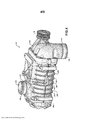
[0015] A Figura 4 é uma vista em perspectiva frontal de um exemplar de soprador rotativo do sistema de fornecimento de ar da Figura 3;[0015] Figure 4 is a front perspective view of an exemplary rotary blower of the air supply system of Figure 3;
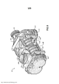
[0016] A Figura 5 é uma vista em perspectiva posterior de um exemplar do soprador rotativo da Figura 4;[0016] Figure 5 is a rear perspective view of an exemplary rotary blower of Figure 4;
[0017] A Figura 6 é uma vista lateral do exemplar do soprador rotativo da Figura 4;[0017] Figure 6 is a side view of the exemplary rotary blower of Figure 4;
[0018] A Figura 7 é uma vista em corte transversal do exemplar de soprador rotativo feita ao longo das linhas 7-7 da Figura 6;[0018] Figure 7 is a cross-sectional view of the exemplary rotary blower taken along lines 7-7 of Figure 6;
[0019] A Figura 8 é uma ilustração esquemática de um sistema de refrigeração para uma máquina agrícola construído de acordo com outro exemplo da presente divulgação; e[0019] Figure 8 is a schematic illustration of a cooling system for an agricultural machine constructed according to another example of the present disclosure; and
[0020] A Figura 9 é uma ilustração esquemática de um sistema de fornecimento de ar incluindo um sistema de limpeza de filtro de ar construído de acordo com outro exemplo da presente divulgação.[0020] Figure 9 is a schematic illustration of an air supply system including an air filter cleaning system constructed in accordance with another example of the present disclosure.
[0021] Com referência inicial as Figuras 1 e 2, um sistema de fornecimento de ar construído de acordo com um exemplo da presente divulgação é mostrado e, em geral, identificado com a referência numeral 10. O sistema de fornecimento de ar 10 é mostrado operativamente configurado em uma máquina agrícola 12. A máquina agrícola descrita aqui está na forma de uma ceifeira-debulhadora 14. Será apreciado, entretanto, que o sistema de fornecimento de ar 10, de acordo com a presente divulgação, pode ser configurado para uso em máquinas agrícolas incluindo vários outros equipamentos da ceifeira- debulhadora, máquina de fazer feno, máquina de carregamento, tratores e semelhantes. Como ficará apreciado a partir da seguinte discussão, o sistema de fornecimento de ar 10, de acordo com a presente divulgação pode reduzir uma temperatura dos gases de escape do motor emitido das máquinas agrícolas 12.[0021] With initial reference to Figures 1 and 2, an air supply system constructed in accordance with an example of the present disclosure is shown and generally identified with
[0022] O exemplar da ceifeira-debulhadora 14, em geral, inclui um chassi 16 possuindo rodas 18 que envolvem o chão. Um motor 20 fornece movimento rotativo para as rodas 18. As rodas 18, portanto, servem para mover a máquina agrícola 12 ao longo do terreno. Será apreciado que qualquer combinação das rodas frontais e posteriores 18 podem ser configuradas como rodas motrizes e rodas volantes. A operação da ceifeira-debulhadora 14 é controlada a partir da cabine do operador 22. Um cabeçote de corte 24 é montado na extremidade frontal da ceifeira- debulhadora 14 e é configurado para recolher as plantas de milho 26 crescendo em um campo agrícola e tirar as espigas de milho dos caules das plantas. Os caules das plantas, uma vez descascado de suas espigas de milho, são deixadas no solo. As espigas de milho são transportadas através do cabeçote de corte 24, para trás, até um compartimento de alimentação 28. O compartimento de alimentação 28 suporta o cabeçote de corte 24 na ceifeira-debulhadora 14. Em outros exemplos, os caules das plantas podem ser cortados do solo e todo o pé de milho pode ser alimentado para o cabeçote de corte 24 para processamento adicional.[0022] The example of the combine harvester 14 generally includes a chassis 16 having
[0023] Um transportador 30 transporta as espigas de milho para um conjunto de processamento de colheita da colheitadeira 32. O conjunto de processamento de colheita da colheitadeira 32 pode incluir um número de componentes que ainda processam as espigas de milho. Em um exemplo, o conjunto de processamento de colheita 32 inclui uma máquina debulhadora, um separador e um limpador. A máquina debulhadora e o separador podem cooperar para remover o grão dos talos e cascas. O limpador pode incluir uma peneira e um (“chaffer”) que separa o grão da poeira e da palha. Uma vez limpado, o grão limpo pode ser depositado em um transportador sem fim localizado no fundo da colheitadeira ceifeira-debulhadora 14. O grão limpo pode ser removido por um transportador de pás para um tanque de grãos 40. A colheitadeira ceifeira-debulhadora 14 pode ser periodicamente descarregada através de uma broca de descarregamento 44. Outras configurações podem ser fornecidas.[0023] A conveyor 30 transports the ears of corn to a combine harvest processing assembly 32. The combine harvest processing assembly 32 may include a number of components that further process the ears of corn. In one example, the crop processing assembly 32 includes a threshing machine, a separator and a cleaner. The threshing machine and separator can cooperate to remove grain from stalks and husks. The cleaner may include a sieve and chaffer that separates the grain from the dust and chaff. Once cleaned, the clean grain can be deposited onto an endless conveyor located at the bottom of the combine harvester 14. The cleaned grain can be removed by a paddle conveyor into a
[0024] Com referência adicional a Figura 3, o sistema de fornecimento de ar 10, de acordo com um exemplo da presente divulgação, será descrito. O sistema de fornecimento de ar 10 pode, em geral, incluir um soprador de deslocamento positivo ou super-alimentador 50 do tipo Roots e um compartimento pós- tratamento 54. O compartimento pós-tratamento 54 pode ter uma primeira entrada 55, uma segunda entrada 56 e uma saída 57. O super-alimentador 50 pode ser configurado para forçar o ar de um duto de admissão de ar 58 através de um duto de saída do super-alimentador 60 e para dentro do compartimento de pós- tratamento 54 por meio de uma primeira entrada 55. Como ficará apreciado a partir da discussão a seguir, o super-alimentador 50 é configurado para forçar o ar para dentro do compartimento de pós-tratamento 54. Uma taxa de fluxo exemplar é 350 pés cúbicos por minuto (cfm), embora outras taxas sejam contempladas. A temperatura do ar sendo forçado para o compartimento de pós-tratamento 54 pelo super-alimentador 50 é mais fria do que a temperatura de um escape 61 do motor 20. O ar mais frio fornecido a partir do super-alimentador 50 reduz a temperatura do escape 61.[0024] With further reference to Figure 3, the
[0025] Um duto de escape do motor 62 pode transmitir gases de escape do motor 20 através do compartimento de pós- tratamento 54 e para fora da colheitadeira ceifeira- debulhadora 14, através de uma saída de escape do motor 63. No exemplo mostrado, o duto de escape do motor 62 entra no compartimento de pós-tratamento 54 na segunda entrada 65 e sai do compartimento de pós-tratamento 54 na saída 57. O ar mais frio (relativo a temperatura de escape saindo do motor 20, a montante do compartimento de pós-tratamento 54) fornecido pelo super-alimentador 50 será forçado contra o duto de escape do motor 62 e através de convenção, causará a redução da temperatura do escape 61. Como resultado, a temperatura do escape 61 que sai do compartimento de pós-tratamento 54 através do duto de escape do motor 62 é menor do que a temperatura do escape 61 entrando o compartimento de pós-tratamento 54. A esse respeito, a temperatura do escape saindo da colheitadeira ceifeira-debulhadora 14 na saída de escape 63 é reduzida em comparação com a temperatura de escape saindo do motor 20, a montante do compartimento de pós-tratamento 54.[0025] An
[0026] O super-alimentador 50 pode ser acionado por uma caixa de velocidades ou tomador de força da unidade (TFU) 64 estendendo-se a partir do motor 20. Um dispositivo de transferência de energia tal como uma correia 66 pode transferir um movimento rotativo de uma polia do TFU 68 acionado pelo TFU 64 para uma polia do super-alimentador 70, posicionado no super-alimentador 50. Outros arranjos mecânicos podem ser incorporados para fornecer uma entrada rotativa a polia do super-alimentador 70.[0026] The supercharger 50 may be driven by a gearbox or unit power take-off (TFU) 64 extending from the
[0027] Um filtro de entrada 72 pode ser configurado a montante do duto de entrada de ar 58. O filtro de entrada 72 pode filtrar ar ambiente fluindo para dentro do duto de entrada de ar 58. Um sensor de vácuo 74 pode ser configurado no duto de entrada de ar 58. O sensor de vácuo 74 pode ser configurado para medir uma pressão no duto de entrada de ar 58. Um sensor de temperatura 76 pode ser fornecido no compartimento de pós- tratamento 54. O sensor de temperatura 76 pode ser configurado para medir uma temperatura no compartimento de pós-tratamento 54. Um respiradouro 78 pode ser incorporado no compartimento de pós-tratamento 54 que fará a ventilação do compartimento de pós-tratamento 54 com ar ambiente. O ar fornecido do super- alimentador 50 pode sair do compartimento de pós-tratamento 54 através do respiradouro 78. O compartimento de pós-tratamento 54 é selado, exceto o respiradouro 78. O fluxo de ar entrando no compartimento de pós-tratamento 54 a partir do super- alimentador 50 possui uma pressão maior que a ambiente. Em um exemplo, a pressão no compartimento de pós-tratamento 54 pode ser entre 110 e 120 kilopascal (kPa). Em geral, a pressão atmosférica pode variar entre 95 e 105 kPa. De tal forma, a pressão no compartimento de pós-tratamento 54 é maior do que a ambiente. A relação de pressão do compartimento de pós- tratamento 54 e a pressão atmosférica pode ser de cerca de 1,1 a 1,2. A esse respeito, contaminantes são impedidos de entrar no compartimento de pós-tratamento 54 através do respiradouro 78.[0027] An
[0028] O sensor de vácuo 74 e o sensor de temperatura 76 pode ser configurado para comunicar um sinal para um controlador (não mostrado especificamente). O controlador pode ser configurado para fazer operações de ajuste no sistema de fornecimento de ar 10 com base nas entradas operacionais, incluindo aquelas fornecidas pelo sensor de vácuo 74 e o sensor de temperatura 76. No exemplo mostrado, o sistema de fornecimento de ar 10 é posicionado dentro de um compartimento do motor 80, embora será apreciado que alguns ou todos os componentes podem estar localizados em outro lugar na colheitadeira ceifeira-debulhadora 14.[0028] The
[0029] Com referência adicional para Figuras 4-7, o super- alimentador 50 será ainda descrito. O super-alimentador 50 pode, em geral, incluir um alojamento de super-alimentação 100 possuindo uma porção de alojamento frontal 102, uma porção de alojamento central 104 e uma porção de alojamento posterior 106. A porção de alojamento frontal 102 pode incluir uma porta de entrada 110 definida por um cilindro de entrada 112. A porção de entrada 110 pode se estender ao longo de um eixo de porta de entrada 114 (Figura 6) e definir uma seção circular transversal. Nervuras de montagem 116 (Figura 6 podem se estender ao redor do cilindro de entrada 112 para fornecer uma estrutura de acoplamento para o duto de entrada de ar 58 (Figura 3). A porção de alojamento frontal 102 pode fornecer estrutura de montagem para a polia de super-alimentação 70.[0029] With further reference to Figures 4-7, the superfeeder 50 will be further described. The supercharger 50 may generally include a
[0030] A porção de alojamento central 104 pode incluir uma pluralidade de aletas de refrigeração 120 estendendo-se dela. A porção de alojamento central 104 pode incluir uma porção de saída 130 definida por um cilindro de saída 132. A porção de saída 130 pode se estender ao longo de um eixo da porção de saída 134 (Figura 6) e definir uma seção transversal circular. Uma nervura de montagem 136 pode estender-se ao redor do cilindro de saída 132 para prover uma estrutura de acoplamento para o duto de saída do super-alimentador 60 (Figura 3).[0030] The
[0031] A porção de alojamento central 104 pode incluir um orifício 140 estendendo-se dali. O orifício 140 pode definir uma abertura 142 possuindo um eixo 144 que é paralelo ao eixo da porta de entrada 114 e ao eixo da porta de saída 134. O orifício 140 pode ser monoliticamente ou integralmente formado com a porção de alojamento central 104 e pode ser usado, por exemplo, como um ponto de agarramento ou ponto de montagem, para mover o super-alimentador 50 durante montagem.[0031] The
[0032] O super-alimentador 50 inclui um primeiro rotor 152 e um segundo rotor 154, ambos os quais incluem uma pluralidade de lóbulos gradeados. Os rotores 152 e 154 são dispostos em um par de câmaras cilíndricas sobrepostas paralelamente, transversalmente 156, 158, respectivamente definidos na porção de alojamento central 104. Os rotores 152 e 154 são acionados mecanicamente por movimento de torção do virabrequim do motor, transmitido através da correia 66. O primeiro e segundo rotores 152 e 154 são acionados a uma razão fixa, aumentando assim ou super-alimentando o fluxo de ar da porta de entrada 110 para a porta de saída 130.[0032] The superfeeder 50 includes a
[0033] O primeiro rotor 152 é fixamente montado a um primeiro eixo de rotor 162 que é mancalizado (“journalled”) para rotação no alojamento de super-alimentação 100. Em um exemplo, o primeiro eixo de rotor 162 inclui uma primeira extremidade 164. Uma segunda extremidade 166 do primeiro eixo de rotor 162 inclui uma primeira engrenagem de dente reto 168 montada nela. Um primeiro cubo de montagem do rotor 170 pode ser formado na primeira engrenagem de dentes retos 168. O primeiro cubo de montagem do rotor 170 pode ser rotativamente mancalizado (“journalled”) em um furo correspondente (não mostrado especificamente) na porção de alojamento posterior 106.[0033] The
[0034] O segundo rotor 154 é fixadamente montado a um segundo eixo de rotor 172 que é mancalizado para rotação no alojamento de super-alimentação 100. Em um exemplo, o segundo eixo de rotor 172 inclui uma primeira extremidade 174. Uma segunda extremidade 176 do segundo eixo de rotor 172 inclui uma segunda engrenagem de dentes retos 178 que é entrosamente engatada à primeira engrenagem de dentes retos 168 para rotação simultânea. Um segundo cubo de montagem do rotor 180 pode ser formado na segunda engrenagem de dentes retos 178. A segunda engrenagem de dentes retos 180 pode ser mancada de forma rotacional em um furo correspondente (não especificamente mostrado) na porção de alojamento posterior 106.[0034] The second rotor 154 is fixedly mounted to a second rotor shaft 172 which is bushed for rotation in the
[0035] Com referência a Figura 8, um sistema de refrigeração construído de acordo com outro exemplo da presente divulgação é mostrado e, em geral, identificado com referência numérica 210. O sistema de refrigeração 210 pode, em geral, incluir um super-alimentador 250 que pode ser configurado para forçar ar a partir do duto de entrada de ar 258 através de um coletor 260 que direciona ar contra o turbocompressor 270 e o acessório 272 pode resfriar o turbocompressor 270 e o acessório 272. O acessório 272 pode ser qualquer componente em uma máquina agrícola que precisa ser resfriado. Por meio de um exemplo não limitante, o acessório 272 pode incluir um acessório de motor, um óleo de motor, e/ou um líquido de refrigeração do motor. Será apreciado que o coletor 260 pode ser configurado para direcionar ar para somente um turbocompressor 270 e acessório 272. Em um exemplo, o super-alimentador pode ser parte do sistema de fornecimento de escape 254, tal como descrito acima.[0035] With reference to Figure 8, a cooling system constructed in accordance with another example of the present disclosure is shown and generally identified with
[0036] O super-alimentador 250 pode ser acionado por uma caixa de velocidades ou TFU 264 estendendo-se do motor 220 de maneira similar a configuração descrita acima com o super- alimentador 50. Em uma configuração, uma válvula tal como uma válvula borboleta 280 pode ser incorporada no coletor 260. A válvula borboleta 280 pode ser seletivamente ativada por um controlador 282 para modificar a taxa de ar fornecido ao turbocompressor 270 e ao acessório 272. Um filtro de ar 290 pode ser configurado a montante da entrada 258 para filtrar o ar entrando no super-alimentador 250.[0036] The
[0037] Com referência a Figura 9, um sistema de fornecimento de ar construído de acordo com um exemplo da presente divulgação é mostrado e, em geral, identificado com a referência numérica 310. O sistema de fornecimento de ar 310 pode incluir um super-alimentador 350 que pode ser configurado para forçar ar a partir de um duto de entrada de ar 358B através de um coletor 360 que direciona ar para um filtro de ar 370. Especificamente, o coletor 360 direciona ar em uma direção 372, oposta uma direção 374 de entrada de ar para o motor 330 para limpar o filtro de ar do motor 370. Conforme explicado, conforme o ar é direcionado para o motor 330, o ar pode ser primeiro encaminhado através do filtro de ar 370. Com o tempo, o filtro de ar 370 pode coletar sujeira e detritos e assim, reduzir o fluxo de ar permissível através do filtro de ar 370. Quando ar é forçado do super-alimentador 350 na direção 372, tais sujeiras e detritos podem ser impelidos para fora ou afastados do filtro de ar 370, aumentado a vida útil do filtro de ar 370. Em alguns exemplos, o ar do super-alimentador 350 pode ser enviado em correntes de ar intermitentes. Uma válvula 380 pode ser incorporada, que é ativada por um controlador 382 para controlar a temporização de tais correntes de ar. Enquanto não especificamente mostrado, o super-alimentador 350 pode ser parte de um sistema de fornecimento de ar, tal como descrito acima.[0037] With reference to Figure 9, an air supply system constructed in accordance with an example of the present disclosure is shown and generally identified with
[0038] O super-alimentador pode ser acionado por uma caixa de velocidades ou TFU 384 estendendo-se do motor 320 de maneira similar a configuração descrita acima com o super-alimentador 50. Um filtro de ar 390 pode ser configurado a montante da entrada 358 para filtrar o ar entrando no super-alimentador 350.[0038] The supercharger can be driven by a gearbox or
[0039] A descrição precedente das concretizações foi fornecida para propósitos de ilustração e descrição. Não é pretendido ser exaustivo ou limitar a divulgação. Elementos individuais ou características de uma concretização particular são em geral não limitados a essa concretização particular, mas onde aplicável, são intercambiáveis e podem ser usadas em uma concretização selecionada, mesmo que não especificamente mostrada ou descrita. O mesmo pode também ser variado em muitas maneiras. Tais variações não são para ser consideradas como uma saída da divulgação, e todas essas modificações são pretendidas para serem incluídas dentro do escopo da divulgação.[0039] The foregoing description of the embodiments has been provided for purposes of illustration and description. It is not intended to be exhaustive or to limit disclosure. Individual elements or features of a particular embodiment are generally not limited to that particular embodiment, but where applicable, are interchangeable and may be used in a selected embodiment, even if not specifically shown or described. The same can also be varied in many ways. Such variations are not to be considered as a departure from the disclosure, and all such modifications are intended to be included within the scope of the disclosure.
Claims (20)
Applications Claiming Priority (3)
| Application Number | Priority Date | Filing Date | Title |
|---|---|---|---|
| US201461931231P | 2014-01-24 | 2014-01-24 | |
| US61/931,231 | 2014-01-24 | ||
| PCT/US2015/012237 WO2015112593A1 (en) | 2014-01-24 | 2015-01-21 | Cooling system and air delivery system for a farm machine |
Publications (2)
| Publication Number | Publication Date |
|---|---|
| BR112016016910A2 BR112016016910A2 (en) | 2017-08-08 |
| BR112016016910B1 true BR112016016910B1 (en) | 2022-11-16 |
Family
ID=53681900
Family Applications (1)
| Application Number | Title | Priority Date | Filing Date |
|---|---|---|---|
| BR112016016910-7A BR112016016910B1 (en) | 2014-01-24 | 2015-01-21 | REFRIGERATION SYSTEM FOR COOLING PORTIONS OF AN AGRICULTURAL MACHINE, AIR SUPPLY SYSTEM FOR AN AGRICULTURAL MACHINE AND METHOD FOR COOLING PORTIONS OF AN AGRICULTURAL MACHINE |
Country Status (5)
| Country | Link |
|---|---|
| US (1) | US10085377B2 (en) |
| EP (1) | EP3097283B1 (en) |
| CN (1) | CN105980683B (en) |
| BR (1) | BR112016016910B1 (en) |
| WO (1) | WO2015112593A1 (en) |
Families Citing this family (2)
| Publication number | Priority date | Publication date | Assignee | Title |
|---|---|---|---|---|
| CN110508067A (en) * | 2018-05-22 | 2019-11-29 | 株式会社久保田 | Working rig |
| JP7004612B2 (en) * | 2018-06-22 | 2022-01-21 | 株式会社クボタ | combine |
Family Cites Families (30)
| Publication number | Priority date | Publication date | Assignee | Title |
|---|---|---|---|---|
| US3748836A (en) * | 1971-06-03 | 1973-07-31 | Teledyne Inc | Filter cleaning system for internal combustion engine |
| US3820327A (en) | 1972-05-10 | 1974-06-28 | Peugeot & Renault | Temperature regulator for a catalytic reactor |
| JPS5232019B2 (en) | 1973-01-13 | 1977-08-18 | ||
| JPS5141107A (en) * | 1974-10-03 | 1976-04-06 | Nissan Motor | |
| DE3564601D1 (en) * | 1984-03-27 | 1988-09-29 | Mazda Motor | Engine intake system having a supercharger |
| US4564346A (en) * | 1984-09-04 | 1986-01-14 | Eaton Corporation | Supercharger with hourglass outlet port |
| JPH01100319A (en) * | 1987-10-14 | 1989-04-18 | Sanden Corp | Mechanical supercharger |
| JPH0510282A (en) | 1990-09-21 | 1993-01-19 | Ntn Corp | Supercharger |
| DE19701874C5 (en) * | 1997-01-21 | 2006-06-22 | Daimlerchrysler Ag | Camshaft bearing assembly in the cylinder head of an internal combustion engine |
| US5987885A (en) | 1998-01-29 | 1999-11-23 | Chrysler Corporation | Combination catalytic converter and heat exchanger that maintains a catalyst substrate within an efficient operating temperature range for emmisions reduction |
| US6358109B1 (en) * | 1999-12-08 | 2002-03-19 | Bombardier Motor Corporation Of America | Air cooled marine engine exhaust |
| AT4964U1 (en) | 2001-02-15 | 2002-01-25 | Avl List Gmbh | INTERNAL COMBUSTION ENGINE WITH AN EXHAUST SYSTEM |
| DE10335261A1 (en) * | 2003-08-01 | 2005-02-17 | Daimlerchrysler Ag | Compressor and / or turbine wheel for a secondary air conveyor |
| DE10350485A1 (en) * | 2003-10-29 | 2005-06-02 | Robert Bosch Gmbh | Method for operating an internal combustion engine |
| KR100579265B1 (en) * | 2003-12-24 | 2006-05-11 | 현대자동차주식회사 | Intake apparatus for vehicle |
| JP2005220778A (en) | 2004-02-04 | 2005-08-18 | Toyota Motor Corp | Supercharging internal combustion engine with exhaust system cooling air flow path |
| DE102006027449A1 (en) * | 2006-06-12 | 2007-12-13 | Mann + Hummel Gmbh | Diesel internal combustion engine operating method involves feeding air, filtered by air filter, through intake section of internal combustion engine and conducting secondary air over secondary compressor in exhaust gas tract |
| DE102006057791A1 (en) | 2006-12-06 | 2008-06-12 | Claas Selbstfahrende Erntemaschinen Gmbh | Compressed air system for a vehicle |
| JP4341689B2 (en) * | 2007-04-18 | 2009-10-07 | トヨタ自動車株式会社 | Secondary air supply device for internal combustion engine |
| IT1398932B1 (en) * | 2009-07-14 | 2013-03-28 | Urbani | AGRICULTURAL / INDUSTRIAL MACHINE EQUIPPED WITH A CLEANING SYSTEM WITH GAS IN PRESSURE. |
| US8813492B2 (en) * | 2009-10-14 | 2014-08-26 | Hansen Engine Corporation | Internal combustion engine and supercharger |
| US8539769B2 (en) | 2009-10-14 | 2013-09-24 | Craig N. Hansen | Internal combustion engine and supercharger |
| DE102010011293B4 (en) | 2010-03-13 | 2022-07-07 | Dr. Ing. H.C. F. Porsche Aktiengesellschaft | internal combustion engine |
| JP5488124B2 (en) * | 2010-03-31 | 2014-05-14 | トヨタ自動車株式会社 | Control device for internal combustion engine |
| US8206476B2 (en) | 2010-04-01 | 2012-06-26 | Deere & Company | Cover for a diesel particulate filter |
| US8042335B2 (en) | 2010-06-03 | 2011-10-25 | Ford Global Technologies, Llc | Intake air heating and exhaust cooling |
| US9032715B2 (en) | 2011-03-24 | 2015-05-19 | Brb/Sherline, Inc. | Method of increasing volumetric throughput of internal combustion engines used in vapor destruction applications |
| JP6091497B2 (en) | 2011-06-02 | 2017-03-08 | イートン コーポレーションEaton Corporation | Simplified roots-type blower |
| US9683521B2 (en) * | 2013-10-31 | 2017-06-20 | Eaton Corporation | Thermal abatement systems |
| US20160040574A1 (en) * | 2014-08-08 | 2016-02-11 | Deere & Company | Arrangement for providing an aftertreatment device housing with air |
-
2015
- 2015-01-21 CN CN201580005481.8A patent/CN105980683B/en active Active
- 2015-01-21 WO PCT/US2015/012237 patent/WO2015112593A1/en active Application Filing
- 2015-01-21 BR BR112016016910-7A patent/BR112016016910B1/en active IP Right Grant
- 2015-01-21 EP EP15740047.4A patent/EP3097283B1/en active Active
-
2016
- 2016-07-21 US US15/216,213 patent/US10085377B2/en active Active
Also Published As
| Publication number | Publication date |
|---|---|
| US20160324069A1 (en) | 2016-11-10 |
| WO2015112593A1 (en) | 2015-07-30 |
| CN105980683A (en) | 2016-09-28 |
| EP3097283A4 (en) | 2017-10-18 |
| CN105980683B (en) | 2019-10-18 |
| BR112016016910A2 (en) | 2017-08-08 |
| EP3097283B1 (en) | 2020-04-29 |
| EP3097283A1 (en) | 2016-11-30 |
| US10085377B2 (en) | 2018-10-02 |
Similar Documents
| Publication | Publication Date | Title |
|---|---|---|
| BR102016006558B1 (en) | GRAIN HANDLING ARRANGEMENT FOR AN AGRICULTURAL COMBINED | |
| CN108289414B (en) | Harvester | |
| JP2019076034A (en) | Harvester | |
| US10137768B2 (en) | Air delivery system for a farm machine | |
| US10225988B2 (en) | Agricultural elevator supplied by multiple cross augers | |
| BR112016016910B1 (en) | REFRIGERATION SYSTEM FOR COOLING PORTIONS OF AN AGRICULTURAL MACHINE, AIR SUPPLY SYSTEM FOR AN AGRICULTURAL MACHINE AND METHOD FOR COOLING PORTIONS OF AN AGRICULTURAL MACHINE | |
| JP6842950B2 (en) | combine | |
| US11051453B2 (en) | Reel drive assembly for an agricultural header | |
| EP3230567B1 (en) | Transversely oriented cooling package for an agricultural harvester | |
| JP2009060835A (en) | Threshing apparatus and combine harvester | |
| BR112017015550B1 (en) | DRIVE SYSTEM FOR HARVESTING AND THRESHING HARVEST MACHINE AND METHOD TO PROVIDE THE SAME | |
| US3169357A (en) | Pneumatic harvester and thresher | |
| CN205336916U (en) | But biax rotates small -size automatic corn thresher who threshes | |
| CN1084587C (en) | Axial feeding grains combine | |
| JP4445100B2 (en) | Combine | |
| CN219305469U (en) | Combine harvester | |
| WO2005060729A1 (en) | Combine | |
| WO2005060731A1 (en) | Combine | |
| WO2019082308A1 (en) | Combine harvester | |
| WO2019082307A1 (en) | Combine harvester | |
| JP2017012002A (en) | combine | |
| JP2013027337A (en) | Combine harvester | |
| CN114679954A (en) | Working vehicle | |
| KR20200093806A (en) | Combine | |
| JP2012019798A (en) | Combine harvester |
Legal Events
| Date | Code | Title | Description |
|---|---|---|---|
| B06U | Preliminary requirement: requests with searches performed by other patent offices: procedure suspended [chapter 6.21 patent gazette] | ||
| B25G | Requested change of headquarter approved |
Owner name: EATON CORPORATION (US) |
|
| B25A | Requested transfer of rights approved |
Owner name: EATON INTELLIGENT POWER LIMITED (IE) |
|
| B09A | Decision: intention to grant [chapter 9.1 patent gazette] | ||
| B16A | Patent or certificate of addition of invention granted [chapter 16.1 patent gazette] |
Free format text: PRAZO DE VALIDADE: 20 (VINTE) ANOS CONTADOS A PARTIR DE 21/01/2015, OBSERVADAS AS CONDICOES LEGAIS |