BR112016011607B1 - WIRED PIPE AND METHOD TO FORM A WIRED PIPE - Google Patents
WIRED PIPE AND METHOD TO FORM A WIRED PIPE Download PDFInfo
- Publication number
- BR112016011607B1 BR112016011607B1 BR112016011607-0A BR112016011607A BR112016011607B1 BR 112016011607 B1 BR112016011607 B1 BR 112016011607B1 BR 112016011607 A BR112016011607 A BR 112016011607A BR 112016011607 B1 BR112016011607 B1 BR 112016011607B1
- Authority
- BR
- Brazil
- Prior art keywords
- channel
- pipe
- barrel body
- wall
- transmission line
- Prior art date
Links
Images


Classifications
-
- E—FIXED CONSTRUCTIONS
- E21—EARTH DRILLING; MINING
- E21B—EARTH DRILLING, e.g. DEEP DRILLING; OBTAINING OIL, GAS, WATER, SOLUBLE OR MELTABLE MATERIALS OR A SLURRY OF MINERALS FROM WELLS
- E21B17/00—Drilling rods or pipes; Flexible drill strings; Kellies; Drill collars; Sucker rods; Cables; Casings; Tubings
- E21B17/003—Drilling rods or pipes; Flexible drill strings; Kellies; Drill collars; Sucker rods; Cables; Casings; Tubings with electrically conducting or insulating means
-
- B—PERFORMING OPERATIONS; TRANSPORTING
- B21—MECHANICAL METAL-WORKING WITHOUT ESSENTIALLY REMOVING MATERIAL; PUNCHING METAL
- B21C—MANUFACTURE OF METAL SHEETS, WIRE, RODS, TUBES OR PROFILES, OTHERWISE THAN BY ROLLING; AUXILIARY OPERATIONS USED IN CONNECTION WITH METAL-WORKING WITHOUT ESSENTIALLY REMOVING MATERIAL
- B21C23/00—Extruding metal; Impact extrusion
- B21C23/02—Making uncoated products
- B21C23/04—Making uncoated products by direct extrusion
- B21C23/08—Making wire, bars, tubes
- B21C23/085—Making tubes
-
- B—PERFORMING OPERATIONS; TRANSPORTING
- B21—MECHANICAL METAL-WORKING WITHOUT ESSENTIALLY REMOVING MATERIAL; PUNCHING METAL
- B21C—MANUFACTURE OF METAL SHEETS, WIRE, RODS, TUBES OR PROFILES, OTHERWISE THAN BY ROLLING; AUXILIARY OPERATIONS USED IN CONNECTION WITH METAL-WORKING WITHOUT ESSENTIALLY REMOVING MATERIAL
- B21C25/00—Profiling tools for metal extruding
- B21C25/04—Mandrels
-
- B—PERFORMING OPERATIONS; TRANSPORTING
- B21—MECHANICAL METAL-WORKING WITHOUT ESSENTIALLY REMOVING MATERIAL; PUNCHING METAL
- B21C—MANUFACTURE OF METAL SHEETS, WIRE, RODS, TUBES OR PROFILES, OTHERWISE THAN BY ROLLING; AUXILIARY OPERATIONS USED IN CONNECTION WITH METAL-WORKING WITHOUT ESSENTIALLY REMOVING MATERIAL
- B21C37/00—Manufacture of metal sheets, bars, wire, tubes or like semi-manufactured products, not otherwise provided for; Manufacture of tubes of special shape
- B21C37/06—Manufacture of metal sheets, bars, wire, tubes or like semi-manufactured products, not otherwise provided for; Manufacture of tubes of special shape of tubes or metal hoses; Combined procedures for making tubes, e.g. for making multi-wall tubes
- B21C37/15—Making tubes of special shape; Making tube fittings
- B21C37/151—Making tubes with multiple passages
-
- B—PERFORMING OPERATIONS; TRANSPORTING
- B29—WORKING OF PLASTICS; WORKING OF SUBSTANCES IN A PLASTIC STATE IN GENERAL
- B29C—SHAPING OR JOINING OF PLASTICS; SHAPING OF MATERIAL IN A PLASTIC STATE, NOT OTHERWISE PROVIDED FOR; AFTER-TREATMENT OF THE SHAPED PRODUCTS, e.g. REPAIRING
- B29C48/00—Extrusion moulding, i.e. expressing the moulding material through a die or nozzle which imparts the desired form; Apparatus therefor
- B29C48/03—Extrusion moulding, i.e. expressing the moulding material through a die or nozzle which imparts the desired form; Apparatus therefor characterised by the shape of the extruded material at extrusion
- B29C48/09—Articles with cross-sections having partially or fully enclosed cavities, e.g. pipes or channels
-
- B—PERFORMING OPERATIONS; TRANSPORTING
- B29—WORKING OF PLASTICS; WORKING OF SUBSTANCES IN A PLASTIC STATE IN GENERAL
- B29C—SHAPING OR JOINING OF PLASTICS; SHAPING OF MATERIAL IN A PLASTIC STATE, NOT OTHERWISE PROVIDED FOR; AFTER-TREATMENT OF THE SHAPED PRODUCTS, e.g. REPAIRING
- B29C48/00—Extrusion moulding, i.e. expressing the moulding material through a die or nozzle which imparts the desired form; Apparatus therefor
- B29C48/03—Extrusion moulding, i.e. expressing the moulding material through a die or nozzle which imparts the desired form; Apparatus therefor characterised by the shape of the extruded material at extrusion
- B29C48/131—Curved articles
-
- B—PERFORMING OPERATIONS; TRANSPORTING
- B29—WORKING OF PLASTICS; WORKING OF SUBSTANCES IN A PLASTIC STATE IN GENERAL
- B29C—SHAPING OR JOINING OF PLASTICS; SHAPING OF MATERIAL IN A PLASTIC STATE, NOT OTHERWISE PROVIDED FOR; AFTER-TREATMENT OF THE SHAPED PRODUCTS, e.g. REPAIRING
- B29C48/00—Extrusion moulding, i.e. expressing the moulding material through a die or nozzle which imparts the desired form; Apparatus therefor
- B29C48/25—Component parts, details or accessories; Auxiliary operations
- B29C48/285—Feeding the extrusion material to the extruder
- B29C48/288—Feeding the extrusion material to the extruder in solid form, e.g. powder or granules
- B29C48/2883—Feeding the extrusion material to the extruder in solid form, e.g. powder or granules of preformed parts, e.g. inserts fed and transported generally uninfluenced through the extruder or inserts fed directly to the die
-
- B—PERFORMING OPERATIONS; TRANSPORTING
- B29—WORKING OF PLASTICS; WORKING OF SUBSTANCES IN A PLASTIC STATE IN GENERAL
- B29C—SHAPING OR JOINING OF PLASTICS; SHAPING OF MATERIAL IN A PLASTIC STATE, NOT OTHERWISE PROVIDED FOR; AFTER-TREATMENT OF THE SHAPED PRODUCTS, e.g. REPAIRING
- B29C48/00—Extrusion moulding, i.e. expressing the moulding material through a die or nozzle which imparts the desired form; Apparatus therefor
- B29C48/03—Extrusion moulding, i.e. expressing the moulding material through a die or nozzle which imparts the desired form; Apparatus therefor characterised by the shape of the extruded material at extrusion
- B29C48/09—Articles with cross-sections having partially or fully enclosed cavities, e.g. pipes or channels
- B29C48/11—Articles with cross-sections having partially or fully enclosed cavities, e.g. pipes or channels comprising two or more partially or fully enclosed cavities, e.g. honeycomb-shaped
-
- B—PERFORMING OPERATIONS; TRANSPORTING
- B29—WORKING OF PLASTICS; WORKING OF SUBSTANCES IN A PLASTIC STATE IN GENERAL
- B29C—SHAPING OR JOINING OF PLASTICS; SHAPING OF MATERIAL IN A PLASTIC STATE, NOT OTHERWISE PROVIDED FOR; AFTER-TREATMENT OF THE SHAPED PRODUCTS, e.g. REPAIRING
- B29C48/00—Extrusion moulding, i.e. expressing the moulding material through a die or nozzle which imparts the desired form; Apparatus therefor
- B29C48/25—Component parts, details or accessories; Auxiliary operations
- B29C48/30—Extrusion nozzles or dies
- B29C48/32—Extrusion nozzles or dies with annular openings, e.g. for forming tubular articles
-
- B—PERFORMING OPERATIONS; TRANSPORTING
- B29—WORKING OF PLASTICS; WORKING OF SUBSTANCES IN A PLASTIC STATE IN GENERAL
- B29L—INDEXING SCHEME ASSOCIATED WITH SUBCLASS B29C, RELATING TO PARTICULAR ARTICLES
- B29L2023/00—Tubular articles
- B29L2023/22—Tubes or pipes, i.e. rigid
-
- B—PERFORMING OPERATIONS; TRANSPORTING
- B29—WORKING OF PLASTICS; WORKING OF SUBSTANCES IN A PLASTIC STATE IN GENERAL
- B29L—INDEXING SCHEME ASSOCIATED WITH SUBCLASS B29C, RELATING TO PARTICULAR ARTICLES
- B29L2024/00—Articles with hollow walls
- B29L2024/006—Articles with hollow walls multi-channelled
Abstract
cano com fio e método para fabricar cano com fio. trata-se de um cano com fio que inclui um corpo de cano tubular que tem uma parede. a parede inclui uma superfície interna, um canal de fluxo formado pela superfície interna, uma superfície externa e pelo menos um canal formado de modo integral dentro de uma espessura da parede e entre as superfícies interna e externa da parede. também está incluído um método para formar um cano com fio.wired pipe and method of making wired pipe. it is a wired pipe that includes a tubular pipe body that has a wall. the wall includes an inner surface, a flow channel formed by the inner surface, an outer surface and at least one integrally formed channel within a wall thickness and between the inner and outer surfaces of the wall. a method for forming a wired pipe is also included.
Description
[001] Este pedido reivindica o benefício do Pedido no U.S.14/087422, depositado em 22 de novembro 2013, que é incorporado ao presente documento a título de referência em sua totalidade.[001] This application claims the benefit of Application No. U.S.14/087422, filed November 22, 2013, which is incorporated herein by reference in its entirety.
[002] Na indústria de perfuração e completação, a formação de poços para o propósito de produção ou injeção de fluido é comum. Os poços são usados para exploração ou extração de recursos naturais, como hidrocarbonetos, óleo, gás, água e, de modo alternativo para sequestro de CO2. Durante as operações de perfuração e completação subterrânea, um cano ou outro conduto é rebaixado no furo de baixo em uma formação de terra durante ou após as operações de perfuração. Tais canos são, em geral, configurados como múltiplos segmentos de cano para formar uma coluna, como uma coluna de perfuração ou coluna de produção. Conforme a coluna é rebaixada no furo de baixo, segmentos de cano adicionais são acoplados à coluna por diversos mecanismos de acoplamento, como acoplamentos rosqueados.[002] In the drilling and completion industry, the formation of wells for the purpose of production or fluid injection is common. Wells are used for exploration or extraction of natural resources such as hydrocarbons, oil, gas, water and alternatively for CO2 sequestration. During underground drilling and completion operations, a pipe or other conduit is recessed into the bottom hole in an earth formation during or after drilling operations. Such pipes are generally configured as multiple pipe segments to form a column, such as a drill string or production string. As the column is lowered into the bottom hole, additional pipe segments are attached to the column by various coupling mechanisms, such as threaded couplings.
[003] Diversos sinais de energia e/ou comunicação podem ser transmitidos através dos segmentos de cano por meio de uma configuração de “cano com fio”. Tais configurações incluem condutores elétricos, ópticos ou outros condutores que se estendem ao longo do comprimento de segmentos de cano selecionados. Os condutores são conectados de modo operável entre os segmentos de cano por uma configuração de acoplamento, como uma conexão de caixa de pinos. Um recurso de um sistema de cano com fio é que o mesmo pode transmitir dados de uma localização de fundo de poço para a superfície de modo rápido e vice-versa.[003] Various power and/or communication signals can be transmitted through the pipe segments via a “wired pipe” configuration. Such configurations include electrical, optical, or other conductors that span the length of selected pipe segments. Conductors are operably connected between pipe segments by a mating configuration, such as a pin box connection. A feature of a wired pipe system is that it can transmit data from a downhole location to the surface quickly and vice versa.
[004] Em geral, em configurações de cano com fio, um ou mais condutores, como fios ou cabos estão dispostos ao longo do diâmetro interno de um segmento de cano tipicamente de aço. Diversas configurações foram propostas para fixar, prender e blindar um fio em relação à superfície de diâmetro interior do segmento de cano. Os condutores exigem proteção contra fluido de perfuração ou produção e outros objetos (como, dardos de cimentação) que são bombeados do fundo de poço ou que fluem através dos segmentos de cano. Os mecanismos para proteger os condutores incluem tubulações de aço protetoras de diâmetro pequeno. Embora tais tubulações sirvam para proteger os condutores, as mesmas representam um obstáculo potencial para fluxo de fluido eficaz e componentes, como ferramentas de medição de cabo de aço e equipamento de cimentação que estão dispostos nos segmentos de cano.[004] In general, in wired pipe configurations, one or more conductors such as wires or cables are arranged along the inside diameter of a typically steel pipe segment. Various configurations have been proposed to secure, secure and shield a wire from the inside diameter surface of the pipe segment. Conductors require protection from drilling or production fluid and other objects (such as cement darts) that are pumped from the downhole or that flow through pipe segments. Mechanisms to protect conductors include small diameter protective steel tubing. While such pipes serve to protect the conductors, they pose a potential obstacle to effective fluid flow and components such as wire rope measuring tools and cementing equipment that are arranged in the pipe segments.
[005] Devido a crescente sofisticação de sistemas de fundo de poço, a técnica seria receptiva às disposições alternativas de cano com fios e métodos para implantação de fios no cano.[005] Due to the increasing sophistication of downhole systems, the technique would be amenable to alternative wired pipe arrangements and methods for implanting wires into the pipe.
[006] Um cano com fio inclui um corpo de cano tubular que tem uma parede, em que a parede inclui uma superfície interna, um canal de fluxo formado pela superfície interna, uma superfície externa e pelo menos um canal formado de modo integral dentro de uma espessura da parede e entre as superfícies interna e externa da parede.[006] A wired pipe includes a tubular pipe body having a wall, wherein the wall includes an inner surface, a flow channel formed by the inner surface, an outer surface, and at least one channel integrally formed within a wall thickness and between the inner and outer wall surfaces.
[007] Um método para formar um cano com fio, em que o método inclui extrudar um corpo de cano tubular com uma parede que tem uma superfície externa e uma superfície interna, em que a superfície interna forma um canal de fluxo interior e formar pelo menos um canal através de uma espessura da parede do corpo de cano tubular, entre as superfícies interna e externa.[007] A method of forming a wired pipe, wherein the method includes extruding a tubular pipe body with a wall having an outer surface and an inner surface, wherein the inner surface forms an inner flow channel and forming at least at least one channel through a wall thickness of the tubular barrel body, between the inner and outer surfaces.
[008] Agora, em referência aos desenhos em que elementos similares são numerados de modo semelhante nas diversas Figuras:[008] Now, in reference to the drawings in which similar elements are numbered similarly in the different Figures:
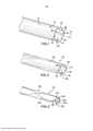
[009] A Figura 1 mostra uma vista em perspectiva lateral de uma porção de uma modalidade exemplificativa de um corpo de cano para um cano com fio;[009] Figure 1 shows a side perspective view of a portion of an exemplary embodiment of a barrel body for a wired barrel;
[010] A Figura 2 mostra uma vista em perspectiva lateral de uma porção de outra modalidade exemplificativa de um corpo de cano para um cano com fio;[010] Figure 2 shows a side perspective view of a portion of another exemplary embodiment of a barrel body for a wired barrel;
[011] A Figura 3 mostra uma vista em perspectiva lateral de uma porção de ainda outra modalidade exemplificativa de um corpo de cano para um cano com fio;[011] Figure 3 shows a side perspective view of a portion of yet another exemplary embodiment of a barrel body for a wired barrel;
[012] A Figura 4 mostra uma vista em corte de uma modalidade exemplificativa de uma ferramenta de fabricação para formar um cano com fio;[012] Figure 4 shows a sectional view of an exemplary embodiment of a manufacturing tool for forming a wired pipe;
[013] A Figura 5 mostra uma vista em perspectiva lateral de outra modalidade exemplificativa de uma ferramenta de fabricação para formar um cano com fio;[013] Figure 5 shows a side perspective view of another exemplary embodiment of a manufacturing tool for forming a wired pipe;
[014] A Figura 6 mostra uma vista em perspectiva de extremidade de outra ferramenta de fabricação exemplificativa;[014] Figure 6 shows an end perspective view of another exemplary manufacturing tool;
[015] A Figura 7 mostra uma vista em perspectiva lateral da ferramenta de fabricação da Figura 5;[015] Figure 7 shows a side perspective view of the manufacturing tool of Figure 5;
[016] A Figura 8 mostra uma vista de raios X em perspectiva lateral da ferramenta de fabricação da Figura 5;[016] Figure 8 shows an X-ray view in side perspective of the manufacturing tool of Figure 5;
[017] A Figura 9 mostra uma vista de raios X em perspectiva lateral de uma modalidade exemplificativa de uma articulação de ferramenta fixada a uma modalidade exemplificativa de um cano com fio; e[017] Figure 9 shows an X-ray view in side perspective of an exemplary embodiment of a tool joint attached to an exemplary embodiment of a wired barrel; and
[018] A Figura 10 mostra uma vista em corte transversal de uma modalidade exemplificativa de uma linha de transmissão para uso no cano com fio.[018] Figure 10 shows a cross-sectional view of an exemplary embodiment of a transmission line for use in wired pipe.
[019] As modalidades exemplificativas de um cano com fio 10 (Figura 9) utilizam um corpo de cano tubular, conforme mostrado nas Figuras 1 a 3, com um canal de comunicação de sinal para uma linha de transmissão, como um condutor elétrico isolado, fio, cabo e/ou fibra óptica. O canal é formado durante a fabricação do corpo de cano. A Figura 1 mostra uma modalidade exemplificativa de um corpo de cano 12 que tem um eixo geométrico longitudinal 14 e um ou mais canais de fio helicoidal 16 formados dentro de uma parede 18 do corpo de cano 12, de uma primeira extremidade 20 para uma segunda extremidade (não mostrada) do corpo de cano 12. Embora a expressão “canal de fio” seja usada, deve ser entendido que qualquer linha pode ser acomodada dentro do canal de fio, como, porém, sem limitação, um condutor elétrico isolado, fio, cabo e/ou fibra óptica. O canal de fio helicoidal 16 está no formato de uma hélice que compartilha o eixo geométrico longitudinal 14 do corpo de cano 12 e que inclui uma ou mais voltas helicoidais, dependendo do comprimento do cano com fio 10. O ângulo de hélice do canal de fio helicoidal 16 pode ser dependente das dimensões gerais do cano com fio 10. A parede 18 inclui uma superfície externa 22 e uma superfície interna 24 e os canais de fio helicoidal 16 são formados entre as superfícies interna e externa 22, 24 da parede 18, dentro de uma espessura 26 da parede 18. Na modalidade ilustrada da Figura 1, a espessura 26 da parede 18 é maior nas localizações do canal de fio helicoidal 16, de modo que um diâmetro interno do corpo de cano 12 não seja constante e seja menor em localizações em que os canais de fio 16 estejam localizados e maior onde os canais de fio 16 não estão localizados. Um diâmetro externo do corpo de cano 12 é substancialmente constante. Um canal de fluxo 28 é fornecido dentro de um interior 30 do corpo de cano 12, em que o canal de fluxo 28 circundado pela superfície interna 24 da parede 18. A parede 18 do corpo de cano 12 isola os canais de fio 16 do canal de fluxo 28.[019] The exemplary embodiments of a wired pipe 10 (Figure 9) use a tubular pipe body, as shown in Figures 1 to 3, with a signal communication channel for a transmission line, as an insulated electrical conductor, wire, cable and/or optical fiber. The channel is formed during the manufacture of the barrel body. Figure 1 shows an exemplary embodiment of a
[020] A Figura 2 mostra outra modalidade exemplificativa de um corpo de cano 112 que tem um ou mais canais de fio helicoidal 116 formados dentro de uma parede 118 do corpo de cano 112. A parede 118 inclui uma superfície externa 122 e uma superfície interna 124 e os canais de fio helicoidal 116 são formados entre as superfícies interna e externa 122, 124 da parede 118. Uma espessura 126 da parede 118 é maior em localizações dos canais de fio helicoidal 116. Um diâmetro externo do corpo de cano 112 não é constante e é menor em localizações em que os canais de fio 116 não estão localizados e maior onde os canais de fio 116 estão localizados. Um diâmetro interno do corpo de cano 112 é substancialmente constante. Um canal de fluxo 128 é fornecido dentro de um interior 130 do corpo de cano 112, em que o canal de fluxo 128 é circundado pela superfície interna 124 da parede 118.[020] Figure 2 shows another exemplary embodiment of a
[021] A Figura 3 mostra outra modalidade exemplificativa de um corpo de cano 212 que tem um ou mais canais de fio helicoidal 216 formados dentro de uma parede 218 do corpo de cano 212. A parede 218 inclui uma superfície externa 222 e uma superfície interna 224 e os canais de fio helicoidal 216 são formados entre as superfícies interna e externa 222, 224 da parede 218. Uma espessura 226 é substancialmente uniforme, de modo que um diâmetro externo do corpo de cano 212 seja substancialmente constante e um diâmetro interno do corpo de cano 212 seja substancialmente constante. Um canal de fluxo 228 é fornecido dentro de um interior 230 do corpo de cano 212, em que o canal de fluxo 228 é circundado pela superfície interna 224 da parede 218.[021] Figure 3 shows another exemplary embodiment of a
[022] Em cada uma das modalidades descritas acima, uma parede que circunda o canal de fio, bem como a parede do corpo de cano precisa ser de espessura suficiente para fornecer a resistência exigida para torção, tensão, vibração e abrasão enquanto não excede as exigências para peso e dimensões (em relação a perdas em um sistema de circulação). Por exemplo, em um cano de perfuração convencional de 10 cm (4”) (“CDP”), as dimensões são de aproximadamente 102 mm em um diâmetro externo e de 82 mm em um diâmetro interno, o que fornece uma espessura de parede de 20 mm. No entanto, foi determinado que para que tal cano incorpore um canal de fio 16, 116, 216, conforme mostrado nas Figuras 1 a 3, o corpo de cano 12, 112, 212, respectivamente, exigiria uma espessura de parede de canal de fio de aproximadamente 10 mm. Desse modo, não é suficiente manter as dimensões de um CDP com um canal de fio integrado. Se um cabo coaxial que tem, por exemplo, um diâmetro externo de 2,5 mm for incorporado no corpo de cano, então, a parede espessura terá que ser aumentada ou para se expandir de modo radial no interior do corpo de cano 12 conforme mostrado na Figura 1, se expandir de modo radial para fora do corpo de cano 112 conforme mostrado na Figura 2, ou aumentar uma espessura geral da parede 218 do corpo de cano 212 conforme mostrado na Figura 3. Embora não seja ilustrada, outra modalidade exemplificativa seria uma combinação dos corpos de cano 12, 112 mostrados nas Figuras 1 e 2, em que um canal de fio incorpora uma parede de canal de fio que se projeta tanto de uma superfície externa quanto de uma superfície interna da parede, de modo que nem o diâmetro interno, nem o diâmetro externo do corpo de cano sejam constantes. Embora as Figuras 1 a 3, cada uma, ilustrem um par de canais de fio 16, 116, 216, de modo alternativo, os corpos de cano 12, 112, 212 poderiam ser limitados a um único canal ou podem ser dotados de mais de dois canais. Para um sistema redundante, a incorporação de mais de uma linha deve ser considerada e, portanto, dois ou mais canais de fio 16, 116, 216 devem ser formados dentro dos corpos de cano 12, 112, 212.[022] In each of the embodiments described above, a wall surrounding the wire channel as well as the wall of the barrel body needs to be of sufficient thickness to provide the required resistance to torsion, tension, vibration and abrasion while not exceeding the requirements for weight and dimensions (in relation to losses in a circulation system). For example, on a conventional 10 cm (4”) drill pipe (“CDP”), the dimensions are approximately 102 mm on an outside diameter and 82 mm on an inside diameter, which gives a wall thickness of 20 mm However, it was determined that in order for such a pipe to incorporate a
[023] Embora os canais de fio 16, 116, 216 possam ser perfurados através de um corpo de cano que tem paredes de espessura suficiente por meio de perfuração ajustável, isso exigiria etapas de fabricação adicionais com tolerâncias herméticas. Para reduzir a quantidade de etapas de fabricação exigidas para formar o cano com fio, um método de fabricação exemplificativo do corpo de cano inclui extrusão de um material de metal no qual o corpo de cano é produzido, enquanto a formação dos canais de fio helicoidal 16, 116, 216 diretamente no mesmo durante o processo de extrusão. A temperatura de extrusão pode ser cerca de 1.200 °C, dependendo do material para o corpo de cano 12, 112, 212. A fim de inserir uma linha nessa etapa de produção, é necessária uma linha que tenha capacidade para suportar as temperaturas durante o processo de produção. Desse modo, se a linha for formada diretamente com o corpo de cano 12, 112, 212, então, a linha deve ser produzida a partir de um material que possa suportar a temperatura de extrusão ou, de modo alternativo, ser coberta com uma camisa externa produzida a partir de um material que pode proteger a linha ou suportando a temperatura de extrusão ou fundindo quando em exposição à temperatura de extrusão, mas que fornece um amortecedor entre o material extrudado do corpo de cano 12, 112, 212 e a linha. De modo alternativo, um conduto de fio produzido a partir de um material que tem uma temperatura de fusão maior que aquela da temperatura de extrusão poderia ser extrudado com o corpo de cano 12, 112, 212 e a linha inserida de modo subsequente no mesmo. Embora um material para a linha ou conduto tenha sido descrito como tendo uma temperatura de fusão maior que aquela da temperatura de extrusão, também seria possível formar o corpo de cano se a temperatura de fusão do material da linha ou conduto estiver um pouco abaixo da temperatura de fusão do material do corpo de cano, como substancialmente a mesma, desde que a linha ou o conduto possam suportar substancialmente o processo de extrusão.[023] While
[024] Uma modalidade exemplificativa de um cabo 250 usável como uma linha adequada para uso durante um processo de extrusão do cano com fio 10 é mostrada na Figura 10. O cabo exemplificativo 250 inclui um condutor 252 que pode ser produzido a partir de cobre, como cobre de condutividade térmica alta isento de oxigênio (“OFHC”). O condutor 250 é circundado por um isolante 254, como material dielétrico de SiO2, que separa o condutor 250 da camisa 256, que também pode ser produzida a partir de cobre OFHC. O isolante 254, em particular, o SiO2 dielétrico, tem propriedades elétricas que são aproximadamente estáveis sobre as temperaturas de fabricação exigidas do cano com fio 10. A linha 250 é protegida por um tubo externo 258 que fornece uma faixa maior de temperaturas de desempenho e resistência mecânica excelente, como um aço inoxidável ou titânio. Os materiais para a linha 250 podem ser radiação endurecida e termicamente estável e as perdas de fase e inserção das linhas 250 são baixas. Além disso, o cabo de SiO2 250, que tem propriedades elétricas similares de um cabo de PTFE, pode ser de 30 a 50% menor e mais leve que o cabo de PTFE e maior resistência térmica que o cabo de PTFE. O tamanho menor torna o cabo 250 mais adequado para uso na parede de corpo de cano 12, 112, 212. PTFE tem uma temperatura de fusão muito inferior (menor que 350 °C) que o aço inoxidável (aproximadamente 1.500 °C) e o titânio (aproximadamente 1.650 °C). Desse modo, o cabo resultante 250 com suas dimensões menores e maior resistência térmica é adequado para extrusão dentro da parede 18, 118, 218 do cano com fio 10.[024] An exemplary embodiment of a
[025] De modo alternativo, durante o processo de extrusão, em vez de extrudar a linha com o corpo de cano, os canais de fio helicoidal 16, 116, 216 poderiam ser extrudados dentro da parede 18, 118, 218 do corpo de cano 12, 112, 212 por uma haste de penetração e a linha inserida de modo subsequente na mesma. Para propósitos exemplificativos, um processo de extrusão para formar um corpo de cano com fio 12, conforme mostrado na Figura 1, será descrito, em que o corpo de cano 12 inclui dois canais de fio dispostos de modo helicoidal 16 que se projetam radialmente para dentro em direção ao interior 30 do corpo de cano 12. Processos similares podem ser realizados para formar os corpos de cano 112, 212 mostrados nas Figuras 2 e 3, bem como um corpo de cano que inclui um único canal ou corpos de cano que têm mais de dois canais de fio.[025] Alternatively, during the extrusion process, instead of extruding the line with the barrel body, the
[026] A Figura 4 ilustra uma primeira modalidade exemplificative de uma ferramenta de fabricação 50 para um processo de extrusão para formar o corpo de cano 12 mostrado na Figura 1. A ferramenta 50 inclui um alojamento 52 que tem um espaço interior 54 dimensionado para prender material bruto antes do processo de extrusão. A ferramenta 50 também inclui um elemento de formação de superfície interna, como uma primeira haste de penetração 56, e a primeira e a segunda linhas ou condutos, ou a segunda e a terceira hastes de penetração, representadas em 58. O corpo de cano com fio contínuo 12 mostrado na Figura 1 pode ser formado com o uso da ferramenta 50 mediante a extração de um lingote sólido entre a haste de penetração 56 e o alojamento 52 para criar a carcaça oca do corpo de cano 12. A haste de penetração 56 forma o canal de fluxo 28 do corpo de cano 12. Em vez de cabos ou condutos 58 formados de modo integral com o corpo de cano 12, a segunda e a terceira hastes de penetração 58 para formar os canais de fio 16 podem ser usadas no caso em que uma linha pode ser inserida de modo subsequente. Em relação às cargas de tensão e de torsão, uma estrutura helicoidal é benéfica de modo que a força de carga resultante esteja na direção do canal 28. Portanto, as hastes de penetração 58 para os canais de fio 16 também podem ser dispostas de modo helicoidal. Uma primeira extremidade 60 da primeira haste de penetração 56 tem uma superfície externa 62 de substancialmente o mesmo tamanho e formato que a superfície interna 24 do corpo de cano 12 a ser formada. A superfície externa 62 da primeira extremidade 60 é adicionalmente dotada de endentações 64 que correspondem às protuberâncias radiais para dentro a serem formadas pela superfície interna 24 nos canais de fio 16. A superfície externa 62 da primeira extremidade 60 da haste de penetração 56 e uma superfície interna 66 do alojamento 52 formam uma matriz da ferramenta 50. A primeira haste de penetração 56 pode ter uma seção afunilada 68 que se estende a partir da primeira extremidade 60. A seção afunilada 68 permite que o material bruto dentro do alojamento 52 seja extrudado no formato final do corpo de cano 12 definido, em parte, pela matriz. A primeira haste de penetração 56 inclui adicionalmente uma porção de extensão 70 que se estende através do espaço interior 54 do alojamento 52. A primeira haste de penetração 56 é configurada para girar durante o processo de extrusão para formar a parede 18 para acomodar os canais de fio dispostos de modo helicoidal 16, como por meio de rotação da porção de extensão 70. Para extrudar o lingote ou o material bruto colocado no espaço interior 54 do alojamento 52 no formato final do corpo de cano 12 mostrado na Figura 1, a haste de penetração 56 pode ser extraída de volta na direção A em direção ao material bruto disposto dentro do espaço interior 54 do alojamento 52 e/ou um reservatório 72 pode empurrar o lingote ou material bruto na direção B em direção a uma extremidade oposta do alojamento 52. Em ambos os casos, a haste de penetração 56 é girada para permitir que o canal de fio 16 seja criado no ângulo helicoidal apropriado e o lingote ou o material bruto sejam extrudados através da lacuna de extrusão 74 entre a primeira extremidade 60 da haste de penetração 56 e a superfície interna 66 do alojamento 52. Quando o material do novo corpo de cano for congelado, as extremidades de hastes de penetração 58 são retiradas. Portanto, o corpo de cano deve ser virado em relação à ferramenta.[026] Figure 4 illustrates a first exemplary embodiment of a
[027] Se a linha for inserida no corpo de cano durante a fabricação do corpo de cano 12, a linha será mais longa do que é mostrado em 58 na Figura 4 para garantir o comprimento adequado para conexão com outros corpos de cano 12 e acopladores de interconexão. Um material fraco com uma temperatura de fusão baixa como, porém, sem limitação, cera, pode ser usado para prender a linha 58 no lugar antes do material de tubo circundar o mesmo durante o processo de extrusão. Em um processo subsequente, a ferramenta de fabricação 50 é resfriada, como por meio de canais de resfriamento no alojamento 52 e/ou na haste de penetração 56, ou por meio de banhos de resfriamento ou fornecedores de ar para impedir que o corpo de cano extrudado oco 12 entre em colapso e a ferramenta de fabricação funda abrasão e deformações.[027] If the line is inserted into the barrel body during manufacture of
[028] Outra modalidade exemplificativa de uma ferramenta de fabricação 150 para uso na formação de um corpo de cano com fio integrado 12 é mostrada nas Figuras 5 a 8. A ferramenta 150 é usável em uma modalidade na qual o material bruto está em um estado fundido antes da extrusão. A ferramenta 150 inclui um alojamento 152. Uma entrada 176 (Figura 6) para um interior 154 do alojamento 152 está disposta para receber material bruto fundido por meio de um tubo de introdução de material bruto 178 (Figuras 7 e 8). A entrada 176 inclui aberturas 180 dimensionadas para permitir a entrada do material bruto, bem como tramas de sustentação de abertura 182 que se estende no interior 154 do alojamento 152 e sustenta o elemento de formação de superfície interna, como um mandril 156, no mesmo. Para temperaturas de extrusão abaixo da temperatura de fusão, tais aberturas 180 tipicamente não são conectadas ao alojamento 152 dentro da trajetória da extrusão, mas se estendem pelo comprimento total do corpo de cano fabricado. O mandril 156 inclui uma primeira extremidade 160 que tem uma superfície externa 162 similar à superfície externa 62 da haste de penetração mostrada na Figura 4. A superfície externa 162 da primeira extremidade 160 do mandril 156 pode ter endentações 164 para criar a parede de projeção radialmente para dentro 18 adjacente ao canal de fio 16 do corpo de cano 12 mostrado na Figura 1. O mandril 156 é afunilado em direção a uma segunda extremidade 184 (Figura 8) do mandril 156, em que as extremidades na entrada 176 permitem espaço dentro do interior 154 do alojamento 152 para o material bruto. As linhas 158 são introduzidas entre o alojamento 152 e o tubo de introdução de material bruto 178, conforme mostrado nas Figuras 7 e 8. As linhas 158 são dotadas de uma porção de conexão 186 que se estende para além do corpo de cano extrudado 12 para conexão subsequente com uma articulação ou acoplador, conforme será adicionalmente descrito abaixo em relação à Figura 9. Uma lacuna de extrusão 174 é formada entre a superfície interna 166 do alojamento 152 e a superfície externa 162 da primeira extremidade 160 do mandril 156, de modo que corpo de cano extrudado 12 tenha uma superfície externa 22 compatível com a superfície interna 166 do alojamento 152 na lacuna de extrusão 174 e uma superfície interna 24 compatível com a superfície externa 162 da primeira extremidade 160 do mandril 156. O alojamento 152 com mandril 156 pode ser girado em relação ao tubo de introdução de material bruto 178 para dispor de modo helicoidal as linhas 158 dentro da parede 18 do corpo de cano 12. Deve ser entendido que a rotação é um resultado de pressionamento do material através da estrutura helicoidal da ferramenta. Ou seja, não há rotação ativa do material bruto. O corpo de cano extrudado 12 é resfriado após a extrusão para reter o formato e a estrutura do corpo de cano extrudado 12 que sai da ferramenta 150.[028] Another exemplary embodiment of a
[029] Uma vez que o corpo de cano extrudado 12 é resfriado e inclui as linhas desejadas 158 (cabos, fios, fibras, etc.), o cano com fio 10 está pronto para conexão com outros canos com fio 10. Isso pode ser alcançado através do uso de um acoplador, como a modalidade exemplificativa de uma articulação de ferramenta 80 representada na Figura 9. A articulação de ferramenta 80 pode ser fixada a uma extremidade do cano com fio com canais helicoidais 10, como por soldagem, soldagem por atrito ou outros métodos de fixação. As articulações 80 podem ser dotadas de orifícios 82 para passar as porções de conexão 186 das linhas 158 entre as mesmas. Os orifícios 82 podem ser perfurados por pistola. O cano com fio 10 e a articulação 80 são alinhados de modo que, na posição final do processo de soldagem, as aberturas 84 para os orifícios 82 na articulação de ferramenta 80 e as aberturas 32 (Figura 1) do canal 16 para a linha 158 no corpo de cano 12 são alinhadas. Logo após, a extremidade dos orifícios 82 poderia ser perfurada novamente, se necessário. Também é possível girar as linhas 158 através do canal 16 após finalizar o canal 16 ou conectar o fio no corpo de cano 12 após perfurar novamente com outro fio girado através da articulação de ferramenta 80. Outra opção seria perfurar os orifícios 82 através da articulação de ferramenta 80 após fixar a articulação de ferramenta 80 ao corpo de cano 12. Nesse caso, a orientação final da articulação de ferramenta 80 em relação ao corpo de cano 12 após a fixação não importaria. Após as articulações de cano 80 serem soldadas ao corpo de cano 12, os acopladores das articulações 80 conectam porções de conexão de linha adicionais 186 de canos com fios adjacentes 10 ou outros dispositivos como, porém, sem limitação repetidores eletrônicos, sensores, atuadores, às porções de conexão de linha 186 que se estendem do cano com fio 10. A articulação de ferramenta 80 pode incluir uma porção de extremidade rosqueada 86. A porção de extremidade rosqueada 86 pode incluir roscas macho ou fêmea e uma articulação de ferramenta (não mostrada) que tem as outras roscas macho ou fêmea pode ser conectada a uma extremidade oposta do cano com fio 10. A articulação de ferramenta 80 também inclui um canal de fluxo 88 alinhado com o canal de fluxo 28 após a conexão ao cano com fio 10.[029] Once the
[030] Embora a invenção tenha sido descrita em referência a uma modalidade ou modalidades exemplificativas, será entendido por aqueles versados na técnica que diversas alterações podem ser feitas e equivalentes podem ser substituídos por elementos dos mesmos sem se afastar do escopo da invenção. Além disso, muitas modificações podem ser feitas para adaptar uma situação ou material particular aos ensinamentos da invenção sem se afastar do escopo essencial da mesma. Portanto, pretende-se que a invenção não seja limitada à modalidade particular revelada como o melhor modo contemplado para realizar esta invenção, mas que a invenção irá incluir todas as modalidades abrangidas dentro do escopo das reivindicações. Além disso, nos desenhos e na descrição, foram reveladas modalidades exemplificativas da invenção e, embora termos específicos tenham sido empregados, os mesmos são, a menos que especificado de outro modo, usados em um sentido genérico e descritivo apenas e não com propósito de limitação, o escopo da invenção, portanto, não está sendo limitado. Além disso, o uso do primeiro, do segundo termos, etc. não denota qualquer ordem ou importância, mas em vez disso, o primeiro, o segundo termos, etc. são usados para distinguir um elemento de outro. Além disso, o uso dos termos um, uma, etc. não denota uma limitação de quantidade, mas em vez disso, denota a presença de pelo menos um dos itens citados.[030] While the invention has been described with reference to an exemplary embodiment or embodiments, it will be understood by those skilled in the art that various changes may be made and equivalents may be substituted for elements thereof without departing from the scope of the invention. Furthermore, many modifications can be made to adapt a particular situation or material to the teachings of the invention without departing from the essential scope thereof. Therefore, it is intended that the invention not be limited to the particular embodiment disclosed as the best contemplated mode of carrying out this invention, but that the invention will include all embodiments falling within the scope of the claims. Furthermore, in the drawings and description, exemplary embodiments of the invention have been disclosed and, although specific terms have been employed, they are, unless otherwise specified, used in a generic and descriptive sense only and not for the purpose of limitation. , the scope of the invention is therefore not being limited. Furthermore, the use of the first, second terms, etc. does not denote any order or importance, but rather the first, second terms, etc. are used to distinguish one element from another. Furthermore, the use of the terms a, an, etc. does not denote a quantity limitation, but rather denotes the presence of at least one of the cited items.
Claims (20)
Applications Claiming Priority (3)
| Application Number | Priority Date | Filing Date | Title |
|---|---|---|---|
| US14/087,422 | 2013-11-22 | ||
| US14/087,422 US9512682B2 (en) | 2013-11-22 | 2013-11-22 | Wired pipe and method of manufacturing wired pipe |
| PCT/US2014/066841 WO2015077575A1 (en) | 2013-11-22 | 2014-11-21 | Wired pipe and method of manufacturing wired pipe |
Publications (2)
| Publication Number | Publication Date |
|---|---|
| BR112016011607A2 BR112016011607A2 (en) | 2017-08-08 |
| BR112016011607B1 true BR112016011607B1 (en) | 2022-01-04 |
Family
ID=53180188
Family Applications (1)
| Application Number | Title | Priority Date | Filing Date |
|---|---|---|---|
| BR112016011607-0A BR112016011607B1 (en) | 2013-11-22 | 2014-11-21 | WIRED PIPE AND METHOD TO FORM A WIRED PIPE |
Country Status (5)
| Country | Link |
|---|---|
| US (1) | US9512682B2 (en) |
| EP (1) | EP3071790B1 (en) |
| CN (1) | CN105940186B (en) |
| BR (1) | BR112016011607B1 (en) |
| WO (1) | WO2015077575A1 (en) |
Families Citing this family (3)
| Publication number | Priority date | Publication date | Assignee | Title |
|---|---|---|---|---|
| US9868258B2 (en) * | 2014-09-16 | 2018-01-16 | Baker Hughes, A Ge Company, Llc | Manufactured ported mandrel and method for making same |
| CA3048232C (en) * | 2016-12-23 | 2021-12-21 | Evolution Engineering Inc. | Downhole probe sleeves and methods for making probe sleeves |
| CN109441371B (en) * | 2018-11-26 | 2023-12-08 | 中国石油大学(北京) | Internal rotation type catheter bearing capacity reinforcing device and application method thereof |
Family Cites Families (40)
| Publication number | Priority date | Publication date | Assignee | Title |
|---|---|---|---|---|
| GB778614A (en) * | 1953-11-24 | 1957-07-10 | Krauss Maffei Ag | Improvements in or relating to apparatus for manufacturing reinforced tubular or flexible tubular articles |
| IT987983B (en) * | 1973-05-29 | 1975-03-20 | Tamborini G | PROCEDURE AND DEVICE FOR THE MANUFACTURING OF EXTRUDES IN THERMOPLASTIC MATERIAL REINFORCED USING METAL WIRE WITH A HELIX IN PARTICULAR TUBES |
| US4095865A (en) | 1977-05-23 | 1978-06-20 | Shell Oil Company | Telemetering drill string with piped electrical conductor |
| US4121193A (en) | 1977-06-23 | 1978-10-17 | Shell Oil Company | Kelly and kelly cock assembly for hard-wired telemetry system |
| GB1571677A (en) | 1978-04-07 | 1980-07-16 | Shell Int Research | Pipe section for use in a borehole |
| US4884071A (en) | 1987-01-08 | 1989-11-28 | Hughes Tool Company | Wellbore tool with hall effect coupling |
| US4788544A (en) | 1987-01-08 | 1988-11-29 | Hughes Tool Company - Usa | Well bore data transmission system |
| US5748565A (en) | 1996-09-26 | 1998-05-05 | Litton Systems, Inc. | Flexible interlink for hydrophone array |
| US6004639A (en) * | 1997-10-10 | 1999-12-21 | Fiberspar Spoolable Products, Inc. | Composite spoolable tube with sensor |
| US9284780B2 (en) * | 2001-08-19 | 2016-03-15 | Smart Drilling And Completion, Inc. | Drilling apparatus |
| US20030094298A1 (en) | 2001-11-20 | 2003-05-22 | Commscope Properties, Llc | Toneable conduit and method of preparing same |
| US7361835B2 (en) * | 2001-11-20 | 2008-04-22 | Commscope, Inc. Of North America | Toneable conduit and method of preparing same |
| JP2003258510A (en) * | 2002-02-26 | 2003-09-12 | Matsushita Electric Ind Co Ltd | Wired transmission line |
| US6799632B2 (en) | 2002-08-05 | 2004-10-05 | Intelliserv, Inc. | Expandable metal liner for downhole components |
| EP1549820B1 (en) | 2002-10-10 | 2006-11-08 | Varco I/P, Inc. | Apparatus and method for transmitting a signal in a wellbore |
| US6982384B2 (en) | 2003-09-25 | 2006-01-03 | Intelliserv, Inc. | Load-resistant coaxial transmission line |
| US7852232B2 (en) | 2003-02-04 | 2010-12-14 | Intelliserv, Inc. | Downhole tool adapted for telemetry |
| US6981546B2 (en) | 2003-06-09 | 2006-01-03 | Intelliserv, Inc. | Electrical transmission line diametrical retention mechanism |
| US6877781B2 (en) * | 2003-07-31 | 2005-04-12 | Highlands Corporation | Corrugated tube fitting |
| US7390032B2 (en) * | 2003-08-01 | 2008-06-24 | Sonstone Corporation | Tubing joint of multiple orientations containing electrical wiring |
| US6991035B2 (en) | 2003-09-02 | 2006-01-31 | Intelliserv, Inc. | Drilling jar for use in a downhole network |
| US7017667B2 (en) | 2003-10-31 | 2006-03-28 | Intelliserv, Inc. | Drill string transmission line |
| US7291303B2 (en) | 2003-12-31 | 2007-11-06 | Intelliserv, Inc. | Method for bonding a transmission line to a downhole tool |
| US7523765B2 (en) | 2004-02-27 | 2009-04-28 | Fiberspar Corporation | Fiber reinforced spoolable pipe |
| US7617873B2 (en) * | 2004-05-28 | 2009-11-17 | Schlumberger Technology Corporation | System and methods using fiber optics in coiled tubing |
| US7311154B2 (en) * | 2004-07-01 | 2007-12-25 | Schlumberger Technology Corporation | Line slack compensator |
| US7413021B2 (en) * | 2005-03-31 | 2008-08-19 | Schlumberger Technology Corporation | Method and conduit for transmitting signals |
| US7777644B2 (en) * | 2005-12-12 | 2010-08-17 | InatelliServ, LLC | Method and conduit for transmitting signals |
| US7605715B2 (en) | 2006-07-10 | 2009-10-20 | Schlumberger Technology Corporation | Electromagnetic wellbore telemetry system for tubular strings |
| US7527105B2 (en) | 2006-11-14 | 2009-05-05 | Hall David R | Power and/or data connection in a downhole component |
| FR2936554B1 (en) | 2008-09-30 | 2010-10-29 | Vam Drilling France | INSTRUMENT DRILL LINING ELEMENT |
| NO2236736T3 (en) | 2009-03-30 | 2018-05-12 | ||
| US20100264646A1 (en) | 2009-04-16 | 2010-10-21 | Jean-Marc Follini | Structures for wire routing in wired drill pipe |
| JP2012526217A (en) | 2009-05-07 | 2012-10-25 | バム・ドリリング・フランス | Retaining device inserted into the central bore of the tubular drilling string part and the corresponding tubular drilling string part |
| US9044798B2 (en) * | 2009-07-23 | 2015-06-02 | Baker Hughes Incorporated | Wired conduit segment and method of making same |
| EP2591207B1 (en) | 2010-07-09 | 2021-09-08 | Halliburton Energy Services, Inc. | Systems and methods for killing a well |
| BR112013021934A2 (en) | 2011-03-01 | 2017-03-28 | Vam Drilling France | tubular component for drillable tool, and method for mounting a cable to said component |
| FR2981394B1 (en) | 2011-10-14 | 2013-11-01 | Vam Drilling France | TUBULAR DRILL LINING COMPONENT WITH THREAD-FIXED TRANSMISSION SLEEVE AND METHOD OF MOUNTING SUCH COMPONENT |
| US9255451B2 (en) * | 2013-01-29 | 2016-02-09 | Baker Hughes Incorporated | Tube locking mechanism for downhole components |
| MX369861B (en) * | 2013-08-20 | 2019-11-25 | Halliburton Energy Services Inc | Downhole drilling optimization collar with fiber optics. |
-
2013
- 2013-11-22 US US14/087,422 patent/US9512682B2/en active Active
-
2014
- 2014-11-21 WO PCT/US2014/066841 patent/WO2015077575A1/en active Application Filing
- 2014-11-21 BR BR112016011607-0A patent/BR112016011607B1/en active IP Right Grant
- 2014-11-21 CN CN201480071129.XA patent/CN105940186B/en active Active
- 2014-11-21 EP EP14863193.0A patent/EP3071790B1/en active Active
Also Published As
| Publication number | Publication date |
|---|---|
| US20150144324A1 (en) | 2015-05-28 |
| CN105940186A (en) | 2016-09-14 |
| US9512682B2 (en) | 2016-12-06 |
| EP3071790A4 (en) | 2017-10-04 |
| EP3071790A1 (en) | 2016-09-28 |
| CN105940186B (en) | 2020-04-24 |
| EP3071790B1 (en) | 2022-06-01 |
| BR112016011607A2 (en) | 2017-08-08 |
| WO2015077575A1 (en) | 2015-05-28 |
Similar Documents
| Publication | Publication Date | Title |
|---|---|---|
| US9044798B2 (en) | Wired conduit segment and method of making same | |
| US2197392A (en) | Drill stem section | |
| CN1880721B (en) | Method and conduit for transmitting signals | |
| US10760349B2 (en) | Method of forming a wired pipe transmission line | |
| CA2985423C (en) | Downhole electrical connector | |
| US20040094961A1 (en) | Tubing coupling | |
| CA2846748C (en) | High voltage mechanical splice connector | |
| BR112016011607B1 (en) | WIRED PIPE AND METHOD TO FORM A WIRED PIPE | |
| BR112015012224B1 (en) | wired pipe system and method of forming a wired pipe transmission line | |
| BR112015031388B1 (en) | METHOD AND ASSEMBLY FOR VOLTAGE APPLICATION AND MAINTENANCE FOR TUBE TRANSMISSION LINE | |
| US9255451B2 (en) | Tube locking mechanism for downhole components | |
| CN102597597A (en) | Drill stem tubular connection with internal stiffener ring | |
| EP3025008B1 (en) | Shoulder ring for transmission line and transmission devices | |
| CA3114074C (en) | Lobular connection for tubulars | |
| CA2734045C (en) | Offset joint for downhole tools | |
| NO341041B1 (en) | Apparatus and method for connecting cable segments | |
| CA3215804A1 (en) | Well completion pipe having fluid isolated conductive path | |
| CN117178103A (en) | Completion pipe with fluid isolated conductive paths | |
| US20110214854A1 (en) | Attachment of control lines to outside of tubular | |
| AU2002233532A1 (en) | Improved tubing coupling |
Legal Events
| Date | Code | Title | Description |
|---|---|---|---|
| B25D | Requested change of name of applicant approved |
Owner name: BAKER HUGHES, A GE COMPANY, LLC (US) |
|
| B25G | Requested change of headquarter approved |
Owner name: BAKER HUGHES, A GE COMPANY, LLC (US) |
|
| B25A | Requested transfer of rights approved |
Owner name: JDI INTERNATIONAL LEASING LIMITED (KY) |
|
| B06U | Preliminary requirement: requests with searches performed by other patent offices: procedure suspended [chapter 6.21 patent gazette] | ||
| B25A | Requested transfer of rights approved |
Owner name: BHGE VENTURES AND GROWTH LLC (US) |
|
| B25A | Requested transfer of rights approved |
Owner name: NEXTSTREAM WIRED PIPE, LLC (US) |
|
| B25A | Requested transfer of rights approved |
Owner name: BHGE VENTURES AND GROWTH LLC (US) |
|
| B25D | Requested change of name of applicant approved |
Owner name: BAKER HUGHES VENTURES AND GROWTH LLC (US) |
|
| B06A | Patent application procedure suspended [chapter 6.1 patent gazette] | ||
| B09A | Decision: intention to grant [chapter 9.1 patent gazette] | ||
| B16A | Patent or certificate of addition of invention granted [chapter 16.1 patent gazette] |
Free format text: PRAZO DE VALIDADE: 20 (VINTE) ANOS CONTADOS A PARTIR DE 21/11/2014, OBSERVADAS AS CONDICOES LEGAIS. |