BR112015011235B1 - MECHANICAL LOCKING SYSTEM FOR FLOOR PANELS - Google Patents
MECHANICAL LOCKING SYSTEM FOR FLOOR PANELS Download PDFInfo
- Publication number
- BR112015011235B1 BR112015011235B1 BR112015011235-8A BR112015011235A BR112015011235B1 BR 112015011235 B1 BR112015011235 B1 BR 112015011235B1 BR 112015011235 A BR112015011235 A BR 112015011235A BR 112015011235 B1 BR112015011235 B1 BR 112015011235B1
- Authority
- BR
- Brazil
- Prior art keywords
- tongue
- edge
- locking
- tab
- floor panels
- Prior art date
Links
Images


Classifications
-
- E—FIXED CONSTRUCTIONS
- E04—BUILDING
- E04F—FINISHING WORK ON BUILDINGS, e.g. STAIRS, FLOORS
- E04F15/00—Flooring
- E04F15/02—Flooring or floor layers composed of a number of similar elements
- E04F15/02038—Flooring or floor layers composed of a number of similar elements characterised by tongue and groove connections between neighbouring flooring elements
-
- E—FIXED CONSTRUCTIONS
- E04—BUILDING
- E04B—GENERAL BUILDING CONSTRUCTIONS; WALLS, e.g. PARTITIONS; ROOFS; FLOORS; CEILINGS; INSULATION OR OTHER PROTECTION OF BUILDINGS
- E04B5/00—Floors; Floor construction with regard to insulation; Connections specially adapted therefor
- E04B5/02—Load-carrying floor structures formed substantially of prefabricated units
-
- E—FIXED CONSTRUCTIONS
- E04—BUILDING
- E04F—FINISHING WORK ON BUILDINGS, e.g. STAIRS, FLOORS
- E04F2201/00—Joining sheets or plates or panels
- E04F2201/01—Joining sheets, plates or panels with edges in abutting relationship
- E04F2201/0138—Joining sheets, plates or panels with edges in abutting relationship by moving the sheets, plates or panels perpendicular to the main plane
- E04F2201/0146—Joining sheets, plates or panels with edges in abutting relationship by moving the sheets, plates or panels perpendicular to the main plane with snap action of the edge connectors
-
- E—FIXED CONSTRUCTIONS
- E04—BUILDING
- E04F—FINISHING WORK ON BUILDINGS, e.g. STAIRS, FLOORS
- E04F2201/00—Joining sheets or plates or panels
- E04F2201/05—Separate connectors or inserts, e.g. pegs, pins, keys or strips
- E04F2201/0523—Separate tongues; Interlocking keys, e.g. joining mouldings of circular, square or rectangular shape
- E04F2201/0535—Separate tongues; Interlocking keys, e.g. joining mouldings of circular, square or rectangular shape adapted for snap locking
-
- E—FIXED CONSTRUCTIONS
- E04—BUILDING
- E04F—FINISHING WORK ON BUILDINGS, e.g. STAIRS, FLOORS
- E04F2201/00—Joining sheets or plates or panels
- E04F2201/05—Separate connectors or inserts, e.g. pegs, pins, keys or strips
- E04F2201/0523—Separate tongues; Interlocking keys, e.g. joining mouldings of circular, square or rectangular shape
- E04F2201/0552—Separate tongues; Interlocking keys, e.g. joining mouldings of circular, square or rectangular shape adapted to be rotated around an axis parallel to the joint edge
-
- E—FIXED CONSTRUCTIONS
- E04—BUILDING
- E04F—FINISHING WORK ON BUILDINGS, e.g. STAIRS, FLOORS
- E04F2201/00—Joining sheets or plates or panels
- E04F2201/05—Separate connectors or inserts, e.g. pegs, pins, keys or strips
- E04F2201/0523—Separate tongues; Interlocking keys, e.g. joining mouldings of circular, square or rectangular shape
- E04F2201/0564—Separate tongues; Interlocking keys, e.g. joining mouldings of circular, square or rectangular shape depending on the use of specific materials
- E04F2201/0588—Separate tongues; Interlocking keys, e.g. joining mouldings of circular, square or rectangular shape depending on the use of specific materials of organic plastics with or without reinforcements or filling materials
Landscapes
- Engineering & Computer Science (AREA)
- Architecture (AREA)
- Civil Engineering (AREA)
- Structural Engineering (AREA)
- Physics & Mathematics (AREA)
- Electromagnetism (AREA)
- Floor Finish (AREA)
- Joining Of Building Structures In Genera (AREA)
- Finishing Walls (AREA)
Abstract
sistema de travamento mecânico para painéis de piso. os painéis de piso (1b, 1c) fornecidos com um sistema de travamento mecânico compreendendo um material separado a fim de reduzir a resistência ao encaixe durante o deslocamento vertical.mechanical locking system for floor panels. the floor panels (1b, 1c) provided with a mechanical locking system comprising a separate material in order to reduce snap resistance during vertical displacement.
Description
[001] A invenção refere-se em geral ao campo de sistemas de travamento mecânico para painéis de piso e painéis de construção especialmente painéis de piso com sistemas de travamento mecânico, que podem ser travados por um deslocamento vertical.[001] The invention relates in general to the field of mechanical locking systems for floor panels and building panels especially floor panels with mechanical locking systems, which can be locked by a vertical displacement.
[002] As modalidades da presente invenção são particularmente adequadas para uso em pisos flutuantes, que são formados de painéis de piso que são unidos mecanicamente com um sistema de travamento integrado com o painel de piso, isto é, montado na fábrica, que são feitos de uma ou mais camadas superiores de verniz, laminado decorativo, superfícies à base de pó ou material plástico decorativo, um núcleo intermediário de um material à base de fibra de madeira ou material plástico e de preferência uma camada de equilíbrio menor no lado traseiro do núcleo. A descrição seguinte de técnica conhecida, problemas de sistemas conhecidos e objetivos e recursos da invenção, portanto, como um exemplo não restritivo, ser destinado a este campo de aplicação e em particular em pavimento laminado à base de papel ou livre de papel formado como painéis de piso retangulares com lados longos e curtos adaptados a serem unidos mecanicamente em ambos os lados longo e curto. Os lados longo e curto são principalmente usados para simplificar a descrição da invenção. Os painéis podem ser quadrados e podem ter mais que quatro lados, que não são paralelos ou perpendiculares um ao outro.[002] The embodiments of the present invention are particularly suitable for use on floating floors, which are formed from floor panels that are mechanically joined with a locking system integrated with the floor panel, i.e., factory assembled, which are made of one or more upper layers of varnish, decorative laminate, powder-based surfaces or decorative plastic material, an intermediate core of a wood fiber-based material or plastic material and preferably a smaller balance layer on the back side of the core . The following description of known technique, problems of known systems and objectives and features of the invention, therefore, as a non-restrictive example, is intended for this field of application and in particular in paper-based laminated flooring or paper-free formed as panels rectangular floor tiles with long and short sides adapted to be mechanically joined on both long and short sides. The long and short sides are mainly used to simplify the description of the invention. Panels can be square and can have more than four sides, which are not parallel or perpendicular to each other.
[003] Deve ser enfatizado que as modalidades da invenção podem ser aplicadas a qualquer painel de piso de preferência nos lados curtos e podem ser combinadas com todos os tipos de sistema de travamento conhecido nas bordas longas, onde os painéis de piso são adaptados para serem unidos usando um sistema de travamento mecânico conectando as bordas longas em uma direção vertical e/ou horizontal. As modalidades da invenção podem também ser usadas para unir os painéis de construção, que de preferência compreendem um material de tábua, tais como painéis de parede, tetos, e componentes de mobiliário e similares.[003] It should be emphasized that the embodiments of the invention can be applied to any floor panel preferably on the short sides and can be combined with all types of known locking system on the long edges, where the floor panels are adapted to be joined using a mechanical locking system connecting the long edges in a vertical and/or horizontal direction. Embodiments of the invention can also be used to join building panels, which preferably comprise a board material, such as wall panels, ceilings, and furniture components and the like.
[004] Painéis de piso flutuante, tais como painéis de piso laminado são em geral unidos mecanicamente por meio dos assim chamados sistemas de travamento mecânico. Estes sistemas compreendem meios de travamento, que travam os painéis horizontalmente e verticalmente em todas as bordas.[004] Floating floor panels such as laminate floor panels are generally mechanically joined by means of so-called mechanical locking systems. These systems comprise locking means, which lock the panels horizontally and vertically on all edges.
[005] As vantagens principais de pisos flutuantes com sistemas de travamento mecânico são que e eles são fáceis de instalar. Várias versões de sistemas de travamento estão em uso no mercado e existe uma demanda contínua para aperfeiçoamentos relacionados aos custos de produção e função.[005] The main advantages of floating floors with mechanical locking systems are that they are easy to install. Several versions of locking systems are in use in the market and there is a continuous demand for improvements related to production and function costs.
[006] No texto seguinte, a superfície visível do painel de piso instalado é chamada "lado dianteiro", enquanto o lado oposto do painel de piso, voltado para o subpiso, é chamado "lado traseiro". A borda entre o lado dianteiro e traseiro é chamada "borda de união". Por "plano horizontal (HP) ou plano principal" entende-se um plano, que se estende paralelo á parte externa da camada de superfície. As partes superiores imediatamente justapostas das duas bordas de união adjacentes dos dois painéis de piso unidos definem um "plano vertical (VP)" perpendicular ao plano horizontal. Por "horizontalmente" entende-se paralelo ao plano horizontal e por "verticalmente" paralelo ao plano vertical. Por "para cima ou ascendentemente" entende-se na direção do lado dianteiro e por "para baixo ou descendentemente" entende-se para o lado traseiro. Por "internamente" entende-se essencialmente horizontalmente na direção da parte interna do painel e por "externamente" entende-se essencialmente horizontalmente e para fora da parte interna do painel. Por "painel de tira" entende-se um painel que compreende uma tira e um elemento de travamento. Por "painel de dobra" entende-se um painel com uma ranhura de travamento configurada para cooperar com um elemento de travamento para travamento horizontal que é adaptado para ser inclinado e deslocado verticalmente durante o travamento.[006] In the following text, the visible surface of the installed floor panel is called "front side", while the opposite side of the floor panel, facing the subfloor, is called "rear side". The edge between the front and rear side is called the "join edge". By "horizontal plane (HP) or principal plane" is meant a plane, which extends parallel to the outside of the surface layer. The immediately juxtaposed tops of the two adjacent joining edges of the two joined floor panels define a "vertical plane (VP)" perpendicular to the horizontal plane. By "horizontally" is meant parallel to the horizontal plane and by "vertically" parallel to the vertical plane. By "upwards or upwards" is meant towards the front side and by "downwards or downwards" is meant towards the rear side. By "internally" is meant essentially horizontally towards the inside of the panel and by "outside" is meant essentially horizontally and away from the inner part of the panel. By "strip panel" is meant a panel comprising a strip and a locking element. By "folding panel" is meant a panel with a locking groove configured to cooperate with a locking element for horizontal locking which is adapted to be tilted and displaced vertically during locking.
[007] A descrição da técnica conhecida abaixo está em partes aplicáveis também usadas nas modalidades da invenção.[007] The description of the known technique below is in applicable parts also used in the embodiments of the invention.
[008] Para a união mecânica de lados longos vem como lados curtos na direção vertical e horizontal podem ser usados vários métodos e sistemas de travamento. Uma das maiores partes dos métodos usados é o método de pressão em ângulo e um da maioria dos sistemas de travamento usados é um sistema feito de uma pela com o núcleo. Os lados longos são instalados por inclinação. O painel é então deslocado em posição travada ao longo do lado longo. Os lados curtos são travados por pressão horizontal.[008] For the mechanical joining of long sides comes as short sides in the vertical and horizontal direction can be used various methods and locking systems. One of the biggest parts of the methods used is the angle press method and one of the most used locking systems is a system made of one piece with the core. Long sides are installed by slanting. The panel is then moved into a locked position along the long side. The short sides are locked by horizontal pressure.
[009] Um método alternativo é o assim chamado método de inclinação-inclinação onde lados longos e curtos são travados com inclinação.[009] An alternative method is the so-called slope-slope method where long and short sides are locked with slope.
[0010] Recentemente, um método novo e mais simples foi desenvolvido onde todos os painéis de piso podem ser unidos com apenas uma inclinação das bordas longas. Este método de instalação em geral referido como instalação de "dobrar". Um exemplo de tal método de instalação de "dobrar" conhecido é mostrado nas figuras 18 e 19 de WO 03/16654. Um problema com este método é que uma aba de encaixe de pressão flexível, disposta em uma borda de um primeiro painel, deve ser pressionada para dentro por uma borda superior afiada de uma borda adjacente de um segundo painel.[0010] Recently, a new and simpler method has been developed where all floor panels can be joined with just a slant of the long edges. This installation method is generally referred to as "folding" installation. An example of such a known "folding" installation method is shown in figures 18 and 19 of WO 03/16654. A problem with this method is that a flexible snap-fit tab, disposed on one edge of a first panel, must be pressed inward by a sharp top edge of an adjacent edge of a second panel.
[0011] WO 2006/043893 (Valinge Innovation AB), a figura 13d descreve um sistema de travamento de dobrar compreendendo uma lingueta flexível no painel de dobrar que trava contra uma lingueta rígida formada na borda do painel de tira adjacente. A lingueta flexível tem uma superfície deslizante inclinada em sua parte exterior e inferior que durante a dobradura desliza contra a lingueta rígida e pressiona a lingueta flexível para dentro em uma ranhura deslizante. O tamanho da superfície deslizante é limitado pela espessura da lingueta flexível. Não é possível aumentar esta espessura na medida em que tal aumento também aumentará a espessura da ranhura de deslocamento e isto terá um impacto negativo da resistência do sistema de travamento.[0011] WO 2006/043893 (Valinge Innovation AB), Figure 13d depicts a folding locking system comprising a flexible tongue on the folding panel that locks against a rigid tongue formed on the edge of the adjacent strip panel. The flexible tongue has an inclined sliding surface on its outer and lower part which during folding slides against the rigid tongue and presses the flexible tongue inward into a sliding groove. The size of the sliding surface is limited by the thickness of the flexible tongue. It is not possible to increase this thickness as such increase will also increase the thickness of the displacement groove and this will negatively impact the strength of the locking system.
[0012] Um objetivo de certas modalidades da presente invenção é fornecer um sistema de travamento mecânico aperfeiçoado, que pode ser travado por dobradura vertical, compreendendo uma lingueta flexível com uma aba de encaixe de pressão flexível externo conectada a uma borda de um painel de dobra.[0012] An object of certain embodiments of the present invention is to provide an improved mechanical locking system, which can be locked by vertical folding, comprising a flexible tongue with an external flexible snap-fit tab connected to an edge of a folding panel .
[0013] Mais especificamente, o objetivo é fornecer um sistema de travamento de encaixe vertical, que cria menos resistência de encaixe de pressão durante o travamento.[0013] More specifically, the goal is to provide a vertical snap-in locking system, which creates less snap-in resistance during locking.
[0014] Os objetivos acima de certas modalidades da invenção são alcançados completa ou parcialmente por sistemas de travamento mecânico e painéis de piso, como descritos aqui. Modalidades adicionais da invenção são evidentes a partir das reivindicações, descrição e desenhos.[0014] The above objectives of certain embodiments of the invention are achieved completely or partially by mechanical locking systems and floor panels as described herein. Further embodiments of the invention are evident from the claims, description and drawings.
[0015] Um primeiro aspecto da invenção compreende um conjunto de painéis de piso que são mecanicamente conectáveis um no outro em uma primeira e uma segunda borda de um primeiro e um segundo painel de piso respectivamente, em que as bordas superiores das ditas primeira e segunda bordas em um estado conectado definem um plano vertical. A primeira borda é fornecida com uma lingueta projetada formada em uma peça com o núcleo do primeiro painel de piso. A dita lingueta projetada se estende além do plano vertical. A segunda borda é fornecida com uma lingueta flexível separada compreendendo uma parte interna, que é conectada a uma ranhura de retenção na segunda borda, e uma aba de encaixe flexível externa que se estende para cima e no estado conectado em uma cavidade sob a lingueta projetada para travar o primeiro e o segundo painel de piso um no outro em uma direção vertical. A primeira borda compreende uma tira com um elemento de travamento. A segunda borda compreende uma ranhura de travamento, que é aberta para um lado traseiro do segundo painel de piso que se volta para um subpiso. Uma superfície de travamento do elemento de travamento é configurada para cooperar, no estado conectado, com uma superfície de travamento da ranhura de travamento para travar o primeiro e o segundo painel de piso um no outro em uma direção horizontal, que está em ângulos retos com a primeira e a segunda borda. O primeiro e o segundo painel de piso são mecanicamente conectados por um deslocamento vertical na direção um do outro, em que a aba de encaixe flexível e a lingueta projetada são configuradas para cooperar durante o dito deslocamento de modo que pelo menos uma parte da aba de encaixe flexível, em um primeiro estágio, é deslocada de modo resiliente, para a segunda borda, pela lingueta projetada, e que a aba de encaixe flexível, em um segundo estágio, é deslocada para a primeira borda para obter o estado conectado.[0015] A first aspect of the invention comprises a set of floor panels that are mechanically connectable to one another at a first and a second edge of a first and a second floor panel respectively, wherein the upper edges of said first and second floor panels edges in a connected state define a vertical plane. The first edge is provided with a designed tongue formed in one piece with the core of the first floor panel. Said projected tongue extends beyond the vertical plane. The second edge is provided with a separate flexible tongue comprising an inner part, which is connected to a retaining groove in the second edge, and an outer flexible snap-in tab which extends upwards and in the connected state in a cavity under the projecting tongue. to lock the first and second floor panels together in a vertical direction. The first edge comprises a strip with a locking element. The second edge comprises a locking groove, which is open to a rear side of the second floor panel that faces a subfloor. A locking surface of the locking element is configured to cooperate, in the connected state, with a locking surface of the locking groove to lock the first and second floor panel together in a horizontal direction, which is at right angles to the first and second edge. The first and second floor panels are mechanically connected by a vertical displacement towards each other, wherein the flexible engagement tab and the projecting tongue are configured to cooperate during said displacement so that at least a part of the engagement flap soft fitting, in a first stage, is resiliently displaced to the second edge by the projecting tongue, and that flex fitting tab, in a second stage, is displaced to the first edge to obtain the connected state.
[0016] A invenção fornece as vantagens que a aba de encaixe flexível pode ser deslocada por uma superfície de guia inclinada localizada em uma lingueta bastante macia do mesmo material que o núcleo, e tal deslocamento pode ser feito sem contato com a superfície dura de painel superior.[0016] The invention provides the advantages that the flexible snap tab can be displaced by an inclined guide surface located on a rather soft tongue of the same material as the core, and such displacement can be done without contact with the hard panel surface higher.
[0017] A lingueta projetada é de preferência disposta acima da tira. A lingueta projetada pode estar disposta no plano vertical e se estende a partir do plano vertical.[0017] The projecting tongue is preferably arranged above the strip. The projecting tongue can be arranged in the vertical plane and extends from the vertical plane.
[0018] A lingueta flexível separada com a aba de encaixe exige uma ranhura de retenção menor como comparado à ranhura de deslocamento mostrada em WO 2006/043893 (Valinge Innovation AB), a figura 13d. Uma ranhura de retenção menor faz a conexão mais forte desde que a distância entre a ranhura de retenção e a ranhura de travamento pode ser aumentada.[0018] The separate flexible tongue with the snap-in tab requires a smaller retaining groove as compared to the displacement groove shown in WO 2006/043893 (Valinge Innovation AB), figure 13d. A smaller retaining groove makes the connection stronger since the distance between the retaining groove and the locking groove can be increased.
[0019] A lingueta projetada de preferência compreende uma superfície de guia inclinada ou arredondada em sua parte superior e exterior.[0019] The designed tongue preferably comprises an inclined or rounded guide surface on its upper and outer part.
[0020] A lingueta projetada e a aba de encaixe de pressão é de preferência configurada de modo que o contato inicial, durante o dito deslocamento vertical, entre a lingueta projetada e a aba de encaixe está em uma parte superior da aba de encaixe. O contato inicial na parte superior diminui a força necessária para o deslocamento da aba de encaixe, ou uma parte da aba de encaixe. A força diminuída torna mais fácil conectar os painéis de piso.[0020] The projecting tongue and the snapping tab is preferably configured so that the initial contact, during said vertical displacement, between the projecting tongue and the engaging tab is at an upper part of the engaging tab. Initial contact at the top decreases the force required to move the snap tab, or a portion of the snap tab. Decreased strength makes it easier to connect floor panels.
[0021] Pode existir um espaço entre as partes superiores da lingueta projetada e a segunda borda.[0021] There may be a gap between the tops of the projecting tongue and the second edge.
[0022] Pode existir um espaço entre a parte superior da tira e a segunda borda.[0022] There may be a space between the top of the strip and the second edge.
[0023] A lingueta projetada de preferência compreende uma superfície de travamento em sua parte inferior que é inclinada e em posição travada em contato com a aba de encaixe flexível.[0023] The designed tongue preferably comprises a locking surface on its underside that is slanted and in locked position in contact with the flexible engagement tab.
[0024] A superfície de travamento da lingueta projetada é de preferência disposta acima da tira.[0024] The locking surface of the projecting tongue is preferably arranged above the strip.
[0025] A lingueta flexível pode ser colada na ranhura de retenção.[0025] The flexible tongue can be glued into the retaining groove.
[0026] A ranhura de retenção pode compreender uma parede superior e uma parede inferior e uma parede interna se estendendo entre a parede superior e a inferior. Uma cola é de preferência fornecida na parede superior, a inferior e a interna. A lingueta flexível pode ser colada na parede superior, a inferior e a interna.[0026] The retaining groove may comprise a top wall and a bottom wall and an inner wall extending between the top and bottom wall. A glue is preferably provided on the top, bottom and inner wall. The flexible tongue can be glued to the top, bottom and inside walls.
[0027] A superfície de travamento do elemento de travamento e/ou a superfície de travamento da ranhura de travamento de preferência se estendem em uma direção essencialmente vertical ou em ângulo em uma faixa de cerca de 0 a cerca de 45 graus com o plano vertical.[0027] The locking surface of the locking element and/or the locking surface of the locking groove preferably extend in an essentially vertical direction or at an angle in a range from about 0 to about 45 degrees with the vertical plane .
[0028] A presente invenção, por meio de exemplos, será descrita em mais detalhe com referência aos desenhos esquemáticos anexos, que mostra modalidades da presente invenção.[0028] The present invention, by way of examples, will be described in more detail with reference to the accompanying schematic drawings, which show embodiments of the present invention.
[0029] As figuras 1-5 ilustram sistemas conhecidos.[0029] Figures 1-5 illustrate known systems.
[0030] As figuras 6a-6c ilustram uma primeira modalidade da invenção.[0030] Figures 6a-6c illustrate a first embodiment of the invention.
[0031] As figuras 7a-b ilustram uma segunda modalidade da invenção.[0031] Figures 7a-b illustrate a second embodiment of the invention.
[0032] As figuras 8a-b ilustram uma terceira modalidade da invenção.[0032] Figures 8a-b illustrate a third embodiment of the invention.
[0033] Para facilitar o entendimento, vários sistemas de travamento nas figuras são mostrados esquematicamente. Deve ser enfatizado que funções aperfeiçoadas ou diferentes podem ser obtidas usando combinações das modalidades preferidas.[0033] For ease of understanding, various locking systems in the figures are shown schematically. It should be emphasized that improved or different functions can be achieved using combinations of the preferred modalities.
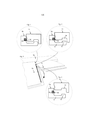
[0034] Um método de instalação de "dobrar" conhecido é descrito nas figuras 1-4. O travamento de bordas curtas 1b, 1c ocorre com um movimento do tipo tesoura onde uma lingueta flexível 30 é deslocada para dentro gradualmente de uma borda para a outra borda quando um lado longo de um painel 1c em uma fileira é conectado inclinando para um painel adjacente 1a em uma fileira previamente instalada. Uma aba de encaixe de pressão flexível 33, que na maioria dos casos é feita de uma seção plástica, durante a dobradura é curvada horizontalmente ao longo da junta. Uma parte da aba de encaixe durante a dobradura é pressionada para dentro, como mostrada na figura 1, e outras partes estão em contato com a borda adjacente, figura 2, ou em uma posição completamente destravada, como mostrada na figura 4. O travamento horizontal ocorre quando um elemento de travamento 8 localizado em uma tira 6 em um primeiro painel 1b, depois aqui referido como um painel de tira, coopera com um segundo painel adjacente 1c, depois aqui referido como um painel de dobra, tal que o elemento de travamento 8 é inserido em uma ranhura de travamento 14.[0034] A known "folding" installation method is described in figures 1-4. Locking of
[0035] As figuras 5a e 5b mostram que a lingueta flexível 30 pode ser conectada a uma borda do painel de dobra 1c ou o painel de tira 1b.[0035] Figures 5a and 5b show that the
[0036] A partir de uma perspectiva de produção é uma vantagem se a lingueta flexível 30 é conectada a um painel de dobra 1c porque é fácil inserir tal uma lingueta flexível em uma ranhura de retenção 32. Não existe tira projetada 6 e a inserção da lingueta flexível pode ser feita com um equipamento de inserção compreendendo dispositivos de guia bastante simples que guiam a lingueta dentro da ranhura de retenção 32. Um problema com tal lingueta flexível 30, como mostrado na figura 5a, é que o sistema de travamento é difícil de travar, na medida em que a aba de encaixe deve ser pressionada para dentro por uma borda superior afiada.[0036] From a production perspective it is an advantage if the
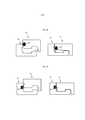
[0037] As figuras 6a-6c mostram uma modalidade da invenção. Um painel de tira 1b compreendendo uma tira 6 e um elemento de travamento 8 que coopera com uma ranhura de travamento 14 em um painel de dobra 1c para travamento horizontal de duas bordas adjacentes do painel de dobra 1c e o painel de tira 1b é fornecido. O painel de tira compreende uma lingueta projetada 10 com uma superfície de guia inclinada ou arredondada 11 e uma superfície de travamento inferior 12. O painel de dobra 1c compreende uma lingueta flexível 30 em uma ranhura de retenção 32, que é aberto para o plano vertical VP. A lingueta flexível 30 tem uma parte interna 34 conectada na ranhura de retenção 32 e uma aba de encaixe flexível 33 com uma superfície deslizante 35 se estendendo para fora e para cima. A superfície deslizante 35, que de preferência está localizada em uma parte superior da aba de encaixe flexível, coopera com a superfície de guia 11 durante um deslocamento vertical do painel de dobra 6c e causa uma força de pressão que curva a aba de encaixe flexível 33 para dentro na direção da ranhura de retenção 32 como mostrado nas figuras 6a- 6b. A aba de encaixe 33 encaixa por pressão de volta para sua posição inicial e dentro da cavidade 31 quando as bordas 1b, 1c são alinhadas horizontalmente e a superfície de travamento inferior 12 na parte inferior da lingueta projetada 10 trava contra a parte superior da aba de encaixe 33 como mostrado na figura 6c. A aba de encaixe flexível 33 e a lingueta projetada 10 travam as bordas verticalmente paralelas ao plano vertical VP. O elemento de travamento 8 e a ranhura de travamento 14 travam as bordas em uma direção horizontal perpendicular ao plano vertical VP. A tira 6 e a lingueta projetada 10 formam uma cavidade 31 que no estado conectado acomoda uma parte externa da aba de encaixe flexível 33. A lingueta projetada é de preferência disposta acima da tira, no plano vertical e se estende a partir do plano vertical. A superfície de travamento da lingueta projetada é de preferência disposta acima da tira.[0037] Figures 6a-6c show an embodiment of the invention. A
[0038] A superfície de guia inclinada 11 facilita um travamento fácil na medida em que o encaixe flexível pode não estar em contato durante o travamento com a borda afiada superior da superfície de painel. A superfície de guia pode ser usada para facilitar um travamento mesmo no caso em que pode existir um contato durante a dobradura entre a borda superior e a aba de encaixe flexível 11.[0038] The slanted
[0039] A superfície de travamento inferior 12 pode ser inclinada e o travamento pode ser feito com uma pré-tensão de modo que a aba de encaixe 11 na posição travada é pressionada contra uma parte inferior da lingueta projetada 10.[0039] The
[0040] A figura 7a mostra que pode existir um espaço S1 entre a parte superior da lingueta 10 e a borda de painel adjacente. O travamento vertical é realizado com um ponto de contato superior A entre a lingueta projetada 10 e a aba de encaixe flexível 33, e um ponto de contato inferior B entre a tira 6 e uma borda inferior do painel de dobra 1c. A aba de encaixe pode ser flexível ou rígido dependendo do desenho e composição de material. Os materiais de polímero são preferidos e a lingueta flexível pode compreender vários materiais diferentes, por exemplo, na parte interna ou na aba de encaixe. A lingueta flexível 30 pode compreender uma junta de joelho 36 com flexibilidade aumentada que facilita a curvatura e/ou deslocamento da aba de encaixe. A ranhura de travamento 14 e a ranhura de retenção 32 são de preferência deslocadas horizontalmente, a fim de obter um sistema de travamento forte, e de preferência com uma distância D1 que é pelo menos 30% da espessura de piso T. A parte superior da ranhura de travamento 14 e a parte interna da ranhura de retenção 32 são de preferência também deslocadas verticalmente com uma distância D2.[0040] Figure 7a shows that there may be a space S1 between the upper part of the
[0041] A figura 7b mostra que pode existir um espaço S2 entre a parte superior da tira 6 e a borda inferior do painel de dobra adjacente 1c. O travamento vertical, nesta modalidade, é realizado com um ponto de contato inferior B entre a lingueta projetada 10 e a aba de encaixe flexível 33, e um ponto de contato superior A entre uma lingueta projetada 10 e uma parte superior do painel de dobra 1c que sobrepõe a lingueta projetada.[0041] Figure 7b shows that there may be a space S2 between the upper part of the
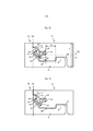
[0042] A figura 8a mostra uma modalidade onde as bordas superiores dos painéis estão em contato uma com a outra e a superfície de guia 11 se estende descendentemente da superfície de painel. A junta de joelho 36 compreende um material flexível 37 que é mais macio que a parte interna 34 e a aba de encaixe 33. A lingueta flexível 30 compreende uma parte interna 34 que compreende uma parte inferior 34a localizada sob a aba de encaixe flexível 33.[0042] Figure 8a shows a mode where the upper edges of the panels are in contact with each other and the
[0043] A figura 8B mostra uma modalidade onde a ranhura de retenção 32 compreende cola 38 e a lingueta flexível 30 é colada na ranhura de retenção. Isto fornece um sistema de travamento mais forte e rachaduras C se estendendo primariamente entre a ranhura de retenção 32 e a ranhura de travamento 14 podem ser evitadas. A parte mais baixa da lingueta flexível 30 pode estar localizada essencialmente no mesmo plano horizontal que a parte inferior e externa 39 do painel de dobra 1c. A ranhura de retenção pode compreender uma parede superior e uma parede inferior e uma parede interna se estendendo entre a parede superior e a parede inferior. A cola é de preferência fornecida na parede superior, na inferior e na interna. A lingueta flexível é de preferência colada na parede superior, na inferior e na interna.[0043] Figure 8B shows a mode where the retaining
Claims (11)
Applications Claiming Priority (3)
| Application Number | Priority Date | Filing Date | Title |
|---|---|---|---|
| SE1251322 | 2012-11-22 | ||
| SE1251322-2 | 2012-11-22 | ||
| PCT/SE2013/051374 WO2014081382A1 (en) | 2012-11-22 | 2013-11-21 | Mechanical locking system for floor panels |
Publications (2)
| Publication Number | Publication Date |
|---|---|
| BR112015011235A2 BR112015011235A2 (en) | 2017-07-11 |
| BR112015011235B1 true BR112015011235B1 (en) | 2021-07-20 |
Family
ID=50776416
Family Applications (1)
| Application Number | Title | Priority Date | Filing Date |
|---|---|---|---|
| BR112015011235-8A BR112015011235B1 (en) | 2012-11-22 | 2013-11-21 | MECHANICAL LOCKING SYSTEM FOR FLOOR PANELS |
Country Status (16)
| Country | Link |
|---|---|
| US (2) | US9366036B2 (en) |
| EP (3) | EP2923012B1 (en) |
| JP (1) | JP6313778B2 (en) |
| KR (1) | KR102297443B1 (en) |
| CN (1) | CN104854286B (en) |
| AU (1) | AU2013348454C1 (en) |
| BR (1) | BR112015011235B1 (en) |
| CA (1) | CA2892212C (en) |
| EA (1) | EA028287B1 (en) |
| HR (1) | HRP20192105T1 (en) |
| LT (1) | LT2923012T (en) |
| MX (1) | MX360077B (en) |
| MY (1) | MY170091A (en) |
| PL (1) | PL2923012T3 (en) |
| UA (1) | UA117003C2 (en) |
| WO (1) | WO2014081382A1 (en) |
Families Citing this family (65)
| Publication number | Priority date | Publication date | Assignee | Title |
|---|---|---|---|---|
| KR100972485B1 (en) | 2002-04-03 | 2010-07-26 | 뵈린게 이노베이션 에이비이 | Mechanical locking system for floorboards |
| SI1650375T2 (en) | 2004-10-22 | 2011-04-29 | Vaelinge Innovation Ab | A set of floor panels |
| US7841144B2 (en) | 2005-03-30 | 2010-11-30 | Valinge Innovation Ab | Mechanical locking system for panels and method of installing same |
| US7454875B2 (en) | 2004-10-22 | 2008-11-25 | Valinge Aluminium Ab | Mechanical locking system for floor panels |
| US8061104B2 (en) | 2005-05-20 | 2011-11-22 | Valinge Innovation Ab | Mechanical locking system for floor panels |
| SE533410C2 (en) | 2006-07-11 | 2010-09-14 | Vaelinge Innovation Ab | Floor panels with mechanical locking systems with a flexible and slidable tongue as well as heavy therefore |
| US11725394B2 (en) | 2006-11-15 | 2023-08-15 | Välinge Innovation AB | Mechanical locking of floor panels with vertical folding |
| US8689512B2 (en) | 2006-11-15 | 2014-04-08 | Valinge Innovation Ab | Mechanical locking of floor panels with vertical folding |
| SE531111C2 (en) | 2006-12-08 | 2008-12-23 | Vaelinge Innovation Ab | Mechanical locking of floor panels |
| US8353140B2 (en) | 2007-11-07 | 2013-01-15 | Valinge Innovation Ab | Mechanical locking of floor panels with vertical snap folding |
| WO2009061279A1 (en) | 2007-11-07 | 2009-05-14 | Välinge Innovation AB | Mechanical locking of floor panels with vertical snap folding and an installation method to connect such panels |
| BRPI0906645B1 (en) | 2008-01-31 | 2021-01-12 | Välinge Innovation AB | set of floor panels with a locking system |
| RU2524091C2 (en) | 2009-01-30 | 2014-07-27 | Велинге Инновейшн Аб, Se | Mechanical locks of floor panels and blank of tongues |
| PL2524093T3 (en) | 2010-01-12 | 2020-07-27 | Välinge Innovation AB | Mechanical locking system for floor panels |
| WO2011096879A1 (en) | 2010-02-04 | 2011-08-11 | Välinge Innovation AB | Mechanical locking system for floor panels and a tongue therefore |
| US8806832B2 (en) | 2011-03-18 | 2014-08-19 | Inotec Global Limited | Vertical joint system and associated surface covering system |
| UA114715C2 (en) | 2011-07-05 | 2017-07-25 | Сералок Інновейшн Аб | Mechanical locking of floor panels with a glued tongue |
| US9725912B2 (en) | 2011-07-11 | 2017-08-08 | Ceraloc Innovation Ab | Mechanical locking system for floor panels |
| US8650826B2 (en) | 2011-07-19 | 2014-02-18 | Valinge Flooring Technology Ab | Mechanical locking system for floor panels |
| US8857126B2 (en) | 2011-08-15 | 2014-10-14 | Valinge Flooring Technology Ab | Mechanical locking system for floor panels |
| US8596013B2 (en) | 2012-04-04 | 2013-12-03 | Valinge Innovation Ab | Building panel with a mechanical locking system |
| US9216541B2 (en) | 2012-04-04 | 2015-12-22 | Valinge Innovation Ab | Method for producing a mechanical locking system for building panels |
| MY170091A (en) | 2012-11-22 | 2019-07-04 | Ceraloc Innovation Ab | Mechanical locking system for floor panels |
| US9194134B2 (en) | 2013-03-08 | 2015-11-24 | Valinge Innovation Ab | Building panels provided with a mechanical locking system |
| US10017948B2 (en) | 2013-06-27 | 2018-07-10 | Valinge Innovation Ab | Building panel with a mechanical locking system |
| CN110453881B (en) | 2014-05-14 | 2021-07-13 | 瓦林格创新股份有限公司 | Building panel with mechanical locking system |
| US10246883B2 (en) | 2014-05-14 | 2019-04-02 | Valinge Innovation Ab | Building panel with a mechanical locking system |
| EP3594429B1 (en) | 2014-11-27 | 2021-04-21 | Välinge Innovation AB | Set of essentially identical floor panels with mechanical locking system |
| WO2016105266A1 (en) | 2014-12-22 | 2016-06-30 | Ceraloc Innovation Ab | Mechanical locking system for floor panels |
| WO2016114712A1 (en) | 2015-01-16 | 2016-07-21 | Ceraloc Innovation Ab | Mechanical locking system for floor panels |
| DE202015101572U1 (en) * | 2015-03-27 | 2015-04-21 | Guido Schulte | Coating of composite rectangular or square panels |
| WO2017060419A1 (en) * | 2015-10-08 | 2017-04-13 | Berryalloc Nv | Set of panels for floor, wall or ceiling covering |
| EP3478903B1 (en) | 2016-06-29 | 2021-09-01 | Välinge Innovation AB | A method and device for managing and separating a tongue from a tongue blank |
| EP3478902B1 (en) | 2016-06-29 | 2021-02-24 | Välinge Innovation AB | Method and device for inserting a tongue |
| JP6935431B2 (en) | 2016-06-29 | 2021-09-15 | ベーリンゲ、イノベイション、アクチボラグVaelinge Innovation Ab | Tongue insertion method and device |
| WO2018004435A1 (en) | 2016-06-30 | 2018-01-04 | Välinge Innovation AB | Device for inserting a tongue |
| DK3558609T3 (en) | 2016-12-22 | 2022-01-03 | Vaelinge Innovation Ab | DEVICE FOR INSERTING A FER IN AN INSERTING NOTICE IN A PANEL |
| USD945870S1 (en) | 2020-11-17 | 2022-03-15 | National Nail Corp. | Fastener positioning device |
| US20210277668A1 (en) | 2017-08-15 | 2021-09-09 | National Nail Corp. | Hidden fastener unit and related method of use |
| USD1019365S1 (en) | 2023-05-31 | 2024-03-26 | National Nail Corp. | Fastener positioning device |
| USD924044S1 (en) | 2019-11-20 | 2021-07-06 | National Nail Corp. | Fastener positioning device |
| US11149445B2 (en) | 2017-08-15 | 2021-10-19 | National Nail Corp. | Hidden fastener unit and related method of use |
| US11898357B2 (en) | 2017-08-15 | 2024-02-13 | National Nail Corp. | Hidden fastener unit and related method of use |
| US11111679B2 (en) | 2017-08-15 | 2021-09-07 | National Nail Corp. | Hidden fastener unit and related method of use |
| USD853829S1 (en) | 2018-06-01 | 2019-07-16 | National Nail Corp. | Fastener positioning device |
| US10378218B2 (en) | 2017-08-15 | 2019-08-13 | National Nail Corp. | Hidden fastener unit and related method of use |
| USD850897S1 (en) | 2018-05-18 | 2019-06-11 | National Nail Corp. | Fastener positioning device |
| US11261893B2 (en) | 2017-08-15 | 2022-03-01 | National Nail Corp. | Hidden fastener unit and related method of use |
| NO20172047A1 (en) * | 2017-12-24 | 2019-06-25 | Humeneq As | The invention relates to a click arrangement for countertop and other plate joints. |
| USD850898S1 (en) | 2019-01-07 | 2019-06-11 | National Nail Corp. | Fastener positioning device |
| US11060302B2 (en) | 2019-01-10 | 2021-07-13 | Valinge Innovation Ab | Unlocking system for panels |
| BE1027032B1 (en) * | 2019-02-07 | 2020-09-07 | Flooring Ind Ltd Sarl | Panel and trim formed with such panels |
| CA186277S (en) * | 2019-02-28 | 2020-06-17 | Carter Arch Panels Inc | Architectural panel perimeter extrusion |
| EP3718437A1 (en) | 2019-04-05 | 2020-10-07 | Välinge Innovation AB | Method for assembling a piece of furniture |
| EP3798386A1 (en) | 2019-09-24 | 2021-03-31 | Välinge Innovation AB | Set of panels with mechanically locking edges |
| CN114466961A (en) | 2019-09-25 | 2022-05-10 | 瓦林格创新股份有限公司 | Set of panels comprising flexible grooves |
| US11479976B2 (en) | 2019-09-25 | 2022-10-25 | Valinge Innovation Ab | Panel with locking device |
| AU2020356521A1 (en) | 2019-09-25 | 2022-03-24 | Välinge Innovation AB | Panel with locking device |
| WO2021246945A1 (en) * | 2020-06-05 | 2021-12-09 | Välinge Innovation AB | Building panels comprising a locking device |
| EP3971364A1 (en) * | 2020-09-17 | 2022-03-23 | Surface Technologies GmbH & Co. KG | Panel |
| US11731252B2 (en) | 2021-01-29 | 2023-08-22 | National Nail Corp. | Screw guide and related method of use |
| US20220243482A1 (en) * | 2021-02-03 | 2022-08-04 | Välinge Innovation AB | Building panels comprising a locking device |
| WO2022197234A1 (en) | 2021-03-19 | 2022-09-22 | Välinge Innovation AB | Building panel with a mechanical locking system |
| DE202021003901U1 (en) * | 2021-12-30 | 2022-02-09 | Surface Technologies Gmbh & Co. Kg | Set of two panels to cover a surface and a panel connector, panel connector and use of a panel connector |
| USD1022684S1 (en) | 2023-02-23 | 2024-04-16 | National Nail Corp. | Fastener positioning device |
Family Cites Families (378)
| Publication number | Priority date | Publication date | Assignee | Title |
|---|---|---|---|---|
| US87853A (en) | 1869-03-16 | Improved mosaic floor | ||
| US124228A (en) | 1872-03-05 | Improvement in skate-fastenings | ||
| US316176A (en) | 1885-04-21 | Fbank h | ||
| US2732706A (en) | 1956-01-31 | Friedman | ||
| US1194636A (en) | 1916-08-15 | Silent door latch | ||
| US108068A (en) | 1870-10-04 | Improvement in tiles for roofing | ||
| US213740A (en) | 1879-04-01 | Improvement in wooden roofs | ||
| US274354A (en) | 1883-03-20 | Carthy | ||
| US634581A (en) | 1898-11-21 | 1899-10-10 | Robert H Miller | Carpenter's square. |
| US861911A (en) | 1905-11-04 | 1907-07-30 | William Stewart | Joint for articles of furniture or woodwork. |
| SE57493C1 (en) | 1923-10-01 | 1924-09-16 | ||
| US1723306A (en) | 1927-08-02 | 1929-08-06 | Harry E Sipe | Resilient attaching strip |
| US1743492A (en) | 1927-08-02 | 1930-01-14 | Harry E Sipe | Resilient plug, dowel, and coupling pin |
| US1809393A (en) | 1929-05-09 | 1931-06-09 | Byrd C Rockwell | Inlay floor construction |
| GB376352A (en) | 1931-04-10 | 1932-07-11 | Charles Harry Hart | Improvements in or relating to wood block floors |
| US1902716A (en) | 1931-09-08 | 1933-03-21 | Midland Creosoting Company | Flooring |
| US2026511A (en) | 1934-05-14 | 1935-12-31 | Storm George Freeman | Floor and process of laying the same |
| US2204675A (en) | 1937-09-29 | 1940-06-18 | Frank A Grunert | Flooring |
| US2266464A (en) | 1939-02-14 | 1941-12-16 | Gen Tire & Rubber Co | Yieldingly joined flooring |
| US2277758A (en) | 1941-08-28 | 1942-03-31 | Frank J Hawkins | Shield |
| US2430200A (en) | 1944-11-18 | 1947-11-04 | Nina Mae Wilson | Lock joint |
| US2596280A (en) | 1947-03-21 | 1952-05-13 | Standard Railway Equipment Mfg | Metal covered walls |
| US2740167A (en) | 1952-09-05 | 1956-04-03 | John C Rowley | Interlocking parquet block |
| US2863185A (en) | 1954-02-16 | 1958-12-09 | Arnold T Riedi | Joint construction including a fastener for securing two structural members together in edge-to-edge closely abutting relation |
| US2858584A (en) | 1954-11-03 | 1958-11-04 | Eugene F Gaines | Spline for hanging tile |
| US2865058A (en) | 1955-04-12 | 1958-12-23 | Gustaf Kahr | Composite floors |
| US2889016A (en) | 1955-04-13 | 1959-06-02 | Warren Jack | Chassis construction strip and a chassis |
| FR1138595A (en) | 1955-12-15 | 1957-06-17 | Tool for working with wooden heel blanks | |
| US3099110A (en) | 1957-09-17 | 1963-07-30 | Dur O Wal National Inc | Control joint |
| US3023681A (en) | 1958-04-21 | 1962-03-06 | Edoco Technical Products | Combined weakened plane joint former and waterstop |
| US3077703A (en) | 1959-04-17 | 1963-02-19 | Wood Conversion Co | Roof deck structure |
| US3147522A (en) | 1960-06-01 | 1964-09-08 | Schumm Erich | Flexible tie |
| CH426190A (en) | 1963-12-23 | 1966-12-15 | Vilin Vertrieb Vissing & Linsm | Fixing device for wall and ceiling cladding |
| US3271787A (en) | 1964-04-06 | 1966-09-13 | Arthur L Clary | Resilient swimming pool coping |
| US3325585A (en) | 1966-03-15 | 1967-06-13 | John H Brenneman | Combined panel fastener and electrical conduit |
| US3396640A (en) | 1966-04-25 | 1968-08-13 | Grace W R & Co | Joint sealing devices |
| US3378958A (en) | 1966-09-21 | 1968-04-23 | Goodrich Co B F | Extrusions having integral portions of different stiffness |
| GB1171337A (en) | 1967-01-28 | 1969-11-19 | Transitoria Trading Company Ab | A Latching Means for Cupboard Doors, Locker Doors, Drawers and like Openable Members |
| US3512324A (en) | 1968-04-22 | 1970-05-19 | Lola L Reed | Portable sectional floor |
| US4037377A (en) | 1968-05-28 | 1977-07-26 | H. H. Robertson Company | Foamed-in-place double-skin building panel |
| US3517927A (en) | 1968-07-24 | 1970-06-30 | William Kennel | Helical spring bouncing device |
| US3572224A (en) | 1968-10-14 | 1971-03-23 | Kaiser Aluminium Chem Corp | Load supporting plank system |
| US3579941A (en) | 1968-11-19 | 1971-05-25 | Howard C Tibbals | Wood parquet block flooring unit |
| US3526071A (en) | 1969-02-17 | 1970-09-01 | Kogyo Gomu Co Ltd | Panel for curtain walls and method of jointing corners of the same |
| SE0001325L (en) | 2000-04-10 | 2001-06-25 | Valinge Aluminium Ab | Locking systems for joining floorboards and floorboards provided with such locking systems and floors formed from such floorboards |
| SE0002342L (en) | 2000-06-22 | 2001-07-16 | Tarkett Sommer Ab | Floor board with connecting means |
| US3760547A (en) | 1969-08-13 | 1973-09-25 | J Brenneman | Spline and seat connector assemblies |
| US3535844A (en) | 1969-10-30 | 1970-10-27 | Glaros Products Inc | Structural panels |
| NL7102276A (en) | 1970-02-20 | 1971-08-24 | ||
| DE2021503A1 (en) | 1970-05-02 | 1971-11-25 | Freudenberg Carl Fa | Floor panels and methods of joining them |
| US3722379A (en) | 1970-09-19 | 1973-03-27 | Mauer F Soehne | Method of constructing an expansion gap device and lost casing for such expansion gap |
| DE2111324C3 (en) | 1971-03-10 | 1979-07-05 | Migua-Mitteldeutsche Gummi Und Asbestgesellschaft Hammerschmidt & Co, 5628 Heiligenhaus | Device for sealing joints between components |
| GB1398709A (en) | 1971-07-12 | 1975-06-25 | Bpb Industries Ltd | Building panel |
| US3760548A (en) | 1971-10-14 | 1973-09-25 | Armco Steel Corp | Building panel with adjustable telescoping interlocking joints |
| DE2159042C3 (en) | 1971-11-29 | 1974-04-18 | Heinrich 6700 Ludwigshafen Hebgen | Insulating board, in particular made of rigid plastic foam |
| US3778954A (en) | 1972-09-07 | 1973-12-18 | Johns Manville | Method of replacing a damaged bulkhead panel |
| US3919820A (en) | 1973-12-13 | 1975-11-18 | Johns Manville | Wall structure and device for sealing thereof |
| FR2256807A1 (en) | 1974-01-07 | 1975-08-01 | Merzeau Jean Alain | Woodworking tool forming slots - has multiple sets of toothed rotary cutters and spacers altered to vary spacing of slots |
| CA1012731A (en) | 1974-08-30 | 1977-06-28 | Beaconfield Consulting Services Limited | Attaching means for members at an angle to one another |
| AT341738B (en) | 1974-12-24 | 1978-02-27 | Hoesch Werke Ag | CONNECTING ELEMENT WITH SLOT AND SPRING CONNECTION |
| AR207658A1 (en) | 1975-07-15 | 1976-10-22 | Gen Tire & Rubber Co | REINFORCED ELASTOMERIC SEAL AND A METHOD OF MANUFACTURING IT |
| US4080086A (en) | 1975-09-24 | 1978-03-21 | Watson-Bowman Associates, Inc. | Roadway joint-sealing apparatus |
| US3994609A (en) | 1975-11-06 | 1976-11-30 | Acme Highway Products Corporation | Elastomeric expansion seal |
| GB1572696A (en) | 1975-11-22 | 1980-07-30 | Vredestein Nv | Injection-sealable water-stop and method of installing same |
| US4007994A (en) | 1975-12-18 | 1977-02-15 | The D. S. Brown Company | Expansion joint with elastomer seal |
| US4169688A (en) | 1976-03-15 | 1979-10-02 | Sato Toshio | Artificial skating-rink floor |
| USRE30154E (en) | 1976-09-02 | 1979-11-20 | Bose Corporation | Joining |
| US4064571A (en) | 1976-09-13 | 1977-12-27 | Timerax Holdings Ltd. | Pool liner retainer |
| US4082129A (en) | 1976-10-20 | 1978-04-04 | Morelock Donald L | Method and apparatus for shaping and planing boards |
| US4104840A (en) | 1977-01-10 | 1978-08-08 | Inryco, Inc. | Metal building panel |
| US4113399A (en) | 1977-03-02 | 1978-09-12 | Hansen Sr Wray C | Knob spring |
| US4107892A (en) | 1977-07-27 | 1978-08-22 | Butler Manufacturing Company | Wall panel unit |
| ES230786Y (en) | 1977-08-27 | 1978-03-16 | GASKET FOR ROOF PANELS. | |
| DE2828769A1 (en) | 1978-06-30 | 1980-01-03 | Oltmanns Heinrich Fa | BOX-SHAPED BUILDING BOARD MADE OF EXTRUDED PLASTIC |
| SE407174B (en) | 1978-06-30 | 1979-03-19 | Bahco Verktyg Ab | TURNING HAND TOOLS WITH SHAFT HALL ROOM FOR STORAGE OF TOOL ELEMENT |
| EP0013852A1 (en) | 1979-01-25 | 1980-08-06 | Claude Delfolie | Door consisting of slightly elastically deformable plastic profile members |
| US4426820A (en) | 1979-04-24 | 1984-01-24 | Heinz Terbrack | Panel for a composite surface and a method of assembling same |
| GB2051916A (en) | 1979-05-02 | 1981-01-21 | Ludford D | Structural Panels, Connectors Therefor and a Structure Erected Therefrom |
| US4304083A (en) | 1979-10-23 | 1981-12-08 | H. H. Robertson Company | Anchor element for panel joint |
| US4447172A (en) | 1982-03-18 | 1984-05-08 | Structural Accessories, Inc. | Roadway expansion joint and seal |
| DK149498C (en) | 1983-04-07 | 1986-12-01 | Inter Ikea As | CLOTHING OF BREADS FOR EX. FLOORS OR PANELS |
| US4512131A (en) | 1983-10-03 | 1985-04-23 | Laramore Larry W | Plank-type building system |
| DE3343601A1 (en) | 1983-12-02 | 1985-06-13 | Bütec Gesellschaft für bühnentechnische Einrichtungen mbH, 4010 Hilden | Joining arrangement for rectangular boards |
| US4648165A (en) | 1984-11-09 | 1987-03-10 | Whitehorne Gary R | Metal frame (spring puller) |
| US4819932A (en) | 1986-02-28 | 1989-04-11 | Trotter Jr Phil | Aerobic exercise floor system |
| US5373674A (en) | 1987-04-27 | 1994-12-20 | Winter, Iv; Amos G. | Prefabricated building panel |
| US5135597A (en) | 1988-06-23 | 1992-08-04 | Weyerhaeuser Company | Process for remanufacturing wood boards |
| US5007222A (en) | 1988-11-14 | 1991-04-16 | Raymond Harry W | Foamed building panel including an internally mounted stud |
| US5071282A (en) | 1988-11-17 | 1991-12-10 | The D. S. Brown Company, Inc. | Highway expansion joint strip seal |
| US5247773A (en) | 1988-11-23 | 1993-09-28 | Weir Richard L | Building structures |
| US5148850A (en) | 1989-06-28 | 1992-09-22 | Paneltech Ltd. | Weatherproof continuous hinge connector for articulated vehicular overhead doors |
| DE3923427A1 (en) | 1989-07-15 | 1991-01-24 | Clouth Gummiwerke Ag | BODY SOUND INSULATING MAT |
| JPH03110258A (en) | 1989-09-25 | 1991-05-10 | Matsushita Electric Works Ltd | Structure of access floor |
| DE3932980A1 (en) | 1989-10-03 | 1991-11-28 | Hoelscher & Leuschner Gmbh | Plastic panels for emergency shelters - form walls, floors, roofs with edge grooves having recesses linked by separate barbed PVC connectors |
| US5026112A (en) | 1990-06-21 | 1991-06-25 | James S. Waldron | Truck trailer with removable side panels |
| US5348778A (en) | 1991-04-12 | 1994-09-20 | Bayer Aktiengesellschaft | Sandwich elements in the form of slabs, shells and the like |
| US5272850A (en) | 1991-05-06 | 1993-12-28 | Icon, Incorporated | Panel connector |
| JPH0518028A (en) | 1991-07-15 | 1993-01-26 | Inax Corp | Coupling method for wall panel |
| US5182892A (en) | 1991-08-15 | 1993-02-02 | Louisiana-Pacific Corporation | Tongue and groove board product |
| US5344700A (en) | 1992-03-27 | 1994-09-06 | Aliquot, Ltd. | Structural panels and joint connector arrangement therefor |
| DE4215273C2 (en) | 1992-05-09 | 1996-01-25 | Dietmar Groeger | Covering for covering floor, wall and / or ceiling surfaces, in particular in the manner of a belt floor |
| US5634309A (en) | 1992-05-14 | 1997-06-03 | Polen; Rodney C. | Portable dance floor |
| US5295341A (en) | 1992-07-10 | 1994-03-22 | Nikken Seattle, Inc. | Snap-together flooring system |
| JP2550466B2 (en) | 1992-11-02 | 1996-11-06 | 大建工業株式会社 | Floor material |
| DE4242530C2 (en) | 1992-12-16 | 1996-09-12 | Walter Friedl | Building element for walls, ceilings or roofs of buildings |
| US5274979A (en) | 1992-12-22 | 1994-01-04 | Tsai Jui Hsing | Insulating plate unit |
| JP3060082B2 (en) | 1993-03-31 | 2000-07-04 | 西川ゴム工業株式会社 | Vibrantly colored architectural gaskets |
| JP2884993B2 (en) | 1993-04-23 | 1999-04-19 | 豊田合成株式会社 | Sealing material for wall panels |
| SE9301595L (en) | 1993-05-10 | 1994-10-17 | Tony Pervan | Grout for thin liquid hard floors |
| US7121059B2 (en) | 1994-04-29 | 2006-10-17 | Valinge Innovation Ab | System for joining building panels |
| US7775007B2 (en) | 1993-05-10 | 2010-08-17 | Valinge Innovation Ab | System for joining building panels |
| JPH06322848A (en) | 1993-05-11 | 1994-11-22 | Sekisui Chem Co Ltd | Waterproof structure of vertical outer wall joint |
| JPH0748879A (en) | 1993-08-05 | 1995-02-21 | Takeshige Shimonohara | Connecting method and connecting structure for member |
| US5598682A (en) | 1994-03-15 | 1997-02-04 | Haughian Sales Ltd. | Pipe retaining clip and method for installing radiant heat flooring |
| US5485702A (en) | 1994-03-25 | 1996-01-23 | Glenn Sholton | Mortarless glass block assembly |
| JP3461569B2 (en) | 1994-05-02 | 2003-10-27 | 大建工業株式会社 | Floor material |
| US5465546A (en) | 1994-05-04 | 1995-11-14 | Buse; Dale C. | Portable dance floor |
| US5502939A (en) | 1994-07-28 | 1996-04-02 | Elite Panel Products | Interlocking panels having flats for increased versatility |
| SE503917C2 (en) | 1995-01-30 | 1996-09-30 | Golvabia Ab | Device for joining by means of groove and chip of adjacent pieces of flooring material and a flooring material composed of a number of smaller pieces |
| US6421970B1 (en) | 1995-03-07 | 2002-07-23 | Perstorp Flooring Ab | Flooring panel or wall panel and use thereof |
| SE9500810D0 (en) | 1995-03-07 | 1995-03-07 | Perstorp Flooring Ab | Floor tile |
| US5618602A (en) | 1995-03-22 | 1997-04-08 | Wilsonart Int Inc | Articles with tongue and groove joint and method of making such a joint |
| US5577357A (en) | 1995-07-10 | 1996-11-26 | Civelli; Ken | Half log siding mounting system |
| JP3331424B2 (en) | 1995-10-31 | 2002-10-07 | ワイケイケイアーキテクチュラルプロダクツ株式会社 | Vertical frame reinforcement structure |
| US5755068A (en) | 1995-11-17 | 1998-05-26 | Ormiston; Fred I. | Veneer panels and method of making |
| BR7502683U (en) | 1995-11-24 | 1996-04-09 | Jacob Abrahams | Constructive arrangements in joints of strips for laminate floors or ceilings |
| US5658086A (en) | 1995-11-24 | 1997-08-19 | Brokaw; Paul E. | Furniture connector |
| JP3954673B2 (en) | 1996-11-01 | 2007-08-08 | 株式会社ヤマックス | Joint for water stop of concrete joints |
| BE1010487A6 (en) | 1996-06-11 | 1998-10-06 | Unilin Beheer Bv | FLOOR COATING CONSISTING OF HARD FLOOR PANELS AND METHOD FOR MANUFACTURING SUCH FLOOR PANELS. |
| US5950389A (en) | 1996-07-02 | 1999-09-14 | Porter; William H. | Splines for joining panels |
| US6203653B1 (en) | 1996-09-18 | 2001-03-20 | Marc A. Seidner | Method of making engineered mouldings |
| US5694730A (en) | 1996-10-25 | 1997-12-09 | Noranda Inc. | Spline for joining boards |
| US6808777B2 (en) | 1996-11-08 | 2004-10-26 | Ab Golvabia | Flooring |
| SE507737C2 (en) | 1996-11-08 | 1998-07-06 | Golvabia Ab | Device for joining of flooring material |
| SE508165C2 (en) | 1996-11-18 | 1998-09-07 | Golvabia Ab | Device for joining of flooring material |
| US5857304A (en) | 1997-04-07 | 1999-01-12 | Abex Display Systems | Slidable locking system for disengageable panels |
| EP0874105B1 (en) | 1997-04-22 | 2004-08-04 | Mondo S.p.A. | A layered flooring, in particular for athletic facilities |
| AT405560B (en) | 1997-06-18 | 1999-09-27 | Kaindl M | ARRANGEMENT OF COMPONENTS AND COMPONENTS |
| IT237576Y1 (en) | 1997-07-11 | 2000-09-13 | Unifor Spa | PERFECTED CONNECTION SYSTEM BETWEEN MODULAR PANELS |
| US6345481B1 (en) | 1997-11-25 | 2002-02-12 | Premark Rwp Holdings, Inc. | Article with interlocking edges and covering product prepared therefrom |
| US6295779B1 (en) | 1997-11-26 | 2001-10-02 | Fred C. Canfield | Composite frame member and method of making the same |
| US5970675A (en) | 1997-12-05 | 1999-10-26 | James D. Wright | Modular panel assembly |
| US6314701B1 (en) | 1998-02-09 | 2001-11-13 | Steven C. Meyerson | Construction panel and method |
| US6173548B1 (en) | 1998-05-20 | 2001-01-16 | Douglas J. Hamar | Portable multi-section activity floor and method of manufacture and installation |
| SE512290C2 (en) | 1998-06-03 | 2000-02-28 | Valinge Aluminium Ab | Locking system for mechanical joining of floorboards and floorboard provided with the locking system |
| SE512313E (en) | 1998-06-03 | 2000-02-28 | Valinge Aluminium Ab | Locking system and floorboard |
| US7386963B2 (en) | 1998-06-03 | 2008-06-17 | Valinge Innovation Ab | Locking system and flooring board |
| BE1012141A6 (en) | 1998-07-24 | 2000-05-02 | Unilin Beheer Bv | FLOOR COVERING, FLOOR PANEL THEREFOR AND METHOD for the realization of such floor panel. |
| SE514645C2 (en) | 1998-10-06 | 2001-03-26 | Perstorp Flooring Ab | Floor covering material comprising disc-shaped floor elements intended to be joined by separate joint profiles |
| SE513189C2 (en) | 1998-10-06 | 2000-07-24 | Perstorp Flooring Ab | Vertically mountable floor covering material comprising sheet-shaped floor elements which are joined together by means of separate joint profiles |
| SE515789C2 (en) | 1999-02-10 | 2001-10-08 | Perstorp Flooring Ab | Floor covering material comprising floor elements which are intended to be joined vertically |
| DE19940837A1 (en) | 1998-10-26 | 2000-11-23 | Karl Boeckl | Floor laying system comprises alignment elements and plate elements with cutouts which are dimensioned so that the alignment elements are easily slidable into their respective cutouts |
| AU2845900A (en) | 1999-01-07 | 2000-08-07 | Aviation Tectonics, Inc. | Fastening, bundling and closure device and dispensing arrangements therefor |
| US6254301B1 (en) | 1999-01-29 | 2001-07-03 | J. Melvon Hatch | Thermoset resin-fiber composites, woodworking dowels and other articles of manufacture made therefrom, and methods |
| DE19911379A1 (en) | 1999-03-15 | 2000-10-12 | Hekuma Herbst Maschinenbau Gmb | Cable ties and method of making cable ties |
| IL129834A (en) | 1999-05-06 | 2001-09-13 | Ackerstein Ind Ltd | Ground surface cover system with flexible interlocking joint for erosion control |
| US6358352B1 (en) | 1999-06-25 | 2002-03-19 | Wyoming Sawmills, Inc. | Method for creating higher grade wood products from lower grade lumber |
| RU2224070C2 (en) | 1999-06-30 | 2004-02-20 | Акцента Панееле + Профиле Гмбх | Plate and attachment system thereof |
| DE29911462U1 (en) | 1999-07-02 | 1999-11-18 | Akzenta Paneele & Profile Gmbh | Fastening system for panels |
| SE517009C2 (en) | 1999-07-05 | 2002-04-02 | Perstorp Flooring Ab | Floor element with controls |
| AT413227B (en) | 1999-07-23 | 2005-12-15 | Kaindl M | PANEL OR LUMINOUS COMPONENTS OR ARRANGEMENT WITH SUCH COMPONENTS AND CLAMPS HIEFÜR |
| US20020194807A1 (en) | 1999-11-08 | 2002-12-26 | Nelson Thomas J. | Multipanel floor system with sealing elements |
| US7614197B2 (en) | 1999-11-08 | 2009-11-10 | Premark Rwp Holdings, Inc. | Laminate flooring |
| US6449918B1 (en) | 1999-11-08 | 2002-09-17 | Premark Rwp Holdings, Inc. | Multipanel floor system panel connector with seal |
| DE29920656U1 (en) | 1999-11-24 | 2000-02-17 | Vincent Irvin G | Universal component |
| DE19958225A1 (en) | 1999-12-03 | 2001-06-07 | Lindner Ag | Locking device for wall, ceiling or floor plates has lock sleeve engaging in bore on fixing part and containing magnetically displaceable element which spreads out sleeve to lock plate until released by magnetic force |
| US7169460B1 (en) | 1999-12-14 | 2007-01-30 | Mannington Mills, Inc. | Thermoplastic planks and methods for making the same |
| US6761008B2 (en) | 1999-12-14 | 2004-07-13 | Mannington Mills, Inc. | Connecting system for surface coverings |
| US6617009B1 (en) | 1999-12-14 | 2003-09-09 | Mannington Mills, Inc. | Thermoplastic planks and methods for making the same |
| AU3334401A (en) | 1999-12-22 | 2001-07-03 | Technique Arts And Design Inc. | Resiliently deformable construction element covering |
| AU4743800A (en) | 1999-12-23 | 2001-07-09 | Hamberger Industriewerke Gmbh | Joint |
| US6332733B1 (en) | 1999-12-23 | 2001-12-25 | Hamberger Industriewerke Gmbh | Joint |
| DE20001788U1 (en) | 2000-02-02 | 2000-06-29 | Kronospan Tech Co Ltd | Panel with plug profile |
| KR100474656B1 (en) | 1999-12-27 | 2005-03-08 | 크로노스판 테크니컬 컴파니 리미티드 | Panel with a shaped plug-in section |
| DE29922649U1 (en) | 1999-12-27 | 2000-03-23 | Kronospan Tech Co Ltd | Panel with plug profile |
| DE10001076C1 (en) | 2000-01-13 | 2001-10-04 | Huelsta Werke Huels Kg | Panel element to construct floor covering; has groove and spring on opposite longitudinal sides and has groove and tongue on opposite end faces, to connect and secure adjacent panel elements |
| EP1120515A1 (en) | 2000-01-27 | 2001-08-01 | Triax N.V. | A combined set comprising a locking member and at least two building panels |
| SE522860C2 (en) | 2000-03-10 | 2004-03-09 | Pergo Europ Ab | Vertically joined floor elements comprising a combination of different floor elements |
| SE518184C2 (en) | 2000-03-31 | 2002-09-03 | Perstorp Flooring Ab | Floor covering material comprising disc-shaped floor elements which are joined together by means of interconnecting means |
| US6363677B1 (en) | 2000-04-10 | 2002-04-02 | Mannington Mills, Inc. | Surface covering system and methods of installing same |
| US6553724B1 (en) | 2000-05-05 | 2003-04-29 | Robert A. Bigler | Panel and trade show booth made therefrom |
| AT411374B (en) | 2000-06-06 | 2003-12-29 | Kaindl M | COATING, COVERING OR THE LIKE, PANELS FOR ITS EDUCATION AND METHOD AND DEVICE FOR PRODUCING THE PANELS |
| FR2810060A1 (en) | 2000-06-08 | 2001-12-14 | Ykk France | Wooden floor paneling, for parquet floor, has elastic strip with lateral flanges forming stop faces for recessed surfaces on panels |
| DE10031639C2 (en) | 2000-06-29 | 2002-08-14 | Hw Ind Gmbh & Co Kg | Floor plate |
| US6339908B1 (en) | 2000-07-21 | 2002-01-22 | Fu-Ming Chuang | Wood floor board assembly |
| US6576079B1 (en) | 2000-09-28 | 2003-06-10 | Richard H. Kai | Wooden tiles and method for making the same |
| US7806624B2 (en) | 2000-09-29 | 2010-10-05 | Tripstop Technologies Pty Ltd | Pavement joint |
| US6455712B1 (en) | 2000-12-13 | 2002-09-24 | Shell Oil Company | Preparation of oxirane compounds |
| US6546691B2 (en) | 2000-12-13 | 2003-04-15 | Kronospan Technical Company Ltd. | Method of laying panels |
| US6851241B2 (en) | 2001-01-12 | 2005-02-08 | Valinge Aluminium Ab | Floorboards and methods for production and installation thereof |
| JP4092202B2 (en) | 2001-01-12 | 2008-05-28 | ベーリンゲ、イノベイション、アクチボラグ | Floorboard and locking system |
| DE10101912C1 (en) | 2001-01-16 | 2002-03-14 | Johannes Schulte | Rectangular floor panel laying method uses fitting wedge for movement of floor panel in longitudinal and transverse directions for interlocking with adjacent floor panel and previous floor panel row |
| CA2331800A1 (en) | 2001-01-22 | 2002-07-22 | Moritz F. Gruber | Portable graphic floor system |
| DE10103505B4 (en) | 2001-01-26 | 2008-06-26 | Pergo (Europe) Ab | Floor or wall panel |
| SE520084C2 (en) | 2001-01-31 | 2003-05-20 | Pergo Europ Ab | Procedure for making merge profiles |
| US6854234B2 (en) | 2001-02-02 | 2005-02-15 | Skyline Displays, Inc. | Panel connector system |
| US6450235B1 (en) | 2001-02-09 | 2002-09-17 | Han-Sen Lee | Efficient, natural slat system |
| AT410815B (en) | 2001-04-05 | 2003-08-25 | Kaindl M | CONNECTION OF PANEL-SHAPED COMPONENTS |
| US20020170259A1 (en) | 2001-05-15 | 2002-11-21 | Ferris Stephen M. | Interlocking sidewalk block system |
| DE20109840U1 (en) | 2001-06-17 | 2001-09-06 | Kronospan Tech Co Ltd | Plates with push-in profile |
| EP1277896A1 (en) | 2001-07-16 | 2003-01-22 | Ulf Palmberg | Floorboards |
| SE519791C2 (en) | 2001-07-27 | 2003-04-08 | Valinge Aluminium Ab | System for forming a joint between two floorboards, floorboards therefore provided with sealing means at the joint edges and ways of manufacturing a core which is processed into floorboards |
| US8028486B2 (en) | 2001-07-27 | 2011-10-04 | Valinge Innovation Ab | Floor panel with sealing means |
| DE10138285A1 (en) | 2001-08-10 | 2003-03-06 | Akzenta Paneele & Profile Gmbh | Panel and fastening system for panels |
| US6684592B2 (en) | 2001-08-13 | 2004-02-03 | Ron Martin | Interlocking floor panels |
| SE525558C2 (en) | 2001-09-20 | 2005-03-08 | Vaelinge Innovation Ab | System for forming a floor covering, set of floorboards and method for manufacturing two different types of floorboards |
| US6651400B1 (en) | 2001-10-18 | 2003-11-25 | Rapid Displays, Inc. | Foam core panel connector |
| FR2831908B1 (en) | 2001-11-02 | 2004-10-22 | Europ De Laquage Et De Faconna | DEVICE FOR ASSEMBLING THE EDGES OF PANELS, SLATS OR PANELS |
| FR2832470B1 (en) | 2001-11-21 | 2006-10-20 | Grosfillex Sarl | PROFILE BLADE DEVICE |
| DE10159284B4 (en) | 2001-12-04 | 2005-04-21 | Kronotec Ag | Building plate, in particular floor panel |
| US7108031B1 (en) | 2002-01-31 | 2006-09-19 | David Secrest | Method of making patterns in wood and decorative articles of wood made from said method |
| DE10206877B4 (en) | 2002-02-18 | 2004-02-05 | E.F.P. Floor Products Fussböden GmbH | Panel, especially floor panel |
| WO2003074814A1 (en) | 2002-03-07 | 2003-09-12 | Fritz Egger Gmbh & Co. | Panels provided with a friction-based fixing |
| KR100972485B1 (en) | 2002-04-03 | 2010-07-26 | 뵈린게 이노베이션 에이비이 | Mechanical locking system for floorboards |
| DE20220655U1 (en) | 2002-04-04 | 2004-01-08 | Akzenta Paneele + Profile Gmbh | Locking system for panels with edge profiles, has groove profile and tongue profile which are engaged to form articulated joint that restores two panels to their installation plane when deflected either up or down |
| EP1350904B2 (en) | 2002-04-05 | 2012-10-24 | tilo GmbH | Floor planks |
| ATE443189T1 (en) | 2002-04-13 | 2009-10-15 | Kronoplus Technical Ag | COVERING SYSTEM, PARTICULARLY FOR A FLOOR, COMPRISING PANELS AND A CORD-LIKE OR ROD-LIKE ELEMENT |
| DE20205774U1 (en) | 2002-04-13 | 2002-08-14 | Kronospan Tech Co Ltd | Panels with rubberized edging |
| US7051486B2 (en) | 2002-04-15 | 2006-05-30 | Valinge Aluminium Ab | Mechanical locking system for floating floor |
| CA2483016C (en) | 2002-04-22 | 2010-08-24 | Valinge Innovation Ab | Floorboards, flooring systems and methods for manufacturing and installation thereof |
| US7739849B2 (en) | 2002-04-22 | 2010-06-22 | Valinge Innovation Ab | Floorboards, flooring systems and methods for manufacturing and installation thereof |
| DE10233731A1 (en) | 2002-07-24 | 2004-04-08 | M. Kaindl | Arrangement of components with connecting elements |
| DE10237397A1 (en) | 2002-08-09 | 2004-02-19 | Profilex Ag | Method for edge joining flat panels has profiled grooves in the adjoining edges gripped by an elastic profile with at least one grip section which cannot be released by external force |
| AT413228B (en) | 2002-08-19 | 2005-12-15 | Kaindl M | COVER PLATE |
| US8375673B2 (en) | 2002-08-26 | 2013-02-19 | John M. Evjen | Method and apparatus for interconnecting paneling |
| US6792727B2 (en) | 2002-09-12 | 2004-09-21 | Commercial And Architectural Products, Inc. | Curved wall panel system |
| DE10243196B4 (en) | 2002-09-18 | 2007-03-22 | Kaindl Flooring Gmbh | Panels with connection bracket |
| US7617651B2 (en) | 2002-11-12 | 2009-11-17 | Kronotec Ag | Floor panel |
| ES2307840T3 (en) | 2002-11-15 | 2008-12-01 | Flooring Technologies Ltd. | EQUIPMENT COMPOSED BY TWO CONSTRUCTION PLATES THAT CAN JOIN BETWEEN YES AND AN INSERTED PIECE TO INTERLOCK THESE CONSTRUCTION PLATES. |
| BE1015223A3 (en) | 2002-11-25 | 2004-11-09 | Flooring Ind Ltd | Floor panel, covering it formed, method for the installation of such floor panels and method for manufacturing same. |
| DE10318093A1 (en) | 2002-12-02 | 2004-06-17 | Kronospan Ag | Process for gluing an element |
| SE525622C2 (en) | 2002-12-09 | 2005-03-22 | Pergo Europ Ab | Procedure for installation of panels with joints, encapsulated agent and glue |
| DE20320022U1 (en) | 2003-01-09 | 2004-04-01 | Flooring Industries Ltd. | Set of floor panels to form a floor covering |
| US7533500B2 (en) | 2003-01-27 | 2009-05-19 | Deceuninck North America, Llc | Deck plank and method of production |
| US6948716B2 (en) | 2003-03-03 | 2005-09-27 | Drouin Gerard | Waterstop having improved water and moisture sealing features |
| EP2412892B1 (en) | 2003-03-06 | 2017-06-07 | Välinge Innovation AB | Flooring systems and methods for installation |
| US7845140B2 (en) | 2003-03-06 | 2010-12-07 | Valinge Innovation Ab | Flooring and method for installation and manufacturing thereof |
| US7677001B2 (en) | 2003-03-06 | 2010-03-16 | Valinge Innovation Ab | Flooring systems and methods for installation |
| AT501440A1 (en) | 2003-03-07 | 2006-09-15 | Kaindl Flooring Gmbh | COVER PLATE |
| EP1601845A1 (en) | 2003-03-07 | 2005-12-07 | Akzo Nobel Coatings International BV | Interlocking unit |
| SE0300642D0 (en) | 2003-03-11 | 2003-03-11 | Pergo Europ Ab | Process for sealing a joint |
| SE526691C2 (en) | 2003-03-18 | 2005-10-25 | Pergo Europ Ab | Panel joint with friction raising means at longitudinal side joint |
| DE10313112B4 (en) | 2003-03-24 | 2007-05-03 | Fritz Egger Gmbh & Co. | Covering with a plurality of panels, in particular floor covering, and method for laying panels |
| DE20304761U1 (en) | 2003-03-24 | 2004-04-08 | Kronotec Ag | Device for connecting building boards, in particular floor panels |
| US7152383B1 (en) | 2003-04-10 | 2006-12-26 | Eps Specialties Ltd., Inc. | Joining of foam core panels |
| DE10329686B4 (en) | 2003-07-02 | 2008-02-28 | Akzenta Paneele + Profile Gmbh | Panel with locking system |
| ES2367634T3 (en) | 2003-07-02 | 2011-11-07 | Interglarion Limited | PLATES WITH INSERTABLE JOINT PROFILE. |
| KR100566083B1 (en) | 2003-08-07 | 2006-03-30 | 주식회사 한솔홈데코 | Sectional floorings |
| DE20313661U1 (en) | 2003-09-05 | 2003-11-13 | Kaindl Wals M | Panel with protected V-groove |
| SE526688C2 (en) | 2003-11-20 | 2005-10-25 | Pergo Europ Ab | Method of joining panels where a locking rod is inserted into a locking groove or locking cavity |
| SE526179C2 (en) | 2003-12-02 | 2005-07-19 | Vaelinge Innovation Ab | Flooring and method of laying |
| US7886497B2 (en) | 2003-12-02 | 2011-02-15 | Valinge Innovation Ab | Floorboard, system and method for forming a flooring, and a flooring formed thereof |
| DE102004001363A1 (en) | 2004-01-07 | 2005-08-04 | Hamberger Industriewerke Gmbh | Floor units interconnection, has panel with interlocking projection having spring blade, which lies in interlocked position with abutting face of active surface of vertical interlocking projection |
| US7516588B2 (en) | 2004-01-13 | 2009-04-14 | Valinge Aluminium Ab | Floor covering and locking systems |
| DE102005002297A1 (en) | 2004-01-16 | 2005-08-04 | Hamberger Industriewerke Gmbh | Tile-shaped building parts e.g. laminated floor tiles, joint, has devices for horizontal and vertical interlocking, which is provided along part`s leading edges formed independent of elasticity of materials with which parts are made |
| DE202004001037U1 (en) | 2004-01-24 | 2004-04-29 | Kronotec Ag | Panel, in particular floor panel |
| DE102004005047B3 (en) | 2004-01-30 | 2005-10-20 | Kronotec Ag | Method and device for introducing a strip forming the spring of a plate |
| US7556849B2 (en) | 2004-03-25 | 2009-07-07 | Johns Manville | Low odor faced insulation assembly |
| US7219392B2 (en) | 2004-06-28 | 2007-05-22 | Wayne-Dalton Corp. | Breakaway track system for an overhead door |
| BE1016216A5 (en) | 2004-09-24 | 2006-05-02 | Flooring Ind Ltd | FLOOR PANEL AND FLOOR COVERING COMPOSED OF SUCH FLOOR PANELS. |
| SI1650375T2 (en) | 2004-10-22 | 2011-04-29 | Vaelinge Innovation Ab | A set of floor panels |
| US7841144B2 (en) | 2005-03-30 | 2010-11-30 | Valinge Innovation Ab | Mechanical locking system for panels and method of installing same |
| US7454875B2 (en) | 2004-10-22 | 2008-11-25 | Valinge Aluminium Ab | Mechanical locking system for floor panels |
| DE102004054368A1 (en) | 2004-11-10 | 2006-05-11 | Kaindl Flooring Gmbh | trim panel |
| US20060174577A1 (en) | 2005-01-27 | 2006-08-10 | O'neil John P | Hidden stiffening panel connector and connecting method |
| US20060179754A1 (en) | 2005-02-02 | 2006-08-17 | Feng-Ling Yang | Combinable floor plate |
| US8061104B2 (en) | 2005-05-20 | 2011-11-22 | Valinge Innovation Ab | Mechanical locking system for floor panels |
| DE102005024366A1 (en) | 2005-05-27 | 2006-11-30 | Kaindl Flooring Gmbh | Method for laying and mechanically connecting panels |
| SE529076C2 (en) | 2005-07-11 | 2007-04-24 | Pergo Europ Ab | A joint for panels |
| CA2618496C (en) | 2005-08-16 | 2010-02-09 | Johannes Schulte | Method for production of panels |
| DE102005038975B3 (en) | 2005-08-16 | 2006-12-14 | Johannes Schulte | Panel production process for floor, wall or ceiling panels has initial board with parallel grooves in upper and lower surfaces |
| DE102005054725A1 (en) | 2005-11-17 | 2007-05-24 | Agro Federkernproduktions Gmbh | innerspring |
| US20070151189A1 (en) | 2006-01-03 | 2007-07-05 | Feng-Ling Yang | Securing device for combining floor plates |
| US8464489B2 (en) | 2006-01-12 | 2013-06-18 | Valinge Innovation Ab | Laminate floor panels |
| SE530653C2 (en) | 2006-01-12 | 2008-07-29 | Vaelinge Innovation Ab | Moisture-proof floor board and floor with an elastic surface layer including a decorative groove |
| DE102006011887A1 (en) * | 2006-01-13 | 2007-07-19 | Akzenta Paneele + Profile Gmbh | Blocking element, panel with separate blocking element, method of installing a panel covering of panels with blocking elements, and method and device for pre-assembling a blocking element on a panel |
| SE529506C2 (en) | 2006-02-03 | 2007-08-28 | Pergo Europ Ab | A joint cover for panels |
| CA2576889A1 (en) | 2006-02-06 | 2007-08-06 | Insca Internacional, S.L. | Device for joining parquet-type plaques or pieces |
| DE102006006124A1 (en) | 2006-02-10 | 2007-08-23 | Flooring Technologies Ltd. | Device for locking two building panels |
| US7971327B2 (en) | 2006-03-10 | 2011-07-05 | Mannington Mills, Inc. | Process and system for sub-dividing a laminated flooring substrate |
| DK2009197T3 (en) | 2006-04-14 | 2016-06-13 | Yekalon Ind Inc | Floor block, floor system and laying method therefore |
| DE102006024184A1 (en) | 2006-05-23 | 2007-11-29 | Hipper, August, Dipl.-Ing. (FH) | Connection for panel boards forms a groove/spring connection along edges to be connected so as to fix in a vertical direction |
| BE1017157A3 (en) | 2006-06-02 | 2008-03-04 | Flooring Ind Ltd | FLOOR COVERING, FLOOR ELEMENT AND METHOD FOR MANUFACTURING FLOOR ELEMENTS. |
| SE530048C2 (en) | 2006-06-09 | 2008-02-19 | Burseryd Innovation Ab | Fasteners and method of joining dynamic bodies by means of the fastener |
| SE533410C2 (en) | 2006-07-11 | 2010-09-14 | Vaelinge Innovation Ab | Floor panels with mechanical locking systems with a flexible and slidable tongue as well as heavy therefore |
| US7861482B2 (en) | 2006-07-14 | 2011-01-04 | Valinge Innovation Ab | Locking system comprising a combination lock for panels |
| US7654055B2 (en) | 2006-08-08 | 2010-02-02 | Ricker Michael B | Glueless panel locking system |
| DE102006037614B3 (en) | 2006-08-10 | 2007-12-20 | Guido Schulte | Floor covering, has head spring pre-assembled in slot and protruding over end of slot, and wedge surface formed at slot or head spring such that head spring runs into wedge surface by shifting projecting end of head spring into slot |
| US7257926B1 (en) | 2006-08-24 | 2007-08-21 | Kirby Mark E | Tile spacer and leveler |
| EP2570565B1 (en) | 2006-11-15 | 2018-12-05 | Välinge Innovation AB | Mechanical locking of floor panels with vertical folding |
| US8689512B2 (en) | 2006-11-15 | 2014-04-08 | Valinge Innovation Ab | Mechanical locking of floor panels with vertical folding |
| DE102006057491A1 (en) * | 2006-12-06 | 2008-06-12 | Akzenta Paneele + Profile Gmbh | Panel and flooring |
| SE531111C2 (en) | 2006-12-08 | 2008-12-23 | Vaelinge Innovation Ab | Mechanical locking of floor panels |
| DE202007019282U1 (en) | 2007-02-21 | 2011-09-28 | Hamberger Industriewerke Gmbh | Connection for plate-shaped components |
| SE532207C2 (en) | 2007-03-14 | 2009-11-17 | Kaehr Ab G | Floor-laying system, profile rail and floor-board for such floor-laying system Procedure for laying conduit elements in the floor-laying system as well as uses of the floor-laying system for various purposes |
| DE202007018662U1 (en) | 2007-03-26 | 2009-02-19 | Kronotec Ag | Panel, in particular floor panel |
| DE102007016533A1 (en) | 2007-04-05 | 2008-10-09 | Hülsta-Werke Hüls Gmbh & Co. Kg | Floor, wall or ceiling panels and method for connecting floor, wall or ceiling panels |
| DE102007017087B4 (en) | 2007-04-10 | 2009-06-25 | Kronotec Ag | Panel, in particular floor panel |
| DE102007026342B4 (en) | 2007-06-06 | 2013-11-28 | Laminatepark Gmbh & Co. Kg | Set of tabular panels with movable locking element |
| DE102007032885B4 (en) | 2007-07-14 | 2016-01-14 | Flooring Technologies Ltd. | Panel, in particular floor panel and means for locking interconnected panels |
| US7726088B2 (en) | 2007-07-20 | 2010-06-01 | Moritz Andre Muehlebach | Flooring system |
| US8220217B2 (en) | 2007-07-20 | 2012-07-17 | Innovaris Ag | Flooring system |
| DE102007035648A1 (en) * | 2007-07-27 | 2009-01-29 | Agepan-Tarkett Laminatepark Eiweiler Gmbh & Co. Kg | Board-like panel used as a floor panel comprises a locking element fixed to a holding profile by inserting or sliding |
| DE102007049792A1 (en) | 2007-08-10 | 2009-02-19 | Hamberger Industriewerke Gmbh | connection |
| DE102007042250B4 (en) | 2007-09-06 | 2010-04-22 | Flooring Technologies Ltd. | Device for connecting and locking two building panels, in particular floor panels |
| DE102007043308B4 (en) | 2007-09-11 | 2009-12-03 | Flooring Technologies Ltd. | Device for connecting and locking two building panels, in particular floor panels |
| WO2009061279A1 (en) | 2007-11-07 | 2009-05-14 | Välinge Innovation AB | Mechanical locking of floor panels with vertical snap folding and an installation method to connect such panels |
| US8353140B2 (en) | 2007-11-07 | 2013-01-15 | Valinge Innovation Ab | Mechanical locking of floor panels with vertical snap folding |
| BE1018600A5 (en) | 2007-11-23 | 2011-04-05 | Flooring Ind Ltd Sarl | FLOOR PANEL. |
| US7805903B2 (en) | 2007-12-13 | 2010-10-05 | Liu David C | Locking mechanism for flooring boards |
| DE102008003550B4 (en) | 2008-01-09 | 2009-10-22 | Flooring Technologies Ltd. | Device and method for locking two floor panels |
| US8505257B2 (en) | 2008-01-31 | 2013-08-13 | Valinge Innovation Ab | Mechanical locking of floor panels |
| BRPI0906645B1 (en) | 2008-01-31 | 2021-01-12 | Välinge Innovation AB | set of floor panels with a locking system |
| CA2659034A1 (en) | 2008-03-26 | 2009-09-26 | Charles Beaulieu | Fastening device template |
| WO2009139687A1 (en) | 2008-05-15 | 2009-11-19 | Välinge Innovation AB | Floor panels with a mechanical locking system activated by a magnetic field and a method to install the panels |
| DE102008031167B4 (en) | 2008-07-03 | 2015-07-09 | Flooring Technologies Ltd. | Method for connecting and locking glueless laying floor panels |
| DE102008047099B4 (en) | 2008-09-12 | 2010-05-12 | Guido Schulte | flooring |
| CN102239301A (en) | 2008-10-08 | 2011-11-09 | 阿姆斯特郎世界工业公司 | Flooring panel with first and second decorative surfaces |
| BE1018389A3 (en) | 2008-12-17 | 2010-10-05 | Unilin Bvba | COMPOSITE ELEMENT, MULTI-LAYER PLATE AND PANEL-SHAPED ELEMENT FOR FORMING SUCH COMPOSITE ELEMENT. |
| US7998549B2 (en) | 2009-01-08 | 2011-08-16 | Thermwood Corporation | Structure and method of assembly thereof |
| BE1018627A5 (en) | 2009-01-16 | 2011-05-03 | Flooring Ind Ltd Sarl | FLOOR PANEL. |
| RU2524091C2 (en) | 2009-01-30 | 2014-07-27 | Велинге Инновейшн Аб, Se | Mechanical locks of floor panels and blank of tongues |
| EP2236694A1 (en) | 2009-03-25 | 2010-10-06 | Spanolux N.V.- DIV. Balterio | A fastening system and a panel |
| DE102009022483A1 (en) | 2009-05-25 | 2010-12-02 | Pergo (Europe) Ab | Set of panels, in particular floor panels |
| ATE510088T1 (en) | 2009-06-08 | 2011-06-15 | Flooring Technologies Ltd | SET OF BUILDING PLATES WITH A DEVICE FOR LOCKING TWO OF THESE BUILDING PLATES |
| BE1018802A3 (en) | 2009-06-29 | 2011-09-06 | Flooring Ind Ltd Sarl | PANEL, MORE SPECIAL FLOOR PANEL. |
| TWM373948U (en) | 2009-07-22 | 2010-02-11 | Feng-Ling Yang | Assembly floor |
| DE102009034902B4 (en) * | 2009-07-27 | 2015-10-01 | Guido Schulte | Surface made of mechanically interconnectable panels |
| DE102009034903B3 (en) | 2009-07-27 | 2011-01-20 | Guido Schulte | Surface made of mechanically interconnectable panels |
| US8322104B2 (en) | 2009-08-31 | 2012-12-04 | Fleming Iii Joseph C | Method and system for interconnecting structural panels |
| DE102009041297B4 (en) | 2009-09-15 | 2018-10-11 | Guido Schulte | Coating of mechanically interconnectable elements and a process for the production of elements |
| CN201588375U (en) | 2009-09-29 | 2010-09-22 | 钟玉东 | Embedded type combined solid wood flooring |
| DE102009048050B3 (en) | 2009-10-02 | 2011-01-20 | Guido Schulte | Surface made of mechanical interconnectable elements |
| US8429870B2 (en) | 2009-12-04 | 2013-04-30 | Mannington Mills, Inc. | Connecting system for surface coverings |
| PL2333195T3 (en) | 2009-12-14 | 2014-12-31 | Barlinek Sa | Floor made of floor panels with separate connection components |
| PL2524093T3 (en) | 2010-01-12 | 2020-07-27 | Välinge Innovation AB | Mechanical locking system for floor panels |
| DE102010004717A1 (en) | 2010-01-15 | 2011-07-21 | Pergo (Europe) Ab | Set of panels comprising retaining profiles with a separate clip and method for introducing the clip |
| US8234830B2 (en) | 2010-02-04 | 2012-08-07 | Välinge Innovations AB | Mechanical locking system for floor panels |
| WO2011096879A1 (en) | 2010-02-04 | 2011-08-11 | Välinge Innovation AB | Mechanical locking system for floor panels and a tongue therefore |
| US20110197535A1 (en) | 2010-02-13 | 2011-08-18 | Geoffrey Alan Baker | Laying and mechanically joining building panels or construction elements |
| CN102844506B (en) | 2010-04-15 | 2015-08-12 | 巴尔特利奥-斯巴诺吕克斯股份公司 | Floor panel assembly |
| CN102884260B (en) | 2010-05-10 | 2015-05-13 | 佩尔戈(欧洲)股份公司 | Set of panels |
| BE1019747A3 (en) | 2010-07-15 | 2012-12-04 | Flooring Ind Ltd Sarl | UPHOLSTERY AND PANELS AND ACCESSORIES USED THEREIN. |
| WO2011151758A2 (en) | 2010-06-03 | 2011-12-08 | Unilin, Bvba | Composed element and corner connection applied herewith |
| EP2397623B1 (en) | 2010-06-17 | 2018-01-31 | Unilin, BVBA | A panel coupling assembly |
| CN103180533B (en) | 2010-10-20 | 2016-03-09 | 克诺那普雷斯技术股份公司 | Comprise the surface covering of laminated panel and outside locking member |
| GB2483525B (en) | 2011-02-03 | 2013-05-01 | Oliver James Furniture Ltd | A panel connection system |
| US9322421B2 (en) | 2011-04-13 | 2016-04-26 | Geoffrey Alan Baker | Spring-loaded split-tongue connector system |
| UA109938C2 (en) | 2011-05-06 | 2015-10-26 | MECHANICAL LOCKING SYSTEM FOR CONSTRUCTION PANELS | |
| UA114715C2 (en) | 2011-07-05 | 2017-07-25 | Сералок Інновейшн Аб | Mechanical locking of floor panels with a glued tongue |
| US8631622B2 (en) | 2011-07-07 | 2014-01-21 | Chinafloors Holding Limited | Non-squeaking wood flooring systems and methods |
| US9725912B2 (en) | 2011-07-11 | 2017-08-08 | Ceraloc Innovation Ab | Mechanical locking system for floor panels |
| MY164102A (en) * | 2011-07-19 | 2017-11-30 | Ceraloc Innovation Ab | Mechanical locking system for floor panels |
| US8650826B2 (en) | 2011-07-19 | 2014-02-18 | Valinge Flooring Technology Ab | Mechanical locking system for floor panels |
| DE102012102339A1 (en) | 2011-07-29 | 2013-01-31 | Hamberger Industriewerke Gmbh | Connection for elastic or plate-shaped components, profile slides and floor coverings |
| DE102012105793A1 (en) | 2011-07-29 | 2013-01-31 | Hamberger Industriewerke Gmbh | Connection for elastic or plate-shaped components and floor covering |
| US8769905B2 (en) | 2011-08-15 | 2014-07-08 | Valinge Flooring Technology Ab | Mechanical locking system for floor panels |
| US8857126B2 (en) | 2011-08-15 | 2014-10-14 | Valinge Flooring Technology Ab | Mechanical locking system for floor panels |
| US8763340B2 (en) | 2011-08-15 | 2014-07-01 | Valinge Flooring Technology Ab | Mechanical locking system for floor panels |
| CN103732841B (en) | 2011-08-15 | 2016-09-21 | 塞拉洛克创新股份有限公司 | Mechanical locking system for floor panel |
| KR102197543B1 (en) | 2011-08-29 | 2020-12-31 | 세라록 이노베이션 에이비 | Mechanical locking system for floor panels |
| EP2570564A3 (en) | 2011-09-16 | 2014-08-20 | Spanolux N.V. Div. Balterio | An apparatus and a method for assembling panels and locking elements |
| DE202011108752U1 (en) | 2011-12-06 | 2012-01-24 | Akzenta Paneele + Profile Gmbh | Locking system for panels and panel with locking system |
| DE102011056494A1 (en) | 2011-12-15 | 2013-06-20 | Pergo (Europe) Ab | Set of panels with clip |
| BE1020433A3 (en) | 2012-01-05 | 2013-10-01 | Flooring Ind Ltd Sarl | PANEL. |
| US9394698B2 (en) | 2012-02-23 | 2016-07-19 | Admiral Composite Technologies, Inc. | Deck system and components |
| WO2013151493A1 (en) | 2012-04-04 | 2013-10-10 | Välinge Innovation AB | Method for producing a mechanical locking system for building panels |
| US9216541B2 (en) | 2012-04-04 | 2015-12-22 | Valinge Innovation Ab | Method for producing a mechanical locking system for building panels |
| US8596013B2 (en) | 2012-04-04 | 2013-12-03 | Valinge Innovation Ab | Building panel with a mechanical locking system |
| MY170091A (en) | 2012-11-22 | 2019-07-04 | Ceraloc Innovation Ab | Mechanical locking system for floor panels |
| US9556620B2 (en) | 2013-01-11 | 2017-01-31 | Flooring Industries Limited, Sarl | Floor panel for forming a floor covering, floor covering formed of such floor panels, and method for manufacturing such floor panels |
| US9194134B2 (en) | 2013-03-08 | 2015-11-24 | Valinge Innovation Ab | Building panels provided with a mechanical locking system |
| PT2978909T (en) | 2013-03-25 | 2018-06-18 | Vaelinge Innovation Ab | Floorboards provided with a mechanical locking system and a method to produce such a locking system |
| US10017948B2 (en) | 2013-06-27 | 2018-07-10 | Valinge Innovation Ab | Building panel with a mechanical locking system |
| CN110453881B (en) | 2014-05-14 | 2021-07-13 | 瓦林格创新股份有限公司 | Building panel with mechanical locking system |
| US10246883B2 (en) | 2014-05-14 | 2019-04-02 | Valinge Innovation Ab | Building panel with a mechanical locking system |
| EP3594429B1 (en) | 2014-11-27 | 2021-04-21 | Välinge Innovation AB | Set of essentially identical floor panels with mechanical locking system |
| WO2016105266A1 (en) | 2014-12-22 | 2016-06-30 | Ceraloc Innovation Ab | Mechanical locking system for floor panels |
-
2013
- 2013-11-21 MY MYPI2015001258A patent/MY170091A/en unknown
- 2013-11-21 AU AU2013348454A patent/AU2013348454C1/en active Active
- 2013-11-21 JP JP2015544034A patent/JP6313778B2/en active Active
- 2013-11-21 BR BR112015011235-8A patent/BR112015011235B1/en active IP Right Grant
- 2013-11-21 CN CN201380060795.9A patent/CN104854286B/en active Active
- 2013-11-21 EP EP13857637.6A patent/EP2923012B1/en active Active
- 2013-11-21 EP EP19202892.6A patent/EP3613920B1/en active Active
- 2013-11-21 UA UAA201505761A patent/UA117003C2/en unknown
- 2013-11-21 CA CA2892212A patent/CA2892212C/en active Active
- 2013-11-21 US US14/646,567 patent/US9366036B2/en active Active
- 2013-11-21 WO PCT/SE2013/051374 patent/WO2014081382A1/en active Application Filing
- 2013-11-21 EA EA201590940A patent/EA028287B1/en not_active IP Right Cessation
- 2013-11-21 EP EP24152885.0A patent/EP4375449A2/en active Pending
- 2013-11-21 PL PL13857637T patent/PL2923012T3/en unknown
- 2013-11-21 MX MX2015006451A patent/MX360077B/en active IP Right Grant
- 2013-11-21 KR KR1020157015460A patent/KR102297443B1/en active IP Right Grant
- 2013-11-21 LT LT13857637T patent/LT2923012T/en unknown
-
2016
- 2016-05-20 US US15/160,311 patent/US9771723B2/en active Active
-
2019
- 2019-11-21 HR HRP20192105TT patent/HRP20192105T1/en unknown
Also Published As
| Publication number | Publication date |
|---|---|
| EP2923012A1 (en) | 2015-09-30 |
| JP2016502002A (en) | 2016-01-21 |
| EP3613920C0 (en) | 2024-01-31 |
| EP2923012A4 (en) | 2016-08-17 |
| US9771723B2 (en) | 2017-09-26 |
| MY170091A (en) | 2019-07-04 |
| CN104854286A (en) | 2015-08-19 |
| JP6313778B2 (en) | 2018-04-18 |
| LT2923012T (en) | 2019-11-11 |
| PL2923012T3 (en) | 2020-04-30 |
| EP3613920A1 (en) | 2020-02-26 |
| US9366036B2 (en) | 2016-06-14 |
| KR20150086489A (en) | 2015-07-28 |
| EA201590940A1 (en) | 2015-09-30 |
| UA117003C2 (en) | 2018-06-11 |
| US20160326751A1 (en) | 2016-11-10 |
| AU2013348454C1 (en) | 2017-11-09 |
| AU2013348454A1 (en) | 2015-06-18 |
| CA2892212C (en) | 2020-06-30 |
| EP2923012B1 (en) | 2019-10-16 |
| CA2892212A1 (en) | 2014-05-30 |
| MX2015006451A (en) | 2015-08-14 |
| BR112015011235A2 (en) | 2017-07-11 |
| KR102297443B1 (en) | 2021-09-01 |
| CN104854286B (en) | 2018-04-13 |
| AU2013348454B2 (en) | 2017-07-20 |
| EA028287B1 (en) | 2017-10-31 |
| EP3613920B1 (en) | 2024-01-31 |
| WO2014081382A1 (en) | 2014-05-30 |
| EP4375449A2 (en) | 2024-05-29 |
| MX360077B (en) | 2018-10-19 |
| US20150300029A1 (en) | 2015-10-22 |
| HRP20192105T1 (en) | 2020-02-21 |
Similar Documents
| Publication | Publication Date | Title |
|---|---|---|
| BR112015011235B1 (en) | MECHANICAL LOCKING SYSTEM FOR FLOOR PANELS | |
| US11746536B2 (en) | Building panel with a mechanical locking system | |
| US11428253B2 (en) | Mechanical locking system for building panels | |
| US9453347B2 (en) | Mechanical locking system for floor panels | |
| CA2839681C (en) | Mechanical locking of floor panels with a glued tongue | |
| US9284737B2 (en) | Mechanical locking system for floor panels | |
| JP6139661B2 (en) | Floating floor system, floor panel, and installation method thereof | |
| BR112018012019B1 (en) | FLOOR PANEL TO FORM A FLOOR COVERING | |
| US20040187423A1 (en) | Interconnectable panel for use primarily as flooring | |
| BR112014000516B1 (en) | construction panels provided with mechanical locking system |
Legal Events
| Date | Code | Title | Description |
|---|---|---|---|
| B08F | Application dismissed because of non-payment of annual fees [chapter 8.6 patent gazette] | ||
| B08G | Application fees: restoration [chapter 8.7 patent gazette] | ||
| B25A | Requested transfer of rights approved |
Owner name: CERALOC INNOVATION AB (SE) |
|
| B06F | Objections, documents and/or translations needed after an examination request according [chapter 6.6 patent gazette] | ||
| B06U | Preliminary requirement: requests with searches performed by other patent offices: procedure suspended [chapter 6.21 patent gazette] | ||
| B09A | Decision: intention to grant [chapter 9.1 patent gazette] | ||
| B16A | Patent or certificate of addition of invention granted [chapter 16.1 patent gazette] |
Free format text: PRAZO DE VALIDADE: 20 (VINTE) ANOS CONTADOS A PARTIR DE 21/11/2013, OBSERVADAS AS CONDICOES LEGAIS. |