BR112015001039B1 - system for preparing a drink - Google Patents
system for preparing a drink Download PDFInfo
- Publication number
- BR112015001039B1 BR112015001039B1 BR112015001039-3A BR112015001039A BR112015001039B1 BR 112015001039 B1 BR112015001039 B1 BR 112015001039B1 BR 112015001039 A BR112015001039 A BR 112015001039A BR 112015001039 B1 BR112015001039 B1 BR 112015001039B1
- Authority
- BR
- Brazil
- Prior art keywords
- flange
- capsule
- rim
- edge
- receptacle
- Prior art date
Links
- 239000002775 capsule Substances 0.000 claims abstract description 182
- 238000007789 sealing Methods 0.000 claims abstract description 108
- 238000001802 infusion Methods 0.000 claims abstract description 57
- 230000002093 peripheral effect Effects 0.000 claims description 13
- XLYOFNOQVPJJNP-UHFFFAOYSA-N water Substances O XLYOFNOQVPJJNP-UHFFFAOYSA-N 0.000 description 24
- 239000004033 plastic Substances 0.000 description 13
- 229920003023 plastic Polymers 0.000 description 13
- 235000013361 beverage Nutrition 0.000 description 12
- 230000006835 compression Effects 0.000 description 9
- 238000007906 compression Methods 0.000 description 9
- 229910052751 metal Inorganic materials 0.000 description 9
- 239000002184 metal Substances 0.000 description 9
- 230000008878 coupling Effects 0.000 description 7
- 238000010168 coupling process Methods 0.000 description 7
- 238000005859 coupling reaction Methods 0.000 description 7
- 230000000694 effects Effects 0.000 description 7
- 239000003978 infusion fluid Substances 0.000 description 6
- 238000002360 preparation method Methods 0.000 description 6
- 238000000034 method Methods 0.000 description 5
- 230000004888 barrier function Effects 0.000 description 4
- 230000001788 irregular Effects 0.000 description 4
- 238000004519 manufacturing process Methods 0.000 description 4
- 239000000463 material Substances 0.000 description 4
- 230000008569 process Effects 0.000 description 4
- 238000005553 drilling Methods 0.000 description 3
- 238000005516 engineering process Methods 0.000 description 3
- 239000011888 foil Substances 0.000 description 3
- 238000007373 indentation Methods 0.000 description 3
- -1 polypropylene Polymers 0.000 description 3
- 239000012815 thermoplastic material Substances 0.000 description 3
- 230000009471 action Effects 0.000 description 2
- 229910052782 aluminium Inorganic materials 0.000 description 2
- XAGFODPZIPBFFR-UHFFFAOYSA-N aluminium Chemical compound [Al] XAGFODPZIPBFFR-UHFFFAOYSA-N 0.000 description 2
- 239000012620 biological material Substances 0.000 description 2
- 238000000605 extraction Methods 0.000 description 2
- 239000007789 gas Substances 0.000 description 2
- 239000011521 glass Substances 0.000 description 2
- 230000007246 mechanism Effects 0.000 description 2
- 239000004698 Polyethylene Substances 0.000 description 1
- 239000004743 Polypropylene Substances 0.000 description 1
- 230000003044 adaptive effect Effects 0.000 description 1
- 239000000956 alloy Substances 0.000 description 1
- QVGXLLKOCUKJST-UHFFFAOYSA-N atomic oxygen Chemical compound [O] QVGXLLKOCUKJST-UHFFFAOYSA-N 0.000 description 1
- 238000013124 brewing process Methods 0.000 description 1
- 230000008859 change Effects 0.000 description 1
- 239000008373 coffee flavor Substances 0.000 description 1
- 239000012141 concentrate Substances 0.000 description 1
- 229920001577 copolymer Polymers 0.000 description 1
- 230000001419 dependent effect Effects 0.000 description 1
- 238000011156 evaluation Methods 0.000 description 1
- 239000000284 extract Substances 0.000 description 1
- 238000010438 heat treatment Methods 0.000 description 1
- 239000012676 herbal extract Substances 0.000 description 1
- 239000004615 ingredient Substances 0.000 description 1
- 238000001746 injection moulding Methods 0.000 description 1
- 235000020344 instant tea Nutrition 0.000 description 1
- 230000003993 interaction Effects 0.000 description 1
- 239000002650 laminated plastic Substances 0.000 description 1
- 239000007788 liquid Substances 0.000 description 1
- 239000012528 membrane Substances 0.000 description 1
- 150000002739 metals Chemical class 0.000 description 1
- 239000001301 oxygen Substances 0.000 description 1
- 229910052760 oxygen Inorganic materials 0.000 description 1
- 239000002985 plastic film Substances 0.000 description 1
- 229920000573 polyethylene Polymers 0.000 description 1
- 229920000642 polymer Polymers 0.000 description 1
- 229920001155 polypropylene Polymers 0.000 description 1
- 239000012858 resilient material Substances 0.000 description 1
- 239000003566 sealing material Substances 0.000 description 1
- 239000000243 solution Substances 0.000 description 1
- 238000003856 thermoforming Methods 0.000 description 1
Images


Classifications
-
- A—HUMAN NECESSITIES
- A47—FURNITURE; DOMESTIC ARTICLES OR APPLIANCES; COFFEE MILLS; SPICE MILLS; SUCTION CLEANERS IN GENERAL
- A47J—KITCHEN EQUIPMENT; COFFEE MILLS; SPICE MILLS; APPARATUS FOR MAKING BEVERAGES
- A47J31/00—Apparatus for making beverages
- A47J31/24—Coffee-making apparatus in which hot water is passed through the filter under pressure, i.e. in which the coffee grounds are extracted under pressure
- A47J31/34—Coffee-making apparatus in which hot water is passed through the filter under pressure, i.e. in which the coffee grounds are extracted under pressure with hot water under liquid pressure
- A47J31/36—Coffee-making apparatus in which hot water is passed through the filter under pressure, i.e. in which the coffee grounds are extracted under pressure with hot water under liquid pressure with mechanical pressure-producing means
- A47J31/3604—Coffee-making apparatus in which hot water is passed through the filter under pressure, i.e. in which the coffee grounds are extracted under pressure with hot water under liquid pressure with mechanical pressure-producing means with a mechanism arranged to move the brewing chamber between loading, infusing and ejecting stations
- A47J31/3623—Cartridges being employed
- A47J31/3633—Means to perform transfer from a loading position to an infusing position
-
- A—HUMAN NECESSITIES
- A47—FURNITURE; DOMESTIC ARTICLES OR APPLIANCES; COFFEE MILLS; SPICE MILLS; SUCTION CLEANERS IN GENERAL
- A47J—KITCHEN EQUIPMENT; COFFEE MILLS; SPICE MILLS; APPARATUS FOR MAKING BEVERAGES
- A47J31/00—Apparatus for making beverages
- A47J31/24—Coffee-making apparatus in which hot water is passed through the filter under pressure, i.e. in which the coffee grounds are extracted under pressure
- A47J31/34—Coffee-making apparatus in which hot water is passed through the filter under pressure, i.e. in which the coffee grounds are extracted under pressure with hot water under liquid pressure
- A47J31/36—Coffee-making apparatus in which hot water is passed through the filter under pressure, i.e. in which the coffee grounds are extracted under pressure with hot water under liquid pressure with mechanical pressure-producing means
- A47J31/3604—Coffee-making apparatus in which hot water is passed through the filter under pressure, i.e. in which the coffee grounds are extracted under pressure with hot water under liquid pressure with mechanical pressure-producing means with a mechanism arranged to move the brewing chamber between loading, infusing and ejecting stations
- A47J31/3623—Cartridges being employed
- A47J31/3628—Perforating means therefor
-
- B—PERFORMING OPERATIONS; TRANSPORTING
- B65—CONVEYING; PACKING; STORING; HANDLING THIN OR FILAMENTARY MATERIAL
- B65D—CONTAINERS FOR STORAGE OR TRANSPORT OF ARTICLES OR MATERIALS, e.g. BAGS, BARRELS, BOTTLES, BOXES, CANS, CARTONS, CRATES, DRUMS, JARS, TANKS, HOPPERS, FORWARDING CONTAINERS; ACCESSORIES, CLOSURES, OR FITTINGS THEREFOR; PACKAGING ELEMENTS; PACKAGES
- B65D85/00—Containers, packaging elements or packages, specially adapted for particular articles or materials
- B65D85/70—Containers, packaging elements or packages, specially adapted for particular articles or materials for materials not otherwise provided for
- B65D85/804—Disposable containers or packages with contents which are mixed, infused or dissolved in situ, i.e. without having been previously removed from the package
- B65D85/8043—Packages adapted to allow liquid to pass through the contents
- B65D85/8046—Pods, i.e. closed containers made only of filter paper or similar material
-
- B—PERFORMING OPERATIONS; TRANSPORTING
- B65—CONVEYING; PACKING; STORING; HANDLING THIN OR FILAMENTARY MATERIAL
- B65D—CONTAINERS FOR STORAGE OR TRANSPORT OF ARTICLES OR MATERIALS, e.g. BAGS, BARRELS, BOTTLES, BOXES, CANS, CARTONS, CRATES, DRUMS, JARS, TANKS, HOPPERS, FORWARDING CONTAINERS; ACCESSORIES, CLOSURES, OR FITTINGS THEREFOR; PACKAGING ELEMENTS; PACKAGES
- B65D85/00—Containers, packaging elements or packages, specially adapted for particular articles or materials
- B65D85/70—Containers, packaging elements or packages, specially adapted for particular articles or materials for materials not otherwise provided for
- B65D85/804—Disposable containers or packages with contents which are mixed, infused or dissolved in situ, i.e. without having been previously removed from the package
- B65D85/8043—Packages adapted to allow liquid to pass through the contents
- B65D85/8064—Sealing means for the interface with the processing machine
-
- B—PERFORMING OPERATIONS; TRANSPORTING
- B65—CONVEYING; PACKING; STORING; HANDLING THIN OR FILAMENTARY MATERIAL
- B65D—CONTAINERS FOR STORAGE OR TRANSPORT OF ARTICLES OR MATERIALS, e.g. BAGS, BARRELS, BOTTLES, BOXES, CANS, CARTONS, CRATES, DRUMS, JARS, TANKS, HOPPERS, FORWARDING CONTAINERS; ACCESSORIES, CLOSURES, OR FITTINGS THEREFOR; PACKAGING ELEMENTS; PACKAGES
- B65D85/00—Containers, packaging elements or packages, specially adapted for particular articles or materials
- B65D85/70—Containers, packaging elements or packages, specially adapted for particular articles or materials for materials not otherwise provided for
- B65D85/804—Disposable containers or packages with contents which are mixed, infused or dissolved in situ, i.e. without having been previously removed from the package
- B65D85/816—Disposable containers or packages with contents which are mixed, infused or dissolved in situ, i.e. without having been previously removed from the package into which liquid is added and the resulting preparation is retained, e.g. cups preloaded with powder or dehydrated food
Landscapes
- Engineering & Computer Science (AREA)
- Mechanical Engineering (AREA)
- Food Science & Technology (AREA)
- Apparatus For Making Beverages (AREA)
Abstract
SISTEMA PARA PREPARAR UMA BEBIDA E CÁPSULA. Em um sistema para preparar uma bebida incluindo uma cápsula (1) compreendendo um rebordo semelhante a flange (4) e uma saliência de vedação (5) espaçada a partir da parede lateral (2) da cápsula e estendendo-se para fora do referido rebordo de flange, e um dispositivo de infusão (20) compreendendo um receptáculo (21) móvel com relação a uma placa de recebimento (22) para fornecer uma câmara fechada para alojar pelo menos parte da cápsula, a saliência da cápsula tem pelo menos um lado (7), preferivelmente o lado interno, que é inclinado por um ângulo (Alfa) dentro de faixa de 80 até 40 graus com relação ao plano do referido rebordo de flange (4) para ter a saliência (5) contatando a porção externa (10a) da borda (10) do referido receptáculo (21) pelo menos em um local selecionado a partir da parte superior (8) e lateral da saliência.SYSTEM FOR PREPARING A DRINK AND CAPSULE. In a system for preparing a drink including a capsule (1) comprising a flange-like rim (4) and a sealing protrusion (5) spaced from the side wall (2) of the capsule and extending out of said rim flange, and an infusion device (20) comprising a receptacle (21) movable with respect to a receiving plate (22) to provide a closed chamber for housing at least part of the capsule, the projection of the capsule has at least one side (7), preferably the inner side, which is inclined by an angle (Alpha) within a range of 80 to 40 degrees with respect to the plane of said flange rim (4) to have the projection (5) contacting the outer portion ( 10a) of the edge (10) of said receptacle (21) at least at a location selected from the top (8) and side of the projection.
Description
[0001] A presente invenção refere-se a um sistema de cápsula e um sistema de infusão com um elemento de vedação adaptável. Mais particularmente, a invenção refere-se a um único uso, i.e., descartável, cápsula, ou cartucho, para preparar bebida, tal como, café, a partir de uma dose de um ou mais produtos contidos pela cápsula, e para um sistema de produção de bebida compreendendo um dispositivo de produção de bebida (dispositivo de infusão) para interagir com a cápsula. Com a redação adaptável, significa que o elemento de vedação é adequado para fornecer um efeito de vedação com diferentes modelos dos dispositivos de infusão.[0001] The present invention relates to a capsule system and an infusion system with an adaptable sealing element. More particularly, the invention relates to a single use, ie, disposable, capsule, or cartridge, for preparing beverage, such as coffee, from a dose of one or more products contained in the capsule, and for a dispensing system. beverage production comprising a beverage production device (infusion device) for interacting with the capsule. With the adaptive wording, it means that the sealing element is suitable to provide a sealing effect with different models of infusion devices.
[0002] As cápsulas de bebida, especialmente cápsula descartável para preparar café, foram conhecidas desde 1930. As cápsulas de bebida compreendem uma porção de recipiente que aloja uma dose de pelo menos um produto extraível ou reconstituível, geralmente café moído, porém também extratos herbários de chá, instantâneo, p.ex., concentrados em pó, bebidas e líquidos. As cápsulas também compreendem uma porção que interage com um dispositivo de infusão para preparar a bebida exigida. O dispositivo de infusão típico compreende meio de aquecimento de água (p.ex., uma caldeira), um membro fechado, ou receptáculo, pretendido para cooperar com a cápsula para definir uma câmara de preparação e uma bomba ou meio semelhante de modo que o líquido de infusão, preferivelmente água quente sob pressão, possa ser fornecido à cápsula para a extração ou reconstituição da bebida a partir da dose do produto lá contido.[0002] Drink capsules, especially disposable coffee capsules, have been known since 1930. Drink capsules comprise a portion of a container that holds a dose of at least one extractable or reconstitutable product, usually ground coffee, but also herbal extracts. instant tea, eg powdered concentrates, beverages and liquids. The capsules also comprise a portion that interacts with an infusion device to prepare the required beverage. The typical infusion device comprises water heating means (eg, a boiler), a closed member, or receptacle, intended to cooperate with the capsule to define a preparation chamber and a pump or similar means so that the infusion liquid, preferably hot water under pressure, can be supplied to the capsule for the extraction or reconstitution of the drink from the dose of the product contained therein.
[0003] Normalmente, o dispositivo de infusão inclui uma primeira parte com um receptáculo para alojar pelo menos parte da cápsula e uma segunda parte que coopera com a primeira parte na infusão da bebida a partir da cápsula, a primeira parte e/ou segunda parte são móveis entre si e o receptáculo tem uma borda, normalmente posicionada na parte terminal inferior ou superior da segunda parte, que entra em contato com o elemento de vedação da cápsula para comprimi-lo contra a segunda parte do dispositivo de infusão para fornecer um acoplamento hermético com a cápsula durante o processo de preparo de bebida.[0003] Typically, the infusion device includes a first part with a receptacle to house at least part of the capsule and a second part that cooperates with the first part in infusing the drink from the capsule, the first part and / or the second part they are movable with each other and the receptacle has an edge, normally positioned at the lower or upper end of the second part, which contacts the capsule sealing element to compress it against the second part of the infusion device to provide a coupling airtight with the capsule during the beverage preparation process.
[0004] Em um processo de preparo de bebida conhecido, uma cápsula é alimentada no receptáculo do dispositivo de infusão e é injetada com o líquido de infusão, tipicamente água quente. A água quente injetada passa através da mesma e extrai a bebida a partir do ingrediente lá fechado. A bebida sai da cápsula para atingir um coletor de bebida e finalmente um copo ou um recipiente.[0004] In a known beverage preparation process, a capsule is fed into the infusion device's receptacle and is injected with the infusion liquid, typically hot water. The injected hot water passes through it and extracts the drink from the closed ingredient. The drink leaves the capsule to reach a drink collector and finally a glass or container.
[0005] O receptáculo fecha pelo menos parte da cápsula e coopera com ela e com a segunda parte em um acoplamento hermético com a finalidade de direcionar a água quente na cápsula para extrair a bebida sem nenhum ou com vazamento limitado. O vazamento do líquido de infusão pode negativamente afetar o processo de extração da bebida, e prejudicar o gosto e qualidade da bebida.[0005] The receptacle closes at least part of the capsule and cooperates with it and the second part in an airtight coupling in order to direct the hot water in the capsule to extract the drink without any or with limited leakage. The leakage of the infusion liquid can negatively affect the process of extracting the drink, and impair the taste and quality of the drink.
[0006] Um tipo conhecido de cápsula tem um corpo substancialmente frustro-cônico e uma porção de flange de rebordo estendendo-se a partir de uma das duas bases da cápsula. O dispositivo de infusão compreende o meio para comprimir o receptáculo contra o flange de modo a atingir a vedação exigida durante a etapa de infusão. Existem cápsulas conhecidas fornecidas com um flange que está localizado em correspondência do lado da cápsula onde a saída da bebida está localizada. A bebida sai da cápsula a partir da base onde o flange está localizado. Uma vedação entre o flange e o receptáculo é solicitada para evitar vazamento de água a partir do receptáculo.[0006] A known type of capsule has a substantially frustro-conical body and a flange portion extending from one of the two capsule bases. The infusion device comprises the means for compressing the receptacle against the flange in order to achieve the required seal during the infusion step. There are known capsules provided with a flange which is located at the side of the capsule where the beverage outlet is located. The drink leaves the capsule from the base where the flange is located. A seal between the flange and the receptacle is required to prevent water leakage from the receptacle.
[0007] Nos dispositivos de infusão conhecidos, o acoplamento hermético entre a cápsula e o receptáculo é geralmente obtido ao exercer uma pressão no flange de rebordo; em outras palavras, o receptáculo que é em formato de copo com a finalidade de fechar a cápsula, é pressionado contra o rebordo semelhante a flange da cápsula, i.e., um rebordo estendendo-se a partir da superfície lateral da cápsula, ao longo de seu perímetro e contra uma placa de recebimento onde o meio para perfurar a parede de saída da cápsula está localizado. O flange é assim comprimido entre o receptáculo e a placa de recebimento da referida segunda parte: a vedação é exigida entre as partes.[0007] In known infusion devices, the hermetic coupling between the capsule and the receptacle is generally obtained by exerting pressure on the flange of the flange; in other words, the cup-shaped receptacle for the purpose of closing the capsule is pressed against the flange-like rim of the capsule, ie, a rim extending from the lateral surface of the capsule, along its perimeter and against a receiving plate where the means for piercing the capsule outlet wall is located. The flange is thus compressed between the receptacle and the receiving plate of said second part: the seal is required between the parts.
[0008] Existe o problema de garantir um acoplamento hermético entre a cápsula, especialmente o flange de cápsula, e o receptáculo do dispositivo de infusão. De fato, um vazamento do líquido de infusão fora da cápsula pode reduzir a pressão dentro da cápsula e, portanto, reduzir a extração dos sabores de café; além disso, a água descarregada para a bandeja de gotejamento da máquina de dispensação ou ainda alimentada ao copo será desagradável ver. Qualquer água que atinge o copo devido a um elemento de vedação inferior diluirá a bebida extraída da cápsula, entregando uma bebida com menos características organolépticas e gosto inferior.[0008] There is a problem with ensuring a hermetic coupling between the capsule, especially the capsule flange, and the infusion device receptacle. In fact, a leak of the infusion liquid outside the capsule can reduce the pressure inside the capsule and, therefore, reduce the extraction of coffee flavors; in addition, the water discharged into the drip tray of the dispensing machine or fed into the cup will be unpleasant to see. Any water that reaches the glass due to a lower sealing element will dilute the drink extracted from the capsule, delivering a drink with less organoleptic characteristics and an inferior taste.
[0009] Adicionalmente, existe o problema de ter uma cápsula que pode ser usada com diferentes tipos de máquinas conhecidas de infusão: frequentemente, um tipo de cápsula pode não funcionar, ou funcionar com dificuldade, com diferentes modelos de máquinas de infusão, mesmo se forem com base na mesma tecnologia. Isso é, em diferentes tipos de máquinas, devido à engenharia imprecisa ou devido à avaliação cuidadosa dos efeitos colaterais das escolhas deliberadas de engenharia, por exemplo, o comprimento do movimento das primeiras e segundas partes não ser exatamente idêntico e, portanto, o elemento de vedação pode resultar, quando as duas partes estão fechadas juntas e o flange é comprimido, em seu muito grande em uma máquina (causando dificuldade em fechar a máquina) ou muito pequeno para a máquina (causando um vazamento de água).[0009] Additionally, there is the problem of having a capsule that can be used with different types of known infusion machines: often, one type of capsule may not work, or work with difficulty, with different models of infusion machines, even if based on the same technology. That is, on different types of machines, due to inaccurate engineering or due to careful evaluation of the side effects of deliberate engineering choices, for example, the length of movement of the first and second parts is not exactly identical and, therefore, the element of sealing can result, when the two parts are closed together and the flange is compressed, either too large on a machine (causing difficulty in closing the machine) or too small for the machine (causing a water leak).
[0010] WO 2009/115474 revela um dispositivo de infusão onde a porção de prensa do receptáculo, i.e., a parte do receptáculo que é colocada em contato com a cápsula, tem duas coroas circulares (borda interna e borda externa) conectadas por um recesso anular, cada borda é fornecida com irregularidades, recuos e/ou lacunas (ver a figura 2A). De acordo com WO'474, as lacunas são obtidas nas margens do receptáculo com a finalidade de fornecer a ela um meio de direcionamento de fluxo para controlar o vazamento se o dispositivo for operado sem inserir uma cápsula. Não obstante, e talvez previsivelmente, usar esse dispositivo com determinadas cápsulas compatíveis com tal receptáculo, resulta em vazamentos de água a partir do receptáculo no copo onde o café está sendo coletado, fornecendo um efeito negativo tanto visualmente quanto na medida em que o gosto está em questão, não mencionando a desvantagem de encher rapidamente com água em excesso ao recipiente de bandeja de gotejamento.[0010] WO 2009/115474 discloses an infusion device where the press portion of the receptacle, ie, the part of the receptacle that is placed in contact with the capsule, has two circular crowns (inner and outer edges) connected by a recess annular, each edge is provided with irregularities, indentations and / or gaps (see figure 2A). According to WO'474, gaps are obtained at the receptacle margins in order to provide it with a means of directing flow to control leakage if the device is operated without inserting a capsule. However, and perhaps predictably, using this device with certain capsules compatible with such a receptacle, results in water leaks from the receptacle in the cup where the coffee is being collected, providing a negative effect both visually and as far as taste is concerned. in question, not to mention the disadvantage of quickly filling excess water into the drip tray container.
[0011] Da mesma forma, em algumas máquinas, o uso repetido pode resultar em desgaste causando leves alterações da distância de viagem ou alinhamento indevido das primeiras e segundas porções da máquina resultando, com o tempo, em possíveis vazamentos de água a partir da câmara de infusão.[0011] Likewise, on some machines, repeated use can result in wear causing slight changes in travel distance or improper alignment of the first and second portions of the machine resulting, over time, in possible water leaks from the chamber infusion.
[0012] EP1654966 revela as cápsulas fornecidas com um material resiliente, atuando como uma gaxeta ou membro de vedação, que é adicionado em correspondência do rebordo semelhante a flange, com a finalidade de encaixar a porção de prensa do receptáculo e interagir com o receptáculo para fornecer o acoplamento hermético desejado. Esse material é adicionado à cápsula, com custo aumentado indesejado da cápsula.[0012] EP1654966 discloses the capsules supplied with a resilient material, acting as a gasket or sealing member, which is added in correspondence with the flange-like rim, in order to fit the press portion of the receptacle and interact with the receptacle for provide the desired hermetic coupling. This material is added to the capsule, with an undesired increased cost of the capsule.
[0013] As cápsulas já são conhecidas tendo um ou mais elementos de projeção, feitos de mesmo material da cápsula, e estendendo-se a partir de sua superfície externa, e na forma particular, do rebordo semelhante a flange, com a finalidade de fornece o encaixe de vedação com o receptáculo, quando comprimido.[0013] The capsules are already known to have one or more projection elements, made of the same material as the capsule, and extending from its external surface, and in the particular shape, of the flange-like rim, with the purpose of providing the sealing fitting with the receptacle, when compressed.
[0014] WO2010/084475, em nome da Ethical Coffee Company, descreve diversas concretizações de uma cápsula tendo elementos de projeção em sua superfície externa, e particularmente na superfície superior do rebordo semelhante a flange. O elemento de projeção pode ser um ou mais.[0014] WO2010 / 084475, on behalf of the Ethical Coffee Company, describes several embodiments of a capsule having projection elements on its external surface, and particularly on the upper surface of the flange-like rim. The projection element can be one or more.
[0015] WO2010/137946, para Sara Lee, revela uma cápsula tendo pelo menos uma projeção para fornecer um encaixe de vedação com o receptáculo, localizada no flange. Se a projeção for integral com o flange, ela compreende uma pluralidade de elementos, de modo que a vedação seja garantida; em uma realização, mostrada na figura 1, um elemento adicional, superior dos outros, está presente e está disposto para contatar a superfície externa do receptáculo quando o receptáculo está insistindo nos elementos restantes mais curtos.[0015] WO2010 / 137946, for Sara Lee, discloses a capsule having at least one projection to provide a sealing fit with the receptacle, located on the flange. If the projection is integral with the flange, it comprises a plurality of elements, so that the seal is guaranteed; in one embodiment, shown in figure 1, an additional element, superior to the others, is present and is willing to contact the outer surface of the receptacle when the receptacle is insisting on the shorter remaining elements.
[0016] EP 2289820 ensina a usar uma pluralidade de "lábios" projetando-se substancialmente de modo vertical a partir do rebordo de flange, alguns dos lábios são comprimidos pela borda do receptáculo e alguns não são; particularmente, os lábios externos ou internos poderiam não ser comprimidos para fornecer vedação adicional sob a pressão exercida pela água. A Figura 2 mostra esta realização.[0016] EP 2289820 teaches how to use a plurality of "lips" projecting substantially vertically from the flange rim, some of the lips are compressed by the edge of the receptacle and some are not; in particular, the outer or inner lips could not be compressed to provide additional sealing under the pressure exerted by the water. Figure 2 shows this realization.
[0017] As concretizações acima mencionadas não resolvem o problema de ter um elemento de vedação completamente adaptável para diferentes máquinas.[0017] The above mentioned embodiments do not solve the problem of having a sealing element completely adaptable for different machines.
[0018] É um objetivo da presente invenção resolver os problemas acima e fornecer uma cápsula que pode ser usada com diferentes formatos e perfis da porção de prensa do receptáculo, e com diferentes mecanismos de fechamento sem afetar negativamente a operação da unidade de dispensação, i.e., não criar nenhum problema no fechamento da máquina ou inserir/extrair a cápsula para/do receptáculo. Outro objetivo da presente invenção é para fornecer uma cápsula que é fácil de produzir e em que o elemento de vedação é feito integral com o corpo de cápsula, sem a necessidade de adicionar material de vedação resiliente em sua superfície externa para fornecer compensação de vedação para irregularidades fornecidas no receptáculo devido ao desgaste, engenharia imprecisa ou, no geral, diferentes mecanismos de fechamento.[0018] It is an objective of the present invention to solve the above problems and to provide a capsule that can be used with different shapes and profiles of the press portion of the receptacle, and with different closing mechanisms without negatively affecting the operation of the dispensing unit, ie , do not create any problem in closing the machine or inserting / extracting the capsule to / from the receptacle. Another objective of the present invention is to provide a capsule that is easy to produce and in which the sealing element is made integral with the capsule body, without the need to add resilient sealing material to its outer surface to provide sealing compensation for irregularities provided in the receptacle due to wear, inaccurate engineering or, in general, different closing mechanisms.
[0019] Esses e outros objetivos são atingidos pelo sistema para o preparo de uma bebida de acordo com a reivindicação 1.[0019] These and other objectives are achieved by the system for the preparation of a drink according to
[0020] O presente sistema de produção de bebida compreende um dispositivo de infusão tendo um receptáculo para fechar pelo menos parte da cápsula, e uma cápsula que é fornecida com uma parede lateral, uma parede superior e uma parede inferior formando um corpo oco onde o referido produto está contido. A cápsula é feita em materiais termoplásticos, p.ex., polímeros e/ou copolímeros de polipropileno ou polietileno.[0020] The present beverage production system comprises an infusion device having a receptacle for closing at least part of the capsule, and a capsule that is provided with a side wall, an upper wall and a lower wall forming a hollow body where the said product is contained. The capsule is made of thermoplastic materials, eg, polypropylene or polyethylene polymers and / or copolymers.
[0021] O dispositivo de infusão compreende duas porções que são móveis uma com relação à outra: uma é o receptáculo acima mencionado, a outra é uma placa de recebimento na qual a cápsula é pressionada durante a etapa de infusão, de um modo conhecido na técnica (p.ex., a partir do estado da técnica previamente mencionada). A cápsula ainda compreende um rebordo semelhante a flange lateralmente estendendo-se a partir da cápsula e pelo menos um elemento de vedação na forma de uma saliência ou projeção estendendo-se a partir do rebordo semelhante a flange, para fornecer um acoplamento hermético com a porção de prensa (ou borda de prensa) do receptáculo quando o dispositivo de produção de bebida está em uso, i.e., quando o receptáculo é movimentado em direção ao rebordo de flange da cápsula para pressioná-la contra o flange de recebimento. Desse modo, a porção de projeção está estendendo- se a partir do rebordo semelhante a flange em direção ao receptáculo, i.e., em direção à parede de entrada da cápsula; essa direção será denominada como "para cima". A expressão “saliência” é aqui usada para indicar um elemento de vedação projetando-se a partir do rebordo semelhante a flange da cápsula, em outras palavras, a saliência de vedação forma uma porção tendo uma espessura aumentada do rebordo semelhante a flange com relação a uma porção do rebordo semelhante a flange fora da saliência de vedação. Particularmente, a saliência de vedação forma uma porção de espessura aumentada do rebordo semelhante a flange com relação à espessura da porção do rebordo semelhante a flange adjacente à parede lateral da cápsula. Conforme previamente mencionado, a saliência de vedação é espaçada a partir da parede lateral da cápsula de modo que a borda (ou parte da borda do receptáculo, no caso em que existam duas coroas) do receptáculo possa ser alojada entre a parede lateral e a saliência de vedação.[0021] The infusion device comprises two portions that are movable with respect to each other: one is the aforementioned receptacle, the other is a receiving plate on which the capsule is pressed during the infusion step, in a manner known in the art. technique (eg, from the state of the art previously mentioned). The capsule further comprises a flange-like rim laterally extending from the capsule and at least one sealing element in the form of a protrusion or projection extending from the flange-like rim, to provide a hermetic coupling with the portion of press (or press edge) of the receptacle when the beverage production device is in use, ie, when the receptacle is moved towards the flange rim of the capsule to press it against the receiving flange. In this way, the projection portion is extending from the flange-like rim towards the receptacle, i.e., towards the entrance wall of the capsule; this direction will be referred to as "up". The term "protrusion" is used here to indicate a sealing element projecting from the flange-like rim of the capsule, in other words, the sealing protrusion forms a portion having an increased thickness of the flange-like rim with respect to a flange-like portion of the flange outside the sealing projection. In particular, the sealing protrusion forms an increased thickness portion of the flange-like rim with respect to the thickness of the flange-like rim portion adjacent the side wall of the capsule. As previously mentioned, the sealing protrusion is spaced from the side wall of the capsule so that the edge (or part of the edge of the receptacle, if there are two crowns) of the receptacle can be accommodated between the side wall and the protrusion sealing.
[0022] De acordo com um aspecto da presente invenção, a saliência de vedação, formando uma porção mais espessa do flange, está estendendo-se em direção à borda periférica (extremidade periférica) do rebordo semelhante a flange. A cápsula também compreende uma tampa que forma a parede de saída da cápsula e que está parcialmente anexada ao rebordo de flange do corpo de cápsula. A tampa é tipicamente selecionada a partir de uma tampa de plástico e um elemento de folha metálica, porém poderia ser feita de outros metais; um elemento típico de folha metálica compreendendo a(s) camada(s) de alumínio acoplada(s) à camada de plástico para fornecer flexibilidade e propriedades de barreira de gás, porém outros materiais podem ser usados, tal(is) camada(s) de plástico, normalmente tri-laminados incluindo uma barreira de oxigênio, folha metálica ou camada(s) de um biomaterial apropriado, ou novamente uma folha metálica adequadamente pré-perfurada com a finalidade de ser usada nas máquinas que não incluem meio de abertura para a saída de água da cápsula, todos os quais prontamente disponíveis para o técnico no assunto.[0022] In accordance with an aspect of the present invention, the sealing protrusion, forming a thicker portion of the flange, is extending towards the peripheral edge (peripheral end) of the flange-like rim. The capsule also comprises a cap that forms the outlet wall of the capsule and which is partially attached to the flange rim of the capsule body. The cover is typically selected from a plastic cover and a foil element, but it could be made from other metals; a typical sheet metal element comprising the aluminum layer (s) coupled to the plastic layer to provide flexibility and gas barrier properties, however other materials can be used, such layer (s) plastic, normally tri-laminated including an oxygen barrier, metal foil or layer (s) of an appropriate biomaterial, or again a metal sheet suitably pre-perforated for the purpose of being used on machines that do not include opening means for the water outlet from the capsule, all of which are readily available to the technician in the subject.
[0023] Em outra realização, a tampa, preferivelmente feita de material termoplástico, também pode ser fornecida com uma pluralidade de orifícios para a passagem da bebida.[0023] In another embodiment, the cap, preferably made of thermoplastic material, can also be provided with a plurality of holes for the passage of the drink.
[0024] Particularmente no caso de uma tampa de plástico, a parede de flange e tampa são soldadas juntas em um local que está entre a borda do rebordo de flange e o elemento de vedação. Quando a tampa é feita de um membro de folha metálica, a folha metálica também pode ser soldada a uma porção correspondente do flange, normalmente entre o elemento de vedação e parede lateral da cápsula. Um exemplo de uma realização preferida da tampa de plástico com saídas de autoperfuração é revelado no pedido EP copendente EP 06821023.6.[0024] Particularly in the case of a plastic cover, the flange wall and cover are welded together at a location that is between the edge of the flange rim and the sealing element. When the cap is made of a sheet metal member, the sheet metal can also be welded to a corresponding portion of the flange, usually between the sealing element and the side wall of the capsule. An example of a preferred embodiment of the plastic cap with self-drilling outlets is disclosed in copending EP application EP 06821023.6.
[0025] De acordo com a invenção, a saliência da cápsula tem pelo menos um lado, preferivelmente o lado interno, que é inclinado por um ângulo α (Figura 4) com relação ao plano do rebordo de flange; o ângulo α é o ângulo interno à saliência, i.e., o ângulo olhando para a borda do flange. O valor do ângulo α (i.e., a inclinação do lado interno da saliência), está dentro de faixa de 80 até 40 graus. Além desse valor, a posição (e possivelmente também a altura) da saliência está disposta para ter a saliência contatar a porção externa da borda do receptáculo da máquina de infusão pelo menos em um local selecionado a partir da parte superior e lado interno da saliência, ou ambos. Com ambos, significa que em uma porção da saliência, a porção externa da borda do receptáculo está em contato com a parte superior da saliência e em outra porção da saliência, a borda está em contato com o lado da saliência. Isso compensa os alinhamentos indevidos da cápsula no dispositivo de infusão.[0025] According to the invention, the protrusion of the capsule has at least one side, preferably the inner side, which is inclined by an angle α (Figure 4) with respect to the plane of the flange rim; angle α is the angle inside the protrusion, i.e., the angle looking at the edge of the flange. The value of angle α (i.e., the inclination on the inner side of the protrusion), is within the range of 80 to 40 degrees. In addition to this value, the position (and possibly also the height) of the protrusion is arranged to have the protrusion contact the outer edge of the infusion machine receptacle at least at a location selected from the top and inner side of the protrusion, or both. With both, it means that on one portion of the ledge, the outer portion of the edge of the receptacle is in contact with the upper portion of the ledge and on another portion of the ledge, the edge is in contact with the side of the ledge. This compensates for the improper alignment of the capsule in the infusion device.
[0026] Deve ser observado que o ângulo de inclinação α do referido pelo menos um lado da saliência de vedação é medido, conforme mostrado nas figuras, entre o referido lado inclinado e o plano passando através da superfície superior do rebordo semelhante a flange fora da referida saliência de vedação. Em outras palavras, o ângulo de inclinação α é medido a partir da superfície (plano) do rebordo semelhante a flange fora dpelo menos uma referida saliência de vedação. Conforme mostrado nas figuras, o ângulo de inclinação α é preferivelmente medido a partir da superfície superior (plano) da porção do rebordo semelhante a flange adjacente à parede lateral da cápsula. De acordo com um aspecto da invenção, na condição fechada ou na etapa de infusão, a borda do referido receptáculo está em contato tanto com a saliência estendendo-se a partir do rebordo semelhante a flange da cápsula quanto à parede lateral da cápsula. Ao atingir essa posição, um bom encaixe de selo entre a cápsula e o dispositivo de infusão pode ser obtido.[0026] It should be noted that the angle of inclination α of said at least one side of the sealing projection is measured, as shown in the figures, between said inclined side and the plane passing through the upper surface of the flange-like edge outside the said sealing protrusion. In other words, the angle of inclination α is measured from the flange-like surface (plane) of the flange outside at least one said sealing protrusion. As shown in the figures, the angle of inclination α is preferably measured from the upper (flat) surface of the flange-like portion of the flange adjacent to the side wall of the capsule. According to one aspect of the invention, in the closed condition or in the infusion step, the edge of said receptacle is in contact with both the protrusion extending from the flange-like rim of the capsule and the side wall of the capsule. Upon reaching this position, a good seal fit between the capsule and the infusion device can be obtained.
[0027] Além do mais, de acordo com outra possível realização, na condição fechada ou na etapa de infusão, a borda do receptáculo está em contato com a saliência e, particularmente, pelo menos um ponto de seu lado inclinado, a parede lateral da cápsula e pelo menos uma porção do rebordo semelhante a flange da cápsula compreendida entre a parede lateral e o lado inclinado da saliência. O contato entre a borda do receptáculo e três diferentes superfícies da cápsula permite aumentar o efeito de vedação, assim evitando qualquer vazamento do líquido de infusão injetado na cápsula. De acordo com um aspecto da presente invenção, na posição fechada, ou no início da etapa de infusão, a borda do receptáculo está inicialmente em contato com a saliência de vedação, e então as condições de pressão e temperatura determinam o movimento do ponto de contato entre a borda do dispositivo de infusão com a saliência de vedação durante o preparo de bebida. Foi observado que em todas as condições fechadas acima mencionadas, a parte superior e/ou lado inclinado da saliência está em contato pela porção externa da borda do receptáculo, i.e., a porção da borda voltada para longe da parede lateral da cápsula.[0027] Furthermore, according to another possible realization, in the closed condition or in the infusion stage, the edge of the receptacle is in contact with the protrusion and, particularly, at least one point on its inclined side, the lateral wall of the capsule and at least a portion of the flange-like rim of the capsule between the side wall and the inclined side of the protrusion. The contact between the edge of the receptacle and three different surfaces of the capsule allows to increase the sealing effect, thus preventing any leakage of the infusion liquid injected into the capsule. According to an aspect of the present invention, in the closed position, or at the beginning of the infusion step, the edge of the receptacle is initially in contact with the sealing protrusion, and then the pressure and temperature conditions determine the movement of the contact point. between the edge of the infusion device with the sealing protrusion during beverage preparation. It has been observed that in all of the aforementioned closed conditions, the top and / or sloping side of the protrusion is in contact with the outer portion of the receptacle edge, i.e., the edge portion facing away from the side wall of the capsule.
[0028] Deve ser observado que o receptáculo do dispositivo de infusão poderia ser fornecido com diferentes formatos. Conforme mostrado no lado esquerdo da figura 3, o receptáculo também pode ser fornecido com duas ou mais coroas (margens) 10 e 19. Da mesma forma nesses casos, uma porção externa (10a) de uma das margens, preferivelmente a porção externa da borda interna 10, do referido receptáculo entra em contato com a saliência de vedação em pelo menos um local selecionado a partir da parte superior e lateral da saliência, preferivelmente a lateral da saliência. Na descrição a seguir, a referência 10 é usada para identificar uma borda do receptáculo que pode ser a única borda visível na figura 3 no lado direito ou borda interna do receptáculo de coroa dupla (compreendendo a borda 19 e borda 10) mostrada na figura 3 no lado esquerdo. De modo geral, a porção da borda voltada para longe a partir da parede lateral (i.e., a porção externa da borda - interna ou externa no caso de duas ou mais coroas) é pressionada contra o lado inclinado da saliência de vedação. A invenção também se refere a uma cápsula para preparar bebidas de acordo com a reivindicação 24. A cápsula está compreendendo um corpo oco incluindo uma parede lateral, uma parede de entrada, um rebordo semelhante a flange e uma saliência estendendo-se para fora do referido rebordo de flange; a saliência é espaçada a partir da parede lateral da cápsula e tem um lado interno (i.e., uma lateral voltada para a parede lateral da cápsula) que é inclinado por um ângulo α com relação ao plano do rebordo de flange, o ângulo α está dentro de faixa de 80 até 40 graus.[0028] It should be noted that the infusion device receptacle could be supplied in different formats. As shown on the left side of figure 3, the receptacle can also be provided with two or more crowns (margins) 10 and 19. Likewise in these cases, an outer portion (10a) of one of the margins, preferably the outer portion of the rim internal 10, said receptacle comes into contact with the sealing projection in at least one location selected from the top and side of the projection, preferably the side of the projection. In the following description,
[0029] A inclinação do lado da saliência de vedação permite obter um acoplamento hermético efetivo com o receptáculo do dispositivo de infusão e, ao mesmo tempo, reduzir a força que deve ser aplicada com a finalidade de fechar a cápsula dentro do referido receptáculo. Particularmente, um ângulo de inclinação superior a 80 graus não pode ser contatado efetivamente pelo receptáculo devido ao lado inclinado da saliência de vedação ser muito “vertical”. Por outro lado, um ângulo de inclinação de menos de 40 graus não é capaz de fornecer uma barreira efetiva para o líquido de infusão quando contatado pela borda de receptáculo.[0029] The inclination of the side of the sealing ledge allows to obtain an effective hermetic coupling with the receptacle of the infusion device and, at the same time, to reduce the force that must be applied in order to close the capsule inside the said receptacle. In particular, an angle of inclination greater than 80 degrees cannot be contacted effectively by the receptacle because the inclined side of the sealing overhang is very “vertical”. On the other hand, an inclination angle of less than 40 degrees is not able to provide an effective barrier for the infusion liquid when contacted by the receptacle edge.
[0030] De acordo com um aspecto da presente invenção, o ângulo de inclinação α é compreendido na faixa de 80 até 60 graus, preferivelmente 75 até 60 graus, e mais preferivelmente 70 até 65 graus. Um ângulo de inclinação compreendido na faixa preferida de 75 até 60 graus, é particular vantajoso, pois permite um contato justo de selo efetivo com o receptáculo do dispositivo de infusão e, ao mesmo tempo, não precisa que as forças de compressão alta sejam aplicadas com a finalidade de fechar a cápsula dentro do receptáculo durante o processo de preparo de infusão. Adicionalmente, a faixa reivindicada de 75 até 60 resulta na adaptabilidade do sistema de vedação da cápsula para uma vasta maioria dos dispositivos de infusão, operando com um receptáculo que fecha a cápsula e comprime o rebordo de flange da cápsula para obter um efeito de vedação durante o processo de infusão. Uma faixa mais preferida é de 70 até 65 graus, em que as vantagens das invenções são mais evidentes.[0030] According to an aspect of the present invention, the inclination angle α is comprised in the range of 80 to 60 degrees, preferably 75 to 60 degrees, and more preferably 70 to 65 degrees. A tilt angle in the preferred range of 75 to 60 degrees is particularly advantageous, as it allows a tight contact of effective seal with the infusion device receptacle and, at the same time, does not need the high compression forces to be applied with the purpose of closing the capsule inside the receptacle during the brewing process. In addition, the claimed range of 75 to 60 results in the adaptability of the capsule sealing system to a vast majority of infusion devices, operating with a receptacle that closes the capsule and compresses the capsule flange rim to obtain a sealing effect during the infusion process. A more preferred range is 70 to 65 degrees, where the advantages of the inventions are most evident.
[0031] As concretizações preferidas estão listadas nas reivindicações dependentes. De acordo com uma realização exemplar, o lado interno da saliência é irregular ou curvado; nesta realização, a inclinação do lado, e ângulo α, é identificada por um plano que se estende a partir da parte superior à base do lado interno, conforme mostrado na figura 6. De acordo com outro aspecto, a parte superior da saliência é pelo menos parcialmente plasticamente deformável e, quando deformada pelo receptáculo do dispositivo, a altura da referida saliência pode ser reduzida em 20-30 %.[0031] Preferred embodiments are listed in the dependent claims. According to an exemplary embodiment, the inner side of the protrusion is irregular or curved; in this embodiment, the slope of the side, and angle α, is identified by a plane that extends from the upper part to the base of the inner side, as shown in figure 6. According to another aspect, the upper part of the projection is at least less partially plastically deformable and, when deformed by the device receptacle, the height of said projection can be reduced by 20-30%.
[0032] De acordo com uma realização exemplar, a saliência está no formato de um triângulo em que o ângulo β dos vértices superiores do(s) referido(s) triângulo(s) está na faixa de 10 até 60 graus, preferivelmente 10 até 44 ou 45, mais preferivelmente 10 até 40 graus e mais preferivelmente 15 até 35 graus; quando a saliência é um triângulo isóscele, o ângulo α é preferivelmente na faixa de 60 até 45 graus. Outros triângulos possíveis são selecionados a partir de triângulos retângulos e escalenos. A combinação dos valores acima proporciona que a parte superior e/ou lado inclinado da saliência seja deformável para compensar diferentes caminhos de viagem dos receptáculos nos diferentes dispositivos de infusão. Desse modo, um dispositivo de infusão do sistema da invenção pode ser selecionado a partir de uma pluralidade de dispositivos de infusão tendo diferentes receptáculos: a saliência a partir do flange de cápsula está localizada e é modelado de modo a ser comprimida por cada um dos referidos receptáculos quando usado com cada um dos dispositivos.[0032] According to an exemplary embodiment, the projection is in the shape of a triangle in which the angle β of the upper vertices of said triangle (s) is in the range of 10 to 60 degrees, preferably 10 to 44 or 45, more preferably 10 to 40 degrees and more preferably 15 to 35 degrees; when the protrusion is an isosceles triangle, the angle α is preferably in the range of 60 to 45 degrees. Other possible triangles are selected from right and scalene triangles. The combination of the values above provides that the upper and / or inclined side of the protrusion is deformable to compensate for different travel paths of the receptacles in the different infusion devices. In this way, an infusion device of the system of the invention can be selected from a plurality of infusion devices having different receptacles: the protrusion from the capsule flange is located and is shaped so as to be compressed by each of said receptacles when used with each of the devices.
[0033] De acordo com um aspecto da presente invenção, a saliência de vedação tem um lado inclinado voltado para a parede lateral da cápsula (i.e., um lado inclinado interno) conforme acima discutido e forma pelo menos uma porção da espessura aumentada do referido rebordo semelhante a flange. Em uma realização exemplar, a referida porção da espessura aumentada está estendendo-se a partir do referido pelo menos um lado da saliência em direção à borda periférica do rebordo semelhante a flange.[0033] In accordance with an aspect of the present invention, the sealing protrusion has an inclined side facing the side wall of the capsule (ie, an internal inclined side) as discussed above and forms at least a portion of the increased thickness of said rim flange-like. In an exemplary embodiment, said portion of the increased thickness is extending from said at least one side of the projection towards the peripheral edge of the flange-like rim.
[0034] A saliência de vedação formando uma espessura aumentada da porção do rebordo semelhante a flange da cápsula pode estender-se por todo o espaço entre o lado inclinado e a borda periférica do flange, ou a porção mais espessa formada pela saliência de vedação pode representar somente parte do rebordo semelhante a flange entre o lado inclinado da saliência de vedação e a borda periférica do rebordo semelhante a flange.[0034] The sealing projection forming an increased thickness of the flange-like portion of the capsule can extend over the entire space between the inclined side and the peripheral edge of the flange, or the thicker portion formed by the sealing projection can represent only part of the flange-like rim between the inclined side of the sealing projection and the peripheral edge of the flange-like rim.
[0035] De acordo com um aspecto da presente invenção, a saliência de vedação está disposta espaçada a partir da superfície lateral da cápsula, e a saliência de vedação forma uma porção aumentada do rebordo semelhante a flange com relação à porção do rebordo semelhante a flange adjacente à parede lateral da cápsula. De acordo com um aspecto da presente invenção, a porção da espessura aumentada do rebordo semelhante a flange compreende uma superfície plana estendendo-se a partir do referido lado inclinado à borda do referido rebordo semelhante a flange. Preferivelmente, a superfície plana da porção mais espessa está estendendo-se a partir da parte superior do lado inclinado da saliência de vedação.[0035] In accordance with an aspect of the present invention, the sealing protrusion is arranged spaced from the side surface of the capsule, and the sealing protrusion forms an enlarged portion of the flange-like rim with respect to the flange-like rim portion adjacent to the side wall of the capsule. According to an aspect of the present invention, the increased thickness portion of the flange-like rim comprises a flat surface extending from said side angled to the edge of said flange-like rim. Preferably, the flat surface of the thickest portion is extending from the top of the inclined side of the sealing projection.
[0036] Deve ser observado que, de acordo com uma realização possível, se a saliência não estiver no formato de um triângulo completo e for fornecida com uma superfície plana estendendo- se a partir do lado inclinado da saliência em direção à borda do rebordo semelhante a flange, o ângulo β dos vértices da parte superior da saliência, i.e., entre o lado inclinado e a superfície substancialmente plana estendendo-se a partir do lado inclinado, é superior a 60 graus, preferivelmente superior a 90 graus e mais preferivelmente superior a 100 graus.[0036] It should be noted that, according to one possible embodiment, if the protrusion is not in the shape of a complete triangle and is provided with a flat surface extending from the inclined side of the protrusion towards the edge of the similar edge the flange, the angle β of the vertices of the upper part of the projection, ie, between the inclined side and the substantially flat surface extending from the inclined side, is greater than 60 degrees, preferably greater than 90 degrees and more preferably greater than 100 degrees.
[0037] De acordo com um aspecto da presente invenção, a cápsula compreende pelo menos uma cavidade que está localizada abaixo da saliência de vedação e/ou abaixo do rebordo semelhante a flange. De acordo com outro aspecto da invenção, pelo menos uma cavidade está disposta na superfície do rebordo semelhante a flange voltada para longe a partir da parede de entrada da cápsula.[0037] According to one aspect of the present invention, the capsule comprises at least one cavity which is located below the sealing protrusion and / or below the flange-like rim. According to another aspect of the invention, at least one cavity is arranged on the flange-like surface of the flange facing away from the capsule inlet wall.
[0038] A borda do rebordo semelhante a flange pode ser substancialmente em formato de L se vista em uma vista em corte transversal. Preferivelmente, a porção de extremidade da borda em formato de L é direcionada para longe a partir da parede de entrada da cápsula. Portanto, a borda em formato de L do rebordo semelhante a flange forma uma cavidade disposta na superfície inferior do rebordo semelhante a flange. Em uma realização exemplar conforme mostrada nas figuras 12 e 12B, a porção em formato de L do flange é mais curta do que a altura total do flange 4, i.e., a extremidade inferior da porção em L do flange para em uma distância a partir do plano do lado inferior do flange; o lado inferior do flange significado o lado do flange voltado para longe a partir da parede de entrada para a água.[0038] The flange-like edge of the flange can be substantially L-shaped if seen in a cross-sectional view. Preferably, the L-shaped edge end portion is directed away from the capsule inlet wall. Therefore, the L-shaped edge of the flange-like rim forms a cavity arranged on the bottom surface of the flange-like rim. In an exemplary embodiment as shown in figures 12 and 12B, the L-shaped portion of the flange is shorter than the total height of the
[0039] De acordo com outro aspecto da invenção, uma cavidade está localizada entre o flange e a tampa da cápsula, em correspondência com a saliência de vedação para aumentar seu desempenho de vedação mediante compressão.[0039] According to another aspect of the invention, a cavity is located between the flange and the cap of the capsule, in correspondence with the sealing projection to increase its sealing performance by compression.
[0040] De acordo com outro aspecto da invenção, a cápsula compreende os elementos de vedação estendendo-se de modo radial, ou sulcos, que estão localizados no flange da cápsula e projetam-se a partir do mesmo. Em uma realização exemplar, os referidos elementos dispostos de modo radial estendem-se a partir da parede lateral da cápsula e saliência de vedação que é circunferencial à parede lateral da cápsula.[0040] According to another aspect of the invention, the capsule comprises the sealing elements extending radially, or grooves, which are located on the flange of the capsule and project from it. In an exemplary embodiment, said radially arranged elements extend from the side wall of the capsule and sealing projection which is circumferential to the side wall of the capsule.
[0041] É, portanto, outro objeto da invenção, uma cápsula que compreende uma pluralidade de elementos de vedação que estão se projetando a partir do rebordo de flange da cápsula e que se estendem de modo radial com relação ao eixo da cápsula. Com o uso de elementos de vedação radiais adequados, a presença da saliência de vedação poderia não ser mais exigida.[0041] It is, therefore, another object of the invention, a capsule that comprises a plurality of sealing elements that are projecting from the flange rim of the capsule and that extend radially with respect to the axis of the capsule. With the use of suitable radial sealing elements, the presence of the sealing protrusion could no longer be required.
[0042] A combinação dos únicos aspectos acima mencionados é ora revelada ao referir-se a isso e a referida combinação está dentro do escopo da invenção.[0042] The combination of the only aspects mentioned above is now disclosed when referring to this and said combination is within the scope of the invention.
[0043] A invenção fornece diversas vantagens com relação ao estado da técnica. Conforme acima mencionado, a cápsula pode ser usada com diferentes dispositivos de infusão e fornece a todos eles uma vedação muito boa entre a borda de prensa do receptáculo e o flange; a vedação está vigente a partir dos primeiros momentos do processo de infusão. A cápsula da invenção também está compensando as possíveis pequenas alterações do comprimento do caminho do receptáculo (e, desse modo, a força de compressão exigida para fechar o dispositivo de infusão) ou alinhamentos indevidos que podem ocorrer com o tempo dentro do mesmo dispositivo.[0043] The invention provides several advantages with respect to the state of the art. As mentioned above, the capsule can be used with different infusion devices and provides all of them with a very good seal between the press edge of the receptacle and the flange; the seal is in effect from the first moments of the infusion process. The capsule of the invention is also compensating for possible small changes in the length of the receptacle path (and thus the compression force required to close the infusion device) or improper alignments that can occur over time within the same device.
[0044] As vantagens acima se aplicam tanto aos sistemas incluindo as cápsulas vedadas e os dispositivos que têm um elemento de perfuração para injetar água na cápsula e aos sistemas incluindo cápsulas abertas e os dispositivos que não têm lâminas ou outros dispositivos de perfuração. De modo semelhante, as vantagens da vedação aplicam-se às cápsulas tendo uma tampa rígida e às cápsulas tendo uma tampa feita de uma folha metálica ou uma membrana. Além do mais, elas se aplicam às cápsulas formadas por um corpo de plástico feito da tecnologia de moldagem por injeção, bem como, às cápsulas feitas do processo de estampagem ou termoformação. O último processo pode produzir uma saliência com uma borda mais lisa, e - sob a saliência - a face oposta do flange pode ter uma concavidade correspondente à saliência, embora o efeito seja o mesmo.[0044] The above advantages apply both to systems including sealed capsules and devices that have a piercing element for injecting water into the capsule and to systems including open capsules and devices that do not have blades or other piercing devices. Similarly, the advantages of sealing apply to capsules having a rigid cap and capsules having a cap made of a foil or membrane. Furthermore, they apply to capsules formed by a plastic body made from injection molding technology, as well as capsules made from the stamping or thermoforming process. The latter process may produce a protrusion with a smoother edge, and - under the protrusion - the opposite face of the flange may have a corresponding recess to the protrusion, although the effect is the same.
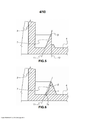
[0045] Essas e outras vantagens serão discutidas em maiores detalhes com referência aos desenhos anexos, que são fornecidos somente por meio de exemplo e não devem ser interpretados como limitando o escopo da invenção. Nos desenhos: As Figura 1, Figura 2 e Figura 2A são concretizações exemplares do estado da técnica; A Figura 3 é uma corte transversal esquemática de uma realização exemplar do sistema; A Figura 4 é uma vista em seção ampliada de um elemento de vedação exemplar de acordo com a invenção; A Figura 5 e 6 são vistas em seção de outras concretizações exemplares do elemento de vedação; As Figuras 7A e 7B mostram duas posições possíveis do receptáculo do dispositivo de infusão com relação à saliência de vedação da invenção; As Figura 8 e 9 são duas seções cruzadas mostrando outra realização da invenção e a interação da porção de prensa do receptáculo e saliência de vedação; As Figura 10 e 11 mostra outra possível realização da invenção; e As Figuras 12, 12A e 12B são vistas em seção ampliadas de outras possíveis concretizações da saliência de vedação da cápsula de acordo com a invenção.[0045] These and other advantages will be discussed in greater detail with reference to the accompanying drawings, which are provided by way of example only and should not be construed as limiting the scope of the invention. In the drawings: Figures 1, Figure 2 and Figure 2A are exemplary embodiments of the state of the art; Figure 3 is a schematic cross-section of an exemplary embodiment of the system; Figure 4 is an enlarged sectional view of an exemplary sealing element according to the invention; Figures 5 and 6 are seen in section of other exemplary embodiments of the sealing element; Figures 7A and 7B show two possible positions of the infusion device receptacle with respect to the sealing protrusion of the invention; Figures 8 and 9 are two cross sections showing another embodiment of the invention and the interaction of the press portion of the receptacle and sealing protrusion; Figures 10 and 11 show another possible embodiment of the invention; and Figures 12, 12A and 12B are enlarged section views of other possible embodiments of the capsule sealing protrusion according to the invention.
[0046] Com referência inicial às figuras 1 - 2A, essas figuras referem-se ao estado da técnica e exemplificam como o sistema está funcionando somente se a posição e as dimensões dos componentes do sistema estiverem dentro das faixas precisas. A Figura 2A é exemplar da dificuldade em obter uma boa vedação da cápsula no flange em alguns dispositivos de infusão comercialmente disponíveis usando aquele tipo de receptáculo. Nesta realização, o receptáculo é mencionado para ter uma porção de prensa formada por duas coroas circulares (borda interna e borda externa) conectadas por um recesso anular, cada borda é fornecida com irregularidades, recuos e/ou lacunas.[0046] With initial reference to figures 1 - 2A, these figures refer to the state of the art and exemplify how the system is working only if the position and dimensions of the components of the system are within the precise ranges. Figure 2A is an example of the difficulty in obtaining a good seal of the capsule on the flange in some commercially available infusion devices using that type of receptacle. In this embodiment, the receptacle is mentioned to have a press portion formed by two circular crowns (inner edge and outer edge) connected by an annular recess, each edge is provided with irregularities, indentations and / or gaps.
[0047] A Figura 3 mostra uma combinação da cápsula e parte do dispositivo de infusão de acordo com a invenção. Mais em detalhes, o sistema para preparar uma bebida compreende uma cápsula 1 e um dispositivo de infusão. A cápsula está compreendendo um corpo oco 6 incluindo uma parede lateral 2, uma parede de entrada 3, um rebordo semelhante a flange 4 e uma saliência 5 estendendo-se para fora do referido rebordo de flange. De modo geral, a saliência 5 estende-se ao longo de uma circunferência que tem um centro correspondente ao eixo da cápsula (ou simétrico de modo giratório); a parte inferior ou de fundo da parede lateral 2 é preferivelmente curvada para auxiliar a centralizar a cápsula no receptáculo.[0047] Figure 3 shows a combination of the capsule and part of the infusion device according to the invention. In more detail, the system for preparing a drink comprises a
[0048] O dispositivo de infusão 20 compreende um receptáculo 21 móvel com relação a uma placa de recebimento 22 do dispositivo de infusão a partir de uma posição aberta para uma posição fechada para alojar pelo menos parte do corpo oco da cápsula no receptáculo de fechamento 21 e para fornecer uma câmara fechada em torno da cápsula quando a água aquecida e pressurizada é alimentada ao interior da referida cápsula durante a etapa de infusão. A placa 22 é fornecida com simplesmente um ou poucos ou ainda uma pluralidade de orifícios 14 para deixar a bebida fluir para seu recipiente final. O receptáculo 21 é fornecido com uma borda de prensa 10 tendo uma porção externa 10a, i.e., a porção externa voltada para longe a partir da parede lateral 2 da cápsula. O receptáculo mostrado no lado esquerdo da figura 3 é do tipo tendo uma coroa dupla, de modo semelhante ao mostrado na figura 2A, e tem duas coroas circulares (borda interna 10 e borda externa 19) conectadas por um recesso anular 18, cada borda é fornecida com irregularidades, recuos e/ou lacunas. A borda externa 19 é mais curta do que a borda interna 10, De acordo com a invenção, somente a borda interna 10 é usada para conduzir a vedação exigida, possivelmente com o recesso anular 18, e a borda externa 19 não está comprimindo o flange ou parte do mesmo. O receptáculo mostrado no lado direito da figura 3 é do tipo de coroa única, com uma única borda de prensa 10 fornecida com uma borda externa 10a, que é a parte da borda que contatará a saliência de vedação 5.[0048] The
[0049] Nas figuras anexadas restantes, o receptáculo 21 sempre é esquematicamente mostrado tendo um formato cruzado substancialmente retangular e somente a borda de prensa 10 é mostrada, essa sendo a porção do receptáculo onde a ação de vedação é conduzida. Não obstante isso, o receptáculo 21 do dispositivo de infusão poderia ser fornecido com diferentes formatos, por exemplo, com borda arredondada ou borda descontínua, e também, nesses casos, uma porção externa 10a da borda de prensa 10 pode ser identificada, por exemplo, em correspondência da porção conectando a superfície externa lateral com a superfície de prensa de fundo (i.e., borda 10) do receptáculo e com a área de borda 10 imediatamente adjacente à referida porção de conexão.[0049] In the remaining attached figures,
[0050] Em uma realização exemplar da invenção, o diâmetro externo máximo da parede lateral 2 da cápsula, i.e., o diâmetro medido no cruzamento com o flange 4, é igual ao diâmetro interno do receptáculo 21, e o diâmetro externo do receptáculo 21 é igual ao diâmetro do círculo definido pela saliência de vedação 5 (conforme previamente mencionado, a saliência está na forma de uma circunferência concêntrica com a parede lateral 2 da cápsula).[0050] In an exemplary embodiment of the invention, the maximum outer diameter of the
[0051] A cápsula também compreende uma tampa 13 que forma a parede de saída da cápsula e que é parcialmente anexada ao rebordo de flange 4 do corpo de cápsula. A tampa 13 mostrada na figura 3 é uma tampa de plástico fornecida com porções de projeção que atuam como saídas de auto perfuração assim que são comprimidas contra a placa 22, opcionalmente com o auxílio da pressão dentro da cápsula. A parede de flange e tampa são soldadas juntas em um local que está preferivelmente entre a borda do rebordo de flange e a saliência de vedação 5. A tampa não é mostrada nas figuras 4-11, para fins de uma maior simplicidade dos desenhos.[0051] The capsule also comprises a
[0052] Conforme mencionado, a tampa pode também ser feita com diferente tecnologia do que aquela acima descrita. Por exemplo, um elemento de folha metálica, em plásticos laminados ou a partir de outros materiais, tais como, biomaterial, plástico derivado a partir de energia renovável ou materiais de liga incluindo uma base metálica; um elemento típico de folha metálica está compreendendo a(s) camada(s) de alumínio acoplada(s) com a camada de plástico para fornecer propriedades mecânicas e de barreira de gás, soldadas a uma porção correspondente do flange. Outras soluções disponíveis para o técnico no assunto compreendem folhas de plástico pré- perfuradas, tampas de plástico com orifícios pré-cortados, ou papel de filtro.[0052] As mentioned, the cover can also be made with different technology than the one described above. For example, a sheet metal element, in laminated plastics or from other materials, such as, biomaterial, plastic derived from renewable energy or alloy materials including a metallic base; a typical sheet metal element is comprising the aluminum layer (s) coupled with the plastic layer to provide mechanical and gas barrier properties, welded to a corresponding portion of the flange. Other solutions available to the person skilled in the art include pre-punched plastic sheets, plastic lids with pre-cut holes, or filter paper.
[0053] Na realização exemplar da figura 3, a cápsula 2 é uma cápsula vedada que recebe a água exigida a partir do canal 15 da base do receptáculo 21. As lâminas 16 perfuram a parede de entrada 3 para fornecer as passagens para a água entrando na cápsula. Conforme previamente mencionado, outros designs dos receptáculos e sistemas de alimentação de água também podem ser usados, p.ex., para uma cápsula que não é vedada e onde a parede de entrada 3 tem uma pluralidade de passagens ou entradas de água podem ser criadas na parede de entrada de água da cápsula ao perfurar uma folha metálica usando estacas construídas na referida parede de entrada de água (tal como, em WO2006/030461 pelo Depositante), nenhuma lâmina 16 é exigida.[0053] In the exemplary embodiment of figure 3,
[0054] O flange 4 é dividido pela saliência de vedação 5 em duas porções que são preferivelmente coplanares; entretanto, as duas porções poderiam estar em diferentes planos. A saliência, ou elemento de vedação, 5 tem qualquer formato adequado de corte transversal, tal como, o formato exemplar de um triângulo mostrado nas figuras 4, 7, ou tal como, os formatos da figura 5 e 6, ou tal como, o formato mostrado nas figuras 12 e 12A. Os triângulos truncados, i.e., trapézios, ou outros formatos da corte transversal da saliência, também podem ser usados, contanto que a parte superior seja deformável de modo plástico e o lado em que a borda externa 10a insistirá em uma condição fechada, tem a inclinação exigida. Independentemente, no formato da corte transversal da saliência 5, o elemento de vedação 5 tem pelo menos um lado 7 que é inclinado por um ângulo interno α com relação ao plano do rebordo de flange 4, o referido ângulo α, a posição da saliência no flange e a altura H da saliência (medida a partir do plano P, ver a figura 4), estão dispostas para ter a saliência 5 contatando a porção externa 10a da borda 10 do receptáculo 21 pelo menos em um local selecionado a partir da parte superior 8 e o lado 7 da saliência, ou ambos.[0054] The
[0055] O ângulo de inclinação α do referido pelo menos um lado 7 da saliência de vedação 5 é medido, conforme mostrado nas figuras, entre o lado inclinado e o plano P passando através da superfície superior do rebordo semelhante a flange fora da saliência de vedação 5.[0055] The angle of inclination α of said at least one
[0056] Conforme mostrado na figura, o ângulo de inclinação α é preferivelmente medido a partir do plano P da porção do rebordo semelhante a flange 4 que está adjacente à parede lateral 2 da cápsula. O ângulo α está dentro de faixa de 80 até 40 graus, preferivelmente na faixa de 80 até 60 graus, mais preferivelmente na faixa de 75 até 60 graus, e mais preferivelmente na faixa de 70 até 65 graus, e é medido com referência ao plano em que o lado 7 está; se o referido lado for irregular ou côncavo/convexo, ou tiver um formato que não é plano, com a finalidade de medir o ângulo α, um plano virtual é definido para o lado 7 ao traçar uma linha 11 entre a parte superior 8 e ponto 7a, onde o flange 4 encontra o lado 7, conforme mostrado na figura 6. Na realização preferida, o lado inclinado 7 é o lado interno, i.e., o lado que está voltado para a parede lateral 2 da cápsula 1. Conforme previamente mencionado, o lado 7, i.e., o lado que deverá, ou poderia, contatar a porção externa da borda 10 do receptáculo 21, pode ser irregular, conforme na figura 5, ou côncavo, conforme na figura 6, ou ter outros formatos, p.ex., em degrau. Em todos os casos, o lado 7 é inclinado com relação ao plano P do flange e define um ângulo interno α. Por "ângulo interno" significa o ângulo que é interno à projeção 5, i.e., o ângulo voltado para longe a partir da parede lateral 2 da cápsula.[0056] As shown in the figure, the angle of inclination α is preferably measured from the plane P of the flange-like portion of the
[0057] O formato das seções cruzadas da saliência 5 de modo geral está na forma de um triângulo ou de um triângulo truncado e o triângulo pode ser selecionado a partir de triângulos retângulos e escalenos, ou a partir de triângulos isósceles; quando a saliência está na forma de um triângulo isóscele, o ângulo α está preferivelmente na faixa de 80 até 70 graus. Preferivelmente, o ângulo β dos vértices da parte superior dos referidos triângulos está na faixa de 10 até 44 graus, preferivelmente 15 até 35 graus; os mesmos valores se aplicam aos outros formatos, para esses formatos, o ângulo β é definido ao identificar um plano para os lados da saliência de um modo semelhante ao que é mostrado na figura 5 e 6 com os planos virtuais 11 e 12. Desse modo, pode ser garantido que a parte superior da saliência é suficientemente fina para ser pelo menos parcialmente deformada de modo plástico quando comprimida pela borda do receptáculo de modo a compensar diferentes posições de extremidade dos receptáculos de diferentes dispositivos de infusão, ainda permitindo o meio ideal de vedação.[0057] The shape of the cross sections of the
[0058] De acordo com diferentes possíveis concretizações, o formato da saliência de vedação 5 entre o lado inclinado 7 e a borda periférica 4a do rebordo semelhante a flange 4 pode ser diferente.[0058] According to different possible embodiments, the shape of the sealing
[0059] Conforme acima mencionado, a saliência de vedação 5 forma pelo menos uma porção da espessura aumentada do rebordo semelhante a flange 4, e de acordo com uma possível realização, a porção da espessura aumentada da saliência de vedação está estendendo-se a partir do referido pelo menos um lado 7 em direção à borda periférica 4a do rebordo semelhante a flange 4.[0059] As mentioned above, the sealing
[0060] Deve ser observado que a saliência de vedação 5 formando uma porção de espessura aumentada do rebordo semelhante a flange 4 da cápsula pode estender-se por todo o espaço entre pelo menos um lado inclinado 7 e a borda periférica 4a do flange, conforme revelado na realização mostrada na vista em seção da figura 12A.[0060] It should be noted that the sealing
[0061] Mais detalhadamente, na realização mostrada na figura 12A, a saliência de vedação 5 compreende um lado inclinado 7, isto é, um lado interno, voltado à parede lateral 2 da cápsula, tendo o ângulo de inclinação α exigido; a saliência 5 forma uma porção de espessura aumentada do rebordo semelhante a flange 4 estendendo-se completamente entre o referido lado 7 e a borda 4a do rebordo semelhante a flange 4. Em outras palavras, na realização mostrada na figura 12A, a saliência de vedação 5 forma uma espessura aumentada do rebordo semelhante a flange 4 com relação à espessura do rebordo semelhante a flange fora da saliência de vedação, e particularmente com relação à porção do rebordo semelhante a flange adjacente à parede lateral 2 da cápsula.[0061] In more detail, in the embodiment shown in figure 12A, the sealing
[0062] Conforme mostrado na figura 12A, a porção da espessura aumentada do rebordo semelhante a flange compreende uma superfície plana 12 estendendo-se a partir da parte superior 8 da saliência de vedação 5 à borda do referido rebordo semelhante a flange 4. Na realização mostrada, a superfície plana é paralela à superfície inferior do rebordo semelhante a flange 4, desse modo, uma porção tendo uma espessura aumentada constante é formada entre o lado 7 e a borda 4a do rebordo semelhante a flange 4.[0062] As shown in figure 12A, the increased thickness portion of the flange-like lip comprises a
[0063] Entretanto, de acordo com diferentes possíveis concretizações não mostradas nas figuras, a superfície plana pode não se estender a partir da parte superior da saliência de vedação, porém em uma distância a partir da parte superior. Preferivelmente, a saliência de vedação 5 forma entre o lado 7 e a borda 4a do flange 4 uma espessura aumentada constante, i.e., a saliência de vedação é fornecida com um lado 7 e estende-se em direção à borda 4a do flange 4 com uma superfície substancialmente plana superior 12.[0063] However, according to different possible embodiments not shown in the figures, the flat surface may not extend from the top of the sealing overhang, but at a distance from the top. Preferably, the sealing
[0064] Entretanto, de acordo com diferentes possíveis concretizações, uma variação da espessura da saliência de vedação entre o lado 7 e a borda 4a do flange 4 pode ser fornecida.[0064] However, according to different possible embodiments, a variation in the thickness of the sealing protrusion between
[0065] Adicionalmente, deve ser observado que mesmo se somente uma vista em seção, obtida ao longo de um plano radial passando através de um eixo central da cápsula é mostrada na figura 12A, a saliência de vedação 5 estende-se continuamente por toda a circunferência do flange 4, em outras palavras, toda a seção obtida ao longo da circunferência do flange 4 é preferivelmente igual entre si. De acordo com outra possível realização da cápsula de acordo com a invenção, ver, por exemplo, a figura 12, a saliência de vedação 5 formando uma espessura aumentada do rebordo semelhante a flange 4 está estendendo-se somente para uma parte do espaço entre o lado inclinado 7 e a borda periférica 4a do rebordo semelhante a flange 4.[0065] Additionally, it should be noted that even if only a sectional view, obtained along a radial plane passing through a central axis of the capsule is shown in figure 12A, the sealing
[0066] Na realização mostrada na figura 12, a saliência de vedação 5 compreende pelo menos um lado 7 que é inclinado por um ângulo interno α com relação ao plano do rebordo de flange 4. O lado inclinado 7 é o lado interno da saliência de vedação 5 voltado à parede lateral 2 da cápsula.[0066] In the embodiment shown in figure 12, the sealing
[0067] Conforme acima mencionado, o ângulo α está dentro de faixa de 80 até 40 graus, preferivelmente na faixa de 80 até 60 graus, mais preferivelmente na faixa de 75 até 60 graus, e na maioria preferivelmente na faixa de 70 até 65 graus, e é medido entre o plano em que o lado 7 está e o plano P passando através da superfície do rebordo semelhante a flange 4 a partir da qual a saliência de vedação 5 está se projetando, i.e., a superfície do rebordo semelhante a flange 4 a partir da qual a saliência de vedação 5 define uma porção tendo uma espessura aumentada.[0067] As mentioned above, the angle α is within the range of 80 to 40 degrees, preferably in the range of 80 to 60 degrees, more preferably in the range of 75 to 60 degrees, and most preferably in the range of 70 to 65 degrees , and is measured between the plane on which
[0068] Conforme mostrado na figura 12, o ângulo de inclinação α é medido a partir da superfície superior da porção do rebordo semelhante a flange 4 adjacente à parede lateral 2.[0068] As shown in figure 12, the angle of inclination α is measured from the upper surface of the flange-
[0069] Na realização mostrada, o ângulo α é substancialmente de 67 graus.[0069] In the shown embodiment, the angle α is substantially 67 degrees.
[0070] Na realização mostrada na figura 12, a saliência de vedação 5 forma uma espessura aumentada do rebordo semelhante a flange com relação à porção do referido flange adjacente à parede lateral 2 da cápsula.[0070] In the embodiment shown in figure 12, the sealing
[0071] Da mesma forma nesta realização, o lado 7 pode ser irregular ou côncavo/convexo, ou de modo geral pode ser fornecido com um formato que não é plano. Nesses casos, com a finalidade de medir o ângulo α, um plano virtual é definido para o lado 7 ao traçar uma linha 11 entre a parte superior 8 e o ponto 7a, onde o flange 4 encontra-se com o lado 7, conforme mostrado na figura 12.[0071] Likewise in this embodiment,
[0072] Deve ser observado que mesmo se, na realização mostrada na figura 12, o lado 7 tiver um ponto redondo de incidência com a superfície superior (plano P) do rebordo semelhante a flange 4, é possível identificar um ponto imaginário onde a projeção do lado 7 e a projeção da superfície (plano P) do rebordo semelhante a flange são incidentes. Adicionalmente, a porção de parte superior 8 do lado 7 pode ser identificada na realização mostrada na figura 12 devido à alteração da inclinação em direção à borda periférica 4a do rebordo de flange 4.[0072] It should be noted that even if, in the embodiment shown in figure 12,
[0073] Na realização da figura 12B, a parte da saliência adjacente ao lado 7 tem um vértice ou parte superior 8 que está no formato de um triângulo, a parte externa restante do rebordo sendo idêntica àquela da realização da figura 12.[0073] In the realization of figure 12B, the part of the projection adjacent to
[0074] Conforme será posteriormente revelado, a distância L entre a parte superior 8 da saliência 5 e parede lateral 2 da cápsula é compreendida na faixa de 0,6 mm até 1,0 mm, e na realização mostrada na figura 12 é preferivelmente 0,7 mm. Nesta realização, a distância L1 é preferivelmente 0,5 até 0,6 mm.[0074] As will be revealed later, the distance L between the
[0075] Conforme mostrado na figura 12, a porção de espessura aumentada do rebordo semelhante a flange 4 formada pela saliência de vedação 5 compreende uma superfície plana estendendo-se a partir do referido lado inclinado 7 à borda 4a do rebordo semelhante a flange. Preferivelmente, a superfície plana da porção mais espessa está estendendo-se a partir da parte superior 8 do lado inclinado 7 da saliência de vedação 5.[0075] As shown in figure 12, the increased thickness portion of the flange-
[0076] Na realização mostrada, o ângulo β dos vértices da parte superior da saliência 5, i.e., o ângulo medido entre o lado inclinado 7 e a superfície substancialmente plana estendendo-se a partir do lado inclinado 7, é superior a 90 graus, preferivelmente superior a 100 graus. Na realização mostrada na figura 12, o ângulo β é substancialmente de 110 graus.[0076] In the shown embodiment, the angle β of the vertices of the upper part of the
[0077] Conforme já mencionado, de acordo com uma possível realização, conforme mostrado nas figuras 12 e 12B, a saliência de vedação 5 forma uma porção mais espessa do rebordo semelhante a flange estendendo-se somente por uma parte do espaço entre o lado inclinado 7 da saliência de vedação 5 e a borda periférica do rebordo semelhante a flange 4.[0077] As already mentioned, according to a possible embodiment, as shown in figures 12 and 12B, the sealing
[0078] Em outras palavras, conforme mostrado na figura 12, a saliência de vedação 5 está estendendo-se em direção à borda periférica 4a do rebordo semelhante a flange 4, porém não para a extensão completa do rebordo semelhante a flange 4.[0078] In other words, as shown in figure 12, the sealing
[0079] Mais detalhadamente, na realização mostrada na figura 12 e 12B, o rebordo semelhante a flange 4 termina com uma borda substancialmente em formato de L (em uma vista em seção radial). A porção de extremidade da borda em formato de L é direcionada para longe da parede de entrada 3 da cápsula. Esta configuração permite formar uma cavidade 17 em correspondência da superfície inferior do rebordo semelhante a flange 4.[0079] In more detail, in the embodiment shown in figures 12 and 12B, the flange-
[0080] De fato, o rebordo semelhante a flange 4 é modelada para compreender uma cavidade 17 que está localizada abaixo do flange 4, i.e., em correspondência da superfície do flange 4 que é voltada para longe a partir da parede de entrada 3 da cápsula. A cavidade 17 está disposta, na realização mostrada da figura 12, em correspondência da borda 4a do flange 4, e particularmente adjacente à saliência de vedação 5. A cavidade está preferivelmente estendendo-se por toda a extensão circunferencial do rebordo semelhante a flange 4. pode ser interrompido.[0080] In fact, the flange-
[0081] Entretanto, de acordo com diferentes possíveis concretizações, conforme mostrado na figura 8 que será revelado posteriormente em maiores detalhes, a cavidade 17 também pode estar disposta em correspondência da saliência de vedação 5.[0081] However, according to different possible embodiments, as shown in figure 8 which will be revealed in more detail later, the
[0082] O formato substancialmente em L da borda 4a do rebordo semelhante a flange 4 torna a borda do rebordo semelhante a flange 4 mais flexível, desse modo, pode ser adaptado para diferentes dispositivos de infusão, assim reduzindo dificuldades para remover a cápsula do dispositivo de infusão no final do processo de preparo de bebida.[0082] The substantially L-shape of the
[0083] Na realização exemplar conforme mostrada nas figuras 12 e 12B, a porção em formato de L do flange é mais curta do que a altura total do flange 4, i.e., a extremidade inferior da porção em L do flange para em uma distância a partir do plano P' do lado inferior do flange; o lado inferior do flange significa o lado do flange voltado para longe a partir da parede de entrada para a água. Uma etapa 13 é preferivelmente fornecida onde a cavidade 17 atinge o plano P' do lado inferior do flange 4.[0083] In the exemplary embodiment as shown in figures 12 and 12B, the L-shaped portion of the flange is shorter than the total height of the
[0084] Adicionalmente, conforme válido para todas as figuras e conforme já mencionado acima com relação à figura 12A, a saliência de vedação 5 é circular, i.e., ela se estende continuamente por toda a circunferência do flange 4, em outras palavras, todas as seções obtidas ao longo da circunferência do flange 4 são preferivelmente iguais entre si.[0084] Additionally, as valid for all figures and as already mentioned above with respect to figure 12A, the sealing
[0085] Como uma regra geral, a altura H (figura 4) da saliência 5, que é medida a partir do plano P do lado superior do flange 4, i.e., o lado voltado à parede de entrada 3, está dentro de faixa de 0,3 até 1,3 mm, preferivelmente 0,6 até 1,0, na maioria preferivelmente é de 0,8 ou 0,9 mm. A distância L entre a parte superior 8 da saliência e parede 2 da cápsula é preferivelmente igual ou superior à largura W da borda 10 do receptáculo 21. No caso em que a distância L seja superior à largura W da borda 10 do receptáculo, a distância L é preferivelmente até 1,5 vez superior à largura W da borda 10 (ver, p.ex., a figura 4), i.e., 1,0W ^ L ^ 1,5W. Em uma realização exemplar, L está na faixa de 0,6 mm até 1,0 mm, preferivelmente 0,7 mm; L1 é 0,4 mm até 0,7 mm, preferivelmente 0,5 mm até 0,7 mm. Adicionalmente, os valores preferidos da distância L1 são compreendidos na faixa de 0,63mm até 0,67mm, e na faixa de 0,5 mm até 0,55 mm. De acordo com uma possível realização, L1 é 0,65 mm e H é 0,8. Em qualquer caso, L1 sempre é mais curto do que L.[0085] As a general rule, the height H (figure 4) of the
[0086] Na presente descrição, a largura W da borda é referida à parte do receptáculo que está efetivamente envolvida na ação de vedação.[0086] In the present description, the width W of the edge is referred to the part of the receptacle that is effectively involved in the sealing action.
[0087] De acordo com uma possível realização, a distância L1 (ver a Figura 4) entre a parede lateral 2 da cápsula e a extremidade do fundo 7a do lado inclinado 7 da referida saliência 5 é mais curta do que a largura W da borda 10 do referido receptáculo, i.e., L1<W. 7a é o ponto definido pelo cruzamento do lado inclinado 7 da saliência 5 e superfície superior do rebordo semelhante a flange 4.[0087] According to a possible embodiment, the distance L1 (see Figure 4) between the
[0088] Neste caso, a porção externa 10a da borda de prensa 10 do receptáculo 21 está geralmente localizada pelo menos parcialmente entre a parte superior 8 da saliência 5 e a parede lateral 2 da cápsula 1, porém também poderia estar totalmente localizada entre a parte superior 8 e parede de cápsula 2. Duas possíveis posições da borda 10 são mostradas na figura 7A e 7B para mostrar como a saliência da invenção pode compensar as diferenças nos caminhos de compressão (e ainda diferenças na largura W); na figura 7A, o caminho de compressão do receptáculo 21 é mais curto do que na figura 7B e a distância da borda de compressão 10 a partir do flange 4 é superior em 7A do que em 7B. Entretanto, graças ao design da saliência de vedação, uma vedação é obtida em ambos os casos: na figura 7A, a porção externa 10a da borda 10 do receptáculo 21 está insistindo no lado inclinado 7 da saliência 5. Na figura 7B, onde a distância de borda 10 - flange 4 é menor, a borda 10 está insistindo no lado 7 (lado interno) da saliência 5 com sua porção externa 10a e pelo menos uma porção da borda de prensa 10, aqui, sua porção interna 10b, está insistindo também na parede lateral 2 da cápsula. O lado interno 7 da saliência 5 será parcialmente deformado para acomodar o caminho de compressão extra, adicionalmente, algum grau de movimento lateral da saliência 5, devido ao fato de que é feito de material termoplástico, auxiliará a acomodar o receptáculo 21 na posição da figura 7B.[0088] In this case, the
[0089] Durante a etapa de infusão, isso resultará em um tipo de câmara fechada abaixo da borda do receptáculo 10. Além do mais, de acordo com outra possível realização, não mostrada nas figuras, na condição fechada ou na etapa de infusão, a borda 10 do receptáculo 21 está em contato com a saliência 5, e particularmente pelo menos um ponto de seu lado inclinado 7, a parede lateral 2 da cápsula e pelo menos uma porção do rebordo semelhante a flange 4 da cápsula compreendida entre a parede lateral 2 e o lado inclinado 7 da saliência.[0089] During the infusion step, this will result in a type of closed chamber below the edge of the
[0090] A Figura 8 mostra outra realização da invenção. Nesta realização, a saliência 5 é fornecida com uma cavidade 17 que está localizada abaixo da saliência 5 e/ou abaixo do flange 4. Na figura 8, parte da cavidade 17 é obtida na parte esquerda do flange 4, porém também pode se estender no lado esquerdo, ou lado interno, do flange com relação à saliência 5. A função dessa cavidade é para fornecer flexibilidade adicional da saliência de vedação e para aumentar sua capacidade de deformação para adaptar-se a diferentes tipos de receptáculos 21.[0090] Figure 8 shows another embodiment of the invention. In this embodiment, the
[0091] A Figura 9 esquematicamente mostra uma condição comprimida possível da saliência de vedação da figura 8 que inclinou de acordo com a direção da seta F na figura 8. No caso de uma compressão na parte superior 8, a saliência também encolherá verticalmente. Os detalhes adicionais nesta realização podem ser encontrados no pedido copendente EP 12005215.4 "CÁPSULA COM ELEMENTO DE VEDAÇÃO MELHORADO" depositado pelo mesmo depositante no mesmo dia que o presente pedido. O referido documento é aqui incorporado por referência.[0091] Figure 9 schematically shows a possible compressed condition of the sealing overhang of figure 8 that tilted according to the direction of the arrow F in figure 8. In the case of a compression at the top 8, the overhang will also shrink vertically. Additional details on this realization can be found in copying order EP 12005215.4 "CAPSULE WITH IMPROVED SEALING ELEMENT" deposited by the same depositor on the same day as the present order. Said document is incorporated herein by reference.
[0092] As Figs. 10 e 11 mostram outra realização da invenção, onde uma pluralidade de sulcos ou elementos de projeção 24 está estendendo-se radialmente a partir da parede lateral da cápsula 2 para a saliência de vedação 5. A função dos elementos 24 é para adaptar as irregularidades ou recuos da borda de prensa 10 e melhorar a vedação: para essa finalidade, o formato dos elementos 24 é, em uma realização, substancialmente correspondente ao da borda de prensa 10, p.ex., como elementos 24 (figura 10) que têm um formato redondo/elíptico. Na figura 10 também são mostrados elementos alternativos estendendo-se de modo radial 23: esses elementos têm a mesma função dos elementos 24, porém estão na forma de paredes finas estendendo-se radialmente a partir da parede lateral 2 da cápsula ou a partir da saliência 5. Os elementos 23 e 24 não necessariamente estendem-se ao longo de todo o comprimento a partir da saliência à cápsula. Essas paredes são modeladas, dimensionadas e posicionadas de modo a deformar sob a borda de prensa 10 e adaptar-se aos seus recuos (se presente).[0092] Figs. 10 and 11 show another embodiment of the invention, where a plurality of grooves or
[0093] Resumindo, o meio de vedação, ou saliência, 5 da invenção combina uma porção de parte superior que é deformável de modo plástico com um lado 7 da saliência 5 que está inclinado com relação ao plano de flange P por um ângulo interno α dentro de faixa de 80 até 40 graus, preferivelmente dentro de faixa de 80 até 60 graus, mais preferivelmente 75 até 60 graus, e na maioria preferivelmente 70 até 65 graus.[0093] In summary, the sealing means, or protrusion, 5 of the invention combines a portion of the upper part that is plastic deformable with a
[0094] A porção de parte superior pode ser definida com um ângulo de 15 até 45 graus, se a saliência de vedação for substancialmente modelada como um triângulo ou com um ângulo superior maior que 60 graus, preferivelmente superior a 90 graus, e na maioria preferivelmente superior a 100 graus, se a saliência de vedação compreender uma porção da espessura aumentada estendendo-se a partir do lado inclinado 7, conforme, por exemplo, mostrado nas figuras 12 e 12A. A distância L da parte superior 8 da saliência 5 a partir da parede lateral 2 da cápsula é igual ou superior à largura W da borda 10 do(s) receptáculo(s) 21 e é tal de modo a ter o receptáculo 21 do dispositivo de infusão para insistir na parte superior da saliência ou, preferivelmente, no lado da saliência. Em uma realização preferida, a borda do receptáculo insiste em ambos o lado da saliência e a parede lateral da cápsula.[0094] The upper portion can be defined with an angle of 15 to 45 degrees, if the sealing projection is substantially modeled as a triangle or with an upper angle greater than 60 degrees, preferably greater than 90 degrees, and in most preferably greater than 100 degrees, if the sealing protrusion comprises a portion of the increased thickness extending from the
[0095] A combinação revelada é adequada para compensar diferentes caminhos de compressão do receptáculo e, portanto, para fornecer um elemento de vedação adaptável que pode ser usado em diferentes modelos dos dispositivos de infusão que incluem um receptáculo 21 e uma placa de recebimento 22. Adicionalmente, a combinação acima reduz a força geral exigida para vedação do receptáculo no flange da cápsula.[0095] The disclosed combination is suitable to compensate for different compression paths of the receptacle and, therefore, to provide an adaptable sealing element that can be used in different models of infusion devices that include a
[0096] Os elementos adicionais estendendo-se de modo radial 23, 24 fornecem uma vedação melhorada do receptáculo 21 no flange 4 da cápsula, per se ou em combinação com a saliência de vedação.[0096] The additional elements extending radially 23, 24 provide an improved seal of the
Claims (27)
Applications Claiming Priority (3)
| Application Number | Priority Date | Filing Date | Title |
|---|---|---|---|
| EP12005216.2 | 2012-07-16 | ||
| EP12005216 | 2012-07-16 | ||
| PCT/EP2013/063873 WO2014012783A2 (en) | 2012-07-16 | 2013-07-01 | Capsule and brewing system with adaptable sealing element |
Publications (2)
| Publication Number | Publication Date |
|---|---|
| BR112015001039A2 BR112015001039A2 (en) | 2017-06-27 |
| BR112015001039B1 true BR112015001039B1 (en) | 2021-01-26 |
Family
ID=48703583
Family Applications (1)
| Application Number | Title | Priority Date | Filing Date |
|---|---|---|---|
| BR112015001039-3A BR112015001039B1 (en) | 2012-07-16 | 2013-07-01 | system for preparing a drink |
Country Status (14)
| Country | Link |
|---|---|
| US (1) | US20150208852A1 (en) |
| EP (2) | EP3199473B1 (en) |
| JP (1) | JP6364407B2 (en) |
| KR (2) | KR102271739B1 (en) |
| CN (1) | CN105164025B (en) |
| AU (2) | AU2013292241B2 (en) |
| BR (1) | BR112015001039B1 (en) |
| CA (1) | CA2878896C (en) |
| DK (1) | DK2872421T3 (en) |
| ES (2) | ES2837416T3 (en) |
| HK (1) | HK1214803A1 (en) |
| PL (1) | PL2872421T3 (en) |
| RU (1) | RU2633241C2 (en) |
| WO (1) | WO2014012783A2 (en) |
Families Citing this family (51)
| Publication number | Priority date | Publication date | Assignee | Title |
|---|---|---|---|---|
| US10722066B2 (en) * | 2010-12-04 | 2020-07-28 | Adrian Rivera | Windowed single serving brewing material holder |
| US11832755B2 (en) * | 2007-07-13 | 2023-12-05 | Adrian Rivera | Brewing material container for a beverage brewer |
| HUE048822T2 (en) * | 2010-07-22 | 2020-08-28 | K Fee System Gmbh | Portion capsule with barcode |
| ES2837416T3 (en) | 2012-07-16 | 2021-06-30 | Tuttoespresso Srl | Capsule and system with sealing element |
| EP2981480B1 (en) | 2013-04-03 | 2019-05-01 | Koninklijke Douwe Egberts B.V. | Pad comprising a soluble beverage preparation product for use in a coffee machine |
| AU2014250125A1 (en) * | 2013-04-03 | 2015-11-05 | Koninklijke Douwe Egberts B.V. | Pad with a relatively large outlet opening comprising a soluble beverage preparation product for use in a coffee machine |
| MX2015014000A (en) | 2013-04-03 | 2016-02-10 | Koninkl Douwe Egberts Bv | Coffee pad with a relatively large outlet opening for use in a coffee machine. |
| RU2015146994A (en) | 2013-04-03 | 2017-05-11 | Конинклейке Дауве Егбертс Б.В. | COFFEE LOAD FOR USE IN A COFFEE MACHINE |
| EP2984004B1 (en) * | 2013-04-10 | 2017-11-29 | Tuttoespresso S.r.l. | Capsule and system for preparing beverages |
| WO2014184652A1 (en) | 2013-05-17 | 2014-11-20 | Kraft Foods R&D, Inc. | A beverage preparation system, a capsule and a method for forming a beverage |
| GB201308927D0 (en) | 2013-05-17 | 2013-07-03 | Kraft Foods R & D Inc | A beverage preparation system, a capsule and a method for forming a beverage |
| ITMI20130975A1 (en) * | 2013-06-13 | 2014-12-14 | Goglio Spa | CARTRIDGE FOR SOLUBLE PRODUCTS WITH SEALING ELEMENT |
| ITVR20130243A1 (en) | 2013-11-08 | 2015-05-09 | Caffita System Spa | CAPSULE AND BEVERAGE PRODUCTION SYSTEM |
| WO2015101394A1 (en) * | 2013-12-30 | 2015-07-09 | Landmax Ltd | Capsule for a beverage preparation with deformable sealing element |
| GB2548646A (en) | 2014-01-03 | 2017-09-27 | Douwe Egberts Bv | Exchangeable supply pack for a beverage dispensing machine, doser, pump assembly and method of manufacturing |
| BR112016024395B1 (en) | 2014-04-22 | 2021-04-13 | Macchiavelli S.R.L | CAPSULE FOR INFUSION PRODUCTS, IN PARTICULAR COFFEE |
| CN107074436B (en) * | 2014-09-17 | 2020-04-28 | 戴维·鲁宾斯坦 | Sealed container for beverage preparation |
| GB201420262D0 (en) | 2014-11-14 | 2014-12-31 | Kraft Foods R & D Inc | A method of forming a cup-shaped body for a beverage capsule |
| CA2985971C (en) | 2015-05-15 | 2024-01-09 | Koninklijke Douwe Egberts B.V. | A capsule, a system for preparing a potable beverage from such a capsule and use of such a capsule in a beverage preparation device |
| CN107835774B (en) | 2015-05-15 | 2020-07-07 | 皇家戴维艾格伯茨有限公司 | Capsule, system for preparing a potable beverage from such a capsule and use of such a capsule in a beverage preparation device |
| DK3134331T3 (en) | 2015-05-15 | 2018-10-22 | Douwe Egberts Bv | COVER, SYSTEM FOR PREPARING A DRINKABLE BEVERAGE FROM SUCH A COVER AND USING SUCH A COVER IN A BEVERAGE COOKING DEVICE |
| PT3119702T (en) * | 2015-05-15 | 2020-03-05 | Douwe Egberts Bv | A capsule, a system for preparing a potable beverage from such a capsule and use of such a capsule in a beverage preparation device |
| CA2985975A1 (en) | 2015-05-15 | 2016-11-24 | Koninklijke Douwe Egberts B.V. | A capsule, a system for preparing a potable beverage from such a capsule and use of such a capsule in a beverage preparation device |
| PL3134330T3 (en) | 2015-05-15 | 2019-12-31 | Koninklijke Douwe Egberts B.V. | A capsule, a system for preparing a potable beverage from such a capsule and use of such a capsule in a beverage preparation device |
| WO2016193842A1 (en) * | 2015-05-29 | 2016-12-08 | Bacon, Brian | Capsules for containing coffee or another substance from which a beverage can be extracted using hot water |
| PL3313755T3 (en) * | 2015-06-26 | 2020-01-31 | Bisio Progetti S.P.A. | Single-dose capsule for the preparation of beverages |
| AU2016346005B2 (en) | 2015-10-27 | 2022-05-19 | Koninklijke Douwe Egberts B.V. | Capsule, system and method for preparing a beverage |
| US11027913B2 (en) * | 2015-12-31 | 2021-06-08 | Tuttoespresso S.R.L. | Capsule assembly comprising a capsule and a conveyor cap configured to open said capsule |
| ES2580155B1 (en) * | 2016-01-05 | 2017-08-01 | Cup Out Of The Box, S.L. | SET, CAPSULE AND PROCEDURE TO PREPARE INFUSIONS |
| NL2016779B1 (en) | 2016-05-13 | 2017-11-16 | Douwe Egberts Bv | A capsule and a system for preparing a potable beverage from such a capsule |
| NL2016780B1 (en) | 2016-05-13 | 2017-11-16 | Douwe Egberts Bv | A capsule, a system for preparing a potable beverage from such a capsule and use of such a capsule in a beverage preparation device |
| GB2552796B (en) * | 2016-08-08 | 2022-08-24 | Leslie Alexander Gort Barten | Coffee capsule |
| NL2019254B9 (en) | 2016-10-07 | 2018-09-10 | Douwe Egberts Bv | A capsule, a system for preparing a potable beverage from such a capsule and use of such a capsule in a beverage preparation device |
| JP7157073B2 (en) * | 2017-04-04 | 2022-10-19 | ソシエテ・デ・プロデュイ・ネスレ・エス・アー | Beverage preparation capsule with integrally molded sealing member |
| IT201700071880A1 (en) * | 2017-06-27 | 2018-12-27 | Caffe Pascucci Torrefazione Spa | BIODEGRADABLE CAPSULE |
| NL2019253B1 (en) | 2017-07-14 | 2019-01-28 | Douwe Egberts Bv | Assembly of a capsule and a brew chamber, brew chamber, beverage preparation machine, capsule and use of a capsule. |
| RU2665595C1 (en) * | 2017-08-23 | 2018-08-31 | Общество с ограниченной ответственностью "ОРИМИ" (ООО "ОРИМИ") | Capsule for preparing beverage |
| WO2019149875A2 (en) | 2018-02-01 | 2019-08-08 | K-Fee System Gmbh | Portion capsule for preparing a beverage in a beverage preparation machine, method for producing a portion capsule, machine for producing a portion capsule, and method for producing a beverage using a beverage preparation machine and portion capsule |
| EP3774596B1 (en) * | 2018-04-11 | 2022-06-01 | Goglio S.p.A. | Capsule for preparing beverages, particularly coffee |
| US10696472B2 (en) | 2018-04-30 | 2020-06-30 | Joseph Borse | Single serve beverage container |
| AU2019309263B2 (en) | 2018-07-27 | 2022-04-21 | Gcs German Capsule Solution Gmbh | Method for producing a portion capsule for preparing a beverage in a beverage production machine, portion capsule, and method for producing a beverage with a beverage production machine and a portion capsule |
| TW202023919A (en) | 2018-09-14 | 2020-07-01 | 瑞士商雀巢製品股份有限公司 | Capsule for beverage preparation with integrally formed sealing member |
| US20210347556A1 (en) * | 2018-10-10 | 2021-11-11 | Societe Des Produits Nestle S.A. | Capsule for beverage preparation with integrally formed sealing member |
| CN112714744A (en) | 2018-10-10 | 2021-04-27 | 雀巢产品有限公司 | Capsule for beverage preparation with an integrally formed sealing member |
| NL2022265B1 (en) * | 2018-12-20 | 2020-07-15 | Douwe Egberts Bv | System for preparing a beverage from a capsule using a fluid supplied under pressure into the capsule and a capsule for use in such a system |
| KR20210126673A (en) | 2019-02-13 | 2021-10-20 | 지씨에스 게르만 캡슐 솔루션 게엠베하 | Disposable capsules for preparing a beverage in a beverage preparation machine and a system for preparing beverage from said disposable capsules |
| EP3702298A1 (en) * | 2019-03-01 | 2020-09-02 | Delica AG | Capsule and system for for preparing a liquid food |
| IT201900006046A1 (en) * | 2019-04-18 | 2020-10-18 | Aroma System S R L | CAPSULE WITH SEAL |
| US11805934B1 (en) * | 2020-10-21 | 2023-11-07 | Adrian Rivera | Brewing material lid and container for a beverage brewer |
| AU2021393893A1 (en) | 2020-12-07 | 2023-07-06 | Gcs German Capsule Solution Gmbh | Single serve capsule for preparing a beverage in a beverage preparation machine, and method for producing a single serve capsule |
| FR3118761B1 (en) | 2021-01-14 | 2023-06-30 | My Tea Cup Ag | S-shaped sealing lip cap |
Family Cites Families (29)
| Publication number | Priority date | Publication date | Assignee | Title |
|---|---|---|---|---|
| GB150255A (en) | 1920-04-30 | 1920-09-02 | Albert Bulbick | Improvements in joint-making and gland packing |
| US3844439A (en) * | 1972-07-28 | 1974-10-29 | Consumers Glass Co Ltd | Linerless closures |
| KR20010096600A (en) * | 2000-03-13 | 2001-11-07 | 도케 케이시 | Synthetic resin container closure |
| GB2397504B (en) * | 2003-01-24 | 2005-07-13 | Kraft Foods R & D Inc | Machine for the preparation of beverages |
| ES2394373T3 (en) | 2004-09-17 | 2013-01-31 | Tuttoespresso S.R.L. | Disposable beverage capsule |
| ES2292154T5 (en) | 2004-10-25 | 2019-03-29 | Nestec Sa | Beverage production system |
| RU48943U1 (en) * | 2005-05-19 | 2005-11-10 | Шерстнев Михаил Викторович | DISPOSABLE PACKAGING WITH BULK PRODUCT, SOLUBLE WITH LIQUID |
| RU2404911C2 (en) * | 2006-05-29 | 2010-11-27 | Нестек С.А. | Coffee capsule with deformable sealing element |
| ITBO20070014U1 (en) * | 2007-02-14 | 2008-08-15 | Arnoplast Srl | RIGID COFFEE CAPSULE OR OTHER SOLUBLE SOLUBLE IMPROVED SEALING |
| WO2008148601A1 (en) * | 2007-06-05 | 2008-12-11 | Nestec S.A. | Method for preparing a beverage or liquid food and system using brewing centrifugal force |
| EP2142054B2 (en) | 2008-03-20 | 2015-06-17 | Nestec S.A. | Beverage production device for producing a beverage from a single-use capsule |
| EP2151313B1 (en) * | 2008-07-15 | 2011-10-19 | Nestec S.A. | Method for applying a liquid seal rubber to a capsule |
| BRPI1007256A2 (en) | 2009-01-23 | 2016-02-10 | Ethical Coffee Company Sa | capsule for the preparation of a drink |
| PL2966007T3 (en) | 2009-06-17 | 2018-03-30 | Koninklijke Douwe Egberts B.V. | Capsule, system and method for preparing a predetermined quantity of beverage suitable for consumption |
| WO2011010263A1 (en) * | 2009-07-24 | 2011-01-27 | Ethical Coffee Company Sa | Device for preparing a beverage extracted from a capsule |
| PT2284101E (en) | 2009-08-05 | 2011-11-30 | Nestec Sa | Capsule with relief-shaped sealing member |
| EP2385922B2 (en) * | 2009-11-19 | 2023-05-10 | Société des Produits Nestlé S.A. | Capsule and method for preparing a beverage such as coffee from said capsule |
| IT1401828B1 (en) * | 2010-09-28 | 2013-08-28 | Macchiavelli Srl | SYSTEM FOR THE PREPARATION OF A BEVERAGE FROM AN INFUSION PRODUCT CONTAINED IN AN INTERCHANGEABLE CAPSULE |
| EP2645907B1 (en) * | 2010-11-30 | 2014-06-18 | Nestec S.A. | Capsule for the preparation of a beverage in beverage production device |
| IT1403855B1 (en) | 2011-02-17 | 2013-11-08 | E T I S R L | CAP FOR CONTAINMENT OF A PREPARATION FOR HOT DRINK |
| US20140178537A1 (en) * | 2011-03-03 | 2014-06-26 | Biserkon Holdings Ltd. | Capsule |
| EP2681126B1 (en) * | 2011-03-03 | 2017-09-27 | Biserkon Holdings Ltd. | Capsule for preparing a beverage by extraction |
| PT2683626T (en) * | 2011-03-07 | 2018-04-04 | Ethical Coffee Company Sa | Capsule for preparing a beverage |
| ES2747814T3 (en) | 2011-09-28 | 2020-03-11 | Tuttoespresso Srl | Beverage capsule with a sealing element, system and procedure for preparing a drink |
| WO2013076519A1 (en) | 2011-11-22 | 2013-05-30 | Tuttoespresso S.R.L. | Capsule for beverage preparation |
| ITVR20120043A1 (en) | 2012-03-14 | 2013-09-15 | Coffee Star S A | DRINK PRODUCTION SYSTEM |
| WO2013164669A1 (en) * | 2012-05-02 | 2013-11-07 | Russon Holdings Limited | Capsule for use in coffee extraction machines |
| ES1077395Y (en) * | 2012-06-26 | 2012-10-15 | Solubles S A Prod | Capsule to prepare infusions |
| ES2837416T3 (en) | 2012-07-16 | 2021-06-30 | Tuttoespresso Srl | Capsule and system with sealing element |
-
2013
- 2013-07-01 ES ES17162061T patent/ES2837416T3/en active Active
- 2013-07-01 WO PCT/EP2013/063873 patent/WO2014012783A2/en active Application Filing
- 2013-07-01 KR KR1020157002995A patent/KR102271739B1/en active IP Right Grant
- 2013-07-01 JP JP2015522027A patent/JP6364407B2/en not_active Expired - Fee Related
- 2013-07-01 US US14/415,483 patent/US20150208852A1/en not_active Abandoned
- 2013-07-01 EP EP17162061.0A patent/EP3199473B1/en active Active
- 2013-07-01 DK DK13732572.6T patent/DK2872421T3/en active
- 2013-07-01 AU AU2013292241A patent/AU2013292241B2/en not_active Ceased
- 2013-07-01 RU RU2015104965A patent/RU2633241C2/en active
- 2013-07-01 ES ES13732572.6T patent/ES2633171T3/en active Active
- 2013-07-01 CN CN201380047889.2A patent/CN105164025B/en active Active
- 2013-07-01 BR BR112015001039-3A patent/BR112015001039B1/en not_active IP Right Cessation
- 2013-07-01 CA CA2878896A patent/CA2878896C/en active Active
- 2013-07-01 PL PL13732572T patent/PL2872421T3/en unknown
- 2013-07-01 KR KR1020217019861A patent/KR20210091816A/en not_active Application Discontinuation
- 2013-07-01 EP EP13732572.6A patent/EP2872421B1/en not_active Revoked
-
2016
- 2016-03-10 HK HK16102799.1A patent/HK1214803A1/en not_active IP Right Cessation
-
2018
- 2018-03-13 AU AU2018201780A patent/AU2018201780A1/en not_active Abandoned
Also Published As
| Publication number | Publication date |
|---|---|
| CN105164025A (en) | 2015-12-16 |
| EP3199473B1 (en) | 2020-09-23 |
| CA2878896A1 (en) | 2014-01-23 |
| RU2633241C2 (en) | 2017-10-11 |
| WO2014012783A2 (en) | 2014-01-23 |
| AU2018201780A1 (en) | 2018-04-05 |
| DK2872421T3 (en) | 2017-07-10 |
| CN105164025B (en) | 2019-06-21 |
| JP2015526146A (en) | 2015-09-10 |
| ES2633171T3 (en) | 2017-09-19 |
| PL2872421T3 (en) | 2017-10-31 |
| CA2878896C (en) | 2023-02-14 |
| EP3199473A1 (en) | 2017-08-02 |
| HK1214803A1 (en) | 2016-08-05 |
| WO2014012783A3 (en) | 2014-04-10 |
| AU2013292241A1 (en) | 2015-02-19 |
| JP6364407B2 (en) | 2018-07-25 |
| EP2872421B1 (en) | 2017-03-22 |
| US20150208852A1 (en) | 2015-07-30 |
| KR20210091816A (en) | 2021-07-22 |
| KR102271739B1 (en) | 2021-07-02 |
| KR20150042193A (en) | 2015-04-20 |
| RU2015104965A (en) | 2016-09-10 |
| ES2837416T3 (en) | 2021-06-30 |
| AU2013292241B2 (en) | 2017-12-14 |
| EP2872421A2 (en) | 2015-05-20 |
| BR112015001039A2 (en) | 2017-06-27 |
Similar Documents
| Publication | Publication Date | Title |
|---|---|---|
| BR112015001039B1 (en) | system for preparing a drink | |
| AU2017204363B2 (en) | Beverage capsule with sealing element | |
| EP2882670B1 (en) | Capsule with improved sealing element, beverage preparation system and process of preparing a beverage | |
| RU2738286C2 (en) | Capsule, system for preparation of beverage from such capsule and use of such capsule in beverage preparation device | |
| JP5409766B2 (en) | Beverage production device for producing beverages from disposable capsules | |
| BR112017024475B1 (en) | SYSTEM FOR PREPARING A DRINKING BEVERAGE | |
| BR112017024468B1 (en) | CAPSULE, SYSTEM FOR PREPARING A DRINKING BEVERAGE, USE OF A CAPSULE, AND METHOD FOR MANUFACTURING A CAPSULE | |
| BR122020017760B1 (en) | Capsule, system for preparing a drinkable beverage, and use of a capsule | |
| BR112017024485B1 (en) | CAPSULE, AND, SYSTEM FOR PREPARING A DRINKING BEVERAGE FROM A CAPSULE, AND, USE OF A CAPSULE | |
| BR112018073294B1 (en) | CAPSULE, SYSTEM FOR PREPARING A DRINKING BEVERAGE FROM A CAPSULE, AND, USE OF A CAPSULE | |
| EP3564158B1 (en) | Capsule with a passage as recess and system for the production of edible products | |
| PT2284101E (en) | Capsule with relief-shaped sealing member | |
| JP7222970B2 (en) | Assembly of capsule and brewing chamber, brewing chamber, beverage preparation machine, capsule and use of capsule | |
| BR112018013499B1 (en) | SET AND CAPSULE TO PREPARE INFUSIONS |
Legal Events
| Date | Code | Title | Description |
|---|---|---|---|
| B06F | Objections, documents and/or translations needed after an examination request according [chapter 6.6 patent gazette] | ||
| B06U | Preliminary requirement: requests with searches performed by other patent offices: procedure suspended [chapter 6.21 patent gazette] | ||
| B07A | Application suspended after technical examination (opinion) [chapter 7.1 patent gazette] | ||
| B09A | Decision: intention to grant [chapter 9.1 patent gazette] | ||
| B16A | Patent or certificate of addition of invention granted [chapter 16.1 patent gazette] |
Free format text: PRAZO DE VALIDADE: 20 (VINTE) ANOS CONTADOS A PARTIR DE 01/07/2013, OBSERVADAS AS CONDICOES LEGAIS. |
|
| B21F | Lapse acc. art. 78, item iv - on non-payment of the annual fees in time |
Free format text: REFERENTE A 11A ANUIDADE. |