BR112014024762B1 - SYSTEM AND METHOD FOR WIRELESS POWER CONTROL COMMUNICATION USING LOW POWER OVER BLUETOOTH - Google Patents
SYSTEM AND METHOD FOR WIRELESS POWER CONTROL COMMUNICATION USING LOW POWER OVER BLUETOOTH Download PDFInfo
- Publication number
- BR112014024762B1 BR112014024762B1 BR112014024762-5A BR112014024762A BR112014024762B1 BR 112014024762 B1 BR112014024762 B1 BR 112014024762B1 BR 112014024762 A BR112014024762 A BR 112014024762A BR 112014024762 B1 BR112014024762 B1 BR 112014024762B1
- Authority
- BR
- Brazil
- Prior art keywords
- charging device
- authentication
- power
- charging
- transmitter
- Prior art date
Links
- 238000004891 communication Methods 0.000 title claims abstract description 41
- 238000000034 method Methods 0.000 title claims abstract description 35
- 230000004044 response Effects 0.000 claims abstract description 56
- 230000005540 biological transmission Effects 0.000 claims description 15
- 238000005516 engineering process Methods 0.000 claims description 8
- 238000001514 detection method Methods 0.000 claims description 7
- 239000004020 conductor Substances 0.000 claims description 5
- 230000009471 action Effects 0.000 claims description 3
- 230000008859 change Effects 0.000 claims description 3
- 238000010586 diagram Methods 0.000 description 29
- 238000012546 transfer Methods 0.000 description 24
- 238000010168 coupling process Methods 0.000 description 9
- 239000003990 capacitor Substances 0.000 description 8
- 230000008878 coupling Effects 0.000 description 8
- 238000005859 coupling reaction Methods 0.000 description 8
- 230000006870 function Effects 0.000 description 8
- 230000008901 benefit Effects 0.000 description 6
- 238000006243 chemical reaction Methods 0.000 description 5
- 230000011664 signaling Effects 0.000 description 5
- 241000282412 Homo Species 0.000 description 3
- 230000033228 biological regulation Effects 0.000 description 3
- 230000001939 inductive effect Effects 0.000 description 3
- 230000007246 mechanism Effects 0.000 description 3
- 230000008569 process Effects 0.000 description 3
- 230000006399 behavior Effects 0.000 description 2
- 230000005672 electromagnetic field Effects 0.000 description 2
- 230000001965 increasing effect Effects 0.000 description 2
- 230000003287 optical effect Effects 0.000 description 2
- 239000002245 particle Substances 0.000 description 2
- 230000002093 peripheral effect Effects 0.000 description 2
- 230000001902 propagating effect Effects 0.000 description 2
- 230000009467 reduction Effects 0.000 description 2
- 230000001052 transient effect Effects 0.000 description 2
- 230000007704 transition Effects 0.000 description 2
- 230000001413 cellular effect Effects 0.000 description 1
- 238000012790 confirmation Methods 0.000 description 1
- 238000013461 design Methods 0.000 description 1
- 230000005684 electric field Effects 0.000 description 1
- 230000005670 electromagnetic radiation Effects 0.000 description 1
- 238000001914 filtration Methods 0.000 description 1
- 230000004907 flux Effects 0.000 description 1
- 230000006698 induction Effects 0.000 description 1
- 239000002184 metal Substances 0.000 description 1
- 230000004048 modification Effects 0.000 description 1
- 238000012986 modification Methods 0.000 description 1
- 230000008520 organization Effects 0.000 description 1
- 230000003389 potentiating effect Effects 0.000 description 1
- 238000010248 power generation Methods 0.000 description 1
- 230000000644 propagated effect Effects 0.000 description 1
- 230000001105 regulatory effect Effects 0.000 description 1
- 230000002194 synthesizing effect Effects 0.000 description 1
- 238000004804 winding Methods 0.000 description 1
- 229910000859 α-Fe Inorganic materials 0.000 description 1
Images


Classifications
-
- H—ELECTRICITY
- H04—ELECTRIC COMMUNICATION TECHNIQUE
- H04B—TRANSMISSION
- H04B5/00—Near-field transmission systems, e.g. inductive or capacitive transmission systems
- H04B5/70—Near-field transmission systems, e.g. inductive or capacitive transmission systems specially adapted for specific purposes
- H04B5/79—Near-field transmission systems, e.g. inductive or capacitive transmission systems specially adapted for specific purposes for data transfer in combination with power transfer
-
- H—ELECTRICITY
- H01—ELECTRIC ELEMENTS
- H01M—PROCESSES OR MEANS, e.g. BATTERIES, FOR THE DIRECT CONVERSION OF CHEMICAL ENERGY INTO ELECTRICAL ENERGY
- H01M10/00—Secondary cells; Manufacture thereof
- H01M10/42—Methods or arrangements for servicing or maintenance of secondary cells or secondary half-cells
- H01M10/46—Accumulators structurally combined with charging apparatus
-
- H—ELECTRICITY
- H02—GENERATION; CONVERSION OR DISTRIBUTION OF ELECTRIC POWER
- H02J—CIRCUIT ARRANGEMENTS OR SYSTEMS FOR SUPPLYING OR DISTRIBUTING ELECTRIC POWER; SYSTEMS FOR STORING ELECTRIC ENERGY
- H02J50/00—Circuit arrangements or systems for wireless supply or distribution of electric power
- H02J50/10—Circuit arrangements or systems for wireless supply or distribution of electric power using inductive coupling
- H02J50/12—Circuit arrangements or systems for wireless supply or distribution of electric power using inductive coupling of the resonant type
-
- H—ELECTRICITY
- H02—GENERATION; CONVERSION OR DISTRIBUTION OF ELECTRIC POWER
- H02J—CIRCUIT ARRANGEMENTS OR SYSTEMS FOR SUPPLYING OR DISTRIBUTING ELECTRIC POWER; SYSTEMS FOR STORING ELECTRIC ENERGY
- H02J50/00—Circuit arrangements or systems for wireless supply or distribution of electric power
- H02J50/40—Circuit arrangements or systems for wireless supply or distribution of electric power using two or more transmitting or receiving devices
-
- H—ELECTRICITY
- H02—GENERATION; CONVERSION OR DISTRIBUTION OF ELECTRIC POWER
- H02J—CIRCUIT ARRANGEMENTS OR SYSTEMS FOR SUPPLYING OR DISTRIBUTING ELECTRIC POWER; SYSTEMS FOR STORING ELECTRIC ENERGY
- H02J50/00—Circuit arrangements or systems for wireless supply or distribution of electric power
- H02J50/60—Circuit arrangements or systems for wireless supply or distribution of electric power responsive to the presence of foreign objects, e.g. detection of living beings
-
- H—ELECTRICITY
- H02—GENERATION; CONVERSION OR DISTRIBUTION OF ELECTRIC POWER
- H02J—CIRCUIT ARRANGEMENTS OR SYSTEMS FOR SUPPLYING OR DISTRIBUTING ELECTRIC POWER; SYSTEMS FOR STORING ELECTRIC ENERGY
- H02J50/00—Circuit arrangements or systems for wireless supply or distribution of electric power
- H02J50/80—Circuit arrangements or systems for wireless supply or distribution of electric power involving the exchange of data, concerning supply or distribution of electric power, between transmitting devices and receiving devices
-
- H—ELECTRICITY
- H02—GENERATION; CONVERSION OR DISTRIBUTION OF ELECTRIC POWER
- H02J—CIRCUIT ARRANGEMENTS OR SYSTEMS FOR SUPPLYING OR DISTRIBUTING ELECTRIC POWER; SYSTEMS FOR STORING ELECTRIC ENERGY
- H02J50/00—Circuit arrangements or systems for wireless supply or distribution of electric power
- H02J50/90—Circuit arrangements or systems for wireless supply or distribution of electric power involving detection or optimisation of position, e.g. alignment
-
- H—ELECTRICITY
- H02—GENERATION; CONVERSION OR DISTRIBUTION OF ELECTRIC POWER
- H02J—CIRCUIT ARRANGEMENTS OR SYSTEMS FOR SUPPLYING OR DISTRIBUTING ELECTRIC POWER; SYSTEMS FOR STORING ELECTRIC ENERGY
- H02J7/00—Circuit arrangements for charging or depolarising batteries or for supplying loads from batteries
- H02J7/00032—Circuit arrangements for charging or depolarising batteries or for supplying loads from batteries characterised by data exchange
- H02J7/00036—Charger exchanging data with battery
-
- H—ELECTRICITY
- H02—GENERATION; CONVERSION OR DISTRIBUTION OF ELECTRIC POWER
- H02J—CIRCUIT ARRANGEMENTS OR SYSTEMS FOR SUPPLYING OR DISTRIBUTING ELECTRIC POWER; SYSTEMS FOR STORING ELECTRIC ENERGY
- H02J7/00—Circuit arrangements for charging or depolarising batteries or for supplying loads from batteries
- H02J7/007—Regulation of charging or discharging current or voltage
- H02J7/0071—Regulation of charging or discharging current or voltage with a programmable schedule
-
- H—ELECTRICITY
- H02—GENERATION; CONVERSION OR DISTRIBUTION OF ELECTRIC POWER
- H02J—CIRCUIT ARRANGEMENTS OR SYSTEMS FOR SUPPLYING OR DISTRIBUTING ELECTRIC POWER; SYSTEMS FOR STORING ELECTRIC ENERGY
- H02J7/00—Circuit arrangements for charging or depolarising batteries or for supplying loads from batteries
- H02J7/007—Regulation of charging or discharging current or voltage
- H02J7/00712—Regulation of charging or discharging current or voltage the cycle being controlled or terminated in response to electric parameters
- H02J7/007182—Regulation of charging or discharging current or voltage the cycle being controlled or terminated in response to electric parameters in response to battery voltage
- H02J7/007186—Regulation of charging or discharging current or voltage the cycle being controlled or terminated in response to electric parameters in response to battery voltage obtained with the battery disconnected from the charge or discharge circuit
-
- H—ELECTRICITY
- H04—ELECTRIC COMMUNICATION TECHNIQUE
- H04W—WIRELESS COMMUNICATION NETWORKS
- H04W12/00—Security arrangements; Authentication; Protecting privacy or anonymity
- H04W12/06—Authentication
-
- H—ELECTRICITY
- H04—ELECTRIC COMMUNICATION TECHNIQUE
- H04W—WIRELESS COMMUNICATION NETWORKS
- H04W12/00—Security arrangements; Authentication; Protecting privacy or anonymity
- H04W12/06—Authentication
- H04W12/069—Authentication using certificates or pre-shared keys
-
- H—ELECTRICITY
- H02—GENERATION; CONVERSION OR DISTRIBUTION OF ELECTRIC POWER
- H02J—CIRCUIT ARRANGEMENTS OR SYSTEMS FOR SUPPLYING OR DISTRIBUTING ELECTRIC POWER; SYSTEMS FOR STORING ELECTRIC ENERGY
- H02J7/00—Circuit arrangements for charging or depolarising batteries or for supplying loads from batteries
- H02J7/00032—Circuit arrangements for charging or depolarising batteries or for supplying loads from batteries characterised by data exchange
- H02J7/00034—Charger exchanging data with an electronic device, i.e. telephone, whose internal battery is under charge
-
- H—ELECTRICITY
- H02—GENERATION; CONVERSION OR DISTRIBUTION OF ELECTRIC POWER
- H02J—CIRCUIT ARRANGEMENTS OR SYSTEMS FOR SUPPLYING OR DISTRIBUTING ELECTRIC POWER; SYSTEMS FOR STORING ELECTRIC ENERGY
- H02J7/00—Circuit arrangements for charging or depolarising batteries or for supplying loads from batteries
- H02J7/00032—Circuit arrangements for charging or depolarising batteries or for supplying loads from batteries characterised by data exchange
- H02J7/00045—Authentication, i.e. circuits for checking compatibility between one component, e.g. a battery or a battery charger, and another component, e.g. a power source
-
- H—ELECTRICITY
- H02—GENERATION; CONVERSION OR DISTRIBUTION OF ELECTRIC POWER
- H02J—CIRCUIT ARRANGEMENTS OR SYSTEMS FOR SUPPLYING OR DISTRIBUTING ELECTRIC POWER; SYSTEMS FOR STORING ELECTRIC ENERGY
- H02J7/00—Circuit arrangements for charging or depolarising batteries or for supplying loads from batteries
- H02J7/00047—Circuit arrangements for charging or depolarising batteries or for supplying loads from batteries with provisions for charging different types of batteries
-
- H—ELECTRICITY
- H02—GENERATION; CONVERSION OR DISTRIBUTION OF ELECTRIC POWER
- H02J—CIRCUIT ARRANGEMENTS OR SYSTEMS FOR SUPPLYING OR DISTRIBUTING ELECTRIC POWER; SYSTEMS FOR STORING ELECTRIC ENERGY
- H02J7/00—Circuit arrangements for charging or depolarising batteries or for supplying loads from batteries
- H02J7/0047—Circuit arrangements for charging or depolarising batteries or for supplying loads from batteries with monitoring or indicating devices or circuits
- H02J7/0048—Detection of remaining charge capacity or state of charge [SOC]
- H02J7/0049—Detection of fully charged condition
-
- H02J7/025—
-
- H04B5/0037—
-
- H—ELECTRICITY
- H04—ELECTRIC COMMUNICATION TECHNIQUE
- H04R—LOUDSPEAKERS, MICROPHONES, GRAMOPHONE PICK-UPS OR LIKE ACOUSTIC ELECTROMECHANICAL TRANSDUCERS; DEAF-AID SETS; PUBLIC ADDRESS SYSTEMS
- H04R25/00—Deaf-aid sets, i.e. electro-acoustic or electro-mechanical hearing aids; Electric tinnitus maskers providing an auditory perception
- H04R25/55—Deaf-aid sets, i.e. electro-acoustic or electro-mechanical hearing aids; Electric tinnitus maskers providing an auditory perception using an external connection, either wireless or wired
-
- Y—GENERAL TAGGING OF NEW TECHNOLOGICAL DEVELOPMENTS; GENERAL TAGGING OF CROSS-SECTIONAL TECHNOLOGIES SPANNING OVER SEVERAL SECTIONS OF THE IPC; TECHNICAL SUBJECTS COVERED BY FORMER USPC CROSS-REFERENCE ART COLLECTIONS [XRACs] AND DIGESTS
- Y02—TECHNOLOGIES OR APPLICATIONS FOR MITIGATION OR ADAPTATION AGAINST CLIMATE CHANGE
- Y02E—REDUCTION OF GREENHOUSE GAS [GHG] EMISSIONS, RELATED TO ENERGY GENERATION, TRANSMISSION OR DISTRIBUTION
- Y02E60/00—Enabling technologies; Technologies with a potential or indirect contribution to GHG emissions mitigation
- Y02E60/10—Energy storage using batteries
Landscapes
- Engineering & Computer Science (AREA)
- Power Engineering (AREA)
- Computer Networks & Wireless Communication (AREA)
- Signal Processing (AREA)
- Computer Security & Cryptography (AREA)
- Chemical Kinetics & Catalysis (AREA)
- Electrochemistry (AREA)
- General Chemical & Material Sciences (AREA)
- Chemical & Material Sciences (AREA)
- Manufacturing & Machinery (AREA)
- General Health & Medical Sciences (AREA)
- Health & Medical Sciences (AREA)
- Neurosurgery (AREA)
- Otolaryngology (AREA)
- Physics & Mathematics (AREA)
- Acoustics & Sound (AREA)
- Charge And Discharge Circuits For Batteries Or The Like (AREA)
- Mobile Radio Communication Systems (AREA)
Abstract
SISTEMA E MÉTODO PARA COMUNICAÇÃO DE CONTROLE DE POTÊNCIA SEM FIO USANDO BAIXA ENERGIA POR BLUETOOTH Sistemas, métodos e aparelhos para a autenticação de um dispositivo através de uma rede de área pessoal de banda de fora são divulgados. Em um aspecto, um carregador sem fio inclui um transmissor configurado para transmitir potência sem fio para carregar um dispositivo de carregamento. O carregador sem fio inclui ainda um transmissor de banda configurado para transmitir um pedido de autenticação para autenticar o dispositivo de carregamento. O carregador sem fio inclui ainda um receptor configurado para receber uma resposta de autenticação baseada na solicitação de autenticação transmitida. O carregador sem fio inclui ainda um processador configurado para ajustar uma quantidade de potência transmitida sem fio para o dispositivo de carregamento baseada em se a autenticação for bem sucedida ou não.SYSTEM AND METHOD FOR WIRELESS POWER CONTROL COMMUNICATION USING LOW POWER OVER BLUETOOTH Systems, methods and apparatus for authenticating a device over an out-band personal area network are disclosed. In one aspect, a wireless charger includes a transmitter configured to transmit power wirelessly to charge a charging device. The wireless charger further includes an in-band transmitter configured to transmit an authentication request to authenticate the charging device. The wireless charger further includes a receiver configured to receive an authentication response based on the transmitted authentication request. The wireless charger also includes a processor configured to adjust an amount of power transmitted wirelessly to the charging device based on whether authentication is successful or not.
Description
[001] A presente invenção se refere em geral à potência sem fio. Mais especificamente, a divulgação é direcionada para estabelecer uma conexão entre um carregamento sem fio e um dispositivo de carregamento usando Baixa Energia por Bluetooth.[001] The present invention relates generally to wireless power. More specifically, the disclosure is aimed at establishing a connection between a wireless charger and a charging device using Bluetooth Low Energy.
[002] Um número crescente e variado de dispositivos eletrônicos é carregado através de baterias recarregáveis. Tais dispositivos incluem telefones celulares, tocadores de música portáteis, computadores portáteis, tablets, dispositivos periféricos de computadores, dispositivos de comunicação (por exemplo, dispositivos de Bluetooth), câmeras digitais, aparelhos auditivos, e semelhantes. Embora a tecnologia da bateria tenha melhorado, dispositivos eletrônicos movidos a bateria exigem cada vez mais e consomem maiores quantidades de potência, assim, frequentemente necessitam de recarga. Dispositivos recarregáveis são frequentemente carregados via conexões com fio através de cabos ou outros conectores semelhantes que estão fisicamente conectados a uma fonte de potência. Os cabos e conectores semelhantes podem, às vezes, ser inconvenientes ou pesados e ter outras desvantagens. Sistemas de carregamento sem fio, que são capazes de transferir potência no espaço livre para ser usada para carregar dispositivos eletrônicos recarregáveis ou fornecer potência para dispositivos eletrônicos, podem superar algumas das deficiências de soluções de carregamento com fio. Tal como, os sistemas e métodos de transferência de potência sem fio que transferem de forma eficiente e segura a potência para os dispositivos eletrônicos são desejáveis.[002] An increasing and varied number of electronic devices are charged using rechargeable batteries. Such devices include cell phones, portable music players, portable computers, tablets, computer peripheral devices, communication devices (eg, Bluetooth devices), digital cameras, hearing aids, and the like. While battery technology has improved, battery-powered electronic devices increasingly demand and consume greater amounts of power, thus frequently requiring recharging. Rechargeable devices are often charged via wired connections through cables or other similar connectors that are physically connected to a power source. Cables and similar connectors can sometimes be cumbersome or cumbersome and have other disadvantages. Wireless charging systems, which are capable of transferring power into free space to be used to charge rechargeable electronic devices or supply power to electronic devices, can overcome some of the shortcomings of wired charging solutions. As such, wireless power transfer systems and methods that efficiently and safely transfer power to electronic devices are desirable.
[003] Várias implementações de sistemas, métodos e dispositivos dentro do escopo das reivindicações anexas cada um tem vários aspectos, não somente um dos quais é o único responsável pelos atributos desejáveis descritos. Sem limitar o âmbito das reivindicações anexas, algumas características importantes são descritas.[003] Various implementations of systems, methods and devices within the scope of the appended claims each have several aspects, not only one of which is solely responsible for the described desirable attributes. Without limiting the scope of the appended claims, some important features are described.
[004] Detalhes de uma ou mais implementações do assunto descrito na presente memória descritiva são apresentados nos desenhos acompanhantes e na descrição abaixo. Outras características, aspectos e vantagens irão se tornar evidentes a partir da descrição, dos desenhos, e das reivindicações. Note que as dimensões relativas das seguintes figuras não podem ser desenhadas em escala.[004] Details of one or more implementations of the subject described in the present specification are presented in the accompanying drawings and in the description below. Other features, aspects and advantages will become apparent from the description, drawings, and claims. Note that the relative dimensions of the following figures cannot be drawn to scale.
[005] Um aspecto da divulgação prove um carregador sem fio para um dispositivo de autenticação através de uma rede de comunicações sem fio de banda. O carregador sem fio inclui um transmissor de potência configurado para transmitir potência sem fio a um nível suficiente para carregar um dispositivo de carregamento. O carregador sem fio inclui ainda um transmissor de banda configurado para transmitir um pedido de autenticação compreendendo informação de autenticação usada para autenticar o dispositivo de carregamento. O carregador sem fio inclui ainda um receptor configurado para receber uma resposta de autenticação, em resposta à solicitação de autenticação transmitida. O carregador sem fio inclui ainda um processador configurado para ajustar a quantidade de potência transmitida sem fio para o dispositivo de carregamento baseado em se a autenticação do dispositivo de carregamento for bem sucedida ou falhar.[005] One aspect of the disclosure provides a wireless charger for an authentication device over a broadband wireless communications network. The wireless charger includes a power transmitter configured to transmit wireless power at a level sufficient to charge a charging device. The wireless charger further includes an in-band transmitter configured to transmit an authentication request comprising authentication information used to authenticate the charging device. The wireless charger further includes a receiver configured to receive an authentication response in response to the transmitted authentication request. The wireless charger also includes a processor configured to adjust the amount of power transmitted wirelessly to the charging device based on whether the authentication of the charging device succeeds or fails.
[006] Um outro aspecto da divulgação prove um método para a autenticação de um dispositivo através de uma rede de comunicações sem fio de banda. O método inclui a transmissão de potência sem fio a um nível suficiente para carregar um dispositivo de carregamento. O método inclui ainda a transmissão de um pedido de autenticação compreendendo informação de autenticação utilizada para autenticar o dispositivo de carregamento. O método inclui ainda o recebimento de uma resposta de autenticação, em resposta à solicitação de autenticação transmitida. O método inclui ainda ajuste de uma quantidade de potência transmitida sem fio para o dispositivo de carregamento baseado em se a autenticação do dispositivo de carregamento for bem sucedida ou falhar.[006] Another aspect of the disclosure provides a method for authenticating a device over an in-band wireless communications network. The method includes transmitting wireless power at a level sufficient to charge a charging device. The method further includes transmitting an authentication request comprising authentication information used to authenticate the charging device. The method further includes receiving an authentication response in response to the transmitted authentication request. The method further includes adjusting an amount of power transmitted wirelessly to the charging device based on whether the authentication of the charging device succeeds or fails.
[007] Outro aspecto da divulgação prove um aparelho para autenticação de um dispositivo através de uma rede de comunicações sem fio de banda. O aparelho inclui meios para transmissão de potência sem fio a um nível suficiente para carregar um dispositivo de carregamento. O aparelho inclui ainda meios para a transmissão de um pedido de autenticação compreendendo informação de autenticação utilizada para autenticar o dispositivo de carregamento. O aparelho inclui ainda meios para receber uma resposta de autenticação, em resposta à solicitação de autenticação transmitida. O aparelho inclui ainda meios para ajuste de uma quantidade de potência transmitida sem fio para o dispositivo de carregamento baseado em se a autenticação do dispositivo de carregamento for bem sucedida ou falhar.[007] Another aspect of the disclosure provides an apparatus for authenticating a device over an in-band wireless communications network. The apparatus includes means for transmitting wireless power at a level sufficient to charge a charging device. The apparatus further includes means for transmitting an authentication request comprising authentication information used to authenticate the charging device. The apparatus further includes means for receiving an authentication response in response to the transmitted authentication request. The apparatus further includes means for adjusting an amount of power transmitted wirelessly to the charging device based on whether authentication of the charging device succeeds or fails.
[008] Outro aspecto da divulgação prove um meio legível por computador não transitório compreendendo código que, quando executado, provoca um aparelho para transmitir potência sem fio, a um nível suficiente para carregar um dispositivo de carregamento. O meio inclui ainda um código que, quando executado, provoca um aparelho para transmitir um pedido de autenticação compreendendo informação de autenticação utilizada para autenticar o dispositivo de carregamento. O meio inclui ainda um código que, quando executado, provoca um aparelho para receber uma resposta de autenticação, em resposta à solicitação de autenticação transmitida. O meio inclui ainda um código que, quando executado, provoca um aparelho para ajustar a quantidade de potência transmitida sem fio para o dispositivo de carregamento baseado em se a autenticação do dispositivo de carregamento for bem sucedida ou falhar.[008] Another aspect of the disclosure provides a non-transient computer readable medium comprising code that, when executed, causes an apparatus to transmit wireless power at a level sufficient to charge a charging device. The medium further includes code which, when executed, causes an apparatus to transmit an authentication request comprising authentication information used to authenticate the charging device. The medium further includes code which, when executed, causes an apparatus to receive an authentication response in response to the transmitted authentication request. The means further includes code which, when executed, causes an apparatus to adjust the amount of power transmitted wirelessly to the charging device based on whether authentication of the charging device succeeds or fails.
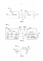
[009] A figura 1 é figura um diagrama de bloco funcional de um sistema de transferência de potência sem fio exemplar, de acordo com modalidades exemplares.[009] Figure 1 is a functional block diagram of an exemplary wireless power transfer system, according to exemplary embodiments.
[010] A figura 2 é um diagrama de bloco funcional de componentes exemplares que podem ser utilizados no sistema de transferência de potência sem fio da figura 1, de acordo com diversas modaldades exemplares.[010] Figure 2 is a functional block diagram of exemplary components that can be used in the wireless power transfer system of figure 1, according to several exemplary modalities.
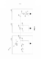
[011] A figura 3 é um diagrama esquemático de uma porção de circuito transmissor e circuito receptor da figura 2 incluindo uma bobina transmissora ou receptora, de acordo com modalidades exemplares.[011] Figure 3 is a schematic diagram of a portion of the transmitter circuit and receiver circuit of figure 2 including a transmitter or receiver coil, according to exemplary embodiments.
[012] A figura 4 é um diagrama de bloco funcional de um transmissor que pode ser usado no sistema de transferência de potência sem fio da figura 1, de acordo com modalidades exemplares.[012] Figure 4 is a functional block diagram of a transmitter that can be used in the wireless power transfer system of figure 1, according to exemplary modalities.
[013] A figura 5 é um diagrama de bloco funcional de um receptor que pode ser utilizado no sistema de transferência de potência sem fio da figura 1, de acordo com modalidades exemplares.[013] Figure 5 is a functional block diagram of a receiver that can be used in the wireless power transfer system of figure 1, according to exemplary modalities.
[014] A figura 6 é um diagrama esquemático de uma porção do circuito transmissor, que pode ser utilizado no circuito de transmissor da figura 4.[014] Figure 6 is a schematic diagram of a portion of the transmitter circuit, which can be used in the transmitter circuit of figure 4.
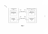
[015] A figura 7 é um diagrama de bloco de um sistema de carregamento sem fio que pode incorporar o circuito transmissor da figura 4 e o circuito receptor da FIG 5.[015] Figure 7 is a block diagram of a wireless charging system that can incorporate the transmitter circuit of Figure 4 and the receiver circuit of Figure 5.
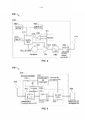
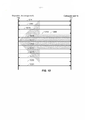
[016] A figura 8A é um diagrama de bloco de um serviço de carregamento e perfil para um sistema de carregamento sem fio, tal como o sistema de carregamento sem fio da figura 7.[016] Figure 8A is a block diagram of a charging service and profile for a wireless charging system, such as the wireless charging system in Figure 7.
[017] A figura 8B é um outro diagrama de bloco de um serviço de carregamento e perfil para um sistema de carregamento sem fio, tal como o sistema de carregamento sem fio da figura 7.[017] Figure 8B is another block diagram of a charging service and profile for a wireless charging system, such as the wireless charging system in Figure 7.
[018] A figura 9 é um diagrama de temporização de comunicações entre um carregador sem fio e um dispositivo de carregamento, tal como o carregador sem fio e o dispositivo de carregamento da figura 7, para estabelecer uma conexão entre o carregador sem fio e o dispositivo de carregamento.[018] Figure 9 is a communications timing diagram between a wireless charger and a charging device, such as the wireless charger and charging device of Figure 7, to establish a connection between the wireless charger and the charging device. charging device.
[019] A figura 10 é um diagrama de temporização de comunicações entre um carregador sem fio e um dispositivo de carregamento, tal como o carregador sem fio e o dispositivo de carregamento da figura 7, durante uma primeira conexão.[019] Figure 10 is a timing diagram of communications between a wireless charger and a charging device, such as the wireless charger and charging device of Figure 7, during a first connection.
[020] A figura 11 é um diagrama de temporização de comunicações entre um carregador sem fio e um dispositivo de carregamento, tal como o carregador sem fio e o dispositivo de carregamento da figura 7.[020] Figure 11 is a timing diagram of communications between a wireless charger and a charging device, such as the wireless charger and charging device of Figure 7.
[021] A figura 12 é um outro diagrama de temporização de comunicações entre um carregador sem fio e um dispositivo de carregamento, tal como o carregador sem fio e o dispositivo de carregamento da figura 7.[021] Figure 12 is another diagram of timing communications between a wireless charger and a charging device, such as the wireless charger and charging device of Figure 7.
[022] A figura 13 é um fluxograma de um método exemplar para a autenticação do dispositivo através de uma rede de comunicações sem fio de banda.[022] Figure 13 is a flowchart of an exemplary method for device authentication over an in-band wireless communications network.
[023] A figura 14 é um diagrama de bloco funcional de um carregador sem fio, de acordo com uma modalidade exemplar.[023] Figure 14 is a functional block diagram of a wireless charger, according to an exemplary embodiment.
[024] As diferentes características ilustradas nos desenhos não podem ser desenhadas à escala. Assim, as dimensões das diferentes características podem ser arbitrariamente expandidas ou reduzidas por razões de clareza. Além disso, alguns dos desenhos podem não representar todos os componentes de um dado sistema, método ou dispositivo. Finalmente, os mesmos números de referência podem ser utilizados para indicar características semelhantes ao longo da especificação e figuras.[024] The different features illustrated in the drawings cannot be drawn to scale. Thus, the dimensions of the different features can be arbitrarily expanded or reduced for clarity. Also, some of the drawings may not represent all components of a given system, method or device. Finally, the same reference numbers may be used to indicate similar features throughout the specification and figures.
[025] A descrição detalhada que segue abaixo em conexão com os desenhos anexos pretende ser uma descrição das modalidades exemplares e não se destina a representar as únicas modalidades nas quais a invenção pode ser praticada. O termo "exemplar" utilizado ao longo desta descrição significa "servir como um exemplo, uma circunstância ou ilustração", e não deve necessariamente ser interpretado como preferido ou vantajoso sobre outras modalidades exemplares. A descrição detalhada inclui detalhes específicos com a finalidade de prover uma compreensão completa das modalidades exemplares. Em alguns casos, alguns dispositivos são mostrados na forma de diagrama de bloco.[025] The detailed description which follows below in connection with the accompanying drawings is intended to be a description of exemplary embodiments and is not intended to represent the only embodiments in which the invention may be practiced. The term "exemplary" used throughout this description means "to serve as an example, circumstance or illustration", and should not necessarily be interpreted as preferred or advantageous over other exemplary embodiments. The detailed description includes specific details in order to provide a complete understanding of the exemplary modalities. In some cases, some devices are shown in block diagram form.
[026] Potência transferida sem fio pode se referir a qualquer forma de transferência de energia associada com campos elétricos, campos magnéticos, campos eletromagnéticos, ou de outro modo a partir de um transmissor para um receptor, sem a utilização de condutores elétricos físicos (por exemplo, a potência pode ser transferida através do espaço livre). A potência de saída num campo sem fio (por exemplo, um campo magnético) pode ser recebida, capturada por, ou acoplada através de uma "bobina de recepção" para conseguir a transferência de potência.[026] Wireless transferred power may refer to any form of energy transfer associated with electric fields, magnetic fields, electromagnetic fields, or otherwise from a transmitter to a receiver, without the use of physical electrical conductors (e.g. example, power can be transferred through free space). Output power in a wireless field (eg, a magnetic field) can be received, captured by, or coupled through a "receive coil" to achieve power transfer.
[027] figura 1 é um diagrama de bloco funcional de um sistema de transferência de potência sem fio exemplar 100, de acordo com modalidades exemplares. Entrada de potência 102 pode ser provida para um transmissor 104 de uma fonte de potência (não mostrada) para gerar um campo 105 para prover a transferência de potência. Um receptor 108 pode se acoplar ao campo 105 e gerar a saída de potência 110 para o armazenamento ou o consumo por um dispositivo (não mostrado) acoplado à potência de saída 110. Tanto o transmissor 104 quanto o receptor 108 são separados por uma distância 112. Em uma modalidade exemplar, o transmissor 104 e o receptor 108 são configurados de acordo com uma relação mútua de ressonância. Quando a frequência de ressonância do receptor 108 e a frequência de ressonância do transmissor 104 são substancialmente as mesmas ou muito próximas, as perdas de transmissão entre o transmissor 104 e o receptor 108 são mínimas. Como tal, a transferência de potência sem fio pode ser provida através de maior distância, em contraste com soluções puramente indutivas que podem exigir grandes bobinas que necessitam de bobinas para serem muito próximas (por exemplo, mms). Técnicas de acoplamento indutivo ressonantes podem, assim, permitir a melhoria da eficiência e transferência de potência em várias distâncias e com uma variedade de configurações de bobina indutiva.[027] Figure 1 is a functional block diagram of an exemplary wireless
[028] O receptor 108 pode receber potência quando o receptor 108 está localizado em um campo de energia 105 produzido pelo transmissor 104. O campo 105 corresponde a uma região onde a saída de energia pelo transmissor 104 pode ser captada por um receptor 105. Em alguns casos, o campo 105 pode corresponder ao "campo próximo" do transmissor 104, como será ainda descrito abaixo. O transmissor 104 pode incluir uma bobina transmissora 114 para a saída de transmissão de energia. O receptor 108 inclui ainda uma bobina receptora 118 para receber ou capturar energia a partir da energia de transmissão. O campo-próximo pode corresponder a uma região em que existam campos reativos fortes resultantes das correntes e cargas na bobina transmissora 114 que minimamente irradia potência afastada da bobina transmissora 114. Em alguns casos, o campo-próximo pode corresponder a uma região que está dentro de cerca de um comprimento de onda (ou de uma sua fração) da bobina transmissora 114. As bobinas de transmissão e recepção 114 e 118 são dimensionadas de acordo com as aplicações e dispositivos a ela associados. Tal como acima descrito, a transferência de energia eficiente pode ocorrer acoplando uma grande porção da energia de um campo 105 da bobina transmissora 114 para uma bobina receptora 118, em vez de propagar a maioria da energia de uma onda eletromagnética do campo distante. Quando posicionada dentro do campo 105, um modo de "acoplamento" pode ser desenvolvido entre a bobina transmissora 114 e a bobina receptora 118. A área em torno das bobinas de transmissoras e receptoras 114 e 118, onde pode ocorrer este acoplamento é aqui referida como uma região de modo de acoplamento.[028] The
[029] A figura 2 é um diagrama de bloco funcional de componentes exemplares que podem ser utilizados no sistema de transferência de potência sem fio 100 da figura 1, de acordo com diversas modalidades exemplares. O transmissor 204 pode incluir um circuito transmissor 206, que pode incluir um oscilador 222, um circuito condutor 224, e um filtro e um circuito correspondente 226. O oscilador 222 pode ser configurado para gerar um sinal com uma frequência desejada, como 468,75 KHz, 6,78 MHz ou de 13,56 MHz, que pode ser ajustada em resposta a um sinal de controle de frequência 223. O sinal do oscilador pode ser fornecido a um circuito condutor 224 configurado para dirigir a bobina transmissora 214, por exemplo, uma frequência de ressonância da bobina transmissora 214. O circuito condutor 224 pode ser um amplificador de comutação, configurado para receber uma onda quadrada a partir do oscilador 222 e uma onda sinusoidal de saída. Por exemplo, o circuito condutor 224 pode ser um amplificador de classe E. Um circuito de filtragem e correspondente 226 pode também ser incluído para filtrar frequências harmónicas ou outras indesejáveis e combinar a impedância do transmissor 204 para a bobina transmissora 214.[029] Figure 2 is a functional block diagram of exemplary components that can be used in the wireless
[030] O receptor 208 pode incluir circuito receptor 210, que pode incluir um circuito correspondente 232 e um circuito retificador e de comutação 234 para gerar uma saída de potência CC a partir de uma entrada de potência CA para carregar uma bateria 236, como mostrado na figura 2 ou para acionar um dispositivo (não mostrado) acoplado ao receptor 108. O circuito correspondente 232 pode ser incluído para combinar a impedância do circuito 210 para a bobina receptora 218. O receptor 208 e o transmissor 204 podem comunicar, adicionalmente, em um canal de comunicação separado 219 (por exemplo, Bluetooth, zigbee, celular, etc). O receptor 208 e o transmissor 204 podem comunicar, alternativamente, através de sinalização dentro da banda utilizando características do campo sem fio 206.[030]
[031] Tal como descrito mais completamente abaixo, o receptor 208, que pode ter uma carga inicialmente associada desabilitada seletivamente (por exemplo, bateria 236), pode ser configurado para determinar se uma quantidade de potência transmitida pelo transmissor 204 e recebida pelo receptor 208 é apropriada para carregar uma bateria 236. Além disso, o receptor 208 pode ser configurado para permitir uma carga (por exemplo, bateria 236) sobre a determinação de que a quantidade de potência é apropriada. Em algumas modalidades, um receptor 208 pode ser configurado para utilizar diretamente a potência recebida a partir do campo de transferência de potência sem fio sem o carregamento de uma bateria de 236. Por exemplo, um dispositivo de comunicação, tal como uma comunicação de campo-próximo (CNF) ou dispositivo de identificação por radiofrequência (DIRF) pode ser configurado para receber potência a partir de um campo de transferência de potência sem fio e comunicar através da interação com o campo de transferência de potência sem fio e/ou utilizar a potência recebida para comunicar com um transmissor 204 ou outros dispositivos.[031] As described more fully below,
[032] figura 3 é um diagrama esquemático de uma porção do circuito transmissor 206 ou circuito receptor 210 da figura. 2 incluindo uma bobina transmissora ou receptora 352, de acordo com modalidades exemplares. Tal como ilustrado na figura 3, circuito transmissor ou receptor 350 usado em modalidades exemplares podem incluir uma bobina 352. A bobina pode também ser referida ou ser configurado como uma antena de "loop" 352. A bobina 352 também pode ser referida, ou ser configurada como um antena “magnética” ou uma bobina de indução. O termo "bobina" se destina a se referir a um componente que pode receber ou colocar para fora energia sem fio, para o acoplamento a outra "bobina." A bobina pode também ser referida como uma "antena" de um tipo que está configurada para receber ou colocar para fora energia sem fio. A bobina 352 pode ser configurada para incluir um núcleo de ar, ou um núcleo físico tal como um núcleo de ferrite (não mostrado). Bobinas de loop de núcleo de ar podem ser mais aceitáveis para os dispositivos físicos estranhos colocados na proximidade do núcleo. Além disso, uma bobina de loop de núcleo de ar 352 permite a colocação de outros componentes dentro da área do núcleo. Além disso, uma bobina de núcleo de ar pode ser colocada mais facilmente na bobina receptora 218 (figura 2) dentro de um plano da bobina transmissora 214 (figura 2), onde a região de modo acoplada à bobina transmissora 214 (FIG 2) pode ser mais potente.[032] Figure 3 is a schematic diagram of a portion of the
[033] Como indicado, a transferência eficiente de energia entre o transmissor 104 e receptor 108 pode ocorrer durante a correspondência ou quase correspondência de ressonância entre o transmissor 104 e o receptor 108. No entanto, mesmo quando a ressonância entre o transmissor 104 e receptor 108 não é correspondida, a energia pode ser transferida, embora a eficácia possa ser afetada. Transferência de energia ocorre por acoplamento de energia a partir do campo 105 da bobina transmissora para a bobina receptora residente na vizinhança onde este campo 105 é estabelecido em vez de propagação da energia a partir da bobina transmissora no espaço livre.[033] As indicated, efficient energy transfer between
[034] A frequência de ressonância das bobinas magnética ou loop, é baseada na indutância e capacitância. Indutância pode ser simplesmente a indutância criada pela bobina 352, ao passo que, a capacitância pode ser adicionada a indutância da bobina para criar uma estrutura ressonante a uma frequência de ressonância desejada. Como um exemplo não limitante, o capacitor 352 e o capacitor 354 podem ser adicionados ao circuito transmissor e receptor 350 para criar um circuito ressonante que seleciona um sinal 356 a uma frequência de ressonância. Assim, para bobinas de maior diâmetro, o tamanho da capacitância necessária para sustentar a ressonância pode diminuir à medida que o diâmetro ou indutância do loop aumenta. Além disso, como o diâmetro da bobina aumenta, a área de transferência de energia eficiente do campo-próximo pode aumentar. Outros circuitos ressonantes formados usando outros componentes também são possíveis. Como um outro exemplo não limitativo, um capacitor pode ser colocado em paralelo entre os dois terminais da bobina 350. Para bobinas de transmissão, um sinal 358 com uma frequência que, substancialmente, corresponde à frequência ressonante da bobina 352 pode ser uma entrada para a bobina 352.[034] The resonant frequency of the magnetic or loop coils is based on inductance and capacitance. Inductance may simply be the inductance created by the
[035] Em uma modalidade, o transmissor 104 pode ser configurado para emitir um campo magnético de variação de tempo com uma frequência correspondente à frequência de ressonância da bobina transmissora 114. Quando o receptor está dentro do campo 105, o campo magneético de variação de tempo pode induzir uma corrente na bobina receptora 118. Como descrito acima, se a bobina receptora 118 está configurada para ser ressonante na frequência da bobina transmissora 118, a energia pode ser transferida de forma eficiente. O sinal CA induzido na bobina receptora 118 pode ser retificado, conforme descrito acima, para produzir um sinal CC que pode ser provido para carregar ou para acionar uma carga.[035] In one embodiment,
[036] figura 4 é um diagrama de bloco funcional de um transmissor 404, que pode ser usado no sistema de transferência de potência sem fio da figura 1, de acordo com modalidades exemplares. O transmissor 404 pode incluir um circuito transmissor 406 e uma bobina transmissora 414. A bobina transmissora 414 pode ser a bobina 352, como mostrada na figura 3. Circuito transmissor 406 pode prover energia RF para a bobina transmissora 414 através da provisão de um sinal oscilante, resultando na geração de energia (por exemplo, fluxo magnético) com a bobina transmissora 414. Transmissor 404 pode funcionar em qualquer frequência adequada. A título de exemplo, o transmissor 404 pode operar em banda 13,56 MHz ISM.[036] Figure 4 is a functional block diagram of a
[037] Circuito transmissor 406 pode incluir um circuito correspondente de impedância fixa 409 para correspondência de impedância do circuito transmissor 406 (por exemplo, 50 ohms) para a bobina transmissora 414 e um filtro passando baixo (LPF) 408 configurado para reduzir as emissões harmónicas a níveis para evitar o auto bloqueio de dispositivos acoplados a receptores 108 (figura 1). Outras modalidades exemplares podem incluir diferentes topologias de filtro, incluindo mas não se limitando a, filtros de entalhe que atenuam as frequências específicas durante a passagem e outros podem incluir uma correspondência de impedância de adaptação, que pode variar baseada em parâmetros mensuráveis de transmissão, tais como a e potência de saída para a bobina 414 ou CC corrente desenhada pelo circuito condutor 424. Circuito transmissor 406 inclui ainda um circuito condutor 424 configurado para conduzir um sinal RF, conforme determinado por um oscilador 423. O circuito transmissor 406 pode ser compreendido por dispositivos ou circuitos discretos, ou alternativamente, pode ser compreendido por um conjunto integrado. Uma saída de potência RF exemplar da bobina transmissora 414 pode ser da ordem de 2,5 Watts.[037]
[038] Circuito transmissor 406 pode incluir ainda um controlador 415 para ativar seletivamente o oscilador 423, durante as fases de transmissão (ou ciclos de trabalho) para receptores específicos, para ajustar a frequência ou fase do oscilador 423, e para ajustar o nível de potência de saída para execução de um protocolo de comunicação para interagir com os dispositivos vizinhos através de seus receptores ligados. É notado que o controlador 415 também pode ser referido como processador 415. Ajuste de fase do oscilador e circuitos relacionados no caminho de transmissão pode permitir a redução de emissões de banda, especialmente quando a transacionando de uma frequência para outra.[038]
[039] O circuito transmissor 406 pode ainda incluir um circuito de sensor de carga 416 para detectar a presença ou ausência de receptores ativos na vizinhança do campo- próximo gerado pela bobina transmissora 414. A título de exemplo, um circuito de sensor de carga 416 monitora a corrente que flui para o circuito condutor 424, que pode ser afetada pela presença ou ausência de receptores ativos na vizinhança do campo gerado pela bobina transmissora 414, como será ainda descrito abaixo. A detecção de alterações na carga do circuito de condução 424 são monitoradas pelo controlador 415 para uso em determinar se é necessário ativar o oscilador 423 para transmissão de energia e para se comunicar com um receptor ativo. Como descrito mais detalhadamente abaixo, uma corrente medida no circuito de condução 424 pode ser utilizada para determinar se um dispositivo inválido é posicionado dentro de uma região de transferência de potência sem fio do transmissor 404.[039] The
[040] A transmissão da bobina 414 pode ser implementada com um fio Litz, ou como uma tira de antena com a espessura, largura e tipo de metal selecionado para manter as perdas resistivas baixas. Em uma implementação, a bobina transmissora 414 geralmente pode ser configurada para a associação com uma estrutura maior, tais como uma tabela, esteira, lâmpada ou outra configuração menos portátil. Assim, a bobina transmissora 414 geralmente pode não precisa de "voltas", a fim de ser de uma dimensão prática. Uma implementação exemplar de uma bobina transmissora 414 pode ser "eletricamente pequena" (ou seja, fração do comprimento de onda) e ajustada para ressoar a frequências inferiores utilizáveis usando capacitores para definir a freqüência de ressonância.[040] The transmission of the 414 coil can be implemented with a Litz wire, or as an antenna strip with the thickness, width and type of metal selected to keep resistive losses low. In one implementation, the
[041] O transmissor 404 pode recolher e rastrear informações sobre a localização e estado de dispositivos receptores que podem estar associados com o transmissor 404 Assim, o circuitos de transmissão 406 pode incluir um detector de presença de 480, um detector de fechamento 460, ou uma combinação dos mesmos, ligado ao controlador 415 (também referido como um processador). O controlador 415 pode ajustar a quantidade de energia fornecida pelo circuito condutor 424, em resposta a sinais de presença do detector de presença 480 e o detector de fechamento 460. O transmissor 404 pode receber energia através de um número de fontes de energia, tais como, por exemplo, um conversor CA-CC (não mostrado) para converter energia CA convencional presente numa construção, um conversor CC-CC (não mostrado) para converter uma fonte de energia CC convencional para uma tensão apropriada para o transmissor 404, ou diretamente a partir de uma fonte de energia CC convencional (não mostrada).[041]
[042] Como exemplo não limitante, o detector de presença 480 pode ser um detector de movimento utilizado para detectar a presença inicial de um dispositivo para ser carregado, que é inserido para dentro da área de cobertura do transmissor 404. Após a detecção, o transmissor 404 pode ser ligado e a energia RF recebida pelo dispositivo pode ser usada para alternar um interruptor no dispositivo Rx de uma forma pré-determinada, que por sua vez resulta em alterações na impedância do ponto de condução do transmissor 404.[042] As a non-limiting example, the
[043] Como outro exemplo não limitativo, o detector de presença 480 pode ser um detector capaz de detectar um ser humano, por exemplo, por detecção de infravermelhos, detecção de movimento, ou por outros meios adequados. Em algumas modalidades exemplares, podem haver regulamentos que limitam a quantidade de energia que uma bobina transmissora 414 pode transmitir a uma frequência específica. Em alguns casos, estes regulamentos são feitos para proteger os seres humanos da radiação eletromagnética. No entanto, pode haver ambientes onde uma bobina transmissora 414 é colocada em áreas não ocupadas por seres humanos, ou raramente ocupadas por seres humanos, tais como, por exemplo, garagens, chão de fábrica, lojas, e similares. Se esses ambientes estão livres de seres humanos, pode ser possível aumentar a energia de saída da bobina transmissora 414 acima do nível de controle de restrições de energia normais. Em outras palavras, o controlador 415 pode ajustar a energia de saída da bobina transmissora 414 a um nível de regulação ou abaixo em resposta à presença humana e ajustar a energia de saída da bobina transmissora 414 a um nível acima do nível de controle quando um ser humano está fora uma distância regulamentar do campo eletromagnético da bobina transmissora 414.[043] As another non-limiting example, the
[044] Como exemplo não limitante, o detector fechado 460 (pode também ser referido como um detector de compartimento fechado, ou um detector de espaço fechado) pode ser um dispositivo, tal como um comutador de sentido para determinar quando um compartimento está em estado fechado ou aberto. Quando um transmissor está em um compartimento que está em um estado fechado, um nível de energia do transmissor pode ser aumentado.[044] As a non-limiting example, the closed detector 460 (may also be referred to as an enclosure detector, or an enclosure detector) may be a device, such as a direction switch, for determining when a compartment is in a state closed or open. When a transmitter is in a compartment that is in a closed state, a transmitter power level can be increased.
[045] Em modalidades exemplares, um método em que cada transmissor 404 não continua indefinidamente pode ser usado. Neste caso, o transmissor 404 pode ser programado para desligar após um período determinado, pelo usuário, de tempo. Este recurso evita que o transmissor 404, particularmente o circuito de condução 424, de correr muito depois dos dispositivos sem fio em seu perímetro estão completamente carregados. Este evento pode ser devido a uma falha do circuito para detectar o sinal enviado a partir de qualquer um repetidor ou da bobina receptora que um dispositivo está totalmente carregado. Para prevenir que o transmissor 404 desligue automaticamente se outro dispositivo é colocado em seu perímetro, o transmissor 404 recurso de desligamento automático pode ser ativado apenas após um período de ausência de movimento detectado no seu perímetro. O usuário pode ser capaz de determinar o tempo de inatividade, e alterá-lo como desejar. Como um exemplo não limitante, o intervalo de tempo pode ser mais longo do que o necessário para carregar totalmente um tipo específico de dispositivo sem fio sob a suposição de que o dispositivo seja inicialmente totalmente descarregado.[045] In exemplary embodiments, a method in which each
[046] A figura 5 é um diagrama de bloco funcional de um receptor 508, que pode ser usado no sistema de transferência de energia sem fio da figura 1, de acordo com modalidades exemplares. O receptor 508 inclui circuitos de recepção 510 que podem incluir uma bobina receptora 518. Receptor 508 ainda acopla ao dispositivo 550 para fornecer energia recebida da mesma. Deve ser notado que o receptor 508 é ilustrado como sendo externo ao dispositivo 550, mas pode ser integrado no dispositivo 550. Energia pode ser propagada sem fio para a bobina receptora 518 e, em seguida, acoplada com o restante dos circuitos de recepção 510 do dispositivo 550. A título de exemplo, o dispositivo de carregamento pode incluir dispositivos como telefones celulares, tocadores de música portáteis, computadores portáteis, tablets, dispositivos periféricos de computadores, dispositivos de comunicação (por exemplo, dispositivos de Bluetooth), câmeras digitais, aparelhos auditivos (e outros dispositivos médicos), e similares.[046] Figure 5 is a functional block diagram of a
[047] Bobina receptora 518 pode ser ajustada para ressoar na mesma freqüência, ou dentro de um determinado intervalo de frequências, como bobina transmissora 414 (figura 4). Bobina receptora 518 pode ser dimensionada de forma semelhante, com a bobina transmissora 414 ou pode ser dimensionada de modo diferente baseada nas dimensões do dispositivo associado 550 A título de exemplo, o dispositivo 550 pode ser um dispositivo eletrónico portátil tendo dimensões de diâmetro e comprimento menores que o diâmetro de comprimento da bobina transmissora 414. Como exemplo, a bobina receptora 518 pode ser implementada como uma bobina de multi voltas, a fim de reduzir o valor de capacitância de um capacitor de ajuste (não mostrado) e aumentar a impedância da bobina de recepção. A título de exemplo, a bobina receptora 518 pode ser colocada em torno da circunferência substancial do dispositivo 550, a fim de maximizar o diâmetro da bobina e reduzir o número de voltas de loop (ou seja, enrolamentos) da bobina receptora 518 e a capacitância do inter enrolamento.[047]
[048] Circuito receptor 510 pode prover uma correspondência de impedância para bobina receptora 518. Circuito receptor 510 inclui um circuito de conversão de energia 506 para conversão de uma fonte de energia RF recebida na energia de carga para utilização pelo dispositivo 550. Circuito de conversão de energia 506 inclui um conversor RF para CC 520 e também pode incluir um conversor CC para CC 522. Conversor RF para CC 520 retifica o sinal de energia RF recebido na bobina receptora 518 em uma energia não alternada com uma tensão de saída representada por Vrect. O conversor CC para CC 522 (ou outro regulador de energia) converte o sinal de energia RF retificado em um potencial de energia (por exemplo, tensão), que é compatível com o dispositivo 550 com uma tensão de saída e corrente de saída representada por Vout e Iout. Vários conversores RF para CC estão contemplados, incluindo retificadores parcial e total, reguladores, pontes, duplicadores, assim como conversores lineares e comutação.[048]
[049] Circuito receptor 510 pode ainda incluir circuito de comutação 512 para conectar bobina receptora 518 para o circuito de conversão de energia 506 ou, alternativamente, para desconectcar o circuito de conversão de energia 506. Desconectando a bobina receptora 518 do circuito de conversão de energia 506 não somente suspende o carregamento do dispocitivo, mas também muda o “carregamento” como “visto” pelo trasmissor 404. (figura 2).[049]
[050] Como descrito acima, o transmissor 404 inclui o circuito de sensor de carga 416 que pode detectar flutuações na corrente de polarização provida ao circuito de condução transmissor 424. Assim, o transmissor 404 tem um mecanismo para determinar quando os receptores estão presentes no campo-próximo do transmissor.[050] As described above,
[051] Quando vários receptores 508 estão presentes no campo-próximo do transmissor, isto pode ser desejável para multiplexar o tempo de carga e descarga de um ou mais receptores para ativar outros receptores para acoplar de forma mais eficiente o transmissor. Um receptor 508 pode também ser revestido de modo a eliminar o acoplamento a outros receptores próximos ou para reduzir a carga nos transmissores vizinhos. Esta "descarga" de um receptor é também conhecida como "camuflagem". Além disso, esta comutação entre descarregamento e carregamento controlada pelo receptor 508 e detectada pelo transmissor 404 pode prover um mecanismo de comunicação do receptor 508 para o transmissor 404 como é explicado mais detalhadamente abaixo. Além disso, um protocolo pode ser associado com a comutação que permite o envio de uma mensagem do receptor 508 para o transmissor 404. A título de exemplo, uma velocidade de comutação pode ser da ordem de 100 μseg.[051] When multiple 508 receivers are present in the near field of the transmitter, it may be desirable to multiplex the load and unload time of one or more receivers to activate other receivers to more efficiently couple the transmitter. A 508 receiver may also be coated to eliminate coupling to other nearby receivers or to reduce the load on neighboring transmitters. This "discharge" from a receiver is also known as "cloaking". Furthermore, this switching between offloading and loading controlled by the
[052] Em uma modalidade exemplar, a comunicação entre o transmissor 404 e o receptor 508 se refere a um dispositivo de detecção de carga e mecanismo de controle, em vez de uma comunicação de duas vias convencionais (ou seja, na sinalização através do campo de acoplamento da banda). Em outras palavras, o transmissor 404 pode usar o código de ligar/desligar do sinal transmitido para ajustar quando a energia estiver disponível no campo-próximo. O receptor pode interpretar essas mudanças na energia como uma mensagem do transmissor 404. Do lado do receptor, o receptor 508 pode usar sintonização e desintonização da bobina receptora 518 para ajustar o quanto de energia está sendo aceito a partir do campo. Em alguns casos, a sintonização e desintonização podem ser obtidas através do circuito de comutação 512. O transmissor 404 pode detectar esta diferença na energia utilizada do campo e interpretar estas mudanças como uma mensagem do receptor 508. É notado que outras formas de modulação da energia de transmissão e o comportamento da carga podem ser utilizadas.[052] In an exemplary embodiment, the communication between the
[053] Circuito receptor 510 pode ainda incluir detector de sinalização e circuito balizador 514 usado para identificar as flutuações de energia recebidas, que podem corresponder a sinalização informacional a partir do transmissor para o receptor. Além disso, o circuito de sinalização e balizador 514 podem também ser utilizados para detectar de um reduzido sinal de energia RF (isto é, um sinal balizador) e para retificar a redução do sinal de energia RF em uma potência nominal para despertar ambos circuitos com potência ou com potência esgotada dentro do circuito receptor 510, a fim de configurar o circuito receptor 510 para carregamento sem fio.[053]
[054] Circuito receptor 510 inclui ainda processador 516 para coordenar os processos do receptor 508 descritos, incluindo o controle de comutação de circuito 512 descrito. Camuflagem do receptor 508 também pode ocorrer quando da ocorrência de outros eventos, incluindo a detecção de uma fonte com fio de carregamento externo (por exemplo, a parede/USB de energia) provendo energia para o carregamento do dispositivo 550. Processor 516, além de controlar a camuflagem do receptor, pode também monitorar circuito balizador 514 para determinar um estado balizador e extrair as mensagens enviadas a partir do transmissor 404. Processador 516 também pode ajustar o conversor CC para CC 522 para melhorar o desempenho.[054]
[055] figura 6 é um diagrama esquemático de uma porção de um circuito transmissor 600 que pode ser utilizado no circuito transmissor 406 da figura 4. O circuito transmissor 600 pode incluir um circuito condutor 624, conforme descrito acima na figura 4. Como descrito acima, o circuito condutor 624 pode ser um amplificador de comutação, que pode ser configurado para receber uma onda quadrada e de saída de uma onda sinusoidal a ser fornecida para o circuito transmissor 650. Em alguns casos, o circuito condutor 624 pode ser referido como um circuito amplificador. O circuito condutor 624 é mostrado como um amplificador de classe E, no entanto, qualquer circuito condutor 624 adequado pode ser utilizado de acordo com as modalidades. O circuito condutor 624 pode ser acionado por um sinal de entrada 602 de um oscilador 423 como mostrado na figura 4. O circuito condutor 624 pode também ser provido com uma tensão condutora VD que está configurada para controlar a potência máxima que pode ser fornecida através de um circuito transmissor 650. Para eliminar ou reduzir os harmónicos, o circuito transmissor 600 pode incluir um circuito de filtro 626. O circuito de filtro 626 pode ser um tripolar (capacitor 634, indutor 632, e capacitor 636) circuito de filtro de passagem baixa 626.[055] Figure 6 is a schematic diagram of a portion of a
[056] O sinal de saída pelo circuito de filtro 626 pode ser provido para um circuito transmissor 650 compreendendo uma bobina 614. O circuito transmissor 650 pode incluir um circuito de ressonância em série tendo uma capacitância 620 e indutância (por exemplo, que pode ser devido à indutância ou capacitância da bobina ou de um componente adicional do capacitor), que podem ressoar a uma frequência do sinal filtrado provido pelo circuito condutor 624. A carga do circuito transmissor 650 pode ser representado pela resistência variável 622. A carga pode ser uma função de um receptor de potência sem fio 508 que está posicionado para receber potência a partir do circuito transmissor 650.[056] The output signal by
[057] figura 7 é um diagrama de bloco de um sistema de carregamento sem fio 700, que pode incorporar o circuito transmissor 406 da figura 4 e o circuito receptor 510 da figura 5. O sistema de carregamento sem fio 700 pode compreender um carregador sem fio 702 e um dispositivo de carregamento 704. O carregador sem fio 702 pode incluir um transmissor de potência sem fio 710 e um transceptor Bluetooth 720. Em uma modalidade, o transmissor de potência sem fio 710 pode ser semelhante a e/ou incluir a mesma funcionalidade que o circuito transmissor 406 da figura 4. O dispositivo de carregamento 704 pode ser semelhante ao dispositivo de carregamento 550 da figura 5 e ainda inclue um receptor de potência sem fio 715 e um transceptor Bluetooth 725. Em uma modalidade, o receptor de potência sem fio 715 pode ser semelhante a e/ou incluir a mesma funcionalidade que o circuito receptor 510 da figura 5.[057] Figure 7 is a block diagram of a
[058] O transmissor de potência sem fio 710 pode ser acoplado a uma bobina transmissora 714. A bobina transmissora 714 pode ser semelhante à bobina transmissora 414 da figura 4. Do mesmo modo, o receptor de potência sem fio 715 pode ser acoplado a uma bobina receptora 718. A bobina receptora 718 pode ser semelhante à bobina receptora 518 da figura 5. Em uma modalidade, o transmissor de potência sem fio 710 pode ser configurado para transmitir potência sem fio para o receptor de potência sem fio 715 para carregar o dispositivo de carregamento 704.[058] Wireless power transmitter 710 may be coupled to a
[059] O transceptor de Bluetooth 720 pode ser acoplado à antena de Bluetooth 724 e o transceptor de Bluetooth 725 pode ser acoplado à antena de Bluetooth 728. Em uma modalidade, os transceptores de Bluetooth 720 e 725, através de antenas 724 e 728, podem ser utilizados para estabelecer um conexão entre o carregador sem fio 702 e o dispositivo de carregamento 704 de modo que o dispositivo de carregamento 704 possa receber potência sem fio a partir do carregador sem fio 702, a fim de carregar a bateria ou dispositivo semelhante. Note que, embora o uso do protocolo de Bluetooth para estabelecer uma conexão entre o carregador sem fio 702 e o dispositivo de carregamento 704, é descrito, isto não pretende ser limitativo. Aspectos da divulgação como descritos podem ser implementados através da utilização de um protocolo de comunicação com ou sem fio (por exemplo, um protocolo de comunicação de propriedade, um protocolo de comunicação estabelecido por uma organização de padrões, como IEEE, etc). Por exemplo, IrDA, USB Sem Fio, Z-Wave, ZigBee, USB, Firewire, e/ou semelhantes podem ser utilizados.[059] The
[060] A figura 8A é um diagrama de bloco de um serviço de carregamento e perfil 800, para um sistema de carregamento sem fio, tal como o sistema de carregamento sem fio 700 da figura 7. Em uma modalidade, o serviço de carregamento e perfil 800 compreende um carregador sem fio 802 e um dispositivo de carregamento 804. O carregador sem fio 802 pode ser semelhante a um carregador sem fio 702 da figura 7 e o dispositivo de carregamento 804 pode ser semelhante ao dispositivo de carregamento 704 da figura 7. O carregador sem fio 802 pode incluir um processador 810 que está configurado para operar um perfil de carregamento 815. Em alguns aspectos, o perfil de carregamento 815 é um cliente de perfil de atributo genérico cliente (GATT) usando o transporte de Baixa Energia de Bluetooth (BLE), onde o GATT estabelece operações comuns e um enquadramento para os dados transportados e armazenados por um protocolo de atributo. Em geral, o GATT é usado para serviços de descoberta.[060] Figure 8A is a block diagram of a charging service and
[061] O dispositivo de carregamento 804 pode operar em dois modos: um modo de auto-potência e um modo de potência por carregador. Em um modo de auto-potência, o dispositivo de carregamento 804 contém potência suficiente (por exemplo, carga suficiente remanescente na bateria ou outra fonte de potência interna) para operar num modo normal durante o carregamento. Em um modo de potência por carregador, o dispositivo de carregamento 804 não tem energia suficiente para operar no modo normal e requerer potência do carregador sem fio 802 para se alimentar para apoiar uma operação de carregamento.[061] The 804 charging device can operate in two modes: a self-powered mode and a per-charger power mode. In a self-powered mode, the charging
[062] O dispositivo de carregamento 804 pode incluir um processador 820 que está configurado para operar em serviço de carregamento 825 Em alguns aspectos, o serviço de carregamento 825 é um servidor GATT usando o transporte BLE, onde um servidor GATT armazena os dados transportados sobre o protocolo de atributo e pedido de protocolo de atributo de acesso, comandos e confirmações a partir do cliente GATT. Em uma modalidade, o serviço de carregamento 825 pode interagir com o perfil de carregamento 815 quando o dispositivo de carregamento 804 está operando num modo de auto-potência. Por exemplo, o dispositivo de carregamento 804, em um modo de auto-potência pode ter carga suficiente remanescente na bateria de forma que um dispositivo como o processador 820, que pode usar mais energia do que outros componentes, como um conjunto de chips, pode ser alimentado. Em outras modalidades, o serviço de carregamento 825 pode interagir com o perfil de carregamento 815 quando o dispositivo de carregamento 804 está operarando num modo de potência de carregamento.[062]
[063] O dispositivo de carregamento 804 pode também incluir um conjunto de chips, tal como um conjunto de chips de Bluetooth 830, que está configurada para operar em serviço de carregamento 835. Em alguns aspectos, o serviço de carregamento 835 é um servidor GATT. Em uma modalidade, o serviço de carregamento 835 pode interagir com o perfil de carregamento 815 quando o dispositivo de carregamento 804 está operando num modo de potência por carregador. Por exemplo, o dispositivo de carregamento 804, em um modo de potência por carregador pode não ter carga suficiente para alimentar todos os seus componentes, como o processador 820. Como uma maneira de conservar a potência, usando a potência recebida a partir do carregador sem fio 802, apenas o conjunto de chips de Bluetooth 830 pode ser alimentado. Em outras modalidades, o serviço de carga 835 pode interagir com o perfil de carregamento 815 quando o dispositivo de carregamento 804 está operando num modo de auto-potência. Em outras palavras, o dispositivo de carregamento 804 pode incluir, pelo menos, dois servidores do GATT, cada implementação de um serviço de carregamento diferente 825 ou 835, e cada servidor pode incluir uma instância de um serviço de carregamento WiPower (WPCS) e uma instância de um serviço de informação do dispositivo (DIS).[063] Charging
[064] Embora a figura 8A mostre o conjunto de chip 830 como sendo um conjunto de chip de Bluetooth, deve se notar que este não se destina a ser um fator limitante e o conjunto de chip 830 pode ser projetado para lidar com qualquer protocolo de comunicações sem fio. Em ainda outras modalidades, o serviço de carregamento 825 e/ou 835 pode ser incorporado em um acessório para o dispositivo de carregamento 804, tal como um dispositivo externo ou uma pele.[064] Although Figure 8A shows the 830 chip set as being a Bluetooth chip set, it should be noted that this is not intended to be a limiting factor and the 830 chip set can be designed to handle any communication protocol. wireless communications. In still other embodiments, the charging service 825 and/or 835 may be incorporated into an accessory for the
[065] A figura 8B é um outro diagrama de bloco de um serviço de carga e perfil 850 para um sistema de carregamento sem fio, tal como o sistema de carregamento sem fio 700 da figura 7. Em uma modalidade, o dispositivo de carregamento 804 pode incluir um conjunto de chips, tal como um conjunto de chips de Bluetooth 830, que está configurado para utilizar os serviços de carregamento 825 e 835. O serviço de carregamento 825 pode ser usado para interagir com o perfil de carregamento 815 quando a dispositivo de carregamento 804 está num modo de auto- potência e o serviço de carregamento 835 pode ser usado para interagir com o perfil de carregamento 815 quando o dispositivo de carregamento 804 for um modo de potência por carregador. Alternativamente, o serviço de carregamento 825 pode ser usado para interagir com o perfil de carregamento 815 quando o dispositivo de carregamento 804 for um modo de potência por carregador e o serviço de carregamento 835 pode ser usado para interagir com o perfil de carregamento 815 quando o dispositivo de carregamento 804 está no modo de auto-potência. Em outras modalidades, um processador, tal como o processador 820 da figura 8A, pode ser configurado para operar os serviços de carregamento 825 e 835. Em outras palavras, o dispositivo de carregamento 804 pode incluir um servidor GATT que implementa pelo menos dois serviços de carregamento diferentes 825 ou 835, e o servidor GATT pode incluir um exemplo de um WPCS e um exemplo de um DIS.[065] Figure 8B is another block diagram of a charging service and
[066] A figura 9 é um diagrama de temporização de comunicações entre um carregador sem fio e um dispositivo de carregamento, tal como o carregador sem fio 702 e o dispositivo de carregamento 704, para estabelecer uma conexão entre o carregador sem fio e o dispositivo de carregamento. O carregador sem fio 702 pode transmitir um impulso de potência 902, onde o impulso de potência 902 pode ser usado para fornecer potência a um dispositivo de carregamento, como o dispositivo de carregamento 704, para carregar o dispositivo de carregamento. O carregador sem fio 702 pode transmitir o impulso de potência 902 a fim de detectar um dispositivo de carregamento. Tal como ilustrado na figura 9, o impulso de potência 902 foi transmitido, mas sem dispositivo de carregamento no alcance de impulso de potência 902. O carregador sem fio 702 pode esperar um período de tempo antes de transmitir um outro impulso de potência 904, por exemplo, o carregador sem fio 702 pode esperar 11,25ms ou 22,5 ms. Após a transmissão do impulso de potência 902 e/ou 904, o carregador sem fio 702 pode iniciar um procedimento geral de estabelecimento da conexão. Tal como ilustrado na figura 9, o impulso de potência 904 foi transmitido e dentro do alcance do dispositivo de carregamento 704.[066] Figure 9 is a diagram of timing communications between a wireless charger and a charging device, such as
[067] Uma vez que o carregador sem fio 702 detectar uma carga no impulso de potência 904, o carregador sem fio 702 inicia a busca de aviso (por exemplo, uma solicitação de conexão) a partir de um dispositivo, como o dispositivo de carregamento 704. Deste modo, o carregador sem fio 702 pode economizar potência apenas por buscar por aviso, uma vez que detecta uma carga no impulso de potência. Em uma modalidade, o impulso de potência 904 faz com que o dispositivo de carregamento 704 para gerar um aviso (por exemplo, um processador de dispositivo de carregamento 704 pode gerar o aviso). O aviso pode incluir um endereço de dispositivo de destino e um tipo de serviço de carregamento. Como um exemplo, o aviso pode ser um aviso BLE 906. O dispositivo de carregamento 704 pode transmitir o aviso BLE 906 (por exemplo, como uma mensagem transmitida) com o carregador sem fio 702, como o destinatário pretendido. Se o aviso BLE 906 não alcança o carregador sem fio 702 (como representado na figura 9.), então, o dispositivo de carregamento 704 pode gerar e transmitir um outro aviso BLE 908. Por exemplo, o dispositivo de carregamento 704 pode esperar 20ms antes de enviar outro aviso BLE 908. Se a conexão não for estabelecida dentro de um determinado período de tempo, como 10 segundos, o dispositivo de carregamento 704 pode sair de um modo conectável e parar qualquer carregamento que pode ter começado. Desta forma, o dispositivo de carregamento 704 pode economizar potência apenas por gerar e transmitir um anúncio BLE 906 e/ou 908, uma vez que ele recebe um impulso de potência 902 e/ou 904 a partir do carregador sem fio 702.[067] Once the
[068] Uma vez que o carregador sem fio 702 recebe o anúncio BLE 908, o carregador sem fio pode transmitir um pedido de conexão 912 para o dispositivo de carregamento 704. Se o dispositivo de carregamento 704 aceita a solicitação de conexão 912, uma conexão 914 é estabelecida entre o carregador sem fio 702 e 704 a partir do dispositivo de carregamento.[068] Once the
[069] Note que durante o processo de conexão ilustrado na figura 9, o carregador sem fio 702 pode continuar a transmitir potência 910, tal como através do impulso de potência 902 e/ou 904, a fim de carregar o dispositivo de carregamento 704. Em alguns aspectos, o dispositivo de carregamento 704 pode ser em um modo de potência por carregador, e a potência 910 iria permitir que o dispositivo de carregamento 704 se mantenha ativo a fim de estabelecer uma conexão com o carregador sem fio 702 uma vez que o carregador sem fio 702 determina que uma conexão não pode ser estabelecida, que o dispositivo de carregamento 704 é agora em um modo de auto-potência, e/ou que o dispositivo de carregamento 704 de outro modo não é necessário a potência transmitida a partir do carregador sem fio 702, então o carregador sem fio 702 pode parar de transmitir a potência 910.[069] Note that during the connection process illustrated in Figure 9, the
[070] Se a conexão for perdida, a qualquer momento, o dispositivo de carregamento 704 pode tentar se reconectar com o carregador sem fio 702. Alternativamente, o dispositivo de carregamento 704 pode esperar até receber outro impulso de potência 902 e/ou 904 a partir do carregador sem fio 702.[070] If the connection is lost, at any time the
[071] A figura 10 é um diagrama de temporização de comunicações entre um carregador sem fio e um dispositivo de carregamento, tal como o carregador sem fio 702 e o dispositivo de carregamento 704 da figura 7, durante uma primeira conexão. Em uma modalidade, as seguintes comunicações podem ocorrer durante uma primeira conexão, independentemente do fato de o dispositivo de carregamento estar operarando num modo de auto-potência ou um modo de potência por carregador. Depois que uma conexão 914 é estabelecida entre o carregador sem fio 702 e o dispositivo de carregamento 704, o carregador sem fio 702 pode autenticar o dispositivo de carregamento 704 para garantir que o dispositivo de carregamento 704 seja compatível com o carregador através de um procedimento BLE de autenticação/criptografia/ligação 1002. O procedimento BLE de autenticação/criptografia/ligação 1002 está descrito em mais detalhes com referência às FIGS. 11 e 12.[071] Figure 10 is a timing diagram of communications between a wireless charger and a charging device, such as the
[072] Após a autenticação, o carregador sem fio 702 pode descobrir um serviço primário, transmitindo um pedido identificador único universal (UUID) 1004. Por exemplo, a solicitação UUID 1004 pode ser usada para descobrir um WPCS primário. O dispositivo de carregamento 704 pode responder com uma resposta UUID 1006 O carregador sem fio 702 pode, então, descobrir algumas ou todas as características de um serviço pela transmissão de um pedido de serviço 1008. Por exemplo, a solicitação de serviço 1008 pode ser usada para descobrir algumas ou todas as características de um WPCS. O dispositivo de carregamento 704 pode responder com uma resposta de serviço 1012.[072] After authentication,
[073] O carregador sem fio 702 pode, então, descobrir um serviço primário pela transmissão de um pedido UUID 1014. Por exemplo, a solicitação UUID 1014 pode ser usada para descobrir um DIS primário. O dispositivo de carregamento 704 pode responder com uma resposta UUID 1016. O carregador sem fio 702 pode, então, descobrir algumas ou todas as características de um serviço pela transmissão de um pedido de serviço 1018. Por exemplo, a solicitação de serviço 1018 pode ser utilizada para descobrir algumas ou todas as características de uma DIS. O dispositivo de carregamento 704 pode responder com uma resposta de serviço 1020.[073]
[074] Note que durante o primeiro processo de conexão ilustrado na figura 10, o carregador sem fio 702 pode continuar a transmitir potência 1010, a fim de carregar o dispositivo de carregamento 704. Em alguns aspectos, o dispositivo de carregamento 704 pode ser um modo de potência por carregador, e a potência 1010 iria permitir que o dispositivo de carregamento 704 permaneça ativo, a fim de estabelecer uma conexão com o carregador sem fio 702 uma vez que o carregador sem fio 702 determina que uma ligação foi terminada e/ou que o dispositivo de carregamento 704 de outro modo não precisa da potência transmitida sem fio a partir do carregador sem fio 702, então o carregador sem fio 702 pode parar de transmitir a potência 1010.[074] Note that during the first connection process illustrated in Figure 10,
[075] A figura 11 é um diagrama de temporização de comunicações entre um carregador sem fio e um dispositivo de carregamento, tal como o carregador sem fio 702 e o dispositivo de carregamento 704 da figura 7. Em uma modalidade, as seguintes comunicações podem ocorrer quando o dispositivo de carregamento 704 está operando num modo de auto-potência. Depois de uma conexão 914 ser estabelecida entre o carregador sem fio 702 e o dispositivo de carregamento 704, o carregador sem fio 702 pode autenticar o dispositivo de carregamento 704 para garantir que o dispositivo de carregamento 704 é compatível com o carregador utilizando um protocolo de resposta de objeção durante o transporte BLE (por exemplo, através de um procedimento BLE de autenticação/criptografia 1102).[075] Figure 11 is a timing diagram of communications between a wireless charger and a charging device, such as the
[076] O carregador sem fio 702 pode transmitir uma gravação sem valor (autenticar WPT) de resposta 1104 para o dispositivo de carregamento 704. Em uma modalidade, baseada no valor recebido, o dispositivo de carregamento 704 pode gerar um valor de código e transmitir o valor de código ao carregador sem fio 702 através de resposta de resposta de valor (autenticar WPT) de notificação 1106. em outras modalidades, baseadas no valor recebido, o dispositivo de carregamento 704 pode transmitir um valor de código armazenado ou incorporado no dispositivo de carrgamento 704 para o carregador sem fio 702 através de uma resposta de valor (autenticar WPT) de notificação 1106. o valor do código pode ser um código público, um código privado, um certificado de código público, uma assinatura digital, um token de segurança, um identificador único do fabricante, ou algo semelhante. Se o valor do código corresponde ao valor esperado pelo carregador sem fio 702, então a autenticação é concluída e o carregador sem fio 702 determinou que o dispositivo de carregamento 704 é compatível com ele.[076]
[077] Em outros aspectos, o carregador sem fio 702 pode se envolver em uma ou mais comunicações com o dispositivo de carregamento 704 para garantir que o dispositivo de carregamento 704 é compatível com o carregador 702. O carregador sem fio 702 pode transmitir uma ou mais mensagens de autenticação para o dispositivo de carregamento 704. Se uma ou mais respostas recebidas a partir do dispositivo de carregamento 704 combinar as respostas esperadas pelo carregador sem fio 702, então a autenticação é concluída e o carregador sem fio 702 determinou que o dispositivo de carregamento 704 é compatível com ele. Por exemplo, o carregador sem fio 702 pode usar uma combinação de código para autenticar o dispositivo de carregamento 704. O carregador sem fio 702 pode transmitir um pedido para um valor de código de tecnologia de carregador armazenado no dispositivo de carregamento 704. O valor de código de tecnologia de carregador armazenado no dispositivo de carregamento 704 e transmitido pelo dispositivo de carregamento 704 para o carregador sem fio 702 pode combinar um valor esperado pelo carregador sem fio 702, se o dispositivo de carregamento 704 é compatível com o carregador sem fio 702. Se o dispositivo de carregamento 704 é compatível, o carregador sem fio 702 pode então transmitir um pedido para um valor de código de fabricante armazenado no dispositivo de carregamento 704. O valor de código de fabricante armazenado no dispositivo de carregamento 704 e transmitida pelo dispositivo de carregamento 704 para o carregador sem fio 702 pode combinar um valor esperado pelo carregador sem fio 702, se o dispositivo de carregamento 704 é fabricado pelo fabricante do dispositivo de carregamento 704. Em outras modalidades, o carregador sem fio 702 pode pedir ambos o valor de código de tecnologia de carregador e o valor de código do fabricante ao mesmo tempo ou próximo. Deste modo, um fabricante pode ser capaz de limitar o carregador sem fio 702 para carregar apenas dispositivos de carregamento 704 fabricados pelo fabricante e/ou carregar dispositivos de carregamento 704 fabricados pelo fabricante de modo diferente do que os outros dispositivos de carregamento 704 compatíveis.[077] In other respects,
[078] Em ainda outros aspectos, o carregador sem fio 702 pode autenticar o dispositivo de carregamento através de comunicações de via única. O carregador sem fio 702 pode transmitir uma ou mais mensagens e determinar se o dispositivo de carregamento 704 é compatível baseado no comportamento ou ações do dispositivo de carregamento 704. Por exemplo, o dispositivo de carregamento 704 pode ser compatível e autenticação pode ser realizada se o dispositivo de carregamento 704 interromper temporariamente o recebimento da potência do carregador sem fio 702 baseado em uma ou mais mensagens transmitidas pelo carregador sem fio 702 da mesma forma, o dispositivo de carregamento 704 pode transmitir uma ou mais mensagens sem ser solicitado e o carregador sem fio 702 pode determinar se o dispositivo de carregamento 704 é compatível com base nas uma ou mais mensagens recebidas. Por exemplo, os dispositivos compatíveis 704 podem ser configurados para transmitir uma mensagem ou um conjunto de mensagens dentro de um período de tempo do primeiro impuldo de potência recebido. Se o carregador sem fio 702 recebe a mensagem específica ou conjunto de mensagens dentro do período de tempo, então o carregador sem fio 702 pode determinar que o dispositivo de carregamento 704 é compatível e autenticação pode ser completa.[078] In still other aspects, the
[079] Em uma modalidade, se a autenticação falhar, o carregador sem fio 702 pode reduzir uma quantidade de potência transmitida ou interromper a transmissão de potência para o dispositivo de carregamento 704. Em outras modalidades, o carregador sem fio 702 pode transmitir a potência para o dispositivo de carregamento 704 em um nível baixo, antes da autenticação acontecer. Se a autenticação tiver êxito, então o carregador sem fio 702 pode transmitir a potência para o dispositivo de carregamento 704 em um nível normal. Se a autenticação falhar, o carregador sem fio 702 pode continuar transmitindo potência para o dispositivo de carregamento 704 no nível baixo ou pode parar de transmitir potência ao dispositivo de carregamento 704.[079] In one embodiment, if authentication fails, the
[080] O carregador sem fio 702 pode, em seguida, transmitir um valor característico de leitura 1108 para o dispositivo de carregamento 704. Em uma modalidade, o valor característico de leitura 1108 pode incluir parâmetros de carregamento. O dispositivo de carregamento 704 pode responder pela transmissão de uma resposta de leitura 1112. Em uma modalidade, a resposta de leitura 1112 pode incluir parâmetros de carregamento.[080]
[081] O carregador sem fio 702 pode, em seguida, transmitir um valor característico de gravação 1114 para o dispositivo de carregamento 704. Em uma modalidade, o valor característico de gravação 1114 pode incluir um controle de carga para instruir o dispositivo de carregamento 704 para fazer a transição de um estado de carga para iniciar o carregamento. O dispositivo de carregamento 704 pode responder com uma resposta de valor característico de gravação 1116. Em uma modalidade, a resposta de valor característico de gravação 1116 pode incluir uma confirmação de que o dispositivo de carregamento 704, transitará para o estado de carga e começará a carregar.[081]
[082] Durante o carregamento, o dispositivo de carregamento 704 pode transmitir, periodicamente, um valor de notificação 1118, 1120, e/ou 1122 para o carregador sem fio 702. Em uma modalidade, os valores de notificação 1118, 1120 e/ou 1122 podem incluir um relatório de carregamento indicando um nível de corrente de carga e/ou o nível de tensão do dispositivo de carregamento 704 uma vez que o carregador sem fio 702 determina que o dispositivo de carregamento 704 tenha uma quantidade suficiente de potência, o carregador sem fio 702 pode transmitir um valor característico de gravação 1124. Em uma modalidade, o valor característico de gravação 1124 pode incluir um controle de carregamento para instruir o dispositivo de carregamento 704 a parar de carregar. O dispositivo de carregamento 704 pode responder com uma resposta de valor característico de gravação 1126. Em uma modalidade, o valor a resposta de valor característico de gravação 11261126 pode incluir uma confirmação de que o dispositivo de carregamento 704 irá parar de carregar. Uma vez que o carregador sem fio 702 recebe a resposta de valor característico de gravação 1126, a conexão é encerrada 1128.[082] During charging, charging
[083] Note que, durante as comunicações ilustradas na figura 11, o carregador sem fio 702 pode continuar a transmitir potência 1110, a fim de carregar o dispositivo de carregamento 704. Uma vez que o carregador sem fio 702 determina que a conexão foi terminada 1128 e/ou que o dispositivo de carregamento 704 de outra forma não precisa da potência transmitida a partir do carregador sem fio 702, então, o carregador sem fio 702 pode parar de transmitir a potência 1110.[083] Note that during the communications illustrated in Figure 11, the
[084] A figura 12 é um outro diagrama de temporização de comunicações entre um carregador sem fio e um dispositivo de carga, tal como o carregador sem fio 702 e o dispositivo de carregamento 704 da figura 7. Em uma modalidade, as seguintes comunicações podem ocorrer quando o dispositivo de carregamento 704 está operando num modo de potência por carregador. Depois de uma conexão 914 ser estabelecida entre o carregador sem fio 702 e o dispositivo de carregamento 704, o carregador sem fio 702 pode autenticar o dispositivo de carregamento 704 para garantir que o dispositivo de carregamento 704 seja compatível com o carregador através de um procedimento BLE de autenticação/criptografia 1202.[084] Figure 12 is another diagram of timing of communications between a wireless charger and a charging device, such as the
[085] O carregador sem fio 702 pode transmitir um valor (autenticar WPT) de resposta sem gravação 1204 para o dispositivo de carregamento 704. Baseado no valor recebido, o dispositivo de carregamento 704 pode gerar um valor de código e transmitir o valor de código para o carregador sem fio 702 via resposta de valor (autenticar WPT) de notificação 1206. Se o valor do código corresponde ao valor esperado pelo carregador sem fio 702, então a autenticação é concluída e o carregador sem fio 702 determinou que o dispositivo de carregamento 704 é compatível com ele. Se a autenticação falhar, o carregador sem fio 702 pode parar de transmitir potência 1210 para o dispositivo de carregamento 704.[085]
[086] O carregador sem fio 702 pode, então, transmitir um valor característico de leitura 1208 para o dispositivo de carregamento 704. Em uma modalidade, o valor característico de leitura 1208 pode incluir parâmetros de carregamento. O dispositivo de carregamento 704 pode responder pela transmissão de uma resposta de leitura 1212. Em uma modalidade, a resposta de leitura 1212 pode incluir parâmetros de carregamento.[086]
[087] Note que ao contrário das comunicações, conforme ilustrado na figura 11, o carregador sem fio 702 pode não precisar de transmitir um valor característico de gravação 1114 ao dispositivo de carregamento 704 para instruir o dispositivo de carregamento 704 a começar a carregar. Em uma modalidade, uma vez que o dispositivo de carregamento 704 está operando num modo de potência por carregador, pode ser assumido que o dispositivo de carregamento 704 já se encontra num estado de carregamento.[087] Note that unlike communications, as illustrated in Figure 11,
[088] Durante o carregamento, o dispositivo de carregamento 704 pode transmitir, periodicamente, um valor de notificação 1214, 1216, e/ou 1218 para o carregador sem fio 702. Em uma modalidade, os valores de notificação 1214, 1216 e/ou 1218 podem incluir um relatório de carregamento indicando um nível de corrente de carga e/ou nível de tensão do dispositivo de carregamento 704. Uma vez que o carregador sem fio 702 determina que o dispositivo de carregamento 704 tenha uma quantidade suficiente de energia, o carregador sem fio 702 pode transmitir um valor característico de gravação 1220. Em uma modalidade, o valor característico de gravação 1220 pode incluir um controle de carregamento para instruir o dispositivo de carregamento 704 a parar de carregar. O dispositivo de carregamento 704 pode responder com uma resposta de valor característico de gravação 1222. Em uma modalidade, a resposta de valor característico de gravação 1222 pode incluir uma confirmação de que o dispositivo de carregamento 704 irá parar de carregar. Uma vez que o carregador sem fio 702 recebe a resposta de valor característico de gravação 1222, a conexão é encerrada 1224.[088] During charging, charging
[089] Note que, durante as comunicações ilustradas na figura 12, o carregador sem fio 702 pode continuar a transmitir potência 1210, a fim de carregar o dispositivo de carregamento 704. Em alguns aspectos, o dispositivo de carregamento 704 pode ser um modo de potência por carregador, e potência 1210 iria permitir que o dispositivo de carregamento 704 permanecesse ativo, a fim de estabelecer uma conexão com o carregador sem fio 702. Uma vez que o carregador sem fio 702 determina que uma conexão foi terminada e/ou que o dispositivo de carregamento 704 de outro modo não necessita da potência sem fio a partir do carregador transmitida 702, então o carregador sem fio 702 pode deixar de transmitir a potência 1210.[089] Note that during the communications illustrated in Figure 12,
[090] A figura 13 é um fluxograma de um método exemplar 1300 para a autenticação de um dispositivo por meio de uma rede de comunicações sem fio de banda (por exemplo, uma rede pessoal que utiliza uma interface de Bluetooth). Em uma modalidade, os passos no fluxograma 1300 pode ser realizado pelo carregador sem fios 702. Embora o método de fluxograma 1300 seja descrito com referência a uma ordem particular, em várias modalidades, os blocos descritos podem ser realizados por uma ordem particular, ou omitidos, e podem ser adicionados blocos adicionais. Uma pessoa perita na técnica compreenderá que o método do fluxograma 1300 pode ser implementado no dispositivo que pode ser configurado para carregar um outro dispositivo sem fio através de transferência de alimentação.[090] Fig. 13 is a flowchart of an
[091] No bloco 1302, o método de 1300 transmite potência sem fio a um nível suficiente para carregar um dispositivo de carregamento. No bloco 1304, o método 1300 transmite um pedido de autenticação compreendendo informação de autenticação utilizada para autenticar o dispositivo de carregamento. No bloco 1306, o método 1300 recebe uma resposta de autenticação, em resposta à solicitação de autenticação transmitida. No bloco 1308, o método 1300 ajusta uma quantidade de energia transmitida sem fio para o dispositivo de carregamento baseado em se a autenticação do dispositivo de carregamento for bem sucedido ou falhar.[091] At
[092] A figura 14 é um diagrama de bloco funcional de um carregador sem fio 1400, de acordo com uma modalidade exemplar. Carregador sem fio 1400 inclui meios 1402, os meios 1404, os meios 1406, e meios 1408 para as diversas acções discutidas com referência às figura 1-12. O carregador sem fio 1400 inclui meios 1402 para transmitir potência sem fio a um nível suficiente para carregar um dispositivo de carregamento. Em uma modalidade, meios 1402 para transmitir potência sem fio a um nível suficiente para carregar um dispositivo de carregamento que pode ser configurado para executar uma ou mais das funções discutidas acima, com respeito ao bloco 1302. O carregador sem fio 1400 inclui ainda meios 1404 para transmissão de um pedido de autenticação com informações de autenticação usadas para autenticar o dispositivo de carregamento. Em uma modalidade, os meios 1404 para a transmissão de um pedido de autenticação compreendendo informação de autenticação utilizado para autenticar o dispositivo de carregamento pode ser configurado para executar uma ou mais das funções discutidas acima, com respeito ao bloco 1304. O carregador sem fio 1400 inclui ainda meios 1406 para recepção de uma resposta de autenticação, em resposta à solicitação de autenticação transmitida. Em uma modalidade, os meios 1406 para recepção de uma resposta de autenticação, em resposta à solicitação de autenticação transmitida pode ser configurada para executar uma ou mais das funções discutidas acima, com respeito ao bloco 1306. O carregador sem fio 1400 inclui ainda meios 1408 para o ajuste de uma quantidade de potência sem fio transmitida ao dispositivo de carregamento baseado em se a autenticação do dispositivo de carregamento for bem sucedida ou não. Em uma modalidade, os meios 1408 para o ajuste de uma quantidade de potência transmitida sem fio para o dispositivo de carregamento baseado em se a autenticação do dispositivo de carregamento for bem sucedida ou falhar pode ser configurado para executar uma ou mais das funções discutidas acima, com respeito ao bloco 1308.[092] Figure 14 is a functional block diagram of a
[093] As várias operações de métodos descritos acima podem ser realizadas por qualquer meio adequado capaz de realizar as operações, tais como vários dispositivos de hardware e/ou componente(s) de software, circuitos, e/ou módulo(s). Geralmente, todas as operações ilustradas nas Figuras podem ser realizadas por meios funcionais correspondentes capazes de realizar as operações. O meio de transmissão de potência compreende um transmissor sem fio de energia. Os meios para a transmissão de um pedido de autenticação compreende um transmissor de banda. Os meios de recepção compreende um receptor. Os meios para o ajuste de uma quantidade de energia compreende um processador.[093] The various operations of methods described above may be performed by any suitable means capable of performing the operations, such as various hardware devices and/or software component(s), circuits, and/or module(s). Generally, all operations illustrated in the Figures can be performed by corresponding functional means capable of performing the operations. The power transmission medium comprises a wireless power transmitter. The means for transmitting an authentication request comprises an in-band transmitter. The receiving means comprises a receiver. The means for adjusting an amount of power comprises a processor.
[094] Informação e sinais e podem ser representados por meio de qualquer um de uma variedade de diferentes tecnologias e técnicas. Por exemplo, dados, comandos, instruções, informações, sinais, bits, símbolos, e chips que podem ser referenciados em toda a descrição acima podem ser representados por tensões, correntes, ondas eletromagnéticas, campos magnéticos ou partículas, os campos óticos ou em partículas, ou qualquer combinação dos mesmos.[094] Information and signals can be represented using any of a variety of different technologies and techniques. For example, data, commands, instructions, information, signals, bits, symbols, and chips that may be referenced throughout the above description may be represented by voltages, currents, electromagnetic waves, magnetic fields or particles, optical fields or particles. , or any combination thereof.
[095] Os vários blocos lógicos ilustrativos, módulos, circuitos e etapas de algoritmo descritos em conexão com as modalidades divulgadas podem ser implementados como hardware eletrônico, software de computador, ou combinações de ambos. Para ilustrar claramente essa permutabilidade de hardware e software, vários componentes ilustrativos, blocos, módulos, circuitos, e os passos foram descritos acima, geralmente em termos de sua funcionalidade. Se essa funcionalidade for implementada como hardware ou software depende da aplicação particular e design de restrições especiais impostas ao sistema global. A funcionalidade descrita pode ser implementada de várias maneiras, para cada aplicação em particular, mas tais decisões de implementação não devem ser interpretadas como causa de afastamento do âmbito das modalidades da invenção.[095] The various illustrative logic blocks, modules, circuits, and algorithm steps described in connection with the disclosed embodiments may be implemented as electronic hardware, computer software, or combinations of both. To clearly illustrate this interchangeability of hardware and software, various illustrative components, blocks, modules, circuits, and steps have been described above, generally in terms of their functionality. Whether this functionality is implemented as hardware or software depends on the particular application and design of special constraints imposed on the overall system. The functionality described may be implemented in a variety of ways, for each particular application, but such implementation decisions should not be interpreted as departing from the scope of embodiments of the invention.
[096] Os vários blocos ilustrativos, módulos e circuitos descritos em conexão com as modalidades divulgadas podem ser implementados ou executados com um processador de propósito geral, um Processador de Sinal Digital (DSP), uma Circuito Integrado de Aplicação Específica (ASIC), um arranjo de porta programável em campo (FPGA) ou outro dispositivo lógico programável, porta discreta ou lógica de transistor, componentes de hardware discretos, ou qualquer combinação destes projetados para desempenhar as funções descritas. Um processador de uso geral pode ser um microprocessador, mas em alternativa, o processador pode ser qualquer processador convencional, controlador, microcontrolador, ou máquina de estado. Um processador pode também ser implementado como uma combinação de dispositivos de computação, por exemplo, uma combinação de um DSP e um microprocessador, uma pluralidade de microprocessadores, um ou mais microprocessadores em conjunto com um núcleo de DSP, ou qualquer outro tipo de configuração.[096] The various illustrative blocks, modules and circuits described in connection with the disclosed embodiments may be implemented or executed with a general purpose processor, a Digital Signal Processor (DSP), an Application Specific Integrated Circuit (ASIC), a field programmable gate array (FPGA) or other programmable logic device, discrete gate or transistor logic, discrete hardware components, or any combination thereof designed to perform the described functions. A general purpose processor may be a microprocessor, but alternatively, the processor may be any conventional processor, controller, microcontroller, or state machine. A processor may also be implemented as a combination of computing devices, for example, a combination of a DSP and a microprocessor, a plurality of microprocessors, one or more microprocessors together with a DSP core, or any other type of configuration.
[097] Os passos de um método ou algoritmo funções descritas em conexão com as modalidades divulgadas podem ser incorporadas diretamente em hardware, num módulo de software executado por um processador, ou numa combinação dos dois. Se implementado em software, as funções podem ser armazenadas ou transmitidas através de uma ou mais instruções ou códigos em um tangível, meio legível por computador não transitório. Um módulo de software pode residir na Memória de Acesso Aleatório (RAM), memória flash, Memória Apenas de Leitura (ROM), ROM programável eletricamente (EPROM), ROM programável eletricamente e apagável (EEPROM), registros, disco rígido, um disco removível, um CD-ROM, ou qualquer outra forma de meio de armazenamento conhecido na técnica. Um meio de armazenamento é acoplado ao processador de modo que o processador possa ler informação a partir de, e gravar informação para, o meio de armazenamento. Em alternativa, o meio de armazenamento pode ser integral a o processador. Disco e disco, como utilizado, inclui disco compacto (CD), disco laser, disco ótico, disco versátil digital (DVD), disquete e disco Blu-ray, onde discos geralmente reproduzem dados magneticamente, enquanto que os discos reproduzem dados oticamente com lasers. Combinações dos anteriores, também devem ser incluídas no âmbito do suporte informático legível. O processador e o suporte de armazenamento podem residir em um ASIC. O ASIC pode residir num terminal de usuário. Em alternativa, o processador e o suporte de armazenamento podem residir como componentes discretos em um terminal do usuário.[097] The steps of a method or algorithm functions described in connection with the disclosed embodiments may be incorporated directly into hardware, in a software module executed by a processor, or in a combination of the two. If implemented in software, functions can be stored or transmitted via one or more instructions or codes on a tangible, non-transient computer-readable medium. A software module may reside in Random Access Memory (RAM), flash memory, Read-Only Memory (ROM), electrically programmable ROM (EPROM), electrically erasable programmable ROM (EEPROM), registers, hard disk, a removable disk , a CD-ROM, or any other form of storage medium known in the art. A storage medium is coupled to the processor so that the processor can read information from, and write information to, the storage medium. Alternatively, the storage medium may be integral to the processor. Disc and disc, as used, includes compact disc (CD), laser disc, optical disc, digital versatile disc (DVD), floppy disk, and Blu-ray disc, where discs generally reproduce data magnetically, while discs reproduce data optically with lasers . Combinations of the above must also be included within the scope of readable computer support. The processor and storage media can reside in an ASIC. The ASIC can reside on a user terminal. Alternatively, the processor and storage media may reside as discrete components on a user terminal.
[098] Para fins de síntese da divulgação, certos aspectos, vantagens e novas características da invenção tenham sido descritas. É para ser entendido que necessariamente nem todas essas vantagens podem ser alcançadas de acordo com qualquer modalidade particular da invenção. Assim, a invenção pode ser concretizada ou executada de uma maneira que alcance ou otimize uma vantagem ou grupo de vantagens, tal como ensinado, sem necessariamente alcançar outras vantagens como pode ser ensinado ou sugerido.[098] For the purpose of synthesizing the disclosure, certain aspects, advantages and novel features of the invention have been described. It is to be understood that not necessarily all such advantages can be achieved in accordance with any particular embodiment of the invention. Thus, the invention may be embodied or performed in a manner that achieves or optimizes an advantage or group of advantages, as taught, without necessarily achieving other advantages as may be taught or suggested.
[099] Várias modificações das modalidades acima descritas, serão facilmente evidentes, e os princípios genéricos definidos poderão ser aplicados a outras modalidades sem nos afastarmos do espírito ou âmbito da invenção. Assim, o presente invento não se destina a limitar às modalidades mostradas, mas deve ser dado o mais vasto âmbito consistente com os princípios e novas características descritas.[099] Various modifications of the above-described embodiments will be readily apparent, and the defined generic principles may be applied to other embodiments without departing from the spirit or scope of the invention. Thus, the present invention is not intended to be limited to the embodiments shown, but should be given the widest scope consistent with the principles and novel features described.
Claims (11)
Applications Claiming Priority (5)
| Application Number | Priority Date | Filing Date | Title |
|---|---|---|---|
| US201261619760P | 2012-04-03 | 2012-04-03 | |
| US61/619,760 | 2012-04-03 | ||
| US13/678,436 | 2012-11-15 | ||
| US13/678,436 US9407106B2 (en) | 2012-04-03 | 2012-11-15 | System and method for wireless power control communication using bluetooth low energy |
| PCT/US2013/033902 WO2013151831A1 (en) | 2012-04-03 | 2013-03-26 | System and method for wireless power control communication using bluetooth low energy |
Publications (3)
| Publication Number | Publication Date |
|---|---|
| BR112014024762A2 BR112014024762A2 (en) | 2017-06-20 |
| BR112014024762A8 BR112014024762A8 (en) | 2021-06-22 |
| BR112014024762B1 true BR112014024762B1 (en) | 2022-08-16 |
Family
ID=49234019
Family Applications (2)
| Application Number | Title | Priority Date | Filing Date |
|---|---|---|---|
| BR112014024762-5A BR112014024762B1 (en) | 2012-04-03 | 2013-03-26 | SYSTEM AND METHOD FOR WIRELESS POWER CONTROL COMMUNICATION USING LOW POWER OVER BLUETOOTH |
| BR112014024783-8A BR112014024783B1 (en) | 2012-04-03 | 2013-03-26 | SYSTEM AND METHOD FOR WIRELESS POWER CONTROL COMMUNICATION USING BLUETOOTH LOW ENERGY |
Family Applications After (1)
| Application Number | Title | Priority Date | Filing Date |
|---|---|---|---|
| BR112014024783-8A BR112014024783B1 (en) | 2012-04-03 | 2013-03-26 | SYSTEM AND METHOD FOR WIRELESS POWER CONTROL COMMUNICATION USING BLUETOOTH LOW ENERGY |
Country Status (9)
| Country | Link |
|---|---|
| US (3) | US9407106B2 (en) |
| EP (2) | EP2835002B1 (en) |
| JP (4) | JP6530311B2 (en) |
| KR (4) | KR101825353B1 (en) |
| CN (2) | CN104205901B (en) |
| BR (2) | BR112014024762B1 (en) |
| ES (1) | ES2802779T3 (en) |
| HU (1) | HUE049545T2 (en) |
| WO (2) | WO2013151831A1 (en) |
Families Citing this family (122)
| Publication number | Priority date | Publication date | Assignee | Title |
|---|---|---|---|---|
| US10574297B2 (en) | 2009-11-25 | 2020-02-25 | Triune Ip, Llc | Multi-use wireless power and data system |
| US9787364B2 (en) * | 2011-01-20 | 2017-10-10 | Triune Ip, Llc | Multi-use wireless power and data system |
| JP5760625B2 (en) | 2011-04-13 | 2015-08-12 | トヨタ自動車株式会社 | Center server and charging facility registration system including the same |
| US9407106B2 (en) | 2012-04-03 | 2016-08-02 | Qualcomm Incorporated | System and method for wireless power control communication using bluetooth low energy |
| KR101428000B1 (en) * | 2012-04-20 | 2014-08-08 | 전자부품연구원 | Method and system for multi contactless charging |
| US9755437B2 (en) * | 2012-04-25 | 2017-09-05 | Nokia Technologies Oy | Method, apparatus, and computer program product for wireless charging detection |
| EP2894757B1 (en) | 2012-09-05 | 2018-06-06 | Renesas Electronics Corporation | Non-contact charging device, and non-contact power supply system using same |
| US9735835B2 (en) * | 2012-12-28 | 2017-08-15 | Avago Technologies General Ip (Singapore) Pte. Ltd. | Power transfer architecture with charging history |
| KR102004541B1 (en) * | 2012-12-31 | 2019-07-26 | 지이 하이브리드 테크놀로지스, 엘엘씨 | Method for controlling wireless power transmission in resonat wireless power transmission system, wireless power transmitting apparatus using the same, and wireless power receiving apparatus using the same |
| US20140306646A1 (en) * | 2013-03-16 | 2014-10-16 | Wei-Ting Liu | Wireless Charger |
| KR102055866B1 (en) * | 2013-05-03 | 2019-12-13 | 삼성전자주식회사 | Wireless power transmitter, wireless power receiver and method for controlling each thereof |
| CN104281802A (en) * | 2013-07-01 | 2015-01-14 | 宏达国际电子股份有限公司 | Method for wireless charging authentication and related wireless charging system |
| JP6276532B2 (en) * | 2013-07-29 | 2018-02-07 | キヤノン株式会社 | Power receiving device, power transmitting device, control method thereof, and program |
| US20150091523A1 (en) * | 2013-10-02 | 2015-04-02 | Mediatek Singapore Pte. Ltd. | Wireless charger system that has variable power / adaptive load modulation |
| EP2866357A1 (en) * | 2013-10-25 | 2015-04-29 | HTC Corporation | Method of identifying a wireless power receiver in a wireless power system |
| US9769869B2 (en) | 2013-11-11 | 2017-09-19 | Samsung Electro-Mechanics Co., Ltd. | Non-contact type power supply apparatus and non-contact type power supply method |
| US20150229135A1 (en) * | 2014-02-10 | 2015-08-13 | Shahar Porat | Wireless load modulation |
| US9615254B2 (en) * | 2014-03-21 | 2017-04-04 | Intel Corporation | Wireless power transmitting devices, methods for signaling access information for a wireless communication network and method for authorizing a wireless power receiving device |
| US9887575B2 (en) | 2014-04-08 | 2018-02-06 | Sk Planet Co., Ltd. | Wireless charging equipment, terminal, wireless charging system comprising the same, control method thereof and non-transitory computer readable storage medium having computer program recorded thereon |
| JP6366334B2 (en) * | 2014-04-18 | 2018-08-01 | キヤノン株式会社 | Power transmission device, power transmission device control method, and program |
| CA2945800C (en) * | 2014-04-25 | 2022-10-25 | Thomson Reuters Global Resources | Systems and methods for generating location based entitlements |
| US20150326058A1 (en) * | 2014-05-07 | 2015-11-12 | Htc Corporation | Electronic Device for Handling Sharing of Communication Hardware in Wireless Charging System |
| WO2015176246A1 (en) * | 2014-05-21 | 2015-11-26 | Intel Corporation | Wireless power transfer with improved device identification and signaling link security |
| JP6381305B2 (en) | 2014-06-10 | 2018-08-29 | キヤノン株式会社 | Electronics |
| US10074837B2 (en) * | 2014-06-11 | 2018-09-11 | Enovate Medical Llc | Interference detection for a wireless transfer station |
| US9635010B2 (en) * | 2014-06-13 | 2017-04-25 | Verizon Patent And Licensing Inc. | Network-based authentication for third party content |
| US10312746B2 (en) * | 2014-06-23 | 2019-06-04 | Htc Corporation | Power providing equipment, mobile device, operating method of mobile device |
| KR20160011994A (en) * | 2014-07-23 | 2016-02-02 | 현대자동차주식회사 | Method for charging wirelessly |
| EP3172688B1 (en) * | 2014-07-24 | 2018-11-28 | Intel Corporation | Secure wireless charging |
| WO2016019139A1 (en) * | 2014-07-30 | 2016-02-04 | Triune Ip, Llc | Multi-use wireless power and data system |
| US9634502B2 (en) * | 2014-08-20 | 2017-04-25 | Qualcomm Incorporated | Fast battery charging through digital feedback |
| US9941706B2 (en) * | 2014-09-24 | 2018-04-10 | Intel Corporation | Wireless power safety component |
| KR102363683B1 (en) * | 2014-10-08 | 2022-02-17 | 삼성전자주식회사 | Apparatus and method for transmitting/receiving power transmitting unit presence information in wireless charging network |
| KR20160061815A (en) * | 2014-11-24 | 2016-06-01 | 엘지전자 주식회사 | Wireless power transmitter and control method for the wireless power transmitter |
| US20160157046A1 (en) * | 2014-12-01 | 2016-06-02 | Intel IP Corporation | Apparatus, system and method of proximity estimation |
| US10503939B2 (en) * | 2014-12-24 | 2019-12-10 | Intel Corporation | Method and apparatus for energy harvest from a proximity coupling device |
| CN104701955B (en) * | 2015-03-03 | 2017-03-22 | 惠州Tcl移动通信有限公司 | Wireless charging device |
| CN104835990B (en) * | 2015-03-27 | 2017-11-10 | 惠州Tcl移动通信有限公司 | A kind of charger charging method and system based on low-power consumption bluetooth |
| CN104916876B (en) * | 2015-03-27 | 2017-10-27 | 惠州Tcl移动通信有限公司 | The traversal matching process and system of a kind of low-power consumption bluetooth control quick charge |
| EP3282557A4 (en) * | 2015-04-06 | 2018-04-11 | Panasonic Intellectual Property Management Co., Ltd. | Noncontact power supply device and control device therefor |
| US10318720B2 (en) | 2015-07-02 | 2019-06-11 | Gn Hearing A/S | Hearing device with communication logging and related method |
| US10158955B2 (en) | 2015-07-02 | 2018-12-18 | Gn Hearing A/S | Rights management in a hearing device |
| US9887848B2 (en) | 2015-07-02 | 2018-02-06 | Gn Hearing A/S | Client device with certificate and related method |
| US9877123B2 (en) | 2015-07-02 | 2018-01-23 | Gn Hearing A/S | Method of manufacturing a hearing device and hearing device with certificate |
| EP3113513B1 (en) * | 2015-07-02 | 2020-04-08 | GN Hearing A/S | Access rights management in a hearing device |
| US10104522B2 (en) | 2015-07-02 | 2018-10-16 | Gn Hearing A/S | Hearing device and method of hearing device communication |
| DK201570433A1 (en) | 2015-07-02 | 2017-01-30 | Gn Hearing As | Hearing device with model control and associated methods |
| US10158953B2 (en) | 2015-07-02 | 2018-12-18 | Gn Hearing A/S | Hearing device and method of updating a hearing device |
| US10277062B2 (en) * | 2015-07-30 | 2019-04-30 | Qualcomm Incorporated | System and method for detecting and characterizing an object for wireless charging |
| CN105207373B (en) * | 2015-09-09 | 2017-07-21 | 天津大学 | The magnetic resonance coupling formula wireless charging system encrypted based on photoelectricity |
| JP2017060263A (en) * | 2015-09-15 | 2017-03-23 | 東芝テック株式会社 | Power reception device and program |
| CN105186616B (en) * | 2015-09-21 | 2017-12-26 | 东华大学 | A kind of mobile phone wireless charger that can be communicated with the mobile phone in wireless charging |
| CN106464519A (en) * | 2015-09-24 | 2017-02-22 | 广东欧珀移动通信有限公司 | Adapter and adapter upgrade method |
| CN105245022A (en) * | 2015-09-30 | 2016-01-13 | 浙江圣奥家具制造有限公司 | Furniture-integrated wireless charging system and control method |
| US9974050B2 (en) * | 2015-12-16 | 2018-05-15 | Verily Life Sciences Llc | Transmitter IC for single-channel Bluetooth beacon |
| EP3185509B1 (en) * | 2015-12-22 | 2022-11-02 | Sennheiser Electronic GmbH & Co. KG | Authentication of base station and headset |
| US10917767B2 (en) | 2016-03-31 | 2021-02-09 | Intel Corporation | IOT device selection |
| US10097948B2 (en) * | 2016-03-31 | 2018-10-09 | Intel Corporation | Point-and-connect bluetooth pairing |
| US10855098B2 (en) * | 2016-04-01 | 2020-12-01 | Intel Corporation | Internet of things battery device |
| EP3451544A4 (en) * | 2016-04-29 | 2020-03-11 | LG Innotek Co., Ltd. | Multi-mode antenna integrated with circuit board, and device using same |
| WO2018012957A1 (en) * | 2016-07-11 | 2018-01-18 | Motorola Solutions, Inc. | Method and apparatus for disassociating from a network |
| JP6745662B2 (en) * | 2016-07-14 | 2020-08-26 | キヤノン株式会社 | Power receiving device, control method thereof, and program |
| US10084336B2 (en) | 2016-07-15 | 2018-09-25 | International Business Machines Corporation | Wireless power distribution and scheduling |
| US10790703B2 (en) * | 2016-12-19 | 2020-09-29 | Koji Yoden | Smart wireless power transfer between devices |
| US10505909B2 (en) | 2016-12-21 | 2019-12-10 | Intel Corporation | Dual physical channel secure connection |
| CN108616294A (en) * | 2016-12-27 | 2018-10-02 | 中惠创智无线供电技术有限公司 | A kind of wireless power supply system and its communication system and method |
| KR20180090618A (en) * | 2017-02-03 | 2018-08-13 | 삼성전자주식회사 | X-ray detector |
| JP6812537B2 (en) * | 2017-04-07 | 2021-01-13 | オッポ広東移動通信有限公司Guangdong Oppo Mobile Telecommunications Corp., Ltd. | Wireless charging system, device, method and equipment to be charged |
| US11374412B2 (en) | 2017-04-14 | 2022-06-28 | Parker House Mfg. Co., Inc. | Furniture power management system |
| US11405873B2 (en) * | 2017-05-01 | 2022-08-02 | Lg Electronics Inc. | Device and method for performing authentication in wireless power transmission system |
| JP6883116B2 (en) | 2017-05-01 | 2021-06-09 | エルジー エレクトロニクス インコーポレイティド | Devices and methods for authentication in wireless power transfer systems |
| US11431198B2 (en) * | 2017-06-06 | 2022-08-30 | General Electric Company | Wireless charging device, a receiver device, and an associated method thereof |
| GR20170100300A (en) * | 2017-06-28 | 2019-03-20 | Nanotronix Computing Inc | Method for recharging smart devices by related devices connected via a communication data circuit to a central controller |
| US10686883B2 (en) * | 2017-07-07 | 2020-06-16 | Hewlett Packard Enterprise Development Lp | Bluetooth low energy devices |
| US10818392B1 (en) | 2017-08-10 | 2020-10-27 | Enovate Medical, Llc | Battery and workstation monitoring system and display |
| JP6890504B2 (en) * | 2017-08-28 | 2021-06-18 | キヤノン株式会社 | Transmission device, power receiving device, wireless power transmission system and their control method |
| US10412682B2 (en) * | 2017-08-30 | 2019-09-10 | Qualcomm Incorporated | Mechanism to update/download profile using low power or no power |
| JP6496378B1 (en) * | 2017-09-27 | 2019-04-03 | 京セラ株式会社 | Electronic device and control method of electronic device |
| JP6851125B2 (en) * | 2017-10-30 | 2021-03-31 | 株式会社大一商会 | Game machine |
| JP6851124B2 (en) * | 2017-10-30 | 2021-03-31 | 株式会社大一商会 | Game machine |
| JP6851127B2 (en) * | 2017-10-30 | 2021-03-31 | 株式会社大一商会 | Game machine |
| KR20190054416A (en) * | 2017-11-13 | 2019-05-22 | 삼성전기주식회사 | Wireless power transmission apparatus |
| KR102011204B1 (en) | 2017-11-28 | 2019-08-14 | 경성대학교 산학협력단 | Method for detecting type of exhaust gas of vessel |
| US20190181685A1 (en) * | 2017-12-08 | 2019-06-13 | Atmosic Technologies Inc. | Method and apparatus for wireless transmission and reception of power |
| US10672201B2 (en) * | 2017-12-19 | 2020-06-02 | Centurylink Intellectual Property Llc | Low-power wireless for vehicle diagnostics and reporting |
| CN108377024B (en) * | 2018-03-22 | 2021-04-06 | 宁波大学 | Wireless power transmission charging method |
| CN108565938B (en) * | 2018-03-22 | 2021-06-01 | 宁波大学 | Wireless charging control method |
| US10873222B2 (en) | 2018-03-26 | 2020-12-22 | Hong Kong Applied Science and Technology Research Institute Company Limited | System and method for preventing cross connection in wireless charging |
| JP7121521B2 (en) * | 2018-04-06 | 2022-08-18 | キヤノン株式会社 | Power receiving device, power transmitting device, wireless power transmission system, and control method thereof |
| JP7141238B2 (en) * | 2018-04-27 | 2022-09-22 | キヤノン株式会社 | Power transmission device, control method, and program |
| JP7005423B2 (en) * | 2018-04-27 | 2022-02-04 | キヤノン株式会社 | Power receiving device, power transmission device, wireless power transmission system, power receiving device control method, power transmission device control method and program |
| TWI665842B (en) * | 2018-06-13 | 2019-07-11 | 金碳洁股份有限公司 | Electricity management system of wireless charging and method thereof |
| US11178616B2 (en) | 2018-09-04 | 2021-11-16 | Atmosic Technologies Inc. | Staged wireless device wake-up |
| JP7164389B2 (en) * | 2018-10-19 | 2022-11-01 | ローム株式会社 | Wireless power transmission controller, wireless power reception controller, and control method for wireless power supply system |
| JP7358043B2 (en) * | 2018-10-31 | 2023-10-10 | キヤノン株式会社 | Power receiving device, power transmitting device, control method and program |
| US20200154275A1 (en) * | 2018-11-13 | 2020-05-14 | Apple Inc. | Wireless power transfer device authentication |
| WO2020103401A1 (en) * | 2018-11-21 | 2020-05-28 | Huawei Technologies Co., Ltd. | Out-of-band communication during wireless battery charging |
| CN109617163B (en) * | 2018-12-20 | 2024-03-26 | 深圳市维力谷无线技术股份有限公司 | Wireless charging device and method based on infrared detection |
| WO2020149492A1 (en) * | 2019-01-17 | 2020-07-23 | 엘지전자 주식회사 | Device and method for wireless power transfer to multiple devices using multi-coil |
| US20220131422A1 (en) * | 2019-02-14 | 2022-04-28 | Lg Electronics Inc. | Device and method for performing power allocation and out-band activation by using short-range communication in wireless power transmission system |
| KR20200101010A (en) | 2019-02-19 | 2020-08-27 | 삼성전자주식회사 | Data communication method for wireless power supply and electronic device using the same |
| WO2020222415A1 (en) * | 2019-04-30 | 2020-11-05 | 엘지전자 주식회사 | Wireless charging device, method and system for negotiating power class by using short range wireless communication |
| US11581759B2 (en) * | 2019-05-14 | 2023-02-14 | Canon Kabushiki Kaisha | Power reception apparatus, control method, and storage medium |
| US11192486B2 (en) * | 2019-05-15 | 2021-12-07 | Ningbo Motorman E-commerce Co., Ltd. | Cup holder for a vehicle with wireless charging capability |
| KR20220025038A (en) * | 2019-07-03 | 2022-03-03 | 구글 엘엘씨 | Anonymous device authentication |
| KR20210028534A (en) | 2019-09-04 | 2021-03-12 | 삼성전자주식회사 | electronic device and method for authenticating of the same |
| US20210105869A1 (en) * | 2019-10-07 | 2021-04-08 | Instant! Communications LLC | Device module formation of network devices for a distributed mesh radio network |
| US11172354B2 (en) * | 2019-12-13 | 2021-11-09 | Google Llc | Updating settings of a wireless device by exchanging authentication and configuration information via an inductive coupling link |
| EP4099541A4 (en) | 2020-01-29 | 2023-12-06 | LG Electronics Inc. | Apparatus and method for broadcasting charging error in wireless charging device, method, and system |
| CN111566897A (en) * | 2020-03-20 | 2020-08-21 | 北京小米移动软件有限公司 | Wireless charging authentication method and device, communication equipment and storage medium |
| CN111263053A (en) * | 2020-03-31 | 2020-06-09 | 重庆紫光华山智安科技有限公司 | Wireless power supply monitoring camera and method for real-time bidirectional wireless signal transmission |
| EP4178119A1 (en) * | 2020-07-02 | 2023-05-10 | LG Electronics, Inc. | Wireless power reception apparatus, wireless power transmission apparatus, and communication method between wireless power transmission apparatus and wireless power reception apparatus |
| EP3945731A1 (en) * | 2020-07-28 | 2022-02-02 | Sivantos Pte. Ltd. | Method for establishing a short-range radio link and hearing aid and charger |
| DE102020209508A1 (en) * | 2020-07-28 | 2022-02-03 | Sivantos Pte. Ltd. | Method for setting up a short-range radio link and hearing aid |
| US20230352986A1 (en) * | 2020-09-02 | 2023-11-02 | Lg Electronics Inc. | Wireless power transmission device, wireless power reception device, communication method by wireless power transmission device, and communication method by wireless power reception device |
| WO2022054973A1 (en) * | 2020-09-08 | 2022-03-17 | 엘지전자 주식회사 | Wireless power transmission apparatus and wireless power reception apparatus |
| CN112821495A (en) * | 2021-01-20 | 2021-05-18 | 中科长城海洋信息系统有限公司 | Underwater wireless charging method, device, system, device and storage medium |
| CN115333180A (en) * | 2021-03-04 | 2022-11-11 | 吉成无线(深圳)有限公司 | Self-learning control method for remote self-adaptive ASM communication demodulation based on relay coil and wireless charger |
| US11881727B2 (en) * | 2021-03-10 | 2024-01-23 | Cisco Technology, Inc. | Communication pairing for telephone based on wireless charging protocol |
| WO2023075570A1 (en) * | 2021-11-01 | 2023-05-04 | 엘지전자 주식회사 | Method and device for authentication in wireless power transfer system |
| WO2023146373A1 (en) * | 2022-01-28 | 2023-08-03 | 엘지전자 주식회사 | Precaching-based authentication method and device in wireless power transmission system |
| WO2023193874A1 (en) * | 2022-04-04 | 2023-10-12 | Huawei Digital Power Technologies Co., Ltd. | Method of a wireless power transfer, a wireless power transmitter, and a wireless power receiver |
Family Cites Families (45)
| Publication number | Priority date | Publication date | Assignee | Title |
|---|---|---|---|---|
| KR970003058B1 (en) | 1993-12-15 | 1997-03-14 | 제일합섬 주식회사 | Water filter of domestics and process for preparation of membrane for water |
| US6446199B1 (en) * | 1995-06-06 | 2002-09-03 | International Business Machines Corporation | Disk drive incompatible firmware recovery |
| US7375492B2 (en) | 2003-12-12 | 2008-05-20 | Microsoft Corporation | Inductively charged battery pack |
| JP2006229583A (en) | 2005-02-17 | 2006-08-31 | Eastman Kodak Co | Communication system and digital camera and dock apparatus |
| JP2006353042A (en) | 2005-06-17 | 2006-12-28 | Ntt Docomo Inc | Power transmitting apparatus, power receiving apparatus, authentication/account proxy apparatus, charging system, power transmitting method, power receiving method, charging method |
| US7579809B2 (en) * | 2005-08-04 | 2009-08-25 | Staccato Communications, Inc. | Rechargeable wireless adapters |
| EP2086085B1 (en) | 2006-11-08 | 2015-04-15 | Panasonic Corporation | Non-contact charger and non-contact charge system |
| JP4743173B2 (en) * | 2007-06-29 | 2011-08-10 | セイコーエプソン株式会社 | Power transmission control device, power transmission device, non-contact power transmission system, and electronic device |
| KR101061661B1 (en) | 2008-01-09 | 2011-09-01 | 세이코 엡슨 가부시키가이샤 | Power transmission control device, power transmission device, contactless power transmission system, electronic equipment and power transmission control method |
| JP5544705B2 (en) * | 2008-01-09 | 2014-07-09 | セイコーエプソン株式会社 | Power transmission control device, power transmission device, non-contact power transmission system, electronic device, and power transmission control method |
| JP5556002B2 (en) * | 2008-01-09 | 2014-07-23 | セイコーエプソン株式会社 | Power transmission control device, power transmission device, non-contact power transmission system, and electronic device |
| JP5484686B2 (en) * | 2008-03-31 | 2014-05-07 | パナソニック株式会社 | Electronic device, charger, and electronic device charging system |
| JP5398160B2 (en) | 2008-03-31 | 2014-01-29 | パナソニック株式会社 | Electronic device, charger, and electronic device charging system |
| JP2010011650A (en) * | 2008-06-27 | 2010-01-14 | Seiko Epson Corp | Power transmission controller, power transmitting device, electronic equipment, and method for controlling power transmission |
| US8111042B2 (en) | 2008-08-05 | 2012-02-07 | Broadcom Corporation | Integrated wireless resonant power charging and communication channel |
| US7893564B2 (en) | 2008-08-05 | 2011-02-22 | Broadcom Corporation | Phased array wireless resonant power delivery system |
| JP2010104203A (en) * | 2008-10-27 | 2010-05-06 | Seiko Epson Corp | Power feed control apparatus, power feed apparatus, electric power-receiving control apparatus, electric power-receiving apparatus, electronic equipment, and contactless power transmission system |
| US8929957B2 (en) * | 2008-11-21 | 2015-01-06 | Qualcomm Incorporated | Reduced jamming between receivers and wireless power transmitters |
| DE102009007464B4 (en) | 2009-02-04 | 2023-12-21 | Intel Deutschland Gmbh | Determination device, method for determining a transmission parameter, energy transmission device and method for wirelessly transmitting energy |
| US20100225270A1 (en) | 2009-03-08 | 2010-09-09 | Qualcomm Incorporated | Wireless power transfer for chargeable devices |
| JP5417907B2 (en) | 2009-03-09 | 2014-02-19 | セイコーエプソン株式会社 | Power transmission control device, power transmission device, power reception control device, power reception device, electronic device, and contactless power transmission system |
| US8338991B2 (en) | 2009-03-20 | 2012-12-25 | Qualcomm Incorporated | Adaptive impedance tuning in wireless power transmission |
| JP5556044B2 (en) | 2009-03-31 | 2014-07-23 | 富士通株式会社 | Wireless power transmission system, wireless power receiving device, and wireless power transmitting device |
| EP2481140A4 (en) | 2009-09-25 | 2017-10-18 | LG Electronics Inc. | Apparatus and method for controlling a battery |
| US8547057B2 (en) | 2009-11-17 | 2013-10-01 | Qualcomm Incorporated | Systems and methods for selective wireless power transfer |
| JP2011116246A (en) * | 2009-12-03 | 2011-06-16 | Sumitomo Electric Ind Ltd | Power transfer device, power transfer system, and power transfer method |
| JP5567354B2 (en) * | 2010-01-25 | 2014-08-06 | 日立コンシューマエレクトロニクス株式会社 | Transmission system, host and device |
| KR20110103295A (en) | 2010-03-12 | 2011-09-20 | 삼성전자주식회사 | Method for wireless charging using conmmunication network |
| KR20110103297A (en) | 2010-03-12 | 2011-09-20 | 삼성전자주식회사 | Wireless power charging method and apparatus |
| KR20110103296A (en) | 2010-03-12 | 2011-09-20 | 삼성전자주식회사 | Method and apparatus for wireless charging of electronic divice |
| US8791665B2 (en) | 2010-04-08 | 2014-07-29 | Qualcomm Incorporated | Energy storage device security |
| JP2011229265A (en) * | 2010-04-19 | 2011-11-10 | Panasonic Electric Works Co Ltd | Non-contacting power transmitter |
| TWI406471B (en) * | 2010-05-14 | 2013-08-21 | 崇越科技股份有限公司 | Charging system and charging method thereof |
| KR20110135540A (en) * | 2010-06-11 | 2011-12-19 | 삼성전자주식회사 | Method and apparatus for receiving wireless power |
| KR20120020661A (en) | 2010-08-30 | 2012-03-08 | 엘지전자 주식회사 | Mobile terminal and method for wireless charging |
| JP5653137B2 (en) * | 2010-08-31 | 2015-01-14 | キヤノン株式会社 | Power supply apparatus and method |
| WO2012037279A1 (en) | 2010-09-14 | 2012-03-22 | Witricity Corporation | Wireless energy distribution system |
| JP2012065419A (en) * | 2010-09-15 | 2012-03-29 | Toshiba Corp | Wireless power transmission device |
| KR101743777B1 (en) | 2010-10-21 | 2017-06-05 | 삼성전자주식회사 | Method for wireless charging and apparatus for the same |
| KR101785456B1 (en) | 2011-04-25 | 2017-11-06 | 엘지전자 주식회사 | Apparatus and system for providing wireless power charge service |
| US20120290470A1 (en) | 2011-05-11 | 2012-11-15 | Samsung Electro-Mechanics Company, Ltd. | Payment systems and methods for providing wireless power transfer |
| US9124122B2 (en) * | 2011-05-18 | 2015-09-01 | Samsung Electronics Co., Ltd. | Wireless power transmission and charging system, and impedance control method thereof |
| US9882426B2 (en) * | 2011-06-01 | 2018-01-30 | Samsung Electronics Co., Ltd. | Method and apparatus for detecting efficiency of wireless power transmission |
| US9407106B2 (en) | 2012-04-03 | 2016-08-02 | Qualcomm Incorporated | System and method for wireless power control communication using bluetooth low energy |
| US9343929B2 (en) | 2012-08-13 | 2016-05-17 | WIPQTUS Inc. | Dual mode wireless power receiver |
-
2012
- 2012-11-15 US US13/678,436 patent/US9407106B2/en active Active
- 2012-11-15 US US13/678,455 patent/US9431844B2/en active Active
-
2013
- 2013-03-26 CN CN201380017370.XA patent/CN104205901B/en active Active
- 2013-03-26 HU HUE13715854A patent/HUE049545T2/en unknown
- 2013-03-26 WO PCT/US2013/033902 patent/WO2013151831A1/en active Application Filing
- 2013-03-26 BR BR112014024762-5A patent/BR112014024762B1/en active IP Right Grant
- 2013-03-26 KR KR1020147030248A patent/KR101825353B1/en active IP Right Grant
- 2013-03-26 KR KR1020187002852A patent/KR102032663B1/en active IP Right Grant
- 2013-03-26 EP EP13715102.3A patent/EP2835002B1/en active Active
- 2013-03-26 ES ES13715854T patent/ES2802779T3/en active Active
- 2013-03-26 JP JP2015504622A patent/JP6530311B2/en active Active
- 2013-03-26 JP JP2015504621A patent/JP6517689B2/en active Active
- 2013-03-26 KR KR1020147030249A patent/KR20150003224A/en active Search and Examination
- 2013-03-26 EP EP13715854.9A patent/EP2834901B1/en active Active
- 2013-03-26 CN CN201380016427.4A patent/CN104205549B/en active Active
- 2013-03-26 BR BR112014024783-8A patent/BR112014024783B1/en active IP Right Grant
- 2013-03-26 KR KR1020177034729A patent/KR102136453B1/en active IP Right Grant
- 2013-03-26 WO PCT/US2013/033890 patent/WO2013151830A2/en active Application Filing
-
2016
- 2016-08-26 US US15/249,141 patent/US9979223B2/en active Active
-
2017
- 2017-07-25 JP JP2017143375A patent/JP6633033B2/en active Active
- 2017-11-30 JP JP2017230260A patent/JP2018057266A/en active Pending
Also Published As
Similar Documents
| Publication | Publication Date | Title |
|---|---|---|
| BR112014024762B1 (en) | SYSTEM AND METHOD FOR WIRELESS POWER CONTROL COMMUNICATION USING LOW POWER OVER BLUETOOTH | |
| US9461481B2 (en) | Systems and methods for controlling output power of a wireless power transmitter | |
| US9306634B2 (en) | Waking up a wireless power transmitter from beacon mode | |
| US9281711B2 (en) | Class E amplifier overload detection and prevention | |
| BR112016022779B1 (en) | SYSTEMS, APPLIANCES, AND METHODS FOR WIRELESS POWER RECEIVER COIL CONFIGURATION | |
| EP2599233B1 (en) | Low power detection of wireless power devices | |
| US20120223590A1 (en) | Reducing heat dissipation in a wireless power receiver | |
| US20120104997A1 (en) | Wireless charging device | |
| US9401622B2 (en) | Systems and methods for extending the power capability of a wireless charger | |
| KR20140036188A (en) | Wireless power transmitter tuning | |
| BRPI1008413B1 (en) | DEVICE AND METHOD FOR TRANSMITTING POWER TO A RECEIVER THROUGH A WIRELESS FIELD, DEVICE AND METHOD FOR RECEIVING POWER ACCORDING TO A PLURALITY OF CHARGING PROTOCOLS THROUGH A WIRELESS FIELD AND COMPUTER-READABLE MEMORY |
Legal Events
| Date | Code | Title | Description |
|---|---|---|---|
| B06F | Objections, documents and/or translations needed after an examination request according [chapter 6.6 patent gazette] | ||
| B06U | Preliminary requirement: requests with searches performed by other patent offices: procedure suspended [chapter 6.21 patent gazette] | ||
| B15K | Others concerning applications: alteration of classification |
Free format text: AS CLASSIFICACOES ANTERIORES ERAM: H04W 12/06 , H02J 5/00 , H02J 7/00 , H02J 7/02 Ipc: H04B 5/00 (2006.01), H02J 7/02 (2016.01), H04W 12/ |
|
| B09A | Decision: intention to grant [chapter 9.1 patent gazette] | ||
| B16A | Patent or certificate of addition of invention granted [chapter 16.1 patent gazette] |
Free format text: PRAZO DE VALIDADE: 20 (VINTE) ANOS CONTADOS A PARTIR DE 26/03/2013, OBSERVADAS AS CONDICOES LEGAIS |