BR112013015782B1 - MOTORIZED SURGICAL TOOL - Google Patents
MOTORIZED SURGICAL TOOL Download PDFInfo
- Publication number
- BR112013015782B1 BR112013015782B1 BR112013015782-8A BR112013015782A BR112013015782B1 BR 112013015782 B1 BR112013015782 B1 BR 112013015782B1 BR 112013015782 A BR112013015782 A BR 112013015782A BR 112013015782 B1 BR112013015782 B1 BR 112013015782B1
- Authority
- BR
- Brazil
- Prior art keywords
- housing
- panel
- surgical tool
- pin
- motorized surgical
- Prior art date
Links
Images


Classifications
-
- A—HUMAN NECESSITIES
- A61—MEDICAL OR VETERINARY SCIENCE; HYGIENE
- A61B—DIAGNOSIS; SURGERY; IDENTIFICATION
- A61B18/00—Surgical instruments, devices or methods for transferring non-mechanical forms of energy to or from the body
-
- H—ELECTRICITY
- H03—ELECTRONIC CIRCUITRY
- H03K—PULSE TECHNIQUE
- H03K17/00—Electronic switching or gating, i.e. not by contact-making and –breaking
- H03K17/94—Electronic switching or gating, i.e. not by contact-making and –breaking characterised by the way in which the control signals are generated
- H03K17/965—Switches controlled by moving an element forming part of the switch
- H03K17/97—Switches controlled by moving an element forming part of the switch using a magnetic movable element
-
- A—HUMAN NECESSITIES
- A61—MEDICAL OR VETERINARY SCIENCE; HYGIENE
- A61B—DIAGNOSIS; SURGERY; IDENTIFICATION
- A61B17/00—Surgical instruments, devices or methods, e.g. tourniquets
- A61B17/16—Bone cutting, breaking or removal means other than saws, e.g. Osteoclasts; Drills or chisels for bones; Trepans
- A61B17/1613—Component parts
- A61B17/1626—Control means; Display units
-
- A—HUMAN NECESSITIES
- A61—MEDICAL OR VETERINARY SCIENCE; HYGIENE
- A61B—DIAGNOSIS; SURGERY; IDENTIFICATION
- A61B18/00—Surgical instruments, devices or methods for transferring non-mechanical forms of energy to or from the body
- A61B18/04—Surgical instruments, devices or methods for transferring non-mechanical forms of energy to or from the body by heating
- A61B18/12—Surgical instruments, devices or methods for transferring non-mechanical forms of energy to or from the body by heating by passing a current through the tissue to be heated, e.g. high-frequency current
-
- A—HUMAN NECESSITIES
- A61—MEDICAL OR VETERINARY SCIENCE; HYGIENE
- A61B—DIAGNOSIS; SURGERY; IDENTIFICATION
- A61B18/00—Surgical instruments, devices or methods for transferring non-mechanical forms of energy to or from the body
- A61B18/18—Surgical instruments, devices or methods for transferring non-mechanical forms of energy to or from the body by applying electromagnetic radiation, e.g. microwaves
-
- A—HUMAN NECESSITIES
- A61—MEDICAL OR VETERINARY SCIENCE; HYGIENE
- A61B—DIAGNOSIS; SURGERY; IDENTIFICATION
- A61B50/00—Containers, covers, furniture or holders specially adapted for surgical or diagnostic appliances or instruments, e.g. sterile covers
-
- H—ELECTRICITY
- H05—ELECTRIC TECHNIQUES NOT OTHERWISE PROVIDED FOR
- H05K—PRINTED CIRCUITS; CASINGS OR CONSTRUCTIONAL DETAILS OF ELECTRIC APPARATUS; MANUFACTURE OF ASSEMBLAGES OF ELECTRICAL COMPONENTS
- H05K5/00—Casings, cabinets or drawers for electric apparatus
- H05K5/06—Hermetically-sealed casings
- H05K5/069—Other details of the casing, e.g. wall structure, passage for a connector, a cable, a shaft
-
- A—HUMAN NECESSITIES
- A61—MEDICAL OR VETERINARY SCIENCE; HYGIENE
- A61B—DIAGNOSIS; SURGERY; IDENTIFICATION
- A61B17/00—Surgical instruments, devices or methods, e.g. tourniquets
- A61B2017/00367—Details of actuation of instruments, e.g. relations between pushing buttons, or the like, and activation of the tool, working tip, or the like
- A61B2017/00398—Details of actuation of instruments, e.g. relations between pushing buttons, or the like, and activation of the tool, working tip, or the like using powered actuators, e.g. stepper motors, solenoids
-
- A—HUMAN NECESSITIES
- A61—MEDICAL OR VETERINARY SCIENCE; HYGIENE
- A61B—DIAGNOSIS; SURGERY; IDENTIFICATION
- A61B17/00—Surgical instruments, devices or methods, e.g. tourniquets
- A61B2017/00477—Coupling
-
- A—HUMAN NECESSITIES
- A61—MEDICAL OR VETERINARY SCIENCE; HYGIENE
- A61B—DIAGNOSIS; SURGERY; IDENTIFICATION
- A61B17/00—Surgical instruments, devices or methods, e.g. tourniquets
- A61B2017/00681—Aspects not otherwise provided for
- A61B2017/00725—Calibration or performance testing
-
- A—HUMAN NECESSITIES
- A61—MEDICAL OR VETERINARY SCIENCE; HYGIENE
- A61B—DIAGNOSIS; SURGERY; IDENTIFICATION
- A61B17/00—Surgical instruments, devices or methods, e.g. tourniquets
- A61B17/28—Surgical forceps
- A61B17/29—Forceps for use in minimally invasive surgery
- A61B2017/2948—Sealing means, e.g. for sealing the interior from fluid entry
-
- A—HUMAN NECESSITIES
- A61—MEDICAL OR VETERINARY SCIENCE; HYGIENE
- A61B—DIAGNOSIS; SURGERY; IDENTIFICATION
- A61B18/00—Surgical instruments, devices or methods for transferring non-mechanical forms of energy to or from the body
- A61B2018/00053—Mechanical features of the instrument of device
- A61B2018/00172—Connectors and adapters therefor
- A61B2018/00178—Electrical connectors
-
- A—HUMAN NECESSITIES
- A61—MEDICAL OR VETERINARY SCIENCE; HYGIENE
- A61B—DIAGNOSIS; SURGERY; IDENTIFICATION
- A61B18/00—Surgical instruments, devices or methods for transferring non-mechanical forms of energy to or from the body
- A61B2018/00636—Sensing and controlling the application of energy
- A61B2018/00696—Controlled or regulated parameters
- A61B2018/00702—Power or energy
-
- A—HUMAN NECESSITIES
- A61—MEDICAL OR VETERINARY SCIENCE; HYGIENE
- A61B—DIAGNOSIS; SURGERY; IDENTIFICATION
- A61B18/00—Surgical instruments, devices or methods for transferring non-mechanical forms of energy to or from the body
- A61B2018/0091—Handpieces of the surgical instrument or device
- A61B2018/00916—Handpieces of the surgical instrument or device with means for switching or controlling the main function of the instrument or device
-
- A—HUMAN NECESSITIES
- A61—MEDICAL OR VETERINARY SCIENCE; HYGIENE
- A61B—DIAGNOSIS; SURGERY; IDENTIFICATION
- A61B18/00—Surgical instruments, devices or methods for transferring non-mechanical forms of energy to or from the body
- A61B2018/00994—Surgical instruments, devices or methods for transferring non-mechanical forms of energy to or from the body combining two or more different kinds of non-mechanical energy or combining one or more non-mechanical energies with ultrasound
-
- A—HUMAN NECESSITIES
- A61—MEDICAL OR VETERINARY SCIENCE; HYGIENE
- A61B—DIAGNOSIS; SURGERY; IDENTIFICATION
- A61B50/00—Containers, covers, furniture or holders specially adapted for surgical or diagnostic appliances or instruments, e.g. sterile covers
- A61B2050/005—Containers, covers, furniture or holders specially adapted for surgical or diagnostic appliances or instruments, e.g. sterile covers with a lid or cover
- A61B2050/0066—Containers, covers, furniture or holders specially adapted for surgical or diagnostic appliances or instruments, e.g. sterile covers with a lid or cover with additional sealing means, e.g. O-ring
-
- A—HUMAN NECESSITIES
- A61—MEDICAL OR VETERINARY SCIENCE; HYGIENE
- A61B—DIAGNOSIS; SURGERY; IDENTIFICATION
- A61B2560/00—Constructional details of operational features of apparatus; Accessories for medical measuring apparatus
- A61B2560/04—Constructional details of apparatus
- A61B2560/0406—Constructional details of apparatus specially shaped apparatus housings
-
- H—ELECTRICITY
- H01—ELECTRIC ELEMENTS
- H01R—ELECTRICALLY-CONDUCTIVE CONNECTIONS; STRUCTURAL ASSOCIATIONS OF A PLURALITY OF MUTUALLY-INSULATED ELECTRICAL CONNECTING ELEMENTS; COUPLING DEVICES; CURRENT COLLECTORS
- H01R13/00—Details of coupling devices of the kinds covered by groups H01R12/70 or H01R24/00 - H01R33/00
- H01R13/46—Bases; Cases
- H01R13/52—Dustproof, splashproof, drip-proof, waterproof, or flameproof cases
- H01R13/5219—Sealing means between coupling parts, e.g. interfacial seal
Landscapes
- Health & Medical Sciences (AREA)
- Surgery (AREA)
- Life Sciences & Earth Sciences (AREA)
- Engineering & Computer Science (AREA)
- Animal Behavior & Ethology (AREA)
- General Health & Medical Sciences (AREA)
- Nuclear Medicine, Radiotherapy & Molecular Imaging (AREA)
- Veterinary Medicine (AREA)
- Biomedical Technology (AREA)
- Heart & Thoracic Surgery (AREA)
- Medical Informatics (AREA)
- Molecular Biology (AREA)
- Public Health (AREA)
- Otolaryngology (AREA)
- Dentistry (AREA)
- Oral & Maxillofacial Surgery (AREA)
- Orthopedic Medicine & Surgery (AREA)
- Microelectronics & Electronic Packaging (AREA)
- Physics & Mathematics (AREA)
- Electromagnetism (AREA)
- Plasma & Fusion (AREA)
- Surgical Instruments (AREA)
- Dental Tools And Instruments Or Auxiliary Dental Instruments (AREA)
- Apparatus For Disinfection Or Sterilisation (AREA)
Abstract
ferramenta cirúrgica motorizada uma ferramenta cirúrgica motorizada com uma carcaça que contém uma unidade de geração de energia tal como um motor. um módulo de controle é colocado em um invólucro que é montada na carcaça. o módulo de controle contém uma pluralidade de vedações ativas energizadas de poliamida para proteger componentes internos dos efeitos de esterilização. também interna ao invólucro do módulo de controle existe uma pluralidade de batentes interiores e exteriores, uma pluralidade de anéis-o, e uma tampa. o módulo de controle é vedado inserindo um fixador através de uma abertura da tampa para interior de um poste do invólucro de módulo. anéis-o colocados entre a tampa e o invólucro também protegem componentes internos dos efeitos de esterilização. sensores presos a uma montagem interna ao módulo de controle regulam a atuação da unidade de geração de energia.motorized surgical tool a motorized surgical tool with a housing that contains an energy generating unit such as an engine. a control module is placed in a housing that is mounted on the housing. the control module contains a plurality of active energized polyamide seals to protect internal components from the effects of sterilization. also internal to the control module housing is a plurality of interior and exterior stops, a plurality of o-rings, and a cover. the control module is sealed by inserting a fastener through a cover opening into a post in the module housing. O-rings placed between the cover and the casing also protect internal components from the effects of sterilization. sensors attached to an internal assembly to the control module regulate the performance of the power generation unit.
Description
[0001] Esta invenção é genericamente relacionada a ferramentas cirúrgicas motorizadas eletricamente. Mais particularmente, esta invenção é relativa a uma ferramenta cirúrgica motorizada com um módulo de controle vedado, na qual é encerrado o circuito que controla a ativação da ferramenta.[0001] This invention is generally related to electrically powered surgical tools. More particularly, this invention relates to a motorized surgical tool with a sealed control module, in which the circuit that controls the activation of the tool is closed.
[0002] Em cirurgia moderna um dos instrumentos mais importantes disponíveis para pessoal médico é a ferramenta cirúrgica motorizada. Muitas vezes esta ferramenta é na forma de uma pega (cabo) na qual um motor é abrigado. Presos à pega existem acessórios de corte projetados para aplicação a um local cirúrgico, para realizar um procedimento médico específico. Por exemplo, algumas ferramentas cirúrgicas motorizadas são projetadas para utilização com acessórios de corte tais como brocas, raspadores ou alargadores para cortar furos para o interior de tecido, ou para remover tecido de maneira seletiva, tal como osso, Outras ferramentas cirúrgicas motorizadas são dotadas de cabeças de serra. Estas ferramentas são projetadas para ser utilizadas com lâminas de serra ou cartuchos de lâmina utilizados para separar grandes seções de tecido duro e macio. Um acionador com fio é uma ferramenta motorizada que, como seu nome implica, conduz um fio para o interior de um paciente, mais particularmente, um osso. Ferramentas motorizadas são também utilizadas para realizar outras funções na sala de operação. Por exemplo, é conhecido utilizar uma ferramenta motorizada para misturar os componentes que formam uma massa de cimento cirúrgico.[0002] In modern surgery one of the most important instruments available to medical personnel is the motorized surgical tool. This tool is often in the form of a handle (cable) in which an engine is housed. Attached to the handle are cutting accessories designed for application to a surgical site, to perform a specific medical procedure. For example, some motorized surgical tools are designed for use with cutting accessories such as drills, scrapers or reamers to cut holes into tissue, or to selectively remove tissue, such as bone, Other motorized surgical tools are equipped with saw heads. These tools are designed to be used with saw blades or blade cartridges used to separate large sections of hard and soft fabric. A wired driver is a motorized tool that, as its name implies, drives a wire into a patient, more particularly, a bone. Motorized tools are also used to perform other functions in the operating room. For example, it is known to use a motorized tool to mix the components that form a surgical cement mass.
[0003] A capacidade para utilizar ferramentas cirúrgicas motorizadas em um paciente diminui a tensão física de cirurgiões ao realizar procedimentos médicos em um paciente. Além disto, a maior parte de procedimentos cirúrgicos pode ser realizada mais rapidamente e de maneira mais precisa com ferramentas cirúrgicas motorizadas do que com osequivalentes manuais que as precediam.[0003] The ability to use motorized surgical tools on a patient decreases the physical strain of surgeons when performing medical procedures on a patient. In addition, most surgical procedures can be performed more quickly and more accurately with motorized surgical tools than with previous manual equivalents.
[0004] Um tipo de ferramenta cirúrgica motorizada que é especialmente popular com alguns médicos é a ferramenta cirúrgica motorizada sem fio operada com bateria. Como o nome implica, esta ferramenta tem uma bateria que serve como a fonte de energia para o motor. Isto elimina a necessidade de dotar a ferramenta com um cordão de energia conectado a uma fonte de energia externa. Eliminação do cordão de energia oferece benefícios sobre ferramentas cirúrgicas motorizadas com cordão. Pessoal cirúrgico que utiliza este tipo de ferramenta não precisa se preocupar, eles mesmos, com qualquer esterilização de um cordão, de modo que o cordão possa ser introduzido no campo cirúrgico estéril, o que assegura que durante um procedimento uma seção de cordão não esterilizada não seja introduzida de maneira inadvertida para o campo cirúrgico. A eliminação do cordão também resulta na provável eliminação de confusão física e bloqueio de campo de visão que um cordão traz para um procedimento cirúrgico.[0004] One type of motorized surgical tool that is especially popular with some doctors is the battery powered wireless motorized surgical tool. As the name implies, this tool has a battery that serves as the power source for the engine. This eliminates the need to provide the tool with a power cord connected to an external power source. Cord cord elimination offers benefits over corded motorized surgical tools. Surgical personnel using this type of tool need not worry about any sterilization of a cord themselves, so that the cord can be introduced into the sterile surgical field, which ensures that during a procedure a non-sterile cord section does not inadvertently introduced into the surgical field. The removal of the cord also results in the likely elimination of physical confusion and blocking the field of view that a cord brings to a surgical procedure.
[0005] Um aspecto compartilhado por ambas as ferramentas cirúrgicas motorizadas, com cordão e sem cordão, é a presença de um comutador ou elemento de controle na ferramenta. Este elemento é muitas vezes na forma de um comutador deslocado, gatilho ou botão. Inúmeras ferramentas cirúrgicas com cordão e sem cordão têm cabos similares a pegas de pistola. Uma ferramenta deste tipo é algumas vezes projetada de modo que o elemento de controle é um gatilho que é montado de maneira deslizante em relação ao cabo.[0005] An aspect shared by both motorized surgical tools, with cord and without cord, is the presence of a switch or control element in the tool. This element is often in the form of a shifted switch, trigger or button. Numerous cordless and cordless surgical tools have handles similar to pistol grips. Such a tool is sometimes designed so that the control element is a trigger that is mounted in a sliding manner in relation to the handle.
[0006] Ferramentas cirúrgicas motorizadas, diferentemente de diversas outras ferramentas motorizadas convencionais, devem fazer mais do que distribuir quantidades relativamente grandes de energia. Ferramentas cirúrgicas motorizadas devem também ser complacentes com agências reguladoras do governo e padrões de sala de operação de hospital para cirurgia médica. Ferramentas cirúrgicas motorizadas devem ser capazes de suportar a exposição repetida a um ambiente que é saturado com vapor e um ambiente que é muito quente, isto porque antes da utilização uma ferramenta cirúrgica motorizada é esterilizada em autoclave. Neste processo da ferramenta colocada em uma câmara onde a atmosfera é de vapor saturado, a temperatura é de aproximadamente 135 °C (ou 275 ° F) e a pressão atmosférica é aproximadamente 207,000 Pa ou 30 psi. Componentes internos da ferramenta, inclusive os componentes elétricos condutores de seu circuito de controle, se deixados sem proteção em, e expostos de maneira repetida a este ambiente, podem corroer ou entrar em curto-circuito. Uma solução comum é ter um módulo de controle vedado para encerrar estes componentes elétricos internos em uma carcaça soldada ou caldeada. Existe um problema, uma vez que durante o processo de esterilização estas carcaças são expostas de forma repetida a ambos, vapor pressurizado e um ambiente em vácuo. Esta pressurização e despressurização cíclica do módulo de controle faz com que as paredes ou painéis do módulo abaúlem de maneira repetitiva para dentro e para fora. Esta flexão repetitiva das paredes/painéis do módulo resulta em uma falha de fadiga da solda/caldeamento. Como consequência desta falha vapor pode penetrar no módulo.[0006] Motorized surgical tools, unlike several other conventional motorized tools, must do more than distribute relatively large amounts of energy. Motorized surgical tools must also be compliant with government regulatory agencies and hospital operating room standards for medical surgery. Motorized surgical tools must be able to withstand repeated exposure to an environment that is saturated with steam and an environment that is very hot, because before use a motorized surgical tool is sterilized in an autoclave. In this process the tool is placed in a chamber where the atmosphere is saturated steam, the temperature is approximately 135 ° C (or 275 ° F) and the atmospheric pressure is approximately 207,000 Pa or 30 psi. Internal components of the tool, including the electrical conductive components of its control circuit, if left unprotected in, and repeatedly exposed to this environment, may corrode or short out. A common solution is to have a sealed control module to enclose these internal electrical components in a welded or brazed housing. There is a problem, since during the sterilization process these carcasses are repeatedly exposed to both pressurized steam and a vacuum environment. This cyclic pressurization and depressurization of the control module causes the walls or panels of the module to bulge repeatedly in and out. This repetitive bending of the module walls / panels results in a fatigue failure of the weld / brazing. As a result of this failure, steam can penetrate the module.
[0007] A Patente US número 7.638.958 do Consignatário do Requerente “POWERED SURGICAL TOOL WITH CONTROL MODULE THAT CONTAINS A SENSOR FOR REMOTELY MONITORING THE TOOL POWER GENERATING UNIT” (Ferramenta cirúrgica motorizada com módulo de controle que contém um sensor para monitorar de maneira remota a unidade de geração de energia da ferramenta), emitida em 29 de dezembro de 2009, e aqui com isto incorporada para referência, divulga um meio para proteger os componentes internos de uma ferramenta cirúrgica motorizada dos efeitos de esterilização em autoclave. A ferramenta desta invenção tem um módulo vedado que abriga o circuito de controle que regula a atuação da ferramenta. O circuito de controle regula a atuação da unidade de geração de energia da ferramenta cirúrgica. A unidade de geração de energia emite um sinal representativo de seu estado operacional. Dentro do invólucro do módulo de controle vedado existe um sensor que monitora o sinal emitido pela unidade de geração de energia. O circuito de controle, com base no sinal do sensor, regula a atuação da unidade de geração de energia. Onde a unidade de geração de energia é um motor, o sinal emitido pela unidade é o campo magnético que varia com a posição do motor. O sensor monitora a resistência deste campo.[0007] US Patent number 7,638,958 of the Claimant's Consignee “POWERED SURGICAL TOOL WITH CONTROL MODULE THAT CONTAINS A SENSOR FOR REMOTELY MONITORING THE TOOL POWER GENERATING UNIT” (Motorized surgical tool with control module that contains a sensor to monitor in a remote power generation unit of the tool), issued on December 29, 2009, and here with this incorporated for reference, discloses a means to protect the internal components of a motorized surgical tool from the effects of autoclave sterilization. The tool of this invention has a sealed module that houses the control circuit that regulates the performance of the tool. The control circuit regulates the operation of the power generation unit of the surgical tool. The power generation unit emits a signal representative of its operational state. Inside the enclosure of the sealed control module there is a sensor that monitors the signal emitted by the power generation unit. The control circuit, based on the sensor signal, regulates the performance of the power generation unit. Where the power generation unit is a motor, the signal emitted by the unit is the magnetic field that varies with the position of the motor. The sensor monitors the resistance of this field.
[0008] A Patente US número 5.747.953 também divulga um dispositivo para proteger os componentes internos de uma ferramenta cirúrgica dos efeitos de esterilização em autoclave. A ferramenta desta invenção tem um módulo vedado que abriga o circuito que regula a atuação da ferramenta. Também internos a este módulo existem sensores sem contato que monitoram os estados de gatilhos montados externamente. Ligado a cada gatilho e localizado dentro da carcaça da ferramenta existe um magneto. Internos ao módulo existem sensores de campo magnético. Cada sensor gera um sinal variável, como uma função da proximidade de um associado dos magnetos gatilho. O deslocamento manual do gatilho resulta em um deslocamento igual dentro da ferramenta do magneto. Quando um gatilho e magneto são assim deslocados, o sensor complementar gera um sinal que indica que movimento ocorreu. Quando do recebimento deste sinal, o circuito de controle opera o sinal necessário para permitir que uma corrente de energização seja aplicada ao motor.[0008] US Patent No. 5,747,953 also discloses a device for protecting the internal components of a surgical tool from the effects of autoclaving sterilization. The tool of this invention has a sealed module that houses the circuit that regulates the performance of the tool. Also internal to this module are non-contact sensors that monitor the states of externally mounted triggers. Connected to each trigger and located inside the tool housing is a magnet. Internal to the module are magnetic field sensors. Each sensor generates a variable signal, as a function of the proximity of an associate to the trigger magnets. Manual displacement of the trigger results in an equal displacement within the magnet tool. When a trigger and magnet are thus moved, the complementary sensor generates a signal that indicates which movement has occurred. Upon receipt of this signal, the control circuit operates the signal necessary to allow an energizing current to be applied to the motor.
[0009] Os elementos eletricamente condutores do conjunto decontrole liga/desliga da ferramenta acima são protegidos do vapor supersaturado do ambiente de autoclave. Quando esta ferramenta é esterilizada, estes componentes não são afetados de maneira adversa.[0009] The electrically conductive elements of the on / off control set of the tool above are protected from supersaturated steam in the autoclave environment. When this tool is sterilized, these components are not adversely affected.
[00010] Os módulos de controle das Patentes US números 7.747.953 e 7.638.985 do Consignatário do Requerente, ambas as quais são aqui incorporadas para referência, se provaram úteis para proteção dos componentes de controle e sensores da ferramenta quanto aos efeitos de esterilização em autoclave. Contudo, os módulos de ambas destas Patentes incluem uma carcaça que é essencialmente um invólucro à qual uma tampa é caldeada. Durante o processo de esterilização, o vapor em alta pressão impõe uma pressão significativa sobre a carcaça do módulo. Esta força é conhecida comprimir ou flexionar para dentro os painéis do invólucro do módulo e tampa. Uma vez que o gás pressurizado é removido da câmara na qual a ferramenta está sendo esterilizada, o gás dentro do módulo, que foi comprimido pela flexão para dentro dos painéis que formam a carcaça, flexiona os painéis para fora para seu estado inicial. Esta flexão repetida para dentro e para fora da tampa da carcaça enfraquece o caldeamento que mantém a tampa no invólucro complementar. Este enfraquecimento da junta caldeada pode resultar em sua separação. Uma vez que o caldeamento separe, vapor é capaz de escoar para o interior da carcaça do módulo. Este vapor, quando ele condensa como água, se reúne nos componentes internos ao módulo. Esta água pode corroer ou provocar curto-circuito dos componentes internos ao módulo, de modo a tornar o próprio módulo inútil.[00010] The US Patent control modules 7,747,953 and 7,638,985 of the Applicant's Consignee, both of which are incorporated herein for reference, have proven useful for protecting the control components and sensors of the tool from the effects of sterilization in autoclave. However, the modules of both of these patents include a housing that is essentially a wrapper to which a lid is welded. During the sterilization process, high-pressure steam places significant pressure on the module housing. This force is known to compress or flex the panels of the module housing and cover. Once the pressurized gas is removed from the chamber in which the tool is being sterilized, the gas inside the module, which has been compressed by flexing into the panels that form the housing, flexes the panels out to their initial state. This repeated flexing in and out of the housing cover weakens the brazing that holds the cover in the complementary housing. This weakening of the welded joint can result in its separation. Once the heating is separated, steam is able to flow into the module housing. This vapor, when it condenses like water, gathers in the internal components of the module. This water can corrode or short-circuit the internal components of the module, in order to render the module itself useless.
[00011] Além disto, mesmo os painéis do módulo da Patente US número 7.638.958 do Consignatário do Requerente, são formados com aberturas. Diversos conjuntos de pinos de contato se estendem para o interior deste módulo. Um primeiro conjunto de pinos funciona como os trajetos condutores sobre os quais sinais de energia são aplicados ao módulo. Um segundo conjunto de pinos condutores funciona como os trajetos condutores sobre os quais os componentes de controle internos ao módulo aplicam, de maneira seletiva, sinais de energização para a unidade de geração de energia integrada com a ferramenta. Um terceiro conjunto de pinos é utilizado para trocar dados e sinais de controle com componentes externos ao módulo.Estes pinos se estendem através de aberturas na carcaça do módulo.[00011] In addition, even the panels of the US Patent module number 7,638,958 of the Claimant's Consignee, are formed with openings. Several sets of contact pins extend into this module. A first set of pins acts as the conductive paths over which power signals are applied to the module. A second set of conductor pins acts as the conductive paths over which the control components internal to the module selectively apply energization signals to the power generation unit integrated with the tool. A third set of pins is used to exchange data and control signals with components external to the module. These pins extend through openings in the module housing.
[00012] Atualmente ferramentas cirúrgicas motorizadas utilizam cerâmica (“frits”) para vedar as aberturas da carcaça do módulo através das quais estes pinos se estendem. Cada “frit” se estende entre um pino e a parede interna da carcaça do módulo que define a abertura através da qual o pino se estende. Muitas vezes estes “frits” são conformados em tubo. Estes “frits” de cerâmica podem suportar os rigores de esterilização em autoclave. Embora esses “frits” forneçam boas vedações, eles são caros para fabricar.[00012] Currently motorized surgical tools use ceramic (“frits”) to seal the openings in the module housing through which these pins extend. Each “frit” extends between a pin and the inner wall of the module housing that defines the opening through which the pin extends. Often these "frits" are shaped into tubes. These ceramic frits can withstand the rigors of autoclave sterilization. Although these “frits” provide good seals, they are expensive to manufacture.
[00013] Esta invenção é relativa a uma nova e útil ferramenta cirúrgica motorizada, com um módulo de controle projetado para suportar os rigores de esterilização em autoclave. A ferramenta cirúrgica desta invenção é projetada para fornecer uma placa de circuito interno que é vedada de modo a evitar mau funcionamento provocado por esterilização.[00013] This invention relates to a new and useful motorized surgical tool, with a control module designed to withstand the rigors of autoclaving sterilization. The surgical tool of this invention is designed to provide an internal circuit board that is sealed to prevent malfunctions caused by sterilization.
[00014] A ferramenta cirúrgica motorizada desta invenção inclui um cabo que contém o componente de produção de energia. Muitas vezes este componente é um motor CC. Também interno ao cabo existe um módulo que contém o circuito de controle que regula a aplicação de energia ao motor. Este circuito de controle é contido em um módulo vedado.[00014] The motorized surgical tool of this invention includes a handle that contains the energy producing component. This component is often a DC motor. Also inside the cable is a module that contains the control circuit that regulates the application of energy to the motor. This control circuit is contained in a sealed module.
[00015] Os componentes internos ao módulo de controle vedado são protegidos do ambiente exterior utilizando vedações ativas. Vedações ativas atuam como agentes de vedação ao redor dos pinos que penetram nos furos encontrados na carcaça do módulo de controle. Uma vedação ativa compreende uma bota e uma mola que, de maneira coletiva, formam uma vedação substancialmente estanque a gás entre o interior da carcaça do módulo de controle e o ambiente externo. Pinos penetram através de uma série de furos encontrados sobre um único painel da carcaça do módulo e para o interior da carcaça do módulo de controle. Vedações ativas são relativamente econômicas para fornecer.[00015] The internal components of the sealed control module are protected from the outside environment using active seals. Active seals act as sealing agents around the pins that penetrate the holes found in the control module housing. An active seal comprises a boot and a spring that collectively form a substantially gas-tight seal between the interior of the control module housing and the external environment. Pins penetrate through a series of holes found on a single panel of the module housing and into the control module housing. Active seals are relatively inexpensive to provide.
[00016] O módulo de controle desta invenção ainda inclui um invólucro que é ligada a uma tampa. Um fixador rosqueado sustenta a tampa no invólucro. Um ou mais anéis-O são colocados entre a tampa e o invólucro. Os anéis-O formam uma vedação substancialmente estanque a gás entre a tampa e o invólucro. Os anéis-O são capazes de suportar os rigores de esterilização em autoclave.[00016] The control module of this invention even includes a housing that is attached to a cover. A threaded fastener supports the cover in the housing. One or more O-rings are placed between the cover and the housing. The O-rings form a substantially gas-tight seal between the cover and the housing. O-rings are able to withstand the rigors of autoclaving sterilization.
[00017] Em uma modalidade a ferramenta cirúrgica motorizada desta invenção é uma ferramenta sem fio. Em outras modalidades desta invenção a ferramenta é com fio.[00017] In one embodiment, the motorized surgical tool of this invention is a cordless tool. In other embodiments of this invention the tool is wired.
[00018] Outro aspecto da ferramenta desta invenção é que vedações ativas são colocadas ao redor dos pinos condutores que se estendem através da carcaça do módulo. Cada vedação ativa funciona como uma barreira entre o pino com o qual a vedação está associada, e a parede interior da carcaça que define a abertura através da qual o pino se estende.[00018] Another aspect of the tool of this invention is that active seals are placed around the conductive pins that extend through the module's housing. Each active seal acts as a barrier between the pin with which the seal is associated, and the inner wall of the housing that defines the opening through which the pin extends.
[00019] A invenção é apontada com particularidade nas reivindicações. O acima, e outros aspectos desta invenção, podem ser mais bem entendidos por meio de referência à descrição a seguir tomada em conjunto com os desenhos que acompanham, nos quais:[00019] The invention is pointed out with particularity in the claims. The above, and other aspects of this invention, can be better understood by reference to the following description taken in conjunction with the accompanying drawings, in which:
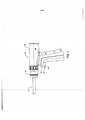
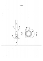
[00020] A Figura 1 é uma vista lateral de uma ferramenta motorizada que incorpora os aspectos desta invenção;[00020] Figure 1 is a side view of a motorized tool that incorporates aspects of this invention;
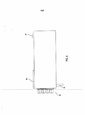
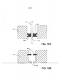
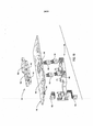
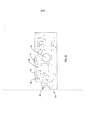
[00021] A Figura 2 é uma vista em seção transversal de uma ferramenta motorizada desta invenção;[00021] Figure 2 is a cross-sectional view of a motorized tool of this invention;
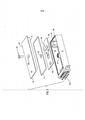
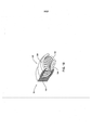
[00022] A Figura 3 é uma vista em perspectiva do módulo de controle vedado com conjunto de vedação;[00022] Figure 3 is a perspective view of the sealed control module with a seal assembly;
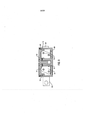
[00023] A Figura 4 é uma vista em planta do topo do módulo de controle com conjunto de vedação;[00023] Figure 4 is a plan view of the top of the control module with a seal assembly;
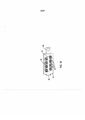
[00024] A Figura 5 é uma vista explodida do módulo de controle que ilustra alguns dos componentes montados ao e no módulo.[00024] Figure 5 is an exploded view of the control module that illustrates some of the components mounted to and on the module.
[00025] A Figura 6 é uma vista em planta do invólucro do módulo de controle sem tampa que ilustra o degrau para o anel-O exterior e o poste para o anel-O interior;[00025] Figure 6 is a plan view of the control module housing without cover, showing the step for the outer O-ring and the post for the inner O-ring;
[00026] A Figura 6A é uma vista em planta do painel inferior do módulo de controle que ilustra os furos que acomodam o conjunto de vedação,[00026] Figure 6A is a plan view of the lower panel of the control module that illustrates the holes that accommodate the seal assembly,
[00027] A Figura 7 é uma vista em planta do fundo da tampa do módulo de controle;[00027] Figure 7 is a top plan view of the bottom of the control module cover;
[00028] A Figura 8 é uma vista em seção transversal ao longo da linha de centro longa do módulo de controle, que ilustra a tampa e invólucro do módulo de controle, fixador, pinos, tampa de retenção exterior, tampa de retenção interior e vedações ativas;[00028] Figure 8 is a cross-sectional view along the long centerline of the control module, which illustrates the control module cover and housing, fastener, pins, outer retaining cap, inner retaining cap and seals active;
[00029] A Figura 9 é uma vista em seção transversal através da linha de centro curta do módulo de controle, que ilustra a tampa do módulo de controle fixada ao invólucro utilizando um fixador;[00029] Figure 9 is a cross-sectional view through the short centerline of the control module, which illustrates the control module cover fixed to the housing using a fastener;
[00030] A Figura 10 é uma vista explodida do conjunto de vedação, que ilustra os pinos, a tampa de retenção exterior, as vedações ativas, e a tampa de retenção interior;[00030] Figure 10 is an exploded view of the seal assembly, which illustrates the pins, the outer retaining cap, the active seals, and the inner retaining cap;
[00031] A Figura 11 é uma vista lateral do pino, que ilustra as seções separadas de diversos diâmetros ao longo da linha de centro longa do eixo do pino e o colar do pino conformado em D;[00031] Figure 11 is a side view of the pin, which illustrates the separate sections of various diameters along the long center line of the pin axis and the D-shaped pin collar;
[00032] A Figura 12 é uma vista em planta da traseira do pino, que ilustra o colar de pino conformado em D;[00032] Figure 12 is a plan view of the rear of the pin, which illustrates the D-shaped pin collar;
[00033] A Figura 13A é uma vista em perspectiva da tampa de retenção exterior;[00033] Figure 13A is a perspective view of the outer retaining cover;
[00034] A Figura 13B é uma vista em planta da face direcionada para fora da tampa de retenção exterior;[00034] Figure 13B is a plan view of the face directed outwards from the outer retaining cover;
[00035] A Figura 13C é uma vista em planta da face direcionada para dentro da tampa de retenção exterior;[00035] Figure 13C is a plan view of the face directed into the outer retaining cover;
[00036] A Figura 14A é uma vista em perspectiva da tampa deretenção interior;[00036] Figure 14A is a perspective view of the inner retaining cover;
[00037] A Figura 14B é uma vista em planta na direção na face direcionada para dentro da tampa de retenção interior;[00037] Figure 14B is a plan view in the direction towards the face directed into the inner retaining cover;
[00038] A Figura 14C é uma vista em planta da face direcionada para fora da tampa de retenção interior;[00038] Figure 14C is a plan view of the face directed outwards from the inner retaining cover;
[00039] A Figura 15 é uma vista em seção transversal do módulo de controle, que ilustra o invólucro de módulo juntamente com o conjunto de vedação acabado inserido dentro do invólucro do módulo, o conjunto de vedação ilustrando cada pino, vedação ativa, tampa de retenção exterior, e tampa de retenção interior;[00039] Figure 15 is a cross-sectional view of the control module, which illustrates the module housing together with the finished seal assembly inserted into the module housing, the seal assembly illustrating each pin, active seal, cover of outer retainer, and inner retainer cover;
[00040] A Figura 16 é uma vista em planta do painel inferior do módulo de controle, que ilustra o conjunto de vedação acabado dentro do invólucro de módulo;[00040] Figure 16 is a plan view of the lower panel of the control module, which illustrates the finished seal assembly inside the module housing;
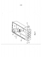
[00041] A Figura 17 é uma vista em perspectiva do invólucro do módulo de controle, que ilustra as duas fileiras de furos escalonados sobre o painel inferior do invólucro, para aceitar um conjunto de vedação ativa;[00041] Figure 17 is a perspective view of the control module housing, which illustrates the two rows of holes staggered over the lower housing panel, to accept an active seal assembly;
[00042] A Figura 18 é uma vista em seção de uma vedação ativa que ilustra uma bota e uma mola colocada dentro da bota;[00042] Figure 18 is a sectional view of an active seal that illustrates a boot and a spring placed inside the boot;
[00043] A Figura 18A é uma vista em seção de uma modalidade alternativa do conjunto de vedação que ilustra um batente integrado com a vedação ativa e uma mola colocada dentro da bota de vedação;[00043] Figure 18A is a sectional view of an alternative embodiment of the seal assembly that illustrates an integrated stop with the active seal and a spring placed inside the seal boot;
[00044] A Figura 18B é uma vista em seção de batentes alternativos que podem ser componentes do conjunto de vedação;[00044] Figure 18B is a sectional view of alternative stops that can be components of the seal assembly;
[00045] A Figura 19 é uma vista explodida de uma modalidade alternativa do módulo de controle, que ilustra alguns dos componentes aí montados e no módulo, incluindo: uma montagem, uma pluralidade de sensores Hall, uma placa de circuito e um espaçador;[00045] Figure 19 is an exploded view of an alternative modality of the control module, which illustrates some of the components mounted there and on the module, including: an assembly, a plurality of Hall sensors, a circuit board and a spacer;
[00046] A Figura 20 é uma vista em perspectiva da montagem;[00046] Figure 20 is a perspective view of the assembly;
[00047] A Figura 21 é uma vista em planta da montagem a partir da frente, topo, fundo e lados;[00047] Figure 21 is a plan view of the assembly from the front, top, bottom and sides;
[00048] A Figura 22 é uma vista em planta do topo do espaçador, e uma vista em perspectiva do espaçador;[00048] Figure 22 is a plan view of the top of the spacer, and a perspective view of the spacer;
[00049] A Figura 23 é uma vista em planta da placa de circuito que ilustra uma pluralidade de furos; e[00049] Figure 23 is a plan view of the circuit board that illustrates a plurality of holes; and
[00050] A Figura 24 é uma vista em planta de uma modalidade alternativa da tampa do módulo de controle, que ilustra uma pluralidade de recessos.[00050] Figure 24 is a plan view of an alternative modality of the control module cover, which illustrates a plurality of recesses.
[00051] As Figuras 1 e 2 ilustram uma ferramenta motorizada 30, uma ferramenta cirúrgica, construída de acordo com esta invenção. A ferramenta 30 tem uma carcaça 32 na qual uma unidade de geração de energia atuada eletricamente é localizada. Na ferramenta específica 30, esta unidade de geração de energia é um motor CC, sem Hall, sem escova 34. A carcaça da ferramenta 32 é conformada para ter uma cabeça genericamente cilíndrica 36, na qual o motor 34 é ajustado. Se estendendo para baixo a partir da cabeça 36, a carcaça da ferramenta 32 é conformada para ter um cabo 38. O cabo 38 é formado para ter um espaço vazio interno 29. Um anexo 31 se estende da carcaça 32 que é conectado à e atuado por meio da unidade de geração de energia 34 para realizar uma tarefa cirúrgica/médica.[00051] Figures 1 and 2 illustrate a motorized tool 30, a surgical tool, constructed in accordance with this invention. Tool 30 has a
[00052] Também contido na cabeça 36 existe um conjunto de acoplamento 39 representado por um anel montado de maneira móvel na parte frontal da carcaça 32. O conjunto de acoplamento 39 consiste da articulação mecânica que liga de maneira liberável um anexo cirúrgico 31 ao motor 34 de modo que o motor pode atuar o anexo 31. Em alguns sistemas de ferramenta desta invenção o anexo é referido como um acessório de corte. A estrutura exata do conjunto de acoplamento 39 não é relevante para a estrutura desta invenção. Se, como na ferramenta das Figuras 1 e 2 a unidade de geração de energia é motor 34, o conjunto de acoplamento 39 consiste de um arranjo de travamento que mantém de maneira liberável o acessório ao eixo motor 27, de modo que o acessório gira ou oscila com a rotação do eixo motor. Em algumas versões da invenção um conjunto engrenagem de redução de velocidade 28 é localizado entre o motor 34 e o conjunto de acoplamento 39.[00052] Also contained in the
[00053] Colocado dentro do espaço vazio do cabo 29 existe um módulo de controle vedado 40. O módulo de controle 40, como discutido abaixo, contém os componentes que regulam a aplicação de corrente de energização ao motor 34. Um circuito que pode ser empregado com esta versão da invenção está descrito nas Patentes US números 5.747.953 e 7.638.958 do Consignatário do Requerente, anteriormente incorporadas para referência.[00053] Placed inside the empty space of
[00054] Energia para energizar o motor 34 é a partir de uma bateria (não identificada). Na prática, a bateria é ligada de maneira removível à extremidade de fundo do cabo 38. Uma bateria que pode ser empregada com esta versão da invenção está descrita no Pedido de Patente Publicado No. 2007/0090788 do Consignatário do Requerente, publicado em 26 de abril de 2007, e aqui incorporado para referência.[00054] Energy to energize the motor 34 is from a battery (not identified). In practice, the battery is removably attached to the bottom end of the
[00055] Também mostrados na Figura 1, existem dois comutadores gatilho 46 e 47 arranjados em tandem se estendendo para frente da face frontal do cabo 38. Cada comutador gatilho 46 e 47 é montado de maneira deslizante na carcaça de ferramenta 32. Cada comutador gatilho 46 e 47 inclui um barril genericamente cilíndrico 50. O barril 50 é a porção do comutador gatilho 46 ou 47 que se estende para frente do cabo da carcaça 38. Cada comutador gatilho 46 e 47 tem uma cabeça (não identificado) conformada como um apoio de dedo e é colocado sobre a extremidade livre distal do barril 50. (“Distal” deve ser entendido significar no sentido do local cirúrgico ao qual a ferramenta 30 é direcionada. “Proximal” significa afastado do local cirúrgico). Comutadores gatilho 46 e 47 são montados à carcaça da ferramenta 32 de modo que os barris 50 são localizados na frente, e são alinhados com o módulo de controle 40.[00055] Also shown in Figure 1, there are two trigger switches 46 and 47 arranged in tandem extending in front of the front face of the
[00056] Como mostrado nas Figuras 2, 3 e 4, uma aba 50 é utilizada para orientar o módulo de controle 40 dentro do cabo 38 da ferramenta 30. A aba 50 se estende de maneira perpendicular para fora do painel lateral 51 do módulo de controle 50. A aba 50 é adjacente ao painel inferior 53. A aba 50 é formada com uma abertura não identificada. A aba 50 serve como um suporte para acomodar um fixador (não ilustrado) utilizado para manter um módulo de controle 40 no cabo 38.[00056] As shown in Figures 2, 3 and 4, a
[00057] Também mostrado na Figura 3, existem pinos 75 que se estendem através do painel inferior do invólucro 53. Os pinos 75 fornecem conexões elétricas para os componentes internos ao invólucro do módulo 58. Um conjunto de vedação 56 é localizado sobre o painel inferior 53 para prender pinos 75 ao invólucro do módulo de controle 58. Adicionalmente, a tampa 60 assenta no topo do invólucro do módulo de controle 58 e é presa ao invólucro 58 utilizando um fixador rosqueado 55. Pinos 75 se estendem perpendicularmente para fora a partir do painel inferior 53 do invólucro do módulo 58. Pinos são presos dentro do conjunto de vedação 56 por meio de um ajuste prensado, enquanto o conjunto de vedação é ajustado em compressão no invólucro do módulo 58. Em uma modalidade preferida da invenção, os pinos 75 são constituídos de ligas eletricamente condutoras tal como níquel e latão folheado a ouro.[00057] Also shown in Figure 3, there are
[00058] A Figura 4 é uma vista em planta do módulo de controle 40. A Figura 2 ilustra como o módulo 40 assenta em um espaço vazio 29 do cabo 38. Pinos 75 se estendem de maneira perpendicular para longe da parte inferior do módulo de controle 40.[00058] Figure 4 is a plan view of
[00059] O módulo de controle 40, agora descrito por meio de referência inicial às Figuras 3-5, inclui uma carcaça que consiste de um invólucro 58 e uma tampa 60. Ambas, o invólucro 58 e a tampa 60, são formadas de alumínio. Em uma modalidade preferida desta invenção o invólucro e a tampa 60 são formadas de liga de alumínio 7075 T6. Esta liga tem uma resistência a escoamento de pelo menos 420 MPa. o invólucro do módulo de controle 58 abriga uma placa de circuito impresso 59. A tampa 60 é fixada ao topo do módulo 50 utilizando um fixador rosqueado 55. Dois anéis-O 61 e 62 são colocados entre o invólucro 58 e a tampa 60. Pinos 75 se estendem através de aberturas 69 (Figura 6A) no invólucro 58.Os pinos 75 fornecem trajetos condutores para/a partir de componentes de controle internos ao módulo 40.Um conjunto de vedação 56 forma um conjunto de vedações individuais ao redor dos pino 75.[00059] The
[00060] O invólucro do módulo de controle 58, melhor vista nas Figuras 5 e 17, tem cinco painéis, um painel inferior 53, um par de painéis laterais 51 e 52, um painel de topo 54 e um painel de base 63. O painel de base 63 é o maior dos painéis, os painéis 51, 54 se estendem perpendicularmente para fora a partir das arestas do painel de base 63. Quando o módulo de controle 40 está assentado no invólucro de módulo 58, o painel lateral 52 é o mais distal dos painéis, e se estende longitudinalmente dentro do cabo 38. Os painéis inferior e de topo 53 e 54, respectivamente, se estendem perpendicularmente para trás através do cabo 38 a partir das arestas opostas de topo e de fundo do painel lateral 52. O painel lateral 51 é o mais próximo dos painéis. O painel lateral 51 se estende entre as extremidades proximais dos painéis inferior e de topo 53 e 54, respectivamente. O painel lateral 42 se estende entre as extremidades distais dos painéis inferior e de topo 53 e 54, respectivamente.[00060] The
[00061] Na versão ilustrada da invenção, os painéis 51 e 52 têm uma espessura comum, a distância entre as faces interior e exterior de aproximadamente 1,4 mm. O painel 54 tem uma espessura de aproximadamente 1,9 mm. O painel inferior 53 tem uma espessura de aproximadamente 6,35 mm. o invólucro 58 é formada de modo que duas fileiras de aberturas 69 se estendem através do painel inferior 53. Cada fileira de aberturas 69 contém quatro aberturas.o invólucro 58 é ainda conformada de modo a ter um degrau 102 dentro dos painéis 51-54 que é recuado em relação ao aro exterior do invólucro. Aqui, o aro exterior é as faces coplanares dos painéis 51-54 (aro não identificado) que são direcionadas no sentido da tampa 60. O degrau 102 se estende de maneira circunferencial ao redor do invólucro 58 e é recuado para dentro em relação ao aro. O degrau 102 é espaçado para dentro para longe da aresta exterior do aro do invólucro. As seções do degrau 102, deveria, portanto ser apreciado, são formadas em cada um dos painéis 51, 54.[00061] In the illustrated version of the invention,
[00062] Um poste 57 é formado de maneira integrada com, e se estende para fora, a partir do painel base do invólucro 63. O poste 57 se estende para longe a partir da face interior do painel base 63 no sentido da tampa 60. O poste 57 é cilíndrico em forma. O poste tem a altura menor do que aquela de painéis 51-54. O poste 57 é formado para ter um furo rosqueado de extremidade fechada 97, com mostrado na Figura 17, que se estende para dentro a partir da face circular exterior do poste (face do furo não identificada). O poste 57 é ainda formado de modo a ter uma ranhura anular 65 como visto na Figura 6 e 17, que se estende para dentro a partir da face do poste. A ranhura 65 é assim localizada para dentro da parede circular exterior do poste 57 e voltada para fora da superfície interior do poste que define o furo 97. Em outra modalidade desta invenção, diversos postes 57 são integrados de maneira formal com, e se estendem para fora a partir do painel base do invólucro 63.[00062] A
[00063] Localizado interno a, e formado de maneira integrada com o invólucro 58, existe um bloco 66. O bloco 66 é localizado dentro do invólucro 58 no canto onde o painel lateral 52 e o painel de topo 54 se encontram. o invólucro 58 é formada de modo que o bloco 66 se estende para fora a partir da face interior do painel de base 63. A altura do bloco 66 é menor do que a altura semelhante dos painéis 51-54. Duas chavetas 67 e 68 se estendem de maneira distal para frente a partir da face exterior do painel lateral do invólucro 52. A chaveta 67 é circular em forma.A chaveta 68 é retangular em forma. Como visto na Figura 6 a chaveta 67 se estende sobre o painel lateral 52 a partir de uma localização espaçada do painel de topo 54. A chaveta 67 se estende essencialmente para fora a partir da face exterior do painel lateral 57, que é diretamente oposta à seção da face interior do painel 52 contra a qual o bloco 66 encontra. o invólucro 58 é ainda formada de modo que um furo rosqueado de extremidade fechada 43, visto em invisível na Figura 17, se estende para dentro a partir da face exposta da chaveta 67 através da seção adjacente do painel lateral 52 e para o interior do bloco 66. A chaveta 68 se estende desde a extremidade do painel lateral 51 que forma uma aresta de canto com o painel de fundo 53. A chaveta 68 se estende ao longo do painel lateral 52 por uma distância igual a aproximadamente um quarto do comprimento total do painel.[00063] Located inside a, and formed in an integrated manner with
[00064] O invólucro do módulo de controle 58 é também formado para ter uma aba 50. A aba 50 se estende para longe da face exterior do painel lateral 51. A aba 50 é localizada imediatamente acima da aresta de fundo do painel 51, acima do painel inferior 53. A aba 50 é formada com uma forma triangular a partir da vista de topo. Na versão ilustrada da invenção, a aba 50 é genericamente na forma de um triângulo retângulo no qual a hipotenusa se estende para cima e para longe para fora afastada do painel de fundo do invólucro 51. A aba 50 é formada de modo que na seção a mais exterior existe uma abertura vazada (não identificado).[00064] The
[00065] Como mostrado nas Figuras 5 e 7, a tampa 60 é formada como uma unidade de peça única e é conformada para ter um painel 106. O painel 106 é na forma de um retângulo com cantos arredondados. O painel 106 é dimensionado para ajustar deslizando no espaço vazio definido pelos painéis do invólucro 51-54. Duas nervuras 73 e 74 são formadas de maneira integrada com o painel 106. As nervuras 73 e 74 se estendem para baixo a partir das arestas longitudinais opostas do painel 106. Cada nervura 73 e 74 se estende de maneira longitudinal ao longo do painel 106. Cada nervura 73 e 74 é localizada para dentro de uma das arestas longitudinais do painel 106. A nervura 73 é ligeiramente mais curta em comprimento que a nervura 74. A diferença em comprimento de nervura e de modo que quando a tampa está assentada sobre o invólucro 58 a extremidade truncada da nervura 73 pode assentar próximo ao bloco de invólucro 66.[00065] As shown in Figures 5 and 7, cover 60 is formed as a single piece unit and is shaped to have a panel 106. Panel 106 is in the form of a rectangle with rounded corners. Panel 106 is sized to fit by sliding into the void defined by the panels of enclosure 51-54. Two
[00066] A tampa 60 é ainda formada para ter um aro 104 que se projeta para fora a partir do painel 106. O aro 104 se estende para fora ao redor do perímetro exterior do painel 106, e se estende de maneira circunferencial ao redor do painel 106. O comprimento adicionado e largura do aro 104 proporcionam à tampa 60 um comprimento e largura iguais às dimensões correspondentes do invólucro 58. A superfície exterior do aro 104 é coplanar com a superfície exterior do painel da tampa 106. A espessura do aro 104 é menor do que aquela do painel 106. Consequentemente, no lado interior da tampa 60 existe um degrau (não identificado) entre a superfície interior do aro 104 e a superfície interior do painel 106.[00066] The
[00067] Uma saliência cilíndrica 70 também se estende para baixo a partir do painel da tampa 106. A saliência 70 é posicionada de modo que quando a tampa 60 é colocada sobre o invólucro 58, a saliência 70 é alinhada com o poste do invólucro subjacente 57. A saliência 70 tem um diâmetro ligeiramente maior do que aquele do poste do invólucro 57. A saliência 70 é formada para ter uma face interior que tem uma tampa 71 que se estende para baixo no sentido do painel de base do invólucro 63. A tampa 61 se estende circunferencialmente ao redor do perímetro exterior da face interior da saliência 70. A tampa 71 que é como anel em forma, tem um diâmetro interior que facilita o ajustamento deslizante apertado da tampa 71 ao redor do poste do invólucro 57. A tampa 60 é ainda formada de modo que um furo 72 se estende axialmente através da saliência 70 e da seção sobrejacente do painel da tampa 106. O painel da tampa 106 tem um contrafuro afunilado 108 que se estende no sentido para dentro e é centralizado ao redor do furo 72.[00067] A cylindrical projection 70 also extends downwardly from the cover panel 106. The projection 70 is positioned so that when the
[00068] Anéis-O 61 e 62 são feitos de borracha/plástico tal como fluoroelastômeros. O material do qual os dois anéis-O 61 e 62 são formados deve ser capaz de suportar exposição a temperaturas de pelo menos 135 °C sem quebrar. Um tal material é um fluoroelastômero fabricado por Seals Eastern, Inc., e vendido sob a marca comercial AFLAS. Ambos os anéis-O 61 e 62 são circulares em seção transversal.[00068] O-
[00069] O anel-O interior 62 é circular em forma, e é dimensionado para ajustar na ranhura 65 formada na face exposta do poste de invólucro 57. O diâmetro exterior do anel-O 62 é tal que ele se estende aproximadamente 0,25 mm acima do poste 57.[00069] The inner O-ring 62 is circular in shape, and is sized to fit in the
[00070] O anel-O exterior 61 é retangular em forma, e é projetado para assentar sobre o degrau do invólucro 102. O anel-O 61 é projetado para se estender acima do aro exterior do invólucro 58 pela mesma distância que o anel-O 62 se estende acima do poste 57.[00070] The outer O-
[00071] As Figuras 8 e 10-14 mostram os componentes do conjunto de vedação 56. Especificamente o conjunto inclui um número de vedações ativas 79. Cada vedação ativa 79 se estende entre um dos pinos e a parede interior circular do painel inferior do invólucro 53 que define a abertura 69 através da qual o pino se estende. Uma tampa de retenção exterior 76 é ajustada prensada nas aberturas 69 do painel inferior 63. A tampa de retenção exterior 76 é pressionada sobre pinos 75. Uma tampa de retenção interior 77, também parte do conjunto de vedação, é ajustada prensada nas aberturas 69 do painel inferior 53. Tampas de retenção 76 e 77 mantém vedações ativas 79 em aberturas 69.Em uma versão desta invenção, vedação ativa 79 é vedação energizada de poliamida.[00071] Figures 8 and 10-14 show the components of the
[00072] As Figuras 11 e 12 ilustram o pino 75 sobre o qual sinais elétricos são conduzidos entre os componentes internos do módulo de controle 40 e os componentes externos. Cada pino 75 tem um colar conformado em D 80, uma cabeça 82 e um eixo 83. O colar 80 se projeta radialmente além da extremidade do eixo 83. A cabeça 82 tem um furo extremo fechado 110. O eixo 83 é constituído de três seções de diâmetro decrescente. Existe uma primeira porção 84, a seção de diâmetro máximo que se estende para dentro a partir do colar 80. Uma segunda porção 85 se estende para dentro a partir da primeira porção 84. Uma terceira porção 86 se estende para dentro a partir da segunda porção 85. A primeira porção 84 tem um diâmetro que é maior do que o diâmetro da segunda porção 85. A segunda porção 85 tem um diâmetro que a maior do que o diâmetro da terceira porção 86.[00072] Figures 11 and 12 illustrate
[00073] Na versão descrita da invenção o módulo 40 tem oito pinos 75.Dois pinos 75 são conectados à fonte de energia da ferramenta. Um pino 75 de cada um é conectado a cada um dos enrolamentos trifásicos internos ao motor da ferramenta 34. Os três pinos remanescentes 75 servem como elementos condutores sobre os quais sinais de controle e estado da ferramenta são trocados entre os componentes dentro do módulo 40 e aqueles fora do módulo. Cada pino 75 se estende através de um separado dos furos de invólucro 69. Em uma modalidade da invenção, pelo menos um pino é utilizado para gerar a conexão elétrica para componentes internos ao invólucro do módulo 58.[00073] In the described version of the invention,
[00074] Está mostrada na Figura 13 a tampa de retenção exterior conformada em paralelogramo 76. A tampa de retenção exterior 76 da Figura 13 tem uma placa de tampa exterior conformada em paralelogramo 91 com cantos arredondados (não identificado). Uma pluralidade de saliências de tampa 92 igual ao número de aberturas de painel inferior do invólucro 69 se estendem para dentro a partir da face direcionada para dentro da placa 91, a face direcionada no sentido do invólucro 58. Saliências 92 têm um diâmetro que facilita o ajuste prensado das saliências 92 nas aberturas do invólucro 69. Um furo 90 se estende axialmente através da saliência 92 e da seção da placa 91 a partir da qual o furo se projeta. O furo 90 tem um diâmetro que é um ajuste prensado em relação ao diâmetro da primeira porção do eixo de pino 84. Abas conformadas de maneira retangular 81 se estendem para fora a partir da face direcionada para fora da placa de tampa exterior 91. Seis abas 81 se estendem para fora a partir da placa exterior 91. Onde duas abas 81 são localizadas de cada lado do furo 92, as abas são espaçadas separadas por uma distância ligeiramente maior do que a distância entre os lados paralelos opostos de um colar de pino 80. Quando o módulo de controle 40 está montado, os colares de pino 80 são localizados adjacentes às abas 81. As abas 81 assim inibem o movimento de rotação dos pinos 75.[00074] Figure 13 shows the outer retaining cap shaped in
[00075] Está mostrada na Figura 14 a tampa de retenção interior conformada em paralelogramo 77. A tampa de retenção interior 77 da Figura 14 tem uma placa de tampa interior conformada em paralelogramo 93 com cantos arredondados (não identificado). Uma pluralidade de saliências de tampa 94 e igual número de aberturas de painel inferior do invólucro 69 se estendem para fora a partir da face direcionada para fora da placa 93, a placa direcionada para invólucro 58. Saliências 94 têm um diâmetro que facilita o ajuste prensado das saliências 94 nas aberturas do invólucro 69. Um furo de tampa interior 95 se estende axialmente através da saliência da tampa 94 e da seção da placa 93 a partir da qual o furo se projeta. O furo 95 tem um diâmetro que é um ajuste prensado em relação ao diâmetro da segunda porção de eixo de pino 85. A terceira seção de eixo de pino 86 é ajustada deslizante através de todo o conjunto de vedação 56.[00075] The
[00076] Cada vedação ativa 79, uma vista na Figura 18, inclui uma bota 120 e uma mola 130. A bota 120 é formada de PTFE vendido sob a marca comercial TEFLON ou outro material que tem, ao mesmo tempo, algum grau de flexibilidade e capacidade de suportar os rigores de esterilização em autoclave. A bota 120 deve também ser capaz de não derreter quando exposta ao calor associado com arames de soldagem para pinos 75. A bota 120 é genericamente como anel em forma. A bota 120 tem uma base 122 que em seção transversal parece conformada de maneira retangular. Duas saias separadas espaçadas, conformadas em anel, 124 e 126, se estendem para longe das seções opostas interior e exterior da base 122. Ambas as saias 124 e 126 se estendem genericamente para longe da face direcionada para fora da base da bota 122. A saia 124, a saia interior, também se estende ligeiramente radialmente para dentro a partir da face anular interior da base 122.A saia 126, a saia exterior, se estende ligeiramente radialmente para fora a partir da face anular exterior da base 122.[00076] Each
[00077] Devido ao espaçamento separado das saias 124 e 126, existe um espaço anular (não identificado) acima da base 122 entre as saias 124 e 126.[00077] Due to the separate spacing of
[00078] A mola 130 é formada de uma liga com base em níquel-cromo, vendida sob a marca comercial INCONEL. Este material como bota 120 é capaz de suportar a esterilização da ferramenta 30. O metal que forma a mola 130 é enrolado de maneira helicoidal. A mola 130 é assentada no espaço anular entre as saias da bota 124 e 126. A mola 130 tem um diâmetro que é maior do que a largura através do espaço entre as saias. Por exemplo, se este espaço tem uma largura relaxada de 1,0 mm, a mola tem um diâmetro de 1,1 mm. Em versões alternativas da invenção, a mola 130 pode ser substituída por um elemento de solicitação que replica a força de deslocamento da mola 130.[00078]
[00079] A mola 130 impõe uma força de deslocamento sobre as saias que fazem com que a saia interior 124 abaúle para dentro no sentido do centro da bota 120, e a saia exterior 126 abaúle para fora, para longe do centro da bota. De maneira coletiva, a bota 120 e a mola 130 são selecionadas de modo que quando a vedação ativa é montada, a distância entre as superfícies exteriores da saia da bota 124 e 126 seja maior do que o espaço anular presente entre a seção do pino 75 colocado no furo do invólucro 69 e a superfície interior adjacente que define furo do invólucro 58. Na versão descrita da invenção, a vedação ativa é colocada ao redor da segunda porção do pino da haste 85. A saia interior 124 pressiona contra esta porção do pino. A saia exterior 126 comprime contra a parede anular circundante do invólucro 58 que define o furo 69. Esta porção do pino tem um diâmetro de aproximadamente 1,530 mm. O furo do invólucro 69 tem um diâmetro de aproximadamente 4,43 mm. À distância através das saias de bota abauladas 124 e 126 é aproximadamente 1,46 mm.[00079] The
[00080] A placa de circuito impresso 59 contém os componentes 140 utilizados para regular a aplicação de energia para a unidade de geração de energia da ferramenta, motor 34. A estrutura exata dos componentes 140 é uma função da unidade de geração de energia integrada com a ferramenta. Portanto, a estrutura destes componentes não é material para esta invenção. Quando a unidade de geração de energia é um motor, o circuito descrito na Patente US número 7.638.958, incorporada para referência, pode ser construído sobre a placa de circuito 59. Estes componentes incluem primeiro e segundo conjuntos de sensores (não ilustrado). O primeiro conjunto de sensores monitora a atuação dos comutadores gatilho 46 e 47. O segundo conjunto de sensores monitora o estado do motor da ferramenta. Para facilitar a capacidade de resposta dos sensores, porções do invólucro 58 podem ser formadas de material através do qual a quantidade física (quantidades) monitorada pelos sensores pode(m) passar. Por exemplo, se um ou mais dos sensores monitora um campo magnético (campos), as seções adjacentes do invólucro podem ser formadas de combinações de material magnético e não magnético que focaliza o campo (campos). Se os sensores monitoram energia fotônica (luz) o invólucro 58 pode ter painéis ou seções de painéis que são transparentes ao comprimento de onda da luz monitorada.[00080] The printed
[00081] A placa de circuito impresso 59 é formada com uma abertura138. Quando a placa de circuito 59 está assentada no invólucro da carcaça 58, o poste do invólucro 57 se estende através da abertura 138.[00081] The printed
[00082] O módulo de controle 40 é primeiro montado por pinos de ajustamento prensado 75 nos furos da tampa 90 da tampa de retenção exterior 76. De maneira mais particular, as primeiras porções da haste do pino 34 são ajustadas prensadas em furos da tampa 90 de modo que as porções remanescentes das hastes do pino se estendem para fora através de saliências 92. Vedações ativas 79 são então inseridas sobre as segundas porções de haste de pino 85. A tampa de retenção exterior 76 é então ajustada prensada ao painel inferior 53 do invólucro 58 de modo que saliências 92 assentam nos furos de invólucro 69. Cada vedação ativa 79 é ajustada no furo de invólucro associado 69 de modo que, como visto na Figura 8, as extremidades livres das saias de bota 124 e 126 são direcionadas no sentido das saliências de tampa de retentor exterior adjacentes 92. Quando cada vedação é assim posicionada, a mola 130 simultaneamente faz com que a saia da bota 124 comprima contra a porção da segunda haste de pino 85 e a saia de bota 126 para comprimir contra a parede circular interior do invólucro 58 que define o furo 69. Cada vedação 79 funciona assim como uma vedação substancialmente estanque a gás entre cada pino 75 e a porção circundante do furo do invólucro e 69.[00082] The
[00083] A tampa de retenção interior 77 é então ajustada sobre a face interior do painel inferior do invólucro 53 e os pinos 75. Devido à dimensão relativa do pino 75 e furos de saliência 95, as saliências de tampa 94 inicialmente são ajustadas deslizantes sobre a terceira seção de eixo de pino 86. Então, as saliências de tampa 94 são simultaneamente ajustadas prensadas nas aberturas de painel inferior 69 e sobre as segundas seções de eixo de pino 85. Os componentes que formam um conjunto de vedação 56 são ainda configurados de modo que quando montados, as vedações ativas 79 não são comprimidas entre as saliências de tampa opostas 92 e 94. Ao invés disto, mesmo com vedações 79 colocadas em um furo 69, existe espaço dentro de cada furo de invólucro 69 para a vedação ativa 79 mover entre as saliências de tampa 92 e 94. Na versão descrita da invenção na qual o furo de invólucro 69 tem um comprimento de 6,35 mm e um diâmetro de 4,43 mm, a distância é aproximadamente 1,91 mm. Quando o conjunto de vedação 56 é montado ao invólucro 58, as terceiras porções de pino 89 se estendem além da placa de tampa interior 93 para o interior do invólucro 58.[00083] The
[00084] Uma vez que o conjunto de vedação 56 é montado ao invólucro 58, a placa de circuito 59 é ajustada no topo do painel de base 63 do invólucro de módulo 58. Na versão descrita da invenção, a placa de circuito 59 é ajustada abaixo das duas fileiras de pinos. Contatos na placa de circuito 59, não ilustrado e não parte desta invenção, estabelecem conexões mecânicas e condutoras entre a fileira de fundo de pinos 75. Pinos 75 criam conexões mecânicas e condutoras entre as porções pino expostas 86 adjacentes ao topo da placa e os componentes na placa. Conexões de solda e arame não ilustradas e não parte desta invenção, podem ser utilizadas para estabelecer trajetos condutores entre os pinos 75 que se estendem sobre a placa de circuito 59 e componentes complementares da placa.[00084] Once the
[00085] Fixadores ou adesivo, não ilustrado e não parte desta invenção, são utilizados para manter a placa de circuito no invólucro 58.[00085] Fasteners or adhesive, not shown and not part of this invention, are used to hold the circuit board in the
[00086] Uma vez que a placa de circuito 59 esteja no lugar, montagem do módulo de controle é completada pela prisão da tampa 60 ao invólucro 58. Este processo começa com o assentamento do anel 61 sobre o degrau de módulo 102. O anel 62 é assentado na ranhura do poste 65. A tampa 60 é então ajustada sobre a extremidade aberta do invólucro 58. Devido ao dimensionamento dos componentes existe um ajuste deslizante próximo entre a superfície exterior de cada nervura de tampa 73 e 74 e a superfície interior de, respectivamente, o painel lateral adjacente 52 e 51. A folga entre cada nervura 73 e 74 e o painel lateral adjacente pode ser aproximadamente 0,05 mm. Como uma consequência do ajustamento da tampa 60 sobre o invólucro, a saliência da tampa 70 assenta sobre o poste de invólucro 57. De maneira mais particular, a tampa 71 integral com a saliência de tampa 70, é ajustada ao redor do perímetro exterior do poste 57.[00086] Once the
[00087] O fixador 55 é então utilizado para prender a tampa 60 aoinvólucro 58. O fixador 55 é também preso à tampa 60 com um adesivo fabricado pela Henkel Company e vendido sob a marca comercial Loctite. O fixador é inserido através do furo da tampa 72 e rosqueado no furo do poste do invólucro 97. Quando apertado o fixador 55 pressiona a tampa 60 contra o invólucro 58. Como resultado deste movimento, o anel-O 61 é comprimido entre o degrau de invólucro 102 e o aro da tampa 104. O anel-O 62 é comprimido entre a ranhura do poste do invólucro 65 e a face da saliência da tampa 70, de modo que a saliência da tampa 70 fornece uma vedação de face. Como consequência da compressão dos anéis-O 61 e 62, os anéis-O formam vedações substancialmente estanques a gás entre o invólucro que forma a carcaça de módulo 58 e a tampa 60.[00087]
[00088] O módulo de controle montado 40 é então inserido no espaço vazio do cabo 29. Chavetas 67 e 68 servem como espaçadores para assegurar que o módulo de controle 40 está posicionado de maneira adequada no cabo 38. A chaveta 68 também serve para transferir calor gerado pelos componentes elétricos internos do módulo de controle 40. Calor dissipado do invólucro 58 se transfere através da chaveta 68 para o interior do cabo 38. Fixadores, não ilustrado, mantém o módulo de controle 40 no cabo 38. Um fixador se estende através de furo rosqueado de extremidade fechada 43 da chaveta 67 para o bloco 66 para o módulo âncora 40 para o cabo 38, para ancorar o módulo 40 ao cabo 38. Um segundo fixador se estende através da abertura na aba 50 para um elemento estrutural adjacente interno ao cabo de ferramenta 38. A aba 50 é angulada para forçar o módulo de controle 40 para o interior do cabo 38. Uma vez que o módulo de controle 40 está preso ao restante da ferramenta 30 os condutores apropriados (não ilustrado) são ligados às cabeças de pino expostas 82. Cada condutor é preso por solda aos furos extremos fechados 110 internos da cabeça de pino 82, como mostrado na Figura 10.[00088] The mounted
[00089] Uma vez que a ferramenta 30 esteja completamente montada, a ferramenta está pronta para utilização. A ferramenta é utilizada como uma ferramenta convencional. O praticante de médico comprime um dos comutadores gatilho 46 ou 47. Este movimento é detectado pelo circuito interno ao módulo 40. O circuito então faz com que os sinais de energização apropriados sejam aplicados ao motor 34. Isto resulta em o acessório de corte ser atuado para realizar o procedimento médico/cirúrgico desejado.[00089] Once tool 30 is completely assembled, the tool is ready for use. The tool is used like a conventional tool. The practitioner compresses one of the trigger switches 46 or 47. This movement is detected by the internal circuit of
[00090] Uma vez que a ferramenta 30 é utilizada, a ferramenta pode ser esterilizada em autoclave como uma ferramenta convencional. Neste processo, a ferramenta é colocada em uma câmara vedada, para o interior da qual vapor saturado é introduzido em temperaturas até 135 °C e pressões tão elevadas quanto 305,000 Pa absoluta. Durante este processo o vapor altamente pressurizado comprime contra o exterior da carcaça do módulo. Um vácuo de 686 mm de mercúrio é então trazido ao cabo. Os anéis-O que formam vedação 61 e 62 impedem essencialmente qualquer vazamento do vapor altamente pressurizado para o interior do módulo de controle 40. Durante o ciclo de pressurização com vapor, o vapor pressurizado comprime para dentro sobre os elementos estruturais da carcaça de módulo, painéis de invólucro 51, 54 e 63 e tampa 60. As pressões diferenciais entre o interior e exterior da carcaça de módulo resultam na flexão para dentro dos painéis da carcaça, especialmente a tampa 60 e o painel de base do invólucro 63. Esta flexão para dentro da tampa 60 é oposta pelo encontro do poste de invólucro 57 contra a tampa. Durante o ciclo de trazer um vácuo a pressão diferencial resulta na flexão para fora dos painéis que formam a carcaça. Esta flexão para fora da tampa 60 é oposta pelas nervuras 73 e 74 e o fixador 55. A inibição desta flexão para fora do invólucro 58 e da tampa 60 reduz o deslocamento da tampa 60 para longe do anel-O exterior 61 e a quebra da vedação estabelecida pelo contato do anel-O contra a tampa.[00090] Once tool 30 is used, the tool can be sterilized in an autoclave like a conventional tool. In this process, the tool is placed in a sealed chamber, into which saturated steam is introduced at temperatures up to 135 ° C and pressures as high as 305,000 Pa absolute. During this process, the highly pressurized steam compresses against the outside of the module housing. A vacuum of 686 mm of mercury is then brought to the cable. O-rings that form seals 61 and 62 essentially prevent any leakage of the highly pressurized steam into the
[00091] Durante esterilização as vedações 79 funcionam como barreiras substancialmente estanques a gás entre o furo 69 que define paredes do painel inferior do invólucro 53 e pinos 75. Deveria ser apreciado que durante o processo de esterilização o invólucro do módulo 58 e os pinos 75 sofrem alguma expansão térmica. Coeficientes de expansão térmica dos materiais que formam o invólucro do módulo 58 e pinos 75 são diferentes. O pino 75 tem um coeficiente térmico de expansão mais baixo do que o invólucro circundante 58. Consequentemente, existe um aumento na largura do espaço anular entre cada pino 75 e a parede do invólucro circundante. Em resposta a esta mudança, cada mola de vedação 130 empurra as saias de bota adjacentes 124 e 126 para fora, para longe uma da outra. Assim, cada vedação 79 mantém a barreira entre o invólucro 58 e o pino associado 75 durante esta porção do processo de autoclave. Também durante esta porção do processo de autoclave, uma fração do vapor pressurizado pode escoar para o interior do espaço anular entre cada par de saias de vedação 124 e 126. Este vapor pressurizado funciona assim como uma segunda força que empurra as saias 124 e 126 para fora, para longe uma da outra, de modo à ainda aprimorar a estanqueidade da vedação substancialmente estanque a gás.[00091] During sterilization the
[00092] Mesmo com esta deformação da bota 120, a saia 124 ainda encontra o pino 75 e a saia 126 ainda encontra a parede interior circundante do painel inferior do invólucro 53. Cada vedação 79 mantém, portanto, uma barreira ao redor do pino 75 sobre o qual a vedação está assentada. Além disto, esta deformação da vedação também significa que a expansão térmica do invólucro 58 e pino 75 não é oposta por quaisquer forças que poderiam impor tensões de indução de fratura sobre estes componentes.[00092] Even with this deformation of the
[00093] Durante este processo, o empurrar para fora das saias de vedação 124 e 126 para longe uma da outra, provoca um alongamento das saias. As saias são capazes de expandir para o interior do espaço de folga no furo 69 entre saliências de tampa 92 e 94. Esta capacidade das saias 124 e 126 de expandir livremente permite às botas 120 manterem sua integridade.[00093] During this process, pushing out of the sealing
[00094] Uma vez que a ferramenta 30 está esterilizada, a ferramenta é removida da autoclave.A temperatura da ferramenta retorna para níveis ambientes.Neste momento o invólucro 58 e pinos 75 sofrem contração térmica. Em resposta à diminuição em tamanho destes componentes, a largura do espaço anular entre cada pino 75 e a parede do invólucro circundante diminui. Isto provoca como uma diminuição na distância entre as saias de bota 124 e 126. Cada mola 130 é, portanto, submetida alguma compressão radial. Devido à sua natureza flexível, as molas 130 são capazes de sofrer esta compressão sem deformar de maneira plástica mecanicamente. Consequentemente, cada mola 130 é ainda capaz de impor força sobre a bota associada que mantém as saias 124 e 126 afastadas uma da outra. Molas 130 são assim capazes de suprir as forças necessárias para manter vedações ao redor de pinos 75 uma vez que a ferramenta é, com o tempo, submetida a diversas esterilizações em autoclave.[00094] Once the tool 30 is sterilized, the tool is removed from the autoclave. The temperature of the tool returns to ambient levels. At this point the
[00095] A ferramenta 30 desta invenção tem um módulo de controle com ajustes de vedações capazes de suportar os rigores de repetidas esterilizações em autoclave. Anéis-O 61 e 62 impedem vapor de penetrar entre o módulo 40 entre o invólucro 58 e a tampa 60. Devido ao mesmo material utilizado para formar o invólucro 58 e a tampa 60, criando coeficientes iguais de expansão térmica, anéis-O são capazes de serem utilizados. O conjunto de vedação 56 bloqueia vapor quanto a penetrar no módulo de controle 40 através de furos do invólucro 69. Ambos estes conjuntos de vedações são relativamente econômicos para fornecer.[00095] Tool 30 of this invention has a control module with sealing adjustments capable of withstanding the rigors of repeated autoclaving sterilizations. O-
[00096] Além disto, o invólucro 58 e a tampa 60 têm aspectos postes de invólucro 57 e nervuras de tampa 73 e 74 que inibem a flexão da carcaça do módulo de controle quando a ferramenta 30 é pressurizada duranteesterilização. Aumentando a rigidez da tampa 60 o risco de ter a vedação quebrada é reduzido.[00096] In addition,
[00097] Outro benefício da ferramenta 30 desta invenção sobre uma ferramenta com um módulo de controle caldeado ou soldado fechado, é que é possível abrir facilmente o módulo 40. Isto é realizado desatarraxando o fixador 55 e então removendo a tampa 60. Assim poder-se-ia remover periodicamente a tampa 60 do invólucro 58. Este processo pode ser realizado em um ambiente de trabalho muito seco (baixa umidade) para facilitar a evaporação de qualquer água que possa ter-se introduzido para o interior da carcaça do módulo. Os componentes internos ao módulo podem ser inspecionados para determinar se existe qualquer evidência de corrosão potencialmente indutora de falha. Antes de prender novamente a tampa 60 ao invólucro 58, a carcaça pode ser dotada de novos anéis-O 61 e 62. Assim, diferentemente de alguns módulos de controle atuais, o módulo de controle desta invenção é projetado para permitir a manutenção preventiva e reparo.Isto pode evitar o processo mais caro de ter que dotar periodicamente a ferramenta com um módulo de controle completamente novo.[00097] Another benefit of tool 30 of this invention over a tool with a closed welded or brazed control module, is that it is possible to easily
[00098] A descrição acima é direcionada para uma versão da invenção.Outras versões da invenção podem ter aspectos diferentes daquela que foi descrita.[00098] The above description is directed to a version of the invention. Other versions of the invention may have different aspects than the one described.
[00099] Por exemplo, não há requisito que todas as versões da invenção contenham ao mesmo tempo o conjunto de vedação descrito 56 e anéis-O 61 e 62.Outras versões desta invenção podem ter apenas um único dos aspectos.[00099] For example, there is no requirement that all versions of the invention contain the described
[000100] Em algumas versões da invenção os anéis-O 61 e/ou 62 podem ser substituídos por uma vedação ativa similar à vedação ativa 79. Cada vedação ativa deveria ter uma bota dimensionada para ajustar entre onde a cobertura e a tampa deveriam, de outra maneira, se encontrar. Interno à bota existe um, ou mais componentes de deslocamento similares à mola de vedação 130 que exerce uma força sobre as saias da bota.Estas vedações ativas deveriam ser similares em forma e tamanho aos anéis-O 61 e 62. Estas vedações ativas deveriam fornecer a função da vedação ativa 79 na localização de anéis-O 61 e 62 atuais. Em outras versões da invenção anéis-O 61 e/ou 62 podem ser substituídos por uma gaxeta ou um material capaz de maneira similar de estabelecer uma vedação substancialmente estanque a gás entre os elementos estruturais do módulo de controle. A função de vedação realizada por ambos os anéis-O 61 e 62 pode ser realizada por uma única peça de um material elastomérico. Esta peça de material elastomérico é posicionada de modo a se estender entre ambas as interfaces do invólucro aro para tampa e a interface poste para tampa.[000100] In some versions of the invention the O-
[000101] Nestas, bem como em outras modalidades da invenção, pode não ser necessário fornecer o invólucro do módulo com um degrau direcionado para dentro, contra o qual assenta a vedação de aro para tampa. Assim, nestas versões da invenção a vedação aro para tampa pode encontrar diretamente a face a mais exterior do aro do invólucro.[000101] In these, as well as in other embodiments of the invention, it may not be necessary to provide the module housing with a step directed inwards, against which the rim seal for the lid rests. Thus, in these versions of the invention the rim-to-cover seal can directly meet the outermost face of the enclosure rim.
[000102] Em versões alternativas da invenção, componentes diferentes das saliências da tampa podem servir como os batentes que impedem movimento longitudinal das vedações ativas para fora do painel do módulo no qual elas estão assentadas. Não há requisito que uma pluralidade de saliências de tampa, para a tampa de retenção interior, ou a tampa de retenção exterior, se estendam a partir de uma placa comum. Nestas versões da invenção, associadas com cada vedação ativa, existe um batente interior e um batente exterior. Nenhum destes batentes é conectado a qualquer um dos outros batentes que podem ser ajustados ao painel de módulo comum. Isto é especialmente verdadeiro em versões da invenção nas quais os pinos condutores que se estendem através do módulo de controle são amplamente espaçados separados um do outro (0,5 cm mais) ou se estendem através depainéis diferentes no módulo de controle.[000102] In alternative versions of the invention, components other than the protrusions of the cover can serve as the stops that prevent longitudinal movement of the active seals out of the module panel on which they are seated. There is no requirement that a plurality of lid protrusions, for the inner retaining cap, or the outer retaining cap, extend from a common plate. In these versions of the invention, associated with each active seal, there is an inner and an outer stop. None of these stops is connected to any of the other stops that can be adjusted to the common module panel. This is especially true in versions of the invention in which the conductor pins extending through the control module are widely spaced apart from each other (0.5 cm more) or extend through different panels in the control module.
[000103] Além disto, esta invenção não está limitada a conjuntos de vedação onde os batentes são elementos cilíndricos rígidos que são simplesmente pressionados para o interior da abertura do painel no qual eles são assentados. Um tal batente alternativo 125, agora descrito por meio de referência à Figura 18A. O primeiro batente 125 e a vedação ativa 127 são uma única peça de borracha. O batente 125 pode ser formado de maneira integrada como uma porção da vedação ativa 127, de modo a se ajustar de maneira apertada contra o furo que define a parede interior do painel inferior 53. O primeiro batente 125 é um degrau circunferencial, ou anel, localizado para dentro a partir da parede interior que define furo do painel inferior 53. O batente 125 e vedação 127 são colocados ao redor de um pino condutor 75. Uma mola 130 é colocada entre as saias de bota de vedação (não identificado). Não ilustrado na Figura 18A existe um segundo batente.[000103] Furthermore, this invention is not limited to seal assemblies where the stops are rigid cylindrical elements that are simply pressed into the opening of the panel in which they are seated. Such an
[000104] Em versões alternativas da invenção, um primeiro batente 128 pode ser formado integralmente com o painel com o próprio painel 53 como mostrado na Figura 18B. O batente 128 é constituído do mesmo material que o painel 53. Nestas versões da invenção o batente 128 consiste de um anel circunferencial ou degrau que é parte do painel que se estende para dentro para o interior do furo que define a parede interior do painel inferior 53, no qual o pino condutor 75 e a vedação ativa 79 estão assentados. Este anel ou degrau pode estar em nível com qualquer das paredes exterior ou interior do painel inferior 53, e atua como qualquer de um batente interior ou exterior. Alternativamente este anel ou degrau pode ser recuado em relação à parede interior ou exterior do painel inferior 53. Existe, não ilustrada na Figura 18B, a vedação ativa 79 ou pino condutor 75.[000104] In alternative versions of the invention, a
[000105] Em algumas versões da invenção, um anel de compressão 129 como mostrado na Figura 18B, pode funcionar como um, se não ambos, os batentes interior ou exterior. Nestas versões da invenção, um anel de compressão 129 forma a função batente (ou tampão). Pode ser necessário fornecer um painel 53 com uma ranhura anular (não identificado) que se estende para fora a partir do furo que define a parede interior do painel inferior 53. O perímetro exterior ou superfície do anel de compressão 129, assenta ou encaixa na ranhura anular.[000105] In some versions of the invention, a
[000106] Estes diversos aspectos alternativos podem também ser combinados. Por exemplo, o anel de compressão ou batente pode ser formado de maneira integrada com a vedação ativa quando da montagem do módulo. O perímetro exterior da porção anel de compressão é ajustado em encaixe na ranhura formada no furo que define a parede interior do painel inferior 53.[000106] These various alternative aspects can also be combined. For example, the compression ring or stop can be formed in an integrated manner with the active seal when assembling the module. The outer perimeter of the compression ring portion is fitted into the groove formed in the hole that defines the inner wall of the
[000107] Da mesma maneira, em algumas versões da invenção, os aspectos que inibem rotação dos pinos condutores podem ser formados com os batentes interiores.[000107] Likewise, in some versions of the invention, aspects that inhibit rotation of the conducting pins can be formed with the interior stops.
[000108] De maneira similar, esta invenção não está limitada a ferramentas cirúrgicas motorizadas com bateria. Em outras versões da invenção, a ferramenta que recebe energia sobre e um cabo conectado a um console de controle. Em outras versões da invenção, a unidade de geração de energia pode ser um dispositivo que gera energia elétrica, energia térmica ou energia fotônica. Outras ferramentas podem gerar outras formas de energia mecânica, tais como ferramentas projetadas para vibrar o acessório de corte anexado.[000108] Similarly, this invention is not limited to battery powered surgical tools. In other versions of the invention, the tool that receives power over and a cable connected to a control console. In other versions of the invention, the power generation unit can be a device that generates electrical energy, thermal energy or photonic energy. Other tools can generate other forms of mechanical energy, such as tools designed to vibrate the attached cutting attachment.
[000109] Em outras versões da invenção, a ferramenta pode não ter o poste de encontro do invólucro. Ainda outras versões da invenção podem ter diversos postes de encontro do invólucro. Nestas versões da invenção menos do que todos os postes podem ser dotados de aspectos para facilitar a prisão da tampa sobrejacente ao poste.[000109] In other versions of the invention, the tool may not have the post against the housing. Still other versions of the invention may have several posts against the housing. In these versions of the invention less than all the posts can be provided with features to facilitate the attachment of the cover overlying the post.
[000110] De maneira similar, não há requisito que em todas as versões da invenção a tampa seja dotada com as duas nervuras de enrijecimento descritas. Em algumas versões da invenção a tampa pode ter apenas uma única nervura de enrijecimento. Da mesma maneira, em algumas versões da invenção, pode ser desejável fornecer a tampa com três ou mais nervuras de enrijecimento. De maneira similar, não é requisito que em todas as versões da invenção as nervuras sejam simples estruturas lineares.Outras versões da invenção podem ter nervuras com formas não lineares.[000110] Similarly, there is no requirement that in all versions of the invention the cover be provided with the two stiffening ribs described. In some versions of the invention the cover may have only a single stiffening rib. Likewise, in some versions of the invention, it may be desirable to provide the cover with three or more stiffening ribs. Similarly, it is not a requirement that in all versions of the invention the ribs are simple linear structures. Other versions of the invention may have ribs with non-linear shapes.
[000111] Da mesma maneira, o conjunto de vedação 56 pode ter outras construções diferentes daquela que foi descrita. Como mencionado acima, o número real de vedações ativas é uma função do número de pinos requeridos para fornecer trajetos condutores para/a partir do módulo de controle. Se não houver necessidade de fornecer o módulo com pinos para estabelecer enlaces de comunicações externas, menos pinos e vedações companheiras são necessários. Uma ferramenta com sensores localizados fora do módulo de controle pode requerer mais pinos e, portanto, mais vedações. Quando uma vedação de pino desta invenção é fornecida não é requisito que um único retentor interior ou exterior mantenha todas as vedações ativas 79 no lugar. Em algumas versões da invenção um par de retentores companheiros interior e exterior podem manter uma única vedação ativa 79 em posição.[000111] In the same way, the
[000112] Da mesma maneira, em algumas versões da invenção, a construção da ferramenta pode necessitar que os pinos que se estendem para o interior da carcaça do módulo sejam agrupados juntos.Em algumas versões da invenção, um conjunto de pinos pode se estender através de um primeiro dos painéis de carcaça, enquanto um segundo conjunto de pinos se estende através de um painel de carcaça separado.Assim, nesta e em outras versões da invenção, uma ferramenta desta invenção pode ter diversos conjuntos de vedação espaçados separados 56, cada um dos quais inclui uma ou mais vedações ativas.[000112] Likewise, in some versions of the invention, the construction of the tool may require that the pins extending into the module housing be grouped together. In some versions of the invention, a set of pins may extend across of a first of the housing panels, while a second set of pins extends through a separate housing panel. Thus, in this and other versions of the invention, a tool of this invention may have several separate spaced
[000113] A menos que descrito nas reivindicações, as dimensões descritas são para finalidades de ilustração apenas.[000113] Unless described in the claims, the dimensions described are for purposes of illustration only.
[000114] Da mesma maneira, embora o módulo desta invenção seja projetado para utilização com uma ferramenta cirúrgica, sua utilização não está limitada a este tipo de ferramenta. O módulo pode ser utilizado para vedar componentes contidos em outros dispositivos. Por exemplo, o módulo pode ser utilizado para vedar componentes utilizados em ambientes marinhos ou do espaço aéreo. Além disto, o módulo pode não ser apenas utilizado para abrigar componentes utilizados para regular a operação de uma ferramenta. Em aplicações alternativas, o módulo desta invenção pode ser utilizado para abrigar componentes utilizados para realizar funções diferentes daquelas que controlam uma unidade de geração de energia.Por exemplo, em uma aplicação marinha, o módulo desta invenção pode ser utilizado para abrigar componentes utilizados para processar sinais transmitidos/recebidos a partir de um transdutor de sonar. Assim, é o objetivo das reivindicações anexas cobrirem todas tais variações e modificações que vêm dentro do verdadeiro espírito e escopo desta invenção.[000114] Likewise, although the module of this invention is designed for use with a surgical tool, its use is not limited to this type of tool. The module can be used to seal components contained in other devices. For example, the module can be used to seal components used in marine or airspace environments. In addition, the module may not only be used to house components used to regulate the operation of a tool. In alternative applications, the module of this invention can be used to house components used to perform functions different from those that control a power generation unit. For example, in a marine application, the module of this invention can be used to house components used to process signals transmitted / received from a sonar transducer. Thus, it is the aim of the appended claims to cover all such variations and modifications that come within the true spirit and scope of this invention.
[000115] Da mesma maneira, o módulo de controle vedado 40 desta invenção pode também ser projetado para facilitar a montagem do módulo 40 e seus componentes internos. Nesta versão da invenção, vista na Figura 19, um espaçador 144 é ligado sobre uma superfície de um painel de controle 142, uma placa de circuito impresso. Uma montagem 160 mantém uma pluralidade de sensores Hall 162, 164, 166 e 168 para a placa de circuito impresso 142 dentro do módulo 40. A montagem 160, juntamente com o espaçador 144 alinham componentes internos em todos os três eixos durante e depois de fabricação.[000115] In the same way, the sealed
[000116] Nesta versão do módulo 40 uma placa de circuito impresso 142 contém uma pluralidade de sensores analógicos Hall 162, 164 e 166 utilizados para regular a aplicação de energia à unidade de geração de energia da ferramenta, motor 34, ou para serem atuados por comutadores gatilho 46, 47 agora descritos por meio de referência às Figuras 1, 2 e 19. Um sensor 168 é um sensor Hall digital.A posição de sensores Hall analógicos 162, 164 é uma função da localização da unidade de geração de energia integrada com a ferramenta. Quando a unidade de geração de energia é um motor, o circuito descrito na Patente US número 7.638.958, incorporada para referência, pode ser construído sobre a placa de circuito 142.[000116] In this version of module 40 a printed
[000117] Cada sensor analógico é constituído de um corpo, não identificado, e uma pluralidade de condutores elétricos, não identificado, que se estendem para longe do corpo. Sensores analógicos 162 e 164 facilitam regulação da aplicação da energia para o rotor do motor 34. O sensor 164 tem condutores elétricos mais longos do que o sensor 162 por razões de fabricação. Cada par sensor analógico 166 e sensor Hall digital 168 é utilizado para regular a aplicação de energia ao motor proporcional à posição de um comutador gatilho de ferramenta associado 46 ou 47. A Patente US número 7.638.958 do Consignatário do Requerente, aqui incorporada para referência, divulga um sensor Hall analógico/sensor Hall digital para energizar o motor 34 ou gatilhos 46, 47.[000117] Each analog sensor consists of a body, unidentified, and a plurality of electrical conductors, unidentified, that extend away from the body.
[000118] A montagem 160 é constituída de uma única peça de plástico. A montagem 160 é constituída de três seções: uma base 170, uma seção conformada em L 172, e uma seção conformada em H 174, agora descrita por meio de referência às Figuras 20 e 21. A base 170 tem extremidades opostas, não identificado. Sobre cada extremidade da base 170 existe um par de paredes laterais espaçadas separadas 171 que definem um par de fendas 176. Uma seção de conexão 173 conecta cada parede lateral 171 com cada parede lateral oposta 171. Paredes laterais 171 se estendem acima da altura da base 170. Paredes laterais 171 são aproximadamente iguais em altura.Cada fenda 176 é localizada para a frente da seção de conexão 173. Na superfície de topo da base 170 existe um pedestal 188. O pedestal 188 é retangular em forma e se estende desde a superfície da base 170. O pedestal 188 é localizado na traseira da base 170 e espaçado igualmente entre extremidades opostas da base 170. Se estendendo desde uma superfície de topo do pedestal 188 existe um poste 186. O poste 186 é circular em forma e tem um diâmetro aproximado de 1,4 mm. Conectada adjacente à base 170 está a seção conformada em L 172. A seção conformada em L 172 se estende para longe de uma extremidade da base 170. A seção conformada em L 172 é ligada à base 170 de modo a ser alinhada com a seção de conexão adjacente 173. Localizado em uma extremidade da seção conformada em L 172 existe um pedestal 184. O pedestal 184 é retangular em forma e se estende desde uma superfície de topo da seção conformada em L 172. O pedestal 184 é aproximadamente igual em dimensão transversal ao pedestal 188. Se estendendo para longe a partir de uma superfície de topo do pedestal 184 existe um poste 182. O poste 182 é circular em forma, e tem um diâmetro igual ao diâmetro do poste 186. Localizado na extremidade oposta da seção conformada em L172 existe um pedestal 180. O pedestal 180 é conformado em C e se estende desde a superfície de topo da porção conformada em L 172. O pedestal 180 é menor em dimensão transversal do que os pedestais 184 e 188. Se estendendo para longe de uma superfície de topo do pedestal 180 existe um poste 178. O poste 178 é menor em diâmetro do que os postes 182 e 186. Conectada adjacente ao pedestal 180 de seção conformada em L 172 existe a seção conformada em H 174. A seção conformada em H 174 tem um par de paredes paralelas opostas espaçadas separadas 175. As paredes 175 compreendem as extremidades opostas da seção conformada em H 174.Conectando as paredes 175 existe uma viga transversal 177. A viga 177 é aproximadamente linear com seção conformada em L 172 e base 170. Paredes 175 com a viga 177 definem um par de fendas 176. Cada fenda 176 é dimensionada para assentar o corpo de um sensor analógico 162, 164 e 166 ou o corpo de um sensor Hall digital 168, como mostrado pela Figura 19.[000118]
[000119] Pedestais 180, 184 e 188 se estendem até a mesma altura acima da base 170 de modo a formar um plano para encontrar contra uma superfície de fundo da placa de circuito 142. Postes 178, 182 e 186 também se estendem até a mesma altura acima da base 170, de modo a formar um plano.[000119]
[000120] Um espaçador 144, agora descrito por meio de referência à Figura 22, é constituído de uma única peça de plástico. O espaçador tem aproximadamente 1,4 mm de espessura. O espaçador 144 tem um par de furos vazados 146 e 148. Os furos vazados do espaçador 146 e 148 são ligeiramente maiores em diâmetro para montar postes 182 e 186, respectivamente. O espaçador 144 ainda inclui um furo circular 150 e um furo conformado em L 152. O furo 150 tem aproximadamente o mesmo diâmetro que uma abertura 158 da placa de circuito impresso 142 (e abertura 138 da placa de circuito impresso 59) como mostrado nas Figuras 22 e 23. O furo 152 fornece espaço para componentes tal como um capacitor, não identificado, ligado à superfície de topo da placa de circuito impresso 142. A localização exata do furo 152 não é definida e é uma função de componentes externos na placa de circuito impresso 142, que requerem espaço durante a montagem final.[000120] A
[000121] A placa de circuito impresso 142 é agora ainda descrita por referência à Figura 23. Em algumas versões desta invenção a placa de circuito impresso 142 do módulo de controle 40 pode ser substituída por placa de circuito impresso divulgada anteriormente 59, como mostrado na Figura 5. Em algumas versões desta invenção, ambas as placas de circuito impresso 142 e a placa de circuito impresso 59 estão presentes.Se estendendo desde uma aresta de topo da placa de circuito 142 existem penínsulas 155 e 157.Cada península contém três furos igualmente espaçados separados, não identificados, para acomodar os condutores elétricos de um sensor Hall 168.Os três condutores elétricos de cada sensor 168 são ajustadas deslizantes através dos três furos de península.Sensores são ligados à placa de circuito 142 com montagem 160.Condutores de sensor são soldados à placa.A placa de circuito impresso 142 é ainda formada com uma abertura 158.A placa de circuito 142 ainda inclui furos 149 154 a 156. O furo 149 é localizado em uma aresta lateral da placa de circuito impresso 142. O furo 149 é ligeiramente maior em diâmetro do que o poste de montagem 178. Furos 154 e 156 são ligeiramente maiores em diâmetro do que os postes de montagem 186 e 182, respectivamente. Cada furo de placa de circuito é ligeiramente maior do que seu respectivo poste, para fornecer um espaço. Este espaço é criado por razões de fabricação, de modo que um adesivo pode ligar a placa de circuito sobre os postes de montagem. A montagem 160 é presa à placa de circuito impresso 142 utilizando o arranjo poste no furo visto na Figura 19.[000121] Printed
[000122] Mostrada na Figura 24 existe uma tampa 179. A tampa 179 é uma modalidade alternativa de tampa anteriormente descrita 60 desta invenção. A tampa 179 é formada com todos os aspectos da tampa 60.[000122] Shown in Figure 24 is a
[000123] Uma superfície de fundo da tampa 179 inclui uma pluralidade de recessos de extremidade fechada 181. A forma e profundidade de cada recesso 181 é uma função do tipo de componente localizado na superfície de topo da placa de circuito impresso 142. Cada recesso 181 é dimensionado para fornecer espaço para um componente de placa de circuito associado, por razões de fabricação. Furos recuados 183 e 185 são ainda formados sobre a tampa 179 e são de extremidade fechada. Cada furo 183 é dimensionado para receber o poste de montagem 178 dentro da superfície de fundo da tampa 179. Furos 185 são dimensionados para receber postes de montagem 182 e 186 dentro da superfície de fundo da tampa 179. Recortes 187 são recessos dentro de nervura previamente descrita 73 desta invenção.Recortes 187 são cortados da nervura 73 para permitir espaço para cada península de placa de circuito associada 155 e 157. Durante a montagem final, penínsulas de placa de circuito 155 e 157 assentam dentro de recortes da tampa 187.[000123] A bottom surface of the
[000124] A montagem 160 é equipada com sensores 162, 164 e 166 colocando a montagem 160 em um gabarito. Uma vez que a montagem 160 está assentada no gabarito, sensores 162 e 166 são assentados dentro das fendas de montagem associadas 176 como mostrado na Figura 19. O sensor 162 é assentado dentro da fenda superior 176 da seção conformada em H 174.Sensores digitais 168 são então assentados dentro de fendas de montagens associadas 176.Sensores são inseridos à mão ou por meio de pinças. Os condutores elétricos de cada sensor são pré-dobrados e cortados de modo que eles ajustam deslizantes na placa de circuito 142. Os condutores elétricos de sensores Hall analógicos de rotor de motor 162 e 164 são mais longos por razões de fabricação e embalagem.[000124]
[000125] Um adesivo é em seguida aplicado ao redor das aberturas da placa de circuito impresso 142 onde postes de montagem 178, 182, 186 são ajustados deslizantes através.O sensor Hall analógico 164 é assentado dentro da fenda de montagem 176 da seção conformada em H 174.A placa de circuito impresso 142 é ajustada sobre a montagem 160. Neste processo a placa 142 é ajustada sobre os condutores de sensor de modo que os condutores de sensor assentam nas aberturas correspondentes na placa. Os condutores de sensor são soldados à placa.Soldagem liga as superfícies exteriores de condutores elétricos à placa de circuito 142. Simultaneamente, o poste de montagem 178 é ajustado deslizante através do furo da placa de circuito 149 e postes de montagem 182 e 186 são ajustados deslizantes através de furos da placa de circuito 154 e 156, respectivamente. Adesivo industrial é aplicado ao redor da superfície exterior de cada poste para prender a montagem 160 ao espaçador 144.Devido ao espaço entre cada poste e furo de placa associado, adesivo penetra no espaço entre uma superfície exterior de cada poste e uma parede interior de cada furo de placa para criar uma ligação mais forte. Uma vez que três pontos definem um plano, os postes de montagem orientam os sensores Hall para a tampa 179 e então o módulo de controle 40. Postes de montagem auxiliam em controlar os componentes “X” e “Y” em relação ao posicionamento de cada sensor e a montagem dentro do conjunto global. O espaçador 144 controla o componente ”Z” em relação ao posicionamento de cada sensor e a montagem no conjunto global.[000125] An adhesive is then applied around the openings of the printed
[000126] Adesivo é então aplicado em pontos selecionados ao longo da superfície de topo da placa de circuito 142 e o espaçador 144 é fixado ao topo da placa de circuito 142. Simultaneamente os postes 182 e 186 são ajustados deslizando através de furos espaçadores 146 e 148, respectivamente. Furos 146 e 148 auxiliam na orientação adequada do espaçador em relação à placa de circuito 142 e componentes internos adicionais do módulo de controle 40.[000126] Adhesive is then applied to selected points along the top surface of
[000127] Adesivo é então aplicado ao longo da superfície de topo do espaçador 144. Adesivo é também aplicado à face de topo de cada poste 178, 182 e 186. Montagem é agora presa dentro da superfície de fundo da tampa 179. O espaçador 144 está agora ligado à tampa do módulo de controle 179. A superfície de topo do espaçador 144 encontra a superfície de fundo da tampa 179. A superfície de topo do poste 178 se aproxima, porém não encontra, a superfície de fundo da tampa na localização do recesso circular 183. As superfícies de topo de postes 182 e 186 se aproximam porém não encontram a superfície de fundo da tampa 179 na localização de recessos circulares 185.[000127] Adhesive is then applied along the top surface of the
[000128] Quando o espaçador 144 está assentado na superfície de fundo da tampa 179, a placa de circuito, montagem e sensores, juntamente como um subconjunto, são agora presos à tampa 179. A tampa 179 com o subconjunto que inclui espaçador, placa de circuito, montagem de sensores, é então ligada sobre uma abertura de topo do invólucro do módulo 58. Além disto, o poste do invólucro 57 se estende através da abertura 158 e abertura do espaçador 150.[000128] When
[000129] Consequentemente, sensores Hall analógicos 162, 164 e 166 e sensores Hall digitais 168 são, em virtude da montagem 160, ligados e orientados de maneira adequada para a tampa do módulo de controle 179, orientados de maneira adequada dentro do módulo de controle 40. Como resultado, sensores Hall 162 e 164 são posicionados no sentido do rotor do motor 34. Cada par de sensores Hall 166 e 168 são posicionados no sentido dos comutadores gatilho da ferramenta cirúrgica 46, 47.[000129] Consequently,
[000130] Outro benefício da montagem 160 é para facilidade de calibração depois da montagem final da ferramenta.Quando a ferramenta cirúrgica motorizada desta invenção alcança seu ponto final de montagem, o cabo é calibrado para precisão.Como parte deste processo a saída de sinais pelos sensores é avaliada para determinar se eles estão dentro de certos parâmetros de desempenho predeterminados.A montagem 160 prende cada sensor da placa de circuito 142 de modo que os sensores podem cair espacialmente dentro da zona mecânica requerida para calibração com sucesso. A montagem 160 desta invenção impede que cada sensor montado seja deslocado durante e depois de todos os estágios de montagem, portanto a ferramenta de energia cirúrgica é capaz de sofrer calibração com maior eficácia e facilidade. Utilizando uma montagem para reter sensores em posições pré-determinadas dentro do módulo de controle, a taxa de descarte de fabricação é minimizada devido a menos vibrações com falha. Outro benefício da montagem 160 é que ela permite um processo de montagem barato durante a fabricação. A montagem 160 também fornece uma montagem espacialmente repetitiva e confiável de componentes internos.[000130] Another benefit of
[000131] Em algumas versões desta invenção qualquer um dos postes de montagem 178, 182 ou 186 pode se estender a partir de qualquer superfície interior do módulo de controle 40. Não é necessário que cada poste se estenda desde a montagem 160.Em uma versão desta invenção, pelo menos um poste se estende desde a montagem 160.[000131] In some versions of this invention any of the mounting
[000132] Deveria também ser apreciado que métodos alternativos de montar um módulo de controle estão dentro do escopo desta invenção. Por exemplo, em algumas versões da invenção a montagem com ou sem os sensores já ajustados à montagem é equipado de maneira segura ao módulo de controle antes que os sensores sejam ligados à placa de circuito.[000132] It should also be appreciated that alternative methods of assembling a control module are within the scope of this invention. For example, in some versions of the invention the mounting with or without the sensors already fitted to the mounting is securely fitted to the control module before the sensors are connected to the circuit board.
[000133] Da mesma maneira, não há requisito que a montagem sempre seja presa à tampa do módulo de controle. Em versões alternativas da invenção, a montagem pode ser presa à superfície interior de outro painel que define o espaço vazio do módulo de controle.[000133] In the same way, there is no requirement that the assembly always be attached to the control module cover. In alternative versions of the invention, the assembly can be attached to the interior surface of another panel that defines the empty space of the control module.
[000134] Consequentemente, é um objetivo das reivindicações a seguir, cobrir todas tais modificações e variações que vêm dentro do verdadeiro espírito e escopo desta invenção.[000134] Consequently, it is an objective of the following claims to cover all such modifications and variations that come within the true spirit and scope of this invention.
Claims (20)
Applications Claiming Priority (3)
| Application Number | Priority Date | Filing Date | Title |
|---|---|---|---|
| US201061425523P | 2010-12-21 | 2010-12-21 | |
| US61/425,523 | 2010-12-21 | ||
| PCT/US2011/066226 WO2012088141A2 (en) | 2010-12-21 | 2011-12-20 | Powered surgical tool with a control module in a sealed housing the housing having active seals for protecting internal components from the effects of sterilization |
Publications (2)
| Publication Number | Publication Date |
|---|---|
| BR112013015782A2 BR112013015782A2 (en) | 2018-06-19 |
| BR112013015782B1 true BR112013015782B1 (en) | 2020-12-15 |
Family
ID=45478577
Family Applications (1)
| Application Number | Title | Priority Date | Filing Date |
|---|---|---|---|
| BR112013015782-8A BR112013015782B1 (en) | 2010-12-21 | 2011-12-20 | MOTORIZED SURGICAL TOOL |
Country Status (9)
| Country | Link |
|---|---|
| US (4) | US9295476B2 (en) |
| EP (2) | EP3329866B1 (en) |
| JP (2) | JP6047498B2 (en) |
| KR (1) | KR101885396B1 (en) |
| CN (3) | CN111110314A (en) |
| AU (2) | AU2011349264B2 (en) |
| BR (1) | BR112013015782B1 (en) |
| CA (1) | CA2822623C (en) |
| WO (1) | WO2012088141A2 (en) |
Families Citing this family (243)
| Publication number | Priority date | Publication date | Assignee | Title |
|---|---|---|---|---|
| US11229472B2 (en) | 2001-06-12 | 2022-01-25 | Cilag Gmbh International | Modular battery powered handheld surgical instrument with multiple magnetic position sensors |
| US9060770B2 (en) | 2003-05-20 | 2015-06-23 | Ethicon Endo-Surgery, Inc. | Robotically-driven surgical instrument with E-beam driver |
| US20070084897A1 (en) | 2003-05-20 | 2007-04-19 | Shelton Frederick E Iv | Articulating surgical stapling instrument incorporating a two-piece e-beam firing mechanism |
| US11896225B2 (en) | 2004-07-28 | 2024-02-13 | Cilag Gmbh International | Staple cartridge comprising a pan |
| US10159482B2 (en) | 2005-08-31 | 2018-12-25 | Ethicon Llc | Fastener cartridge assembly comprising a fixed anvil and different staple heights |
| US7669746B2 (en) | 2005-08-31 | 2010-03-02 | Ethicon Endo-Surgery, Inc. | Staple cartridges for forming staples having differing formed staple heights |
| US11246590B2 (en) | 2005-08-31 | 2022-02-15 | Cilag Gmbh International | Staple cartridge including staple drivers having different unfired heights |
| US20070106317A1 (en) | 2005-11-09 | 2007-05-10 | Shelton Frederick E Iv | Hydraulically and electrically actuated articulation joints for surgical instruments |
| US20120292367A1 (en) | 2006-01-31 | 2012-11-22 | Ethicon Endo-Surgery, Inc. | Robotically-controlled end effector |
| US20110290856A1 (en) | 2006-01-31 | 2011-12-01 | Ethicon Endo-Surgery, Inc. | Robotically-controlled surgical instrument with force-feedback capabilities |
| US11793518B2 (en) | 2006-01-31 | 2023-10-24 | Cilag Gmbh International | Powered surgical instruments with firing system lockout arrangements |
| US8820603B2 (en) | 2006-01-31 | 2014-09-02 | Ethicon Endo-Surgery, Inc. | Accessing data stored in a memory of a surgical instrument |
| US8186555B2 (en) | 2006-01-31 | 2012-05-29 | Ethicon Endo-Surgery, Inc. | Motor-driven surgical cutting and fastening instrument with mechanical closure system |
| US7845537B2 (en) | 2006-01-31 | 2010-12-07 | Ethicon Endo-Surgery, Inc. | Surgical instrument having recording capabilities |
| US8708213B2 (en) | 2006-01-31 | 2014-04-29 | Ethicon Endo-Surgery, Inc. | Surgical instrument having a feedback system |
| US10568652B2 (en) | 2006-09-29 | 2020-02-25 | Ethicon Llc | Surgical staples having attached drivers of different heights and stapling instruments for deploying the same |
| US11980366B2 (en) | 2006-10-03 | 2024-05-14 | Cilag Gmbh International | Surgical instrument |
| US8684253B2 (en) | 2007-01-10 | 2014-04-01 | Ethicon Endo-Surgery, Inc. | Surgical instrument with wireless communication between a control unit of a robotic system and remote sensor |
| US7434717B2 (en) | 2007-01-11 | 2008-10-14 | Ethicon Endo-Surgery, Inc. | Apparatus for closing a curved anvil of a surgical stapling device |
| US11672531B2 (en) | 2007-06-04 | 2023-06-13 | Cilag Gmbh International | Rotary drive systems for surgical instruments |
| US8931682B2 (en) | 2007-06-04 | 2015-01-13 | Ethicon Endo-Surgery, Inc. | Robotically-controlled shaft based rotary drive systems for surgical instruments |
| US11849941B2 (en) | 2007-06-29 | 2023-12-26 | Cilag Gmbh International | Staple cartridge having staple cavities extending at a transverse angle relative to a longitudinal cartridge axis |
| US8636736B2 (en) | 2008-02-14 | 2014-01-28 | Ethicon Endo-Surgery, Inc. | Motorized surgical cutting and fastening instrument |
| JP5410110B2 (en) | 2008-02-14 | 2014-02-05 | エシコン・エンド−サージェリィ・インコーポレイテッド | Surgical cutting / fixing instrument with RF electrode |
| US11986183B2 (en) | 2008-02-14 | 2024-05-21 | Cilag Gmbh International | Surgical cutting and fastening instrument comprising a plurality of sensors to measure an electrical parameter |
| US9089360B2 (en) | 2008-08-06 | 2015-07-28 | Ethicon Endo-Surgery, Inc. | Devices and techniques for cutting and coagulating tissue |
| US8210411B2 (en) | 2008-09-23 | 2012-07-03 | Ethicon Endo-Surgery, Inc. | Motor-driven surgical cutting instrument |
| US9386983B2 (en) | 2008-09-23 | 2016-07-12 | Ethicon Endo-Surgery, Llc | Robotically-controlled motorized surgical instrument |
| US11648005B2 (en) | 2008-09-23 | 2023-05-16 | Cilag Gmbh International | Robotically-controlled motorized surgical instrument with an end effector |
| US9005230B2 (en) | 2008-09-23 | 2015-04-14 | Ethicon Endo-Surgery, Inc. | Motorized surgical instrument |
| US8608045B2 (en) | 2008-10-10 | 2013-12-17 | Ethicon Endo-Sugery, Inc. | Powered surgical cutting and stapling apparatus with manually retractable firing system |
| US8663220B2 (en) | 2009-07-15 | 2014-03-04 | Ethicon Endo-Surgery, Inc. | Ultrasonic surgical instruments |
| US11090104B2 (en) | 2009-10-09 | 2021-08-17 | Cilag Gmbh International | Surgical generator for ultrasonic and electrosurgical devices |
| US8469981B2 (en) | 2010-02-11 | 2013-06-25 | Ethicon Endo-Surgery, Inc. | Rotatable cutting implement arrangements for ultrasonic surgical instruments |
| US10945731B2 (en) | 2010-09-30 | 2021-03-16 | Ethicon Llc | Tissue thickness compensator comprising controlled release and expansion |
| US9629814B2 (en) | 2010-09-30 | 2017-04-25 | Ethicon Endo-Surgery, Llc | Tissue thickness compensator configured to redistribute compressive forces |
| US11849952B2 (en) | 2010-09-30 | 2023-12-26 | Cilag Gmbh International | Staple cartridge comprising staples positioned within a compressible portion thereof |
| US11812965B2 (en) | 2010-09-30 | 2023-11-14 | Cilag Gmbh International | Layer of material for a surgical end effector |
| US9386988B2 (en) | 2010-09-30 | 2016-07-12 | Ethicon End-Surgery, LLC | Retainer assembly including a tissue thickness compensator |
| US8978954B2 (en) | 2010-09-30 | 2015-03-17 | Ethicon Endo-Surgery, Inc. | Staple cartridge comprising an adjustable distal portion |
| US10405854B2 (en) | 2010-09-30 | 2019-09-10 | Ethicon Llc | Surgical stapling cartridge with layer retention features |
| KR101885396B1 (en) | 2010-12-21 | 2018-08-03 | 스트리커 코포레이션 | Powered surgical tool with a control module in a sealed housing the housing having active seals for protecting internal components from the effects of sterilization |
| RU2606493C2 (en) | 2011-04-29 | 2017-01-10 | Этикон Эндо-Серджери, Инк. | Staple cartridge, containing staples, located inside its compressible part |
| US9072535B2 (en) | 2011-05-27 | 2015-07-07 | Ethicon Endo-Surgery, Inc. | Surgical stapling instruments with rotatable staple deployment arrangements |
| US8876932B2 (en) * | 2011-08-04 | 2014-11-04 | Makita Corporation | Power tool dust collecting device and power tool |
| JP5729873B2 (en) * | 2011-08-05 | 2015-06-03 | 株式会社マキタ | Dust collector |
| CN109044416A (en) | 2011-12-16 | 2018-12-21 | 史赛克公司 | System for extracting tissue samples from fluid streams generated during medical/surgical procedures |
| MX358135B (en) | 2012-03-28 | 2018-08-06 | Ethicon Endo Surgery Inc | Tissue thickness compensator comprising a plurality of layers. |
| BR112014024098B1 (en) | 2012-03-28 | 2021-05-25 | Ethicon Endo-Surgery, Inc. | staple cartridge |
| US9439668B2 (en) | 2012-04-09 | 2016-09-13 | Ethicon Endo-Surgery, Llc | Switch arrangements for ultrasonic surgical instruments |
| US9101358B2 (en) | 2012-06-15 | 2015-08-11 | Ethicon Endo-Surgery, Inc. | Articulatable surgical instrument comprising a firing drive |
| US20140001231A1 (en) | 2012-06-28 | 2014-01-02 | Ethicon Endo-Surgery, Inc. | Firing system lockout arrangements for surgical instruments |
| US9649111B2 (en) | 2012-06-28 | 2017-05-16 | Ethicon Endo-Surgery, Llc | Replaceable clip cartridge for a clip applier |
| US20140001234A1 (en) | 2012-06-28 | 2014-01-02 | Ethicon Endo-Surgery, Inc. | Coupling arrangements for attaching surgical end effectors to drive systems therefor |
| US9289256B2 (en) | 2012-06-28 | 2016-03-22 | Ethicon Endo-Surgery, Llc | Surgical end effectors having angled tissue-contacting surfaces |
| US20140005705A1 (en) | 2012-06-29 | 2014-01-02 | Ethicon Endo-Surgery, Inc. | Surgical instruments with articulating shafts |
| US9198714B2 (en) | 2012-06-29 | 2015-12-01 | Ethicon Endo-Surgery, Inc. | Haptic feedback devices for surgical robot |
| US9326788B2 (en) | 2012-06-29 | 2016-05-03 | Ethicon Endo-Surgery, Llc | Lockout mechanism for use with robotic electrosurgical device |
| US9351754B2 (en) | 2012-06-29 | 2016-05-31 | Ethicon Endo-Surgery, Llc | Ultrasonic surgical instruments with distally positioned jaw assemblies |
| US9408622B2 (en) | 2012-06-29 | 2016-08-09 | Ethicon Endo-Surgery, Llc | Surgical instruments with articulating shafts |
| US9226767B2 (en) | 2012-06-29 | 2016-01-05 | Ethicon Endo-Surgery, Inc. | Closed feedback control for electrosurgical device |
| US9393037B2 (en) | 2012-06-29 | 2016-07-19 | Ethicon Endo-Surgery, Llc | Surgical instruments with articulating shafts |
| US9700310B2 (en) | 2013-08-23 | 2017-07-11 | Ethicon Llc | Firing member retraction devices for powered surgical instruments |
| US9095367B2 (en) | 2012-10-22 | 2015-08-04 | Ethicon Endo-Surgery, Inc. | Flexible harmonic waveguides/blades for surgical instruments |
| US20140135804A1 (en) | 2012-11-15 | 2014-05-15 | Ethicon Endo-Surgery, Inc. | Ultrasonic and electrosurgical devices |
| MX368026B (en) | 2013-03-01 | 2019-09-12 | Ethicon Endo Surgery Inc | Articulatable surgical instruments with conductive pathways for signal communication. |
| BR112015026109B1 (en) | 2013-04-16 | 2022-02-22 | Ethicon Endo-Surgery, Inc | surgical instrument |
| GB2521228A (en) | 2013-12-16 | 2015-06-17 | Ethicon Endo Surgery Inc | Medical device |
| US9795436B2 (en) | 2014-01-07 | 2017-10-24 | Ethicon Llc | Harvesting energy from a surgical generator |
| US9554854B2 (en) | 2014-03-18 | 2017-01-31 | Ethicon Endo-Surgery, Llc | Detecting short circuits in electrosurgical medical devices |
| US10028761B2 (en) * | 2014-03-26 | 2018-07-24 | Ethicon Llc | Feedback algorithms for manual bailout systems for surgical instruments |
| US10092310B2 (en) | 2014-03-27 | 2018-10-09 | Ethicon Llc | Electrosurgical devices |
| US9737355B2 (en) | 2014-03-31 | 2017-08-22 | Ethicon Llc | Controlling impedance rise in electrosurgical medical devices |
| US9913680B2 (en) | 2014-04-15 | 2018-03-13 | Ethicon Llc | Software algorithms for electrosurgical instruments |
| BR112016023807B1 (en) | 2014-04-16 | 2022-07-12 | Ethicon Endo-Surgery, Llc | CARTRIDGE SET OF FASTENERS FOR USE WITH A SURGICAL INSTRUMENT |
| CN106456176B (en) | 2014-04-16 | 2019-06-28 | 伊西康内外科有限责任公司 | Fastener cartridge including the extension with various configuration |
| US20150297222A1 (en) | 2014-04-16 | 2015-10-22 | Ethicon Endo-Surgery, Inc. | Fastener cartridges including extensions having different configurations |
| CN106456158B (en) | 2014-04-16 | 2019-02-05 | 伊西康内外科有限责任公司 | Fastener cartridge including non-uniform fastener |
| US10285724B2 (en) | 2014-07-31 | 2019-05-14 | Ethicon Llc | Actuation mechanisms and load adjustment assemblies for surgical instruments |
| BR112017004361B1 (en) | 2014-09-05 | 2023-04-11 | Ethicon Llc | ELECTRONIC SYSTEM FOR A SURGICAL INSTRUMENT |
| US20160066913A1 (en) | 2014-09-05 | 2016-03-10 | Ethicon Endo-Surgery, Inc. | Local display of tissue parameter stabilization |
| DE102014218528A1 (en) | 2014-09-16 | 2016-03-17 | Continental Automotive Gmbh | Housing for receiving electrical and / or electronic components, electronic control unit and method for producing the same |
| US9924944B2 (en) | 2014-10-16 | 2018-03-27 | Ethicon Llc | Staple cartridge comprising an adjunct material |
| US11141153B2 (en) | 2014-10-29 | 2021-10-12 | Cilag Gmbh International | Staple cartridges comprising driver arrangements |
| US10517594B2 (en) | 2014-10-29 | 2019-12-31 | Ethicon Llc | Cartridge assemblies for surgical staplers |
| EA036313B1 (en) | 2014-10-30 | 2020-10-26 | Страйкер Фар Ист, Инк. | Surgical tool with an aseptic power module that enters a specific operating state based on the type of handpiece to which the module is attached |
| US9987000B2 (en) | 2014-12-18 | 2018-06-05 | Ethicon Llc | Surgical instrument assembly comprising a flexible articulation system |
| US10004501B2 (en) | 2014-12-18 | 2018-06-26 | Ethicon Llc | Surgical instruments with improved closure arrangements |
| RU2703684C2 (en) | 2014-12-18 | 2019-10-21 | ЭТИКОН ЭНДО-СЕРДЖЕРИ, ЭлЭлСи | Surgical instrument with anvil which is selectively movable relative to staple cartridge around discrete fixed axis |
| US10085748B2 (en) | 2014-12-18 | 2018-10-02 | Ethicon Llc | Locking arrangements for detachable shaft assemblies with articulatable surgical end effectors |
| US10245095B2 (en) | 2015-02-06 | 2019-04-02 | Ethicon Llc | Electrosurgical instrument with rotation and articulation mechanisms |
| US11154301B2 (en) | 2015-02-27 | 2021-10-26 | Cilag Gmbh International | Modular stapling assembly |
| JP2020121162A (en) | 2015-03-06 | 2020-08-13 | エシコン エルエルシーEthicon LLC | Time dependent evaluation of sensor data to determine stability element, creep element and viscoelastic element of measurement |
| US10441279B2 (en) | 2015-03-06 | 2019-10-15 | Ethicon Llc | Multiple level thresholds to modify operation of powered surgical instruments |
| US10390825B2 (en) | 2015-03-31 | 2019-08-27 | Ethicon Llc | Surgical instrument with progressive rotary drive systems |
| US10034704B2 (en) | 2015-06-30 | 2018-07-31 | Ethicon Llc | Surgical instrument with user adaptable algorithms |
| US10765470B2 (en) | 2015-06-30 | 2020-09-08 | Ethicon Llc | Surgical system with user adaptable techniques employing simultaneous energy modalities based on tissue parameters |
| US11051873B2 (en) | 2015-06-30 | 2021-07-06 | Cilag Gmbh International | Surgical system with user adaptable techniques employing multiple energy modalities based on tissue parameters |
| US10898256B2 (en) | 2015-06-30 | 2021-01-26 | Ethicon Llc | Surgical system with user adaptable techniques based on tissue impedance |
| US11129669B2 (en) | 2015-06-30 | 2021-09-28 | Cilag Gmbh International | Surgical system with user adaptable techniques based on tissue type |
| US10105139B2 (en) | 2015-09-23 | 2018-10-23 | Ethicon Llc | Surgical stapler having downstream current-based motor control |
| US11890015B2 (en) | 2015-09-30 | 2024-02-06 | Cilag Gmbh International | Compressible adjunct with crossing spacer fibers |
| US10285699B2 (en) | 2015-09-30 | 2019-05-14 | Ethicon Llc | Compressible adjunct |
| US11058475B2 (en) | 2015-09-30 | 2021-07-13 | Cilag Gmbh International | Method and apparatus for selecting operations of a surgical instrument based on user intention |
| US10595930B2 (en) | 2015-10-16 | 2020-03-24 | Ethicon Llc | Electrode wiping surgical device |
| US10292704B2 (en) | 2015-12-30 | 2019-05-21 | Ethicon Llc | Mechanisms for compensating for battery pack failure in powered surgical instruments |
| US11229471B2 (en) | 2016-01-15 | 2022-01-25 | Cilag Gmbh International | Modular battery powered handheld surgical instrument with selective application of energy based on tissue characterization |
| US11129670B2 (en) * | 2016-01-15 | 2021-09-28 | Cilag Gmbh International | Modular battery powered handheld surgical instrument with selective application of energy based on button displacement, intensity, or local tissue characterization |
| US10709469B2 (en) | 2016-01-15 | 2020-07-14 | Ethicon Llc | Modular battery powered handheld surgical instrument with energy conservation techniques |
| US11213293B2 (en) | 2016-02-09 | 2022-01-04 | Cilag Gmbh International | Articulatable surgical instruments with single articulation link arrangements |
| US10448948B2 (en) | 2016-02-12 | 2019-10-22 | Ethicon Llc | Mechanisms for compensating for drivetrain failure in powered surgical instruments |
| US10555769B2 (en) | 2016-02-22 | 2020-02-11 | Ethicon Llc | Flexible circuits for electrosurgical instrument |
| US10828028B2 (en) | 2016-04-15 | 2020-11-10 | Ethicon Llc | Surgical instrument with multiple program responses during a firing motion |
| US10357247B2 (en) | 2016-04-15 | 2019-07-23 | Ethicon Llc | Surgical instrument with multiple program responses during a firing motion |
| US20170296173A1 (en) | 2016-04-18 | 2017-10-19 | Ethicon Endo-Surgery, Llc | Method for operating a surgical instrument |
| US10426469B2 (en) | 2016-04-18 | 2019-10-01 | Ethicon Llc | Surgical instrument comprising a primary firing lockout and a secondary firing lockout |
| US10456193B2 (en) | 2016-05-03 | 2019-10-29 | Ethicon Llc | Medical device with a bilateral jaw configuration for nerve stimulation |
| US10376305B2 (en) | 2016-08-05 | 2019-08-13 | Ethicon Llc | Methods and systems for advanced harmonic energy |
| US11266430B2 (en) | 2016-11-29 | 2022-03-08 | Cilag Gmbh International | End effector control and calibration |
| WO2018100941A1 (en) * | 2016-11-30 | 2018-06-07 | 日立工機株式会社 | Reciprocating tool |
| US9833256B1 (en) * | 2016-12-14 | 2017-12-05 | Ethicon Endo-Surgery, Llc | Ultrasonic surgical instrument with transducer slip joint |
| US20180168625A1 (en) | 2016-12-21 | 2018-06-21 | Ethicon Endo-Surgery, Llc | Surgical stapling instruments with smart staple cartridges |
| US10537325B2 (en) | 2016-12-21 | 2020-01-21 | Ethicon Llc | Staple forming pocket arrangement to accommodate different types of staples |
| US20180168615A1 (en) | 2016-12-21 | 2018-06-21 | Ethicon Endo-Surgery, Llc | Method of deforming staples from two different types of staple cartridges with the same surgical stapling instrument |
| JP7010956B2 (en) | 2016-12-21 | 2022-01-26 | エシコン エルエルシー | How to staple tissue |
| US20180168575A1 (en) | 2016-12-21 | 2018-06-21 | Ethicon Endo-Surgery, Llc | Surgical stapling systems |
| US10307170B2 (en) | 2017-06-20 | 2019-06-04 | Ethicon Llc | Method for closed loop control of motor velocity of a surgical stapling and cutting instrument |
| US10881399B2 (en) | 2017-06-20 | 2021-01-05 | Ethicon Llc | Techniques for adaptive control of motor velocity of a surgical stapling and cutting instrument |
| US11653914B2 (en) | 2017-06-20 | 2023-05-23 | Cilag Gmbh International | Systems and methods for controlling motor velocity of a surgical stapling and cutting instrument according to articulation angle of end effector |
| US10779820B2 (en) | 2017-06-20 | 2020-09-22 | Ethicon Llc | Systems and methods for controlling motor speed according to user input for a surgical instrument |
| US10993716B2 (en) | 2017-06-27 | 2021-05-04 | Ethicon Llc | Surgical anvil arrangements |
| EP4070740A1 (en) | 2017-06-28 | 2022-10-12 | Cilag GmbH International | Surgical instrument comprising selectively actuatable rotatable couplers |
| US11564686B2 (en) | 2017-06-28 | 2023-01-31 | Cilag Gmbh International | Surgical shaft assemblies with flexible interfaces |
| USD906355S1 (en) | 2017-06-28 | 2020-12-29 | Ethicon Llc | Display screen or portion thereof with a graphical user interface for a surgical instrument |
| US10765427B2 (en) | 2017-06-28 | 2020-09-08 | Ethicon Llc | Method for articulating a surgical instrument |
| US11484310B2 (en) | 2017-06-28 | 2022-11-01 | Cilag Gmbh International | Surgical instrument comprising a shaft including a closure tube profile |
| US10932772B2 (en) | 2017-06-29 | 2021-03-02 | Ethicon Llc | Methods for closed loop velocity control for robotic surgical instrument |
| US11974742B2 (en) | 2017-08-03 | 2024-05-07 | Cilag Gmbh International | Surgical system comprising an articulation bailout |
| US11944300B2 (en) | 2017-08-03 | 2024-04-02 | Cilag Gmbh International | Method for operating a surgical system bailout |
| KR20200043426A (en) | 2017-08-17 | 2020-04-27 | 스트리커 코포레이션 | Portable surgical instruments and methods for providing tactile feedback to users during kickback |
| US10842490B2 (en) | 2017-10-31 | 2020-11-24 | Ethicon Llc | Cartridge body design with force reduction based on firing completion |
| DE102017127723A1 (en) | 2017-11-23 | 2019-05-23 | Schott Ag | Autoclavable medical device and actuator for an autoclavable medical device |
| US10779826B2 (en) | 2017-12-15 | 2020-09-22 | Ethicon Llc | Methods of operating surgical end effectors |
| US20190192151A1 (en) | 2017-12-21 | 2019-06-27 | Ethicon Llc | Surgical instrument having a display comprising image layers |
| US11207065B2 (en) | 2018-08-20 | 2021-12-28 | Cilag Gmbh International | Method for fabricating surgical stapler anvils |
| US11696761B2 (en) | 2019-03-25 | 2023-07-11 | Cilag Gmbh International | Firing drive arrangements for surgical systems |
| US11903581B2 (en) | 2019-04-30 | 2024-02-20 | Cilag Gmbh International | Methods for stapling tissue using a surgical instrument |
| US11660163B2 (en) | 2019-06-28 | 2023-05-30 | Cilag Gmbh International | Surgical system with RFID tags for updating motor assembly parameters |
| US11771419B2 (en) | 2019-06-28 | 2023-10-03 | Cilag Gmbh International | Packaging for a replaceable component of a surgical stapling system |
| US11684434B2 (en) | 2019-06-28 | 2023-06-27 | Cilag Gmbh International | Surgical RFID assemblies for instrument operational setting control |
| US11627959B2 (en) | 2019-06-28 | 2023-04-18 | Cilag Gmbh International | Surgical instruments including manual and powered system lockouts |
| US11350938B2 (en) | 2019-06-28 | 2022-06-07 | Cilag Gmbh International | Surgical instrument comprising an aligned rfid sensor |
| US11638587B2 (en) | 2019-06-28 | 2023-05-02 | Cilag Gmbh International | RFID identification systems for surgical instruments |
| US11553971B2 (en) | 2019-06-28 | 2023-01-17 | Cilag Gmbh International | Surgical RFID assemblies for display and communication |
| CN110678016A (en) * | 2019-08-29 | 2020-01-10 | 中国电子科技集团公司第三十八研究所 | Big cavity structure of spiro union stress decomposition combination laser seal welding |
| CA3155848A1 (en) | 2019-09-26 | 2021-04-01 | Stryker Corporation | Surgical navigation systems and methods |
| US11576672B2 (en) | 2019-12-19 | 2023-02-14 | Cilag Gmbh International | Surgical instrument comprising a closure system including a closure member and an opening member driven by a drive screw |
| US11529137B2 (en) | 2019-12-19 | 2022-12-20 | Cilag Gmbh International | Staple cartridge comprising driver retention members |
| US11911032B2 (en) | 2019-12-19 | 2024-02-27 | Cilag Gmbh International | Staple cartridge comprising a seating cam |
| US11844520B2 (en) | 2019-12-19 | 2023-12-19 | Cilag Gmbh International | Staple cartridge comprising driver retention members |
| US11701111B2 (en) | 2019-12-19 | 2023-07-18 | Cilag Gmbh International | Method for operating a surgical stapling instrument |
| US11559304B2 (en) | 2019-12-19 | 2023-01-24 | Cilag Gmbh International | Surgical instrument comprising a rapid closure mechanism |
| US11950797B2 (en) | 2019-12-30 | 2024-04-09 | Cilag Gmbh International | Deflectable electrode with higher distal bias relative to proximal bias |
| US11937863B2 (en) | 2019-12-30 | 2024-03-26 | Cilag Gmbh International | Deflectable electrode with variable compression bias along the length of the deflectable electrode |
| US11812957B2 (en) | 2019-12-30 | 2023-11-14 | Cilag Gmbh International | Surgical instrument comprising a signal interference resolution system |
| US11452525B2 (en) | 2019-12-30 | 2022-09-27 | Cilag Gmbh International | Surgical instrument comprising an adjustment system |
| US11937866B2 (en) | 2019-12-30 | 2024-03-26 | Cilag Gmbh International | Method for an electrosurgical procedure |
| US11911063B2 (en) | 2019-12-30 | 2024-02-27 | Cilag Gmbh International | Techniques for detecting ultrasonic blade to electrode contact and reducing power to ultrasonic blade |
| US11660089B2 (en) | 2019-12-30 | 2023-05-30 | Cilag Gmbh International | Surgical instrument comprising a sensing system |
| US11779387B2 (en) | 2019-12-30 | 2023-10-10 | Cilag Gmbh International | Clamp arm jaw to minimize tissue sticking and improve tissue control |
| US11786291B2 (en) | 2019-12-30 | 2023-10-17 | Cilag Gmbh International | Deflectable support of RF energy electrode with respect to opposing ultrasonic blade |
| US11696776B2 (en) | 2019-12-30 | 2023-07-11 | Cilag Gmbh International | Articulatable surgical instrument |
| US20210196359A1 (en) | 2019-12-30 | 2021-07-01 | Ethicon Llc | Electrosurgical instruments with electrodes having energy focusing features |
| US20210196357A1 (en) | 2019-12-30 | 2021-07-01 | Ethicon Llc | Electrosurgical instrument with asynchronous energizing electrodes |
| US11986201B2 (en) | 2019-12-30 | 2024-05-21 | Cilag Gmbh International | Method for operating a surgical instrument |
| US11944366B2 (en) | 2019-12-30 | 2024-04-02 | Cilag Gmbh International | Asymmetric segmented ultrasonic support pad for cooperative engagement with a movable RF electrode |
| US11759251B2 (en) | 2019-12-30 | 2023-09-19 | Cilag Gmbh International | Control program adaptation based on device status and user input |
| US11684412B2 (en) | 2019-12-30 | 2023-06-27 | Cilag Gmbh International | Surgical instrument with rotatable and articulatable surgical end effector |
| US11779329B2 (en) | 2019-12-30 | 2023-10-10 | Cilag Gmbh International | Surgical instrument comprising a flex circuit including a sensor system |
| USD975851S1 (en) | 2020-06-02 | 2023-01-17 | Cilag Gmbh International | Staple cartridge |
| USD975850S1 (en) | 2020-06-02 | 2023-01-17 | Cilag Gmbh International | Staple cartridge |
| USD976401S1 (en) | 2020-06-02 | 2023-01-24 | Cilag Gmbh International | Staple cartridge |
| USD974560S1 (en) | 2020-06-02 | 2023-01-03 | Cilag Gmbh International | Staple cartridge |
| US11678904B2 (en) | 2020-07-15 | 2023-06-20 | Ezisurg Medical Co., Ltd. | Control end of surgical instrument and surgical instrument having the control end |
| US20220031346A1 (en) | 2020-07-28 | 2022-02-03 | Cilag Gmbh International | Articulatable surgical instruments with articulation joints comprising flexible exoskeleton arrangements |
| US11617577B2 (en) | 2020-10-29 | 2023-04-04 | Cilag Gmbh International | Surgical instrument comprising a sensor configured to sense whether an articulation drive of the surgical instrument is actuatable |
| US11931025B2 (en) | 2020-10-29 | 2024-03-19 | Cilag Gmbh International | Surgical instrument comprising a releasable closure drive lock |
| US11896217B2 (en) | 2020-10-29 | 2024-02-13 | Cilag Gmbh International | Surgical instrument comprising an articulation lock |
| US11844518B2 (en) | 2020-10-29 | 2023-12-19 | Cilag Gmbh International | Method for operating a surgical instrument |
| USD1013170S1 (en) | 2020-10-29 | 2024-01-30 | Cilag Gmbh International | Surgical instrument assembly |
| US11717289B2 (en) | 2020-10-29 | 2023-08-08 | Cilag Gmbh International | Surgical instrument comprising an indicator which indicates that an articulation drive is actuatable |
| US11779330B2 (en) | 2020-10-29 | 2023-10-10 | Cilag Gmbh International | Surgical instrument comprising a jaw alignment system |
| USD980425S1 (en) | 2020-10-29 | 2023-03-07 | Cilag Gmbh International | Surgical instrument assembly |
| US11678882B2 (en) | 2020-12-02 | 2023-06-20 | Cilag Gmbh International | Surgical instruments with interactive features to remedy incidental sled movements |
| US11653920B2 (en) | 2020-12-02 | 2023-05-23 | Cilag Gmbh International | Powered surgical instruments with communication interfaces through sterile barrier |
| US11944296B2 (en) | 2020-12-02 | 2024-04-02 | Cilag Gmbh International | Powered surgical instruments with external connectors |
| US11653915B2 (en) | 2020-12-02 | 2023-05-23 | Cilag Gmbh International | Surgical instruments with sled location detection and adjustment features |
| US11737751B2 (en) | 2020-12-02 | 2023-08-29 | Cilag Gmbh International | Devices and methods of managing energy dissipated within sterile barriers of surgical instrument housings |
| US11744581B2 (en) | 2020-12-02 | 2023-09-05 | Cilag Gmbh International | Powered surgical instruments with multi-phase tissue treatment |
| US11627960B2 (en) | 2020-12-02 | 2023-04-18 | Cilag Gmbh International | Powered surgical instruments with smart reload with separately attachable exteriorly mounted wiring connections |
| US11890010B2 (en) | 2020-12-02 | 2024-02-06 | Cllag GmbH International | Dual-sided reinforced reload for surgical instruments |
| US11849943B2 (en) | 2020-12-02 | 2023-12-26 | Cilag Gmbh International | Surgical instrument with cartridge release mechanisms |
| US11813891B2 (en) | 2021-06-02 | 2023-11-14 | Shimano Inc. | Hub for human-powered vehicle |
| TW202224967A (en) * | 2020-12-25 | 2022-07-01 | 日商島野股份有限公司 | Hub for human-powered vehicle |
| TW202225033A (en) * | 2020-12-25 | 2022-07-01 | 日商島野股份有限公司 | Electrical assembly for human-powered vehicle |
| US11812964B2 (en) | 2021-02-26 | 2023-11-14 | Cilag Gmbh International | Staple cartridge comprising a power management circuit |
| US11793514B2 (en) | 2021-02-26 | 2023-10-24 | Cilag Gmbh International | Staple cartridge comprising sensor array which may be embedded in cartridge body |
| US11925349B2 (en) | 2021-02-26 | 2024-03-12 | Cilag Gmbh International | Adjustment to transfer parameters to improve available power |
| US11749877B2 (en) | 2021-02-26 | 2023-09-05 | Cilag Gmbh International | Stapling instrument comprising a signal antenna |
| US11980362B2 (en) | 2021-02-26 | 2024-05-14 | Cilag Gmbh International | Surgical instrument system comprising a power transfer coil |
| US11730473B2 (en) | 2021-02-26 | 2023-08-22 | Cilag Gmbh International | Monitoring of manufacturing life-cycle |
| US11701113B2 (en) | 2021-02-26 | 2023-07-18 | Cilag Gmbh International | Stapling instrument comprising a separate power antenna and a data transfer antenna |
| US11950779B2 (en) | 2021-02-26 | 2024-04-09 | Cilag Gmbh International | Method of powering and communicating with a staple cartridge |
| US11744583B2 (en) | 2021-02-26 | 2023-09-05 | Cilag Gmbh International | Distal communication array to tune frequency of RF systems |
| US11723657B2 (en) | 2021-02-26 | 2023-08-15 | Cilag Gmbh International | Adjustable communication based on available bandwidth and power capacity |
| US11950777B2 (en) | 2021-02-26 | 2024-04-09 | Cilag Gmbh International | Staple cartridge comprising an information access control system |
| US11696757B2 (en) | 2021-02-26 | 2023-07-11 | Cilag Gmbh International | Monitoring of internal systems to detect and track cartridge motion status |
| US11751869B2 (en) | 2021-02-26 | 2023-09-12 | Cilag Gmbh International | Monitoring of multiple sensors over time to detect moving characteristics of tissue |
| KR102285936B1 (en) * | 2021-03-04 | 2021-08-04 | 아이메디컴(주) | Power tool for orthopedic surgery |
| US11737749B2 (en) | 2021-03-22 | 2023-08-29 | Cilag Gmbh International | Surgical stapling instrument comprising a retraction system |
| US11717291B2 (en) | 2021-03-22 | 2023-08-08 | Cilag Gmbh International | Staple cartridge comprising staples configured to apply different tissue compression |
| US11723658B2 (en) | 2021-03-22 | 2023-08-15 | Cilag Gmbh International | Staple cartridge comprising a firing lockout |
| US11806011B2 (en) | 2021-03-22 | 2023-11-07 | Cilag Gmbh International | Stapling instrument comprising tissue compression systems |
| US11826012B2 (en) | 2021-03-22 | 2023-11-28 | Cilag Gmbh International | Stapling instrument comprising a pulsed motor-driven firing rack |
| US11826042B2 (en) | 2021-03-22 | 2023-11-28 | Cilag Gmbh International | Surgical instrument comprising a firing drive including a selectable leverage mechanism |
| US11759202B2 (en) | 2021-03-22 | 2023-09-19 | Cilag Gmbh International | Staple cartridge comprising an implantable layer |
| US11903582B2 (en) | 2021-03-24 | 2024-02-20 | Cilag Gmbh International | Leveraging surfaces for cartridge installation |
| US11849945B2 (en) | 2021-03-24 | 2023-12-26 | Cilag Gmbh International | Rotary-driven surgical stapling assembly comprising eccentrically driven firing member |
| US11857183B2 (en) | 2021-03-24 | 2024-01-02 | Cilag Gmbh International | Stapling assembly components having metal substrates and plastic bodies |
| US11832816B2 (en) | 2021-03-24 | 2023-12-05 | Cilag Gmbh International | Surgical stapling assembly comprising nonplanar staples and planar staples |
| US11793516B2 (en) | 2021-03-24 | 2023-10-24 | Cilag Gmbh International | Surgical staple cartridge comprising longitudinal support beam |
| US11896219B2 (en) | 2021-03-24 | 2024-02-13 | Cilag Gmbh International | Mating features between drivers and underside of a cartridge deck |
| US11786243B2 (en) | 2021-03-24 | 2023-10-17 | Cilag Gmbh International | Firing members having flexible portions for adapting to a load during a surgical firing stroke |
| US11944336B2 (en) | 2021-03-24 | 2024-04-02 | Cilag Gmbh International | Joint arrangements for multi-planar alignment and support of operational drive shafts in articulatable surgical instruments |
| US11744603B2 (en) | 2021-03-24 | 2023-09-05 | Cilag Gmbh International | Multi-axis pivot joints for surgical instruments and methods for manufacturing same |
| US11849944B2 (en) | 2021-03-24 | 2023-12-26 | Cilag Gmbh International | Drivers for fastener cartridge assemblies having rotary drive screws |
| US11896218B2 (en) | 2021-03-24 | 2024-02-13 | Cilag Gmbh International | Method of using a powered stapling device |
| US11786239B2 (en) | 2021-03-24 | 2023-10-17 | Cilag Gmbh International | Surgical instrument articulation joint arrangements comprising multiple moving linkage features |
| US11918217B2 (en) | 2021-05-28 | 2024-03-05 | Cilag Gmbh International | Stapling instrument comprising a staple cartridge insertion stop |
| US11980363B2 (en) | 2021-10-18 | 2024-05-14 | Cilag Gmbh International | Row-to-row staple array variations |
| US11937816B2 (en) | 2021-10-28 | 2024-03-26 | Cilag Gmbh International | Electrical lead arrangements for surgical instruments |
| WO2023230349A1 (en) | 2022-05-26 | 2023-11-30 | Stryker Corporation | Alert system behavior based on localization awareness |
| WO2024006578A2 (en) | 2022-07-01 | 2024-01-04 | Stryker Corporation | Methods and systems for zone and implant planning for a surgical procedure |
Family Cites Families (73)
| Publication number | Priority date | Publication date | Assignee | Title |
|---|---|---|---|---|
| US3554217A (en) | 1969-04-21 | 1971-01-12 | Sealed Unit Parts Co Inc | Self-tapping valve |
| US4041241A (en) * | 1976-08-02 | 1977-08-09 | Arco Industries Corporation | Sealing grommet |
| US4112953A (en) * | 1977-03-11 | 1978-09-12 | Medcor, Inc. | Pacer stimulator with improved lead connector |
| US4355855A (en) * | 1979-02-07 | 1982-10-26 | Dimitri Rebikoff | Deep water connector |
| US4332272A (en) | 1979-08-08 | 1982-06-01 | Wendell David E | Hot tap apparatus and method |
| US4516820A (en) * | 1983-01-27 | 1985-05-14 | The Commonwealth Of Australia | Cochlear prosthesis package connector |
| GB8404107D0 (en) * | 1984-02-16 | 1984-03-21 | Allied Corp | Grommet for connectors |
| US5372138A (en) * | 1988-03-21 | 1994-12-13 | Boston Scientific Corporation | Acousting imaging catheters and the like |
| US5203805A (en) * | 1990-03-02 | 1993-04-20 | Cairns James L | Underwater electrical connector |
| US5265890A (en) | 1990-12-03 | 1993-11-30 | Peter J. Balsells | Seal with spring energizer |
| DE4221625C1 (en) * | 1991-08-09 | 1993-04-01 | Leopold Kostal Gmbh & Co Kg, 5880 Luedenscheid, De | Electrical switch suitable for motor vehicle e.g. throttle flap or steering column - has Hall component and ferromagnetic shield assigned to housing base and cover |
| US5275607A (en) * | 1991-09-23 | 1994-01-04 | Visionary Medical, Inc. | Intraocular surgical scissors |
| JP3082811B2 (en) | 1993-01-20 | 2000-08-28 | 横河電機株式会社 | Pulse detector |
| US5613954A (en) * | 1994-11-21 | 1997-03-25 | Stryker Corporation | Laparoscopic surgical Y-tube cannula |
| US5669790A (en) * | 1995-12-07 | 1997-09-23 | Ventritex, Inc. | Lead lumen sealing device |
| CA2198036C (en) * | 1996-02-20 | 2000-12-05 | Charles S. Taylor | Access platform for internal mammary dissection |
| US5747953A (en) | 1996-03-29 | 1998-05-05 | Stryker Corporation | Cordless, battery operated surical tool |
| DE19622669A1 (en) * | 1996-06-05 | 1997-12-11 | Implex Gmbh | Implantable unit |
| DE19653580B4 (en) * | 1996-12-20 | 2006-03-16 | Richard Wolf Gmbh | Seal for the shaft of a sterilizable rotary drive for medical tools and instruments |
| US5782821A (en) * | 1997-05-15 | 1998-07-21 | Alan Couch | Battery boot for a portable surgical tool |
| US6006135A (en) * | 1997-09-26 | 1999-12-21 | Medtronic, Inc. | Apparatus for interconnecting implantable electrical leads and medical device |
| US20020138082A1 (en) * | 1998-02-24 | 2002-09-26 | Brock David L. | Surgical instrument |
| FI107568B (en) | 1998-06-12 | 2001-08-31 | Goeran Sundholm | A method of forming an outlet in a pipe and a pipe joint |
| US6029089A (en) * | 1998-07-10 | 2000-02-22 | Pacesetter, Inc. | Lead retention and sealing system |
| CN2369637Y (en) * | 1999-01-28 | 2000-03-22 | 王德禄 | Multifunction electric surgical device for orthopedic department |
| US6332891B1 (en) * | 1999-02-16 | 2001-12-25 | Stryker Corporation | System and method for performing image guided surgery |
| US6648377B2 (en) | 1999-12-10 | 2003-11-18 | Ali Marandi | Saddle with gasketed bell-end portions |
| JP3555936B2 (en) * | 2000-07-03 | 2004-08-18 | 日本ピラー工業株式会社 | Multi-channel rotary joint |
| US6602203B2 (en) * | 2000-10-13 | 2003-08-05 | Ethicon Endo-Surgery, Inc. | Remote thumbwheel for a surgical biopsy device |
| US6428368B1 (en) * | 2001-03-26 | 2002-08-06 | Pacesetter, Inc. | Side actuated lead connector assembly for implantable tissue stimulation device |
| JP3082811U (en) * | 2001-06-20 | 2002-01-11 | 清吉 鄭 | Waterproof case for electric circuit device |
| DE60239812D1 (en) * | 2001-08-08 | 2011-06-01 | Stryker Corp | SURGICAL TOOL SYSTEM WITH COMPONENTS THAT CARRY OUT AN INDUCTIVE DATA TRANSFER |
| GB0123968D0 (en) | 2001-10-05 | 2001-11-28 | Lattice Intellectual Property | Tee connection to a pipeline |
| CN2538285Y (en) * | 2002-03-18 | 2003-03-05 | 王跃华 | Electric craniotomy saw |
| US6960894B2 (en) * | 2002-08-01 | 2005-11-01 | Stryker Corporation | Cordless, powered surgical tool |
| US7237990B2 (en) * | 2002-08-08 | 2007-07-03 | Stryker Corporation | Surgical tool system with quick release coupling assembly |
| DE10239673A1 (en) * | 2002-08-26 | 2004-03-11 | Markus Schwarz | Device for machining parts |
| WO2004075349A2 (en) * | 2003-02-18 | 2004-09-02 | Medconx, Inc. | Male medical device electrical connector with engineered friction fit |
| US7021325B2 (en) | 2004-01-08 | 2006-04-04 | Occlude | Valve assembly and method for hot tapping a line |
| US6984145B1 (en) * | 2004-04-16 | 2006-01-10 | Pacesetter, Inc. | Implantable medical device connector assembly with side-actuated lead body affixation |
| US20090012359A1 (en) * | 2005-03-28 | 2009-01-08 | Shinsuke Tanaka | Medical instrument insertion apparatus and medical instrument insertion apparatus system |
| US7638958B2 (en) * | 2005-06-28 | 2009-12-29 | Stryker Corporation | Powered surgical tool with control module that contains a sensor for remotely monitoring the tool power generating unit |
| US8083727B2 (en) * | 2005-09-12 | 2011-12-27 | Bridgepoint Medical, Inc. | Endovascular devices and methods for exploiting intramural space |
| CN101341643B (en) | 2005-10-21 | 2012-04-18 | 史赛克公司 | Charger for recharging batteries exposed to harsh environments |
| US8161977B2 (en) * | 2006-01-31 | 2012-04-24 | Ethicon Endo-Surgery, Inc. | Accessing data stored in a memory of a surgical instrument |
| DE102006006386A1 (en) * | 2006-02-11 | 2007-08-16 | Keba Ag | Housing for electronic devices, in particular for mobile handheld terminals of an industrial control |
| US7747953B2 (en) * | 2006-06-15 | 2010-06-29 | Citrix Online, Llc | Methods and systems for receiving feedback from a scalable number of participants of an on-line presentation |
| JP2008028267A (en) * | 2006-07-24 | 2008-02-07 | Fanuc Ltd | Sealing structure of electric circuit unit |
| EP2057715A4 (en) * | 2006-08-28 | 2010-04-21 | Neurostream Technologies Gener | High density implantable connector |
| US8491586B2 (en) * | 2007-02-08 | 2013-07-23 | Greatbatch Medical S.A. | Holder for a surgical reamer and single use, flat reamer |
| US7942686B2 (en) * | 2007-05-03 | 2011-05-17 | Deringer-Ney, Inc. | Electrical barrier and moisture seal for an implanted medical device |
| US7552742B2 (en) | 2007-06-14 | 2009-06-30 | Victaulic Company | Hot tap device |
| US7938137B2 (en) | 2007-11-27 | 2011-05-10 | Blowout Tools, Inc. | Method of direct hot tapping into a multiple production string without removing outer layers of casing |
| US9050098B2 (en) * | 2007-11-28 | 2015-06-09 | Covidien Ag | Cordless medical cauterization and cutting device |
| US8758342B2 (en) * | 2007-11-28 | 2014-06-24 | Covidien Ag | Cordless power-assisted medical cauterization and cutting device |
| JP5410110B2 (en) * | 2008-02-14 | 2014-02-05 | エシコン・エンド−サージェリィ・インコーポレイテッド | Surgical cutting / fixing instrument with RF electrode |
| JP5128979B2 (en) * | 2008-02-15 | 2013-01-23 | オリンパスメディカルシステムズ株式会社 | Rotating self-propelled endoscope |
| US8388646B2 (en) * | 2008-02-22 | 2013-03-05 | Covidien Lp | Monocoque jaw design |
| US7611378B1 (en) * | 2008-09-26 | 2009-11-03 | Tyco Electronics Corporation | Rotationally adjustable connector assembly |
| US8801780B2 (en) * | 2008-10-13 | 2014-08-12 | Alcon Research, Ltd. | Plunger tip coupling device for intraocular lens injector |
| EP2181663B1 (en) * | 2008-10-29 | 2016-05-11 | Arthrex, Inc. | Sealing system for medical/dental handpieces |
| US8657841B2 (en) * | 2008-12-16 | 2014-02-25 | Nico Corporation | Tissue removal device for neurosurgical and spinal surgery applications |
| EP2414124B1 (en) | 2009-03-31 | 2018-09-26 | Epic Applied Technologies, LLC | Method and apparatus of hot tapping multiple coaxial or nested strings of underwater piping and/or tubing for overturned wells or platforms |
| WO2010138538A1 (en) * | 2009-05-26 | 2010-12-02 | Zimmer, Inc. | Handheld tool for driving a bone pin into a fractured bone |
| KR101885396B1 (en) | 2010-12-21 | 2018-08-03 | 스트리커 코포레이션 | Powered surgical tool with a control module in a sealed housing the housing having active seals for protecting internal components from the effects of sterilization |
| US9241757B2 (en) * | 2012-01-13 | 2016-01-26 | Covidien Lp | System and method for performing surgical procedures with a reusable instrument module |
| US10045761B2 (en) * | 2012-12-31 | 2018-08-14 | Tdm Surgitech, Inc. | Systems, apparatus and methods for tissue dissection |
| US10105149B2 (en) * | 2013-03-15 | 2018-10-23 | Board Of Regents Of The University Of Nebraska | On-board tool tracking system and methods of computer assisted surgery |
| US9636112B2 (en) * | 2013-08-16 | 2017-05-02 | Covidien Lp | Chip assembly for reusable surgical instruments |
| US10180463B2 (en) * | 2015-02-27 | 2019-01-15 | Ethicon Llc | Surgical apparatus configured to assess whether a performance parameter of the surgical apparatus is within an acceptable performance band |
| US10052761B2 (en) * | 2015-07-17 | 2018-08-21 | Deka Products Limited Partnership | Robotic surgery system, method, and apparatus |
| US10709469B2 (en) * | 2016-01-15 | 2020-07-14 | Ethicon Llc | Modular battery powered handheld surgical instrument with energy conservation techniques |
| KR102295739B1 (en) * | 2016-05-03 | 2021-08-30 | 뉴마 레스퍼러토리 인코포레이티드 | Droplet delivery device for delivery of fluids to the pulmonary system and methods of use |
-
2011
- 2011-12-20 KR KR1020137019191A patent/KR101885396B1/en active IP Right Grant
- 2011-12-20 EP EP18152965.2A patent/EP3329866B1/en active Active
- 2011-12-20 BR BR112013015782-8A patent/BR112013015782B1/en active IP Right Grant
- 2011-12-20 EP EP11808521.6A patent/EP2654579B1/en active Active
- 2011-12-20 CN CN202010035840.7A patent/CN111110314A/en active Pending
- 2011-12-20 AU AU2011349264A patent/AU2011349264B2/en active Active
- 2011-12-20 WO PCT/US2011/066226 patent/WO2012088141A2/en active Application Filing
- 2011-12-20 CN CN201610685285.6A patent/CN106377294B/en active Active
- 2011-12-20 CN CN201180067996.2A patent/CN103379867B/en active Active
- 2011-12-20 CA CA2822623A patent/CA2822623C/en active Active
- 2011-12-20 JP JP2013546332A patent/JP6047498B2/en active Active
-
2013
- 2013-06-20 US US13/922,877 patent/US9295476B2/en active Active
-
2016
- 2016-03-01 US US15/057,649 patent/US9901383B2/en active Active
- 2016-10-14 AU AU2016244303A patent/AU2016244303B2/en active Active
- 2016-11-15 JP JP2016222494A patent/JP6313403B2/en active Active
-
2018
- 2018-01-17 US US15/873,359 patent/US10182858B2/en active Active
- 2018-12-07 US US16/213,481 patent/US10751105B2/en active Active
Also Published As
| Publication number | Publication date |
|---|---|
| CN103379867B (en) | 2016-10-19 |
| WO2012088141A3 (en) | 2012-09-20 |
| US20190175241A1 (en) | 2019-06-13 |
| CA2822623C (en) | 2019-10-08 |
| EP2654579B1 (en) | 2018-01-24 |
| KR20140006830A (en) | 2014-01-16 |
| KR101885396B1 (en) | 2018-08-03 |
| CN106377294B (en) | 2020-02-18 |
| JP6313403B2 (en) | 2018-04-18 |
| CN106377294A (en) | 2017-02-08 |
| EP3329866A1 (en) | 2018-06-06 |
| WO2012088141A2 (en) | 2012-06-28 |
| US9295476B2 (en) | 2016-03-29 |
| BR112013015782A2 (en) | 2018-06-19 |
| EP2654579A2 (en) | 2013-10-30 |
| US10751105B2 (en) | 2020-08-25 |
| EP3329866B1 (en) | 2019-08-21 |
| JP2014502539A (en) | 2014-02-03 |
| AU2011349264B2 (en) | 2016-07-14 |
| US20180153606A1 (en) | 2018-06-07 |
| US20160175021A1 (en) | 2016-06-23 |
| CN111110314A (en) | 2020-05-08 |
| CN103379867A (en) | 2013-10-30 |
| AU2016244303A1 (en) | 2016-11-10 |
| AU2011349264A1 (en) | 2013-07-25 |
| JP6047498B2 (en) | 2016-12-21 |
| CA2822623A1 (en) | 2012-06-28 |
| US10182858B2 (en) | 2019-01-22 |
| US9901383B2 (en) | 2018-02-27 |
| AU2016244303B2 (en) | 2018-10-04 |
| US20130289565A1 (en) | 2013-10-31 |
| JP2017074385A (en) | 2017-04-20 |
Similar Documents
| Publication | Publication Date | Title |
|---|---|---|
| BR112013015782B1 (en) | MOTORIZED SURGICAL TOOL | |
| US11364064B2 (en) | Surgical tool with an aseptic power module that enters a specific state based on the type of handpiece to which the power module is attached | |
| EP3505101B1 (en) | Surgical instrument with a sensing array | |
| CN104487007B (en) | Powered surgical tool assembly including a tool unit and a separate battery and control module for energizing and controlling the tool unit | |
| EP3318212B1 (en) | Force sensors for surgical devices to prevent ingress of fluids | |
| CN113842220A (en) | Minimally invasive surgery robot | |
| WO1998006144A1 (en) | Sterilizable battery enclosure | |
| JP2018029953A (en) | Laparoscopic instrument with seal fitted in recess |
Legal Events
| Date | Code | Title | Description |
|---|---|---|---|
| B06F | Objections, documents and/or translations needed after an examination request according [chapter 6.6 patent gazette] | ||
| B06U | Preliminary requirement: requests with searches performed by other patent offices: procedure suspended [chapter 6.21 patent gazette] | ||
| B09A | Decision: intention to grant [chapter 9.1 patent gazette] | ||
| B16A | Patent or certificate of addition of invention granted [chapter 16.1 patent gazette] |
Free format text: PRAZO DE VALIDADE: 20 (VINTE) ANOS CONTADOS A PARTIR DE 20/12/2011, OBSERVADAS AS CONDICOES LEGAIS. |