BR112013011944B1 - System for formation of a fistula - Google Patents
System for formation of a fistula Download PDFInfo
- Publication number
- BR112013011944B1 BR112013011944B1 BR112013011944-6A BR112013011944A BR112013011944B1 BR 112013011944 B1 BR112013011944 B1 BR 112013011944B1 BR 112013011944 A BR112013011944 A BR 112013011944A BR 112013011944 B1 BR112013011944 B1 BR 112013011944B1
- Authority
- BR
- Brazil
- Prior art keywords
- catheter
- variations
- electrode
- fistula
- catheters
- Prior art date
Links
Images


Classifications
-
- A—HUMAN NECESSITIES
- A61—MEDICAL OR VETERINARY SCIENCE; HYGIENE
- A61B—DIAGNOSIS; SURGERY; IDENTIFICATION
- A61B18/00—Surgical instruments, devices or methods for transferring non-mechanical forms of energy to or from the body
- A61B18/04—Surgical instruments, devices or methods for transferring non-mechanical forms of energy to or from the body by heating
- A61B18/12—Surgical instruments, devices or methods for transferring non-mechanical forms of energy to or from the body by heating by passing a current through the tissue to be heated, e.g. high-frequency current
- A61B18/14—Probes or electrodes therefor
- A61B18/1492—Probes or electrodes therefor having a flexible, catheter-like structure, e.g. for heart ablation
-
- A—HUMAN NECESSITIES
- A61—MEDICAL OR VETERINARY SCIENCE; HYGIENE
- A61B—DIAGNOSIS; SURGERY; IDENTIFICATION
- A61B17/00—Surgical instruments, devices or methods, e.g. tourniquets
- A61B17/32—Surgical cutting instruments
- A61B17/320016—Endoscopic cutting instruments, e.g. arthroscopes, resectoscopes
-
- A—HUMAN NECESSITIES
- A61—MEDICAL OR VETERINARY SCIENCE; HYGIENE
- A61B—DIAGNOSIS; SURGERY; IDENTIFICATION
- A61B17/00—Surgical instruments, devices or methods, e.g. tourniquets
- A61B17/32—Surgical cutting instruments
- A61B17/3205—Excision instruments
- A61B17/3207—Atherectomy devices working by cutting or abrading; Similar devices specially adapted for non-vascular obstructions
- A61B17/320725—Atherectomy devices working by cutting or abrading; Similar devices specially adapted for non-vascular obstructions with radially expandable cutting or abrading elements
-
- A—HUMAN NECESSITIES
- A61—MEDICAL OR VETERINARY SCIENCE; HYGIENE
- A61B—DIAGNOSIS; SURGERY; IDENTIFICATION
- A61B18/00—Surgical instruments, devices or methods for transferring non-mechanical forms of energy to or from the body
- A61B18/04—Surgical instruments, devices or methods for transferring non-mechanical forms of energy to or from the body by heating
- A61B18/12—Surgical instruments, devices or methods for transferring non-mechanical forms of energy to or from the body by heating by passing a current through the tissue to be heated, e.g. high-frequency current
- A61B18/14—Probes or electrodes therefor
- A61B18/16—Indifferent or passive electrodes for grounding
-
- A—HUMAN NECESSITIES
- A61—MEDICAL OR VETERINARY SCIENCE; HYGIENE
- A61M—DEVICES FOR INTRODUCING MEDIA INTO, OR ONTO, THE BODY; DEVICES FOR TRANSDUCING BODY MEDIA OR FOR TAKING MEDIA FROM THE BODY; DEVICES FOR PRODUCING OR ENDING SLEEP OR STUPOR
- A61M1/00—Suction or pumping devices for medical purposes; Devices for carrying-off, for treatment of, or for carrying-over, body-liquids; Drainage systems
- A61M1/36—Other treatment of blood in a by-pass of the natural circulatory system, e.g. temperature adaptation, irradiation ; Extra-corporeal blood circuits
- A61M1/3621—Extra-corporeal blood circuits
- A61M1/3653—Interfaces between patient blood circulation and extra-corporal blood circuit
- A61M1/3655—Arterio-venous shunts or fistulae
-
- A—HUMAN NECESSITIES
- A61—MEDICAL OR VETERINARY SCIENCE; HYGIENE
- A61B—DIAGNOSIS; SURGERY; IDENTIFICATION
- A61B17/00—Surgical instruments, devices or methods, e.g. tourniquets
- A61B2017/00743—Type of operation; Specification of treatment sites
- A61B2017/00778—Operations on blood vessels
-
- A—HUMAN NECESSITIES
- A61—MEDICAL OR VETERINARY SCIENCE; HYGIENE
- A61B—DIAGNOSIS; SURGERY; IDENTIFICATION
- A61B17/00—Surgical instruments, devices or methods, e.g. tourniquets
- A61B2017/00831—Material properties
- A61B2017/00876—Material properties magnetic
-
- A—HUMAN NECESSITIES
- A61—MEDICAL OR VETERINARY SCIENCE; HYGIENE
- A61B—DIAGNOSIS; SURGERY; IDENTIFICATION
- A61B17/00—Surgical instruments, devices or methods, e.g. tourniquets
- A61B17/22—Implements for squeezing-off ulcers or the like on the inside of inner organs of the body; Implements for scraping-out cavities of body organs, e.g. bones; Calculus removers; Calculus smashing apparatus; Apparatus for removing obstructions in blood vessels, not otherwise provided for
- A61B2017/22094—Implements for squeezing-off ulcers or the like on the inside of inner organs of the body; Implements for scraping-out cavities of body organs, e.g. bones; Calculus removers; Calculus smashing apparatus; Apparatus for removing obstructions in blood vessels, not otherwise provided for for crossing total occlusions, i.e. piercing
- A61B2017/22095—Implements for squeezing-off ulcers or the like on the inside of inner organs of the body; Implements for scraping-out cavities of body organs, e.g. bones; Calculus removers; Calculus smashing apparatus; Apparatus for removing obstructions in blood vessels, not otherwise provided for for crossing total occlusions, i.e. piercing accessing a blood vessel true lumen from the sub-intimal space
-
- A—HUMAN NECESSITIES
- A61—MEDICAL OR VETERINARY SCIENCE; HYGIENE
- A61B—DIAGNOSIS; SURGERY; IDENTIFICATION
- A61B17/00—Surgical instruments, devices or methods, e.g. tourniquets
- A61B17/32—Surgical cutting instruments
- A61B17/3205—Excision instruments
- A61B17/3207—Atherectomy devices working by cutting or abrading; Similar devices specially adapted for non-vascular obstructions
- A61B17/320783—Atherectomy devices working by cutting or abrading; Similar devices specially adapted for non-vascular obstructions through side-hole, e.g. sliding or rotating cutter inside catheter
- A61B2017/320791—Atherectomy devices working by cutting or abrading; Similar devices specially adapted for non-vascular obstructions through side-hole, e.g. sliding or rotating cutter inside catheter with cutter extending outside the cutting window
-
- A—HUMAN NECESSITIES
- A61—MEDICAL OR VETERINARY SCIENCE; HYGIENE
- A61B—DIAGNOSIS; SURGERY; IDENTIFICATION
- A61B18/00—Surgical instruments, devices or methods for transferring non-mechanical forms of energy to or from the body
- A61B2018/00053—Mechanical features of the instrument of device
- A61B2018/00059—Material properties
- A61B2018/00071—Electrical conductivity
- A61B2018/00083—Electrical conductivity low, i.e. electrically insulating
-
- A—HUMAN NECESSITIES
- A61—MEDICAL OR VETERINARY SCIENCE; HYGIENE
- A61B—DIAGNOSIS; SURGERY; IDENTIFICATION
- A61B18/00—Surgical instruments, devices or methods for transferring non-mechanical forms of energy to or from the body
- A61B2018/00053—Mechanical features of the instrument of device
- A61B2018/00107—Coatings on the energy applicator
-
- A—HUMAN NECESSITIES
- A61—MEDICAL OR VETERINARY SCIENCE; HYGIENE
- A61B—DIAGNOSIS; SURGERY; IDENTIFICATION
- A61B18/00—Surgical instruments, devices or methods for transferring non-mechanical forms of energy to or from the body
- A61B2018/00053—Mechanical features of the instrument of device
- A61B2018/00172—Connectors and adapters therefor
-
- A—HUMAN NECESSITIES
- A61—MEDICAL OR VETERINARY SCIENCE; HYGIENE
- A61B—DIAGNOSIS; SURGERY; IDENTIFICATION
- A61B18/00—Surgical instruments, devices or methods for transferring non-mechanical forms of energy to or from the body
- A61B2018/00315—Surgical instruments, devices or methods for transferring non-mechanical forms of energy to or from the body for treatment of particular body parts
- A61B2018/00345—Vascular system
- A61B2018/00404—Blood vessels other than those in or around the heart
-
- A—HUMAN NECESSITIES
- A61—MEDICAL OR VETERINARY SCIENCE; HYGIENE
- A61B—DIAGNOSIS; SURGERY; IDENTIFICATION
- A61B18/00—Surgical instruments, devices or methods for transferring non-mechanical forms of energy to or from the body
- A61B2018/00571—Surgical instruments, devices or methods for transferring non-mechanical forms of energy to or from the body for achieving a particular surgical effect
- A61B2018/00577—Ablation
-
- A—HUMAN NECESSITIES
- A61—MEDICAL OR VETERINARY SCIENCE; HYGIENE
- A61B—DIAGNOSIS; SURGERY; IDENTIFICATION
- A61B18/00—Surgical instruments, devices or methods for transferring non-mechanical forms of energy to or from the body
- A61B2018/00571—Surgical instruments, devices or methods for transferring non-mechanical forms of energy to or from the body for achieving a particular surgical effect
- A61B2018/00625—Vaporization
-
- A—HUMAN NECESSITIES
- A61—MEDICAL OR VETERINARY SCIENCE; HYGIENE
- A61B—DIAGNOSIS; SURGERY; IDENTIFICATION
- A61B18/00—Surgical instruments, devices or methods for transferring non-mechanical forms of energy to or from the body
- A61B18/04—Surgical instruments, devices or methods for transferring non-mechanical forms of energy to or from the body by heating
- A61B18/12—Surgical instruments, devices or methods for transferring non-mechanical forms of energy to or from the body by heating by passing a current through the tissue to be heated, e.g. high-frequency current
- A61B18/1206—Generators therefor
- A61B2018/1246—Generators therefor characterised by the output polarity
- A61B2018/1253—Generators therefor characterised by the output polarity monopolar
-
- A—HUMAN NECESSITIES
- A61—MEDICAL OR VETERINARY SCIENCE; HYGIENE
- A61B—DIAGNOSIS; SURGERY; IDENTIFICATION
- A61B18/00—Surgical instruments, devices or methods for transferring non-mechanical forms of energy to or from the body
- A61B18/04—Surgical instruments, devices or methods for transferring non-mechanical forms of energy to or from the body by heating
- A61B18/12—Surgical instruments, devices or methods for transferring non-mechanical forms of energy to or from the body by heating by passing a current through the tissue to be heated, e.g. high-frequency current
- A61B18/14—Probes or electrodes therefor
- A61B2018/1405—Electrodes having a specific shape
- A61B2018/144—Wire
-
- A—HUMAN NECESSITIES
- A61—MEDICAL OR VETERINARY SCIENCE; HYGIENE
- A61B—DIAGNOSIS; SURGERY; IDENTIFICATION
- A61B90/00—Instruments, implements or accessories specially adapted for surgery or diagnosis and not covered by any of the groups A61B1/00 - A61B50/00, e.g. for luxation treatment or for protecting wound edges
- A61B90/39—Markers, e.g. radio-opaque or breast lesions markers
- A61B2090/3925—Markers, e.g. radio-opaque or breast lesions markers ultrasonic
-
- A—HUMAN NECESSITIES
- A61—MEDICAL OR VETERINARY SCIENCE; HYGIENE
- A61B—DIAGNOSIS; SURGERY; IDENTIFICATION
- A61B90/00—Instruments, implements or accessories specially adapted for surgery or diagnosis and not covered by any of the groups A61B1/00 - A61B50/00, e.g. for luxation treatment or for protecting wound edges
- A61B90/39—Markers, e.g. radio-opaque or breast lesions markers
- A61B2090/3966—Radiopaque markers visible in an X-ray image
Landscapes
- Health & Medical Sciences (AREA)
- Life Sciences & Earth Sciences (AREA)
- Surgery (AREA)
- Heart & Thoracic Surgery (AREA)
- Engineering & Computer Science (AREA)
- Veterinary Medicine (AREA)
- General Health & Medical Sciences (AREA)
- Biomedical Technology (AREA)
- Public Health (AREA)
- Animal Behavior & Ethology (AREA)
- Nuclear Medicine, Radiotherapy & Molecular Imaging (AREA)
- Molecular Biology (AREA)
- Medical Informatics (AREA)
- Vascular Medicine (AREA)
- Cardiology (AREA)
- Otolaryngology (AREA)
- Physics & Mathematics (AREA)
- Plasma & Fusion (AREA)
- Hematology (AREA)
- Anesthesiology (AREA)
- Orthopedic Medicine & Surgery (AREA)
- Surgical Instruments (AREA)
- External Artificial Organs (AREA)
- Laser Surgery Devices (AREA)
Abstract
DlSPOSlTlVOS E MÉTODOS PARA FORMAÇÃO DE UMA FÍSTULA. A presente invenção refere-se a dispositivos, sistemas e métodos para a formação de uma fistula entre dois vasos sanguíneos. Geralmente, os sistemas podem compreender um primeiro cateter que pode compre- ender a um elemento de formação de fistula. O elemento de formação de fistula pode compreender um ou mais eletrodos, elementos de corte mecânicos, fontes de laser e combinações dos mesmos, e pode ser utilizado para auxiliar na formação de fistula. Em alguns casos, um sistema pode compreender um segundo cateter, que pode compreender um elemento de formação de fistula. Um ou mais dos cateteres podem compreender um ou mais marcadores, elementos de alinhamento magnético, e/ou um elemento de alteração de formato.DlSPOSlTlVES AND METHODS FOR FORMATION OF A FISTULA. The present invention relates to devices, systems and methods for forming a fistula between two blood vessels. Generally, the systems may comprise a first catheter which may comprise a fistula forming element. The fistula forming element may comprise one or more electrodes, mechanical cutting elements, laser sources and combinations thereof, and may be used to aid in fistula formation. In some cases, a system may comprise a second catheter, which may comprise a fistula forming element. One or more of the catheters may comprise one or more markers, magnetic alignment elements, and/or a shape change element.
Description
[001] O presente pedido reivindica prioridade do Pedido de Patente Norte-americano No. 61/414.357, depositado em 16 de novembro de 2010, que é incorporado aqui por referência em sua totalidade.[001] The present application claims priority from US Patent Application No. 61/414,357, filed November 16, 2010, which is incorporated herein by reference in its entirety.
[002] A presente invenção refere-se a dispositivos e métodos de formação de uma fístula. Os dispositivos e métodos podem ser utilizados para formar uma fístula entre dois vasos sanguíneos. Antecedentes[002] The present invention relates to devices and methods of forming a fistula. The devices and methods can be used to form a fistula between two blood vessels. background
[003] Uma fístula é geralmente uma passagem formada entre dois órgãos internos. A formação de uma fístula entre dois vasos sanguíneos pode ter uma ou mais funções benéficas. Por exemplo, a formação de uma fístula entre uma artéria e uma veia pode fornecer acesso à vascularidade para pacientes em hemodiálise. Especificamente, a formação de uma fístula entre uma artéria e uma veia permite que o sangue flua rapidamente entre os vasos enquanto ultrapassa os capilares. Agulhas, cateteres, ou outras cânulas podem então ser inseridos nos vasos sanguíneos perto da fístula para retirar sangue do sistema circulatório, passar o mesmo através de uma máquina de diálise e retornar o mesmo para o corpo. O fluxo acelerado fornecido pela fístula pode fornecer uma hemodiálise eficiente. Em uma fístula madura, a taxa de fluxo através da fístula pode ser da ordem de 300 a 500 ml/min, ou pode ser da ordem de 30 a 1500 ml/min, ou mais.[003] A fistula is usually a passage formed between two internal organs. The formation of a fistula between two blood vessels can have one or more beneficial functions. For example, the formation of a fistula between an artery and a vein can provide access to vascularity for hemodialysis patients. Specifically, the formation of a fistula between an artery and a vein allows blood to flow rapidly between the vessels while bypassing the capillaries. Needles, catheters, or other cannulas can then be inserted into the blood vessels near the fistula to draw blood from the circulatory system, pass it through a dialysis machine, and return it to the body. The accelerated flow provided by the fistula can provide efficient hemodialysis. In a mature fistula, the flow rate through the fistula can be on the order of 300 to 500 ml/min, or it can be on the order of 30 to 1500 ml/min, or more.
[004] Em outros casos, uma fístula pode ser formada entre duas veias para formar uma fístula veno-venosa. Tal fístula veno-venosa pode ser utilizada para ajudar a tratar hipertensão venosa portal. Especificamente, cirrose e outras doenças do fígado podem causar uma resistência aumentada ao fluxo através das veias porta drenando a partir do intestino para o fígado. Essa resistência aumentada pode causar uma dilatação massiva de vasos sanguíneos, que podem romper espontaneamente. Para ajudar a impedir esse resultado indesejável, uma fístula pode ser formada entre uma veia porta e uma das ramificações principais, reduzindo, assim, a pressão venosa na veia porta. Como tal, pode ser útil se encontrar formas aperfeiçoadas de se formar uma fístula entre dois vasos sanguíneos.[004] In other cases, a fistula can be formed between two veins to form a veno-venous fistula. Such a veno-venous fistula can be used to help treat portal venous hypertension. Specifically, cirrhosis and other liver diseases can cause increased resistance to flow through the portal veins draining from the intestine to the liver. This increased resistance can cause massive dilation of blood vessels, which can spontaneously rupture. To help prevent this undesirable outcome, a fistula can be formed between a portal vein and one of the main branches, thus reducing venous pressure in the portal vein. As such, it may be helpful to find improved ways to form a fistula between two blood vessels.
[005] São descritos aqui os dispositivos e métodos para a formação de uma fístula entre dois ou mais vasos sanguíneos. Geralmente, os dispositivos descritos aqui compreendem um ou mais cateteres. Cada cateter compreende geralmente uma extremidade distal, uma porção intermediária e uma extremidade proximal. A extremidade proximal do cateter pode compreender uma ou mais alças ou adaptadores, que podem ser utilizados para controlar ou manipular um cateter. A alça ou adaptador pode compreender uma ou mais portas para introdução de dispositivos (por exemplo, fios elétricos, fios guia) ou substancias (por exemplo, fluido de contraste, fluido de perfusão ou similares) no cateter. A alça ou adaptador pode compreender adicionalmente uma ou mais projeções de alinhamento que podem ser utilizadas para ajudar a alinhar um cateter com relação a outro cateter.[005] Devices and methods for forming a fistula between two or more blood vessels are described here. Generally, the devices described herein comprise one or more catheters. Each catheter generally comprises a distal end, an intermediate portion and a proximal end. The proximal end of the catheter may comprise one or more loops or adapters, which may be used to control or manipulate a catheter. The handle or adapter may comprise one or more ports for introducing devices (e.g. electrical wires, guide wires) or substances (e.g. contrast fluid, perfusion fluid or the like) into the catheter. The handle or adapter may further comprise one or more alignment projections which may be used to help align a catheter with respect to another catheter.
[006] Em algumas variações dos cateteres descritos aqui, os cateteres podem compreender um ou mais elementos de alinhamento para ajudar a alinhar um cateter com relação a outro ou com relação a uma estrutura anatômica. Os elementos de alinhamento podem ser qualquer elemento ou estrutura adequado que possa ajudar a alinhar um ou mais cateteres em um ou mais vasos sanguíneos. Em algumas variações, um ou mais dos elementos de alinhamento podem compreender um ou mais elementos de alinhamento magnético. Os elementos de alinhamento magnético podem ser utilizados para ajudar a avançar um cateter através da vascularidade, podem ser utilizados para aproximar dois ou mais cateteres dentro da vascularidade, ou podem ser utilizados para alinhar axial e/ou de forma rotativa dois ou mais cateteres. Os elementos de alinhamento magnético podem ou não ser organizados em um ou mais conjuntos e cada elemento de alinhamento magnético pode ter qualquer formato ou tamanho adequado. Em algumas variações, um ou mais elementos de alinhamento magnético pode ser semicilíndrico, cilíndrico ou de formato anular. Em outras variações, um ou mais elementos de alinhamento podem ser em formato de barra, lingote ou caixa.[006] In some variations of the catheters described here, the catheters may comprise one or more alignment elements to help align one catheter with respect to another or with respect to an anatomical structure. Alignment elements can be any suitable element or structure that can help to align one or more catheters in one or more blood vessels. In some variations, one or more of the alignment elements may comprise one or more magnetic alignment elements. Magnetic alignment elements may be used to help advance a catheter through the vascularity, may be used to bring two or more catheters together within the vascularity, or may be used to align two or more catheters axially and/or rotatably. The magnetic alignment elements may or may not be arranged in one or more sets and each magnetic alignment element may be of any suitable shape or size. In some variations, one or more magnetic alignment elements may be semi-cylindrical, cylindrical or annular-shaped. In other variations, one or more alignment elements may be in a bar, billet, or box format.
[007] Em outras variações, os cateteres podem compreender um ou mais marcadores. Em algumas dessas variações, o marcador pode ser visualizado diretamente. Em algumas dessas variações, os cateteres podem compreender uma ou mais faixas de marcador ao longo de uma porção do mesmo. Em outras variações, o marcador pode ser visualizado indiretamente (por exemplo, através de fluoroscopia, raios x, ou visualização por ultrassom). Em algumas dessas variações, o dispositivo pode compreender uma ou mais faixas de marcador que podem permitir o alinhamento rotativo de um ou mais cateteres.[007] In other variations, the catheters may comprise one or more markers. In some of these variations, the marker can be viewed directly. In some of these variations, the catheters may comprise one or more marker strips along a portion thereof. In other variations, the marker may be visualized indirectly (eg, through fluoroscopy, x-rays, or ultrasound visualization). In some of these variations, the device may comprise one or more marker strips that may allow rotational alignment of one or more catheters.
[008] Em algumas variações dos dispositivos e métodos descritos aqui, um cateter pode compreender um ou mais elementos para a formação de uma fístula entre os vasos. O elemento de formação de fístula pode ser qualquer mecanismo adequado para a formação de uma perfuração entre dois vasos sanguíneos. Por exemplo, em algumas variações o cateter pode compreender um ou mais elementos de corte mecânico, tal como, por exemplo, uma lâmina, uma agulha, uma lanceta, ou similar. Em outras variações, o cateter pode compreender um ou mais eletrodos para causar ablação ou de outra forma vaporizar o tecido entre dois vasos sanguíneos. Em algumas variações, os eletrodos compreendem uma ou mais superfícies de ablação para causar ablação dos tecidos. Em algumas variações a superfície de ablação está nivelada com a superfície do cateter. Em outras variações, a superfície de ablação pode ter recessos com relação à superfície do cateter. Em outras variações, a superfície de ablação pode ser ajustável com relação à superfície do cateter.[008] In some variations of the devices and methods described here, a catheter may comprise one or more elements for the formation of a fistula between the vessels. The fistula forming element may be any suitable mechanism for forming a perforation between two blood vessels. For example, in some variations the catheter may comprise one or more mechanical cutting elements, such as, for example, a blade, needle, lancet, or the like. In other variations, the catheter may comprise one or more electrodes to ablate or otherwise vaporize tissue between two blood vessels. In some variations, the electrodes comprise one or more ablation surfaces to cause tissue ablation. In some variations the ablation surface is flush with the surface of the catheter. In other variations, the ablation surface may be recessed from the catheter surface. In other variations, the ablation surface may be adjustable with respect to the catheter surface.
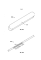
[009] Em algumas variações do dispositivo e métodos descritas aqui, um cateter pode compreender uma ou mais estruturas expansíveis. O cateter pode compreender qualquer número de estruturas expansíveis (por exemplo, zero, um, dois ou três ou mais) e cada estrutura expansível pode ser qualquer estrutura expansível adequada (por exemplo, um balão, uma gaiola expansível, entrelaçamento ou similar). A estrutura expansível ou estruturas expansíveis podem ser utilizadas para ajudar a colocar o cateter em aposição com uma parede de tecido. Em outras variações, uma ou mais estruturas expansíveis podem ser utilizadas para dilatar uma ou mais porções de um vaso sanguíneo. Em outras variações, uma ou mais estruturas expansíveis podem ser utilizadas para expandir ou de outra forma modificar o tamanho de uma fístula. Em outras variações, uma estrutura expansível pode compreender um ou mais eletrodos que podem ser ativados para distribuir energia de RF para um ou mais vasos sanguíneos, que podem restringir o fluxo de sangue através dos mesmos. Adicionalmente ou alternativamente, uma estrutura expansível pode ajudar a ancorar um cateter pelo menos temporariamente em determinada posição dentro do sistema vascular.[009] In some variations of the device and methods described here, a catheter may comprise one or more expandable structures. The catheter can comprise any number of expandable structures (e.g. zero, one, two or three or more) and each expandable structure can be any suitable expandable structure (e.g. a balloon, an expandable cage, mesh or the like). The expandable frame or expandable frames can be used to help bring the catheter into apposition with a tissue wall. In other variations, one or more expandable structures may be used to dilate one or more portions of a blood vessel. In other variations, one or more expandable structures may be used to expand or otherwise change the size of a fistula. In other variations, an expandable structure can comprise one or more electrodes that can be activated to deliver RF energy to one or more blood vessels, which can restrict blood flow therethrough. Additionally or alternatively, an expandable structure can help to anchor a catheter at least temporarily in a certain position within the vascular system.
[010] Em algumas variações um cateter pode compreender um ou mais componentes para unir ou de outra forma fixar uma porção de um primeiro vaso sanguíneo a um segundo vaso sanguíneo. Em algumas variações, um cateter pode compreender um ou mais componentes (por exemplo, um eletrodo) configurado para suprir energia elétrica, de ultrassom ou laser para o tecido. Em outras variações, um cateter pode compreender uma ou mais agulhas configuradas para distribuir um adesivo entre um primeiro vaso sanguíneo e um segundo vaso sanguíneo. Em outras variações, Em outras variações adicionais, um cateter pode ser configurado para desenvolver uma ou mais farpas, grampos ou outros implantes no tecido dos primeiro e segundo vasos sanguíneos.[010] In some variations a catheter may comprise one or more components for joining or otherwise securing a portion of a first blood vessel to a second blood vessel. In some variations, a catheter may comprise one or more components (eg, an electrode) configured to supply electrical, ultrasound, or laser energy to tissue. In other variations, a catheter may comprise one or more needles configured to deliver an adhesive between a first blood vessel and a second blood vessel. In other variations, In other additional variations, a catheter may be configured to develop one or more barbs, clamps or other implants in the tissue of the first and second blood vessels.
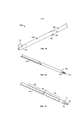
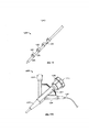
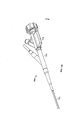
[011] As Figuras 1A a 1C apresentam diferentes vistas em perspectiva da porção distal de uma variação dos cateteres descritos aqui;[011] Figures 1A to 1C show different perspective views of the distal portion of a variation of the catheters described here;
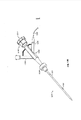
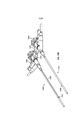
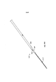
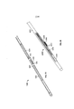
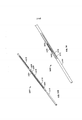
[012] As Figuras 2, 3, 4, 5, 6A, 6B, 7A, 7B e 8 apresentam porções distais das variações dos cateteres descritos aqui;[012] Figures 2, 3, 4, 5, 6A, 6B, 7A, 7B and 8 show distal portions of the variations of the catheters described here;
[013] As Figuras 9A a 9D, 10A a 10C, 11 e 12 apresentam variações dos cateteres descritos aqui compreendendo um ou mais elementos expansíveis;[013] Figures 9A to 9D, 10A to 10C, 11 and 12 show variations of the catheters described herein comprising one or more expandable elements;
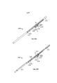
[014] As Figuras 13A e 13B apresentam as porções proximais de duas variações dos cateteres descritos aqui;[014] Figures 13A and 13B show the proximal portions of two variations of the catheters described here;
[015] A Figura 14A ilustra uma vista em perspectiva de uma variação de um cateter compreendendo uma faixa de marcador. A Figura 14B ilustra uma vista em perspectiva de uma faixa de marcador, enquanto as Figuras 14C e 14D apresentam vistas laterais de uma faixa de marcador;[015] Figure 14A illustrates a perspective view of a variation of a catheter comprising a marker band. Figure 14B illustrates a perspective view of a marker strip, while Figures 14C and 14D show side views of a marker strip;
[016] As Figuras 15A e 15B ilustram duas variações de porções proximais dos cateteres descritos aqui;[016] Figures 15A and 15B illustrate two variations of proximal portions of the catheters described here;
[017] As Figuras 16A e 16B ilustram outra variação dos cateteres descritos aqui;[017] Figures 16A and 16B illustrate another variation of the catheters described here;
[018] As Figuras 17A e 17B ilustram um método pelo qual um ímã externo pode ser utilizado para ajudar a avançar um cateter através do sistema vascular;[018] Figures 17A and 17B illustrate a method by which an external magnet can be used to help advance a catheter through the vascular system;
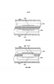
[019] As Figuras 18A e 18B apresentam variações dos cateteres compreendendo eletrodos com superfícies de ablação planas;[019] Figures 18A and 18B show variations of catheters comprising electrodes with flat ablation surfaces;
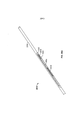
[020] As Figuras 19, 20, 21A, 21B, 22, 23, 24A e 24B apresentam porções distais das variações dos cateteres descritos aqui;[020] Figures 19, 20, 21A, 21B, 22, 23, 24A and 24B show distal portions of the variations of the catheters described herein;
[021] A Figura 25A ilustra uma vista transversal parcial de uma porção distal de uma variação dos cateteres descritos aqui. As Figuras 25B a 25D apresentam vistas em perspectiva do cateter da Figura 25A;[021] Figure 25A illustrates a partial cross-sectional view of a distal portion of a variation of the catheters described herein. Figures 25B to 25D show perspective views of the catheter of Figure 25A;
[022] A Figura 26A apresenta uma porção distal de uma variação dos cateteres descritos aqui. A Figura 26B apresenta o cateter da Figura 26A com outra variação dos cateteres descritos aqui;[022] Figure 26A shows a distal portion of a variation of the catheters described here. Figure 26B shows the catheter of Figure 26A with another variation of the catheters described herein;
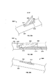
[023] As Figuras 27A e 27B apresentam duas vistas em perspectiva de uma variação dos cateteres descritos aqui. As Figuras 27C e 27D apresentam duas variações dos cateteres descritos aqui localizados nos vasos sanguíneos;[023] Figures 27A and 27B show two perspective views of a variation of the catheters described here. Figures 27C and 27D show two variations of the catheters described herein located in blood vessels;
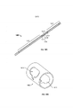
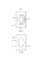
[024] As Figuras 28A e 29A apresentam duas variações dos eletrodos adequados para uso com os cateteres descritos aqui. As Figuras 28B e 29B apresentam duas variações dos cateteres que incluem os eletrodos das Figuras 28A e 29A.[024] Figures 28A and 29A present two variations of the electrodes suitable for use with the catheters described here. Figures 28B and 29B show two variations of the catheters that include the electrodes of Figures 28A and 29A.
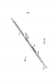
[025] As Figuras 30, 31A e 31B, 32, 33A e 33B, 34, 35A e 35B e 36 apresentam várias variações dos cateteres descritos aqui;[025] Figures 30, 31A and 31B, 32, 33A and 33B, 34, 35A and 35B and 36 show several variations of the catheters described here;
[026] As Figuras 37A e 37B ilustram vistas transversais de uma variação de um cateter compreendendo uma lâmina;[026] Figures 37A and 37B illustrate cross-sectional views of a variation of a catheter comprising a blade;
[027] As Figuras 38A e 38B apresentam uma vista em perspectiva e uma vista lateral transversal, respectivamente, de uma variação de um cateter compreendendo uma lâmina;[027] Figures 38A and 38B show a perspective view and a cross-sectional side view, respectively, of a variation of a catheter comprising a blade;
[028] A Figura 39A apresenta uma vista em perspectiva de uma variação de um cateter compreendendo uma lâmina; as Figuras 39B e 39C apresentam vistas laterais transversais do cateter ilustrado na Figura 39A.[028] Figure 39A shows a perspective view of a variation of a catheter comprising a blade; Figures 39B and 39C show cross-sectional side views of the catheter illustrated in Figure 39A.
[029] As Figuras 40A e 40B, 41 e 42 apresentam variações dos dispositivos e métodos para unir um primeiro vaso sanguíneo a um segundo vaso sanguíneo;[029] Figures 40A and 40B, 41 and 42 show variations of devices and methods for joining a first blood vessel to a second blood vessel;
[030] As Figuras 43 e 44 apresentam variações dos cateteres compreendendo fibras óticas. Descrição Detalhada[030] Figures 43 and 44 show variations of catheters comprising optical fibers. Detailed Description
[031] São descritos aqui dispositivos e métodos para a formação de uma fístula. Em algumas variações, os dispositivos e métodos podem ser utilizados para formar uma fístula entre dois vasos sanguíneos (por exemplo, uma fístula arteriovenosa entre uma artéria e uma veia ou uma fístula veno-venosa entre duas veias). Geralmente, para se formar tal fístula entre dois vasos sanguíneos, um ou mais cateteres são avançados de forma minimamente invasiva através do sistema vascular depara um local alvo. Em alguns casos, um único cateter pode ser localizado em um vaso sanguíneo para formar uma fístula com um vaso sanguíneo adjacente. Em outros casos, um sistema compreendendo múltiplos cateteres podem ser utilizados para formar uma fístula. Por exemplo, em alguns casos um cateter pode ser localizado em cada um dos dois vasos sanguíneos. Nesses casos, deve-se apreciar que cada cateter pode ou não ter a mesma configuração de elementos, e que alguns cateteres podem ser diferentes de e/ou complementares a outros cateteres, como será descrito em maiores detalhes.[031] Devices and methods for forming a fistula are described here. In some variations, devices and methods can be used to form a fistula between two blood vessels (eg, an arteriovenous fistula between an artery and a vein or a veno-venous fistula between two veins). Generally, to form such a fistula between two blood vessels, one or more catheters are minimally invasively advanced through the vascular system to a target site. In some cases, a single catheter may be located in a blood vessel to form a fistula with an adjacent blood vessel. In other cases, a system comprising multiple catheters may be used to form a fistula. For example, in some cases a catheter may be located in each of the two blood vessels. In such cases, it should be appreciated that each catheter may or may not have the same configuration of elements, and that some catheters may be different from and/or complementary to other catheters, as will be described in more detail.
[032] Um ou uma combinação de cateteres descritos aqui podem ser utilizados para formar uma fístula, como será descrito em maiores detalhes abaixo. Geralmente, cada cateter terá uma extremidade proximal, uma extremidade distal, e uma porção intermediária conectando as extremidades proximal e distal. A extremidade proximal pode compreender um ou mais adaptadores ou alças, que podem ser utilizados para ajudar a no avanço, posicionamento e controle do cateter dentro do sistema vascular, e podem ser adicionalmente utilizados para acionar um ou mais componentes do cateter e/ou introduzir um ou mais fluidos ou substâncias em e/ou através do cateter. O cateter pode compreender um ou mais elementos que podem auxiliar na formação da fístula. Em algumas variações, uma ou mais porções (por exemplo, extremidade distal e/ou porção intermediaria) do cateter pode compreender um ou mais elementos de alinhamento (por exemplo, um ou mais ímãs) que podem ajudar a alinhar o cateter com outro cateter posicionado em um vaso sanguíneo relacionado e/ou colocar os cateteres (e os vasos sanguíneos) em aproximação. Adicionalmente ou alternativamente, uma ou mais porções (por exemplo, a extremidade distal e/ou uma porção intermediária) do cateter pode compreender um ou mais mecanismos para a formação de uma fístula.[032] One or a combination of catheters described here can be used to form a fistula, as will be described in greater detail below. Generally, each catheter will have a proximal end, a distal end, and an intermediate portion connecting the proximal and distal ends. The proximal end may comprise one or more adapters or loops, which may be used to assist in advancing, positioning and controlling the catheter within the vascular system, and may additionally be used to drive one or more components of the catheter and/or introduce a or more fluids or substances in and/or through the catheter. The catheter may comprise one or more elements that may aid in fistula formation. In some variations, one or more portions (e.g., distal end and/or intermediate portion) of the catheter may comprise one or more alignment elements (e.g., one or more magnets) that can assist in aligning the catheter with another positioned catheter. into a related blood vessel and/or bring the catheters (and blood vessels) together. Additionally or alternatively, one or more portions (e.g., the distal end and/or an intermediate portion) of the catheter may comprise one or more mechanisms for forming a fistula.
[033] Os cateteres podem compreender adicionalmente um ou mais lumens ou passagens se estendendo pelo menos parcialmente ao longo de ou através do cateter e podem ser utilizados para passar um ou mais fios guia, uma ou mais drogas ou fluidos (por exemplo, agentes de contraste, fluidos de perfusão), combinações dos mesmos ou similares pelo menos parcialmente ao longo de ou através do cateter. A ponta distal do cateter pode ser configurada para auxiliar no avanço do cateter e/ou para ser não traumática. Em algumas variações, a ponta pode compreender uma ou mais porções de permuta rápida ou outros lumens para o avanço do cateter através de um fio guia. Em outras variações, a porção de ponta pode ter um fio guia fixado a ou de outra forma integralmente formado com o cateter.[033] The catheters may further comprise one or more lumens or passageways extending at least partially along or through the catheter and may be used to pass one or more guide wires, one or more drugs or fluids (e.g. contrast, perfusion fluids), combinations of the same or similar at least partially along or through the catheter. The distal tip of the catheter can be configured to aid in catheter advancement and/or to be non-traumatic. In some variations, the tip may comprise one or more quick-change portions or other lumens for advancing the catheter through a guidewire. In other variations, the tip portion may have a guide wire attached to or otherwise integrally formed with the catheter.
[034] Adicionalmente, em algumas variações os cateteres podem compreender adicionalmente um ou mais elementos expansíveis externos (por exemplo, um balão, gaiola expansível, entrelaçamento, ou similares) que podem ajudar a posicionar um cateter dentro de um vaso sanguíneo. Adicionalmente ou alternativamente, os um ou mais elementos expansíveis podem afetar o fluxo de sangue através de um ou mais vasos sanguíneos (por exemplo, pela oclusão temporária do fluxo de sangue através do vaso sanguíneo, dilatando uma ou mais porções de um vaso sanguíneo, restringindo uma ou mais porções de um vaso sanguíneo, ou similares). Em alguns casos, um ou mais elementos expansíveis podem agir para ancorar temporariamente uma porção do cateter com relação a um vaso sanguíneo. Em variações nas quais o cateter compreende um ou mais elementos de desafio de formato, como será descrito em maiores detalhes abaixo, o uso de um elemento expansível para ancorar temporariamente uma porção do cateter com relação a um vaso sanguíneo pode auxiliar na alteração do formato do cateter. Deve-se apreciar que os cateteres descritos aqui podem ter qualquer combinação dos elementos mencionados acima, cada um dos quais será descrito em maiores detalhes abaixo.[034] Additionally, in some variations the catheters may additionally comprise one or more external expandable elements (e.g., a balloon, expandable cage, braid, or the like) that can assist in positioning a catheter within a blood vessel. Additionally or alternatively, the one or more expandable elements may affect the flow of blood through one or more blood vessels (e.g., by temporarily occluding blood flow through the blood vessel, dilating one or more portions of a blood vessel, restricting one or more portions of a blood vessel, or the like). In some cases, one or more expandable elements may act to temporarily anchor a portion of the catheter with respect to a blood vessel. In variations in which the catheter comprises one or more shape-challenging elements, as will be described in greater detail below, the use of an expandable member to temporarily anchor a portion of the catheter with respect to a blood vessel may assist in altering the shape of the catheter. catheter. It should be appreciated that the catheters described herein may have any combination of the elements mentioned above, each of which will be described in greater detail below.
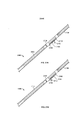
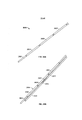
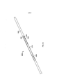
[035] As Figuras 1A a 1C apresentam uma variação ilustrativa de um cateter (100) adequado para uso na formação de uma fístula. Especificamente, a Figura 1A apresenta uma vista em perspectiva da porção distal (108) do cateter (100) com a manga (106) cobrindo pelo menos uma porção do cateter (100). A Figura 1B apresenta uma vista parcialmente transparente do cateter (100) com a manga (106) ilustrada como parcialmente transparente. A Figura 1C apresenta uma vista parcialmente em perspectiva do cateter (100) com a manga (106) e o corpo de cateter ilustrado como parcialmente transparente. Como ilustrado nessas Figuras, o cateter (100) pode compreender um eletrodo (102) possuindo uma superfície de ablação exposta (105) e um fio guia (104) fixado à mesma. Também como ilustrado encontra-se um ímã de ancoragem proximal (116), um ímã de ancoragem distal (118), e uma porção de permuta rápida (110) incluindo primeira e segunda aberturas (112) e (114) respectivamente), cada uma das quais será descrita em maiores detalhes abaixo. Para se formar uma fístula utilizando-se o cateter (100), a superfície de ablação (105) do eletrodo (102) pode ser localizada em contato elétrico com um tecido alvo, e uma corrente pode ser suprida para o eletrodo (102) para causar a ablação ou vaporizar o tecido. Componentes de cateter individuais e métodos serão descritos em maiores detalhes abaixo.[035] Figures 1A to 1C present an illustrative variation of a catheter (100) suitable for use in the formation of a fistula. Specifically, Figure 1A shows a perspective view of the distal portion (108) of the catheter (100) with the sleeve (106) covering at least a portion of the catheter (100). Figure 1B shows a partially transparent view of the catheter (100) with the sleeve (106) shown as partially transparent. Figure 1C shows a partially perspective view of the catheter (100) with the sleeve (106) and catheter body shown as partially transparent. As illustrated in these Figures, the catheter (100) may comprise an electrode (102) having an exposed ablation surface (105) and a guide wire (104) attached thereto. Also as illustrated are a proximal anchoring magnet (116), a distal anchoring magnet (118), and a quick-change portion (110) including first and second openings (112) and (114) respectively), each which will be described in more detail below. To form a fistula using the catheter (100), the ablation surface (105) of the electrode (102) may be located in electrical contact with a target tissue, and a current may be supplied to the electrode (102) to cause ablation or vaporize the tissue. Individual catheter components and methods will be described in more detail below.
[036] Como mencionado acima, os cateteres descritos aqui podem compreender um ou mais elementos de formação de uma fístula. Esses elementos de formação de fístula podem utilizar qualquer estrutura ou mecanismo capaz de cortar, causar ablação, vaporizar, dissolver, ou de outra forma remover o tecido entre vasos adjacentes, tal como, por exemplo, um ou mais mecanismos elétricos (por exemplo, um ou mais eletrodos ou dispositivos de eletrocauterização), um ou mais mecanismos mecânicos (por exemplo, uma ou mais lâminas de corte, lancetas, agulhas e similares), um ou mais mecanismos químicos (por exemplo, um ou mais dispositivos de liberação de enzima), dispositivos de cauterização criogênica, dispositivos de ablação com laser (por exemplo, uma ou mais fontes de luz de laser de fibra ótica), combinações dos mesmos ou similares. Um cateter pode ter qualquer número adequado (por exemplo, zero, um, dois, três ou quatro ou mais) e combinação desses elementos de formação de fístula, e esses elementos de formação de fístula podem ser localizados em ou em qualquer porção adequada do cateter (por exemplo, a extremidade distal, uma porção intermediária, combinações dos mesmos). Em variações onde um cateter compreende dois ou mais elementos de formação de fístula, múltiplos elementos de formação de fístula podem formar múltiplas fístulas, de forma simultânea ou sequencial. Em outras variações, múltiplos elementos de formação de fístula podem interagir para formar uma única fístula.[036] As mentioned above, the catheters described herein may comprise one or more fistula-forming elements. Such fistula-forming elements may utilize any structure or mechanism capable of cutting, ablating, vaporizing, dissolving, or otherwise removing tissue between adjacent vessels, such as, for example, one or more electrical mechanisms (e.g., a or more electrodes or electrocautery devices), one or more mechanical mechanisms (e.g., one or more cutting blades, lancets, needles, and the like), one or more chemical mechanisms (e.g., one or more enzyme-releasing devices) , cryogenic cautery devices, laser ablation devices (eg, one or more fiber optic laser light sources), combinations of the same or similar. A catheter may have any suitable number (e.g., zero, one, two, three, or four or more) and combination of such fistula-forming elements, and such fistula-forming elements may be located on or in any suitable portion of the catheter. (e.g. the distal end, an intermediate portion, combinations thereof). In variations where a catheter comprises two or more fistula forming elements, multiple fistula forming elements may form multiple fistulas, either simultaneously or sequentially. In other variations, multiple fistula-forming elements may interact to form a single fistula.
[037] Em variações onde um sistema compreendendo múltiplos cateteres é utilizado para criar uma fístula entre dois vasos sanguíneos, cada cateter pode compreender um elemento de formação de fístula, mas não precisa. Na verdade, em algumas dessas variações, apenas um cateter pode compreender um elemento de formação de fístula. Em alguns desses casos, o outro cateter ainda pode ajudar a alinhar os cateteres e/ou aproximar os vasos sanguíneos, mas pode não contribuir diretamente para a remoção do tecido. Em variações onde múltiplos cateteres compreendem, cada um, um elemento de formação de fístula, os cateteres podem ter elementos de formação de fístula complementares. Por exemplo, em variações onde dois ou mais cateteres compreendem eletrodos, como explicado em maiores detalhes abaixo, um cateter pode compreender um eletrodo que age como um eletrodo ativo, enquanto outro cateter pode compreender um eletrodo que age como um eletrodo passivo ou de aterramento.[037] In variations where a system comprising multiple catheters is used to create a fistula between two blood vessels, each catheter may comprise a fistula forming element, but need not. Indeed, in some of these variations, only one catheter may comprise a fistula-forming element. In some of these cases, the other catheter may still help to align the catheters and/or bring the blood vessels closer together, but may not directly contribute to tissue removal. In variations where multiple catheters each comprise a fistula forming element, the catheters may have complementary fistula forming elements. For example, in variations where two or more catheters comprise electrodes, as explained in greater detail below, one catheter may comprise an electrode which acts as an active electrode, while another catheter may comprise an electrode which acts as a passive or ground electrode.
[038] Como mencionado acima, em algumas variações dos cateteres descritos aqui, um cateter pode compreender um ou mais eletrodos para uso na formação de uma fístula. Geralmente, nessas variações, um cateter pode compreender um corpo de eletrodo e pelo menos um fio guia ou outro condutor fixado ao mesmo para conexão do eletrodo a um gerador eletrocirúrgico. Em algumas variações, uma ou mais porções de um fio guia podem agir como um eletrodo para causar ablação do tecido. Um cateter pode ter qualquer número adequado de eletrodos (por exemplo, zero, um, dois, três ou mais), e cada eletrodo pode ser posicionado em qualquer ponto adequado ao longo do comprimento do cateter (isso é, extremidade distal, porção intermediária, etc.) e pode ter qualquer tamanho e formato adequado, como discutido em maiores detalhes abaixo. Deve-se apreciar que quando utilizado com um gerador de corrente direta, um eletrodo pode agir como um eletrodo ativo (por exemplo, onde a corrente é transportada para longe do eletrodo para um local aterrado), dependendo da forma na qual é utilizado. Quando um cateter possuindo um eletrodo ativo é utilizado em conjunto com um cateter possuindo um ou mais eletrodos de aterramento passivos, a energia elétrica pode ter uma tendência a fluir a partir do eletrodo ativo através do tecido de intervenção e para o eletrodo passivo. Dessa forma, o par de eletrodos pode ajudar a impedir a perda de energia para o tecido circundante.[038] As mentioned above, in some variations of the catheters described here, a catheter may comprise one or more electrodes for use in forming a fistula. Generally, in these variations, a catheter may comprise an electrode body and at least one guide wire or other conductor attached thereto for connection of the electrode to an electrosurgical generator. In some variations, one or more portions of a guide wire can act as an electrode to cause tissue ablation. A catheter may have any suitable number of electrodes (e.g., zero, one, two, three or more), and each electrode may be positioned at any suitable point along the length of the catheter (i.e., distal end, middle portion, etc.) and can be of any suitable size and shape, as discussed in more detail below. It should be appreciated that when used with a direct current generator, an electrode can act as an active electrode (eg where current is carried away from the electrode to a grounded location), depending on the way in which it is used. When a catheter having an active electrode is used in conjunction with a catheter having one or more passive grounding electrodes, electrical energy may have a tendency to flow from the active electrode through the intervening tissue and to the passive electrode. In this way, the pair of electrodes can help prevent energy loss to the surrounding tissue.
[039] Em alguns casos um ou mais eletrodos podem ser conectados a um gerador eletrocirúrgico, suprimento de energia ou outro gerador de forma de onda que é configurado para gerar uma corrente alternada. Em algumas dessas variações, dois ou mais eletrodos podem ser conectados às saídas bipolares de um gerador. Em algumas dessas variações, um primeiro eletrodo é fixado à saída ativa do gerador, e um eletrodo de retorno (por exemplo, uma placa metálica grande ou porção metalizada flexível) pode ser temporariamente fixada ao paciente e conectada á saída de retorno do gerador. Em outras dessas variações, dois ou mais eletrodos podem ser fixados a uma saída ativa do gerador, e um eletrodo de retorno pode ser temporariamente fixado ao paciente e conectado à saída de retorno do gerador. Em outras variações ainda, um primeiro eletrodo pode ser fixado à saída ativa do gerador, e um segundo eletrodo pode ser fixado à saída de retorno do gerador em uma configuração de "foco monopolar".[039] In some cases one or more electrodes may be connected to an electrosurgical generator, power supply or other waveform generator that is configured to generate an alternating current. In some of these variations, two or more electrodes may be connected to the bipolar outputs of a generator. In some of these variations, a first electrode is attached to the active output of the generator, and a return electrode (eg, a large metal plate or flexible metallized portion) may be temporarily attached to the patient and connected to the return output of the generator. In other such variations, two or more electrodes may be attached to an active output of the generator, and a return electrode may be temporarily attached to the patient and connected to the return output of the generator. In still other variations, a first electrode may be attached to the active output of the generator, and a second electrode may be attached to the return output of the generator in a "monopolar focus" configuration.
[040] Geralmente, pelo menos uma porção de cada eletrodo pode ser exposta ao ambiente circundante (por exemplo, através de uma ou mais aberturas no corpo de cateter). Essa superfície exposta pode ser configurada para contatar o tecido circundante (por exemplo, uma parede do vaso sanguíneo) ou fluidos, e pode agir como uma superfície de ablação de modo que a corrente possa ser suprida para e/ou transportada do tecido através da superfície de ablação para facilitar a ablação ou vaporização do tecido. Em algumas variações, a superfície de ablação pode ser temporariamente coberta (por exemplo, por uma bainha ou tubulação) de modo que a superfície de ablação não entre em contato com o tecido. Nesses casos, a cobertura temporária pode ser movida ou removida para expor a superfície de ablação ao ambiente circundante. Em outras variações, a superfície de ablação pode ser temporariamente colocada em recesso ou mantida dentro do cateter, e em alguns desses casos, pode ser avançada para fora do cateter para contatar o tecido. A superfície de ablação não precisa ser móvel, e pode, ao invés disso, ser fixa com relação ao cateter. Adicionalmente ou alternativamente, em algumas variações uma superfície de eletrodo exposta pode compreender um revestimento poroso que permite a condução de corrente para a mesma ou da mesma enquanto impede o contato direto entre dois eletrodos, como será descrito em maiores detalhes abaixo. Os eletrodos podem ser feitos de qualquer material adequado ou combinação de materiais. Em algumas variações o eletrodo pode compreender um ou mais metais refratários. Por exemplo, um eletrodo pode compreender tungstênio, molibdênio, nióbio, tântalo, rênio, combinações ou ligas dos mesmos.[040] Generally, at least a portion of each electrode can be exposed to the surrounding environment (eg, through one or more openings in the catheter body). This exposed surface can be configured to contact surrounding tissue (e.g., a blood vessel wall) or fluids, and can act as an ablation surface so that current can be supplied to and/or transported from the tissue across the surface. ablation device to facilitate tissue ablation or vaporization. In some variations, the ablation surface may be temporarily covered (eg, by a sheath or tubing) so that the ablation surface does not contact tissue. In these cases, the temporary covering can be moved or removed to expose the ablation surface to the surrounding environment. In other variations, the ablation surface may be temporarily recessed or held within the catheter, and in some of these cases, may be advanced out of the catheter to contact tissue. The ablation surface need not be movable, and may instead be fixed with respect to the catheter. Additionally or alternatively, in some variations an exposed electrode surface may comprise a porous coating which allows current to be conducted to or therefrom while preventing direct contact between two electrodes, as will be described in greater detail below. The electrodes can be made of any suitable material or combination of materials. In some variations the electrode may comprise one or more refractory metals. For example, an electrode may comprise tungsten, molybdenum, niobium, tantalum, rhenium, combinations or alloys thereof.
[041] A superfície de ablação de eletrodo pode ter qualquer formato ou tamanho adequado para a ablação do tecido. Por exemplo, a superfície de ablação pode ser oval, circular, retangular, triangular, pentagonal, hexagonal, poligonal, de formato irregular, ou similar. Alternativamente ou adicionalmente, a superfície de ablação pode ser áspera ou de outra forma padronizada, como será descrito em maiores detalhes abaixo. Em variações onde a superfície de ablação é exposta através de uma ou mais aberturas no corpo de cateter, essas aberturas podem definir pelo menos parcialmente o tamanho e formato da superfície de ablação. Em variações onde o cateter compreende um material de ninho, como será descrito em maiores detalhes abaixo, o material de nino pode definir pelo menos parcialmente o tamanho e formato da superfície de ablação. O tamanho e formato da superfície de ablação podem ajudar a determinar o tamanho e formato da fístula resultante. A superfície de ablação pode ter qualquer comprimento adequado (por exemplo, cerca de 0,15 cm, cerca de 0,47 cm, entre cerca de 0,2 e cerca de 0,5 cm, entre cerca de 0,2 e cerca de 0,19 cm, cerca de 0,38 cm, e cerca de 0,5 cm e similares) e qualquer largura adequada (por exemplo, 0,07 cm, cerca de 0,15 cm, entre cerca de 0,06 cm e cerca de 0,07 cm, entre cerca de 0,06 e cerca de 0,12 cm, entre cerca de 0,12 e cerca de 0,19 cm, e similares). Em variações onde a superfície de ablação é circular, cilíndrica ou semiesférica, a superfície de ablação pode ter qualquer raio adequado (por exemplo, cerca de 0,07 cm, cerca de 0,10 cm, cerca de 0,12 cm, e similares). Em variações onde uma porção do eletrodo se estende para fora de uma porção do cateter, como será descrito em maiores detalhes abaixo, a superfície de ablação pode ter qualquer altura adequada (por exemplo, cerca de 0,25 mm, cerca de 0,5 mm, cerca de 0,75 mm, cerca de 1 mm, entre cerca de 1 e cerca de 1,5 mm, entre cerca de 0,25 mm e cerca de 1 mm, entre cerca de 0,25 mm e cerca de 0,75 mm, mais que cerca de 1,5 mm ou similares).[041] The electrode ablation surface can be of any shape or size suitable for tissue ablation. For example, the ablation surface may be oval, circular, rectangular, triangular, pentagonal, hexagonal, polygonal, irregularly shaped, or similar. Alternatively or additionally, the ablation surface may be rough or otherwise patterned, as will be described in greater detail below. In variations where the ablation surface is exposed through one or more openings in the catheter body, those openings may at least partially define the size and shape of the ablation surface. In variations where the catheter comprises a nest material, as will be described in greater detail below, the nest material may at least partially define the size and shape of the ablation surface. The size and shape of the ablation surface can help determine the size and shape of the resulting fistula. The ablation surface can be any suitable length (e.g., about 0.15 cm, about 0.47 cm, between about 0.2 and about 0.5 cm, between about 0.2 and about 0.19 cm, about 0.38 cm, and about 0.5 cm and the like) and any suitable width (e.g., 0.07 cm, about 0.15 cm, between about 0.06 cm and about 0.07 cm, between about 0.06 and about 0.12 cm, between about 0.12 and about 0.19 cm, and the like). In variations where the ablation surface is circular, cylindrical, or hemispherical, the ablation surface may have any suitable radius (e.g., about 0.07 cm, about 0.10 cm, about 0.12 cm, and the like ). In variations where a portion of the electrode extends out of a portion of the catheter, as will be described in more detail below, the ablation surface can be of any suitable height (e.g., about 0.25 mm, about 0.5 mm). mm, about 0.75 mm, about 1 mm, between about 1 and about 1.5 mm, between about 0.25 mm and about 1 mm, between about 0.25 mm and about 0 .75 mm, more than about 1.5 mm or the like).
[042] Quando dois ou mais eletrodos são utilizados em conjunto para formar uma fístula, os dois ou mais eletrodos podem ter tamanhos diferentes. Por exemplo, em algumas variações, um primeiro eletrodo possuindo uma superfície de ablação maior (por exemplo, uma superfície de ablação retangular de cerca de 0,50 cm (0,2 polegadas) por cerca de 0,12 cm (0,05 polegadas)) pode ser localizada em uma artéria, e um segundo eletrodo possuindo uma superfície de ablação menor (por exemplo, uma superfície de ablação retangular de cerca de 0,25 cm (0,1 polegadas) por cerca de 0,12 cm (0,05 polegadas)) pode ser localizada em uma veia. Nessas variações, quando um sinal de RF (por exemplo, uma forma de onda sinusoidal, ou similar) de uma determinada potência (por exemplo, 40 W) é aplicada aos eletrodos para formar uma fístula entre a artéria e a veia, o segundo eletrodo pode ter uma densidade de corrente maior do que o primeiro eletrodo em virtude de sua superfície de ablação menor. Isso pode fazer com que a formação da fístula comece na veia, e se propague através da artéria. A formação direcional da fístula pode ajudar a impedir o extravasamento (por exemplo, perda de sangue para o tecido circundante) em casos nos quais uma fístula não é totalmente formada entre uma artéria e uma veia (como a formação de fístula parcial começando em uma artéria pode ter um maior risco de extravasamento do que a formação de fístula parcial começando em uma veia).[042] When two or more electrodes are used together to form a fistula, the two or more electrodes may have different sizes. For example, in some variations, a first electrode having a larger ablation surface (e.g., a rectangular ablation surface of about 0.50 cm (0.2 inches) by about 0.12 cm (0.05 inches) )) can be located in an artery, and a second electrode having a smaller ablation surface (e.g., a rectangular ablation surface of about 0.25 cm (0.1 inch) by about 0.12 cm (0 .05 inches)) can be located in a vein. In these variations, when an RF signal (e.g. a sinusoidal waveform, or similar) of a certain power (e.g. 40 W) is applied to the electrodes to form a fistula between the artery and vein, the second electrode may have a higher current density than the first electrode because of its smaller ablation surface. This can cause fistula formation to start in the vein, and spread through the artery. Directional fistula formation can help prevent extravasation (e.g., blood loss into surrounding tissue) in cases where a fistula is not fully formed between an artery and a vein (such as partial fistula formation starting in an artery may have a higher risk of extravasation than partial fistula formation starting in a vein).
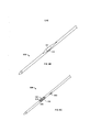
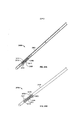
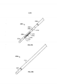
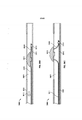
[043] Em algumas variações, a superfície de ablação pode ser nivelada com uma superfície externa do corpo de cateter. A Figura 2 ilustra uma variação do cateter (200) compreendendo um corpo de eletrodo (202) possuindo uma superfície de ablação (205). Além disso, é ilustrado o fio guia (204), o ímã de ancoragem proximal (206), e o ímã de ancoragem distal (208). Como ilustrado na Figura 2, a superfície de ablação (205) pode ser exposta através do cateter (200) e pode ser substancialmente nivelada com a superfície externa do cateter (200). Enquanto ilustrado na Figura 2 como possuindo um corpo de eletrodo cilíndrico (202) com uma superfície de ablação retangular arredondada (205), deve-se apreciar que o corpo de eletrodo (202) pode ter qualquer superfície de ablação de formato adequado (205), tal como mencionado acima. Enquanto o cateter (200) é ilustrado na Figura 2 como compreendendo um ímã de ancoragem proximal (206) e distal (208), deve-se apreciar que o cateter (200) pode ter quaisquer elementos de alinhamento ou combinações de elementos de alinhamento como descrito em maiores detalhes abaixo, ou pode não compreender qualquer elemento de alinhamento.[043] In some variations, the ablation surface may be flush with an external surface of the catheter body. Figure 2 illustrates a variation of the catheter (200) comprising an electrode body (202) having an ablation surface (205). In addition, the guide wire (204), the proximal anchoring magnet (206), and the distal anchoring magnet (208) are illustrated. As illustrated in Figure 2, the ablation surface (205) may be exposed through the catheter (200) and may be substantially flush with the outer surface of the catheter (200). While illustrated in Figure 2 as having a cylindrical electrode body (202) with a rounded rectangular ablation surface (205), it should be appreciated that the electrode body (202) can have any suitably shaped ablation surface (205) , as mentioned above. While the catheter (200) is illustrated in Figure 2 as comprising a proximal (206) and a distal (208) anchoring magnet, it should be appreciated that the catheter (200) may have any alignment elements or combinations of alignment elements such as described in more detail below, or may not comprise any alignment elements.
[044] Como ilustrado na Figura 2, a superfície de ablação (205) pode ser nivelada com o cateter (200), e, dessa forma, pode ter uma superfície arredondada. Em outras variações do dispositivo descrito aqui, um cateter pode compreender um eletrodo onde uma ou mais porções da superfície de ablação podem ser planas. Por exemplo, a Figura 18A e 18B ilustram vistas de extremidade de duas variações de cateteres possuindo superfícies de ablação planas. A Figura 18A ilustra uma primeira variação do cateter (1800) compreendendo um corpo de cateter (1802) e um eletrodo (1804) compreendendo uma superfície de ablação plana (1806). Uma superfície de ablação plana (1806) pode ajudar a fornecer uma aposição de tecido melhor entre o eletrodo (1804) e o tecido (não ilustrado). Especificamente, quando dois cateteres, cada um compreendendo um eletrodo possuindo uma superfície de ablação plana (tal como a superfície de ablação (1806)), são colocados em diferentes vasos sanguíneos, e são colocados mais perto (por exemplo, através de um ou mais dos elementos de alinhamento ou elementos de alteração de formato descritos em maiores detalhes abaixo), as duas superfícies de ablação podem fazer com que o tecido de vaso achate pelo menos temporariamente entre os mesmos. Isso pode aumentar o isolamento elétrico do tecido achatado (por exemplo, a corrente suprida para um eletrodo ativo terá que passar através do tecido achatado à medida que percorre para o eletrodo de aterramento, ao invés de ser perdida para outros fluidos ou tecido circundante), que pode auxiliar na formação da fístula.[044] As illustrated in Figure 2, the ablation surface (205) can be flush with the catheter (200), and thus can have a rounded surface. In other variations of the device described herein, a catheter may comprise an electrode where one or more portions of the ablation surface may be flat. For example, Figures 18A and 18B illustrate end views of two variations of catheters having flat ablation surfaces. Figure 18A illustrates a first variation of the catheter (1800) comprising a catheter body (1802) and an electrode (1804) comprising a flat ablation surface (1806). A flat ablation surface (1806) can help provide better tissue apposition between the electrode (1804) and tissue (not shown). Specifically, when two catheters, each comprising an electrode having a flat ablation surface (such as the ablation surface (1806)), are placed in different blood vessels, and are placed closer together (e.g., through one or more of the alignment elements or shape-altering elements described in more detail below), the two ablation surfaces can cause the vessel tissue to flatten at least temporarily therebetween. This can increase the electrical isolation of the flat tissue (for example, current supplied to an active electrode will have to pass through the flat tissue as it travels to the grounding electrode, rather than being lost to other fluids or surrounding tissue), which may aid in fistula formation.
[045] Apesar de a variação da superfície de ablação (1806) ilustrada na Figura 18A poder não ser completamente nivelada com a superfície externa do corpo de cateter (1802), o plano da superfície de ablação plana (1806) ilustrado não se projeta além da borda do corpo de cateter (1802). Em outras variações, no entanto, uma superfície de ablação plana pode ser colocada em recesso dentro do corpo de cateter, ou pode se projetar a partir daí. Por exemplo, a Figura 18B ilustra outra variação do cateter (1808) compreendendo um corpo de cateter (1810) e um eletrodo (1812) compreendendo uma superfície de ablação plana (1814). Como ilustrado aqui, o plano da superfície de ablação (1814) pode se projetar por uma distância (x) a partir do corpo de cateter (1810). Essa distância (x) pode ser qualquer distância adequada, tal como, por exemplo, cerca de 0,25 mm, cerca de 0,5 mm, cerca de 0,75 mm, cerca de 1 mm, entre cerca de 0,1 e cerca de 1,5 mm, entre cerca de 0,25 e cerca de 1 mm, entre cerca de 0,25 e cerca de 0,75 mm, ou similares. Uma superfície de ablação projetada (1814) pode pressionar para dentro do tecido à medida que o cateter (1808) é trazido na direção de outro cateter, que pode ajudar a aumentar a aposição de tecido com a superfície de ablação, que pode auxiliar na ablação do tecido. Em algumas variações, o eletrodo pode ser configurado de modo que a distância (x) seja ajustável. Por exemplo, nessas variações, uma ou mais porções do dispositivo (por exemplo, uma haste, fio guia, ou outro mecanismo de acionamento) pode ajustar a protuberância do dispositivo. Por exemplo, em algumas variações, a distância (x) pode ser ajustável entre cerca de 0 mm e cerca de 1,5 mm, entre cerca de 0 mm e cerca de 1,0 mm, entre cerca de 0 mm e cerca de 0,5 mm, entre cerca de 0,25 mm e cerca de 0,75 mm e similares. Deve-se apreciar também que a superfície de ablação pode ser configurada para mover de uma posição com recessos e uma posição com projeção.[045] While the variation of the ablation surface (1806) illustrated in Figure 18A may not be completely flush with the outer surface of the catheter body (1802), the plane of the flat ablation surface (1806) illustrated does not protrude beyond from the edge of the catheter body (1802). In other variations, however, a flat ablation surface may be recessed within the catheter body, or may protrude from there. For example, Figure 18B illustrates another variation of the catheter (1808) comprising a catheter body (1810) and an electrode (1812) comprising a flat ablation surface (1814). As illustrated here, the plane of the ablation surface (1814) may project a distance (x) from the catheter body (1810). That distance (x) can be any suitable distance, such as, for example, about 0.25 mm, about 0.5 mm, about 0.75 mm, about 1 mm, between about 0.1 and about 1.5 mm, between about 0.25 and about 1 mm, between about 0.25 and about 0.75 mm, or the like. A projected ablation surface (1814) can press into tissue as the catheter (1808) is brought toward another catheter, which can help increase tissue apposition with the ablation surface, which can aid in ablation. of the fabric. In some variations, the electrode can be configured so that the distance (x) is adjustable. For example, in these variations, one or more portions of the device (e.g., a rod, guide wire, or other drive mechanism) may adjust the bulge of the device. For example, in some variations, the distance (x) may be adjustable between about 0 mm and about 1.5 mm, between about 0 mm and about 1.0 mm, between about 0 mm and about 0 .5 mm, between about 0.25 mm and about 0.75 mm and the like. It should also be appreciated that the ablation surface can be configured to move from a recessed position to a projection position.
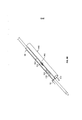
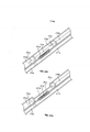
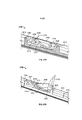
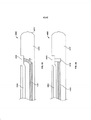
[046] Em algumas variações, uma ou mais superfícies de ablação de um eletrodo podem ser padronizadas, mas não precisam ser. A Figura 28A ilustra uma primeira variação do eletrodo (2800) compreendendo uma superfície (2802). Como ilustrado aqui, a superfície (2802) pode ser plana, e pode ser feita de um material condutor. A superfície (2802) pode agir como uma superfície de ablação quando o eletrodo (2800) é utilizado com um ou mais dos cateteres descritos aqui. Por exemplo, a Figura 28B ilustra uma variação do cateter (2804) compreendendo o eletrodo (2800) pelo menos parcialmente alojado em um material de nino (2806) dentro do corpo de cateter (2808). Como ilustrado aqui, a superfície (2802) pode agir como uma superfície de ablação. Deve-se apreciar que enquanto ilustrado na Figura 28B como compreendendo uma pluralidade de ímãs de acoplamento (2810) (que serão descritos em maiores detalhes abaixo) localizados tanto de forma proximal quanto distal com relação ao eletrodo (2800), deve-se apreciar que o cateter (2804) pode compreender qualquer elemento de alinhamento adequado ou combinações de elementos de alinhamento como descrito em maiores detalhes abaixo.[046] In some variations, one or more ablation surfaces of an electrode may be patterned, but need not be. Figure 28A illustrates a first variation of the electrode (2800) comprising a surface (2802). As illustrated here,
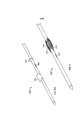
[047] A Figura 29A ilustra uma segunda variação de um eletrodo (2900) compreendendo uma superfície padronizada (2902). Como ilustrado aqui, o eletrodo (2900) pode compreender um corpo (2904) feito de um material condutor. Um primeiro lado de corpo (2904) pode compreender uma pluralidade de canais (2906) que podem definir uma pluralidade de projeções (2908), cada uma possuindo uma superfície elevada (2910). Os canais (2906) podem ser pelo menos parcialmente preenchidos com um material de encapsulamento não condutor (não ilustrado) tal como, por exemplo, um ou mais materiais cerâmicos, parileno, uma ou mais resinas poliméricas (por exemplo, poliéterimida polieteretercetona, uma ou mais resinas fenólicas, ou similares), sílica, um ou mais óxidos de metal (por exemplo, óxido de alumínio), combinações dos mesmos e similares. Por exemplo, a Figura 29B ilustra uma variação do cateter (2912) compreendendo eletrodo (2900) pelo menos parcialmente alojado em um material de ninho (2913) dentro do corpo de cateter (2915). Como ilustrado aqui, um material de encapsulamento (2914) pode preencher os canais do eletrodo (2900) de modo que o material de encapsulamento (2914) e as superfícies elevadas (2910) formem uma superfície padronizada plana (2902). A superfície padronizada (2902) pode ser exposta através do corpo de cateter (2915), e pode agir como uma superfície de ablação, como será descrito imediatamente abaixo. Deve-se apreciar que enquanto ilustrado a Figura 29B como compreendendo uma pluralidade de ímãs de acoplamento (2916) (que serão descritos em maiores detalhes abaixo), localizados tanto de forma proximal quanto distal com relação ao eletrodo (2900), deve-se apreciar que o cateter (2912) pode compreender quaisquer elementos de alinhamento ou combinações de elementos de alinhamento como descrito em maiores detalhes abaixo.[047] Figure 29A illustrates a second variation of an electrode (2900) comprising a patterned surface (2902). As illustrated here, the electrode (2900) may comprise a body (2904) made of a conductive material. A first body side (2904) may comprise a plurality of channels (2906) which may define a plurality of projections (2908), each having a raised surface (2910). Channels (2906) may be at least partially filled with a non-conductive encapsulating material (not shown) such as, for example, one or more ceramic materials, parylene, one or more polymeric resins (e.g., polyetherimide polyetheretherketone, one or more plus phenolic resins, or the like), silica, one or more metal oxides (e.g. aluminum oxide), combinations thereof, and the like. For example, Figure 29B illustrates a variation of the catheter (2912) comprising electrode (2900) at least partially housed in a nest material (2913) within the catheter body (2915). As illustrated here, a potting material (2914) can fill the electrode channels (2900) so that the potting material (2914) and raised surfaces (2910) form a flat patterned surface (2902). The patterned surface (2902) may be exposed through the catheter body (2915), and may act as an ablation surface, as will be described immediately below. It should be appreciated that while Figure 29B is illustrated as comprising a plurality of coupling magnets (2916) (which will be described in greater detail below), located both proximally and distally with respect to the electrode (2900), it should be appreciated that the catheter (2912) may comprise any alignment elements or combinations of alignment elements as described in greater detail below.
[048] Quando a superfície padronizada (2902) é utilizada como uma superfície de ablação, as superfícies elevadas (2910) das projeções (2908) podem ser capazes de conduzir a energia elétrica para o tecido, enquanto o material de encapsulamento (2914) pode impedir ou resistir ao fluxo de energia através do mesmo. Visto que apenas uma porção da superfície padronizada (2902) pode ser condutora através de superfícies elevadas (2910), a área de eletrodo efetiva fornecida pela superfície padronizada (2902) é reduzida. Quando uma saída de energia é aplicada a um eletrodo, a área de eletrodo efetiva reduzida pode aumentar a densidade de corrente nas porções condutoras do eletrodo (por exemplo, superfícies elevadas condutoras (2910) do eletrodo (2900). A corrente pode acumular nas bordas das superfícies elevadas (2910) e a densidade de corrente aumentada pode promover a centelhação da corrente entre eletrodos, o que pode auxiliar na ablação ou vaporização do tecido.[048] When the patterned surface (2902) is used as an ablation surface, the raised surfaces (2910) of the projections (2908) may be able to conduct electrical energy to the tissue, while the encapsulating material (2914) may prevent or resist the flow of energy through it. Since only a portion of the patterned surface (2902) can be conductive through raised surfaces (2910), the effective electrode area provided by the patterned surface (2902) is reduced. When a power output is applied to an electrode, the reduced effective electrode area can increase the current density in the conductive portions of the electrode (eg, raised conductive surfaces (2910) of the electrode (2900). Current may accumulate at the edges of the raised surfaces (2910) and the increased current density can promote sparking of current between electrodes, which can aid in tissue ablation or vaporization.
[049] Enquanto ilustrado nas Figuras 29A e 29B como sendo triangular ou quadrado e área de seção transversal, as projeções (2908) (e suas superfícies elevadas (2910)) podem ter qualquer formato ou formatos transversais adequados tal como, por exemplo, retângulos, trapezoideoides, círculos, ovais, polígonos, formatos com geometria irregular, ou similares. As projeções (2908) e os canais (2906) podem ser formados de qualquer forma adequada. Em algumas variações, um ou mais canais podem ser formados (por exemplo, por corte, gravação, entalhe ou similares) em um bloco de material (tal como o eletrodo (2800) descrito acima com relação às Figuras 28A e 28B) para definir as projeções (2908). Em outras variações, uma ou mais projeções podem ser formadas separadamente de um elemento base, e então podem ser fixadas ao elemento base.[049] While illustrated in Figures 29A and 29B as being triangular or square and cross-sectional area, the projections (2908) (and their raised surfaces (2910)) may have any suitable cross-sectional shape or shapes such as, for example, rectangles , trapezoids, circles, ovals, polygons, irregular geometry shapes, or the like. Projections (2908) and channels (2906) may be formed in any suitable way. In some variations, one or more channels may be formed (e.g., by cutting, engraving, notching or the like) in a block of material (such as the electrode (2800) described above with respect to Figures 28A and 28B) to define the projections (2908). In other variations, one or more projections can be formed separately from a base element, and then can be attached to the base element.
[050] Em variações onde um cateter compreende uma superfície de ablação plana, a superfície de ablação plana pode ter qualquer formato transversal adequado (por exemplo, um círculo, oval, triângulo, quadrado, retângulo, pentágono, hexágono, outro polígono, formato irregular ou similares). Adicionalmente ou alternativamente, a superfície de ablação pode ser padronizada, tal como descrito em maiores detalhes acima. A Figura 3 ilustra uma variação do cateter (300) compreendendo um corpo de eletrodo (310) com uma superfície de ablação hexagonal (311) se projetando a partir do cateter (300) Também ilustrados aqui estão o ímã de ancoragem proximal (302), o ímã de ancoragem distal (304), um lúmen (308) e um condutor elétrico concêntrico (314), cada um dos quais será descrito em maiores detalhes abaixo. Adicionalmente, enquanto as superfícies de ablação planas (1806) e (1814) são ilustradas nas Figuras 18A e 18B, respectivamente como sendo paralelas aos corpos de cateter ((1802) e (1804), respectivamente), deve-se apreciar que uma superfície de ablação plana pode ser angulada com relação a um corpo de cateter. Deve-se apreciar também que o eletrodo pode ter uma superfície de ablação que se projeta a partir do corpo de cateter, mas não compreende uma superfície plana. Por exemplo, em algumas variações, com uma superfície de ablação (103) do cateter (100) ilustrada nas Figuras 1A a 1C, e descrito em maiores detalhes abaixo, a superfície de ablação pode ser hemisférica.[050] In variations where a catheter comprises a flat ablation surface, the flat ablation surface may have any suitable transverse shape (e.g. a circle, oval, triangle, square, rectangle, pentagon, hexagon, other polygon, irregular shape or similar). Additionally or alternatively, the ablation surface may be patterned, as described in greater detail above. Figure 3 illustrates a variation of the catheter (300) comprising an electrode body (310) with a hexagonal ablation surface (311) protruding from the catheter (300). Also illustrated here are the proximal anchoring magnet (302), the distal anchoring magnet (304), a lumen (308) and a concentric electrical conductor (314), each of which will be described in greater detail below. Additionally, while the flat ablation surfaces (1806) and (1814) are illustrated in Figures 18A and 18B, respectively, as being parallel to the catheter bodies ((1802) and (1804), respectively), it should be appreciated that a surface ablation device can be angled with respect to a catheter body. It should also be appreciated that the electrode may have an ablation surface that projects from the catheter body, but does not comprise a flat surface. For example, in some variations, with an ablation surface (103) of the catheter (100) illustrated in Figures 1A to 1C, and described in greater detail below, the ablation surface may be hemispherical.
[051] Nas variações onde uma ou mais porções de um corpo de eletrodo se projeta a partir do corpo de cateter, uma ou mais porções do cateter podem afunilar para ajudar a reduzir o trauma que pode ser causado pela superfície de ablação projetada (ou bordas da mesma) à medida que um cateter é avançado através de um vaso sanguíneo. Em algumas variações, a superfície de ablação propriamente dita pode ser afunilada. Em outras variações, um ou mais componentes adicionais, tal como o corpo de cateter ou um material para aninhar o eletrodo (como será descrito em maiores detalhes abaixo), pode afunilar para a superfície de ablação. Por exemplo, a Figura 4 apresenta um cateter de variação (400) compreendendo um eletrodo (402) possuindo uma superfície de ablação (404) se projetando a partir da superfície do cateter (400). Também ilustrado aqui é o material de ninho (406) cobrindo parcialmente o eletrodo (402). Como ilustrado na Figura 4, o material de ninho (406) pode afunilar a partir da superfície do cateter (400) para a superfície de ablação (404), o que pode ajudar a minimizar o trauma de tecido.[051] In variations where one or more portions of an electrode body protrudes from the catheter body, one or more portions of the catheter may taper to help reduce trauma that may be caused by the projected ablation surface (or edges). thereof) as a catheter is advanced through a blood vessel. In some variations, the ablation surface itself may be tapered. In other variations, one or more additional components, such as the catheter body or an electrode nesting material (as will be described in greater detail below), may taper to the ablation surface. For example, Figure 4 shows a variation catheter (400) comprising an electrode (402) having an ablation surface (404) projecting from the surface of the catheter (400). Also illustrated here is nest material (406) partially covering the electrode (402). As illustrated in Figure 4, the nest material (406) can taper from the catheter surface (400) to the ablation surface (404), which can help minimize tissue trauma.
[052] Como mencionado imediatamente acima, em algumas variações, uma ou mais porções de um eletrodo podem ser pelo menos parcialmente cobertas ou alojadas por um material de ninho. Na verdade, em algumas dessas variações todo o corpo de eletrodo exceto pela superfície de ablação é coberto por um material de ninho. O material de ninho pode servir várias finalidades úteis. Como descrito imediatamente acima, o material de nino pode ajudar a impedir danos causados pelo eletrodo ao tecido à medida que o cateter é avançado através de um vaso sanguíneo. Em algumas variações, o material de ninho pode manter um eletrodo no lugar com relação a um ou mais outros eletrodos de um cateter (por exemplo, um ou mais elementos de alinhamento, ou similares). Adicionalmente, em alguns casos, o material de ninho pode isolar o corpo de eletrodo do tecido circundante ou outras porções do cateter, o que pode proteger as outras porções do cateter. Por exemplo, o isolamento térmico fornecido pelo material de ninho pode proteger outros componentes de cateter contra o calor que pode ser gerado pelo eletrodo. Adicionalmente ou alternativamente, o isolamento elétrico fornecido pelo material de ninho pode ajudar a minimizar a opera de corrente para outras porções do cateter ou tecido circundante. O material de ninho pode ser feito de qualquer material termicamente e/ou eletricamente resistente. Exemplos de materiais de ninho adequados incluem, mas não estão limitados a materiais cerâmicos, parileno, uma ou mais resinas poliméricas (por exemplo, poliéterimida, polieteretercetona, uma ou mais resinas fenólicas, ou similares), sílica, um ou mais óxidos de metal (por exemplo, óxido de alumínio), combinações dos mesmos, ou similares. Em alguns casos, o material de ninho pode ser um sólido usinado ou pode ser moldado. Em outros casos, o material de ninho pode ser plasma pulverizado, revestido ou de outra forma depositado em uma ou mais porções do eletrodo. Deve-se apreciar também que nas variações onde uma ou mais porções do eletrodo são móveis com relação ao cateter, o material de ninho pode ou não ser móvel também com relação ao cateter. O material de ninho e o eletrodo podem mover em conjunto, mas não precisam fazê-lo. Em algumas dessas variações, uma ou mais peças/porções do material de ninho podem mover com o eletrodo, enquanto uma ou mais peças/porções do material de ninho permanecem fixadas com relação ao cateter. Adicionalmente, o material de ninho pode ser configurado para alojar ou de outra forma manter um ou mais elementos de alinhamento (por exemplo, um ou mais ímãs) como será descrito em maiores detalhes abaixo.[052] As mentioned immediately above, in some variations, one or more portions of an electrode may be at least partially covered or housed by a nest material. In fact, in some of these variations the entire electrode body except for the ablation surface is covered by a nest material. Nest material can serve several useful purposes. As described immediately above, the nino material can help prevent electrode damage to tissue as the catheter is advanced through a blood vessel. In some variations, the nest material may hold an electrode in place with respect to one or more other electrodes on a catheter (eg, one or more alignment elements, or the like). Additionally, in some cases, the nest material may isolate the electrode body from surrounding tissue or other portions of the catheter, which may protect other portions of the catheter. For example, the thermal insulation provided by the nest material can protect other catheter components from the heat that can be generated by the electrode. Additionally or alternatively, the electrical insulation provided by the nest material can help to minimize current flow to other portions of the catheter or surrounding tissue. The nesting material can be made of any thermally and/or electrically resistant material. Examples of suitable nest materials include, but are not limited to, ceramic materials, parylene, one or more polymeric resins (e.g., polyetherimide, polyetheretherketone, one or more phenolic resins, or the like), silica, one or more metal oxides ( e.g. aluminum oxide), combinations thereof, or the like. In some cases, the nest material may be a machined solid or it may be molded. In other cases, the nest material may be plasma sprayed, coated, or otherwise deposited on one or more portions of the electrode. It should also be appreciated that in variations where one or more portions of the electrode are movable with respect to the catheter, the nest material may or may not be movable with respect to the catheter as well. Nest material and electrode can move together, but do not have to. In some of these variations, one or more pieces/portions of the nest material may move with the electrode, while one or more pieces/portions of the nest material remain fixed with respect to the catheter. Additionally, the nest material may be configured to house or otherwise maintain one or more alignment elements (e.g., one or more magnets) as will be described in greater detail below.
[053] Em algumas variações, um material de ninho pode fornecer a dissipação de calor direcionada, de modo que o calor seja direcionado na direção do centro da superfície de ablação para longe da borda da superfície de ablação. Por exemplo, o material de ninho pode ser feito de vários materiais com diferentes propriedades de transferência de calor, onde o material de ninho perto da borda da superfície de ablação pode ser feito de um material que é resistente à transferência de calor, enquanto o material de ninho perto do centro da superfície de ablação pode ser feito de um material que possua propriedades de transferência de calor eficientes. As posições intermediárias entre a borda e o centro da superfície de ablação podem ter propriedades de transferência de calor intermediárias. Alternativamente, o material de ninho pode ser feito de um material único cuja densidade varie da borda para o centro da superfície de ablação, por exemplo, o material da região de borda pode ter uma densidade que é maior do que a densidade do material na região central. Qualquer material de ninho de calor e/ou corrente adequado e configurações podem ser utilizados para direcionar ou de outra forma regular a temperatura e/ou a corrente que possam ser um resultado da ativação do eletrodo.[053] In some variations, a nest material may provide targeted heat dissipation such that heat is directed toward the center of the ablation surface away from the edge of the ablation surface. For example, the nest material can be made of various materials with different heat transfer properties, where the nest material near the edge of the ablation surface can be made of a material that is resistant to heat transfer, while the material nest near the center of the ablation surface can be made of a material that has efficient heat transfer properties. Intermediate positions between the edge and center of the ablation surface may have intermediate heat transfer properties. Alternatively, the nest material may be made of a single material whose density varies from the edge to the center of the ablation surface, for example, the material in the edge region may have a density that is greater than the density of the material in the region. central. Any suitable heat and/or current nest material and settings may be used to direct or otherwise regulate the temperature and/or current that may be a result of electrode activation.
[054] Como mencionado acima, um material de ninho pode ajudar a proteger ou isolar uma ou mais porções de um corpo de eletrodo do tecido circundante. Apesar de o corpo de cateter poder cobrir uma ou mais porções de um material de ninho, o corpo de cateter não precisa fazer isso. Por exemplo, a Figura 19 ilustra uma variação do cateter (1900). Ilustrado aqui estão o corpo de cateter distal (1902), o corpo de cateter proximal (1904), e o material de ninho (1906) alojando o eletrodo (1908) e ímãs de acoplamento (1910). Nessas variações, os corpos de cateter proximal (1904) e distal (1902) podem ser fixados ao material de ninho (1906) de modo que uma circunferência de pelo menos uma porção do material de ninho (1906) anão seja coberta por um corpo de cateter. Nesses casos, o diâmetro do material de ninho (1906) e o eletrodo (1908) pode ser aumentado, o que pode permitir que o tamanho da superfície de ablação do eletrodo (1908) seja aumentado sem aumentar o diâmetro geral do cateter (1900).[054] As mentioned above, a nest material can help protect or isolate one or more portions of an electrode body from the surrounding tissue. Although the catheter body may cover one or more portions of a nest material, the catheter body does not need to do so. For example, Figure 19 illustrates a variation of the catheter (1900). Illustrated here are the distal catheter body (1902), the proximal catheter body (1904), and the nest material (1906) housing the electrode (1908) and coupling magnets (1910). In these variations, the proximal (1904) and distal (1902) catheter bodies may be attached to the nest material (1906) so that a circumference of at least a portion of the dwarf nest material (1906) is covered by a nest material (1906) body. catheter. In such cases, the diameter of the nest material (1906) and electrode (1908) can be increased, which may allow the size of the ablation surface of the electrode (1908) to be increased without increasing the overall diameter of the catheter (1900) .
[055] Em outras variações dos cateteres descritos aqui, uma superfície de ablação pode ser pelo menos parcialmente colocada em recesso dentro de uma superfície do cateter. Em alguns casos, o contato direto entre uma superfície de eletrodo e um vaso sanguíneo pode resultar na deposição de carbono na superfície durante a ablação de tecido. Como tal, uma superfície de ablação com recesso pode ajudar a causar a ablação do tecido enquanto minimiza o acúmulo de carbono na superfície de ablação pelo fornecimento do espaçamento entre a superfície de ablação e a parede do vaso sanguíneo. Especificamente, quando um cateter é localizado contra uma parede do vaso sanguíneo, o sangue ou outro fluido pode ser temporariamente aprisionado dentro da porção com recesso. O sangue pode fornecer um meio de condução eficiente para ajudar a transferir a energia de ablação para uma parede de vaso sanguíneo sem o acúmulo de carbono na superfície de ablação, o que pode ajudar a impedir ou de outra forma reduzir a degradação do eletrodo. A Figura 5 ilustra uma variação do cateter (500) compreendendo um eletrodo (502) com uma superfície de ablação de eletrodo com recesso (504). Também ilustrado é um material de ninho (506) cobrindo pelo menos parcialmente o eletrodo (502). Como notado acima, o material de ninho (506) pode ajudar a separar a superfície de ablação isolada (504) e o eletrodo (502) dos componentes restantes do cateter (500). O tamanho, formato e profundidade da abertura podem ser determinados em parte pelo volume desejado de sangue que deve ser mantido ou de outra forma aprisionado na porção com recesso do cateter (500).[055] In other variations of the catheters described herein, an ablation surface may be at least partially recessed within a surface of the catheter. In some cases, direct contact between an electrode surface and a blood vessel can result in carbon deposition on the surface during tissue ablation. As such, a recessed ablation surface can help ablate tissue while minimizing carbon buildup on the ablation surface by providing the spacing between the ablation surface and the blood vessel wall. Specifically, when a catheter is located against a blood vessel wall, blood or other fluid may be temporarily trapped within the recessed portion. Blood can provide an efficient conduction medium to help transfer ablation energy to a blood vessel wall without carbon buildup on the ablation surface, which can help prevent or otherwise reduce lead degradation. Figure 5 illustrates a variation of the catheter (500) comprising an electrode (502) with a recessed electrode ablation surface (504). Also illustrated is a nest material (506) at least partially covering the electrode (502). As noted above, the nest material (506) can help separate the isolated ablation surface (504) and electrode (502) from the remaining components of the catheter (500). The size, shape and depth of the opening can be determined in part by the desired volume of blood that must be maintained or otherwise trapped in the recessed portion of the catheter (500).
[056] Deve-se apreciar que apesar de ilustrado nas variações acima como possuindo uma única superfície de ablação, os eletrodos descritos aqui podem ter mais de uma superfície de ablação. Cada eletrodo pode ter uma, duas, três, quatro ou mais superfícies de ablação, e cada superfície de ablação pode ter qualquer colocação adequada relativa ao corpo de cateter. Por exemplo, em algumas variações um eletrodo pode ter uma primeira superfície de ablação em um primeiro lado do cateter e a segunda superfície de ablação localizada de forma distal ou proximal com relação à primeira superfície de ablação ao longo do primeiro lado do cateter. Dependendo do espaçamento entre as primeira e segunda superfícies de ablação, isso pode contribuir para a formação de duas fístulas, ou uma fístula aumentada. Em outras variações, as duas ou mais superfícies de ablação podem estar em lados diferentes do cateter, por exemplo, uma primeira superfície de ablação pode estar em uma porção do cateter, e uma segunda superfície de ablação pode estar localizada cerca de 10° , cerca de 20° , cerca de 30° , cerca de 45° , cerca de 60° , cerca de 90° , cerca de 120° , cerca de 150° , cerca de 180° , cerca de 200° , cerca de 300° , etc., da primeira superfície de ablação.[056] It should be appreciated that although illustrated in the variations above as having a single ablation surface, the electrodes described here may have more than one ablation surface. Each electrode may have one, two, three, four or more ablation surfaces, and each ablation surface may have any suitable placement relative to the catheter body. For example, in some variations an electrode may have a first ablation surface on a first side of the catheter and the second ablation surface located distal or proximal to the first ablation surface along the first side of the catheter. Depending on the spacing between the first and second ablation surfaces, this can contribute to the formation of two fistulas, or an enlarged fistula. In other variations, the two or more ablation surfaces may be on different sides of the catheter, for example, a first ablation surface may be on a portion of the catheter, and a second ablation surface may be located at about 10°, approximately about 20°, about 30°, about 45°, about 60°, about 90°, about 120°, about 150°, about 180°, about 200°, about 300°, etc. ., of the first ablation surface.
[057] Adicionalmente, em algumas variações, pelo menos uma porção do corpo de eletrodo pode ser alojada dentro do material de ninho. Nessas variações, a porção alojada do eletrodo pode ter qualquer tamanho ou formato adequando. Por exemplo, na variação do cateter (200) ilustrado na Figura 2, o corpo de eletrodo (202) compreende uma porção cilíndrica (204) alojada dentro do corpo de cateter. Alternativamente, a porção alojada pode ter um formato alongado possuindo uma seção transversal retangular, triangular, elíptica, ovoide, poligonal ou irregular. Em outras variações adicionais, a porção alojada do eletrodo pode ser semicilíndrica, um quarto de cilindro, ou outra porção fracionada adequada de um cilindro. Por exemplo, a Figura 6A ilustra uma variação do cateter (600) compreendendo um corpo de eletrodo (602) possuindo uma superfície de ablação (603), fio guia (604), ímã de ancoragem proximal (604), ímã de ancoragem distal (606), um lúmen (608). Nessa variação, a porção alojada do corpo de eletrodo (602) pode ser semicilíndrica. As variações possuindo um corpo de eletrodo semicilíndrico podem permitir que o lúmen (608) passe através do mesmo, como será descrito em maiores detalhes. Em outras variações, o eletrodo pode ter uma abertura através do mesmo, de modo que um lúmen do cateter possa passar através da mesma. Por exemplo, na variação do cateter (300) ilustrado na Figura 3 e descrito em maiores detalhes abaixo, o corpo de eletrodo (310) é ilustrado como possuindo uma abertura definida aqui, de modo que o lúmen (308) possa passar através do corpo de eletrodo (310).[057] Additionally, in some variations, at least a portion of the electrode body may be housed within the nest material. In these variations, the housed portion of the electrode can be of any suitable size or shape. For example, in the variation of the catheter (200) illustrated in Figure 2, the electrode body (202) comprises a cylindrical portion (204) housed within the catheter body. Alternatively, the housed portion may have an elongated shape having a rectangular, triangular, elliptical, ovoid, polygonal or irregular cross section. In further variations, the housed portion of the electrode may be a semi-cylindrical, quarter-cylinder, or other suitable fractional portion of a cylinder. For example, Figure 6A illustrates a variation of the catheter (600) comprising an electrode body (602) having an ablation surface (603), guide wire (604), proximal anchoring magnet (604), distal anchoring magnet ( 606), one lumen (608). In this variation, the housed portion of the electrode body (602) may be semi-cylindrical. Variations having a semi-cylindrical electrode body may allow lumen (608) to pass therethrough, as will be described in greater detail. In other variations, the electrode may have an opening therethrough so that a lumen of the catheter can pass therethrough. For example, in the variation of the catheter (300) illustrated in Figure 3 and described in greater detail below, the electrode body (310) is illustrated as having an opening defined here so that the lumen (308) can pass through the body. electrode (310).
[058] Enquanto muitas das variações de cateter descritas acima são ilustradas como possuindo um eletrodo ou eletrodos que são fixados com relação ao corpo de cateter, deve-se apreciar que os eletrodos (ou uma ou mais porções do mesmo) descritos aqui também podem ser ajustáveis ou de outra forma móveis com relação ao corpo de cateter. Por exemplo, um eletrodo pode ser posicionando de modo que uma superfície de ablação do mesmo possa ser substancialmente nivelada com ou colocada em recesso dentro do cateter à medida que o cateter é avançado através de um vaso sanguíneo para o local alvo, e pode ser subsequentemente ajustado para se projetar a partir do corpo de cateter. Em alguns casos, todo o corpo de eletrodo pode ser ajustável, enquanto que em outros casos apenas uma porção do eletrodo é ajustável. Qualquer mecanismo adequado pode ser utilizado para ajustar o eletrodo, tal como, por exemplo, um mecanismo de mola.[058] While many of the catheter variations described above are illustrated as having an electrode or electrodes that are attached with respect to the catheter body, it should be appreciated that the electrodes (or one or more portions thereof) described herein may also be adjustable or otherwise movable with respect to the catheter body. For example, an electrode may be positioned so that an ablation surface thereof may be substantially flush with or recessed within the catheter as the catheter is advanced through a blood vessel to the target site, and may subsequently be adjusted to protrude from the catheter body. In some cases, the entire electrode body can be adjustable, while in other cases only a portion of the electrode is adjustable. Any suitable mechanism can be used to adjust the electrode, such as, for example, a spring mechanism.
[059] As Figuras 7A e 7B ilustram uma variação de um cateter (700) compreendendo um eletrodo móvel (702) e manga (704). Como ilustrado aqui, o eletrodo (702) pode compreender um eletrodo de fio de mola, que pode ser móvel entre uma configuração retraída, na qual o eletrodo (702) é retido dentro do cateter (como ilustrado na Figura 7A) e uma configuração protuberante, na qual o eletrodo (702) se projeta a partir da superfície do cateter (700) (como ilustrado na Figura 7B). O eletrodo (702) pode ou não ser naturalmente orientado para se projetar a partir do cateter. Quando o eletrodo (702) é naturalmente orientado para se projetar a partir do cateter, tal como na variação ilustrada nas Figuras 7A e 7B, uma estrutura pode ser utilizada para reter ou manter o eletrodo (702) em uma configuração retraída. Por exemplo, a manga (704) pode ser utilizada para controlar a protuberância do eletrodo (702). A manga (704) pode ser avançada de forma distal para manter o eletrodo (702) em uma configuração retraída, como ilustrado na Figura 7A. A manga (704) pode então ser retirada de forma proximal para expor o eletrodo (702), que pode então se mover naturalmente para uma configuração projetada, como ilustrado na Figura 7B. O eletrodo (702) pode se projetar por qualquer quantidade adequada a partir da superfície do cateter (700) (por exemplo, entre cerca de 0,1 mm a cerca de 1 mm, cerca de 0,25 mm a cerca de 0,5 mm, cerca de 0,75 mm a cerca de 1,0 mm, e similares).[059] Figures 7A and 7B illustrate a variation of a catheter (700) comprising a movable electrode (702) and sleeve (704). As illustrated here, the electrode (702) may comprise a spring wire electrode, which is movable between a retracted configuration, in which the electrode (702) is retained within the catheter (as illustrated in Figure 7A), and a protruding configuration. , in which the electrode (702) projects from the surface of the catheter (700) (as illustrated in Figure 7B). The electrode (702) may or may not be naturally oriented to project from the catheter. When the lead (702) is naturally oriented to protrude from the catheter, such as in the variation illustrated in Figures 7A and 7B, a frame can be used to retain or maintain the lead (702) in a retracted configuration. For example, the sleeve (704) can be used to control the bulge of the electrode (702). The sleeve (704) can be advanced distally to maintain the lead (702) in a retracted configuration, as illustrated in Figure 7A. The sleeve (704) can then be removed proximally to expose the electrode (702), which can then move naturally into a designed configuration, as illustrated in Figure 7B. The electrode (702) can protrude by any suitable amount from the surface of the catheter (700) (e.g., from about 0.1 mm to about 1 mm, about 0.25 mm to about 0.5 mm). mm, about 0.75 mm to about 1.0 mm, and the like).
[060] Enquanto ilustrado nas Figuras 7A e 7B como sendo naturalmente orientados em uma configuração projetada, o eletrodo pode ser manualmente ajustável entre uma configuração retraída e uma configuração projetada. Por exemplo, a Figura 8 apresenta uma variação de um cateter (800) com um eletrodo de mola laminada (802) que pode ser acionado por fio (804). Como ilustrado aqui, o fio (804) pode ser disposto de forma deslizante dentro da haste (806). O movimento do fio (804) pode transitar o eletrodo (802) entre uma configuração retraída e uma configuração projetada. A quantidade de projeção do eletrodo (802) pode ser determinada pelo menos em parte pela quantidade de movimento do fio (806), permitindo um controle de usuário adicional na implantação do eletrodo. Em outras variações, o fio (804) pode fixado à haste (806), e a haste (806) pode ser móvel dentro do cateter (800) para avançar ou retrair o fio (804). Nessas variações, a quantidade de projeção do eletrodo (802) pode ser determinada pelo menos em parte pela quantidade de movimento da haste (806).[060] While illustrated in Figures 7A and 7B as being naturally oriented in a projected configuration, the electrode can be manually adjustable between a retracted configuration and a projected configuration. For example, Figure 8 shows a variation of a catheter (800) with a spring-laminated electrode (802) that can be driven by wire (804). As illustrated here, the wire (804) can be slidably disposed within the rod (806). The movement of the wire (804) can transition the electrode (802) between a retracted configuration and a projected configuration. The amount of lead projection (802) can be determined at least in part by the amount of wire (806) movement, allowing additional user control in lead implantation. In other variations, the wire (804) may be attached to the stem (806), and the stem (806) may be movable within the catheter (800) to advance or retract the wire (804). In these variations, the amount of projection of the electrode (802) can be determined at least in part by the amount of movement of the rod (806).
[061] Em variações onde o eletrodo compreende um eletrodo de mola ou outro eletrodo implantável, uma ou mais porções do eletrodo podem ser cobertas por um material de ninho, tal como o descrito acima. A Figura 20 ilustra uma variação de um cateter (2000) compreendendo um eletrodo implantável (2002). Como ilustrado aqui, o cateter (2000) pode compreender um corpo de cateter (2001), eletrodo (2002) e um conjunto de ímã de acoplamento distal (2004). Pelo menos uma porção do eletrodo (2002) pode ser coberta/revestida com um material isolante (2006) de modo que a porção descoberta (2008) do eletrodo (2002) possa agir como uma superfície de ablação. A porção isolada do eletrodo (2002) pode ser revestida de qualquer forma adequada (por exemplo, pulverização de plasma, flame spring, revestimento por imersão ou similares), e o material isolante (2006) pode ser qualquer material adequado, tal como um ou mais dos materiais de ninho descritos acima. Uma haste, um fio guia enrijecido, ou outro mecanismo de acionamento (não ilustrado) pode ser utilizado para mover o eletrodo (2002) entre uma configuração de perfil baixo (não ilustrada), na qual o eletrodo (2002) é alojado dentro de ou nivelado com o corpo de cateter (2001), e uma configuração implantável, como ilustrado na Figura 20. Para mover o eletrodo (2002) para uma configuração implantada, o mecanismo de acionamento pode comprimir o eletrodo (2002) de modo que o mesmo dobre, flexione ou de outra forma deforme para longe do corpo de cateter (2001). Deve-se apreciar também que em alguns casos, o eletrodo (2002) pode naturalmente dobrar ou flexionar a partir do corpo de cateter (2001), e um mecanismo de acionamento (ou uma manga) pode ser utilizada para mover o eletrodo (2002) para uma configuração de baixo perfil.[061] In variations where the electrode comprises a spring electrode or other implantable electrode, one or more portions of the electrode may be covered by a nest material, such as described above. Figure 20 illustrates a variation of a catheter (2000) comprising an implantable electrode (2002). As illustrated herein, the catheter (2000) may comprise a catheter body (2001), electrode (2002) and a distal coupling magnet assembly (2004). At least a portion of the electrode (2002) may be covered/coated with an insulating material (2006) so that the uncovered portion (2008) of the electrode (2002) can act as an ablation surface. The insulated portion of the electrode (2002) can be coated in any suitable way (e.g. plasma spray, flame spring, dip coating or the like), and the insulating material (2006) can be any suitable material, such as one or more more of the nest materials described above. A rod, stiffened guide wire, or other drive mechanism (not shown) may be used to move the electrode (2002) between a low profile configuration (not shown), in which the electrode (2002) is housed within or flush with the catheter body (2001), and an implantable configuration, as illustrated in Figure 20. To move the lead (2002) into an implanted configuration, the drive mechanism can compress the lead (2002) so that it bends , flex or otherwise deform away from the catheter body (2001). It should also be appreciated that in some cases, the electrode (2002) may naturally bend or flex from the catheter body (2001), and a drive mechanism (or a sleeve) may be used to move the electrode (2002) for a low profile configuration.
[062] Nas variações nas quais um cateter compreende um eletrodo implantável, deve-se apreciar que uma ou mais superfícies de ablação do eletrodo podem ser padronizadas, como descrito em maiores detalhes acima. A Figura 30 ilustra uma variação de um cateter (3000) compreendendo um eletrodo implantável (3002). Como ilustrado aqui, o cateter pode compreender um eletrodo (3002) possuindo uma primeira porção de eletrodo (3003) e uma segunda porção de eletrodo padronizada (3004), um corpo de cateter (3006), e um material de ninho (3008) alojando os ímãs de acoplamento (3010) e possuindo um trilho (3012). O eletrodo (3002) pode ser avançado a partir de uma posição retraída na qual o eletrodo (3002) é contido dentro do trilho (3012) do material de ninho (3008). Para implantar o eletrodo (3002), primeira porção de eletrodo (3003) pode ser configurada para dobrar ou flexionar para longe do corpo de cateter (3006), similar ao eletrodo (2002) descrito acima com relação à Figura 20. A segunda porção de eletrodo (3004) pode ser fixada à primeira porção de eletrodo (3003), de modo que a segunda porção de eletrodo (3004) se estenda a partir do corpo de cateter (3006) quando a primeira porção de eletrodo (3003) dobra ou flexiona para longe do corpo de cateter (3006). A segunda porção de eletrodo (3004) pode compreender uma ou mais superfícies padronizadas, tal como uma superfície padronizada (2902) do eletrodo (2900) descrito acima com relação às Figuras 29A e 29B. Em algumas variações, pelo menos uma porção da primeira porção de eletrodo (3003) pode ser coberta ou de outra forma revestida com um ou mais materiais isolantes, tal como um ou mais dos materiais de ninho descritos acima. Enquanto ilustrado na Figura 30 como possuindo dois ímãs de acoplamento (3010) localizados de forma distal do eletrodo (2900), deve-se apreciar que o cateter (3000) pode compreender quaisquer elementos de alinhamento ou combinações de elementos de alinhamento, tal como os descritos em maiores detalhes abaixo.[062] In variations where a catheter comprises an implantable electrode, it should be appreciated that one or more electrode ablation surfaces may be patterned, as described in greater detail above. Figure 30 illustrates a variation of a catheter (3000) comprising an implantable electrode (3002). As illustrated herein, the catheter may comprise an electrode (3002) having a first electrode portion (3003) and a patterned second electrode portion (3004), a catheter body (3006), and a nest material (3008) housing coupling magnets (3010) and having a track (3012). The electrode (3002) can be advanced from a retracted position in which the electrode (3002) is contained within the rail (3012) of the nest material (3008). To implant the lead (3002), the first lead portion (3003) can be configured to bend or flex away from the catheter body (3006), similar to the lead (2002) described above with respect to Figure 20. electrode (3004) may be attached to the first electrode portion (3003) so that the second electrode portion (3004) extends from the catheter body (3006) when the first electrode portion (3003) bends or flexes away from the catheter body (3006). The second electrode portion (3004) may comprise one or more patterned surfaces, such as a patterned surface (2902) of the electrode (2900) described above with respect to Figures 29A and 29B. In some variations, at least a portion of the first electrode portion (3003) may be covered or otherwise coated with one or more insulating materials, such as one or more of the nest materials described above. While illustrated in Figure 30 as having two coupling magnets (3010) located distally from the electrode (2900), it should be appreciated that the catheter (3000) may comprise any alignment elements or combinations of alignment elements, such as the described in more detail below.
[063] Como mencionado acima, em variações onde um cateter compreende um eletrodo, o cateter pode compreender adicionalmente um fio ou outra estrutura condutora que pode unir eletricamente o eletrodo a uma fonte de corrente ou aterramento para transportar a corrente para ou do eletrodo. Em algumas variações, como será descrito em maiores detalhes abaixo, uma ou mais porções do fio ou estrutura condutora podem agir como um eletrodo para causar ablação do tecido. Um fio pode ser disposto dentro do cateter, fora do cateter, ou uma combinação dos mesmos. Em algumas variações onde o fio é disposto externamente com relação ao cateter, o fio pode ser embutido na parede do cateter, fixado ao longo de uma superfície externa do cateter e/ou pelo menos parcialmente coberto por uma bainha ou outro material não condutor (tal como um ou mais materiais de ninho como descrito em maiores detalhes acima). Por exemplo, na variação do cateter (100) ilustrada nas Figuras de 1A a 1C e descrita em maiores detalhes abaixo, o fio (104) pode pelo menos parcialmente ser localizado ao longo da superfície externa do cateter. Como ilustrado aqui, o fio pode ser adicionalmente protegido contra o tecido circundante pela manga (106).[063] As mentioned above, in variations where a catheter comprises an electrode, the catheter may additionally comprise a wire or other conductive structure that may electrically bond the electrode to a current source or ground to carry current to or from the electrode. In some variations, as will be described in more detail below, one or more portions of the wire or conductive structure may act as an electrode to cause tissue ablation. A wire may be disposed inside the catheter, outside the catheter, or a combination thereof. In some variations where the wire is disposed externally of the catheter, the wire may be embedded in the wall of the catheter, secured along an external surface of the catheter, and/or at least partially covered by a sheath or other non-conductive material (such as as one or more nest materials as described in greater detail above). For example, in the variation of the catheter (100) illustrated in Figures 1A to 1C and described in greater detail below, the wire (104) may at least partially be located along the outer surface of the catheter. As illustrated here, the yarn may be further protected from the surrounding fabric by the sleeve (106).
[064] Em outras variações, o fio pode ser pelo menos parcialmente disposto dentro do cateter. Em algumas dessas variações, o fio pode compreender um condutor elétrico concêntrico que pode ser disposto em torno de uma ou mais porções do dispositivo. Por exemplo, na variação do cateter (300) ilustrada na Figura 3 e descrito em maiores detalhes acima, o condutor elétrico concêntrico (314) pode ser conectado ao eletrodo (310). Como ilustrado aqui, o condutor elétrico concêntrico (314) pode ser disposto em torno de uma porção do lúmen (308). O condutor elétrico concêntrico (314) pode ou não ser um material trançado, e pode ser feito de qualquer material condutor adequado, tal como cobre, ouro, platina e similares.[064] In other variations, the wire may be at least partially disposed within the catheter. In some of these variations, the wire may comprise a concentric electrical conductor which may be disposed around one or more portions of the device. For example, in the variation of the catheter (300) illustrated in Figure 3 and described in greater detail above, the concentric electrical conductor (314) may be connected to the electrode (310). As illustrated here, the concentric electrical conductor (314) may be disposed around a portion of the lumen (308). The concentric electrical conductor (314) may or may not be a braided material, and may be made of any suitable conductive material, such as copper, gold, platinum and the like.
[065] Em algumas variações, o fio pode ser eletricamente isolado por um material não condutor, tal como parileno, cerâmica, politetrafluroetileno, polietertercetona, etileno-propileno fluorado, ou similares. O isolamento elétrico pode servir a várias finalidades úteis. Em alguns casos, o isolamento pode ajudar a impedir a perda de corrente do fio. Em outros casos, o isolamento pode proteger o fio contra o contato inadvertido com o tecido ou outros componentes do dispositivo. Deve-se apreciar que qualquer um dos cateteres descritos aqui pode compreender qualquer eletrodo ou combinação de eletrodos, qualquer fio ou material condutor, e/ou qualquer isolamento ou material de ninho como descrito acima.[065] In some variations, the wire may be electrically insulated by a non-conductive material, such as parylene, ceramic, polytetrafluoroethylene, polyetherketone, fluorinated ethylene-propylene, or the like. Electrical insulation can serve several useful purposes. In some cases, insulation can help prevent current loss from the wire. In other cases, insulation can protect the wire from inadvertent contact with fabric or other device components. It should be appreciated that any of the catheters described herein may comprise any electrode or combination of electrodes, any wire or conductive material, and/or any insulation or nest material as described above.
[066] O fio pode ser conectado de forma operacional a um ou mais geradores para suprir energia de RF ao eletrodo. O gerador pode suprir qualquer corrente adequada aos eletrodos que possa causar ablação do tecido. Em algumas variações, o gerador pode ser configurado para suprir energia entre cerca de 10 W e cerca de 300 W. Em outras variações, o gerador pode ser configurado para suprir energia entre cerca de 100 W e cerca de 200 W. Em algumas variações, o gerador pode ser configurado para gerar uma corrente pulsada. Em algumas dessas variações, a amplitude da corrente pulsada pode variar entre pulsos. Em outras variações o gerador pode ser configurado para gerar uma corrente alternada. Nessas variações, um ou mais eletrodos podem ser fixados às saídas bipolares ou monopolares do gerador, como descrito em maiores detalhes acima. Em variações onde o gerador é configurado para gerar uma corrente alternada, a corrente pode ter qualquer faixa de frequência adequada, tal como, por exemplo, cerca de 300 kHz a cerca de 9,5 MHz. Deve-se apreciar também que o gerador pode ser configurado para fornecer uma pluralidade de saídas de energia. Por exemplo, em algumas variações um gerador pode ser configurado para suprir uma primeira saída para fundir o tecido do vaso sanguíneo (como será descrito em maiores detalhes abaixo) e pode ser configurado para suprir uma segunda saída para causar ablação ou vaporizar o tecido.[066] The wire may be operationally connected to one or more generators to supply RF energy to the electrode. The generator can supply any suitable current to the electrodes that could cause tissue ablation. In some variations, the generator can be configured to supply power between about 10 W and about 300 W. In other variations, the generator can be configured to supply power between about 100 W and about 200 W. In some variations, the generator can be configured to generate a pulsed current. In some of these variations, the amplitude of the pulsed current can vary between pulses. In other variations the generator can be configured to generate an alternating current. In these variations, one or more electrodes can be attached to the generator's bipolar or monopolar outputs, as described in greater detail above. In variations where the generator is configured to generate an alternating current, the current may have any suitable frequency range, such as, for example, from about 300 kHz to about 9.5 MHz. It will also be appreciated that the generator can be configured to provide a plurality of power outputs. For example, in some variations a generator can be configured to supply a first outlet to fuse blood vessel tissue (as will be described in greater detail below) and can be configured to supply a second outlet to ablate or vaporize tissue.
[067] Como mencionado acima, uma ou mais porções de um fio guia podem agir como um eletrodo para causar ablação ou vaporização do tecido. Por exemplo, as Figuras 21A e 21B ilustram uma variação do cateter (2100). Como ilustrado, o cateter (2100) compreende um corpo de cateter distal (2102), um corpo de cateter proximal (2104), material de ninho (2106) compreendendo ímãs de acoplamento (2108) e trilho (2110), e o fio guia (2112). Nessas variações, pelo menos uma porção do fio guia (2112) pode ser descoberta (por exemplo, não eletricamente isolada através de um ou mais revestimentos de isolamento, materiais de ninho, ou outros materiais não condutores), de modo que a porção exposta do fio guia (2112) possa agir como uma superfície de ablação a partir da qual a corrente pode ser distribuída para causar ablação, vaporizar ou de outra forma remover o tecido. Adicionalmente, uma porção distal do fio guia (2112) pode ser orientada para longe do cateter (2100), e pode ser móvel entre três posições. Em uma primeira posição (não ilustrada), o fio guia (2112) pode ser mantido ou de outra forma alojado dentro do cateter (2100), que pode permitir o avanço de baixo perfil do cateter (2100) através do sistema vascular. O fio guia (2112) pode então ser avançado (ou em alguns casos, retirado) de modo que a orientação do fio guia (2112) faça com que uma porção distal do fio guia (2112) se projete para fora do cateter (2100) através do trilho (2110), como ilustrado na Figura 21A. Em alguns casos, essa orientação pode empurrar ou de outra forma pressionar o fio guia (2112) contra o tecido de vaso sanguíneo (não lustrado). Uma corrente pode então ser suprida para o fio guia (2112) para causar ablação do tecido do vaso sanguíneo. À medida que o tecido de vaso sanguíneo sofre ablação, a orientação do fio guia (2112) pode continuar a empurrar a porção distal do fio guia (2112) através do tecido, onde pode entrar em contato com uma ou mais porções de um segundo cateter (tal como, por exemplo, um eletrodo compreendendo uma superfície de ablação plana tal como a descrita acima), em um vaso sanguíneo adjacente. Adicionalmente, o fio guia (2112) pode ser adicionalmente avançado (ou retirado) durante a ablação para mover o fio guia (2112) para uma segunda posição, como ilustrado na Figura 21B. À medida que o fio guia (2112) é movido, o mesmo pode mover através do tecido de vaso sanguíneo para causar ablação de um trato ou percurso no tecido, que pode facilitar a formação da fístula. Depois da ablação, o fio guia (2112) pode então ser retornado para sua configuração de baixo perfil original (ou uma configuração de baixo perfil diferente), e o cateter pode ser reposicionado ou removido.[067] As mentioned above, one or more portions of a guide wire can act as an electrode to cause tissue ablation or vaporization. For example, Figures 21A and 21B illustrate a variation of the catheter (2100). As illustrated, the catheter (2100) comprises a distal catheter body (2102), a proximal catheter body (2104), nest material (2106) comprising coupling magnets (2108) and track (2110), and the guide wire. (2112). In these variations, at least a portion of the guide wire (2112) may be uncovered (e.g., not electrically insulated through one or more insulation coatings, nest materials, or other non-conductive materials), such that the exposed portion of the guide wire (2112) can act as an ablation surface from which current can be delivered to ablate, vaporize or otherwise remove tissue. Additionally, a distal portion of the guide wire (2112) can be oriented away from the catheter (2100), and can be movable between three positions. In a first position (not shown), the guide wire (2112) may be held or otherwise housed within the catheter (2100), which may allow low-profile advancement of the catheter (2100) through the vascular system. The guide wire (2112) can then be advanced (or in some cases withdrawn) so that the orientation of the guide wire (2112) causes a distal portion of the guide wire (2112) to protrude out of the catheter (2100). through the rail (2110), as illustrated in Figure 21A. In some cases, this orientation may push or otherwise press the guide wire (2112) against the blood vessel tissue (unpolished). A current can then be supplied to the guidewire (2112) to ablate the blood vessel tissue. As the blood vessel tissue is ablated, guidance of the guide wire (2112) may continue to push the distal portion of the guide wire (2112) through the tissue where it may contact one or more portions of a second catheter. (such as, for example, an electrode comprising a flat ablation surface such as described above), in an adjacent blood vessel. Additionally, guidewire (2112) may be further advanced (or withdrawn) during ablation to move guidewire (2112) to a second position, as illustrated in Figure 21B. As the guidewire (2112) is moved, it may move through the blood vessel tissue to ablate a tract or pathway in the tissue, which may facilitate fistula formation. After ablation, the guidewire (2112) can then be returned to its original low-profile configuration (or a different low-profile configuration), and the catheter repositioned or removed.
[068] As Figuras 31A e 31B ilustram outras variações do cateter (3100). Especificamente, a Figura 31A ilustra uma vista em perspectiva do cateter (3100), compreendendo o corpo de cateter (3102), o material de ninho (3104), com o trilho (3106), ímãs de acoplamento (3108), e fio guia formatado (3110). A Figura 31B ilustra o cateter (3100) com o corpo de cateter (3102) removido. Adicionalmente, ilustrado na Figura 31B, encontram-se os ímãs de ancoragem (3112). Similar ao fio guia (3110) descrito acima com relação às Figuras 21A e 21B, pelo menos uma porção do fio guia (3110) pode ser descoberta e, dessa forma, pode agir como uma superfície de ablação para causar ablação ou vaporização do tecido. Adicionalmente, a porção distal do fio guia (3110) pode ser configurada para orientar para longe do cateter (3100) e pode ser móvel entre três posições. Na primeira posição (não ilustrada), o fio guia (3110) pode ser mantido ou de outra forma alojado dentro do cateter (3100) (por exemplo, dentro do material de ninho (3104) e/ou do corpo de cateter (3102)), que pode permitir o avanço de baixo perfil do cateter (3100) através do sistema vascular. O fio guia (3110) pode então ser retirado (ou em alguns casos, avançado) de modo que a orientação do fio guia (3110) possa fazer com que a porção distal do fio guia (3110) oriente para longe do corpo de cateter (3102), como ilustrado nas Figuras 31A e 31B. Como ilustrado aqui, o fio guia (3110) pode compreender um primeiro segmento (3114) alojado pelo menos parcialmente dentro do corpo de cateter (3102), um primeiro segmento angulado (3116) se estendendo a partir de uma extremidade distal do primeiro segmento (3114), e um segundo segmento angulado (3118) se estendendo a partir de uma extremidade distal do primeiro segmento angulado (3116). O primeiro segmento angulado (3116) pode se estender a partir do primeiro segmento (3114) em um primeiro ângulo (θi), de modo que quando o fio guia (3110) orienta para longe do corpo de cateter (3102), o primeiro segmento angulado (3116) angule para longe do corpo de cateter (3102) no primeiro ângulo (θ1). O primeiro ângulo (θ1) pode ser qualquer ângulo adequado (por exemplo, cerca de 30 graus, cerca de 45 graus, cerca de 60 graus, entre cerca de 30 graus e cerca de 60 graus, entre cerca de 15 graus e cerca de 75 graus, ou similares). O segundo segmento angulado (3118) pode ser angulado com relação ao primeiro segmento angulado (3116) em um segundo ângulo (θ2). O segundo ângulo (θ2) pode ser qualquer ângulo adequado (por exemplo, cerca de 100 graus, cerca de 135 graus, cerca de 170 graus, entre cerca de 100 graus e cerca de 170 graus, ou similares). Na variação ilustrada nas Figuras 31A e 31B, o fio guia (3110) pode ser configurado de modo que quando o fio guia (3110) orienta a segunda porção angulada (3118) é aproximadamente paralela ao eixo geométrico longitudinal do corpo de cateter (3102), e separado do corpo de cateter (3102) por uma distância (x). A distancia (x) pode ser qualquer valor adequado para estender pelo menos parcialmente através do tecido vascular durante a ablação (por exemplo, menos de 1 mm, entre cerca de 1 mm e cerca de 2 mm, entre cerca de 1 mm e cerca de 3 mm, mais que cerca de 4 mm, e similares).[068] Figures 31A and 31B illustrate other variations of the catheter (3100). Specifically, Figure 31A illustrates a perspective view of the catheter (3100), comprising the catheter body (3102), the nest material (3104), with the rail (3106), coupling magnets (3108), and guide wire. formatted (3110). Figure 31B illustrates the catheter (3100) with the catheter body (3102) removed. Additionally, illustrated in Figure 31B, are anchoring magnets (3112). Similar to the guidewire (3110) described above with respect to Figures 21A and 21B, at least a portion of the guidewire (3110) may be uncovered and, thus, may act as an ablation surface to cause tissue ablation or vaporization. Additionally, the distal portion of the guide wire (3110) can be configured to orient away from the catheter (3100) and can be movable between three positions. In the first position (not shown), the guide wire (3110) may be held or otherwise housed within the catheter (3100) (e.g., within the nest material (3104) and/or the catheter body (3102) ), which may allow low-profile advancement of the catheter (3100) through the vascular system. The guide wire (3110) can then be withdrawn (or in some cases advanced) so that the orientation of the guide wire (3110) can cause the distal portion of the guide wire (3110) to orient away from the catheter body ( 3102), as illustrated in Figures 31A and 31B. As illustrated herein, the guidewire (3110) may comprise a first segment (3114) housed at least partially within the catheter body (3102), a first angled segment (3116) extending from a distal end of the first segment ( 3114), and a second angled segment (3118) extending from a distal end of the first angled segment (3116). The first angled segment (3116) can extend from the first segment (3114) at a first angle (θi), so that when the guidewire (3110) orients away from the catheter body (3102), the first segment angled (3116) angled away from the catheter body (3102) at the first angle (θ1). The first angle (θ1) can be any suitable angle (e.g., about 30 degrees, about 45 degrees, about 60 degrees, between about 30 degrees and about 60 degrees, between about 15 degrees and about 75 degrees). degrees, or similar). The second angled segment (3118) can be angled with respect to the first angled segment (3116) at a second angle (θ2). The second angle (θ2) can be any suitable angle (e.g., about 100 degrees, about 135 degrees, about 170 degrees, between about 100 degrees and about 170 degrees, or the like). In the variation illustrated in Figures 31A and 31B, the guide wire (3110) may be configured so that when the guide wire (3110) orients the second angled portion (3118) is approximately parallel to the longitudinal axis of the catheter body (3102) , and separated from the catheter body (3102) by a distance (x). The distance (x) can be any value suitable for extending at least partially through the vascular tissue during ablation (e.g., less than 1 mm, between about 1 mm and about 2 mm, between about 1 mm and about 3 mm, more than about 4 mm, and the like).
[069] Quando o cateter (3100) é localizado dentro de um vaso sanguíneo (não ilustrado) e o fio guia (3110) se estende para fora a partir do cateter (3100), o primeira (3116) e a segunda (3118) seções anguladas do fio guia (3110) podem ser orientadas para dentro do tecido do vaso sanguíneo. Quando o fio guia (3110) é utilizado para causar ablação no tecido, essa orientação pode fazer com que o fio guia (3110) pressione através de ou de outra forma causa ablação do tecido do vaso sanguíneo. À medida que o fio guia (3110) passa através do tecido do vaso sanguíneo, o mesmo pode entrar em contato com uma ou mais porções de um segundo cateter (não ilustrado) localizado em um vaso sanguíneo adjacente, como será descrito em maiores detalhes abaixo. Em algumas variações, o fio guia (3110) pode ser retirado adicionalmente (ou avançado) durante a ablação para deslizar o fio guia (3110) com relação ao cateter para uma terceira posição (não ilustrada). À medida que o fio guia (3110) é movido, o mesmo pode mover através do tecido do vaso sanguíneo para causar ablação de um trato ou percurso no tecido, o que pode facilitar a formação da fístula. Depois da ablação, o fio guia (3110) pode então ser retornado para um baixo perfil (por exemplo, pela retirada do fio guia (3110) com relação ao corpo de cateter (3102)), e o cateter pode ser reposicionado ou removido.[069] When the catheter (3100) is located within a blood vessel (not shown) and the guide wire (3110) extends outward from the catheter (3100), the first (3116) and the second (3118) Angled sections of guide wire (3110) can be oriented into blood vessel tissue. When guidewire (3110) is used to ablate tissue, such orientation may cause guidewire (3110) to press through or otherwise ablate blood vessel tissue. As the guidewire (3110) passes through blood vessel tissue, it may contact one or more portions of a second catheter (not shown) located in an adjacent blood vessel, as will be described in greater detail below. . In some variations, the guidewire (3110) may be additionally withdrawn (or advanced) during ablation to slide the guidewire (3110) with respect to the catheter into a third position (not shown). As the guidewire (3110) is moved, it may move through the blood vessel tissue to ablate a tract or pathway in the tissue, which may facilitate fistula formation. After ablation, the guidewire (3110) can then be returned to a low profile (e.g., by withdrawing the guidewire (3110) with respect to the catheter body (3102)), and the catheter can be repositioned or removed.
[070] Uma ou mais porções do fio guia (3110) podem ser revestidas ou de outra forma cobertas com um ou mais materiais isolantes. Por exemplo, como ilustrado nas Figuras 31A e 31B, um material isolante (3122) pode cobrir pelo menos parcialmente o fio guia (3110). O material isolante pode cobrir qualquer porção adequada ou porções do fio guia. Por exemplo, na variação ilustrada nas Figuras 31A e 31B, um material isolante (3122) pode cobrir o primeiro segmento (3114) e o primeiro segmento angulado (3116), mas não o segundo segmento angulado (3118). Em outras variações, o material isolante (3122) pode cobrir o primeiro segmento (3114) e apenas cobrir parcialmente o primeiro segmento angulado (3116), de modo que o segundo segmento angulado (3118) e uma porção do primeiro segmento angulado (3116) permaneçam descobertos. Nessas variações, o segundo segmento angulado (3118) e a porção descoberta do primeiro segmento angulado (3116) podem agir como uma superfície de ablação. Quando o material isolante (3122) cobre múltiplos segmentos do fio guia (3110), o mesmo material pode cobrir cada segmento, ou materiais isolantes diferentes podem cobrir os diferentes segmentos. O material isolante (3122) pode compreender qualquer material adequado ou materiais, tal como descrito acima. Em algumas variações, o material isolante (3122) pode compreender polieteretercetona.[070] One or more portions of the guide wire (3110) may be coated or otherwise covered with one or more insulating materials. For example, as illustrated in Figures 31A and 31B, an insulating material (3122) may at least partially cover the guide wire (3110). The insulating material may cover any suitable portion or portions of the guide wire. For example, in the variation illustrated in Figures 31A and 31B, an insulating material (3122) may cover the first segment (3114) and the first angled segment (3116), but not the second angled segment (3118). In other variations, the insulating material (3122) may cover the first segment (3114) and only partially cover the first angled segment (3116), so that the second angled segment (3118) and a portion of the first angled segment (3116) remain uncovered. In these variations, the second angled segment (3118) and the uncovered portion of the first angled segment (3116) can act as an ablation surface. When the insulating material (3122) covers multiple segments of the guide wire (3110), the same material may cover each segment, or different insulating materials may cover the different segments. The insulating material (3122) may comprise any suitable material or materials as described above. In some variations, the insulating material (3122) may comprise polyetheretherketone.
[071] A Figura 32 ilustra outra variação do cateter (3200) compreendendo um fio guia (3202) possuindo um primeiro segmento (3204), um primeiro segmento angulado (3206), e um segundo segmento angulado (3208). Como ilustrado aqui, o cateter (3200) pode compreender um corpo de cateter (3210) possuindo uma região com recesso (3212). O cateter (3200) pode compreender um lúmen (3214) ou outra passagem se estendendo através do corpo de cateter (3210). O lúmen (3214) pode se estender através do corpo de cateter (3210) tanto de forma proximal quanto distal com relação à região com recesso (3212), ou pode se estender apenas através do corpo de cateter (3210) de forma apenas proximal da região com recesso (3212). Como com o fio guia (3110) descrito acima com relação às Figuras 31A e 31B, pelo menos uma porção do fio guia (3202) é descoberta, e o fio guia (3202) pode ser móvel a partir de uma configuração de baixo perfil e uma configuração orientada na qual o primeiro segmento angulado (3206) angula para longe do primeiro segmento (3204) e o corpo de cateter (3210). Quando em uma configuração de perfil baixo, os primeiro (3206) e segundo (3208) segmentos angulados podem ser pelo menos parcialmente restritos dentro do lúmen (3214). Em algumas variações, pelo menos uma porção do primeiro segmento angulado (3206) e/ou segundo segmento angulado (3208) pode ser temporariamente alojada em uma porção do lúmen (3214) de forma distal da região com recesso (3212). Nessas variações, o fio guia (3202) pode ser retirado com relação ao corpo do cateter (3210) para liberar o primeiro segmento angulado (3206) e o segundo segmento angulado (3208) do lúmen (3214), que pode permitir que esses segmentos orientem para longe do corpo de cateter (3210) como descrito acima. Em outras variações, pelo menos uma porção do primeiro segmento angulado (3206) e/ou segundo segmento angulado (3208) pode ser temporariamente alojada em uma porção do lúmen (3214) de forma proximal com relação à região com recesso (3212). Nessas variações, o fio guia (3202) pode ser retirado para liberar o primeiro segmento angulado (3206) e o segundo segmento angulado (3208) do lúmen (3214).[071] Figure 32 illustrates another variation of the catheter (3200) comprising a guidewire (3202) having a first segment (3204), a first angled segment (3206), and a second angled segment (3208). As illustrated herein, the catheter (3200) may comprise a catheter body (3210) having a recessed region (3212). The catheter (3200) may comprise a lumen (3214) or other passageway extending through the catheter body (3210). The lumen (3214) may extend through the catheter body (3210) either proximally or distally to the recessed region (3212), or may extend through the catheter body (3210) only proximally to the recessed region (3212). As with the guide wire (3110) described above with respect to Figures 31A and 31B, at least a portion of the guide wire (3202) is uncovered, and the guide wire (3202) may be movable from a low profile configuration and an oriented configuration in which the first angled segment (3206) angled away from the first segment (3204) and the catheter body (3210). When in a low profile configuration, the first (3206) and second (3208) angled segments may be at least partially constrained within the lumen (3214). In some variations, at least a portion of the first angled segment (3206) and/or second angled segment (3208) may be temporarily housed in a portion of the lumen (3214) distal to the recessed region (3212). In these variations, the guidewire (3202) may be withdrawn relative to the catheter body (3210) to release the first angled segment (3206) and the second angled segment (3208) from the lumen (3214), which may allow these segments to orient away from the catheter body (3210) as described above. In other variations, at least a portion of the first angled segment (3206) and/or second angled segment (3208) may be temporarily housed in a portion of the lumen (3214) proximal to the recessed region (3212). In these variations, the guide wire (3202) may be withdrawn to release the first angled segment (3206) and the second angled segment (3208) from the lumen (3214).
[072] Como ilustrado na Figura 32, um material isolante (3216) (tal como um ou mais materiais isolantes descritos acima) pode cobrir o primeiro segmento (3204) e pode cobrir parcialmente o primeiro segmento angulado (3206), deixando o segundo segmento angulado (3208) e uma porção do primeiro segmento angulado (3206) expostas. Em algumas variações, um ou mais materiais isolantes também podem cobrir parcialmente o segundo segmento angulado (3208), mas não precisam. As porções expostas dos primeiro (3206) e segundo (3208) segmentos angulados podem agir como uma superfície de ablação para causar ablação ou vaporização do tecido. O corpo de cateter (3210) também pode compreender um ou mais materiais de ninho isolantes (não ilustrados) ou revestimentos que podem ajudar a proteger o corpo de cateter (3210) contra e em alguns casos redirecionar o calor e a energia produzidos pelo fio guia (3202) durante a ablação.[072] As illustrated in Figure 32, an insulating material (3216) (such as one or more insulating materials described above) can cover the first segment (3204) and can partially cover the first angled segment (3206), leaving the second segment angled (3208) and a portion of the first angled segment (3206) exposed. In some variations, one or more insulating materials can also partially cover the second angled segment (3208), but need not. The exposed portions of the first (3206) and second (3208) angled segments can act as an ablation surface to cause tissue ablation or vaporization. The catheter body (3210) may also comprise one or more insulating nest materials (not shown) or coatings that can help protect the catheter body (3210) against and in some cases redirect heat and energy produced by the guidewire. (3202) during ablation.
[073] Adicionalmente, em algumas variações, o fio guia (3202) pode ser adicionalmente retirado (ou avançado) durante a ablação para deslizar o fio guia (3202) com relação ao cateter. À medida que o fio guia (3202) é movido, o mesmo pode mover através do tecido do vaso sanguíneo para causar ablação a um trato ou percurso no tecido, o que pode facilitar a formação de fístula. Depois da ablação, o fio guia (3202) pode então ser retornado para um baixo perfil, por exemplo, pela retirada do fio guia (3202) de modo que o primeiro segmento angulado (3206) e o segundo segmento angulado (3208) sejam puxados para dentro do lúmen (3214).[073] Additionally, in some variations, the guide wire (3202) may be additionally withdrawn (or advanced) during ablation to slide the guide wire (3202) with respect to the catheter. As the guidewire (3202) is moved, it may move through the blood vessel tissue to ablate a tract or pathway in the tissue, which may facilitate fistula formation. After ablation, the guide wire (3202) can then be returned to a low profile, for example, by withdrawing the guide wire (3202) so that the first angled segment (3206) and the second angled segment (3208) are pulled. into the lumen (3214).
[074] Como mencionado acima, em algumas variações uma ou mais porções da superfície de ablação de um eletrodo de um primeiro cateter podem se estender ou de outra forma ser avançadas através do tecido de vaso sanguíneo durante a ablação. Quando um segundo cateter é localizado em um vaso sanguíneo adjacente, esse avanço através do tecido do vaso sanguíneo pode fazer com que a superfície de ablação entre em contato com uma ou mais porções do segundo cateter. Quando o segundo cateter compreende um eletrodo possuindo uma superfície condutora exposta, o contato direto entre os eletrodos de cada cateter pode fazer com que a fonte de energia (por exemplo, um gerador eletrocirúrgico) desligue ou de outra forma interrompa a ablação do tecido. Em outros casos, o contato entre o eletrodo do primeiro cateter e do segundo cateter pode danificar um ou mais componentes do segundo cateter. De acordo, em algumas variações, pode ser desejável se configurar um cateter para incluir uma ou mais seções que podem acomodar o contato com um eletrodo ativo sem interromper a ablação ou de outra forma danificar uma ou mais porções do cateter.[074] As mentioned above, in some variations one or more portions of the ablation surface of an electrode of a first catheter may extend or otherwise be advanced through the blood vessel tissue during ablation. When a second catheter is located in an adjacent blood vessel, this advancement through the tissue of the blood vessel may cause the ablation surface to contact one or more portions of the second catheter. When the second catheter comprises an electrode having an exposed conductive surface, direct contact between the electrodes of each catheter may cause the power source (e.g., an electrosurgical generator) to shut down or otherwise stop tissue ablation. In other cases, contact between the electrode of the first catheter and the second catheter can damage one or more components of the second catheter. Accordingly, in some variations, it may be desirable to configure a catheter to include one or more sections that can accommodate contact with an active electrode without interrupting the ablation or otherwise damaging one or more portions of the catheter.
[075] As Figuras 33A e 33B ilustram tal variação de um cateter (3300). Como ilustrado aqui na Figura 33A, o cateter (3300) pode compreender um corpo de cateter (3302), material de ninho (3304) com o bolso (3306), ímãs de acoplamento (3308), e eletrodos (3310). A Figura 33B ilustra o cateter (3300) com o corpo de cateter (3302) removido. Adicionalmente ilustrado são os ímãs de ancoragem (3312). Geralmente, o bolso (3306) pode ser configurado para receber uma porção de um eletrodo de um segundo cateter. Por exemplo, quando o cateter (3300) é localizado dentro de um vaso sanguíneo (não ilustrado), e um segundo cateter é localizado em um vaso sanguíneo adjacente, o cateter (3300) pode ser posicionado com relação ao segundo cateter de modo que o bolso (3306) possa ser alinhado com um eletrodo (não ilustrado) do segundo cateter. O alinhamento pode resultar da atração entre os elementos de alinhamento do cateter (3300) (por exemplo, ímãs de acoplamento (3308) e/ou ímãs de ancoragem (3312) e elementos de alinhamento correspondentes do segundo cateter, como será descrito em maiores detalhes abaixo. Durante a ablação, o eletrodo do segundo cateter pode passar entre os vasos sanguíneos, onde pode ser recebido pelo bolso (3306). O material de ninho (3304) pode ser formado a partir de ou revestido com um material isolante, de modo que a energia distribuída pelo eletrodo não danifique o cateter (3300) à medida que o eletrodo é recebido pelo bolso (3306).[075] Figures 33A and 33B illustrate such a variation of a catheter (3300). As illustrated herein in Figure 33A, the catheter (3300) may comprise a catheter body (3302), nest material (3304) with pocket (3306), coupling magnets (3308), and electrodes (3310). Figure 33B illustrates the catheter (3300) with the catheter body (3302) removed. Additionally illustrated are the anchor magnets (3312). Generally, pocket (3306) may be configured to receive a portion of an electrode from a second catheter. For example, when the catheter (3300) is located within a blood vessel (not shown), and a second catheter is located in an adjacent blood vessel, the catheter (3300) may be positioned with respect to the second catheter so that the pocket (3306) can be aligned with an electrode (not shown) of the second catheter. Alignment may result from the attraction between the alignment elements of the catheter (3300) (e.g., coupling magnets (3308) and/or anchoring magnets (3312) and corresponding alignment elements of the second catheter, as will be described in greater detail. below. During ablation, the electrode of the second catheter can pass between the blood vessels, where it can be received by the pocket (3306). The nest material (3304) can be formed from or coated with an insulating material, so that the energy delivered by the electrode does not damage the catheter (3300) as the electrode is received by the pocket (3306).
[076] O bolso (3306) pode ser configurado para receber qualquer eletrodo adequado, como descrito em maiores detalhes acima. Por exemplo, em algumas variações, o bolso (3306) pode ser configurado para receber uma porção de um fio guia, tal como o fio (2112) do cateter (2100) descrito acima com relação às Figuras 21A e 21B, o fio guia (3110) d cateter (3100) descrito acima com relação às Figuras 31A e 31B, o fio guia (3202) descrito acima com relação às Figuras 32A e 32B, e similares. Por exemplo, em algumas variações, os ímãs de acoplamento e os ímãs de ancoragem dos cateteres (3300) e (3100) podem ser configurados de modo que quando os cateteres (3300) e (3100) são colocados em vasos sanguíneos adjacentes, o bolso (3306) do cateter (3300) pode ser substancialmente alinhado com relação ao trilho (3106). Quando o fio guia (3110) é avançado (ou retirado) de modo que uma porção distal do fio guia (3110) seja orientada para fora do trilho (3106), o fio guia (3110) pode ser ativado para causar a ablação do tecido do vaso, como descrito em maiores detalhes abaixo. À medida que o fio guia (3110) causa a ablação através do tecido, uma ou mais porções do fio guia (3110) (por exemplo, a segunda porção angulada (3118)) pode entrar ou de outra forma ser recebida pelo bolso (3306).[076] The pocket (3306) can be configured to receive any suitable electrode, as described in greater detail above. For example, in some variations, the pocket (3306) may be configured to receive a portion of a guidewire, such as the wire (2112) of the catheter (2100) described above with respect to Figures 21A and 21B, the guidewire ( 3110) the catheter (3100) described above with respect to Figures 31A and 31B, the guidewire (3202) described above with respect to Figures 32A and 32B, and the like. For example, in some variations, the coupling magnets and anchoring magnets of the catheters (3300) and (3100) can be configured so that when the catheters (3300) and (3100) are placed in adjacent blood vessels, the pocket (3306) of the catheter (3300) may be substantially aligned with respect to the track (3106). When the guide wire (3110) is advanced (or withdrawn) so that a distal portion of the guide wire (3110) is oriented away from the track (3106), the guide wire (3110) can be activated to cause tissue ablation. of the vessel, as described in more detail below. As the guidewire (3110) ablates through the tissue, one or more portions of the guidewire (3110) (e.g., the second angled portion (3118)) may enter or otherwise be received by the pocket (3306). ).
[077] Enquanto ilustrado nas Figuras 33A e 33B como possuindo eletrodos (3310), o cateter (3300) não precisa compreender quaisquer eletrodos. Nas variações que não incluem eletrodos (3310), os eletrodos (3310) podem agir como um eletrodo de aterramento passivo para um eletrodo ativo de um segundo cateter (por exemplo, fio guia (3110) do cateter (3100) descrito acima) ou vice-versa, que pode auxiliar na ablação do tecido. Enquanto ilustrado nas Figuras 33A e 33B como possuindo dois eletrodos (3310), deve-se apreciar que os cateteres descritos aqui podem compreender qualquer número adequado de eletrodos (por exemplo, zero, um, dois, ou três ou mais eletrodos). Por exemplo, a Figura 34 ilustra uma variação de um cateter (3400) compreendendo um único eletrodo (3402). Também são ilustrados o corpo de cateter (3404) e o material de ninho (3406) com o bolso (3408) e o eletrodo de alinhamento (3402) e ímãs de acoplamento (3410). O bolso (3408) pode ser configurado para receber uma ou mais porções de um eletrodo de um segundo cateter, como descrito em maiores detalhes abaixo. Enquanto o eletrodo (3402) é proximal ao bolso (3408), na variação do cateter (3400) ilustrada na Figura 34, em outras variações o eletrodo (3402) pode ser posicionado de maneira distal com relação ao bolso (3408).[077] While illustrated in Figures 33A and 33B as having electrodes (3310), the catheter (3300) need not comprise any electrodes. In variations that do not include electrodes (3310), the electrodes (3310) may act as a passive ground electrode for an active electrode of a second catheter (e.g. guidewire (3110) of the catheter (3100) described above) or vice versa. -versa, which can aid in tissue ablation. While illustrated in Figures 33A and 33B as having two electrodes (3310), it should be appreciated that the catheters described herein may comprise any suitable number of electrodes (e.g., zero, one, two, or three or more electrodes). For example, Figure 34 illustrates a variation of a catheter (3400) comprising a single electrode (3402). Also illustrated are the catheter body (3404) and nest material (3406) with pocket (3408) and alignment electrode (3402) and coupling magnets (3410). Pocket (3408) may be configured to receive one or more electrode portions from a second catheter, as described in greater detail below. While the electrode (3402) is proximal to the pocket (3408), in the variation of the catheter (3400) illustrated in Figure 34, in other variations the electrode (3402) can be positioned distally to the pocket (3408).
[078] Em algumas variações, um cateter pode compreender um bolso formado em um eletrodo. As Figuras 35A e 35B ilustram uma variação do cateter (3500). Como ilustrado na Figura 35A, o cateter pode compreender um corpo de cateter (3501) e o material de ninho (3502). O material de ninho (3502) pode alojar o eletrodo (3504) e os ímãs de acoplamento (3506). A Figura 35B ilustra o cateter (3500) com o corpo de cateter (3501) removido, e ilustra adicionalmente os ímãs de ancoragem (3510). O bolso (3508) pode ser formado no eletrodo (3504), e pode ser configurado para receber uma porção de um eletrodo a partir de um segundo cateter. Em algumas variações, o bolso (3508) pode ser eletricamente e/ou termicamente isolado pela deposição de um ou mais revestimentos isolantes (por exemplo, um revestimento de óxido de metal refratário) nas superfícies do bolso (3508), o que pode permitir que o bolso (3508) receba e entre em contato pelo menos com uma porção de um eletrodo sem o bolso (3508) fornecendo uma conexão elétrica direta. Em outras variações, o bolso (3508) pode ser configurado para permitir a condução elétrica através do mesmo sem contato físico direto com um eletrodo externo. Por exemplo, em algumas dessas variações, o bolso (3508) pode ser coberto ou de outra forma revestido com um revestimento isolante poroso (por exemplo, um revestimento de óxido de metal poroso). Quando o bolso (3508) recebe um eletrodo (por exemplo, um ou mais eletrodos de fio guia descritos acima), o revestimento poroso pode permitir a condução elétrica através do bolso (3508) sem o bolso físico eletrodo com eletrodo direto, o que pode impedir o curto circuito ou interrupção da ablação.[078] In some variations, a catheter may comprise a pocket formed in an electrode. Figures 35A and 35B illustrate a variation of the catheter (3500). As illustrated in Figure 35A, the catheter may comprise a catheter body (3501) and nest material (3502). The nest material (3502) can house the electrode (3504) and coupling magnets (3506). Figure 35B illustrates the catheter (3500) with the catheter body (3501) removed, and further illustrates the anchor magnets (3510). The pocket (3508) may be formed in the electrode (3504), and may be configured to receive a portion of an electrode from a second catheter. In some variations, the pocket (3508) may be electrically and/or thermally insulated by depositing one or more insulating coatings (e.g., a refractory metal oxide coating) on the surfaces of the pocket (3508), which may allow the pocket (3508) receives and contacts at least a portion of an electrode without the pocket (3508) providing a direct electrical connection. In other variations, the pocket (3508) can be configured to allow electrical conduction through it without direct physical contact with an external electrode. For example, in some of these variations, the pocket (3508) may be covered or otherwise coated with a porous insulating coating (eg, a porous metal oxide coating). When the pocket (3508) receives an electrode (e.g., one or more guidewire electrodes described above), the porous coating may allow electrical conduction through the pocket (3508) without the physical pocket electrode with direct electrode, which can prevent short circuit or interruption of ablation.
[079] Adicionalmente, enquanto as variações dos cateteres descrita imediatamente compreendem cada uma um bolso para o recebimento de um eletrodo de um segundo cateter, deve-se apreciar que os cateteres descritos aqui não precisam compreender um bolso. Na verdade, em algumas variações, uma ou mais porções do dispositivo podem ser eletricamente isoladas ou parcialmente eletricamente isoladas para permitir o contato direto com um ou mais eletrodos de um segundo cateter. Por exemplo, a Figura 36 ilustra uma variação de cateter (3600). Como ilustrado aqui, o cateter (3600) pode compreender um corpo de cateter (3602) e um material de ninho (3604). O material de ninho (3604) pode alojar um eletrodo (3606) e ímãs de acoplamento (3608) no mesmo. O eletrodo (3606) pode compreender adicionalmente um ou mais segmentos revestidos (3610). O segmento revestido (3610) pode compreender um revestimento isolante (como descrito em maiores detalhes acima) ou um revestimento parcialmente isolante (por exemplo, um revestimento poroso como descrito imediatamente acima). O cateter (3600) pode interagir com um segundo cateter (não ilustrado) de modo que quando os cateteres são localizados nos vasos sanguíneos adjacentes, um eletrodo do segundo cateter pode estender através do tecido do vaso durante a ablação e contatar o segmento revestido (3610) sem danificar ou causar curto circuito ao dispositivo. Enquanto o segmento revestido (3610) do eletrodo (3606) ilustrado na Figura 36 pode ter recessos com relação ao restante do eletrodo, deve-se apreciar também que em algumas variações o segmento revestido (3610) pode ser nivelado com relação às porções não revestidas do eletrodo (3606). Elementos de Corte Mecânico[079] Additionally, while the variations of catheters described immediately each comprise a pocket for receiving an electrode from a second catheter, it should be appreciated that the catheters described here need not comprise a pocket. Indeed, in some variations, one or more portions of the device may be electrically insulated or partially electrically insulated to allow direct contact with one or more electrodes of a second catheter. For example, Figure 36 illustrates a variation of catheter (3600). As illustrated herein, the catheter (3600) may comprise a catheter body (3602) and a nest material (3604). The nest material (3604) may house an electrode (3606) and coupling magnets (3608) therein. The electrode (3606) may additionally comprise one or more coated segments (3610). The coated segment (3610) may comprise an insulating coating (as described in greater detail above) or a partially insulating coating (eg, a porous coating as described immediately above). The catheter (3600) can interact with a second catheter (not shown) so that when the catheters are located in adjacent blood vessels, an electrode from the second catheter can extend through the tissue of the vessel during ablation and contact the coated segment (3610). ) without damaging or shorting the device. While the coated segment (3610) of the electrode (3606) illustrated in Figure 36 may be recessed with respect to the remainder of the electrode, it should also be appreciated that in some variations the coated segment (3610) may be flush with respect to the uncoated portions. electrode (3606). Mechanical Cutting Elements
[080] Em algumas variações, um cateter pode compreender um ou mais elementos de corte mecânico. Por exemplo, em algumas variações, um cateter pode compreender uma lâmina que pode ser avançada ou de outra forma estendida a partir do cateter para cortar o tecido. A Figura 22 ilustra uma variação do cateter (2200) compreendendo um material de ninho (2201) compreendendo o trilho (2202) e uma lâmina (2204). A lâmina (2204) pode ter qualquer formato adequado e configuração (por exemplo, borda única, borda dupla, pontiaguda, arredondada ou similares). A lâmina (2204) pode ser acoplada de forma rotativa, transladada ou de outra forma ao cateter (2200) de modo que possa implantada através do trilho (2202) para cortar o tecido. Em algumas variações, a lâmina (2204) pode ser configurada para oscilar com relação ao cateter (2200) par cortar o tecido. A lâmina (2204) pode ser implantada por qualquer mecanismo adequado (por exemplo, um ou mais acionadores mecânicos, acionados com base em ímã, acionadores eletrônicos ou similares), e pode ser retirada para dentro do trilho (2202) para permitir o avanço ou retirada de baixo perfil do cateter. Em algumas variações, como será descrito em maiores detalhes abaixo, a lâmina (2204) pode ser utilizada par perfurar um ou mais balões em um cateter correspondente em outro vaso sanguíneo. Adicionalmente, em algumas variações, a lâmina (2204) pode ser eletricamente conectada a um gerador eletrocirúrgico de modo que a lâmina (2204) possa agir como um eletrodo, como os eletrodos descritos em maiores detalhes acima.[080] In some variations, a catheter may comprise one or more mechanical cutting elements. For example, in some variations, a catheter may comprise a blade that can be advanced or otherwise extended from the catheter to cut tissue. Figure 22 illustrates a variation of the catheter (2200) comprising a nest material (2201) comprising the rail (2202) and a blade (2204). The blade (2204) can be of any suitable shape and configuration (e.g. single edge, double edge, pointed, rounded or the like). Blade (2204) may be rotatably, translated, or otherwise coupled to catheter (2200) so that it can be deployed through track (2202) to cut tissue. In some variations, the blade (2204) can be configured to swing with respect to the catheter (2200) to cut tissue. The blade (2204) can be deployed by any suitable mechanism (e.g., one or more mechanical drives, magnet-based drives, electronic drives, or the like), and can be withdrawn into the rail (2202) to allow advancement or low-profile withdrawal of the catheter. In some variations, as will be described in greater detail below, the blade (2204) may be used to puncture one or more balloons in a corresponding catheter in another blood vessel. Additionally, in some variations, the blade (2204) may be electrically connected to an electrosurgical generator so that the blade (2204) can act as an electrode, such as the electrodes described in greater detail above.
[081] As Figuras 37A e 37B ilustram vistas em perspectiva transversais de uma variação do cateter (3700), e ilustram um mecanismo pelo qual uma lâmina (3702) pode ser avançada para fora do cateter (3700). O cateter (3700) pode compreender um recesso (3704) no corpo de cateter (3705). A lâmina (3702) pode ser móvel a partir de uma configuração de baixo perfil, na qual a lâmina (3702) é alojada no recesso (3704),(como ilustrado na Figura 37A) para uma configuração de corte, na qual a lâmina (3702) é avançada para fora do recesso (3704) (como ilustrado na Figura 37B). O cateter (3700) pode compreender um braço de rotação (3706) e um fio de ativação (3708), que podem ajudar a mover a lâmina (3702) entre as configurações retraída e de corte, como será descrito em maiores detalhes abaixo. Também são ilustrados nas Figuras 37A e 37B os ímãs de acoplamento (3710) localizados de forma proximal e distal com relação à lâmina (3702), apesar de poder ser apreciado que o cateter (3700) não precisa compreender qualquer elemento de alinhamento ou pode compreender qualquer elemento de alinhamento adequado ou combinações de elementos de alinhamento como descrito em maiores detalhes abaixo.[081] Figures 37A and 37B illustrate perspective cross-sectional views of a variation of the catheter (3700), and illustrate a mechanism by which a blade (3702) can be advanced out of the catheter (3700). The catheter (3700) may comprise a recess (3704) in the catheter body (3705). The blade (3702) is movable from a low profile configuration, in which the blade (3702) is housed in the recess (3704), (as illustrated in Figure 37A) to a cutting configuration, in which the blade ( 3702) is advanced out of the recess (3704) (as illustrated in Figure 37B). The catheter (3700) may comprise a rotating arm (3706) and an activation wire (3708), which may assist in moving the blade (3702) between the retracted and cut configurations, as will be described in greater detail below. Also illustrated in Figures 37A and 37B are coupling magnets (3710) located proximally and distally with respect to the blade (3702), although it can be appreciated that the catheter (3700) need not comprise any alignment element or may comprise any suitable alignment elements or combinations of alignment elements as described in more detail below.
[082] Como ilustrado na Figura 37A e 37B, o braço de rotação (3706) pode ser conectado de forma articulada à lâmina (3702) em um primeiro ponto de articulação (3712) em ou perto de uma primeira extremidade do braço de rotação (3706) e pode também ser articuladamente conectado ao corpo de cateter (3705), em um segundo ponto de articulação (3714) em ou perto de uma segunda extremidade do braço de rotação (3706). Os pontos de articulação descritos aqui podem compreender um ou mais pinos, projeções, outras estruturas que permitem o movimento de rotação entre dois elementos. Por exemplo, como ilustrado nas Figuras 37A e 37B, o segundo ponto de articulação (3714) pode compreender um pino (3716). Em algumas variações, o segundo ponto de articulação (3714) pode ser adicionalmente configurado para mover ao longo do eixo geométrico longitudinal do corpo de cateter (3705). Por exemplo, o pino (3716) do segundo ponto de articulação (3714) pode ser disposto de forma deslizante em um trilho (3718) dentro do corpo de cateter (3705), de modo que o pino (3716) possa girar e deslizar com relação ao trilho (3718) e o corpo de cateter (3705). A lâmina (3702) pode ser adicionalmente articuladamente conectada ao corpo de cateter (3705) em um terceiro ponto de articulação (3720). Adicionalmente, o fio de ativação (3708) pode ser conectado ao braço de rotação (3706) em ou perto de sua segunda extremidade. Por exemplo, na variação do cateter (3700) ilustrada nas Figuras 37A e 37B o fio de ativação (3708) pode ser fixado a uma porção do pino (3716).[082] As illustrated in Figure 37A and 37B, the swing arm (3706) can be pivotally connected to the blade (3702) at a first pivot point (3712) at or near a first end of the swing arm ( 3706) and may also be pivotally connected to the catheter body (3705) at a second pivot point (3714) at or near a second end of the pivot arm (3706). The pivot points described here may comprise one or more pins, projections, other structures that allow rotational movement between two elements. For example, as illustrated in Figures 37A and 37B, the second pivot point (3714) may comprise a pin (3716). In some variations, the second pivot point (3714) may be further configured to move along the longitudinal axis of the catheter body (3705). For example, the pin (3716) of the second pivot point (3714) can be slidably arranged on a track (3718) within the catheter body (3705) so that the pin (3716) can rotate and slide with relative to the rail (3718) and the catheter body (3705). The blade (3702) may additionally be pivotally connected to the catheter body (3705) at a third pivot point (3720). Additionally, the activation wire (3708) may be connected to the rotating arm (3706) at or near its second end. For example, in the variation of the catheter (3700) illustrated in Figures 37A and 37B the activation wire (3708) may be attached to a portion of the pin (3716).
[083] O fio de ativação (3708) pode ser manipulado para mover a lâmina (3702) entre uma posição retraída (como ilustrado na Figura 37A) e uma posição de corte estendida (como ilustrado na Figura 37B). O fio de ativação (3708) pode ser puxado de forma proximal com relação ao eixo geométrico longitudinal do cateter (3702), que pode fazer com que o segundo ponto de articulação (3714) deslize de forma proximal com relação ao corpo de cateter. À medida que o segundo ponto de articulação (3714) move de forma proximal na direção do terceiro ponto de articulação (3720), o braço de rotação (3706) e a lâmina (3702) podem girar, cada um, para longe do corpo de cateter (3705), como ilustrado na Figura 37B. Quando o cateter (3700) é localizado em um vaso sanguíneo, a rotação da lâmina (3702) para dentro de uma posição de corte pode fazer com que a lâmina (3702) corte o tecido do vaso. Para retornar a lâmina (3702) para uma posição retraída, o fio de ativação (3708) pode ser avançado de forma distal com relação ao cateter (3700), o que pode mover o segundo ponto de articulação (3714) para longe do terceiro ponto de articulação (3720), o que pode fazer com que o braço de rotação (3706) e a lâmina (3702) girem de volta na direção do corpo de cateter. Deve-se apreciar também que em algumas variações, o cateter (3700) pode ser configurado de modo que o avanço distal do fio de ativação faça com que o braço de rotação (3706) e a lâmina (3702) girem a lâmina para uma posição estendida, enquanto a retirada proximal do fio de ativação faz com que o braço de rotação (3706) e a lâmina (3702) girem a lâmina (3702) para uma posição retraída.[083] The activation wire (3708) can be manipulated to move the blade (3702) between a retracted position (as illustrated in Figure 37A) and an extended cutting position (as illustrated in Figure 37B). Activation wire (3708) may be pulled proximally with respect to the longitudinal axis of the catheter (3702), which may cause the second pivot point (3714) to slide proximally with respect to the catheter body. As the second pivot point (3714) moves proximally toward the third pivot point (3720), the pivot arm (3706) and blade (3702) can each rotate away from the blade body. catheter (3705), as illustrated in Figure 37B. When the catheter (3700) is located in a blood vessel, rotation of the blade (3702) into a cutting position can cause the blade (3702) to cut tissue in the vessel. To return the blade (3702) to a retracted position, the activation wire (3708) can be advanced distally with respect to the catheter (3700), which can move the second pivot point (3714) away from the third point. pivot (3720), which can cause the pivot arm (3706) and blade (3702) to pivot back toward the catheter body. It should also be appreciated that in some variations, the catheter (3700) may be configured so that distal advancement of the activation wire causes the rotating arm (3706) and blade (3702) to rotate the blade to a position extended, while proximal withdrawal of the activation wire causes the rotating arm (3706) and blade (3702) to rotate the blade (3702) to a retracted position.
[084] As Figuras 38A e 38B apresentam outra variação de um cateter (3800) compreendendo uma lâmina (3802). Como ilustrado em uma vista em perspectiva na Figura 38A, o cateter (3800) pode compreender um corpo de cateter (3804), e um recesso (3806) no corpo de cateter (3804) através do qual a lâmina (3802) pode se estender. Também são ilustrados as placas guia (3810) em ambos os lados do recesso (3806), e o fio de ativação (3814). A Figura 38B ilustra uma vista lateral transversal tirada ao longo do eixo geométrico longitudinal do cateter (3800). Como ilustrado aqui, a lâmina (3802) pode ser articuladamente fixada a uma ou mais das placas guia (3810) em um ponto de articulação (3812). Em algumas variações, o ponto de articulação (3812) pode compreender um ou mais pinos ou projeções, como descrito imediatamente acima.[084] Figures 38A and 38B show another variation of a catheter (3800) comprising a blade (3802). As illustrated in a perspective view in Figure 38A, the catheter (3800) may comprise a catheter body (3804), and a recess (3806) in the catheter body (3804) through which the blade (3802) may extend. . Also illustrated are the guide plates (3810) on either side of the recess (3806), and the activation wire (3814). Figure 38B illustrates a cross-sectional side view taken along the longitudinal axis of the catheter (3800). As illustrated here, the blade (3802) can be pivotally attached to one or more of the guide plates (3810) at a pivot point (3812). In some variations, the pivot point (3812) may comprise one or more pins or projections, as described immediately above.
[085] Como ilustrado na Figura 38B, uma porção distal do fio de ativação (3814) pode ser fixada à lâmina (3802), e pode se estender através de um lúmen (3816) ou outra passagem no corpo de cateter (3804). Uma porção proximal do fio de ativação (3814) pode ser manipulada para retirar ou avançar o fio de ativação (3814) dentro do lúmen (3816), e esse movimento pode fazer com que a lâmina (3802) gire com relação ao ponto de articulação (3812). Na variação ilustrada nas Figuras 38A e 38B, a retirada do fio de ativação (3814) pode fazer com que a lâmina (3802) gire para fora a partir do corpo de cateter (3804) (como ilustrado na Figura 38A), enquanto o avanço do fio de ativação (3814) pode fazer com que a lâmina (3802) gire para uma posição retraída (tal como ilustrado na Figura 38B).[085] As illustrated in Figure 38B, a distal portion of the activation wire (3814) may be attached to the blade (3802), and may extend through a lumen (3816) or other passage in the catheter body (3804). A proximal portion of the activation wire (3814) can be manipulated to withdraw or advance the activation wire (3814) into the lumen (3816), and this movement can cause the blade (3802) to rotate with respect to the point of articulation. (3812). In the variation illustrated in Figures 38A and 38B, withdrawal of the activation wire (3814) can cause the blade (3802) to rotate outward from the catheter body (3804) (as illustrated in Figure 38A), while advancing of the activation wire (3814) can cause the blade (3802) to rotate to a retracted position (as illustrated in Figure 38B).
[086] Quando o cateter (3800) é avançado para dentro de um vaso sanguíneo (não ilustrado), o cateter (3800) pode ser avançado com a lâmina (3802) em uma posição retraída dentro do corpo de cateter (3804). Quando o cateter (3800) é posicionado dentro do vaso sanguíneo, um usuário pode retirar ou de outra forma retrair o fio para girar a lâmina (3802) para uma posição estendida, onde a lâmina (3802) pode cortar o tecido. Quando a lâmina (3802) está em uma posição estendida, o cateter pode, opcionalmente, ser movido com relação ao vaso sanguíneo para cortar o tecido. Adicionalmente ou alternativamente, o ponto de articulação (3812) pode ser móvel com relação ao corpo de cateter (3804), de modo que o ponto de articulação (3812) e a lâmina (3802) possam ser transladados ao longo do eixo geométrico longitudinal do corpo de cateter (3804). Depois da ação de corte pela lâmina (3802), o fio de ativação (3814) pode ser avançado para retornar a lâmina (3802) para uma posição retraída. O cateter (3800) pode ser opcionalmente reposicionado e reativado para cortar o tecido em outro local, ou o cateter (3800) pode ser removido do vaso sanguíneo. Enquanto o cateter (3800) é ilustrado acima como sendo configurado de modo que a retirada do fio de ativação (3814) estenda a lâmina (3802) a partir do corpo de cateter (3804) e o avanço retraia a lâmina (3802) para dentro do corpo de cateter (3804), deve-se apreciar que o cateter (3800) pode ser configurado de modo que o avanço do fio de ativação (3814) possa estender a lâmina (3802) do corpo de cateter (3804) e a retirada do fio de ativação (3814) possa retrair a lâmina (3802) para dentro do corpo de cateter (3804).[086] When the catheter (3800) is advanced into a blood vessel (not shown), the catheter (3800) may be advanced with the blade (3802) in a retracted position within the catheter body (3804). When the catheter (3800) is positioned within the blood vessel, a user can withdraw or otherwise retract the wire to rotate the blade (3802) to an extended position where the blade (3802) can cut tissue. When the blade (3802) is in an extended position, the catheter may optionally be moved with respect to the blood vessel to cut tissue. Additionally or alternatively, pivot point (3812) may be movable with respect to catheter body (3804), so that pivot point (3812) and blade (3802) can be translated along the longitudinal axis of the catheter. catheter body (3804). After the cutting action by the blade (3802), the activation wire (3814) can be advanced to return the blade (3802) to a retracted position. The catheter (3800) can optionally be repositioned and reactivated to cut tissue elsewhere, or the catheter (3800) can be removed from the blood vessel. While the catheter (3800) is illustrated above as being configured so that withdrawing the activation wire (3814) extends the blade (3802) from the catheter body (3804) and advancing retracts the blade (3802) inward of the catheter body (3804), it should be appreciated that the catheter (3800) can be configured so that advancing the activation wire (3814) can extend the blade (3802) of the catheter body (3804) and withdrawing of the activation wire (3814) can retract the blade (3802) into the catheter body (3804).
[087] As Figuras 39A e 39C ilustram outra variação de um cateter (3900) compreendendo uma lâmina (3902). A Figura 39A ilustra uma vista em perspectiva de uma porção do cateter (3900) com a lâmina (3902) em uma posição estendida, se estendendo a partir de um recesso (3904) no corpo de cateter (3906). As Figuras 39B e 39C ilustram vistas laterais transversais do cateter (3900) ao longo de seu eixo geométrico longitudinal. Como ilustrado aqui, a lâmina (3902) pode ser fixada a uma primeira porção de fio (3908) e uma segunda porção de fio (3910). A primeira porção de fio pode ser fixada a ou de outra forma engatar um fio de translação (3912) no ponto de conexão (3914). Em algumas dessa variações, a primeira porção de fio (3908) e a segundas porção de fio (3910) pode compreende um material de efeito memória, e pode ser configurado de modo que a primeira porção de fio (3908) e a segunda porção de fio (3910) orientem a lâmina (3902) para longe do fio de translação (3912) e na direção de uma posição estendida, como ilustrado na Figura 39C. Para mover a lâmina (3902) de uma posição estendida para uma posição retraída, como ilustrado na Figura 39B, a segunda porção de fio (3910) pode ser puxada para longe do ponto de conexão (3914) na direção da seta (3916). Isso pode fazer com que as primeira (3908) e segunda (3910) porções de fio endireitem pelo menos parcialmente, o que pode retirar a lâmina (3902) para dentro do corpo de cateter (3906). A segunda porção de fio (3910) pode ser travada ou de outra forma fixada com relação ao fio de translação (3912) para manter a lâmina (3902) em uma posição retraída.[087] Figures 39A and 39C illustrate another variation of a catheter (3900) comprising a blade (3902). Figure 39A illustrates a perspective view of a portion of the catheter (3900) with the blade (3902) in an extended position, extending from a recess (3904) in the catheter body (3906). Figures 39B and 39C illustrate transverse side views of the catheter (3900) along its longitudinal axis. As illustrated here, the blade (3902) can be attached to a first wire portion (3908) and a second wire portion (3910). The first wire portion may be attached to or otherwise engage a translation wire (3912) at the connection point (3914). In some such variations, the first yarn portion (3908) and the second yarn portion (3910) may comprise a memory effect material, and may be configured so that the first yarn portion (3908) and the second yarn portion (3908) wire (3910) guide the blade (3902) away from the translation wire (3912) and toward an extended position, as illustrated in Figure 39C. To move the blade (3902) from an extended position to a retracted position, as illustrated in Figure 39B, the second wire portion (3910) can be pulled away from the connection point (3914) in the direction of the arrow (3916). This may cause the first (3908) and second (3910) wire portions to straighten at least partially, which may withdraw the blade (3902) into the catheter body (3906). The second wire portion (3910) may be locked or otherwise secured with respect to the translation wire (3912) to maintain the blade (3902) in a retracted position.
[088] Para utilizar a lâmina (3902) para auxiliar na formação de uma fístula, o cateter (3900) pode ser avançado para dentro de um vaso sanguíneo (não ilustrado) com a lâmina (3902) em uma posição retraída. Uma vez posicionado (por exemplo, utilizando-se um ou mais elementos de alinhamento, métodos de visualização ou similares), a lâmina (3902) pode ser movida para uma posição estendida. Para fazer isso, a segunda porção do fio (3910) pode ser destravada com relação ao fio de translação (3912), que pode permitir que as primeira (3908) e segunda (3910) porções de fio para retornar para suas posições orientadas para fora, se estendendo dessa forma a lâmina (3902) para uma posição estendida, como ilustrado na Figura 39C. Em algumas variações, um usuário pode avançar ou de outra forma mover a segunda porção do fio (3910) na direção do ponto de conexão (3914) para ajudar a orientar a lâmina (3902) em uma posição estendida. À medida que a lâmina (3902) se estende a partir do corpo de cateter (3906) a mesma pode cortar o tecido. Em algumas variações, a segunda porção de fio (3910) pode ser travada ou de outra forma fixada com relação ao fio de translação (3912) para manter a lâmina (3902) em uma posição estendida. Uma vez estendido a partir do corpo de cateter (3906), o fio de translação (3912) pode ser avançado ou retirado com relação ao corpo de cateter (3906) para transladar a lâmina (3902) ao longo do eixo geométrico longitudinal do cateter, que pode permitir que a lâmina (3902) corte um trato maior do tecido. Adicionalmente ou alternativamente, o cateter (3900) pode ser avançado ou retirado com relação ao vaso sanguíneo com a lâmina (3902) estendida para cortar um trato maior do tecido. A segunda porção do fio (3910) pode então ser retirada com relação ao fio de translação (3912) e ponto de conexão (3914) para retornar a lâmina (3902) para uma posição retraída, e o cateter (3900) pode ser reposicionado ou removido.[088] To utilize the blade (3902) to aid in the formation of a fistula, the catheter (3900) can be advanced into a blood vessel (not shown) with the blade (3902) in a retracted position. Once positioned (eg using one or more alignment elements, visualization methods or the like), the
[089] Deve-se apreciar que as variações descritas acima dos cateteres compreendendo lâminas podem incluir qualquer uma das características de dispositivo adicionais descritas aqui. Por exemplo, os cateteres podem compreender um ou mais elementos de alinhamento. Nessas variações, os cateteres podem compreender um ou mais ímãs de ancoragem e/ou um ou mais ímãs de acoplamento. Adicionalmente ou alternativamente, o cateter pode compreender um ou mais elementos de alteração de formato e/ou um ou mais marcadores, como será descrito em maiores detalhes abaixo.[089] It should be appreciated that the above-described variations of catheters comprising blades may include any of the additional device features described herein. For example, catheters may comprise one or more alignment elements. In these variations, the catheters may comprise one or more anchoring magnets and/or one or more coupling magnets. Additionally or alternatively, the catheter may comprise one or more shape-altering elements and/or one or more markers, as will be described in greater detail below.
[090] Em algumas variações, os cateteres descritos aqui podem ser configurados para distribuir energia de laser para o tecido para vaporizar ou de outra forma remover o tecido durante a formação da fístula. Geralmente, as variações desses cateteres pode compreender uma fibra ótica que pode rodar de uma porção proximal do cateter para uma porção distal do cateter. Uma porção proximal da fibra ótica pode ser operacionalmente conectada (por exemplo, através de um conectar SMA, ou similar), a um gerador de laser. A energia de laser produzida pelo gerador de laser pode se propagar ou de outra forma passar através da fibra ótica, e pode ser distribuída da fibra ótica para o tecido para vaporizar o tecido. Em algumas variações o cateter pode compreender uma ou mais lentes, espelhos, difusores, e/ou outros componentes que podem redirecionar a luz da fibra ótica na direção do tecido.[090] In some variations, the catheters described here may be configured to deliver laser energy to tissue to vaporize or otherwise remove tissue during fistula formation. Generally, variations of such catheters may comprise an optical fiber which may rotate from a proximal portion of the catheter to a distal portion of the catheter. A proximal portion of the optical fiber may be operatively connected (eg via an SMA connector, or similar) to a laser generator. The laser energy produced by the laser generator can propagate or otherwise pass through the optical fiber, and can be distributed from the optical fiber to the tissue to vaporize the tissue. In some variations the catheter may comprise one or more lenses, mirrors, diffusers, and/or other components that can redirect light from the optical fiber towards the tissue.
[091] O gerador de laser pode ser configurado para produzir qualquer energia de laser adequada. Em algumas variações, pode ser desejável se produzir a energia de luz possuindo um comprimento de onda com alta absorção de água, o que pode promover a absorção de energia pelo tecido do vaso. Em algumas variações, o gerador de laser pode ser configurado para gerar energia infravermelha. Exemplos de comprimentos de onda adequados incluem, mas não estão limitados a cerca de 730 nanômetros, entre cerca de 680 nanômetros e cerca de 780 nanômetros, cerca de 820 nanômetros, entre cerca de 750 nanômetros e cerca de 870 nanômetros, cerca de 930 nanômetros, entre cerca de 880 nanômetros e cerca de 980 nanômetros, cerca de 970 nanômetros, entre cerca de 920 e cerca de 1020 nanômetros, cerca de 1200 nanômetros, entre cerca de 1150 nanômetros e cerca de 1250 nanômetros, cerca de 1450 nanômetros, entre cerca de 1400 nanômetros e cerca de 1500 nanômetros, cerca de 1950 nanômetros, entre cerca de 1900 nanômetros e cerca de 2000 nanômetros, cerca de 2900 nanômetros, entre cerca de 2850 nanômetros e cerca de 2950 nanômetros ou similar. Exemplos de geradores de laser adequados incluem, mas não estão limitados, a lasers de diodo, lasers bombeados por diodo, lasers Nd-YAG e similares.[091] The laser generator can be configured to produce any suitable laser energy. In some variations, it may be desirable to produce light energy having a wavelength with high water absorption, which may promote energy absorption by vessel tissue. In some variations, the laser generator can be configured to generate infrared energy. Examples of suitable wavelengths include, but are not limited to, about 730 nanometers, between about 680 nanometers and about 780 nanometers, about 820 nanometers, between about 750 nanometers and about 870 nanometers, about 930 nanometers, between about 880 nanometers and about 980 nanometers, about 970 nanometers, between about 920 and about 1020 nanometers, between about 1200 nanometers, between about 1150 nanometers and about 1250 nanometers, about 1450 nanometers, between about 1400 nanometers and about 1500 nanometers, about 1950 nanometers, between about 1900 nanometers and about 2000 nanometers, about 2900 nanometers, between about 2850 nanometers and about 2950 nanometers or similar. Examples of suitable laser generators include, but are not limited to, diode lasers, diode pumped lasers, Nd-YAG lasers, and the like.
[092] A Figura 43 ilustra uma porção distal de uma variação do cateter (4300) que pode ser configurada para distribuir energia de laser para o tecido. Como ilustrado aqui, o cateter (4300) pode compreender o corpo de cateter (4302), fibra ótica (4304), e lúmen de irrigação (4306). Como ilustrado aqui, a fibra ótica (4304) pode correr ao longo do eixo geométrico longitudinal (4310) do corpo de cateter (4302), e uma porção distal da fibra ótica (4304) pode dobrar para direcionar a extremidade distal da fibra ótica (4304) para fora de um lado do corpo de cateter (4302). A porção distal da fibra ótica (4304) pode dobrar em qualquer ângulo (θ) com relação ao eixo geométrico longitudinal (4310) do corpo de cateter (4302). Em algumas variações, o ângulo (θ) pode ter cerca de 45 graus. Em outras variações, o ângulo (θ) pode ter cerca de 90 graus. Em outras variações ainda, o ângulo (θ) pode ter entre cerca de 45 graus e cerca de 90 graus. Em outras variações adicionais, o ângulo (θ) pode ser inferior a cerca de 45 graus, ou superior a cerca de 90 graus.[092] Figure 43 illustrates a distal portion of a variation of the catheter (4300) that can be configured to deliver laser energy to tissue. As illustrated herein, the catheter (4300) may comprise the catheter body (4302), optical fiber (4304), and irrigation lumen (4306). As illustrated here, the optical fiber (4304) can run along the longitudinal axis (4310) of the catheter body (4302), and a distal portion of the optical fiber (4304) can bend to direct the distal end of the optical fiber ( 4304) out from one side of the catheter body (4302). The distal portion of the optical fiber (4304) can bend at any angle (θ) with respect to the longitudinal axis (4310) of the catheter body (4302). In some variations, the angle (θ) can be around 45 degrees. In other variations, the angle (θ) can be around 90 degrees. In still other variations, the angle (θ) can be between about 45 degrees and about 90 degrees. In other additional variations, the angle (θ) can be less than about 45 degrees, or greater than about 90 degrees.
[093] Quando a extremidade distal da fibra ótica (4304) é direcionada na direção do lado do corpo de cateter (4302), a energia de laser pode ser passada através da fibra ótica (4304) e pode sair pelo lado do corpo de cateter (4302), onde pode vaporizar, causar ablação ou de outra forma remover o tecido. Em algumas variações, pode ser desejável se passar um gás (por exemplo, dióxido de carbono) ou fluido (por exemplo, solução saline) entre a extremidade distal da fibra ótica (4304) e o tecido durante a vaporização do tecido. De acordo, em algumas variações, um ou mais fluidos podem ser passados através do corpo de cateter (4302) através do lúmen de irrigação (4306) e ser distribuído entre a fibra ótica (4304) e o tecido (não ilustrado). O gás ou fluido pode ser introduzido de forma contínua ou intermitente durante a vaporização do tecido, e pode ajudar a minimizar ou de outra forma impedir o aquecimento excessivo ou dano ao tecido circundante.[093] When the distal end of the optical fiber (4304) is directed towards the side of the catheter body (4302), laser energy can be passed through the optical fiber (4304) and can exit from the side of the catheter body. (4302), where it can vaporize, ablate, or otherwise remove tissue. In some variations, it may be desirable to pass a gas (e.g., carbon dioxide) or fluid (e.g., saline) between the distal end of the optical fiber (4304) and the tissue during vaporization of the tissue. Accordingly, in some variations, one or more fluids may be passed through the catheter body (4302) through the irrigation lumen (4306) and be distributed between the optical fiber (4304) and tissue (not shown). The gas or fluid can be introduced continuously or intermittently during tissue vaporization, and can help minimize or otherwise prevent overheating or damage to surrounding tissue.
[094] Adicionalmente, em algumas variações, pode ser desejável se espaçar a saída da fibra ótica (4304) do tecido. Em alguns casos, o espaçamento da saída da fibra ótica do tecido pode afetar a densidade de energia da energia a laser fornecida e/ou o tamanho da fístula formada. Em algumas variações, o cateter pode compreender um espaço (4308) entre a extremidade da fibra ótica (3404) e a parede lateral do corpo de cateter (4302). O espaço (4308) pode separar a extremidade da fibra ótica (3404) da parede lateral do corpo de cateter (4302) por qualquer quantidade adequada (por exemplo, cerca de 0,5 mm, cerca de 1 mm, cerca de 1,5 mm, entre cerca de 0,5 mm e cerca de 1,5 mm, mais do que cerca de 1,5 mm, e similares). Adicionalmente, em variações onde um lúmen de irrigação (4306) é utilizado para distribuir um gás ou fluido entre a saída da fibra ótica (4304) e o tecido, o gás ou fluido pode ser distribuído para dentro de ou através do espaço (4308).[094] Additionally, in some variations, it may be desirable to space the fiber optic outlet (4304) from the fabric. In some cases, the spacing of the fiber optic outlet from the tissue can affect the energy density of the delivered laser energy and/or the size of the fistula formed. In some variations, the catheter may comprise a space (4308) between the end of the optical fiber (3404) and the sidewall of the catheter body (4302). The space (4308) can separate the end of the optical fiber (3404) from the side wall of the catheter body (4302) by any suitable amount (e.g., about 0.5 mm, about 1 mm, about 1.5 mm). mm, between about 0.5 mm and about 1.5 mm, more than about 1.5 mm, and the like). Additionally, in variations where an irrigation lumen (4306) is used to deliver a gas or fluid between the fiber optic outlet (4304) and tissue, the gas or fluid may be delivered into or through the space (4308). .
[095] Como mencionado acima, em algumas variações, um cateter pode compreender uma ou mais lentes, difusores, espelhos ou similares, para alterar ou de outra forma redirecionar a luz que passa através de uma fibra ótica. Por exemplo, a Figura 44 ilustra uma variação de um cateter (4400) compreendendo um difusor (4410) que pode redirecionar a energia de laser fornecida através de uma fibra ótica (4404). Como ilustrado, o cateter (4400) pode compreender um corpo de cateter (4402), um lúmen de irrigação (4406), uma fibra ótica (4404), e um difusor (4410). O difusor (4410) pode ser fixado em ou perto da extremidade distal da fibra ótica (4404), e pode redirecionar a luz da fibra ótica (4404) para fora pelo lado do corpo de cateter (4402). Em algumas variações, um espaço (4408) dentro do corpo de cateter (4402) pode separar uma saída do difusor (4410) do tecido. Adicionalmente, o lúmen de irrigação (4406) pode ser posicionado para passar o fluido entre o difusor (4410) e o tecido (não ilustrado), como descrito imediatamente acima.[095] As mentioned above, in some variations, a catheter may comprise one or more lenses, diffusers, mirrors or the like, to alter or otherwise redirect light passing through an optical fiber. For example, Figure 44 illustrates a variation of a catheter (4400) comprising a diffuser (4410) that can redirect laser energy delivered through an optical fiber (4404). As illustrated, the catheter (4400) may comprise a catheter body (4402), an irrigation lumen (4406), an optical fiber (4404), and a diffuser (4410). The diffuser (4410) can be attached to or near the distal end of the optical fiber (4404), and can redirect light from the optical fiber (4404) away from the side of the catheter body (4402). In some variations, a space (4408) within the catheter body (4402) may separate a diffuser outlet (4410) from tissue. Additionally, the irrigation lumen (4406) can be positioned to pass fluid between the diffuser (4410) and tissue (not shown), as described immediately above.
[096] Em algumas variações, os cateteres descritos aqui podem compreender um ou mais elementos de alinhamento para ajudar a alinhar ou de outra forma reposicionar os cateteres quando localizados no sistema vascular. Por exemplo, em alguns casos os elementos de alinhamento podem ajudar a trazer dois ou mais cateteres (e com os mesmos, dois ou mais vasos sanguíneos) mais para perto um do outro. Em outros casos, os elementos de alinhamento podem ajudar a garantir que um ou mais cateteres estejam em alinhamento axial ou rotativo adequado com relação a outro cateter (ou cateteres). A garantia da posição adequada dos cateteres e dos vasos sanguíneos pode ajudar a facilitar a formação de uma fístula com um ou mais dos elementos de formação de fístula descritos acima. Em algumas variações, os cateteres podem compreender características de alinhamento mecânicas, tal como protuberâncias, sulcos, superfícies planas, e similares que podem ou não interagir com uma ou mais das características de alinhamento em outro cateter. Adicionalmente ou alternativamente, um cateter pode ter um ou mais componentes magnéticos que podem interagir com um ou mais componentes magnéticos de outro cateter ou um ou mais ímãs posicionados fora do corpo. Em outras variações adicionais, o cateter pode compreender um ou mais marcadores que podem ajudar o usuário a alinhar um ou mais cateteres. Em outras variações adicionais, um cateter pode compreender um ou mais elementos de alteração de formato para ajustar o posicionamento de um cateter. Deve-se apreciar que cada um dos cateteres descritos aqui pode compreender qualquer elemento de alinhamento ou combinação de elementos de alinhamento descritos abaixo, e em variações onde o cateter compreender um elemento de formação de fístula, pode compreender qualquer elemento de formação de fístula ou combinação de elementos descritos em maiores detalhes acima. Ímãs[096] In some variations, the catheters described herein may comprise one or more alignment elements to help align or otherwise reposition the catheters when located in the vascular system. For example, in some cases alignment elements can help bring two or more catheters (and with the same two or more blood vessels) closer together. In other cases, alignment elements can help ensure that one or more catheters are in proper axial or rotational alignment with respect to another catheter (or catheters). Ensuring proper placement of catheters and blood vessels can help facilitate the formation of a fistula with one or more of the fistula-forming elements described above. In some variations, the catheters may comprise mechanical alignment features, such as bulges, grooves, flat surfaces, and the like that may or may not interact with one or more of the alignment features on another catheter. Additionally or alternatively, a catheter may have one or more magnetic components that can interact with one or more magnetic components of another catheter or one or more magnets positioned outside the body. In further variations, the catheter may comprise one or more markers which can assist the user in aligning one or more catheters. In further variations, a catheter may comprise one or more shape-shifting elements to adjust the positioning of a catheter. It should be appreciated that each of the catheters described herein may comprise any alignment element or combination of alignment elements described below, and in variations where the catheter comprises a fistula forming element, may comprise any fistula forming element or combination elements described in more detail above. magnets
[097] Como mencionado acima, um cateter pode compreender um ou mais componentes de alinhamento magnético. Esses componentes de alinhamento magnético podem ser atraídos para um ou mais elementos adicionais (por exemplo, uma ou mais porções de um segundo cateter, um ou mais ímãs ou outros componentes localizados fora do corpo) para ajudar a posicionar ou alinhar o cateter dentro de um vaso. Por exemplo, um ou mais ímãs localizados fora do corpo podem interagir com os componentes de alinhamento magnético de um cateter para ajudar a facilitar o avanço do cateter através do sistema vascular, como será descrito em maiores detalhes abaixo. Em outros casos, um cateter pode compreender um ou mais elementos de alinhamento magnético de "ancoragem" que agem para atrair o cateter na direção de uma ou mais porções de um segundo cateter, colocando, assim, os cateteres em aproximação. Em outras variações, um cateter pode compreender um ou mais elementos de alinhamento magnético de "acoplamento", que podem agir para orientar de forma rotativa (e/ou axial) e/ou combinar uma superfície do cateter com uma ou mais superfícies ou porções de um segundo cateter.[097] As mentioned above, a catheter may comprise one or more magnetic alignment components. These magnetic alignment components may be attracted to one or more additional elements (e.g., one or more portions of a second catheter, one or more magnets, or other components located outside the body) to help position or align the catheter within a vase. For example, one or more magnets located outside the body can interact with the magnetic alignment components of a catheter to help facilitate advancement of the catheter through the vascular system, as will be described in greater detail below. In other cases, a catheter may comprise one or more "anchoring" magnetic alignment elements that act to draw the catheter toward one or more portions of a second catheter, thereby bringing the catheters together. In other variations, a catheter may comprise one or more "coupling" magnetic alignment elements, which may act to rotatably (and/or axially) orient and/or combine a surface of the catheter with one or more surfaces or portions of a second catheter.
[098] Um cateter pode compreender qualquer número de ímãs individuais (por exemplo, zero, um, dois, três, quatro, cinco, seis, sete ou oito ou mais, etc.). Cada componente magnético pode ser qualquer ímã adequado ou material magnético. Por exemplo, em algumas variações, um cateter pode compreender um ou mais ímãs de terra rara (por exemplo, ímãs de neodímio ou ímãs de samário-cobalto) e/ou um ou mais eletroímãs ativados de forma seletiva. Em variações onde um cateter compreende uma pluralidade de ímãs, esses ímãs podem ser agrupados em um ou mais conjuntos. Esses conjuntos magnéticos podem ser localizados dentro ou fora de um cateter (ou uma combinação dos mesmos), e podem ser posicionados em qualquer lugar ao longo do comprimento do cateter. Quando dois ou mais cateteres compreendem ímãs ou conjuntos de ímã, cada ímã ou conjunto de ímã pode ser configurado ou disposto para alinhar com um ou mais ímãs ou conjuntos de ímã de um segundo cateter. Cada ímã pode ser fixo em ou sobre um cateter por qualquer método adequado. Por exemplo, em algumas variações, um ou mais ímãs podem ser embutidos, aderidos ou encaixados por fricção dentro de um cateter. Cada ímã pode ter qualquer dímetro adequado (por exemplo, cerca de 0,19 cm, cerca de 0,20 cm, cerca de 0,07 cm, cerca de 0,27 cm, ou similar), ou comprimento (por exemplo, cerca de 5 mm, cerca de 10 mm, cerca de 15 mm, cerca de 20 mm, ou similar), e pode ser separado dos ímãs adjacentes por qualquer distância adequada (por exemplo, cerca de 1 mm, cerca de 5 mm, e similares). Em algumas variações, os ímãs de um conjunto podem ter polaridade alternada (por exemplo, cada ímã terá a polaridade oposta a qualquer ímã adjacente), polaridade combinada, ou combinação dos mesmos. Em outras variações, uma ou mais porções do cateter podem ser feitas de um material magnético e/ou podem ser embutidas com um ou mais materiais/partículas magnéticos.[098] A catheter may comprise any number of individual magnets (eg zero, one, two, three, four, five, six, seven or eight or more, etc.). Each magnetic component can be any suitable magnet or magnetic material. For example, in some variations, a catheter may comprise one or more rare earth magnets (e.g. neodymium magnets or samarium-cobalt magnets) and/or one or more selectively activated electromagnets. In variations where a catheter comprises a plurality of magnets, these magnets may be grouped into one or more sets. These magnetic assemblies can be located inside or outside a catheter (or a combination thereof), and can be positioned anywhere along the length of the catheter. When two or more catheters comprise magnets or magnet assemblies, each magnet or magnet assembly may be configured or arranged to align with one or more magnets or magnet assemblies of a second catheter. Each magnet may be attached to or over a catheter by any suitable method. For example, in some variations, one or more magnets may be embedded, adhered, or friction fit within a catheter. Each magnet can be any suitable diameter (e.g. about 0.19 cm, about 0.20 cm, about 0.07 cm, about 0.27 cm, or similar), or length (e.g. about 5mm, about 10mm, about 15mm, about 20mm, or similar), and can be separated from adjacent magnets by any suitable distance (e.g., about 1mm, about 5mm, and the like). ). In some variations, the magnets in a set may have alternating polarity (eg, each magnet will have the opposite polarity to any adjacent magnet), combined polarity, or a combination thereof. In other variations, one or more portions of the catheter may be made of a magnetic material and/or may be embedded with one or more magnetic materials/particles.
[099] Cada ímã pode ter qualquer formato adequado para colocação dentro ou fora do cateter. Os ímãs podem ser cilíndricos, semicilíndricos, em formato de tubo, em formato de caixa, ou similares. Por exemplo, na variação do cateter (200) ilustrado na Figura 2 e descrito em maiores detalhes acima, o cateter (200) pode compreender um conjunto de ímã de ancoragem proximal (206) e um conjunto de ímã de ancoragem distal (208), os ímãs de cada um dos quais são cilíndricos. Alternativamente, na variação do cateter (600) ilustrado na Figura 6A, o cateter (600) pode compreender um conjunto de ímã de ancoragem proximal (604) e um conjunto de ímã de ancoragem distal (606), s ímãs de cada um dos quais são semicilíndricos. Nessas variações, um lúmen e/ou fio guia (tal como lúmen (608) e fio guia (605)) podem passar por ou ao longo dos conjuntos de ímã de ancoragem, visto que os ímãs semicilíndricos só ocupam uma porção do interior do cateter (600).[099] Each magnet can be of any shape suitable for placement in or out of the catheter. The magnets can be cylindrical, semi-cylindrical, tube-shaped, box-shaped, or similar. For example, in the variation of the catheter (200) illustrated in Figure 2 and described in greater detail above, the catheter (200) may comprise a proximal anchoring magnet assembly (206) and a distal anchoring magnet assembly (208), the magnets of each of which are cylindrical. Alternatively, in the variation of the catheter (600) illustrated in Figure 6A, the catheter (600) may comprise a proximal anchoring magnet assembly (604) and a distal anchoring magnet assembly (606), the magnets of each of which are are semi-cylindrical. In these variations, a lumen and/or guidewire (such as lumen (608) and guidewire (605)) may pass through or along the anchor magnet assemblies, as the semi-cylindrical magnets only occupy a portion of the interior of the catheter. (600).
[0100] Enquanto os ímãs dos conjuntos de ímã proximal (604) e distal (606) são ilustrados na Figura 6A como sendo configurado de modo que o ápice de cada semicilindro seja alinhado com a superfície de ablação (603), deve-se apreciar que os ímãs podem ser posicionados de qualquer forma relativa a um componente de formação de fístula. Por exemplo, a Figura 6B ilustra outra variação do cateter (610) compreendendo o corpo de eletrodo (612) possuindo a superfície de ablação (613), conjunto de ímã de ancoragem proximal (614), conjunto de ímã de ancoragem distal (616), fio guia (615) e lúmen (618). Nessa variação, o ápice de cada ímã dos conjuntos de ímã de ancoragem proximal (614) e distal (616) pode ser perpendicular à superfície de ablação (613). A alteração da orientação dos ímãs com relação à superfície de ablação (613) pode afetar a resistência da força magnética entre o cateter (610) e outro cateter (não ilustrado) quando colocado em um vaso sanguíneo. Deve-se apreciar que cada ímã individual ou conjunto de ímã de ancoragem pode ter qualquer posição de rotação com relação à superfície de ablação (613), que pode ou não ser igual à posição de rotação como outro ímã ou conjunto de ímãs.[0100] While the magnets of the proximal (604) and distal (606) magnet assemblies are illustrated in Figure 6A as being configured so that the apex of each semi-cylinder is aligned with the ablation surface (603), it should be appreciated that the magnets can be positioned in any way relative to a fistula-forming component. For example, Figure 6B illustrates another variation of the catheter (610) comprising the electrode body (612) having the ablation surface (613), proximal anchoring magnet assembly (614), distal anchoring magnet assembly (616) , guide wire (615) and lumen (618). In this variation, the apex of each magnet in the proximal (614) and distal (616) anchor magnet assemblies can be perpendicular to the ablation surface (613). Changing the orientation of the magnets with respect to the ablation surface (613) can affect the strength of the magnetic force between the catheter (610) and another catheter (not shown) when placed in a blood vessel. It should be appreciated that each individual magnet or anchoring magnet assembly may have any rotational position with respect to the ablation surface (613), which may or may not be the same rotational position as another magnet or magnet assembly.
[0101] Em algumas variações, um ou mais ímãs podem ter um ou mais lumens ou passagens através dos mesmos, que podem permitir que um ou mais outros componentes (por exemplo, um fio guia, um mecanismo de acionamento, lúmen, combinações dos mesmos ou similares) do cateter passem através dos ímãs. Por exemplo, na variação do cateter (300) ilustrada na Figura 3, o cateter (300) compreende os conjuntos de ímã de ancoragem proximal e distal ((302) e (304) respectivamente) possuindo ímãs em formato de tubo. Como ilustrado aqui, o condutor elétrico concêntrico (314) pode passar através dos ímãs do conjunto de ímã de ancoragem proximal (302), e o lúmen (308) pode passar através dos ímãs dos conjuntos de ímã de ancoragem proximal e distal ((302) e (304), respectivamente).[0101] In some variations, one or more magnets may have one or more lumens or passages through them, which may allow one or more other components (e.g., a guide wire, a drive mechanism, lumen, combinations thereof) or similar) of the catheter to pass through the magnets. For example, in the variation of catheter (300) illustrated in Figure 3, the catheter (300) comprises proximal and distal anchoring magnet assemblies (302 and (304) respectively) having tube-shaped magnets. As illustrated here, the concentric electrical conductor (314) can pass through the magnets of the proximal anchoring magnet assembly (302), and the lumen (308) can pass through the magnets of the proximal and distal anchoring magnet assemblies ((302) ) and (304), respectively).
[0102] Em algumas variações, um ou mais componentes de alinhamento magnético podem compreender um ou mais ímãs em formato de caixa (por exemplo, um ímã com uma seção transversal substancialmente retangular). A Figura 23 ilustra uma variação do cateter (2300). Ilustrado aqui encontra-se uma ponta (2302), o conjunto de ímã de ancoragem distal (2304), conjunto de ímã de ancoragem proximal (2306), e material de ninho (2308) compreendendo os ímãs de acoplamento (2310), corpo de eletrodo (não ilustrado) com a superfície de ablação (2312) e marcador (2316). O cateter (2300) compreende adicionalmente um corpo de cateter (ou uma pluralidade de segmentos de cateter, tal como descrito acima), mas o corpo de cateter não é ilustrado na Figura 23 de modo a destacar os componentes internos do cateter (2300). Adicionalmente, enquanto ilustrado na Figura 23 como compreendendo os ímãs de acoplamento (2310) e marcador (2316) (cada um dos quais é descrito em maiores detalhes abaixo), cateter (2300) não precisa.[0102] In some variations, one or more magnetic alignment components may comprise one or more box-shaped magnets (eg, a magnet with a substantially rectangular cross-section). Figure 23 illustrates a variation of the catheter (2300). Illustrated here is a tip (2302), the distal anchorage magnet assembly (2304), proximal anchorage magnet assembly (2306), and nest material (2308) comprising the coupling magnets (2310), electrode (not shown) with ablation surface (2312) and marker (2316). The catheter (2300) further comprises a catheter body (or a plurality of catheter segments, as described above), but the catheter body is not illustrated in Figure 23 in order to highlight the internal components of the catheter (2300). Additionally, while illustrated in Figure 23 as comprising coupling magnets (2310) and marker (2316) (each of which is described in greater detail below), catheter (2300) is not required.
[0103] Como ilustrado na Figura 23, o conjunto de ímã de ancoragem distal (2304) compreende um ímã de ancoragem cilíndrico (2316) e um ímã de ancoragem em formato de caixa (2314), enquanto o conjunto de ímã de ancoragem proximal (2306) compreende um ímã de ancoragem em formato de caixa (2314). Deve-se apreciar que os conjuntos de ímã de ancoragem podem ter qualquer combinação adequada de ímãs, tal como um ou mais ímãs descritos acima. Nas variações que compreendem um ou mais ímãs em formato de caixa, tais ímãs em formato de caixa (2314) do cateter (2300), os ímãs em formato de caixa podem ajudar a trazer o cateter em aproximação com um segundo cateter, mas também ajuda a orientar de forma rotativa o cateter com relação ao segundo cateter. Especificamente, quando dois ímãs em formato de caixa são associados com cateteres separados, a resistência à atração entre os dois ímãs pode ser maior quando os ímãs são alinhados. Por exemplo, na variação do cateter (2300) ilustrado abaixo, uma superfície dianteira (2320) do ímã em formato de caixa (2314) pode alinhar com uma superfície dianteira de outro ímã em formato de caixa (não ilustrado) de um cateter em outro vaso sanguíneo. Especificamente, a força de atração entre os ímãs pode ser maior quando as superfícies dianteiras são alinhadas uma com a outra, e, dessa forma, os ímãs podem girar naturalmente ou facilitar a rotação para a posição alinhada.[0103] As illustrated in Figure 23, the distal anchorage magnet assembly (2304) comprises a cylindrical anchorage magnet (2316) and a box-shaped anchorage magnet (2314), while the proximal anchorage magnet assembly ( 2306) comprises a box-shaped anchor magnet (2314). It should be appreciated that the anchor magnet assemblies may have any suitable combination of magnets, such as one or more magnets described above. In variations comprising one or more box-shaped magnets, such box-shaped magnets (2314) of the catheter (2300), the box-shaped magnets can help bring the catheter into proximity with a second catheter, but also help to rotate the catheter in relation to the second catheter. Specifically, when two box-shaped magnets are associated with separate catheters, the resistance to attraction between the two magnets may be greater when the magnets are aligned. For example, in the variation of the catheter (2300) illustrated below, a front surface (2320) of the box-shaped magnet (2314) may align with a front surface of another box-shaped magnet (not shown) from one catheter in another. blood vessel. Specifically, the force of attraction between the magnets can be greater when the front surfaces are aligned with each other, and in this way the magnets can naturally rotate or facilitate rotation into the aligned position.
[0104] Em variações onde um cateter compreende um material de ninho, o material de ninho pode alojar um ou mais ímãs de acoplamento para acoplar magneticamente e temporariamente uma superfície ou porção do material de ninho a uma ou mais porções de outro cateter ou dispositivo. Especificamente, os ímãs de acoplamento podem ser configurados de modo que a força de atração entre dois cateteres seja maior quando uma superfície de cada cateter é alinhada com a outra. Por exemplo, na variação do cateter (2300) ilustrada na Figura 23 acima, o material de ninho (2308) compreende ímãs de acoplamento (2310). Nesses casos, o eixo geométrico longitudinal dos ímãs de acoplamento (2310) podem ser substancialmente transversais ao eixo geométrico longitudinal do cateter. Adicionalmente, os ímãs de acoplamento (2310) podem ter uma superfície combinada plana que pode atrair uma superfície combinada plana de um ímã de acoplamento de outro cateter (não ilustrado). Como descrito em maiores detalhes acima com relação às superfícies de ablação planas, as superfícies combinadas planas de um ímã de acoplamento podem agir para achatar o tecido entre dois cateteres, o que pode auxiliar na ablação pela superfície de ablação.[0104] In variations where a catheter comprises a nest material, the nest material may house one or more coupling magnets to magnetically and temporarily couple a surface or portion of the nest material to one or more portions of another catheter or device. Specifically, the coupling magnets can be configured so that the force of attraction between two catheters is greatest when one surface of each catheter is aligned with the other. For example, in the variation of the catheter (2300) illustrated in Figure 23 above, the nest material (2308) comprises coupling magnets (2310). In such cases, the longitudinal axis of the coupling magnets (2310) may be substantially transverse to the longitudinal axis of the catheter. Additionally, the coupling magnets (2310) may have a flat mating surface that can attract a flat mating surface from a mating magnet from another catheter (not shown). As described in greater detail above with respect to flat ablation surfaces, the flat combined surfaces of a coupling magnet can act to flatten tissue between two catheters, which can aid in ablation across the ablation surface.
[0105] Enquanto o material de ninho (2308) é ilustrado na Figura 23 como alojamento de um ímã de acoplamento único (2310) em cada lado da superfície de ablação (2314), deve-se apreciar que um cateter pode compreender qualquer número adequado de ímãs de acoplamento. As Figuras 24A e 24B ilustram duas variações dos cateteres compreendendo ímãs de acoplamento. A Figura 24A ilustra uma primeira variação do cateter (2400). Ilustrado aqui está o corpo de cateter (2402) e material de ninho (2406) alojando um eletrodo (2408) e um conjunto de ímã de acoplamento distal (2412), onde o eletrodo (2408) compreende a superfície de ablação (2410). Enquanto ilustrado na Figura 24A, como compreendendo dois ímãs de acoplamento (2414), o conjunto de ímã de acoplamento distal (2412) pode compreender qualquer número adequado de ímãs de acoplamento (2414) (por exemplo, um, dois, três ou mais). Em outras variações, um material de ninho pode compreender uma pluralidade de conjuntos de ímã de acoplamento. Por exemplo, a Figura 24B ilustra uma variação do cateter (2416) compreendendo um corpo de cateter (2418), material de ninho (2420) alojando o eletrodo (2422) com a superfície de ablação (2424), conjunto de ímã de acoplamento proximal (2426) e conjunto de ímã de acoplamento distal (2428). Cada um dos conjuntos de ímã de acoplamento pode compreender qualquer número adequado de ímãs de acoplamento (2430), como mencionado imediatamente acima.[0105] While the nest material (2308) is illustrated in Figure 23 as housing a single coupling magnet (2310) on each side of the ablation surface (2314), it should be appreciated that a catheter may comprise any suitable number. of coupling magnets. Figures 24A and 24B illustrate two variations of catheters comprising coupling magnets. Figure 24A illustrates a first variation of the catheter (2400). Illustrated here is the catheter body (2402) and nest material (2406) housing an electrode (2408) and a distal coupling magnet assembly (2412), where the electrode (2408) comprises the ablation surface (2410). While illustrated in Figure 24A, as comprising two coupling magnets (2414), the distal coupling magnet assembly (2412) may comprise any suitable number of coupling magnets (2414) (e.g., one, two, three or more) . In other variations, a nest material may comprise a plurality of coupling magnet assemblies. For example, Figure 24B illustrates a variation of the catheter (2416) comprising a catheter body (2418), nest material (2420) housing the electrode (2422) with the ablation surface (2424), proximal coupling magnet assembly (2426) and Distal Coupling Magnet Assembly (2428). Each of the coupling magnet assemblies may comprise any suitable number of coupling magnets (2430), as mentioned immediately above.
[0106] Em algumas variações, tais cateteres (2400) e (2416) descritos acima com relação às Figuras 24A e 24B, o cateter pode ser configurado de modo que um elemento de formação de fístula possa ser localizado em proximidade com a extremidade distal do corpo de cateter. Essas variações podem ter utilidade particular quando for desejável se formar uma fístula perto de uma estrutura de tecido, bloqueio, ou outro impedimento que limite a capacidade de os vasos sanguíneos de serem aproximados.[0106] In some variations, such catheters (2400) and (2416) described above with respect to Figures 24A and 24B, the catheter may be configured so that a fistula forming element may be located in proximity to the distal end of the catheter. catheter body. Such variations may be of particular utility when it is desirable to form a fistula near a tissue structure, blockage, or other impediment that limits the ability of blood vessels to be brought together.
[0107] Nas variações onde um cateter compreende um conjunto de eletroímãs, os eletroímãs podem ser ativados independentemente ou podem ser ativados como um grupo. Por exemplo, os eletroímãs de um conjunto de imã podem ser ativados um de cada vez para ajudar a garantir uma determinada orientação de alinhamento com relação a outro dispositivo magnético, por exemplo, ímãs proximais podem ser ativados antes da ativação dos ímãs distais, cada outro ímã podendo ser ativado em sequência, etc. Alternativamente, dois ou mais ímãs podem ser ativados simultaneamente para promover fixação segura para outro dispositivo magnético. Elementos de Alteração de Formato[0107] In variations where a catheter comprises a set of electromagnets, the electromagnets can be activated independently or can be activated as a group. For example, the electromagnets in a magnet assembly can be activated one at a time to help ensure a certain alignment orientation with respect to another magnetic device, for example, proximal magnets can be activated prior to activating the distal magnets, each other magnet can be activated in sequence, etc. Alternatively, two or more magnets can be activated simultaneously to provide secure attachment to another magnetic device. Format Change Elements
[0108] Em algumas variações, o cateter pode compreender um ou mais elementos de alteração de formato para aproximar dois ou mais vasos sanguíneos. Nessas variações, o elemento de alteração de formato pode ter uma primeira configuração durante o avanço do cateter através do sistema vascular. Uma vez que o cateter alcança uma localização alvo, o elemento de alteração de formato pode ser alterado para uma segunda configuração, que pode alterar o formato geral do cateter. À medida que o cateter muda de formato, o cateter pode mover ou reconfigurar uma ou mais porções do vaso sanguíneo, que pode ajudar a trazer essa porção ou porções do vaso sanguíneo em maior aproximação para uma ou mais porções de um segundo vaso sanguíneo. O formato de um cateter pode ser alterado de qualquer forma adequada. Em algumas variações, um cateter pode compreender um ou mais fios de retração que podem ser puxados ou empurrados para deformar ou de outra forma alterar o formato do cateter. Em outras variações, um cateter pode compreender um ou mais fios formatados que podem alterar o formato do cateter, como será descrito em maiores detalhes abaixo.[0108] In some variations, the catheter may comprise one or more shape-shifting elements to bring two or more blood vessels together. In such variations, the shape-altering element may have a first configuration during advancement of the catheter through the vascular system. Once the catheter reaches a target location, the shape change element can be changed to a second configuration, which can change the overall shape of the catheter. As the catheter changes shape, the catheter may move or reconfigure one or more portions of the blood vessel, which can help bring that portion or portions of the blood vessel in closer proximity to one or more portions of a second blood vessel. The shape of a catheter can be altered in any suitable way. In some variations, a catheter may comprise one or more retraction threads that can be pulled or pushed to deform or otherwise change the shape of the catheter. In other variations, a catheter may comprise one or more shaped wires that can change the shape of the catheter, as will be described in greater detail below.
[0109] As Figuras 25A a 25D ilustram uma variação do cateter (2500). Especificamente, a Figura 25A ilustra uma área transversal parcial do cateter (2500). Ilustrados estão o corpo de cateter (2502), o material de ninho (2504) alojando os ímãs de acoplamento (2508) e um corpo de eletrodo (não ilustrado) compreendendo a superfície de ablação (2506), fio guia formatado (2510), cânula de endireitamento (2512) e bainha de transmissão de torque (2514). Uma porção do corpo de cateter (2502) não é ilustrada na Figura 25A para ajudar a ilustrar os outros elementos do cateter (2500). Enquanto ilustrado na Figura 25A como possuindo um eletrodo alojado dentro do material de ninho (2504) para definir a superfície de ablação (2506), o cateter (2500) pode compreender qualquer elemento de formação de fístula adequado, tal como os descritos em maiores detalhes acima. Adicionalmente, enquanto ilustrados na Figura 25A como compreendendo uma pluralidade de ímãs de acoplamento (2508), o cateter (2500) não precisa. Em variações onde o cateter compreende um ou mais ímãs, o cateter pode compreender qualquer ímã ou combinação de ímãs tal como descrito acima. Finalmente, o cateter (2500) pode ou não compreender uma bainha de transmissão de torque (2514), que pode ajudar a girar o cateter, como será descrito em maiores detalhes abaixo.[0109] Figures 25A to 25D illustrate a variation of the catheter (2500). Specifically, Figure 25A illustrates a partial cross-sectional area of the catheter (2500). Illustrated are the catheter body (2502), the nest material (2504) housing the coupling magnets (2508), and an electrode body (not shown) comprising the ablation surface (2506), shaped guide wire (2510), straightening cannula (2512) and torque transmission sheath (2514). A portion of the catheter body (2502) is not shown in Figure 25A to help illustrate the other elements of the catheter (2500). While illustrated in Figure 25A as having an electrode housed within the nest material (2504) to define the ablation surface (2506), the catheter (2500) may comprise any suitable fistula forming element, such as those described in greater detail. above. Additionally, while illustrated in Figure 25A as comprising a plurality of coupling magnets (2508), the catheter (2500) does not need to. In variations where the catheter comprises one or more magnets, the catheter may comprise any magnet or combination of magnets as described above. Finally, the catheter (2500) may or may not comprise a torque transmitting sheath (2514), which may assist in rotating the catheter, as will be described in greater detail below.
[0110] O fio guia formatado (2510) pode ser utilizado para alterar o formato do cateter (2500). Especificamente, o fio guia formatado (2510) pode ser pré-formado com uma ou mais dobras ou curvas. Uma cânula de endireitamento (2512) pode ser avançada sobre o fio guia (2510) para endireitar temporariamente ou de outra forma restringir as dobras e curvas do fio guia formatado (2510), tornando, assim, a porção distal do cateter (2500) substancialmente reta, como ilustrado na Figura 25B. O cateter (2500) pode ser avançado para dentro de um vaso sanguíneo (não ilustrado), ponto no qual a cânula de endireitamento (2512) pode ser retirada. Uma vez retirado, o fio guia formatado (2510) pode retornar para sua configuração original, que pode fazer com que o cateter (2500) mude de formato, como ilustrado na Figura 25C. Quando o cateter (2500) é localizado em um vaso sanguíneo, essa alteração de formato pode alterar o formato de um ou mais vasos sanguíneos. Por exemplo, a Figura 25D ilustra uma variação na qual dois cateteres (2518) e (2520) são localizados nos vasos sanguíneos adjacentes (2522). Como ilustrado aqui, os cateteres (2518) e (2520) podem compreender os componentes do cateter (2500) descrito imediatamente acima. Quando as cânulas de endireitamento (não ilustradas) para cada um dos cateteres (2518) e (2520) foram retiradas, os fios guia de cada cateter podem assumir uma configuração dobrada/curva, que pode fazer com que as porções distais de cada um dos cateteres dobre ou flexione na direção uma da outra, trazendo, assim, uma porção dos vasos sanguíneos (2522) mais para perto uma da outra como ilustrado na Figura 25D. Um ou mais elementos de formação de fístula podem então ser ativados para formar uma fístula entre os vasos sanguíneos adjacentes (2522).[0110] Shaped guide wire (2510) can be used to change the shape of the catheter (2500). Specifically, the shaped guidewire (2510) may be preformed with one or more bends or bends. A straightening cannula (2512) may be advanced over the guidewire (2510) to temporarily straighten or otherwise constrain the bends and bends of the shaped guidewire (2510), thereby rendering the distal portion of the catheter (2500) substantially straight line, as illustrated in Figure 25B. The catheter (2500) can be advanced into a blood vessel (not shown), at which point the straightening cannula (2512) can be withdrawn. Once removed, the shaped guide wire (2510) can return to its original configuration, which can cause the catheter (2500) to change shape, as illustrated in Figure 25C. When the catheter (2500) is located in a blood vessel, this change in shape can change the shape of one or more blood vessels. For example, Figure 25D illustrates a variation in which two catheters (2518) and (2520) are located in adjacent blood vessels (2522). As illustrated herein,
[0111] O fio guia formatado (2510) pode agir como um fio guia para transportar corrente para ou de um eletrodo, mas não precisa ser. Na verdade, em algumas variações, um dispositivo pode compreender um fio formatado e um fio guia separado. Em variações onde um cateter não compreende um eletrodo, o cateter pode compreender um fio formatado, mas nenhum fio guia. Deve-se apreciar também que em algumas variações, um elemento formatado pode ser localizado fora do cateter. Em algumas dessas variações, o elemento formatado pode ser pelo menos parcialmente coberto por uma ou mais bainhas ou outras coberturas, tal como as descritas acima. Deve-se apreciar também que qualquer estrutura formatada adequada para ser utilizada para alterar o formato dos cateteres descritos aqui.[0111] Shaped guide wire (2510) can act as a guide wire to carry current to or from an electrode, but need not be. Indeed, in some variations, a device may comprise a shaped wire and a separate guide wire. In variations where a catheter does not comprise an electrode, the catheter may comprise a shaped wire, but no guide wire. It should also be appreciated that in some variations, a shaped element may be located outside the catheter. In some of these variations, the shaped element may be at least partially covered by one or more sheaths or other coverings, such as those described above. It should also be appreciated that any shaped structure is suitable for use in altering the shape of the catheters described herein.
[0112] Nas variações onde um cateter compreende uma ou mais estruturas expansíveis (por exemplo, um balão ou similar), como será descrito em maiores detalhes abaixo, a estrutura expansível pode ser utilizada em conjunto com um elemento de alteração de formato para ajudar a posicionar um cateter dentro de um vaso. Por exemplo, na variação do cateter (2500) descrito acima com relação às Figuras 25A a 25D, o cateter (2500) pode compreender uma ou mais estruturas expansíveis (não ilustradas), tal como um ou mais balões infláveis. Essas estruturas expansíveis podem ser expandidas dentro de um vaso sanguíneo para reter temporariamente o cateter (2500) no lugar com relação ao vaso. Quando o fio guia formatado (2510) e a cânula de endireitamento (2512) são utilizados para mover o corpo de cateter (2502) entre uma configuração dobra e uma configuração reta, o contato entre a estrutura expansível e o tecido circundante pode ajudar a mover o vaso sanguíneo com o corpo de cateter (2502). Em algumas variações, o cateter (2500) pode compreender uma única estrutura expansível, que pode ser localizada de forma proximal ou distal com relação à dobra do fio guia formatado (2510). Em outras variações, o cateter (2500) pode compreender uma ou mais estruturas expansíveis em cada lado da dobra do fio guia formatado (2510). Em variações onde um fio guia formatado compreende múltiplas dobras, as estruturas expansíveis podem ser posicionadas de forma proximal e/ou distal a dotas, algumas ou nenhuma das dobras. Deve-se apreciar também que as estruturas expansíveis podem ser utilizadas em conjunto com qualquer elemento de alteração de formato adequado (por exemplo, um fio formatado, um fio de retração, ou similar) e podem ser utilizadas para fornecer fixação temporária entre o corpo ide cateter e o tecido do vaso de forma adequada.[0112] In variations where a catheter comprises one or more expandable structures (e.g. a balloon or the like), as will be described in greater detail below, the expandable structure may be used in conjunction with a shape-altering element to help position a catheter inside a vessel. For example, in the variation of the catheter (2500) described above with respect to Figures 25A to 25D, the catheter (2500) may comprise one or more expandable structures (not shown), such as one or more inflatable balloons. These expandable structures can be expanded within a blood vessel to temporarily hold the catheter (2500) in place with respect to the vessel. When the shaped guide wire (2510) and straightening cannula (2512) are used to move the catheter body (2502) between a bent configuration and a straight configuration, contact between the expandable structure and the surrounding tissue can help to move the blood vessel with the catheter body (2502). In some variations, the catheter (2500) may comprise a single expandable structure, which may be located proximally or distally with respect to the bend of the shaped guidewire (2510). In other variations, the catheter (2500) may comprise one or more expandable structures on each side of the shaped guide wire bend (2510). In variations where a shaped guidewire comprises multiple plies, the expandable structures may be positioned proximal and/or distal to dotas, some or none of the plies. It should also be appreciated that expandable structures can be used in conjunction with any suitable shape-altering element (e.g. a shaped wire, a retraction wire, or the like) and can be used to provide temporary attachment between the ideal body. catheter and vessel tissue properly.
[0113] Os cateteres descritos aqui podem compreender um ou mais marcadores que podem permitir a visualização de uma ou mais porções de um cateter durante o posicionamento e/ou orientação do mesmo. Em algumas variações, o marcador pode ser visualizado diretamente. Em outras variações, o marcador pode ser visualizado indiretamente (por exemplo, através de ultrassom, fluoroscopia e/ou visualização com raios X). Os marcadores podem ser localizados em qualquer lugar com relação ao cateter, por exemplo, uma ou mais superfícies do cateter, dentro do cateter. Em algumas variações, uma ou mais porções do cateter podem ser feitas de um material ecogênico ou radiográfico. Um marcador pode ser fixado ao cateter por qualquer método adequado, por exemplo, pela fixação mecânica (por exemplo, embutimento em uma porção do cateter, circunscrição circunferencial, ou similares), ligação por adesivos, solda, combinações dos mesmos ou similares.[0113] The catheters described herein may comprise one or more markers that may allow visualization of one or more portions of a catheter during positioning and/or orientation thereof. In some variations, the marker can be viewed directly. In other variations, the marker may be visualized indirectly (eg, through ultrasound, fluoroscopy, and/or X-ray visualization). Markers can be located anywhere with respect to the catheter, for example, one or more surfaces of the catheter, within the catheter. In some variations, one or more portions of the catheter may be made of an echogenic or radiographic material. A marker may be attached to the catheter by any suitable method, for example, by mechanical attachment (e.g., embedding in a portion of the catheter, circumferential circumscription, or the like), adhesive bonding, soldering, combinations thereof, or the like.
[0114] As Figuras 14A a 14D ilustram uma variação do cateter (1400) compreendendo faixas de marcador (1402). Ilustrados também na Figura 14A encontram-se os ímãs de ancoragem (1410), e o eletrodo (1404) parcialmente coberto pelo material de ninho (1406) e compreendendo uma superfície de ablação (1408). O cateter (1400) pode compreender qualquer número adequado de faixas de marcador (1402), e cada faixa de marcador (1402) pode ser posicionada em qualquer local adequado em ou no cateter (1400). As faixas de marcador (1402) podem compreender regiões recortadas que podem ajudar um técnico a determinar a posição de um cateter através de uma ou mais técnicas de criação de imagem. Especificamente, a Figura 14B ilustra uma vista em perspectiva de uma faixa de marcador (1402) compreendendo uma primeira região recortada (1412) e uma segunda região recortada (1414). A primeira (1412) e a segunda (1414) regiões recortadas são ilustradas nas Figuras 14B a 14D como possuindo o mesmo formato, mas não precisam ter. Quando a faixa de marcador (1402) é visualizada (por exemplo, através de ultrassom ou fluoroscopia), um usuário pode ver o espaço negativo formado pelo segmento sobreposto (1416) da primeira (1412) e segunda (1414) regiões recortadas. O formato desse segmento sobreposto (1416) pode alterar à medida que o cateter (1400) (e com o mesmo, a faixa de marcador (1402)) é girado. Eventualmente, a rotação da faixa de marcador (1402) pode alcançar um ponto no qual primeira (1412) e segunda (1414) regiões de recorte se sobreponham completa ou substancialmente, como ilustrado na Figura 14D. Quando a faixa de marcador (1402) alcança essa configuração "alinhada" (ou quando dois marcadores em cateteres associados estão, cada um, em uma configuração "alinhada"), um usuário pode saber que o cateter está em uma orientação rotativa adequada para ativação de um elemento de formação de fístula. Por exemplo, na variação do cateter ilustrada na Figura 14A, a superfície de ablação (1408) pode ser posicionada com relação às faixas de marcador (1402) de modo que a superfície de ablação (1408) esteja voltada para uma direção perpendicular às regiões de recorte. Quando utilizadas em conjunto com um segundo cateter (não ilustrado) possuindo um segundo conjunto de faixas de marcador (não ilustrado), as faixas de marcador de cada um dos cateteres podem ser utilizadas para posicionar de forma rotativa e/ou axial os cateteres de modo que um ou mais elementos de formação de fístula sejam adequadamente posicionados para formar uma fístula.[0114] Figures 14A to 14D illustrate a variation of the catheter (1400) comprising marker strips (1402). Also illustrated in Figure 14A are the anchoring magnets (1410), and the electrode (1404) partially covered by nest material (1406) and comprising an ablation surface (1408). The catheter (1400) may comprise any suitable number of marker strips (1402), and each marker strip (1402) may be positioned at any suitable location on or on the catheter (1400). Marker strips (1402) may comprise indented regions that can assist a technician in determining the position of a catheter through one or more imaging techniques. Specifically, Figure 14B illustrates a perspective view of a marker strip (1402) comprising a first cutout region (1412) and a second cutout region (1414). The first (1412) and second (1414) cropped regions are illustrated in Figures 14B to 14D as having the same shape, but need not be. When the marker strip (1402) is viewed (e.g., through ultrasound or fluoroscopy), a user can see the negative space formed by the overlapping segment (1416) of the first (1412) and second (1414) cropped regions. The shape of this overlapping segment (1416) may change as the catheter (1400) (and with it, the marker band (1402)) is rotated. Eventually, the rotation of the marker strip (1402) may reach a point at which first (1412) and second (1414) clipping regions completely or substantially overlap, as illustrated in Figure 14D. When the marker strip (1402) reaches this "aligned" configuration (or when two markers on associated catheters are each in an "aligned" configuration), a user can know that the catheter is in a proper rotational orientation for activation. of a fistula forming element. For example, in the catheter variation illustrated in Figure 14A, the ablation surface (1408) may be positioned with respect to the marker strips (1402) so that the ablation surface (1408) faces in a direction perpendicular to the regions of clipping. When used in conjunction with a second catheter (not shown) having a second set of marker bands (not shown), the marker bands of each of the catheters can be used to rotatably and/or axially position the catheters so that that one or more fistula forming elements are suitably positioned to form a fistula.
[0115] Enquanto ilustradas nas Figuras 14A a 14D como possuindo um formato bilobular, as regiões de recorte podem ter qualquer formato ou combinação de formatos, por exemplo, retangular, circular, elíptico, formatos multilobulares, símbolos alfanuméricos, qualquer formado com um ou mais eixos geométricos de simetria (por exemplo, simetria bilateral), e similares. Em algumas variações, as regiões de recorte podem ter um formato direcional, que pode ter uma porção afunilada que indica a localização da superfície de ablação de um eletrodo, por exemplo, um polígono com um vértice em um ângulo agudo, seta e similar. Primeira e segunda regiões de recorte podem ter o mesmo formato uma da outra, ou podem, cada uma, ter formatos diferentes. Outros marcadores de orientação podem ser fornecidos no cateter e/ou eletrodo como desejado e descrito abaixo. Enquanto ilustrados nas Figuras de 14A a 14D como compreendendo faixas de marcador, deve-se apreciar que os cateteres descritos aqui podem compreender qualquer marcador que seja capaz de visualização indireta.[0115] While illustrated in Figures 14A to 14D as having a bilobular shape, the clipping regions may have any shape or combination of shapes, e.g. rectangular, circular, elliptical, multilobular shapes, alphanumeric symbols, any formed with one or more geometric axes of symmetry (eg bilateral symmetry), and the like. In some variations, the clipping regions may have a directional shape, which may have a tapered portion that indicates the location of the ablation surface of an electrode, for example, a polygon with a vertex at an acute angle, arrow, and the like. First and second clipping regions can be the same shape as each other, or they can each be different shapes. Other guidance markers may be provided on the catheter and/or lead as desired and described below. While illustrated in Figures 14A through 14D as comprising marker bands, it should be appreciated that the catheters described herein may comprise any marker that is capable of indirect visualization.
[0116] Em outras variações, o cateter pode compreender um ou mais marcadores visuais que podem ajudar a alinhar dois ou mais cateteres um com relação ao outro. Por exemplo, as Figuras 15A e 15B ilustram uma variação do cateter (1500) compreendendo uma tira lateral (1504) que pode ajudar a orientar o cateter (1500). Especificamente a tira lateral (1504) pode ser um marcador visual com uma localização conhecida com relação a um elemento de formação de fístula (1508). Por exemplo, na variação ilustrada nas Figuras 15A e 15B, a tira lateral (1504) é alinhada longitudinalmente com o elemento de formação de fístula (1508). Quando a extremidade distal do cateter (1500) é localizada no corpo (e, dessa forma, não pode ser visualizada diretamente), a tira lateral (1504) (que pode permanecer pelo menos parcialmente para fora do corpo) pode fornecer uma indicação visual quanto à orientação rotativa do elemento de formação de fístula (1508). Quando dois cateteres (1500) são localizados em dois vasos sanguíneos (não ilustrados), como ilustrado na Figura 15B, o posicionamento relativo das tiras laterais (1504) pode fornecer uma indicação do posicionamento relativo dos dois cateteres. Por exemplo, como ilustrado na Figura 15B, quando as tiras laterais (1504) de cada cateter (1500) está diretamente oposta uma à outra, os elementos de formação de fístula (1508) de cada cateter (1500) podem estar em uma orientação adequada para ativação dos elementos de formação de fístula. A tira lateral (1504) pode ser aplicada ao cateter (1500) de qualquer forma adequada (por exemplo, através de marcação com tinta, texturização, aplicação de um ou mais adesivos coloridos, etc.). Posicionamento Externo[0116] In other variations, the catheter may comprise one or more visual markers that can help align two or more catheters with respect to each other. For example, Figures 15A and 15B illustrate a variation of the catheter (1500) comprising a side strip (1504) that can help guide the catheter (1500). Specifically the side strip (1504) can be a visual marker with a known location with respect to a fistula forming element (1508). For example, in the variation illustrated in Figures 15A and 15B, the side strip (1504) is longitudinally aligned with the fistula forming element (1508). When the distal end of the catheter (1500) is located in the body (and thus cannot be directly visualized), the side strip (1504) (which can remain at least partially out of the body) can provide a visual indication of how much to the rotating orientation of the fistula forming element (1508). When two catheters (1500) are located in two blood vessels (not shown), as illustrated in Figure 15B, the relative positioning of the side strips (1504) can provide an indication of the relative positioning of the two catheters. For example, as illustrated in Figure 15B, when the side strips (1504) of each catheter (1500) are directly opposite each other, the fistula forming elements (1508) of each catheter (1500) can be in a proper orientation. for activation of fistula-forming elements. The side strip (1504) can be applied to the catheter (1500) in any suitable way (e.g., by inking, texturing, applying one or more colored stickers, etc.). External Positioning
[0117] Em algumas variações dos cateteres descritos aqui, um cateter pode compreender um ou mais balões ou outras estruturas expansíveis. Essas estruturas expansíveis podem servir a uma ou mais funções. Em alguns casos, uma estrutura expansível pode ajudar a apor uma superfície de eletrodo (ou outro elemento de formação de fístula) contra uma ou mais paredes de vaso. Essa aposição pode ajudar a achatar temporariamente ou de outra forma realocar o tecido, e pode agir para deslocar o sangue da área. Adicionalmente, durante a formação de fístula, o elemento expansível pode continuar a empurrar o elemento de formação de fístula contra o tecido à medida que é removido da parede do vaso. Em algumas variações, a estrutura expansível pode ser configurada para ajudar a fornecer aposição entre o cateter e uma parede do vaso, enquanto ainda permite que o sangue flua através do vaso sanguíneo. Em alguns casos, uma ou mais estruturas expansíveis podem ajudar a modificar ou de outra forma alterar o tamanho ou formato de uma fístula. Em outros casos ainda, as estruturas expansíveis podem ser utilizadas para dilatar, contrair ou de outra forma deslocar uma porção de um ou mais vasos sanguíneos. Em algumas dessas variações, esse deslocamento pode ajudar a trazer uma porção do vaso sanguíneo para mais perto de uma superfície da pele. Em outras variações adicionais, como mencionado acima, uma ou mais estruturas expansíveis podem ser utilizadas para reter um cateter no lugar com relação a um vaso sanguíneo, e pode auxiliar no reposicionamento do vaso sanguíneo.[0117] In some variations of the catheters described herein, a catheter may comprise one or more balloons or other expandable structures. These expandable structures can serve one or more functions. In some cases, an expandable structure can help affix an electrode surface (or other fistula-forming element) against one or more vessel walls. This apposition can help to temporarily flatten or otherwise relocate the tissue, and can act to displace blood from the area. Additionally, during fistula formation, the expandable member may continue to push the fistula-forming member against tissue as it is removed from the vessel wall. In some variations, the expandable structure can be configured to help provide apposition between the catheter and a vessel wall, while still allowing blood to flow through the blood vessel. In some cases, one or more expandable structures may help modify or otherwise change the size or shape of a fistula. In still other cases, expandable structures may be used to dilate, contract or otherwise displace a portion of one or more blood vessels. In some of these variations, this displacement can help bring a portion of the blood vessel closer to a skin surface. In further variations, as mentioned above, one or more expandable structures may be used to retain a catheter in place with respect to a blood vessel, and may assist in repositioning the blood vessel.
[0118] Como mencionado acima, em algumas variações dos cateteres descritos aqui, o cateter pode compreender um ou mais balões. Por exemplo, as Figuras 9A a 9D apresentam várias ilustrações dos cateteres compreendendo um balão. Em algumas variações, o balão pode ser configurado para empurrar uma porção de um cateter (por exemplo, uma superfície de ablação ou outro elemento de formação de fístula) em contato com uma parede do vaso sanguíneo. Por exemplo, a Figura 9A apresenta uma variação do cateter (900) compreendendo um balão (902), e um corpo de eletrodo (não ilustrado) possuindo uma superfície de ablação exposta (904). O balão (902) pode ter uma configuração desmontada não implantada (não ilustrada) para avanço de baixo perfil e uma configuração expandida implantada (como ilustrado na Figura 9A). Na variação ilustrada na Figura 9A, o balão (902) pode ser montado de forma não concêntrica no cateter (900) longe da superfície de ablação (904) de modo que a expansão do balão (902) dentro de um vaso sanguíneo possa orientar, pressionar ou de outra forma empurrar a superfície de ablação (904) contra uma parede do vaso sanguíneo. Em variações onde o cateter possui uma superfície de ablação plana, a expansão do balão (902) pode ajudar a achatar o tecido contra a superfície de ablação. Adicionalmente, o balão (902) pode auxiliar na formação da fístula continuando a empurrar a superfície de ablação (904) contra e através da parede do vaso sanguíneo à medida que o tecido sofre ablação, vaporização ou remoção de outra forma. Em outros casos ainda, a expansão do balão (902) pode ajudar a deslocar o sangue das proximidades da superfície de ablação (904), que por sua vez pode minimizar a perda de corrente para o sangue durante a ablação. Em casos onde um cateter compreende um eletrodo com recessos, como descrito em maiores detalhes acima, a expansão de um balão pode deslocar porção do sangue da área enquanto faz com que outra porção do sangue seja aprisionada dentro da porção com recessos. Em casos onde o cateter (900) compreende um ou mais elementos de alteração de formato, o engate entre o balão (902) e o vaso sanguíneo circundante (não ilustrado) pode ajudar a manter o cateter (900) no lugar e pode auxiliar adicionalmente no reposicionamento do tecido do vaso quando o cateter (900) muda de formato.[0118] As mentioned above, in some variations of the catheters described here, the catheter may comprise one or more balloons. For example, Figures 9A to 9D show various illustrations of catheters comprising a balloon. In some variations, the balloon may be configured to push a portion of a catheter (eg, an ablation surface or other fistula-forming element) into contact with a blood vessel wall. For example, Figure 9A shows a variation of the catheter (900) comprising a balloon (902), and an electrode body (not shown) having an exposed ablation surface (904). The balloon (902) may have a dismounted, non-deployed configuration (not shown) for low-profile advancement and an expanded, deployed configuration (as illustrated in Figure 9A). In the variation illustrated in Figure 9A, the balloon (902) may be non-concentrically mounted on the catheter (900) away from the ablation surface (904) so that the expansion of the balloon (902) within a blood vessel can guide, pressing or otherwise pushing the ablation surface (904) against a blood vessel wall. In variations where the catheter has a flat ablation surface, expansion of the balloon (902) can help to flatten the tissue against the ablation surface. Additionally, the balloon (902) can aid in fistula formation by continuing to push the ablation surface (904) against and through the blood vessel wall as the tissue is ablated, vaporized, or otherwise removed. In still other cases, balloon expansion (902) can help displace blood from the vicinity of the ablation surface (904), which in turn can minimize current loss to the blood during ablation. In cases where a catheter comprises a recessed electrode, as described in greater detail above, expansion of a balloon may displace portion of the blood from the area while causing another portion of the blood to be trapped within the recessed portion. In cases where the catheter (900) comprises one or more shape-shifting elements, engagement between the balloon (902) and the surrounding blood vessel (not shown) can help hold the catheter (900) in place and may additionally assist in the repositioning of tissue in the vessel when the catheter (900) changes shape.
[0119] Deve-se apreciar que enquanto ilustrados na Figura 9A como possuindo um balão (902), os cateteres descritos aqui podem alcançar uma ou mais dessas funções utilizando qualquer estrutura expansível ou estruturas adequadas (por exemplo, uma ou mais gaiolas expansíveis, entrelaçamentos, estruturas, vigas, ou similares). Os balões descritos aqui podem ter qualquer formato adequado (por exemplo, cilíndrico, semicilíndrico, circular, trapezoidal, retangular, porções fracionadas dos mesmos, e similares), e podem ser feitos de qualquer material adequado ou combinações de materiais (por exemplo, um ou mais materiais não elásticos, elásticos ou semielásticos).[0119] It should be appreciated that while illustrated in Figure 9A as having a balloon (902), the catheters described herein can achieve one or more of these functions using any expandable structure or suitable structures (e.g., one or more expandable cages, entanglements , structures, beams, or the like). The balloons described herein may be of any suitable shape (e.g., cylindrical, semi-cylindrical, circular, trapezoidal, rectangular, fractional portions thereof, and the like), and may be made of any suitable material or combinations of materials (e.g., one or more non-elastic, elastic or semi-elastic materials).
[0120] Adicionalmente, enquanto o balão (902) ilustrado na Figura 9A como sendo montado em um lado oposto do cateter (900) a partir da superfície de ablação (904), deve-se apreciar que o balão (902) pode ser posicionado de qualquer forma com relação ao cateter (900). Por exemplo, em algumas variações um balão (ou outra estrutura expansível) pode ser posicionado de modo que a expansão do mesmo crie uma distensão direcional de um vaso sanguíneo. Por exemplo, a Figura 9B ilustra uma variação de um cateter (910) compreendendo um balão (912) e a superfície de ablação (914) de um eletrodo (não ilustrado). Como ilustrado aqui, o balão (912) pode ser posicionado no cateter (910) de modo que o balão (912) expanda em uma direção quase ortogonal com relação à direção na qual a superfície de ablação (914) está voltada. Quando o cateter (910) é localizado no vaso sanguíneo e a superfície de ablação (914) está alinhada com outro cateter em um vaso sanguíneo adjacente, a expansão do balão (912) pode causar a distensão direcional de um vaso sanguíneo na direção da pele sobreposta ao vaso sanguíneo, o que, por sua vez, pode fazer com que a pele distenda. Essa distensão pode fornecer a um usuário uma indicação visual da colocação do balão (912), permitindo, assim, que um usuário ou operador localize o balão e o vaso sanguíneo a partir de fora do corpo. Essa localização visualizada pode fornecer um local através do qual um usuário pode acessar externamente o vaso sanguíneo (por exemplo, pela perfuração com uma agulha ou similar).[0120] Additionally, while the balloon (902) illustrated in Figure 9A as being mounted on an opposite side of the catheter (900) from the ablation surface (904), it should be appreciated that the balloon (902) can be positioned anyway with respect to the catheter (900). For example, in some variations a balloon (or other expandable structure) may be positioned so that the balloon's expansion creates a directional stretch of a blood vessel. For example, Figure 9B illustrates a variation of a catheter (910) comprising a balloon (912) and the ablation surface (914) of an electrode (not shown). As illustrated here, the balloon (912) can be positioned on the catheter (910) so that the balloon (912) expands in a direction nearly orthogonal to the direction in which the ablation surface (914) is facing. When the catheter (910) is located in the blood vessel and the ablation surface (914) is aligned with another catheter in an adjacent blood vessel, expansion of the balloon (912) can cause directional distention of a blood vessel toward the skin. overlying the blood vessel, which in turn can cause the skin to stretch. This distension can provide a user with a visual indication of the placement of the balloon (912), thereby allowing a user or operator to locate the balloon and blood vessel from outside the body. This visualized location can provide a location through which a user can externally access the blood vessel (eg, by puncturing with a needle or similar).
[0121] Em alguns casos, um balão ou outra estrutura expansível pode ajudar a alterar e/ou regular o fluxo de sangue através de um vaso sanguíneo. Por exemplo, em algumas variações, a expansão de um balão pode dilatar uma ou mais porções de um vaso sanguíneo, o que pode encorajar o fluxo de sangue aumentado através dessa porção do vaso sanguíneo. Em outras variações, um elemento expansível pode obstruir temporariamente um vaso sanguíneo, ou pode reduzir o fluxo de sangue através do mesmos. Em algumas dessas variações, o elemento expansível pode compreender um ou mais eletrodos, que podem ser utilizados para ajudar a reduzir o fluxo sanguíneo através de uma porção de um vaso sanguíneo. A Figura 9C ilustra uma variação do cateter (930) compreendendo uma superfície de ablação (932) e o balão (934). Como ilustrado aqui, o balão (934) é posicionado de forma concêntrica em torno do cateter (930), e pode compreender uma pluralidade de eletrodos (936) dispostos no balão (934). Apesar de ilustrado na Figura 9C como sendo localizado de forma distal no cateter (900) com relação à superfície de ablação (932), deve-se apreciar que o balão (934) pode ser localizado de forma proximal com relação à superfície de ablação (932) e/ou pode ser montado de forma não concêntrica para longe da superfície de ablação (932). Na verdade, em algumas variações (como descrito em maiores detalhes abaixo), o cateter pode compreender o balão tanto proximal quanto distal com relação à superfície de ablação, cada um dos quais pode compreender um ou mais eletrodos. Enquanto ilustrado na Figura 9C como possuindo uma pluralidade de eletrodos circunferencialmente dispostos (936), o balão (934) pode compreender qualquer número adequado de eletrodos (por exemplo, zero, um, dois, três, quatro ou mais) e cada eletrodo pode circunscrever total ou parcialmente o balão (934).[0121] In some cases, a balloon or other expandable structure can help alter and/or regulate the flow of blood through a blood vessel. For example, in some variations, the expansion of a balloon can dilate one or more portions of a blood vessel, which can encourage increased blood flow through that portion of the blood vessel. In other variations, an expandable element may temporarily occlude a blood vessel, or may reduce blood flow through it. In some of these variations, the expandable element may comprise one or more electrodes, which may be used to help reduce blood flow through a portion of a blood vessel. Figure 9C illustrates a variation of catheter (930) comprising an ablation surface (932) and balloon (934). As illustrated here, the balloon (934) is positioned concentrically around the catheter (930), and may comprise a plurality of electrodes (936) disposed on the balloon (934). Although illustrated in Figure 9C as being located distally on the catheter (900) with respect to the ablation surface (932), it should be appreciated that the balloon (934) may be located proximally with respect to the ablation surface ( 932) and/or may be mounted non-concentrically away from the ablation surface (932). Indeed, in some variations (as described in greater detail below), the catheter may comprise the balloon both proximal and distal to the ablation surface, each of which may comprise one or more electrodes. While illustrated in Figure 9C as having a plurality of circumferentially arranged electrodes (936), the balloon (934) may comprise any suitable number of electrodes (e.g., zero, one, two, three, four or more) and each electrode may circumscribe all or part of the balloon (934).
[0122] O balão (934) pode ser expandido dentro do vaso sanguíneo para obstruir temporariamente o vaso. Adicionalmente, um ou mais eletrodos (936) podem ser ativados para restringir parcialmente o vaso sanguíneo e reduzir o fluxo através de pelo menos uma porção do vaso. Especificamente, a energia elétrica pode ser distribuída para a parede do vaso para induzir necrose e/ou uma resposta celular proliferativa, que pode reduzir o diâmetro interno do vaso sanguíneo, reduzindo, assim, o fluxo de sangue através do mesmo.[0122] The balloon (934) can be expanded within the blood vessel to temporarily occlude the vessel. Additionally, one or more electrodes (936) may be activated to partially restrict the blood vessel and reduce flow through at least a portion of the vessel. Specifically, electrical energy can be delivered to the vessel wall to induce necrosis and/or a cellular proliferative response, which can reduce the inner diameter of the blood vessel, thereby reducing blood flow therethrough.
[0123] Os balões descritos imediatamente acima podem ser utilizados para alterar ou de outra forma regular o fluxo de sangue com relação a uma fístula. A Figura 9D ilustra um exemplo de como o cateter (930) pode ser utilizado para afetar o fluxo de sangue com relação à fístula. Como ilustrado aqui, o cateter (930) pode ser avançado em um vaso arterial (940) que está em proximidade com um vaso venoso correspondente (942). Um segundo cateter (na ilustrado) pode ser localizado no vaso venoso (942), e um ou mais elementos de alinhamento (não ilustrados) podem ser utilizados para ajudar a aproximar os vasos arterial (940) e venoso (942). A superfície de ablação (932) pode ser ativada (sozinha, ou em conjunto com um ou mais eletrodos de outro cateter) para formar uma fístula arteriovenosa, através da qual o sangue pode fluir (como representado pela seta (932)). A seta (941) indica a direção do fluxo de sangue no vaso arterial (940) e a seta (943) indica a direção do fluxo de sangue no vaso venoso (942). Como ilustrado na Figura 9D, o cateter (930) pode ser avançado em uma direção para trás (isso é, contra a corrente sanguínea) para dentro de um vaso arterial (940), de modo que o balão (934) seja localizado a montante da superfície de ablação (932) e a fístula resultante. Nesses casos, o balão (934) pode ser expandido no vaso arterial (940) para obstruir pelo menos parcialmente o vaso e impedir temporariamente ou reduzir o fluxo de sangue arterial através do mesmos, o que, por sua vez, pode ajudar a impedir a perda de corrente durante a formação da fístula. Adicionalmente, os eletrodos (936) podem ser ativados para danificar ou marcar o tecido circundante, o que pode reduzir o fluxo através do mesmo. Isso pode ser utilizado para ajudar a impedir uma ou mais complicações em potencial com a formação da fístula, tal como a síndrome de roubo. Por exemplo, a síndrome de roubo pode ocorrer quando uma fístula é formada entre uma artéria e uma veia, e o sangue flui através da fístula resultante em uma taxa de resulta em sangue insuficiente fluindo de forma distal ou a jusante da fístula na artéria. Isso pode resultar em necrose do tecido, e pode precisar de um procedimento cirúrgico adicional para impedir a perda do membro. De acordo, os eletrodos (936) podem ser ativados para reduzir o fluxo através de uma veia, o que pode reduzir o fluxo através da fístula, e pode, dessa forma, reduzir a probabilidade de síndrome de roubo.[0123] The balloons described immediately above can be used to alter or otherwise regulate blood flow with respect to a fistula. Figure 9D illustrates an example of how the catheter (930) can be used to affect blood flow in relation to the fistula. As illustrated here, the catheter (930) can be advanced into an arterial vessel (940) that is in proximity to a corresponding venous vessel (942). A second catheter (not shown) may be located in the venous vessel (942), and one or more alignment elements (not shown) may be used to help bring the arterial (940) and venous (942) vessels together. The ablation surface (932) can be activated (alone, or in conjunction with one or more electrodes from another catheter) to form an arteriovenous fistula through which blood can flow (as represented by the arrow (932)). Arrow (941) indicates the direction of blood flow in the arterial vessel (940) and the arrow (943) indicates the direction of blood flow in the venous vessel (942). As illustrated in Figure 9D, the catheter (930) can be advanced in a backward direction (i.e., against the bloodstream) into an arterial vessel (940), so that the balloon (934) is located upstream. of the ablation surface (932) and the resulting fistula. In such cases, the balloon (934) may be expanded in the arterial vessel (940) to at least partially occlude the vessel and temporarily impede or reduce the flow of arterial blood therethrough, which in turn may help to prevent current loss during fistula formation. Additionally, electrodes (936) can be activated to damage or mark surrounding tissue, which can reduce flow therethrough. This can be used to help prevent one or more potential complications with fistula formation, such as steal syndrome. For example, steal syndrome can occur when a fistula forms between an artery and a vein, and blood flows through the resulting fistula at a rate that results in insufficient blood flowing distally or downstream of the fistula into the artery. This can result in tissue necrosis, and may require an additional surgical procedure to prevent loss of the limb. Accordingly, electrodes (936) may be activated to reduce flow through a vein, which may reduce flow through the fistula, and may thereby reduce the likelihood of steal syndrome.
[0124] Enquanto ilustrado na Figura 9D como sendo avançado de forma retroativa e localizado a montante da superfície de ablação (932), o balão (934) pode, alternativamente, ser localizado a jusante da superfície de ablação (932) e da fístula resultante. Em algumas dessas variações, o cateter (930) pode ser avançado de forma antiretroativa (isso é, com o fluxo de sangue) para dentro do vaso arterial (940). Em outra variação, um cateter pode ser avançado de forma retroativa, mas um balão pode, ao invés disso, ser localizado de forma proximal no cateter com relação à superfície de ablação. Em outras variações ainda, um cateter pode ser movido dentro do vaso sanguíneo para mudar o posicionamento de um balão entre uma posição a montante e uma posição a jusante e vice-versa. Quando um balão é localizado a jusante em um vaso arterial (940), o balão pode ser expandido para dilatar o vaso (940) para aumentar o flux ode sangue através do mesmo ou pode ser restringido utilizando um ou mais eletrodos para reduzir o fluxo de sangue através do mesmo. A dilatação da porção a jusante do vaso arterial (940) pode desviar o sangue para longe da fístula, enquanto a restrição da porção a jusante pode encorajar o fluxo aumentado de sangue através da fístula. Deve- se apreciar que um ou mais balões e/ou eletrodos podem ser localizados em um vaso venoso a montante ou a jusante com relação a uma fístula par dilatar e/restringir porções do vaso venoso. A dilatação arterial e/ou venosa ou a restrição podem ajudar a auxiliar na maturação da fístula e/ou impedir a hipertensão venosa, como será descrito em maiores detalhes abaixo.[0124] While illustrated in Figure 9D as being retroactively advanced and located upstream of the ablation surface (932), the balloon (934) may alternatively be located downstream of the ablation surface (932) and the resulting fistula . In some of these variations, the catheter (930) can be advanced antiretroactively (ie, with blood flow) into the arterial vessel (940). In another variation, a catheter may be retroactively advanced, but a balloon may instead be located proximally on the catheter to the ablation surface. In still other variations, a catheter can be moved within the blood vessel to change the position of a balloon between an upstream position and a downstream position and vice versa. When a balloon is located downstream in an arterial vessel (940), the balloon may be expanded to dilate the vessel (940) to increase blood flow therethrough, or may be restricted using one or more electrodes to reduce blood flow. blood through it. Dilation of the downstream portion of the arterial vessel (940) can divert blood away from the fistula, while restriction of the downstream portion can encourage increased blood flow through the fistula. It should be appreciated that one or more balloons and/or electrodes may be located in a venous vessel upstream or downstream of a fistula to dilate and/or restrict portions of the venous vessel. Arterial and/or venous dilation or restriction may help to aid fistula maturation and/or prevent venous hypertension, as will be described in more detail below.
[0125] Enquanto ilustrado nas Figuras 9A a 9D como possuindo um único balão, deve-se apreciar que os cateteres descritos aqui podem ter qualquer número adequado de balões, elementos expansíveis ou combinações dos mesmos. Na verdade, os cateteres descritos podem compreender uma pluralidade de elementos expansíveis para o posicionamento do cateter dentro de um vaso sanguíneo, empurrando uma superfície de ablação de eletrodo contra uma parede do vaso sanguíneo, e/ou regulando o fluxo de sangue nas proximidades do local alvo do sistema vascular. A Figura 10A apresenta uma variação de um cateter (1000) compreendendo uma superfície de ablação (1006), um primeiro balão (1002) localizado perto da superfície de ablação e compreendendo eletrodos circunferenciais (1008), e um segundo balão (1004) localizado de forma distal com relação à superfície de ablação. Enquanto apenas o primeiro balão (1002) é ilustrado na Figura 10A como possuindo eletrodos (1008), deve-se apreciar que quaisquer outros balões (por exemplo, nenhum balão, apenas um primeiro balão (1002), apenas um segundo balão (1004), ou ambos o primeiro (1002) e segundo (1004) balões) podem compreender qualquer numero adequado de eletrodos (por exemplo, um, dois, três, quatro ou mais eletrodos). O primeiro (1002) e o segundo (1004) balões podem ser acionados independentemente para regular o fluxo de sangue dentro de um vaso sanguíneo. Por exemplo, o cateter (1000) pode ser inserido em uma veia (não ilustrada), na qual a direção do fluxo de sangue é representada pela seta (1001). O segundo balão (1004) pode ser expandido para dilatar a porção a jusante da veia, enquanto os eletrodos de circunferencial (1008) do primeiro balão (1002) podem ser ativados para restringir a veia. Em outros casos, o cateter (1000) pode ser inserido na direção oposta (ou os balões podem ser posicionados de outra forma), de modo que o segundo balão (1004) possa ser utilizado para dilatar a porção a montante, e o primeiro balão (1002) possa restringir a porção a jusante. Em outros casos ainda, o balão pode ser configurado para dilatar ambas as porções a montante e a jusante, ou podem ser configurados para restringir ambas as porções a montante e a jusante. Novamente, deve-se apreciar que qualquer estrutura expansível ou estruturas podem ser utilizadas pelos cateteres.[0125] While illustrated in Figures 9A to 9D as having a single balloon, it should be appreciated that the catheters described herein may have any suitable number of balloons, expandable elements, or combinations thereof. Indeed, the described catheters may comprise a plurality of expandable elements for positioning the catheter within a blood vessel, pushing an electrode ablation surface against a blood vessel wall, and/or regulating blood flow in the vicinity of the site. target of the vascular system. Figure 10A shows a variation of a catheter (1000) comprising an ablation surface (1006), a first balloon (1002) located near the ablation surface and comprising circumferential electrodes (1008), and a second balloon (1004) located from distal shape with respect to the ablation surface. While only the first balloon (1002) is illustrated in Figure 10A as having electrodes (1008), it should be appreciated that any other balloons (e.g., no balloon, only a first balloon (1002), only a second balloon (1004) , or both the first (1002) and second (1004) balloons) may comprise any suitable number of electrodes (e.g., one, two, three, four or more electrodes). The first (1002) and second (1004) balloons can be independently operated to regulate blood flow within a blood vessel. For example, the catheter (1000) can be inserted into a vein (not shown), in which the direction of blood flow is represented by the arrow (1001). The second balloon (1004) can be expanded to dilate the downstream portion of the vein, while the circumferential electrodes (1008) of the first balloon (1002) can be activated to restrict the vein. In other cases, the catheter (1000) can be inserted in the opposite direction (or the balloons can be positioned in another way), so that the second balloon (1004) can be used to dilate the upstream portion, and the first balloon (1002) may restrict the downstream portion. In still other cases, the balloon may be configured to dilate both upstream and downstream portions, or may be configured to constrain both upstream and downstream portions. Again, it should be appreciated that any expandable structure or structures can be utilized by the catheters.
[0126] A Figura 10B ilustra outra variação do cateter (1010) compreendendo um eletrodo com uma superfície de ablação (1016), um balão proximal (1012) e um balão distal (1014). O balão proximal (1012) pode compreender um corpo de volume fixo e pode compreender adicionalmente um elemento de banda circunferencial (1118) em torno de uma porção do balão (1012). O eletrodo de banda circunferencial (1118) pode expandir e desmontar como um elemento expansível. A Figura 10C ilustra outra variação de um cateter (1020) com um balão distal (1024), uma alça de arame expansível proximal (1022), e uma superfície de ablação (1026). A alça de arame (1022) pode ser móvel entre uma configuração não implantada de baixo perfil (não ilustrada), e uma configuração expandida e implantada (como ilustrado na Figura 10C). A alça de arame (1022) pode ser movida entre a configuração não implantada e a configuração implantada utilizando qualquer mecanismo adequado (por exemplo, vigas radiais articuladas, mecanismo de enrolamento, etc.) e a energia RF pode ser aplicada à alça de arame (1022) para induzir à necrose do tecido, como descrito acima.[0126] Figure 10B illustrates another variation of the catheter (1010) comprising an electrode with an ablation surface (1016), a proximal balloon (1012) and a distal balloon (1014). The proximal balloon (1012) may comprise a body of fixed volume and may further comprise a circumferential band element (1118) around a portion of the balloon (1012). The circumferential band electrode (1118) can expand and disassemble as an expandable element. Figure 10C illustrates another variation of a catheter (1020) with a distal balloon (1024), a proximal expandable wire loop (1022), and an ablation surface (1026). The wire loop (1022) is movable between a low-profile, non-deployed configuration (not shown), and an expanded, deployed configuration (as illustrated in Figure 10C). The wire handle (1022) can be moved between the non-implanted configuration and the implanted configuration using any suitable mechanism (e.g. pivoting radial beams, winding mechanism, etc.) and RF energy can be applied to the wire handle ( 1022) to induce tissue necrosis as described above.
[0127] Em algumas variações, uma vez que uma fístula foi formada, um ou mais balões ou outras estruturas expansíveis podem ser utilizadas para modificar o tamanho ou formato de uma fístula. Por exemplo, a Figura 11 ilustra uma variação do cateter (1100). Como ilustrado aqui, o cateter (1100) pode compreender uma superfície de ablação de eletrodo (1102) e um balão de extensão lateral (1104). O balão de extensão lateral (1104) pode ser configurado para expandir em duas ou mais direções, e pode ser utilizado para alterar o formato ou tamanho de uma fístula. Especificamente, a superfície de ablação (1102) (ou outro elemento de formação de fístula adequado) pode ser utilizada para formar uma fístula (não ilustrada) entre dois vasos (não ilustrados), e o cateter (1100) pode ser subsequentemente movido para posicionar o balão de extensão lateral (1104) adjacente ou perto da fístula. O balão (1104) pode ser então expandido e uma porção do balão (1104) pode empurrar para dentro da fístula, alterando, assim, seu tamanho e/ou formato. O balão (1104) pode ser uma estrutura de volume fixo, ou pode ser feito de um ou mais materiais elásticos ou semielásticos. Deve-se apreciar também que o balão de extensão lateral (1104) pode compreender dois ou mais balões separados. Adicionalmente, o balo de extensão lateral (1104) pode compreender dobras (1106) ou outras modificações de superfície para regular o grau de expansão, que também pode fornecer tração ou fixação por fricção à parede do vaso sanguíneo no local alvo do sistema vascular. Por exemplo, na variação ilustrada na Figura 11, dobras (1106) podem engatar o tecido em torno da fístula para ajudar a mover ou ajustar esse tecido.[0127] In some variations, once a fistula has formed, one or more balloons or other expandable structures can be used to modify the size or shape of a fistula. For example, Figure 11 illustrates a variation of the catheter (1100). As illustrated herein, the catheter (1100) may comprise an electrode ablation surface (1102) and a lateral extension balloon (1104). The lateral extension balloon (1104) can be configured to expand in two or more directions, and can be used to change the shape or size of a fistula. Specifically, the ablation surface (1102) (or other suitable fistula-forming element) can be used to form a fistula (not shown) between two vessels (not shown), and the catheter (1100) can be subsequently moved to position the lateral extension balloon (1104) adjacent to or near the fistula. The balloon (1104) can then be expanded and a portion of the balloon (1104) can push into the fistula, thus changing its size and/or shape. The balloon (1104) can be a fixed volume structure, or it can be made of one or more elastic or semi-elastic materials. It will also be appreciated that the side extension balloon (1104) may comprise two or more separate balloons. Additionally, the lateral extension balloon (1104) may comprise bends (1106) or other surface modifications to regulate the degree of expansion, which may also provide traction or frictional attachment to the blood vessel wall at the target site of the vascular system. For example, in the variation illustrated in Figure 11, bends (1106) can engage tissue around the fistula to help move or adjust that tissue.
[0128] Em outras variações dos cateteres descritos aqui, um cateter pode compreender um ou mais balões que podem ser configurados para permitir o fluxo de sangue através dos mesmos. Por exemplo, a Figura 12 ilustra outra variação do cateter (1200) compreendendo uma pluralidade de balões em formato de anel (1202). Além disso é ilustrado aqui uma superfície de ablação de eletrodo (1204). Nessas variações, a expansão do balão (1202) pode permitir a aposição aumentada e o deslocamento de sangue entre a superfície de ablação (1204) e uma parede de vaso (não ilustrada), como descrito em maiores detalhes acima. Adicionalmente, os lumens (1208) dentro de cada um dos balões em formato de anel (1202) podem permitir que o sangue passe através dos mesmos. Dessa forma, o cateter (1200) pode ser deixado dentro de um vaso sanguíneo (não ilustrado) por um período de tempo estendido sem afetar substancialmente o fluxo de sangue através do mesmo. Por exemplo, em alguns casos pode ser necessário se deixar o cateter (1200) em um vaso sanguíneo por um período de tempo estendido, durante o qual pode não ser possível se bloquear todo o fluxo através do vaso sanguíneo. Deve-se apreciar que um ou mais dos balões (1202) também pode ser configurado para dilatar uma ou mais porções de um vaso sanguíneo, e/ou pode compreender um ou mais eletrodos para ajudar a restringir um vaso sanguíneo, como descrito em maiores detalhes acima.[0128] In other variations of the catheters described herein, a catheter may comprise one or more balloons that may be configured to allow blood flow therethrough. For example, Figure 12 illustrates another variation of the catheter (1200) comprising a plurality of ring-shaped balloons (1202). In addition, an electrode ablation surface (1204) is illustrated here. In these variations, expansion of the balloon (1202) can allow increased apposition and displacement of blood between the ablation surface (1204) and a vessel wall (not shown), as described in greater detail above. Additionally, the lumens (1208) within each of the ring-shaped balloons (1202) may allow blood to pass therethrough. In this way, the catheter (1200) can be left within a blood vessel (not shown) for an extended period of time without substantially affecting blood flow therethrough. For example, in some cases it may be necessary to leave the catheter (1200) in a blood vessel for an extended period of time, during which it may not be possible to block all flow through the blood vessel. It will be appreciated that one or more of the balloons (1202) may also be configured to dilate one or more portions of a blood vessel, and/or may comprise one or more electrodes to help constrict a blood vessel, as described in greater detail. above.
[0129] Em algumas variações, um ou mais balões de um cateter podem transportar ou ser inflados com um material de contraste para ajudar na visualização do cateter. Em algumas variações, um ou mais desses balões podem ser perfurados para liberar o agente de contraste para dentro do vaso sanguíneo, o que pode ser utilizado para avaliar se uma fístula está sendo formada adequadamente. Por exemplo, as Figuras 26A e 26B ilustram uma variação do cateter (2600). Como ilustrado aqui, o cateter (2600) pode compreender um corpo de cateter (2602) como o balão distal (2604), o balão central (2606) e o balão proximal (2608). O cateter (2600) pode compreender adicionalmente um ou mais elementos de alteração de formato ou elementos de alinhamento, tal como os descritos acima. Adicionalmente, enquanto ilustrado nas Figuras 26A, 26B como possuindo três balões, o cateter (2600) pode compreender qualquer número adequado de balões (por exemplo, um, dois, três, quatro ou mais). Cada um dos balões (2604), (2606) e (2608), é ilustrado nas Figuras 26A e 26B como sendo concentricamente montados em torno do corpo de cateter (2602), mas podem ser montados de qualquer forma adequada tal como descrito em maiores detalhes acima.[0129] In some variations, one or more balloons from a catheter may carry or be inflated with a contrast material to aid visualization of the catheter. In some variations, one or more of these balloons may be punctured to release the contrast agent into the blood vessel, which can be used to assess whether a fistula is forming properly. For example, Figures 26A and 26B illustrate a variation of the catheter (2600). As illustrated herein, the catheter (2600) may comprise a catheter body (2602) such as the distal balloon (2604), the central balloon (2606) and the proximal balloon (2608). The catheter (2600) may additionally comprise one or more shape-shifting elements or alignment elements, such as those described above. Additionally, while illustrated in Figures 26A, 26B as having three balloons, the catheter (2600) may comprise any suitable number of balloons (e.g., one, two, three, four or more). Balloons (2604), (2606) and (2608) are each illustrated in Figures 26A and 26B as being concentrically mounted around the catheter body (2602), but may be mounted in any suitable manner as described in larger sections. details above.
[0130] Quando o cateter (2600) é localizado em um vaso sanguíneo (não ilustrado), os balões distal (2604), central (2606) e proximal (2608) podem ser inflados. Esses balões podem ser inflados utilizando-se qualquer fluido adequando (por exemplo, solução salina, água, uma ou mais soluções de contraste, ou similares). Em algumas variações, todos os três balões são inflados com o mesmo fluido. Em outras variações, os balões distal (2604) e proximal (2608) são inflados com um primeiro fluido (por exemplo, uma primeira solução de contraste), enquanto o balão central (2606) é inflado com um segundo fluido (por exemplo, uma segunda solução de contraste possuindo um nível de contraste maior ou menor). Em outras variações, cada balão é inflado com uma solução diferente. Quando os balões são inflados, o balão proximal (2608) e/u distal (2604) podem engatar uma superfície interna do vaso sanguíneo para impedir o fluxo de fluido através do mesmo. Por exemplo, em casos onde o balão proximal (2608) é localizado em um vaso sanguíneo a montante com relação ao fluxo de sangue, o enchimento do balão proximal (2608) pode interromper temporariamente o fluxo de sangue através do vaso sanguíneo.[0130] When the catheter (2600) is located in a blood vessel (not shown), the distal (2604), central (2606) and proximal (2608) balloons may be inflated. These balloons can be inflated using any suitable fluid (eg, saline, water, one or more contrast solutions, or the like). In some variations, all three balloons are inflated with the same fluid. In other variations, the distal (2604) and proximal (2608) balloons are inflated with a first fluid (e.g., a first contrast solution), while the central balloon (2606) is inflated with a second fluid (e.g., a second contrast solution having a higher or lower contrast level). In other variations, each balloon is inflated with a different solution. When the balloons are inflated, the proximal (2608) and/or distal (2604) balloon may engage an inner surface of the blood vessel to prevent fluid flow therethrough. For example, in cases where the proximal balloon (2608) is located in a blood vessel upstream of the blood flow, inflating the proximal balloon (2608) may temporarily stop the flow of blood through the blood vessel.
[0131] Em alguns casos, um segundo cateter (2610) pode ser localizado em um vaso sanguíneo adjacente (não ilustrado), como ilustrado na Figura 26B. O segundo cateter (2610) pode compreender um corpo de cateter (2611), e um material de ninho (2614) alojamento um eletrodo de fio guia (2612), tal como descrito em maiores detalhes acima. Enquanto ilustrado na Figura 26B como compreendendo um eletrodo de fio guia (2612), deve-se apreciar que o segundo cateter (2610) pode compreender qualquer elemento de formação de fístula adequado tal como o descrito em maiores detalhes acima. Em alguns desses casos, o cateter (2600) e o segundo cateter (2610) podem ser alinhados (por exemplo, utilizando-se um ou mais elementos de alinhamento tal como os descritos acima), de modo que o material de ninho (2614) possa estar em alinhamento axial e rotativo com o balão central (2606), e a corrente possa ser aplicada ao eletrodo de fio guia (2612) para causar ablação ao tecido de vaso entre os cateteres, formando, assim, uma fístula (não ilustrada). Durante ou depois da formação d fístula, uma ou mais porções do eletrodo de fio guia (2612) podem perfurar ou de outra forma penetrar o balão central (2606) para liberar um ou mais fluidos a partir do mesmo. Quando esse fluido compreende uma ou mais soluções de contraste, esse fluido pode ser visualizado (por exemplo, por fluoroscópio) à medida que passa através da fístula. Dessa forma, à medida que o fluido de contraste passa entre os vasos sanguíneos, um usuário pode determinar que a fístula foi formada de uma maneira que permita que o fluxo de fluido passe. Enquanto o balão central (2606) é discutido acima como sendo perfurado, deve-se apreciar que qualquer balão ou balões do cateter (2600) podem ser perfurados por um elemento de formação de fístula. Corpo de Cateter[0131] In some cases, a second catheter (2610) may be located in an adjacent blood vessel (not shown), as illustrated in Figure 26B. The second catheter (2610) may comprise a catheter body (2611), and a nest material (2614) housing a guidewire electrode (2612), as described in greater detail above. While illustrated in Figure 26B as comprising a guidewire electrode (2612), it should be appreciated that the second catheter (2610) may comprise any suitable fistula forming element such as those described in greater detail above. In some such cases, the catheter (2600) and the second catheter (2610) may be aligned (e.g., using one or more alignment elements such as those described above), so that the nest material (2614) can be in axial and rotational alignment with the central balloon (2606), and current can be applied to the guidewire electrode (2612) to ablate the vessel tissue between the catheters, thereby forming a fistula (not shown) . During or after fistula formation, one or more portions of the guidewire electrode (2612) may pierce or otherwise penetrate the central balloon (2606) to release one or more fluids therefrom. When this fluid comprises one or more contrast solutions, that fluid can be visualized (eg, by fluoroscope) as it passes through the fistula. In this way, as the contrast fluid passes between blood vessels, a user can determine that the fistula has formed in a way that allows fluid flow to pass. While the central balloon (2606) is discussed above as being punctured, it should be appreciated that any balloon or balloons of the catheter (2600) may be punctured by a fistula forming element. Catheter body
[0132] Os cateteres descritos por toda a descrição podem ser qualquer corpo angulado adequado para o avanço através de pelo menos uma porção do sistema vascular. Os cateteres podem ser ocos, parcialmente ocos, e/ou parcialmente sólidos. Uma ou mais porções do cateter podem ser flexíveis ou semiflexíveis, uma ou mais porções podem ser rígidas ou semirrígidas, e/ou uma ou mais porções do cateter podem ser alteradas entre as configurações flexível e rígida. As porções flexíveis do cateter podem permitir que o cateter navegue através de vasos sanguíneos tortuosos para alcançar um local alvo desejado. Os cateteres descritos aqui podem ser feitos de qualquer material ou combinação de materiais. Por exemplo, os cateteres podem compreender um ou mais metais ou ligas metálicas (por exemplo, ligas de níquel e titânio, ligas de cobre, zinco, alumínio e níquel, ligas de cobre, alumínio e níquel, e similares), e/ou um ou mais polímeros (por exemplo, silicone, cloreto de polivinil, látex, poliuretano, polietileno, PTFE, náilon e similares). Cateteres podem ter quaisquer dimensões adequadas. Por exemplo, os cateteres podem ter qualquer comprimento adequado que permita que o cateter seja avançado a partir de um ponto fora do corpo para um local alvo. Os cateteres podem ter qualquer diâmetro adequando para uso intravascular, tal como, por exemplo, cerca de 1,9 mm (5,7 French), cerca de 2,03 mm (6,1 French), cerca de 2,33 mm (7 French), cerca de 2,76 mm (8,3 French), entre cerca de 1,66 mm (5 French) e cerca de 3 mm (9 French), entre cerca de 1,66 mm (5 French) e cerca de 2,33 mm (7 French), entre cerca de 2 mm (6 French) e cerca de 3 mm (9 French), ou similares.[0132] The catheters described throughout the description may be any angled body suitable for advancement through at least a portion of the vascular system. Catheters can be hollow, partially hollow, and/or partially solid. One or more portions of the catheter can be flexible or semi-flexible, one or more portions can be rigid or semi-rigid, and/or one or more portions of the catheter can be changed between flexible and rigid configurations. The flexible portions of the catheter can allow the catheter to navigate through tortuous blood vessels to reach a desired target location. The catheters described herein may be made of any material or combination of materials. For example, catheters may comprise one or more metals or metal alloys (e.g., nickel and titanium alloys, copper, zinc, aluminum and nickel alloys, copper, aluminum and nickel alloys, and the like), and/or a or more polymers (e.g., silicone, polyvinyl chloride, latex, polyurethane, polyethylene, PTFE, nylon, and the like). Catheters can be of any suitable dimensions. For example, catheters can be of any suitable length that allows the catheter to be advanced from a point outside the body to a target location. Catheters can be of any diameter suitable for intravascular use, such as, for example, about 1.9 mm (5.7 French), about 2.03 mm (6.1 French), about 2.33 mm ( 7 French), about 2.76 mm (8.3 French), between about 1.66 mm (5 French) and about 3 mm (9 French), between about 1.66 mm (5 French) and about 2.33 mm (7 French), between about 2 mm (6 French) and about 3 mm (9 French), or the like.
[0133] Algumas variações dos cateteres descritos aqui podem ter um lúmen, corte ou passagem se estendendo pelo menos parcialmente através do comprimento do cateter. Lumens podem ser utilizados para passar um ou mais dispositivos (por exemplo, um fio guia) e/ou uma ou mais substâncias (por exemplo, solução de contraste, fluido de perfusão, uma ou mais soluções contendo drogas, etc.) através de uma porção do dispositivo. Por exemplo, a variação do cateter (300) ilustrada na Figura 3 e descrita em maiores detalhes acima compreende um lúmen (308) passando através do mesmo. Apesar de ilustrado na Figura 3 como passando de forma concêntrica através dos ímãs, deve-se apreciar que um lúmen pode ter qualquer posicionamento com relação a outros componentes do dispositivo. Por exemplo, na variação do cateter (600) da Figura 6A, o lúmen (608) pode se estender perto de um ou mais ímãs dos ímãs de ancoragem proximal (604) e distal (606). Em outras variações adicionais, um lúmen pode ser fixado ou de outra forma pode correr ao longo de uma superfície externa do cateter.[0133] Some variations of the catheters described here may have a lumen, cut, or passageway extending at least partially through the length of the catheter. Lumens can be used to pass one or more devices (eg, a guidewire) and/or one or more substances (eg, contrast solution, perfusion fluid, one or more drug-containing solutions, etc.) through a device portion. For example, the variation of catheter (300) illustrated in Figure 3 and described in greater detail above comprises a lumen (308) passing therethrough. Although illustrated in Figure 3 as passing concentrically through the magnets, it should be appreciated that a lumen can have any placement with respect to other components of the device. For example, in the variation of the catheter (600) of Figure 6A, the lumen (608) may extend close to one or more magnets of the proximal (604) and distal (606) anchoring magnets. In further variations, a lumen may be fixed or otherwise may run along an external surface of the catheter.
[0134] Quando alojado pelo menos parcialmente dentro do corpo de cateter, um lúmen pode passar entre qualquer porção ou porções do cateter. Por exemplo, nas variações descritas imediatamente acima, os lumens podem existir fora da pontão mais distal do cateter. Em outras variações, uma extremidade de um lúmen pode estar localizada em uma porção intermediária do cateter. Em algumas variações, um lúmen pode ser dividido em vários sublúmens. Por exemplo, as Figuras 16A e 16B ilustram uma vista em perspectiva e uma vista parcialmente transparente, respectivamente, de uma variação do cateter (1600). É ilustrado aqui o cateter (1600) com o lúmen principal (1610) que subdivide em primeiro (1602), segundo (1604) e terceiro (1606) e quarto (1608) lumens em uma ponta distal (1601) do cateter. O lúmen principal (1610) pode ser dividido em qualquer número adequado de lumens (por exemplo, dois, três, quatro, cinco ou mais) e cada um desses lumens pode ter extremidades em qualquer um dos pontos adequados no cateter. Em variações onde um lúmen principal é dividido em dois ou mais lumens, os dois ou mais lumens podem fornecer um ou mais fluidos ou outras substâncias para dois ou mais pontos simultaneamente.[0134] When housed at least partially within the catheter body, a lumen may pass between any portion or portions of the catheter. For example, in the variations described immediately above, lumens may exist outside the most distal point of the catheter. In other variations, one end of a lumen may be located in an intermediate portion of the catheter. In some variations, a lumen can be divided into multiple sub-lumens. For example, Figures 16A and 16B illustrate a perspective view and a partially transparent view, respectively, of a variation of the catheter (1600). Illustrated here is the catheter (1600) with the main lumen (1610) that subdivides into first (1602), second (1604) and third (1606) and fourth (1608) lumens at a distal tip (1601) of the catheter. The main lumen (1610) may be divided into any suitable number of lumens (e.g., two, three, four, five or more) and each such lumen may have ends at any suitable point on the catheter. In variations where a main lumen is split into two or more lumens, the two or more lumens can deliver one or more fluids or other substances to two or more points simultaneously.
[0135] Os cateteres descritos aqui por toda a descrição podem ter qualquer porção de ponta adequada. Em algumas variações, a ponta pode ser arredondada ou cega de modo a ajudar a minimizar o trauma ao tecido durante o avanço do cateter. Adicionalmente ou alternativamente, a ponta distal pode ser pelo menos parcialmente afunilada. Uma ponta afunilada pode auxiliar o cateter na navegação através do sistema vascular e/ou pode ajudar a dilatar os vasos sanguíneos durante o avanço. A ponta do cateter pode ser integral com o resto do corpo de cateter, ou pode ser um componente separado unido ao corpo de cateter. Em algumas dessas variações, a ponta do cateter pode ser fixada de forma liberável (por exemplo, através de encaixe por parafuso, encaixe por pressão, encaixe de fricção ou similares) ao cateter, que pode permitir que um usuário selecione uma porção de ponta que é adequada para um determinado paciente ou vaso sanguíneo.[0135] The catheters described herein throughout the description may have any suitable tip portion. In some variations, the tip may be rounded or blunt to help minimize tissue trauma during catheter advancement. Additionally or alternatively, the distal tip may be at least partially tapered. A tapered tip can help the catheter navigate through the vascular system and/or can help dilate blood vessels during advancement. The catheter tip may be integral with the rest of the catheter body, or it may be a separate component joined to the catheter body. In some of these variations, the catheter tip may be releasably attached (e.g., via a screw fit, push fit, friction fit, or the like) to the catheter, which may allow a user to select a tip portion that is suitable for a particular patient or blood vessel.
[0136] A porção de ponta do cateter pode ajudar a orientar um cateter através do sistema vascular. Em algumas variações, um lúmen pode correr através do cateter para uma ponta do cateter. Nessas variações, um fio guia pode ser enroscado através do lúmen, e o cateter pode ser avançado através do fio guia para um local alvo. Em outras variações, um fio guia pode ser fixado à ponta do cateter. Por exemplo, na variação, um fio guia pode ser fixado à ponta do cateter. Por exemplo, na variação do cateter (1600) ilustrado nas Figuras 16A e 16B e descrita em maiores detalhes abaixo, a ponta (1601) pode compreender um fio guia (1612) que é fixado a e se estende a partir da ponta (1601). O fio guia (1612) pode ser avançado para dentro do sistema vascular para ajudar a orientar o cateter para um local alvo. Em outras variações, uma ponta pode compreender uma porção de permuta rápida. Por exemplo, na variação do cateter (100) ilustrado nas Figuras 1A a 1C acima, a ponta do cateter (100) compreende uma porção de permuta rápida (100) possuindo uma primeira e uma segunda aberturas ((112) e (114) respectivamente) que estão em comunicação uma com a outra. Um fio guia (não ilustrado) pode ser enroscado através das primeira (112) e segunda (114) aberturas, de modo que a porção de permuta rápida (100) (e com a mesma, o cateter (100)) possa ser avançada ao longo do fio guia para um local alvo. Enquanto ilustrado na Figura 1A a 1C como sendo localizada na ponta do cateter (100) deve-se apreciar que a porção de permuta rápida (100) pode ser localizada em qualquer ponto adequado ao longo do comprimento do cateter (100).[0136] The tip portion of the catheter can help guide a catheter through the vascular system. In some variations, a lumen may run through the catheter to a catheter tip. In these variations, a guidewire may be threaded through the lumen, and the catheter advanced through the guidewire to a target location. In other variations, a guide wire may be attached to the catheter tip. For example, in the variation, a guide wire may be attached to the tip of the catheter. For example, in the variation of the catheter (1600) illustrated in Figures 16A and 16B and described in greater detail below, the tip (1601) may comprise a guide wire (1612) that is attached to and extends from the tip (1601). The guide wire (1612) can be advanced into the vascular system to help guide the catheter to a target location. In other variations, a tip may comprise a quick-swap portion. For example, in the variation of the catheter (100) illustrated in Figures 1A to 1C above, the catheter tip (100) comprises a quick exchange portion (100) having first and second openings ((112) and (114) respectively ) that are in communication with each other. A guide wire (not shown) can be threaded through the first (112) and second (114) openings so that the quick exchange portion (100) (and with it, the catheter (100)) can be advanced along the along the guide wire to a target location. While illustrated in Figures 1A to 1C as being located at the tip of the catheter (100) it should be appreciated that the quick exchange portion (100) may be located at any suitable point along the length of the catheter (100).
[0137] Algumas variações dos cateteres descritos aqui podem compreender uma bainha de transmissão de torção. À medida que o comprimento de um cateter é aumentado, uma ou mais forças de rotação aplicadas a uma extremidade proximal podem ter uma capacidade reduzida de girar a extremidade distal do cateter. Para ajudar a impedir os problemas de transmissão de torção, o cateter pode compreender uma bainha de transmissão de torque disposta em ou no cateter. Uma bainha de transmissão de torção pode ser feita a partir de qualquer material rígido ou reforçado que possa resistir às forças de rotação (por exemplo, aço inoxidável, ligas de efeito memória, e vários plásticos) que podem permitir que o profissional ajuste a localização e orientação rotativa da porção distal do cateter quando é inserido em um vaso sanguíneo.[0137] Some variations of the catheters described here may comprise a torque transmission sheath. As the length of a catheter is increased, one or more rotational forces applied to a proximal end may have a reduced ability to rotate the distal end of the catheter. To help prevent torque transmission problems, the catheter may comprise a torque transmission sheath disposed on or in the catheter. A torque transmission sheath can be made from any rigid or reinforced material that can resist rotational forces (e.g. stainless steel, memory alloys, and various plastics) that can allow the practitioner to adjust the location and rotational guidance of the distal portion of the catheter as it is inserted into a blood vessel.
[0138] Em algumas variações, o cateter pode compreender uma ou mais portas de sucção. Nessas variações, as portas de sucção podem ser utilizadas para remover sangue ou outros fluidos de uma porção de um vaso sanguíneo. Por exemplo, as Figuras 27A a 27D ilustram uma variação de um cateter (2700) compreendendo portas de sucção (2702). A Figura 27A ilustra uma vista em perspectiva do cateter (2700), compreendendo portas de sucção (2702), manga (2704), material de ninho (2706) alojando um eletrodo de mola (2708) e imas de acoplamento (2710), balão proximal (2712), e balão distal (2714). Enquanto ilustrado na Figura 27A como possuindo um eletrodo de fio de mola (2708) e ímãs de acoplamento (2710), o cateter (2700) pode compreender qualquer combinação adequada de elementos de formação de fístula e/ou elementos de alinhamento, tal como os descritos em maiores detalhes abaixo. A manga (2704) pode ser avançada para cobrir um ou mais componentes do cateter (2700), como ilustrado na Figura 27B, que pode ajudar a facilitar o avanço de baixo perfil do cateter (2700) através do tecido.[0138] In some variations, the catheter may comprise one or more suction ports. In these variations, suction ports may be used to remove blood or other fluids from a portion of a blood vessel. For example, Figures 27A to 27D illustrate a variation of a catheter (2700) comprising suction ports (2702). Figure 27A illustrates a perspective view of the catheter (2700), comprising suction ports (2702), sleeve (2704), nest material (2706) housing a spring electrode (2708) and coupling magnets (2710), balloon proximal (2712), and distal balloon (2714). While illustrated in Figure 27A as having a spring wire electrode (2708) and coupling magnets (2710), the catheter (2700) may comprise any suitable combination of fistula forming elements and/or alignment elements, such as the described in more detail below. The sleeve (2704) can be advanced to cover one or more components of the catheter (2700), as illustrated in Figure 27B, which can help facilitate low-profile advancement of the catheter (2700) through tissue.
[0139] Quando o cateter (2700) é localizado em um vaso sanguíneo, portas de sucção (2702) podem ser utilizadas em conjunto com balões proximal (2712) e distal (2714) para remover temporariamente o sangue e/ou quaisquer outros fluidos de uma porção de um vaso sanguíneo antes ou durante a formação de fístula. Por exemplo, as Figuras 27C e 27D ilustram um método pelo qual o cateter (2700) pode ser utilizado para formar uma fístula (não ilustrada). Como ilustrado na Figura 27C, o cateter (2700) pode ser avançado para dentro da veia (2716), enquanto um segundo cateter (2718) pode ser avançado para dentro da artéria (2720). O segundo cateter (2718) pode compreender uma superfície de ablação de eletrodo plana ((não ilustrada), pode compreender outro elemento de formação de fístula adequado tal como descrito em maiores detalhes acima, ou pode não compreender qualquer elemento de formação de fistula. Durante o avanço do cateter (2700), a manga (2704), pode estar em uma posição avançada na qual a manga (2704) cobre um ou mais elementos do cateter (2700). Por exemplo, a manga (2704) pode cobrir o eletrodo de fio de mola (2708) (não ilustrado nas Figuras 27C e 27D para manter o eletrodo de fio de mola em uma configuração de perfil baixo).[0139] When the catheter (2700) is located in a blood vessel, suction ports (2702) may be used in conjunction with proximal (2712) and distal (2714) balloons to temporarily remove blood and/or any other fluid from the vessel. a portion of a blood vessel before or during fistula formation. For example, Figures 27C and 27D illustrate a method by which
[0140] Uma vez que os cateteres foram avançados, a manga (2704) podem ser retirados para revelar um ou mais componentes do cateter. Por exemplo, quando a manda (2704) é retirada, o eletrodo de fio de mola (2708) (não ilustrado nas Figuras 27C e 27D) pode estender do cateter na direção do segundo cateter (2718) (e em alguns casos, na direção de um ou mais elementos de formação de fístula do segundo cateter (2718)). Adicionalmente, um ou mais elementos de alinhamento podem ajudar a posicionar o cateter (2700) com relação ao segundo cateter (2718). Por exemplo, os ímãs de acoplamento (2710) podem ser atraídos para e alinhar com um ou mais ímãs de acoplamento (não ilustrados) do segundo cateter (2718) para orientar o eletrodo de fio de mola (não ilustrado nas Figuras 72C e 27D) com relação ao segundo cateter (2718), como ilustrado na Figura 27C. Uma vez que os cateteres estão no lugar e alinhados adequadamente, os balões proximais (2712) e distais (2714) podem ser inflados, como ilustrado na Figura 27C. Em alguns casos, os balões (2712) e (2714) podem manter o cateter (2700) no lugar com relação ao vaso sanguíneo. Adicionalmente, cada balão pode vedar temporariamente essa porção do vaso sanguíneo com relação ao resto do vaso sanguíneo.[0140] Once the catheters have been advanced, the sleeve (2704) can be removed to reveal one or more components of the catheter. For example, when the wire (2704) is withdrawn, the spring wire electrode (2708) (not shown in Figures 27C and 27D) may extend from the catheter toward the second catheter (2718) (and in some cases, toward of one or more fistula-forming elements of the second catheter (2718)). Additionally, one or more alignment elements may assist in positioning the catheter (2700) with respect to the second catheter (2718). For example, the coupling magnets (2710) can be attracted to and align with one or more coupling magnets (not shown) of the second catheter (2718) to guide the spring wire electrode (not shown in Figures 72C and 27D) with respect to the second catheter (2718), as illustrated in Figure 27C. Once the catheters are in place and properly aligned, the proximal (2712) and distal (2714) balloons can be inflated, as illustrated in Figure 27C. In some cases, balloons (2712) and (2714) may hold the catheter (2700) in place with respect to the blood vessel. Additionally, each balloon can temporarily seal that portion of the blood vessel from the rest of the blood vessel.
[0141] Uma vez que os balões proximal (2712) e distal (2714) foram inflados, o vácuo ou outra sucção pode ser aplicado às portas de sucção (2702) de modo que qualquer fluido entre os aloés proximal (2712) e distal (2714) seja removido da veia (2716). Em casos onde os balões proximal (2712) e distal (2714) criam uma vedação dentro da veia (2716), a sucção também pode fazer com que uma porção da veia (2716) desmonte em torno do cateter (2700), como ilustrado na Figura 27D. Nesse ponto, a corrente pode ser suprida para o eletrodo de fio de mola (2708) (e em alguns casos transportada para longe por um eletrodo de aterramento do segundo cateter (2718) para causar ablação e/ou vaporização do tecido entre os cateteres. Em outros casos, a corrente pode ser suprida para um eletrodo ativo (não ilustrado) do segundo cateter (2718) e transportada para longe pelo eletrodo de fio de mola (2708). Adicionalmente, visto que qualquer sangue ou outros fluidos foram removidos da veia (2716) através de porções de sucção (2702), pode haver uma redução na perda de corrente para os fluidos circundantes durante a ablação de tecido. Enquanto os cateteres (2700) e (2718) são ilustrados nas Figuras 27C e 27D como sendo localizados em uma veia (2716) e artéria (2720), respectivamente, deve-se apreciar que esses cateteres podem ser localizados em qualquer um dos vasos sanguíneos adequados. Em algumas variações, o cateter (2700) pode ser localizado em uma artéria enquanto o segundo cateter (2718) pode ser localizado em uma veia. Em uma outra variação, ambos os cateteres são colocados nas veias. Deve-se apreciar que ambos os cateteres podem compreender portas de sucção.[0141] Once the proximal (2712) and distal (2714) balloons have been inflated, vacuum or other suction can be applied to the suction ports (2702) so that any fluid between the proximal (2712) and distal ( 2714) is removed from the vein (2716). In cases where the proximal (2712) and distal (2714) balloons create a seal within the vein (2716), suction can also cause a portion of the vein (2716) to collapse around the catheter (2700), as illustrated in Figure 27D. At this point, current may be supplied to the spring wire electrode (2708) (and in some cases carried away by a grounding electrode of the second catheter (2718) to cause ablation and/or vaporization of tissue between the catheters. In other cases, current may be supplied to an active electrode (not shown) of the second catheter (2718) and carried away by the spring wire electrode (2708). Additionally, since any blood or other fluids have been removed from the vein (2716) through suction portions (2702), there can be a reduction in current loss to the surrounding fluids during tissue ablation. While catheters (2700) and (2718) are illustrated in Figures 27C and 27D as being located in a vein (2716) and artery (2720), respectively, it should be appreciated that these catheters may be located in any of the suitable blood vessels. In some variations, the catheter (2700) may be located in an artery while the secondcatheter (2718) can be located in a vein. In another variation, both catheters are placed in the veins. It should be appreciated that both catheters may comprise suction ports.
[0142] Os cateteres descritos aqui podem compreender um ou mais adaptadores proximais e/ou alças em uma extremidade proximal do mesmo. Esses elementos podem ajudar a avançar ou alinhar os cateteres, ativar um ou mais elementos de formação de fístula, e/ou distribuir um ou mais fluidos ou substancias dentro de ou através do cateter. As Figuras 13A e 13B ilustram duas variações de adaptadores adequados para uso com os cateteres descritos aqui. A Figura 13A ilustra uma variação do cateter (1300) compreendendo um adaptador (1302). O cateter (1300) pode compreender qualquer elemento de formação de fístula adequado e/ou acessórios de alinhamento, tal como os descritos acima. Como ilustrado aqui, o adaptador (1302) compreende uma primeira porta (1306), uma segunda porta (1308), uma terceira porta (1312). Apesar de ilustrado na Figura 13A como possuindo três portas, o adaptador pode compreender qualquer número adequado de portas (por exemplo, zero, uma, duas, três, quart ou mais), e cada porta pode servir a qualquer função útil (por exemplo, introdução de um ou mais elementos ou substâncias em ou através do cateter). Por exemplo, na variação ilustrada na Figura 13A, a primeira porta (1306) pode ser utilizada para introduzir um fluido ou substância (por exemplo, agentes de contraste, agentes de enxágue, agentes terapêuticos, e/ou fluidos intravenosos) em um lúmen (não ilustrado), e podem ser conectados a uma fonte de fluido líquida ou gasosa (por exemplo, uma bomba de fluido, uma seringa, etc.). De forma similar, a segunda porta (1308) pode permitir a introdução de um fio eletrocirúrgico (1320) para acionar uma corrente elétrica para um eletrodo (não ilustrado). Em variações onde o cateter (1300) não compreende um eletrodo, qualquer elemento de controle adequado (por exemplo, uma haste de impulsão, um fio guia, ou similares) pode entrar o cateter através de uma porta para controlar a formação de fístula. Finalmente, a terceira porta (1312) pode permitir que um ou mais dispositivos (por exemplo, um fio guia) para passar através do cateter através da válvula hemostática (1316). Enquanto ilustrado na Figura 13A como possuindo uma válvula hemostática (1316), a terceira porta (1312) não precisa ter tal válvula. Deve-se apreciar que cada uma das portas de um adaptador proximal pode convergir em um único lúmen, ou pode fornecer acesso a diferentes lumens. Portas adicionais podem ser fornecidas como desejado para outras funções, tal como uma porta de visualização, uma porta de acionador, uma porta de sucção, e similares. Portas podem ter qualquer fator de forma de conexão adequado, tal como um conector enroscado, conector luer, ou similares.[0142] The catheters described herein may comprise one or more proximal adapters and/or loops at a proximal end thereof. These elements may help advance or align the catheters, activate one or more fistula-forming elements, and/or deliver one or more fluids or substances into or through the catheter. Figures 13A and 13B illustrate two variations of adapters suitable for use with the catheters described herein. Figure 13A illustrates a variation of the catheter (1300) comprising an adapter (1302). The catheter (1300) may comprise any suitable fistula forming element and/or alignment fittings, such as those described above. As illustrated here, the adapter (1302) comprises a first port (1306), a second port (1308), a third port (1312). Although illustrated in Figure 13A as having three ports, the adapter may comprise any suitable number of ports (e.g., zero, one, two, three, quart or more), and each port may serve any useful function (e.g., introduction of one or more elements or substances into or through the catheter). For example, in the variation illustrated in Figure 13A, the first port (1306) can be used to introduce a fluid or substance (e.g., contrast agents, rinse agents, therapeutic agents, and/or intravenous fluids) into a lumen ( not illustrated), and may be connected to a source of liquid or gaseous fluid (e.g., a fluid pump, a syringe, etc.). Similarly, the second port (1308) may allow the introduction of an electrosurgical wire (1320) to drive an electrical current to an electrode (not shown). In variations where the catheter (1300) does not comprise an electrode, any suitable control element (e.g., a push rod, a guide wire, or the like) may enter the catheter through a port to control fistula formation. Finally, the third port (1312) may allow one or more devices (e.g., a guide wire) to pass through the catheter through the hemostatic valve (1316). While illustrated in Figure 13A as having a hemostatic valve (1316), the third port (1312) need not have such a valve. It should be appreciated that each of the ports of a proximal adapter may converge into a single lumen, or may provide access to different lumens. Additional ports may be provided as desired for other functions, such as a viewport, an actuator port, a suction port, and the like. Ports can have any suitable connection form factor, such as a threaded connector, luer connector, or the like.
[0143] A Figura 13B ilustra outra variação de cateter (1318). Como ilustrado aqui, o cateter (1318) compreende o mesmo adaptador proximal que a variação do cateter (1300) ilustrado na Figura 13A, e, dessa forma, os mesmos rótulos de referência são utilizados para a variação ilustrada na Figura 13B. Adicionalmente ilustrado na Figura 13B encontra-se a manga (1322) que pode ser fornecida através de um cateter de porção, e pode ser utilizada para regular o contato entre uma superfície de ablação de eletrodo (1304) e uma parede de vaso (não ilustrada). A posição da manga (1322) pode ser controlada pelo menos em parte por um cubo (1324). Um usuário pode manipular o cubo (1324) para mover a manga (1322) de forma proximal ou distal com relação ao cateter (1300). Isso, por sua vez, pode fazer com que a manga (1322) cubra ou exponha a superfície de ablação de eletrodo (1304).[0143] Figure 13B illustrates another variation of catheter (1318). As illustrated herein, the catheter (1318) comprises the same proximal adapter as the variation of the catheter (1300) illustrated in Figure 13A, and thus, the same reference labels are used for the variation illustrated in Figure 13B. Additionally illustrated in Figure 13B is the sleeve (1322) which can be delivered through a portion catheter, and can be used to regulate contact between an electrode ablation surface (1304) and a vessel wall (not shown). ). The position of the sleeve (1322) can be controlled at least in part by a hub (1324). A user can manipulate the hub (1324) to move the sleeve (1322) proximally or distally with respect to the catheter (1300). This, in turn, can cause the sleeve (1322) to cover or expose the electrode ablation surface (1304).
[0144] Algumas variações dos adaptadores compreendem um ou mais acessórios de alinhamento que podem ajudar o técnico a orientar um cateter com relação ao outro. Por exemplo, a variação do adaptador (1502) ilustrado nas Figuras 15A e 15B e descrita em maiores detalhes acima pode compreender uma projeção de alinhamento (1506), onde a orientação rotativa da projeção de alinhamento (1506) mapeia uma orientação rotativa correspondente da superfície de ablação de eletrodo do conjunto de formação de fístula. Por exemplo, quando dois cateteres (1500) são localizados em dois vasos sanguíneos adjacentes (não ilustrados), as projeções de alinhamento (1506) de cada cateter (1500) podem ser alinhadas uma com a outra para alinhar os componentes de formação de fístula respectivos (1508) em cada cateter.[0144] Some variations of adapters comprise one or more alignment fittings that can help the technician guide one catheter relative to another. For example, the adapter variation (1502) illustrated in Figures 15A and 15B and described in greater detail above may comprise an alignment projection (1506), where the rotational orientation of the alignment projection (1506) maps to a corresponding rotational orientation of the surface. of electrode ablation of the fistula formation set. For example, when two catheters (1500) are located in two adjacent blood vessels (not shown), the alignment projections (1506) of each catheter (1500) may be aligned with each other to align the respective fistula-forming components. (1508) on each catheter.
[0145] Deve-se apreciar que qualquer um dos cateteres descritos aqui compreendem qualquer combinação de elementos de formação de fístula, elementos de alinhamento, corpos de cateter, adaptadores proximais, e/ou estruturas expansíveis como descrito acima, e o cateter ou combinação de cateteres podem ser utilizados para formar uma fístula de qualquer forma adequada. Sistemas[0145] It should be appreciated that any of the catheters described herein comprise any combination of fistula-forming elements, alignment elements, catheter bodies, proximal adapters, and/or expandable structures as described above, and the catheter or combination of Catheters can be used to form a fistula in any suitable way. systems
[0146] Também descritos aqui são sistemas para a formação de uma fistula entre os vasos sanguíneos. Geralmente, o sistema pode compreender um primeiro cateter, que pode compreender um ou mais elementos de formação de fístula. O primeiro cateter pode compreender qualquer um dos elementos de formação de fístula ou combinação dos elementos de formação de fístula como descrito em maiores detalhes acima. Por exemplo, em algumas variações, o primeiro cateter pode compreender um ou mais eletrodos, que podem compreender quaisquer estruturas de eletrodo descritas em maiores detalhes acima. Em algumas variações, o primeiro cateter pode compreender um ou mais elementos de corte mecânico, tal como uma ou mais das lâminas descritas em maiores detalhes acima. Adicionalmente ou alternativamente, o primeiro cateter pode compreender uma ou mais fibras óticas que podem ser utilizadas para distribuir energia de laser para o tecido. Em variações onde o primeiro cateter compreende um elemento de formação de fístula com base em eletrodo, o sistema pode compreender um ou mais eletrodos de aterramento, que podem em algumas variações ser posicionados fora de um paciente.[0146] Also described here are systems for forming a fistula between blood vessels. Generally, the system may comprise a first catheter, which may comprise one or more fistula-forming elements. The first catheter may comprise any one of the fistula forming elements or a combination of the fistula forming elements as described in greater detail above. For example, in some variations, the first catheter may comprise one or more electrodes, which may comprise any of the electrode structures described in greater detail above. In some variations, the first catheter may comprise one or more mechanical cutting elements, such as one or more of the blades described in greater detail above. Additionally or alternatively, the first catheter may comprise one or more optical fibers which may be used to deliver laser energy to tissue. In variations where the first catheter comprises an electrode-based fistula forming element, the system may comprise one or more grounding electrodes, which may in some variations be positioned outside a patient.
[0147] Em algumas variações, o primeiro cateter pode compreender um ou mais elementos de alinhamento. Em algumas variações, o primeiro cateter pode compreender um ou mais elementos de alteração de formato que podem ser utilizados para alterar o formato do primeiro cateter. Em algumas dessas variações, o primeiro cateter pode compreender um fio formatado e/ou um ou mais fios de retração, como descrito em maiores detalhes acima. Adicionalmente ou alternativamente, o primeiro cateter pode compreender um ou mais marcadores, tal como os descritos em maiores detalhes acima. Adicionalmente ou alternativamente, o primeiro cateter pode compreender um ou mais ímãs. Nessas variações, o primeiro cateter pode compreender qualquer combinação de ímãs de alinhamento e/ou ímãs de acoplamento. Em algumas variações, o primeiro cateter pode compreender um ou mais conjuntos de ímã perto de um elemento de formação de fístula. Adicionalmente ou alternativamente, o primeiro cateter pode compreender um ou mais conjuntos de ímã distal com relação a um elemento de formação de fístula.[0147] In some variations, the first catheter may comprise one or more alignment elements. In some variations, the first catheter may comprise one or more reshaping elements that can be used to reshape the first catheter. In some of these variations, the first catheter may comprise a shaped wire and/or one or more retraction wires, as described in greater detail above. Additionally or alternatively, the first catheter may comprise one or more markers, such as those described in greater detail above. Additionally or alternatively, the first catheter may comprise one or more magnets. In these variations, the first catheter may comprise any combination of alignment magnets and/or coupling magnets. In some variations, the first catheter may comprise one or more magnet assemblies near a fistula-forming element. Additionally or alternatively, the first catheter may comprise one or more distal magnet assemblies with respect to a fistula forming element.
[0148] O primeiro cateter pode compreender qualquer corpo de cateter adequado, como descrito em maiores detalhes acima. Em algumas variações, o primeiro cateter pode compreender um ou mais lumens se estendendo pelo menos parcialmente através do corpo de cateter. Em algumas variações, o primeiro cateter pode ser configurado para ser avançado através de ou ao longo de um fio guia. Em algumas variações, o primeiro cateter pode compreender um lúmen através de um fio guia por onde pode passar. Em outras variações, o primeiro cateter pode compreender uma porção de permuta rápida. Adicionalmente, em algumas variações o primeiro cateter pode compreender um ou mais elementos expansíveis, como descrito em maiores detalhes acima. Em algumas variações, o primeiro cateter pode compreender um ou mais balões. Em algumas dessas variações, o primeiro cateter pode compreender um ou mais balões proximais ao elemento de formação de fístula, e/ou pode compreender um ou mais balões distais com relação ao elemento de formação de fistula.[0148] The first catheter may comprise any suitable catheter body, as described in greater detail above. In some variations, the first catheter may comprise one or more lumens extending at least partially through the catheter body. In some variations, the first catheter may be configured to be advanced through or along a guidewire. In some variations, the first catheter may comprise a lumen through a guidewire through which it may pass. In other variations, the first catheter may comprise a quick-swap portion. Additionally, in some variations the first catheter may comprise one or more expandable elements, as described in greater detail above. In some variations, the first catheter may comprise one or more balloons. In some such variations, the first catheter may comprise one or more balloons proximal to the fistula-forming element, and/or may comprise one or more balloons distal to the fistula-forming element.
[0149] Em algumas variações, o sistema pode compreender adicionalmente um segundo cateter. Em algumas variações, o segundo cateter pode compreender um elemento de formação de fístula, mas não precisa. Em variações onde o segundo cateter compreende um elemento de formação de fístula, o segundo cateter pode compreender qualquer um dos elementos de formação de fístula ou combinações de elementos de formação de fístula como descrito em maiores detalhes acima. Por exemplo, em algumas variações, o segundo cateter pode compreender um ou mais eletrodos, que podem compreender qualquer uma das estruturas de eletrodo descritas em maiores detalhes acima. Em algumas variações, o segundo cateter pode compreender um ou mais elementos de corte mecânico tal como uma ou mais das lâminas descritas em maiores detalhes acima. Adicionalmente ou alternativamente, o segundo cateter pode compreender uma ou mais fibras óticas que podem ser utilizadas para distribuir energia de laser para o tecido. O elemento de formação de fístula do segundo cateter pode ser igual ou diferente do elemento de formação de fístula do primeiro cateter.[0149] In some variations, the system may additionally comprise a second catheter. In some variations, the second catheter may comprise a fistula forming element, but need not. In variations where the second catheter comprises a fistula forming element, the second catheter may comprise any of the fistula forming elements or combinations of fistula forming elements as described in greater detail above. For example, in some variations, the second catheter may comprise one or more electrodes, which may comprise any of the electrode structures described in greater detail above. In some variations, the second catheter may comprise one or more mechanical cutting elements such as one or more of the blades described in greater detail above. Additionally or alternatively, the second catheter can comprise one or more optical fibers that can be used to deliver laser energy to tissue. The fistula forming element of the second catheter may be the same as or different from the fistula forming element of the first catheter.
[0150] Em algumas variações, o primeiro cateter pode compreender um eletrodo que é configurado para estender através do tecido de vaso durante a formação de fístula (por exemplo, um ou mais dos eletrodos de fio ou outros eletrodos implantáveis descritos em maiores detalhes abaixo), o segundo cateter pode ser configurado para receber ou de outra forma contatar uma ou mais porções do primeiro eletrodo de cateter durante ablação. Em algumas variações, o segundo cateter pode compreender um ou mais recessos ou bolsos para recebimento de uma porção do primeiro eletrodo de cateter, como descrito em maiores detalhes acima. Em algumas variações, um eletrodo do segundo cateter pode ser configurado para receber um eletrodo do primeiro cateter durante a formação de fístula. Em algumas variações, o eletrodo ou outra superfície de recebimento pode compreender um ou mais revestimentos de isolamento, tal como descrito em maiores detalhes acima.[0150] In some variations, the first catheter may comprise an electrode that is configured to extend through the vessel tissue during fistula formation (e.g., one or more of the wire electrodes or other implantable electrodes described in greater detail below) , the second catheter may be configured to receive or otherwise contact one or more portions of the first catheter electrode during ablation. In some variations, the second catheter may comprise one or more recesses or pockets for receiving a portion of the first catheter electrode, as described in greater detail above. In some variations, an electrode from the second catheter may be configured to receive an electrode from the first catheter during fistula formation. In some variations, the electrode or other receiving surface may comprise one or more insulating coatings, as described in greater detail above.
[0151] Em algumas variações, o segundo cateter pode compreender um ou mais elementos de alinhamento. Em algumas variações, o segundo cateter pode compreender um ou mais elementos de alteração de formato que podem ser utilizados para alterar o formato do segundo cateter. Em algumas dessas variações, o segundo cateter pode compreender um fio formatado e/ou um ou mais fios de retração, como descrito em maiores detalhes acima. Adicionalmente ou alternativamente, o segundo cateter pode compreender um ou mais marcadores, tal como os descritos em maiores detalhes acima. Adicionalmente ou alternativamente, o segundo cateter pode compreender um ou mais ímãs. Nessas variações, o segundo cateter pode compreender qualquer combinação de ímãs de alinhamento e/ou ímãs de acoplamento. Em algumas variações, o segundo cateter pode compreender um ou mais conjuntos de ímã proximais a um elemento de formação de fístula. Adicionalmente ou alternativamente, o segundo cateter pode compreender um ou mais conjuntos de ímã distais com relação a um elemento de formação de fístula. Em variações onde ambos o primeiro e o segundo cateter compreendem elementos de alinhamento, os cateteres podem compreender a mesma configuração dos elementos de alinhamento, ou pode compreender configurações diferentes dos elementos de alinhamento.[0151] In some variations, the second catheter may comprise one or more alignment elements. In some variations, the second catheter may comprise one or more reshaping elements that can be used to reshape the second catheter. In some of these variations, the second catheter may comprise a shaped wire and/or one or more retraction wires, as described in greater detail above. Additionally or alternatively, the second catheter may comprise one or more markers, such as those described in greater detail above. Additionally or alternatively, the second catheter may comprise one or more magnets. In these variations, the second catheter may comprise any combination of alignment magnets and/or coupling magnets. In some variations, the second catheter may comprise one or more magnet assemblies proximal to a fistula forming element. Additionally or alternatively, the second catheter may comprise one or more magnet assemblies distal to a fistula forming element. In variations where both the first and second catheters comprise alignment elements, the catheters may comprise the same configuration of the alignment elements, or may comprise different configurations of the alignment elements.
[0152] O segundo cateter pode compreender qualquer corpo de cateter adequado, como descrito em maiores detalhes abaixo. Em algumas variações, o segundo cateter pode compreender um ou mais lumens se estendendo pelo menos parcialmente através do corpo de cateter. Em algumas variações, o segundo cateter pode ser configurado para ser avançado sobre ou ao longo de um fio guia. Em algumas variações, o segundo cateter pode compreender um lúmen através do qual o fio guia pode passar. Em outras variações, o segundo cateter pode compreender uma porção de permuta rápida. Adicionalmente, em algumas variações o segundo cateter pode compreender um ou mais elementos expansíveis, como descrito em maiores detalhes acima. Em algumas variações, o segundo cateter pode compreender um ou mais balões. Em variações nos quais o segundo cateter compreende um elemento de formação de fístula, o segundo cateter pode compreender um ou mais balões proximais ao elemento de formação de fístula, e/ou pode compreender um ou mais balões distais com relação ao elemento de formação de fístula.[0152] The second catheter may comprise any suitable catheter body, as described in greater detail below. In some variations, the second catheter may comprise one or more lumens extending at least partially through the catheter body. In some variations, the second catheter can be configured to be advanced over or along a guidewire. In some variations, the second catheter may comprise a lumen through which the guidewire may pass. In other variations, the second catheter may comprise a quick-swap portion. Additionally, in some variations the second catheter may comprise one or more expandable elements, as described in greater detail above. In some variations, the second catheter may comprise one or more balloons. In variations in which the second catheter comprises a fistula-forming element, the second catheter may comprise one or more balloons proximal to the fistula-forming element, and/or may comprise one or more balloons distal to the fistula-forming element .
[0153] Os métodos descritos aqui podem ser utilizados para criar uma fistula entre dois vasos sanguíneos associados de forma próxima (por exemplo, entre uma veia e uma artéria, entre duas veias, etc.). Geralmente, nesses métodos, um ou mais elementos de formação de fístula podem ser ativados para perfurar ou de outra formar criar uma passagem entre os dois vasos sanguíneos de modo que o sangue possa fluir diretamente entre os dois vasos sanguíneos adjacentes. Quando tal fístula é formada, a hemostasia pode ser criada sem a necessidade de um dispositivo separado ou estrutura (por exemplo, uma sutura, stent, shunt, ou similar) conectando ou unindo os vasos sanguíneos.[0153] The methods described here can be used to create a fistula between two closely associated blood vessels (e.g. between a vein and an artery, between two veins, etc.). Generally, in these methods, one or more fistula-forming elements can be activated to puncture or otherwise create a passageway between the two blood vessels so that blood can flow directly between the two adjacent blood vessels. When such a fistula is formed, hemostasis can be created without the need for a separate device or structure (eg, a suture, stent, shunt, or similar) connecting or joining the blood vessels.
[0154] Geralmente, os métodos descritos aqui compreendem o acesso a um primeiro vaso sanguíneo com um primeiro cateter, e o avanço do primeiro cateter para um local alvo dentro de um vaso sanguíneo. Em alguns desses métodos, um segundo vaso sanguíneo é acessado com um segundo cateter, e avançado para um local alvo dentro do segundo vaso. Em alguns desses métodos, um primeiro cateter é avançado para dentro de uma artéria, e o segundo cateter é avançado para dentro de uma veia. Em outros métodos, um primeiro cateter é avançado para dentro de uma primeira veia, e um segundo cateter é avançado para dentro de uma segunda veia. Em outros métodos adicionais, o primeiro cateter é avançado para dentro de uma primeira artéria e um segundo cateter é avançado para dentro de uma segunda artéria. Os primeiro e/ou segundo cateteres podem ser avançados de qualquer forma adequada, tal como utilizando uma técnica Seldinger ou outra técnica similar. O avanço pode ou não ocorrer sob visualização indireta (por exemplo, através de fluoroscopia, raios X ou ultrassom). Os primeiro e segundo cateteres podem ser avançados da mesma forma, ou podem ser avançados de formas diferentes. Em variações onde um dos cateteres é configurado para avanço através de um fio guia (por exemplo, cateter (100) descrito acima com relação às Figuras 1A a 1C), o cateter pode ser avançado ao longo de um fio guia. Nas variações onde um dos cateteres possui um fio guia fixado em sua ponta (por exemplo, o cateter (1600) descrito acima com relação às Figuras 16A e 16B), o fio guia pode ser avançado através do sistema vascular para um local alvo. Em outras variações, um ou mais ímãs externos podem ajudar a avançar ou posicionar um cateter em um local alvo. Por exemplo, as Figuras 17A e 17B ilustram uma vista em perspectiva e uma vista lateral, respectivamente, de um ímã externo (1700) que pode ser utilizado para ajudar a avançar o cateter (1702) dentro de um vaso sanguíneo (1704). O ímã externo (1700) pode interagir com qualquer porção adequada do cateter (por exemplo, um fio guia fixo (1706), um ou mais elementos de alinhamento magnético, etc.) para criar uma força de atração entre o cateter (1702) e o ímã externo (1700). Essa força de atração pode ser utilizada para puxar, empurrar ou de outra forma manipular o cateter durante o avanço.[0154] Generally, the methods described herein comprise accessing a first blood vessel with a first catheter, and advancing the first catheter to a target location within a blood vessel. In some of these methods, a second blood vessel is accessed with a second catheter, and advanced to a target site within the second vessel. In some of these methods, a first catheter is advanced into an artery, and the second catheter is advanced into a vein. In other methods, a first catheter is advanced into a first vein, and a second catheter is advanced into a second vein. In further methods, the first catheter is advanced into a first artery and a second catheter is advanced into a second artery. The first and/or second catheters may be advanced in any suitable way, such as using a Seldinger technique or other similar technique. Advancement may or may not occur under indirect visualization (eg, through fluoroscopy, X-ray, or ultrasound). The first and second catheters can be advanced in the same way, or they can be advanced in different ways. In variations where one of the catheters is configured for advancement through a guidewire (e.g., catheter (100) described above with respect to Figures 1A through 1C), the catheter may be advanced along a guidewire. In variations where one of the catheters has a guidewire attached to its tip (e.g., the catheter (1600) described above with respect to Figures 16A and 16B), the guidewire may be advanced through the vascular system to a target location. In other variations, one or more external magnets can help advance or position a catheter at a target location. For example, Figures 17A and 17B illustrate a perspective view and a side view, respectively, of an external magnet (1700) that can be used to help advance the catheter (1702) into a blood vessel (1704). The external magnet (1700) may interact with any suitable portion of the catheter (e.g., a fixed guidewire (1706), one or more magnetic alignment elements, etc.) to create an attractive force between the catheter (1702) and the external magnet (1700). This pulling force can be used to pull, push, or otherwise manipulate the catheter during advancement.
[0155] Uma vez que o primeiro e/ou segundo cateteres foram avançados nos vasos sanguíneos respectivos, os cateteres podem ser ajustados para afetar o posicionamento dos cateteres dentro dos vasos sanguíneos e/ou o posicionamento dos vasos sanguíneos com relação um ao outro. Em variações onde um primeiro cateter foi avançado para dentro de um primeiro vaso sanguíneo e um segundo cateter tiver avançado para dentro de um segundo vaso sanguíneo, os primeiro e segundo cateteres podem ser ajustados para colocar pelo menos uma porção dos primeiro e segundo cateteres na direção um do outro, que pode agir para aproximar os vasos sanguíneos. Em algumas variações, cada um dos primeiro ou segundo cateteres pode compreender um ou mais elementos de alinhamento magnético, tal como os descritos em maiores detalhes acima. Os elementos de alinhamento magnético podem resultar em uma força de atração entre os primeiro e segundo cateteres, que podem puxar os cateteres na direção um do outro. Em alguns casos, essa força de atração pode ser suficiente para comprimir o tecido entre os primeiro e segundo cateteres. Por exemplo, em variações onde os primeiro e segundo cateteres compreendem superfícies de ablação plana, como descrito acima, a força de atração pode achatar e/ou comprimir o tecido de vaso entre as superfícies de ablação. Em outras variações, o primeiro e/ou segundo cateter pode compreender um ou mais elementos de alteração de formato, tal como descrito com relação ao cateter (2500) nas Figuras 25A a 25D, e o método compreende a alteração do formato dos primeiro e/ou segundo cateteres utilizando os elementos de alteração de formato. A alteração de formato dos primeiro e/ou segundo cateteres podem ajudar a aproximar os primeiro e segundo vasos sanguíneos, como descrito acima. Adicionalmente, a alteração de formato também pode agir para comprimir o tecido entre os primeiro e segundo vasos sanguíneos, como mencionado acima.[0155] Once the first and/or second catheters have been advanced into the respective blood vessels, the catheters can be adjusted to affect the placement of the catheters within the blood vessels and/or the positioning of the blood vessels with respect to each other. In variations where a first catheter has been advanced into a first blood vessel and a second catheter has been advanced into a second blood vessel, the first and second catheters may be adjusted to place at least a portion of the first and second catheters in the direction each other, which can act to bring blood vessels closer together. In some variations, each of the first or second catheters may comprise one or more magnetic alignment elements, such as those described in greater detail above. Magnetic alignment elements can result in an attractive force between the first and second catheters, which can pull the catheters towards each other. In some cases, this force of attraction may be sufficient to compress the tissue between the first and second catheters. For example, in variations where the first and second catheters comprise flat ablation surfaces, as described above, the force of attraction can flatten and/or compress the vessel tissue between the ablation surfaces. In other variations, the first and/or second catheter may comprise one or more shape-altering elements, as described with respect to catheter (2500) in Figures 25A to 25D, and the method comprises changing the shape of the first and/or or second catheters using the shape-shifting elements. Changing the shape of the first and/or second catheters can help bring the first and second blood vessels closer together, as described above. Additionally, the shape change can also act to compress the tissue between the first and second blood vessels, as mentioned above.
[0156] Em algumas variações, o ajuste dos primeiro e segundo cateteres podem compreender o alinhamento dos cateteres axialmente e/ou rotativamente. Por exemplo, os cateteres podem ser orientados de modo que um elemento de formação de fístula do primeiro ou do segundo cateter seja posicionado para formar uma fístula em um local determinado. Em variações onde ambos os primeiro e segundo cateteres compreendem elementos de formação de fistula (por exemplo, um eletrodo ativo e um eletrodo de aterramento), os cateteres podem ser orientados para alinhar esses elementos de formação de fístula. Os cateteres podem ser alinhados de qualquer forma adequada. Em variações onde os primeiro e/ou segundo cateteres compreendem um ou mais marcadores, tal como descrito acima, os marcadores podem ser visualizados (por exemplo, através de fluoroscopia, raios X, ou similares) para garantir que os cateteres tenham a orientação axial e/ou radial adequada com relação um ao outro. Adicionalmente, nas variações onde os primeiro e/ou segundo cateteres compreendem um ou mais elementos de alinhamento magnético (por exemplo, um ou mais ímãs de acoplamento, como descrito em maiores detalhes acima), os elementos de alinhamento magnético podem ser utilizados para orientar axialmente e/ou rotativamente o primeiro cateter com relação ao segundo cateter.[0156] In some variations, the adjustment of the first and second catheters may comprise aligning the catheters axially and/or rotationally. For example, catheters can be oriented so that a fistula-forming element of the first or second catheter is positioned to form a fistula at a particular location. In variations where both the first and second catheters comprise fistula forming elements (eg, an active electrode and a grounding electrode), the catheters can be oriented to align these fistula forming elements. Catheters can be aligned in any suitable way. In variations where the first and/or second catheters comprise one or more markers, as described above, the markers can be visualized (e.g., via fluoroscopy, X-rays, or the like) to ensure that the catheters are axially oriented and /or suitable radial with respect to each other. Additionally, in variations where the first and/or second catheters comprise one or more magnetic alignment elements (e.g., one or more coupling magnets, as described in greater detail above), the magnetic alignment elements can be used to axially orient and/or rotatably the first catheter with respect to the second catheter.
[0157] Adicionalmente, em algumas variações, um ou mais balões ou elementos expansíveis, tal como os descritos acima, podem ser utilizados para ajudar a posicionar os primeiro e/ou segundo cateteres, ou podem agir para manter os primeiro e/ou segundo cateteres no lugar dentro dos vasos sanguíneos. Por exemplo, em algumas variações, a expansão de um balão ou elemento expansível de um dos cateteres pode engatar o interior de um vaso sanguíneo, o que pode reter esse cateter no lugar dentro do vaso sanguíneo. Em outros métodos, a expansão do balão ou elemento expansível pode orientar ou de outra forma pressionar um elemento de formação de fístula contra o tecido do vaso sanguíneo, que pode auxiliar na formação de fístula.[0157] Additionally, in some variations, one or more balloons or expandable elements, such as those described above, may be used to help position the first and/or second catheters, or may act to hold the first and/or second catheters. in place within the blood vessels. For example, in some variations, the expansion of a balloon or expandable member of one of the catheters may engage the interior of a blood vessel, which may hold that catheter in place within the blood vessel. In other methods, expansion of the balloon or expandable element can guide or otherwise press a fistula-forming element against blood vessel tissue, which can aid in fistula formation.
[0158] Uma vez que o cateter ou cateteres foram posicionados e ajustados, um ou mais elementos de formação de fístula podem ser utilizados para criar uma fístula entre os dois vasos sanguíneos. Por exemplo, em algumas variações, um dos primeiro e segundo cateteres compreende um elemento de formação de fístula (por exemplo, um eletrodo, uma lâmina de corte, ou similar), enquanto o outro cateter não compreende um elemento de formação de fístula. Em outras variações, ambos os caracteres compreendem um elemento de formação de fístula. Em algumas dessas variações, os elementos de formação de fístula dos primeiro e segundo cateteres agem para formar diferentes fístulas. Em outras variações, os elementos de formação de fístula dos primeiro e segundo cateteres interagem para formar a mesma fístula. Por exemplo, em algumas variações dos primeiro e segundo cateteres, cada um compreende pelo menos um eletrodo. Nesses métodos, a corrente pode ser suprida para o eletrodo ou eletrodos de um dos cateteres, pode ser transportada para longe pelo eletrodo ou eletrodos do outro cateter, e pode causar ablação ou vaporização do tecido à medida que a corrente passa através do mesmo. Qualquer combinação adequada de eletrodos como descrito acima pode ser utilizada para formar a fístula. Em outros métodos, tal como descrito acima, a formação de uma fístula compreende uma perfuração de um balão do primeiro ou segundo cateter, que pode liberar uma ou mais soluções de contraste para dentro dos vasos sanguíneos. Adicionalmente, em alguma variação, um balão pode ser utilizado para modificar uma fístula depois de a fístula ter sido formada.[0158] Once the catheter or catheters have been positioned and adjusted, one or more fistula forming elements can be used to create a fistula between the two blood vessels. For example, in some variations, one of the first and second catheters comprises a fistula-forming element (e.g., an electrode, a cutting blade, or the like), while the other catheter does not comprise a fistula-forming element. In other variations, both characters comprise a fistula-forming element. In some of these variations, the fistula-forming elements of the first and second catheters act to form different fistulas. In other variations, the fistula forming elements of the first and second catheters interact to form the same fistula. For example, in some variations of the first and second catheters, each comprises at least one electrode. In these methods, current may be supplied to the electrode or electrodes of one of the catheters, may be carried away by the electrode or electrodes of the other catheter, and may cause tissue ablation or vaporization as the current passes through it. Any suitable combination of electrodes as described above can be used to form the fistula. In other methods, as described above, the formation of a fistula comprises puncturing a balloon from the first or second catheter, which can release one or more contrast solutions into the blood vessels. Additionally, in some variation, a balloon may be used to modify a fistula after the fistula has formed.
[0159] Adicionalmente, um ou mais balões podem ser ativados para afetar o fluxo de sangue com relação à fístula. Por exemplo, em variações onde uma fístula arteriovenosa é formada, pode ser benéfico se dilatar uma ou mais porções da artéria e/ou veia. Especificamente, a porção da artéria a montante de uma fístula arteriovenosa pode ser expandida para aumentar o fluxo através da fistula. Alternativamente ou adicionalmente uma porção de uma veia a jusante de uma fístula pode ser dilatada para ajudar a aumentar o fluxo através da fístula. Em algumas variações, uma ou mais porções dos elementos expansíveis podem compreender um eletrodo para induzir a necrose ou inchaço em uma porção de um vaso sanguíneo para reduzir o fluxo através da mesma. Por exemplo, em algumas variações uma porção de uma veia a montante de uma fístula pode ser pelo menos parcialmente obstruída para minimizar a hipertensão venosa.[0159] Additionally, one or more balloons may be activated to affect blood flow with respect to the fistula. For example, in variations where an arteriovenous fistula is formed, it may be beneficial to dilate one or more portions of the artery and/or vein. Specifically, the portion of the artery upstream of an arteriovenous fistula can be expanded to increase flow through the fistula. Alternatively or additionally a portion of a vein downstream of a fistula may be dilated to help increase flow through the fistula. In some variations, one or more portions of the expandable elements may comprise an electrode to induce necrosis or swelling in a portion of a blood vessel to reduce flow therethrough. For example, in some variations a portion of a vein upstream of a fistula may be at least partially occluded to minimize venous hypertension.
[0160] Deve-se apreciar que qualquer um dos cateteres descritos acima pode ser utilizado para formar uma fístula utilizando os métodos acima. Por exemplo, em algumas variações, um primeiro cateter pode ser avançado para dentro de um primeiro vaso sanguíneo, e o primeiro cateter pode compreender um ou mais elementos de formação de fístula, tal como os descritos em maiores detalhes acima. Por exemplo, em algumas variações, o primeiro cateter pode compreender uma ou mais lâminas ou outros elementos de corte mecânico. Em algumas dessas variações, o primeiro cateter pode compreender um ou mais dos mecanismos de lâmina dos cateteres (2200), (3700), (3800) e/ou (3900) descritos acima com relação às Figuras 22, 37, 38 e 39, respectivamente. Em outras variações, o primeiro cateter pode compreender um ou mais eletrodos. O eletrodo pode compreender uma ou mais superfícies de ablação, tal como as descritas em maiores detalhes acima. Em algumas variações, o eletrodo pode compreender um fio guia, onde uma porção do fio guia age como uma superfície de ablação. Por exemplo, o primeiro cateter pode compreender um ou mais dos eletrodos de fio guia dos cateteres (2100), (3100) e/ou (3200) descritos acima com relação às Figuras 21, 31 e 32, respectivamente. Em outras variações, o primeiro cateter pode compreender uma ou mais fibras óticas ou outros elementos de distribuição de energia de laser para o tecido do vaso sanguíneo. Deve-se apreciar que em algumas variações o primeiro cateter pode compreender uma combinação de dois ou mais elementos de formação de fístula. O elemento de formação de fístula do primeiro cateter pode ser ativado ou de outra forma utilizado para formar uma fístula entre o primeiro vaso sanguíneo e um segundo vaso sanguíneo adjacente.[0160] It should be appreciated that any of the catheters described above can be used to form a fistula using the above methods. For example, in some variations, a first catheter may be advanced into a first blood vessel, and the first catheter may comprise one or more fistula-forming elements, such as those described in greater detail above. For example, in some variations, the first catheter may comprise one or more blades or other mechanical cutting elements. In some of these variations, the first catheter may comprise one or more of the catheter blade mechanisms (2200), (3700), (3800) and/or (3900) described above with respect to Figures 22, 37, 38 and 39 , respectively. In other variations, the first catheter may comprise one or more electrodes. The electrode may comprise one or more ablation surfaces, such as those described in greater detail above. In some variations, the electrode may comprise a guidewire, where a portion of the guidewire acts as an ablation surface. For example, the first catheter may comprise one or more of the guidewire electrodes of the catheters (2100), (3100) and/or (3200) described above with respect to Figures 21, 31 and 32, respectively. In other variations, the first catheter may comprise one or more optical fibers or other elements delivering laser energy to blood vessel tissue. It should be appreciated that in some variations the first catheter may comprise a combination of two or more fistula forming elements. The fistula forming element of the first catheter can be activated or otherwise used to form a fistula between the first blood vessel and an adjacent second blood vessel.
[0161] Em algumas variações, um segundo cateter pode ser localizado no segundo vaso sanguíneo. Em algumas variações, o segundo cateter pode compreender um elemento de formação de fístula (tal como um ou mais elementos de formação de fístula descritos em maiores detalhes acima), mas não precisa. Em variações nas quais o primeiro cateter compreende um ou mais eletrodos, o segundo cateter também pode compreender um ou mais eletrodos. Em algumas dessas variações, a corrente pode ser passada entre os eletrodos do primeiro cateter e o eletrodo do segundo cateter durante a ablação do tecido. Em variações onde o elemento de formação de fístula do primeiro cateter é configurado para se estender ou de outra forma mover através do tecido do vaso sanguíneo durante a formação de fístula de tecido (por exemplo, uma lamina ou outro dispositivo de corte mecânico, um ou mais dos eletrodos descritos acima), o segundo cateter pode compreender uma ou mais seções ou elementos de contato ou de recebimento do elemento de formação de fístula do primeiro cateter à medida que passa através do tecido. Por exemplo, em algumas variações, o segundo cateter pode compreender um ou mais bolsos ou porções revestidas, tal como as descritas acima com relação aos cateteres (3300), (3400), (3500), e (3600) e Figuras 33A a 33B, 34, 35A e 35B e 36, respectivamente. Em algumas dessas variações, o bolso ou porção revestida pode ser configurado para receber ou entrar em contato com um eletrodo do primeiro cateter à medida que passa através do tecido do vaso. Em algumas variações, o eletrodo do primeiro cateter pode ser posicionado de modo que entre em contato com um ou mais eletrodos do segundo cateter. Em algumas dessas variações, o eletrodo pode compreender uma ou mais porções revestidas. Em algumas dessas variações, as porções revestidas podem compreender um revestimento poroso, de modo que a corrente possa passar através do revestimento poroso entre os eletrodos, mas o contato físico direto entre os dois eletrodos possa ser evitado. Adicionalmente ou alternativamente, em algumas variações o segundo cateter pode compreender um ou mais balões (por exemplo, tal como o balão distal (2604), o balão central (2606) e o balão proximal (2608) do cateter (2600) descritos acima com relação às Figuras 26A e 26B)., de modo que o avanço de um elemento de formação de fístula (por exemplo, um eletrodo, uma lâmina de corte mecânico) possa perfurar um ou mais dos balões. Em algumas variações, isso pode liberar um ou mais fluidos (por exemplo, uma solução de contraste) a partir daí.[0161] In some variations, a second catheter may be located in the second blood vessel. In some variations, the second catheter may comprise a fistula-forming element (such as one or more fistula-forming elements described in greater detail above), but need not. In variations in which the first catheter comprises one or more electrodes, the second catheter may also comprise one or more electrodes. In some of these variations, current may be passed between the electrodes of the first catheter and the electrode of the second catheter during tissue ablation. In variations where the fistula forming element of the first catheter is configured to extend or otherwise move through blood vessel tissue during tissue fistula formation (e.g., a blade or other mechanical cutting device, one or more more of the electrodes described above), the second catheter may comprise one or more sections or elements contacting or receiving the fistula-forming element of the first catheter as it passes through the tissue. For example, in some variations, the second catheter may comprise one or more pockets or lined portions, such as those described above with respect to catheters (3300), (3400), (3500), and (3600) and Figures 33A to 33B , 34, 35A and 35B and 36, respectively. In some of these variations, the pocket or coated portion may be configured to receive or contact an electrode from the first catheter as it passes through the tissue of the vessel. In some variations, the electrode of the first catheter may be positioned so that it contacts one or more electrodes of the second catheter. In some of these variations, the electrode may comprise one or more coated portions. In some of these variations, the coated portions may comprise a porous coating, so that current can pass through the porous coating between the electrodes, but direct physical contact between the two electrodes can be avoided. Additionally or alternatively, in some variations the second catheter may comprise one or more balloons (e.g., such as the distal balloon (2604), central balloon (2606) and proximal balloon (2608) of catheter (2600) described above with with respect to Figures 26A and 26B)., so that advancing a fistula-forming element (e.g., an electrode, a mechanical cutting blade) can puncture one or more of the balloons. In some variations this may release one or more fluids (eg a contrast solution) from there.
[0162] Em algumas variações, pode ser desejável se formar de maneira direcional uma fístula de modo que uma abertura seja formada em um primeiro vaso sanguíneo antes da formação de um segundo vaso sanguíneo. Por exemplo, em variações onde uma fístula é formada entre uma artéria e uma veia, pode ser desejável se iniciar a formação de fístula na veia. Nessas variações, uma abertura pode ser formada em uma veia antes de uma abertura poder ser formada na artéria. Se durante a formulação de fístula um ou mais cateteres falhar de modo que uma fístula completa não seja formada, essa formação de fístula direcional pode impedir a formação de uma abertura sendo formada na artéria sem uma abertura correspondente ser formada na veia. Quando uma abertura é formada na artéria sem a formação completa de uma fístula, a pressão arterial pode empurrar o sangue para dentro do espaço extravascular em torno dos vasos sanguíneos, que em alguns casos pode exigir um procedimento cirúrgico para reparo. Inversamente, a formação de uma abertura em uma veia sem a formação completa de uma fístula pode resultar em algum sangramento extravascular, mas a pressão venosa pode ser baixa o suficiente de modo que o sangramento significativo não ocorre, o que pode permitir que o vaso sanguíneo cure sozinho. Enquanto descrito acima como sendo utilizado para formar de maneira direcional uma fístula de uma veia em uma artéria, deve-se apreciar também que em alguns casos pode ser desejável se formar de maneira direcional uma fístula de uma artéria para uma veia, de uma primeira veia para uma segunda veia, ou de uma primeira artéria para uma segunda artéria. Em outras variações ainda, os cateteres podem ser configurados para formar a fístula através dos primeiro e segundo vasos sanguíneos substancialmente de forma simultânea.[0162] In some variations, it may be desirable to directionally form a fistula so that an opening is formed in a first blood vessel prior to the formation of a second blood vessel. For example, in variations where a fistula is formed between an artery and a vein, it may be desirable to initiate fistula formation in the vein. In these variations, an opening can be formed in a vein before an opening can be formed in an artery. If during fistula formulation one or more catheters fail so that a complete fistula is not formed, such directional fistula formation can prevent the formation of an opening being formed in the artery without a corresponding opening being formed in the vein. When an opening is formed in the artery without a complete fistula forming, blood pressure can push blood into the extravascular space around the blood vessels, which in some cases may require a surgical procedure to repair. Conversely, the formation of an opening in a vein without complete formation of a fistula may result in some extravascular bleeding, but the venous pressure may be low enough that significant bleeding does not occur, which may allow the blood vessel to leak. heal alone. While described above as being used to directionally form a fistula from a vein into an artery, it should also be appreciated that in some cases it may be desirable to directionally form a fistula from an artery to a vein from a first vein. to a second vein, or from a first artery to a second artery. In still other variations, the catheters may be configured to form the fistula through the first and second blood vessels substantially simultaneously.
[0163] A fim de se formar de maneira direcional uma fístula de um primeiro vaso sanguíneo (por exemplo, uma veia) em um segundo vaso sanguíneo (por exemplo, uma artéria), um primeiro cateter compreendendo um elemento de formação de fístula pode ser colocado no primeiro vaso sanguíneo. O elemento de formação de fístula pode ser qualquer um dos elementos de formação de fístula como descrito em maiores detalhes abaixo. Em algumas variações, um segundo cateter pode ser localizado no segundo vaso sanguíneo. Em variações onde o elemento de formação de fístula compreende uma lâmina ou outro mecanismo de corte mecânico, a lâmina pode ser ativada par perfurar ou de outra forma atravessar o tecido do primeiro vaso sanguíneo. À medida que a lâmina passa através do tecido do primeiro vaso sanguíneo, a mesma também corta o tecido do segundo vaso sanguíneo. Em variações onde o primeiro cateter compreende um ou mais eletrodos, os eletrodos podem formar de maneira direcional uma fístula do primeiro vaso sanguíneo para o segundo vaso sanguíneo. Em algumas variações, o eletrodo pode ser conectado a um gerador de corrente (por exemplo, através da saída monopolar do gerador de corrente) e uma superfície de ablação pode ser localizada fora do paciente, e a corrente pode ser aplicada ao tecido através do eletrodo do primeiro cateter. O tecido do primeiro vaso sanguíneo, sendo localizado mais perto do eletrodo, pode sofrer ablação ou vaporização mais rapidamente do que o tecido do segundo vaso sanguíneo. Adicionalmente, nas variações onde o eletrodo é configurado para estender através do tecido, o eletrodo pode primeiro contatar e causar ablação do tecido do primeiro vaso sanguíneo antes de contatar e causar ablação do tecido do segundo vaso sanguíneo. Adicionalmente, em algumas variações essa formação de fístula direcional pode formar uma abertura maior no primeiro vaso sanguíneo do que a abertura formada no segundo vaso sanguíneo. Isso pode ser útil em casos onde o primeiro vaso sanguíneo é uma veia e o segundo vaso sanguíneo é uma artéria. Visto que uma abertura maior pode fornecer menor resistência ao fluxo de sangue do que uma abertura menor, a formação de uma abertura maior na veia pode promover o fluxo da artéria para a veia, que pode reduzir a probabilidade de o sangue extravasar através da fístula para dentro do espaço extravascular.[0163] In order to directionally form a fistula from a first blood vessel (e.g. a vein) into a second blood vessel (e.g. an artery), a first catheter comprising a fistula forming element may be placed in the first blood vessel. The fistula forming element can be any of the fistula forming elements as described in more detail below. In some variations, a second catheter may be located in the second blood vessel. In variations where the fistula forming element comprises a blade or other mechanical cutting mechanism, the blade may be activated to puncture or otherwise traverse the tissue of the first blood vessel. As the blade passes through the tissue of the first blood vessel, it also cuts through the tissue of the second blood vessel. In variations where the first catheter comprises one or more electrodes, the electrodes may directionally form a fistula from the first blood vessel to the second blood vessel. In some variations, the electrode can be connected to a current generator (e.g., through the current generator's monopolar output) and an ablation surface can be located outside the patient, and current can be applied to tissue through the electrode. of the first catheter. Tissue from the first blood vessel, being located closer to the electrode, may ablate or vaporize more rapidly than tissue from the second blood vessel. Additionally, in variations where the lead is configured to extend through tissue, the lead may first contact and ablate tissue from the first blood vessel before contacting and ablating tissue from the second blood vessel. Additionally, in some variations this directional fistula formation may form a larger opening in the first blood vessel than the opening formed in the second blood vessel. This can be useful in cases where the first blood vessel is a vein and the second blood vessel is an artery. Since a larger opening can provide less resistance to blood flow than a smaller opening, forming a larger opening in the vein can promote flow from the artery to the vein, which can reduce the likelihood that blood will leak through the fistula into the vein. within the extravascular space.
[0164] Como mencionado acima, quando um primeiro cateter é localizado em um primeiro vaso sanguíneo e um segundo cateter é localizado em um segundo vaso sanguíneo, os primeiro e segundo cateteres podem ser alinhados utilizando-se um ou mais elementos de alinhamento. Os primeiro e segundo cateteres podem compreender quaisquer elementos de alinhamento ou combinação de elementos de alinhamento como descrito em maiores detalhes acima. Em algumas variações, os primeiro e/ou segundo cateteres podem compreender um ou mais ímãs de acoplamento proximais a um elemento de formação de fístula. Adicionalmente ou alternativamente, os primeiro e/ou segundo cateteres podem compreender um ou mais ímãs de acoplamento distal para um elemento de formação de fístula. Adicionalmente ou alternativamente, os primeiro e/ou segundo cateteres podem compreender um ou mais ímãs de ancoragem proximais a um elemento de formação de fístula. Adicionalmente ou alternativamente, os primeiro e/ou segundo cateteres podem compreender um ou mais ímãs de ancoragem distais para um elemento de formação de fístula. Quando o primeiro cateter é localizado em um primeiro vaso sanguíneo e o segundo cateter é localizado em um segundo vaso sanguíneo, os elementos de alinhamento dos primeiro e segundo cateteres podem interagir para ajudar a aproximar os primeiro e segundo vasos sanguíneos. Em outros casos, os elementos de alinhamento podem ser utilizados para direcionar um elemento de formação de fístula (tal como o descrito acima) do primeiro cateter na direção do tecido do segundo vaso e/ou uma ou mais porções (por exemplo, um elemento de formação de fístula, um bolso ou similar) do segundo cateter.[0164] As mentioned above, when a first catheter is located in a first blood vessel and a second catheter is located in a second blood vessel, the first and second catheters may be aligned using one or more alignment elements. The first and second catheters may comprise any alignment elements or combination of alignment elements as described in greater detail above. In some variations, the first and/or second catheters may comprise one or more coupling magnets proximal to a fistula-forming element. Additionally or alternatively, the first and/or second catheters may comprise one or more distal coupling magnets for a fistula forming element. Additionally or alternatively, the first and/or second catheters may comprise one or more anchoring magnets proximal to a fistula-forming element. Additionally or alternatively, the first and/or second catheters may comprise one or more anchoring magnets distal to a fistula forming element. When the first catheter is located in a first blood vessel and the second catheter is located in a second blood vessel, the alignment elements of the first and second catheters may interact to help bring the first and second blood vessels together. In other cases, the alignment elements may be used to direct a fistula-forming element (such as described above) of the first catheter towards the tissue of the second vessel and/or one or more portions (e.g., a fistula formation, a pocket or similar) of the second catheter.
[0165] Em alguns casos, pode ser desejável se reter um primeiro vaso sanguíneo no lugar com relação a um segundo vaso sanguíneo. De acordo, em alguns métodos descritos aqui, pelo menos uma porção de um primeiro vaso sanguíneo pode ser unida ou fixada com relação a pelo menos uma porção de um segundo vaso sanguíneo. Em algumas variações, os primeiro e segundo vasos sanguíneos podem ser unidos antes da formação da fístula. Em outras variações, uma porção de um primeiro vaso sanguíneo pode ser unida a um segundo vaso sanguíneo durante a formação de fístula. Em outras variações, os primeiro e segundo vasos sanguíneos podem ser unidos depois da formação da fistula. Quando um primeiro vaso sanguíneo é unido a ou fixado com relação a um segundo vaso sanguíneo antes da formação de fístula, essa conexão pode ajudar a minimizar o movimento relativo entre os primeiro e segundo vasos sanguíneos durante a formação de fístula. Adicionalmente, uma conexão entre um primeiro e um segundo vasos sanguíneos pode ajudar a impedir o movimento relativo entre os primeiro e segundo vasos sanguíneos depois da formação da fístula, o que pode reduzir a probabilidade de o sangue poder extravasar para fora da fístula e para dentro do espaço extravascular.[0165] In some cases, it may be desirable to retain a first blood vessel in place with respect to a second blood vessel. Accordingly, in some methods described herein, at least a portion of a first blood vessel may be joined or secured with respect to at least a portion of a second blood vessel. In some variations, the first and second blood vessels may be joined before the fistula forms. In other variations, a portion of a first blood vessel may be joined to a second blood vessel during fistula formation. In other variations, the first and second blood vessels may be joined after fistula formation. When a first blood vessel is joined to or secured with respect to a second blood vessel prior to fistula formation, that connection can help minimize relative movement between the first and second blood vessels during fistula formation. Additionally, a connection between a first and second blood vessel can help prevent relative movement between the first and second blood vessels after the fistula forms, which can reduce the likelihood that blood can leak out of the fistula and into the fistula. of the extravascular space.
[0166] Nos métodos onde um primeiro vaso sanguíneo é unido ou de outra forma fixado com relação a um segundo vaso sanguíneo, os vasos sanguíneos podem ser unidos de forma adequada. Em algumas variações, um ou mais cateteres podem ser configurados para distribuir energia elétrica, ultrassônica ou de laser para os vasos sanguíneos para fundir uma porção de um primeiro vaso sanguíneo com uma porção de um segundo vaso sanguíneo. Em alguns casos, essa aplicação de energia pode resultar na desnaturação das proteínas nas paredes do vaso, e as proteínas desnaturadas de cada parede de vaso podem se misturar depois da aplicação de energia, o que pode agir para fundir os vasos sanguíneos um no outro.[0166] In methods where a first blood vessel is joined or otherwise secured with respect to a second blood vessel, the blood vessels may be joined together appropriately. In some variations, one or more catheters may be configured to deliver electrical, ultrasound, or laser energy to blood vessels to fuse a portion of a first blood vessel with a portion of a second blood vessel. In some cases, this application of energy can result in the denaturation of proteins in the vessel walls, and the denatured proteins in each vessel wall can mix after the application of energy, which can act to fuse the blood vessels together.
[0167] As Figuras 40A e 40B ilustram um método pelo qual um primeiro vaso sanguíneo (4000) pode ser unido a um segundo vaso sanguíneo (4002). O primeiro vaso sanguíneo (4000) pode ser uma artéria ou uma veia, e o segundo vaso sanguíneo (4002) pode ser uma artéria ou uma veia. Como ilustrado na Figura 40A, um primeiro cateter (4004) pode ser avançado para dentro do primeiro vaso sanguíneo (4000) e um segundo cateter (4006) pode ser avançado para dentro do segundo vaso sanguíneo (4002). O primeiro (4004) e o segundo (4006) cateteres podem compreender, cada um, eletrodos (4008). Em algumas variações, uma vez avançado para dentro dos vasos sanguíneos, o primeiro (4004) e segundo (4006) cateteres podem ser manipulados para aproximar o primeiro vaso sanguíneo (4000) do segundo vaso sanguíneo (4002). Em algumas variações, os primeiro e segundo cateteres possuem um ou mais elementos de alinhamento (não ilustrados), tal como descrito em maiores detalhes acima, podem ajudar a aproximar os vasos sanguíneos. Uma vez posicionados, a energia pode ser distribuída para o tecido de vaso através de um ou mais dos eletrodos (4008), que pode criar uma região fundida (4010) do tecido de vaso. A região fundida (4010) pode agir para manter o primeiro vaso sanguíneo (4000) no lugar com relação ao segundo vaso sanguíneo (4002). Os eletrodos (4008) podem formar uma região fundida (4010) de qualquer formato ou tamanho adequado. Em algumas variações, os eletrodos (4008) podem ser configurados para formar uma região fundida retangular (4010). Em outras variações, os eletrodos podem ser configurados para formar uma região fundida circular ou oval (4010).[0167] Figures 40A and 40B illustrate a method by which a first blood vessel (4000) can be joined to a second blood vessel (4002). The first blood vessel (4000) can be an artery or a vein, and the second blood vessel (4002) can be an artery or a vein. As illustrated in Figure 40A, a first catheter (4004) can be advanced into the first blood vessel (4000) and a second catheter (4006) can be advanced into the second blood vessel (4002). The first (4004) and second (4006) catheters may each comprise electrodes (4008). In some variations, once advanced into the blood vessels, the first (4004) and second (4006) catheters can be manipulated to bring the first blood vessel (4000) closer to the second blood vessel (4002). In some variations, the first and second catheters have one or more alignment elements (not shown), as described in greater detail above, can help bring the blood vessels together. Once positioned, energy can be delivered to the vessel tissue through one or more of the electrodes (4008), which can create a fused region (4010) of the vessel tissue. The fused region (4010) can act to hold the first blood vessel (4000) in place with respect to the second blood vessel (4002). The electrodes (4008) can form a fused region (4010) of any suitable shape or size. In some variations, the electrodes (4008) can be configured to form a rectangular fused region (4010). In other variations, the electrodes can be configured to form a circular or oval fused region (4010).
[0168] Em outras variações, um ou mais adesivos biocompatíveis podem ser aplicados a um primeiro vaso sanguíneo e um segundo vaso sanguíneo. Em algumas variações, uma agulha ou outro dispositivo de distribuição pode ser introduzido através da pele para uma posição perto dos primeiro e segundo vasos sanguíneos, e pode injetar o adesivo para conexão do primeiro vaso sanguíneo e segundo vaso sanguíneo. Nessas variações, um primeiro cateter compreendendo um ou mais elementos de alinhamento podem ser colocados no primeiro vaso sanguíneo, um segundo cateter compreendendo um ou mais elementos de alinhamento podem ser colocados no segundo vaso sanguíneo, e os elementos de alinhamento (por exemplo, um ou mais ímãs e/ou uma ou mais porções de alteração de formato) podem agir para aproximar os primeiro e segundo vasos sanguíneos, de modo que o adesivo uma os primeiro e segundo vasos sanguíneos para reter os mesmos em uma posição aproximada.[0168] In other variations, one or more biocompatible patches may be applied to a first blood vessel and a second blood vessel. In some variations, a needle or other delivery device may be introduced through the skin to a position near the first and second blood vessels, and may inject the patch for connecting the first blood vessel and second blood vessel. In such variations, a first catheter comprising one or more alignment elements may be placed in the first blood vessel, a second catheter comprising one or more alignment elements may be placed in the second blood vessel, and the alignment elements (e.g., one or more more magnets and/or one or more shape-shifting portions) may act to bring the first and second blood vessels together, so that the adhesive binds the first and second blood vessels together to retain them in an approximate position.
[0169] Em outras variações, um cateter localizado em um dos vasos sanguíneos pode ser utilizado para distribuir um ou mais adesivos biocompatíveis. A Figura 41 ilustra um método, no qual um primeiro cateter (4100) pode ser introduzido em um primeiro vaso sanguíneo (4102). Em algumas variações, um segundo cateter (4104) pode ser introduzido em um segundo vaso sanguíneo (4106). Nessas variações, o primeiro (4100) e segundo (4104) cateteres podem compreender, cada um, um ou mais elementos de alinhamento que podem agir para aproximar os vasos sanguíneos como descrito em maiores detalhes acima. O primeiro cateter (4100) pode compreender uma agulha (4106), que pode ser avançada a partir do primeiro cateter (4100) para perfurar o tecido do primeiro vaso sanguíneo (4102). Quando uma extremidade distal da agulha (4106) é avançada para fora do vaso sanguíneo (4102), um adesivo (4108) pode ser distribuído para fora da agulha (4106) entre os primeiro (4012) e segundo (4106) vasos sanguíneos para unir os vasos sanguíneos.[0169] In other variations, a catheter located in one of the blood vessels may be used to deliver one or more biocompatible adhesives. Figure 41 illustrates a method in which a first catheter (4100) can be introduced into a first blood vessel (4102). In some variations, a second catheter (4104) may be introduced into a second blood vessel (4106). In such variations, the first (4100) and second (4104) catheters may each comprise one or more alignment elements that may act to bring the blood vessels closer together as described in greater detail above. The first catheter (4100) may comprise a needle (4106), which may be advanced from the first catheter (4100) to puncture the tissue of the first blood vessel (4102). When a distal end of the needle (4106) is advanced out of the blood vessel (4102), an adhesive (4108) can be dispensed out of the needle (4106) between the first (4012) and second (4106) blood vessels to unite the blood vessels.
[0170] Em outras variações, um cateter pode distribuir uma ou mais farpas, grampos ou outros implantes para conectar um primeiro vaso sanguíneo a um segundo vaso sanguíneo. A Figura 42 ilustra um método no qual o primeiro cateter (4200) pode ser introduzido em um primeiro vaso sanguíneo (4202). Em algumas variações, um segundo cateter (4204) pode ser introduzido em um segundo vaso sanguíneo (4206). Nessas variações, o primeiro (4200) e segundo (4204) cateteres podem compreender, cada um, um ou mais elementos de alinhamento, que podem agir para aproximar os vasos sanguíneos como descrito em maiores detalhes acima. O primeiro cateter (4206) pode ser configurado para implantar uma ou mais farpas (4108), grampos (4110), ou outros implantes. As farpas (4108), grampos (4110) ou outros implantes podem ser distribuídos pelo menos parcialmente através do tecido do primeiro vaso sanguíneo (4202) e pelo menos parcialmente através do tecido do segundo vaso sanguíneo (4206) e pode agir para reter o tecido do primeiro vaso sanguíneo (4202) no lugar com relação ao tecido do segundo vaso sanguíneo (4206). Enquanto ilustrado na Figura 42 como sendo utilizado para distribuir farpas (4108) e grampos (4110), o cateter (4200) pode ser configurado para distribuir uma ou mais farpas, um ou mais grampos, um ou mais implantes adicionais, ou uma combinação dos mesmos.[0170] In other variations, a catheter may deliver one or more barbs, clamps, or other implants to connect a first blood vessel to a second blood vessel. Figure 42 illustrates a method in which the first catheter (4200) can be introduced into a first blood vessel (4202). In some variations, a second catheter (4204) may be introduced into a second blood vessel (4206). In these variations, the first (4200) and second (4204) catheters may each comprise one or more alignment elements, which may act to bring the blood vessels closer together as described in greater detail above. The first catheter (4206) can be configured to implant one or more barbs (4108), clamps (4110), or other implants. Barbs (4108), staples (4110) or other implants can be distributed at least partially through the tissue of the first blood vessel (4202) and at least partially through the tissue of the second blood vessel (4206) and can act to retain the tissue. of the first blood vessel (4202) in place with respect to the tissue of the second blood vessel (4206). While illustrated in Figure 42 as being used to deliver barbs (4108) and staples (4110), the catheter (4200) may be configured to deliver one or more barbs, one or more staples, one or more additional implants, or a combination of the same.
[0171] Quando um ou mais cateteres são utilizados para unir ou de outra forma conectar um primeiro vaso sanguíneo a um segundo vaso sanguíneo, deve-se apreciar que um ou mais dos mesmos cateteres podem ser utilizados também para formar uma fístula entre os primeiro e segundo vasos sanguíneos. Em algumas variações, o mesmo mecanismo que é utilizado para unir os primeiro e segundo vasos sanguíneos também pode ser utilizado para formar uma fístula. Por exemplo, em variações onde um cateter compreende um eletrodo, o mesmo eletrodo pode ser utilizado para fundir o tecido do vaso (por exemplo, quando uma primeira saída de energia é aplicada ao eletrodo) e para criar uma fístula entre os dois vasos sanguíneos (por exemplo, quando uma segunda saída de energia é aplicada ao eletrodo). Em outras variações, um cateter pode compreender um primeiro componente para unir dois vasos sanguíneos e um elemento de formação de fístula separado, tal como o descrito em maiores detalhes acima.[0171] When one or more catheters are used to join or otherwise connect a first blood vessel to a second blood vessel, it should be appreciated that one or more of the same catheters may also be used to form a fistula between the first and second blood vessels. In some variations, the same mechanism that is used to join the first and second blood vessels can also be used to form a fistula. For example, in variations where a catheter comprises an electrode, the same electrode may be used to fuse the vessel tissue (e.g. when a first energy output is applied to the electrode) and to create a fistula between the two blood vessels ( e.g. when a second power output is applied to the electrode). In other variations, a catheter may comprise a first component for joining two blood vessels and a separate fistula-forming element, such as described in greater detail above.
Claims (13)
Applications Claiming Priority (3)
| Application Number | Priority Date | Filing Date | Title |
|---|---|---|---|
| US41435710P | 2010-11-16 | 2010-11-16 | |
| US61/414,357 | 2010-11-16 | ||
| PCT/US2011/061026 WO2012068273A1 (en) | 2010-11-16 | 2011-11-16 | Devices and methods for forming a fistula |
Publications (2)
| Publication Number | Publication Date |
|---|---|
| BR112013011944A2 BR112013011944A2 (en) | 2020-08-25 |
| BR112013011944B1 true BR112013011944B1 (en) | 2022-02-22 |
Family
ID=46084402
Family Applications (1)
| Application Number | Title | Priority Date | Filing Date |
|---|---|---|---|
| BR112013011944-6A BR112013011944B1 (en) | 2010-11-16 | 2011-11-16 | System for formation of a fistula |
Country Status (12)
| Country | Link |
|---|---|
| US (6) | US9017323B2 (en) |
| EP (2) | EP2640280B1 (en) |
| JP (6) | JP5981932B2 (en) |
| CN (4) | CN112401981B (en) |
| AU (2) | AU2011328926B2 (en) |
| BR (1) | BR112013011944B1 (en) |
| CA (1) | CA2817552C (en) |
| ES (1) | ES2910440T3 (en) |
| HK (1) | HK1188918A1 (en) |
| MX (1) | MX336116B (en) |
| SG (1) | SG190177A1 (en) |
| WO (1) | WO2012068273A1 (en) |
Families Citing this family (77)
| Publication number | Priority date | Publication date | Assignee | Title |
|---|---|---|---|---|
| GB0419954D0 (en) | 2004-09-08 | 2004-10-13 | Advotek Medical Devices Ltd | System for directing therapy |
| US20130190676A1 (en) | 2006-04-20 | 2013-07-25 | Limflow Gmbh | Devices and methods for fluid flow through body passages |
| EP2094352A4 (en) | 2006-12-06 | 2010-05-19 | Cleveland Clinic Foundation | Method and system for treating acute heart failure by neuromodulation |
| WO2010138919A2 (en) | 2009-05-28 | 2010-12-02 | Angiodynamics, Inc. | System and method for synchronizing energy delivery to the cardiac rhythm |
| US9895189B2 (en) | 2009-06-19 | 2018-02-20 | Angiodynamics, Inc. | Methods of sterilization and treating infection using irreversible electroporation |
| WO2011112755A2 (en) * | 2010-03-09 | 2011-09-15 | Solinas Medical Inc. | Self-closing devices and methods for making and using them |
| JP5916237B2 (en) | 2010-06-15 | 2016-05-11 | アベヌ メディカル インコーポレイテッドAvenu Medical,Inc. | Intravascular artery and vein anastomosis and tissue welding catheter |
| US9445868B2 (en) | 2010-06-15 | 2016-09-20 | Avenu Medical, Inc. | Systems and methods for creating arteriovenous (AV) fistulas |
| CA2806490C (en) * | 2010-08-31 | 2018-08-28 | Cook Medical Technologies Llc | Ablation overtube |
| US9700368B2 (en) | 2010-10-13 | 2017-07-11 | Angiodynamics, Inc. | System and method for electrically ablating tissue of a patient |
| CA2817552C (en) | 2010-11-16 | 2020-03-24 | Tva Medical, Inc. | Devices and methods for forming a fistula |
| US20120316589A1 (en) * | 2011-06-07 | 2012-12-13 | Cook Medical Technologies Llc | Balloon catheter with raised elements and visual marker |
| US9078665B2 (en) | 2011-09-28 | 2015-07-14 | Angiodynamics, Inc. | Multiple treatment zone ablation probe |
| CA2863248C (en) | 2012-02-08 | 2020-07-21 | Caymus Medical, Inc. | Intravascular arterial to venous anastomosis and tissue welding catheter |
| WO2014059351A1 (en) * | 2012-10-11 | 2014-04-17 | Tva Medical, Inc. | Devices and methods for fistula formation |
| WO2014078601A1 (en) | 2012-11-14 | 2014-05-22 | Caymus Medical, Inc. | Intravascular arterial to venous anastomosis and tissue welding catheter |
| CN107432762B (en) | 2013-03-08 | 2021-04-13 | 林弗洛公司 | Methods and systems for providing or maintaining fluid flow through a body passageway |
| US10835367B2 (en) | 2013-03-08 | 2020-11-17 | Limflow Gmbh | Devices for fluid flow through body passages |
| EP2968852B1 (en) | 2013-03-14 | 2019-07-31 | TVA Medical, Inc. | Fistula formation devices |
| US10070866B1 (en) | 2013-08-01 | 2018-09-11 | Avenu Medical, Inc. | Percutaneous arterial to venous anastomosis clip application catheter system and methods |
| US10149700B2 (en) * | 2013-08-12 | 2018-12-11 | Jan R. Lau | 3 dimensional simultaneous multiple core biopsy or fiducial marker placement device and methods |
| WO2015040557A1 (en) * | 2013-09-17 | 2015-03-26 | Krishnan Subramaniam C | Dual catheter ablation system |
| US10772672B2 (en) | 2014-03-06 | 2020-09-15 | Avenu Medical, Inc. | Systems and methods for percutaneous access and formation of arteriovenous fistulas |
| US10695534B2 (en) | 2014-03-14 | 2020-06-30 | Tva Medical, Inc. | Fistula formation devices and methods therefor |
| AU2015264121B2 (en) | 2014-05-22 | 2020-05-28 | CARDIONOMIC, Inc. | Catheter and catheter system for electrical neuromodulation |
| US9545263B2 (en) | 2014-06-19 | 2017-01-17 | Limflow Gmbh | Devices and methods for treating lower extremity vasculature |
| US10646666B2 (en) | 2014-08-27 | 2020-05-12 | Tva Medical, Inc. | Cryolipolysis devices and methods therefor |
| EP3194017A1 (en) | 2014-09-08 | 2017-07-26 | Cardionomic, Inc. | Methods for electrical neuromodulation of the heart |
| WO2016040037A1 (en) | 2014-09-08 | 2016-03-17 | CARDIONOMIC, Inc. | Catheter and electrode systems for electrical neuromodulation |
| US10493278B2 (en) | 2015-01-05 | 2019-12-03 | CARDIONOMIC, Inc. | Cardiac modulation facilitation methods and systems |
| US10603040B1 (en) | 2015-02-09 | 2020-03-31 | Tva Medical, Inc. | Methods for treating hypertension and reducing blood pressure with formation of fistula |
| CA3222892A1 (en) * | 2015-03-10 | 2016-09-15 | Stent Tek Limited | Surgical system, device and methods of use thereof for the percutaneous creation of an arteriovenous fistula (avf) |
| US20160270845A1 (en) * | 2015-03-19 | 2016-09-22 | Medtronic, Inc. | Coronary sinus mitral isthmus ablation catheter |
| US11324548B2 (en) | 2015-08-21 | 2022-05-10 | Baylis Medical Company Inc. | Transvascular electrosurgical devices and systems and methods of using the same |
| EP4278989A3 (en) | 2015-08-21 | 2024-02-14 | Avenu Medical, Inc. | Systems and methods for percutaneous access and formation of arteriovenous fistulas |
| US11026743B2 (en) * | 2016-01-15 | 2021-06-08 | Tva Medical, Inc. | Devices and methods for forming a fistula |
| CN114042224A (en) | 2016-01-15 | 2022-02-15 | Tva医疗公司 | Apparatus and method for advancing wire |
| US10874422B2 (en) | 2016-01-15 | 2020-12-29 | Tva Medical, Inc. | Systems and methods for increasing blood flow |
| BR112018014010A8 (en) * | 2016-01-15 | 2023-02-23 | Tva Medical Inc | SYSTEMS AND METHODS FOR ADHERENT VESSELS |
| CN109310863A (en) | 2016-03-09 | 2019-02-05 | 卡迪诺米克公司 | Cardiac contractility neural stimulation system and method |
| EP3290062A1 (en) * | 2016-08-31 | 2018-03-07 | B. Braun Surgical, S.A. | Medical device, in particular for treating fistulas |
| MX2019003251A (en) * | 2016-09-25 | 2019-07-18 | Tva Medical Inc | Vascular stent devices and methods. |
| US10905492B2 (en) | 2016-11-17 | 2021-02-02 | Angiodynamics, Inc. | Techniques for irreversible electroporation using a single-pole tine-style internal device communicating with an external surface electrode |
| US11033294B2 (en) * | 2017-03-13 | 2021-06-15 | Cook Medical Technologies Llc | Method of treatment for aortic dissection |
| US11364077B2 (en) * | 2017-03-24 | 2022-06-21 | The Spectranetics Corporation | Laser energy delivery devices including distal tip orientation indicators |
| US11058491B2 (en) * | 2017-03-24 | 2021-07-13 | The Spectranetics Corporation | Laser energy delivery devices including distal tip orientation indicators |
| EP3609415B1 (en) | 2017-04-10 | 2023-08-23 | LimFlow GmbH | Devices for treating lower extremity vasculature |
| JP2020524051A (en) * | 2017-06-19 | 2020-08-13 | ザ リージェンツ オブ ザ ユニバーシティ オブ カリフォルニア | Device and method for atraumatic percutaneous formation of an arteriovenous fistula |
| EP3664703A4 (en) | 2017-09-13 | 2021-05-12 | Cardionomic, Inc. | Neurostimulation systems and methods for affecting cardiac contractility |
| US20190192220A1 (en) * | 2017-12-27 | 2019-06-27 | Medlumics S.L. | Ablation Catheter with a Patterned Textured Active Area |
| US20210244434A1 (en) | 2018-04-20 | 2021-08-12 | Stent Tek Limited | Apparatus for orientation display and alignment in percutaneous devices |
| JP2021532917A (en) | 2018-08-03 | 2021-12-02 | アベニュ メディカル インコーポレイテッド | Sticking of blood vessels for percutaneous fistula formation |
| JP2021535776A (en) | 2018-08-13 | 2021-12-23 | カーディオノミック,インク. | Systems and methods that act on systole and / or relaxation |
| CA3112353A1 (en) | 2018-10-09 | 2020-04-16 | Limflow Gmbh | Devices and methods for catheter alignment |
| WO2020081597A1 (en) | 2018-10-15 | 2020-04-23 | Aharon Alon S | Magnetic puncture access and delivery systems and methods |
| AU2019431468A1 (en) * | 2019-02-28 | 2021-10-14 | C.R. Bard, Inc. | Active cutting catheter with housed expandable actuator |
| US20200315639A1 (en) | 2019-04-05 | 2020-10-08 | Traverse Vascular, Inc. | Reentry catheters and methods for traversing chronic total occlusions |
| EP3965639A4 (en) | 2019-05-06 | 2022-12-07 | Cardionomic, Inc. | Systems and methods for denoising physiological signals during electrical neuromodulation |
| EP3781025A4 (en) * | 2019-05-08 | 2022-01-26 | AtriCure, Inc. | Biological tissue position location and marking |
| US20220280244A1 (en) | 2019-05-31 | 2022-09-08 | Tva Medical, Inc. | Systems, methods, and catheters for endovascular treatment of a blood vessel |
| CN110507407B (en) * | 2019-09-05 | 2021-02-02 | 孙岩军 | Plasma surgical knife head and plasma surgical device |
| CA3153757A1 (en) | 2019-11-01 | 2021-05-06 | Limflow Gmbh | Devices and methods for increasing blood perfusion to a distal extremity |
| JP2023529784A (en) | 2020-04-28 | 2023-07-12 | ティーブイエー メディカル, インコーポレイテッド | Systems, methods, and catheters for endovascular treatment of blood vessels |
| JP2023552156A (en) | 2020-11-30 | 2023-12-14 | ティーブイエー メディカル, インコーポレイテッド | Systems, methods, and catheters for endovascular treatment of blood vessels |
| EP4251070A1 (en) * | 2020-11-30 | 2023-10-04 | TVA Medical, Inc. | Catheter systems with biasing rails and methods for forming fistulas |
| EP4074352A1 (en) | 2021-04-12 | 2022-10-19 | Mallios Consulting | Devices for forming percutaneous vascular anastomosis, in particular percutaneous arteriovenous fistula for hemodialysis |
| WO2023055381A1 (en) * | 2021-09-30 | 2023-04-06 | Tva Medical, Inc. | Catheters, systems, and methods for endovascular treatment of a blood vessel |
| WO2023057057A1 (en) * | 2021-10-06 | 2023-04-13 | Clearstream Technologies Limited | A catheter system for forming a fistula |
| WO2023069983A1 (en) * | 2021-10-19 | 2023-04-27 | Children's Medical Center Corporation | Systems and methods for transcatheter surgery |
| WO2023134871A1 (en) | 2022-01-17 | 2023-07-20 | Clearstream Technologies Limited | A system for forming a fistula |
| WO2023174515A1 (en) | 2022-03-15 | 2023-09-21 | Clearstream Technologies Limited | A system for forming a fistula |
| WO2023191807A1 (en) * | 2022-04-01 | 2023-10-05 | Bard Peripheral Vascular, Inc. | Catheters, systems and methods for forming a fistula |
| WO2023186330A1 (en) | 2022-04-01 | 2023-10-05 | Clearstream Technologies Limited | A catheter for use in a system for forming a fistula |
| WO2023232252A1 (en) * | 2022-06-02 | 2023-12-07 | Clearstream Technologies Limited | Catheter for forming a fistula |
| WO2023237208A1 (en) | 2022-06-10 | 2023-12-14 | Clearstream Technologies Limited | A system for forming a fistula between two adjacent vessels |
| WO2024012669A1 (en) * | 2022-07-13 | 2024-01-18 | Clearstream Technologies Limited | A system for forming a fistula between two vessels |
| WO2024037708A1 (en) * | 2022-08-16 | 2024-02-22 | Clearstream Technologies Limited | A catheter for forming a fistula |
Family Cites Families (280)
| Publication number | Priority date | Publication date | Assignee | Title |
|---|---|---|---|---|
| US3649850A (en) | 1969-11-26 | 1972-03-14 | Bell Telephone Labor Inc | Crystal-controlled square wave generator |
| US3827436A (en) | 1972-11-10 | 1974-08-06 | Frigitronics Of Conn Inc | Multipurpose cryosurgical probe |
| US4416664A (en) | 1981-09-11 | 1983-11-22 | Womack Charles E | Catheter securing device |
| US4802475A (en) | 1987-06-22 | 1989-02-07 | Weshahy Ahmed H A G | Methods and apparatus of applying intra-lesional cryotherapy |
| US6004330A (en) | 1989-08-16 | 1999-12-21 | Medtronic, Inc. | Device or apparatus for manipulating matter |
| US5697909A (en) | 1992-01-07 | 1997-12-16 | Arthrocare Corporation | Methods and apparatus for surgical cutting |
| US5313943A (en) | 1992-09-25 | 1994-05-24 | Ep Technologies, Inc. | Catheters and methods for performing cardiac diagnosis and treatment |
| US5991650A (en) | 1993-10-15 | 1999-11-23 | Ep Technologies, Inc. | Surface coatings for catheters, direct contacting diagnostic and therapeutic devices |
| US6197025B1 (en) | 1994-09-30 | 2001-03-06 | Circon Corporation | Grooved slider electrode for a resectoscope |
| US5643305A (en) * | 1994-11-18 | 1997-07-01 | Al-Tameem; Moshin | Device for excision of a fistula |
| US6936024B1 (en) | 1995-01-23 | 2005-08-30 | Russell A. Houser | Percutaneous transmyocardial revascularization (PTMR) system |
| US6409722B1 (en) | 1998-07-07 | 2002-06-25 | Medtronic, Inc. | Apparatus and method for creating, maintaining, and controlling a virtual electrode used for the ablation of tissue |
| US5824005A (en) | 1995-08-22 | 1998-10-20 | Board Of Regents, The University Of Texas System | Maneuverable electrophysiology catheter for percutaneous or intraoperative ablation of cardiac arrhythmias |
| KR19990064209A (en) | 1995-10-13 | 1999-07-26 | 트랜스바스큘라, 인코포레이티드 | Apparatus, Systems, and Methods for Interstitial Acupoint Intervention |
| ATE275880T1 (en) | 1995-10-13 | 2004-10-15 | Transvascular Inc | DEVICE FOR BYPASSING ARTERIAL Narrowings AND/OR FOR PERFORMING OTHER TRANSVASCULAR PROCEDURES |
| US6302875B1 (en) | 1996-10-11 | 2001-10-16 | Transvascular, Inc. | Catheters and related devices for forming passageways between blood vessels or other anatomical structures |
| US6709444B1 (en) | 1996-02-02 | 2004-03-23 | Transvascular, Inc. | Methods for bypassing total or near-total obstructions in arteries or other anatomical conduits |
| US5895398A (en) | 1996-02-02 | 1999-04-20 | The Regents Of The University Of California | Method of using a clot capture coil |
| CN1216930A (en) | 1996-02-02 | 1999-05-19 | 血管转换公司 | Device, system and method for interstitial transvascular intervention |
| US6270495B1 (en) | 1996-02-22 | 2001-08-07 | Radiotherapeutics Corporation | Method and device for enhancing vessel occlusion |
| AU733465B2 (en) | 1996-03-05 | 2001-05-17 | Tyco Healthcare Group, Lp | Vascular catheter-based system for heating tissue |
| US5830224A (en) | 1996-03-15 | 1998-11-03 | Beth Israel Deaconess Medical Center | Catheter apparatus and methodology for generating a fistula on-demand between closely associated blood vessels at a pre-chosen anatomic site in-vivo |
| US6039730A (en) | 1996-06-24 | 2000-03-21 | Allegheny-Singer Research Institute | Method and apparatus for cryosurgery |
| US5800487A (en) | 1996-07-23 | 1998-09-01 | Endocare, Inc. | Cryoprobe |
| US6440146B2 (en) | 1996-07-23 | 2002-08-27 | United States Surgical Corporation | Anastomosis instrument and method |
| US6283988B1 (en) | 1997-04-07 | 2001-09-04 | Broncus Technologies, Inc. | Bronchial stenter having expandable electrodes |
| WO1998046115A2 (en) | 1997-04-11 | 1998-10-22 | Transvascular, Inc. | Methods and apparatus for transmyocardial direct coronary revascularization |
| US6050992A (en) * | 1997-05-19 | 2000-04-18 | Radiotherapeutics Corporation | Apparatus and method for treating tissue with multiple electrodes |
| US6855143B2 (en) | 1997-06-13 | 2005-02-15 | Arthrocare Corporation | Electrosurgical systems and methods for recanalization of occluded body lumens |
| US6251109B1 (en) | 1997-06-27 | 2001-06-26 | Daig Corporation | Process and device for the treatment of atrial arrhythmia |
| US5895404A (en) * | 1997-09-29 | 1999-04-20 | Ruiz; Carlos E. | Apparatus and methods for percutaneously forming a passageway between adjacent vessels or portions of a vessel |
| US20040260333A1 (en) * | 1997-11-12 | 2004-12-23 | Dubrul William R. | Medical device and method |
| US5971979A (en) | 1997-12-02 | 1999-10-26 | Odyssey Technologies, Inc. | Method for cryogenic inhibition of hyperplasia |
| US6626939B1 (en) | 1997-12-18 | 2003-09-30 | Boston Scientific Scimed, Inc. | Stent-graft with bioabsorbable structural support |
| US6651670B2 (en) * | 1998-02-13 | 2003-11-25 | Ventrica, Inc. | Delivering a conduit into a heart wall to place a coronary vessel in communication with a heart chamber and removing tissue from the vessel or heart wall to facilitate such communication |
| US6097976A (en) | 1998-02-27 | 2000-08-01 | Ep Technologies, Inc. | Catheter distal end assemblies with bonded surface coatings |
| WO1999044519A2 (en) | 1998-03-02 | 1999-09-10 | Atrionix, Inc. | Tissue ablation system and method for forming long linear lesion |
| ATE392858T1 (en) | 1998-03-31 | 2008-05-15 | Medtronic Vascular Inc | CATHETER AND SYSTEMS FOR A PERCUTANE INSITU ARTERIO-VENOUS BYPASS |
| US6325800B1 (en) | 1998-04-15 | 2001-12-04 | Boston Scientific Corporation | Electro-cautery catheter |
| US6126684A (en) | 1998-04-21 | 2000-10-03 | The Regents Of The University Of California | Indwelling heat exchange catheter and method of using same |
| GB2336782A (en) | 1998-04-30 | 1999-11-03 | Spembly Medical Ltd | Cryosurgical apparatus |
| US6327505B1 (en) | 1998-05-07 | 2001-12-04 | Medtronic, Inc. | Method and apparatus for rf intraluminal reduction and occlusion |
| CA2331532A1 (en) | 1998-05-08 | 1999-11-18 | Genetronics, Inc. | Electrically induced vessel vasodilation |
| US6287306B1 (en) | 1998-06-22 | 2001-09-11 | Daig Corporation | Even temperature linear lesion ablation catheter |
| US6032677A (en) | 1998-07-17 | 2000-03-07 | Blechman; Abraham M. | Method and apparatus for stimulating the healing of medical implants |
| US6022362A (en) | 1998-09-03 | 2000-02-08 | Rubicor Medical, Inc. | Excisional biopsy devices and methods |
| US6208881B1 (en) | 1998-10-20 | 2001-03-27 | Micropure Medical, Inc. | Catheter with thin film electrodes and method for making same |
| IT1302900B1 (en) | 1998-12-04 | 2000-10-10 | Riccardo Fenici | AMAGNETIC CATHETER FOR THE SINGLE-CATHETER REGISTRATION OF MULTIPLE SINGLE-PHASE ACTION POTENTIALS, LOCABLE THREE-DIMENSIONALLY AND |
| US6190382B1 (en) | 1998-12-14 | 2001-02-20 | Medwaves, Inc. | Radio-frequency based catheter system for ablation of body tissues |
| US6592577B2 (en) | 1999-01-25 | 2003-07-15 | Cryocath Technologies Inc. | Cooling system |
| US6383180B1 (en) | 1999-01-25 | 2002-05-07 | Cryocath Technologies Inc. | Closed loop catheter coolant system |
| US6635053B1 (en) | 1999-01-25 | 2003-10-21 | Cryocath Technologies Inc. | Cooling system |
| US6475226B1 (en) * | 1999-02-03 | 2002-11-05 | Scimed Life Systems, Inc. | Percutaneous bypass apparatus and method |
| US6217575B1 (en) | 1999-02-24 | 2001-04-17 | Scimed Life Systems, Inc. | PMR catheter |
| US6428534B1 (en) | 1999-02-24 | 2002-08-06 | Cryovascular Systems, Inc. | Cryogenic angioplasty catheter |
| US6432102B2 (en) | 1999-03-15 | 2002-08-13 | Cryovascular Systems, Inc. | Cryosurgical fluid supply |
| US6911026B1 (en) | 1999-07-12 | 2005-06-28 | Stereotaxis, Inc. | Magnetically guided atherectomy |
| US6464723B1 (en) | 1999-04-22 | 2002-10-15 | Advanced Cardiovascular Systems, Inc. | Radiopaque stents |
| US6292678B1 (en) | 1999-05-13 | 2001-09-18 | Stereotaxis, Inc. | Method of magnetically navigating medical devices with magnetic fields and gradients, and medical devices adapted therefor |
| US6461356B1 (en) | 1999-07-01 | 2002-10-08 | C.R. Bard, Inc. | Medical device having an incrementally displaceable electrode |
| DE19938558A1 (en) | 1999-08-17 | 2001-02-22 | Axel Muntermann | Catheters with improved electrical properties and treatment methods for improving the electrical properties of catheters |
| US20090093791A1 (en) * | 1999-09-17 | 2009-04-09 | Heuser Richard R | Devices and methods for treating chronic total occlusion |
| US6514248B1 (en) | 1999-10-15 | 2003-02-04 | Neothermia Corporation | Accurate cutting about and into tissue volumes with electrosurgically deployed electrodes |
| RU2168951C1 (en) | 1999-12-28 | 2001-06-20 | Московский областной научно-исследовательский клинический институт | Method for creating retrograde arteriovenous fistula |
| US6440125B1 (en) | 2000-01-04 | 2002-08-27 | Peter Rentrop | Excimer laser catheter |
| US6401723B1 (en) | 2000-02-16 | 2002-06-11 | Stereotaxis, Inc. | Magnetic medical devices with changeable magnetic moments and method of navigating magnetic medical devices with changeable magnetic moments |
| SE523427C2 (en) | 2000-03-20 | 2004-04-20 | Jan Otto Solem | Catheter system for bypassing an artery block |
| US6569162B2 (en) | 2001-03-29 | 2003-05-27 | Ding Sheng He | Passively self-cooled electrode design for ablation catheters |
| US6940379B2 (en) | 2000-04-11 | 2005-09-06 | Stereotaxis, Inc. | Magnets with varying magnetization direction and method of making such magnets |
| US6475214B1 (en) | 2000-05-01 | 2002-11-05 | Biosense Webster, Inc. | Catheter with enhanced ablation electrode |
| US6673085B1 (en) | 2000-05-23 | 2004-01-06 | St. Jude Medical Atg, Inc. | Anastomosis techniques |
| US6695878B2 (en) | 2000-06-26 | 2004-02-24 | Rex Medical, L.P. | Vascular device for valve leaflet apposition |
| US6464665B1 (en) | 2000-07-05 | 2002-10-15 | Richard R. Heuser | Catheter apparatus and method for arterializing a vein |
| US6932814B2 (en) | 2000-07-10 | 2005-08-23 | The United States Of America As Represented By The Department Of Health And Human Services | Radiofrequency probes for tissue treatment and methods of use |
| US20090287179A1 (en) | 2003-10-01 | 2009-11-19 | Ample Medical, Inc. | Devices, systems, and methods for reshaping a heart valve annulus, including the use of magnetic tools |
| US6761708B1 (en) | 2000-10-31 | 2004-07-13 | Advanced Cardiovascular Systems, Inc. | Radiopaque marker for a catheter and method of making |
| US7306598B2 (en) | 2000-11-24 | 2007-12-11 | Dfine, Inc. | Polymer matrix devices for treatment of vascular malformations |
| US6676657B2 (en) | 2000-12-07 | 2004-01-13 | The United States Of America As Represented By The Department Of Health And Human Services | Endoluminal radiofrequency cauterization system |
| US20020072739A1 (en) * | 2000-12-07 | 2002-06-13 | Roberta Lee | Methods and devices for radiofrequency electrosurgery |
| US6699240B2 (en) | 2001-04-26 | 2004-03-02 | Medtronic, Inc. | Method and apparatus for tissue ablation |
| CA2453210A1 (en) | 2001-07-06 | 2003-01-16 | Tricardia, L.L.C. | Anti-arrhythmia devices and methods of use |
| US6733497B2 (en) * | 2001-07-09 | 2004-05-11 | Scimed Life Systems, Inc. | Clamshell distal catheter assembly |
| PT1917935E (en) | 2002-03-15 | 2011-04-18 | Gen Hospital Corp | Method for selective disruption of fatty tissue by controlled cooling |
| US8840608B2 (en) | 2002-03-15 | 2014-09-23 | The General Hospital Corporation | Methods and devices for selective disruption of fatty tissue by controlled cooling |
| US7074220B2 (en) * | 2002-04-03 | 2006-07-11 | Thomas J. Fogarty | Methods and systems for vein harvesting and fistula creation |
| US7620451B2 (en) | 2005-12-29 | 2009-11-17 | Ardian, Inc. | Methods and apparatus for pulsed electric field neuromodulation via an intra-to-extravascular approach |
| DE10224154A1 (en) * | 2002-05-27 | 2003-12-18 | Celon Ag Medical Instruments | Application device for electrosurgical device for body tissue removal via of HF current has electrode subset selected from active electrode set in dependence on measured impedance of body tissue |
| US7288075B2 (en) | 2002-06-27 | 2007-10-30 | Ethicon, Inc. | Methods and devices utilizing rheological materials |
| US7033347B2 (en) | 2002-12-11 | 2006-04-25 | Angiodynamics, Inc. | Endovascular laser treatment device |
| US6819951B2 (en) | 2002-09-24 | 2004-11-16 | Mayo Foundation For Medical Education And Research | Peripherally inserted central catheter with continuous central venous oximetry and proximal high flow port |
| US8979923B2 (en) | 2002-10-21 | 2015-03-17 | Mitralign, Inc. | Tissue fastening systems and methods utilizing magnetic guidance |
| US6960209B2 (en) | 2002-10-23 | 2005-11-01 | Medtronic, Inc. | Electrosurgical methods and apparatus for making precise incisions in body vessels |
| JP2006506129A (en) | 2002-11-13 | 2006-02-23 | アーテミス・メディカル・インコーポレイテッド | Apparatus and method for controlling initial operation of electrosurgical electrode |
| AU2003295741A1 (en) | 2002-11-18 | 2004-06-15 | Stereotaxis, Inc. | Magnetically navigable balloon catheters |
| US9510900B2 (en) | 2003-01-21 | 2016-12-06 | Baylis Medical Company Inc. | Electrosurgical device for creating a channel through a region of tissue and methods of use thereof |
| US8192425B2 (en) | 2006-09-29 | 2012-06-05 | Baylis Medical Company Inc. | Radiofrequency perforation apparatus |
| US7155293B2 (en) | 2003-01-29 | 2006-12-26 | Cardiac Pacemakers, Inc. | Medical electrical lead employing load bearing sleeve |
| US8066700B2 (en) * | 2003-01-31 | 2011-11-29 | Smith & Nephew, Inc. | Cartilage treatment probe |
| US20040167506A1 (en) | 2003-02-25 | 2004-08-26 | Scimed Life Systems, Inc. | Medical devices employing ferromagnetic heating |
| US7967769B2 (en) | 2003-04-08 | 2011-06-28 | Rox Medical Inc. | Implantable arterio-venous shunt devices and methods for their use |
| US20040249335A1 (en) | 2003-04-08 | 2004-12-09 | Faul John L. | Implantable arteriovenous shunt device |
| US20040215220A1 (en) | 2003-04-24 | 2004-10-28 | Dolan Mark J. | Anastomotic stent, apparatus and methods of use thereof |
| IES20030531A2 (en) * | 2003-07-17 | 2005-09-21 | Medtronic Vascular Connaught | Methods and devices for placing a fistula device in fluid communication with a target vessel |
| DE10337000A1 (en) * | 2003-08-12 | 2005-03-17 | Dendron Gmbh | Micro-coil implant for treatment of aneurysm has polymer thread retained between coil windings by compression and friction |
| US20050065509A1 (en) * | 2003-09-22 | 2005-03-24 | Scimed Life Systems, Inc. | Flat electrode arrays for generating flat lesions |
| US7762977B2 (en) * | 2003-10-08 | 2010-07-27 | Hemosphere, Inc. | Device and method for vascular access |
| US7988724B2 (en) * | 2003-12-23 | 2011-08-02 | Sadra Medical, Inc. | Systems and methods for delivering a medical implant |
| US7326204B2 (en) | 2004-01-16 | 2008-02-05 | St. Jude Medical, Atrial Fibrillation Division, Inc. | Brush electrode and method for ablation |
| US7220951B2 (en) | 2004-04-19 | 2007-05-22 | Surgrx, Inc. | Surgical sealing surfaces and methods of use |
| US7231260B2 (en) | 2004-05-06 | 2007-06-12 | Boston Scientific Scimed, Inc. | Intravascular self-anchoring electrode body with arcuate springs, spring loops, or arms |
| US7276064B2 (en) * | 2004-05-27 | 2007-10-02 | St. Jude Medical, Atrial Fibrillation Division, Inc. | Side-port sheath for catheter placement and translation |
| US7122034B2 (en) | 2004-05-27 | 2006-10-17 | St. Jude Medical, Atrial Fibrillation Division, Inc. | Curved ablation catheter |
| US20050273096A1 (en) * | 2004-05-27 | 2005-12-08 | Roop John A | Anchoring introducer sheath with distal slots for catheter delivery and translation |
| JP5178194B2 (en) | 2004-06-14 | 2013-04-10 | ロックス メディカル, インコーポレイテッド | Devices, systems, and methods for arterio-venous fistula generation |
| US6971983B1 (en) | 2004-07-06 | 2005-12-06 | Humberto Cancio | Therapeutically beneficial movable magnetic fields |
| AU2005285459A1 (en) * | 2004-07-20 | 2006-03-23 | Team Medical, Llc | Multielectrode electrosurgical instrument |
| US9706997B2 (en) | 2004-08-27 | 2017-07-18 | Rox Medical, Inc. | Device and method for establishing an artificial arterio-venous fistula |
| US7828814B2 (en) | 2004-08-27 | 2010-11-09 | Rox Medical, Inc. | Device and method for establishing an artificial arterio-venous fistula |
| GB0419954D0 (en) * | 2004-09-08 | 2004-10-13 | Advotek Medical Devices Ltd | System for directing therapy |
| US7458971B2 (en) * | 2004-09-24 | 2008-12-02 | Boston Scientific Scimed, Inc. | RF ablation probe with unibody electrode element |
| US8142454B2 (en) | 2004-09-29 | 2012-03-27 | The Regents Of The University Of California, San Francisco | Apparatus and method for magnetic alteration of anatomical features |
| US20060079897A1 (en) | 2004-09-29 | 2006-04-13 | Harrison Michael R | Apparatus and methods for magnetic alteration of anatomical features |
| WO2006042047A1 (en) | 2004-10-07 | 2006-04-20 | Flea Street Translational, Llc | Methods, systems and devices for establishing communication between hollow organs and tissue lumens |
| US7524318B2 (en) * | 2004-10-28 | 2009-04-28 | Boston Scientific Scimed, Inc. | Ablation probe with flared electrodes |
| US20060111704A1 (en) * | 2004-11-22 | 2006-05-25 | Rox Medical, Inc. | Devices, systems, and methods for energy assisted arterio-venous fistula creation |
| US8226592B2 (en) | 2004-12-15 | 2012-07-24 | Rox Medical, Inc. | Method of treating COPD with artificial arterio-venous fistula and flow mediating systems |
| US8328797B2 (en) | 2004-12-23 | 2012-12-11 | C. R. Bard, Inc. | Blood vessel transecting and anastomosis |
| US7625372B2 (en) | 2005-02-23 | 2009-12-01 | Vnus Medical Technologies, Inc. | Methods and apparatus for coagulating and/or constricting hollow anatomical structures |
| WO2006102124A2 (en) * | 2005-03-17 | 2006-09-28 | Stryker Corporation | Surgical tool arrangement |
| US7850683B2 (en) | 2005-05-20 | 2010-12-14 | Myoscience, Inc. | Subdermal cryogenic remodeling of muscles, nerves, connective tissue, and/or adipose tissue (fat) |
| US8010208B2 (en) | 2005-06-06 | 2011-08-30 | Nano Biosensors Ltd. | Microelectrode, applications thereof and method of manufacturing |
| CN101309651B (en) | 2005-06-20 | 2011-12-07 | 麦德托尼克消融前沿有限公司 | Ablation catheter |
| CA2612130C (en) | 2005-06-30 | 2014-05-06 | Rox Medical, Inc. | Devices, systems, and methods for creation of a peripherally located fistula |
| US8034051B2 (en) * | 2005-07-15 | 2011-10-11 | Atricure, Inc. | Ablation device with sensor |
| US20070021803A1 (en) | 2005-07-22 | 2007-01-25 | The Foundry Inc. | Systems and methods for neuromodulation for treatment of pain and other disorders associated with nerve conduction |
| AU2006272544B2 (en) | 2005-07-26 | 2012-01-19 | Rox Medical, Inc. | Devices, systems, and methods for peripheral arteriovenous fistula creation |
| CN100479883C (en) | 2005-08-25 | 2009-04-22 | 深圳市金士吉康复用品科技有限公司 | Combined type magnetic body structure |
| US7744596B2 (en) | 2005-10-13 | 2010-06-29 | Boston Scientific Scimed, Inc. | Magnetically augmented radio frequency ablation |
| WO2007050960A2 (en) * | 2005-10-27 | 2007-05-03 | St. Jude Medical, Atrial Fibrillation Division, Inc. | Systems and methods for electrode contact assessment |
| US8267942B2 (en) * | 2005-12-23 | 2012-09-18 | Ethicon, Inc. | Systems and methods for closing a vessel wound |
| US7857809B2 (en) | 2005-12-30 | 2010-12-28 | Biosense Webster, Inc. | Injection molded irrigated tip electrode and catheter having the same |
| US20070185567A1 (en) | 2006-01-25 | 2007-08-09 | Heuser Richard R | Catheter system with stent device for connecting adjacent blood vessels |
| US8062321B2 (en) | 2006-01-25 | 2011-11-22 | Pq Bypass, Inc. | Catheter system for connecting adjacent blood vessels |
| US7374567B2 (en) * | 2006-01-25 | 2008-05-20 | Heuser Richard R | Catheter system for connecting adjacent blood vessels |
| US20070203572A1 (en) | 2006-01-25 | 2007-08-30 | Heuser Richard R | Catheter system with stent apparatus for connecting adjacent blood vessels |
| US20080161901A1 (en) | 2006-01-25 | 2008-07-03 | Heuser Richard R | Catheter system with stent apparatus for connecting adjacent blood vessels |
| US20070203515A1 (en) | 2006-01-25 | 2007-08-30 | Heuser Richard R | Catheter system for connecting adjacent blood vessels |
| ES2335520T3 (en) * | 2006-02-24 | 2010-03-29 | National University Of Ireland, Galway | MINIMALLY INVASIVE INTRAVASCULAR TREATMENT DEVICE. |
| US8715281B2 (en) | 2006-03-09 | 2014-05-06 | Olympus Medical Systems Corp. | Treatment device for endoscope |
| US20130190676A1 (en) | 2006-04-20 | 2013-07-25 | Limflow Gmbh | Devices and methods for fluid flow through body passages |
| US7881797B2 (en) * | 2006-04-25 | 2011-02-01 | Valentx, Inc. | Methods and devices for gastrointestinal stimulation |
| US7702387B2 (en) | 2006-06-08 | 2010-04-20 | Greatbatch Ltd. | Tank filters adaptable for placement with a guide wire, in series with the lead wires or circuits of active medical devices to enhance MRI compatibility |
| JP2009545338A (en) | 2006-07-12 | 2009-12-24 | レ オピトー ユニヴェルシテール ド ジュネーヴ | Medical device for tissue resection |
| JP5003681B2 (en) | 2006-07-13 | 2012-08-15 | 日立金属株式会社 | Magnetic field control method and magnetic field generator |
| US7840281B2 (en) * | 2006-07-21 | 2010-11-23 | Boston Scientific Scimed, Inc. | Delivery of cardiac stimulation devices |
| US20080051626A1 (en) | 2006-08-28 | 2008-02-28 | Olympus Medical Systems Corp. | Fistulectomy method between first duct and second duct, ultrasonic endoscope, catheter with balloon, magnet retaining device, and magnet set |
| WO2008029408A1 (en) | 2006-09-08 | 2008-03-13 | Arbel Medical Ltd. | Method and device for combined treatment |
| US8177784B2 (en) | 2006-09-27 | 2012-05-15 | Electromedical Associates, Llc | Electrosurgical device having floating potential electrode and adapted for use with a resectoscope |
| WO2008045877A2 (en) | 2006-10-10 | 2008-04-17 | St. Jude Medical, Atrial Fibrillation Division, Inc. | Electrode tip and ablation system |
| CA2667964A1 (en) | 2006-10-31 | 2008-05-08 | Zeltiq Aesthetics, Inc. | Method and apparatus for cooling subcutaneous lipid-rich cells or tissue |
| CA2668407A1 (en) | 2006-11-02 | 2008-05-15 | Peak Surgical, Inc. | Electric plasma-mediated cutting and coagulation of tissue and surgical apparatus |
| US20080154172A1 (en) * | 2006-12-20 | 2008-06-26 | Medtronic Vascular, Inc. | Low Profile Catheters and Methods for Treatment of Chronic Total Occlusions and Other Disorders |
| US7951143B2 (en) | 2006-12-28 | 2011-05-31 | St. Jude Medical, Artial Fibrillation Divsion, Inc. | Cooled ablation catheter with reciprocating flow |
| US7955326B2 (en) | 2006-12-29 | 2011-06-07 | St. Jude Medical, Atrial Fibrillation Division, Inc. | Pressure-sensitive conductive composite electrode and method for ablation |
| US8226648B2 (en) | 2007-12-31 | 2012-07-24 | St. Jude Medical, Atrial Fibrillation Division, Inc. | Pressure-sensitive flexible polymer bipolar electrode |
| WO2008091570A2 (en) | 2007-01-23 | 2008-07-31 | Dtherapeutics, Llc | Devices, systems and methods for controlling local blood pressure |
| WO2008091610A2 (en) | 2007-01-23 | 2008-07-31 | Cvdevices, Llc | Systems and methods for epicardial navigation |
| WO2008092013A1 (en) | 2007-01-26 | 2008-07-31 | Wilson-Cook Medical Inc. | Implantable drainage device with planar dual curved portion |
| WO2008097946A2 (en) | 2007-02-05 | 2008-08-14 | Boston Scientific Scimed, Inc. | Expandable dialysis apparatus and method |
| US8187267B2 (en) | 2007-05-23 | 2012-05-29 | St. Jude Medical, Atrial Fibrillation Division, Inc. | Ablation catheter with flexible tip and methods of making the same |
| CN101711125B (en) | 2007-04-18 | 2016-03-16 | 美敦力公司 | For the active fixing medical electrical leads of long-term implantable that non-fluorescence mirror is implanted |
| US8974454B2 (en) | 2009-12-31 | 2015-03-10 | St. Jude Medical, Atrial Fibrillation Division, Inc. | Kit for non-invasive electrophysiology procedures and method of its use |
| US8864675B2 (en) * | 2007-06-28 | 2014-10-21 | W. L. Gore & Associates, Inc. | Catheter |
| WO2009005644A2 (en) | 2007-06-29 | 2009-01-08 | Zarate Alfredo R | Venous device |
| US7850706B2 (en) * | 2007-08-08 | 2010-12-14 | Board Of Trustees Of The University Of Arkansas | Pancreatic-enteric fistulary catheterization system |
| EP2184024B1 (en) | 2007-08-28 | 2019-01-09 | Terumo Kabushiki Kaisha | Medical device |
| EP3348221A1 (en) | 2007-09-26 | 2018-07-18 | Retrovascular, Inc. | Recanalizing occluded vessels using radiofrequency energy |
| US9283034B2 (en) | 2007-09-26 | 2016-03-15 | Retrovascular, Inc. | Recanalization system using radiofrequency energy |
| US9561073B2 (en) | 2007-09-26 | 2017-02-07 | Retrovascular, Inc. | Energy facilitated composition delivery |
| WO2009059236A2 (en) | 2007-10-31 | 2009-05-07 | Kim Stanley I | Rotating biopsy device and biopsy robot |
| WO2009061860A1 (en) | 2007-11-05 | 2009-05-14 | Stereotaxis, Inc. | Magnetically guided energy delivery apparatus |
| US8641710B2 (en) | 2007-11-12 | 2014-02-04 | Intermountain Invention Management, Llc | Magnetically coupling devices for mapping and/or ablating |
| US8100899B2 (en) | 2007-11-12 | 2012-01-24 | Ihc Intellectual Asset Management, Llc | Combined endocardial and epicardial magnetically coupled ablation device |
| US10524691B2 (en) | 2007-11-26 | 2020-01-07 | C. R. Bard, Inc. | Needle assembly including an aligned magnetic element |
| CA3122449C (en) | 2007-11-26 | 2023-12-05 | Attractive Surgical, Llc | Magnaretractor system and method |
| US8118809B2 (en) | 2007-12-21 | 2012-02-21 | St. Jude Medical, Atrial Fibrillation Division, Inc. | Flexible conductive polymer electrode and method for ablation |
| US20100286705A1 (en) * | 2008-01-31 | 2010-11-11 | Emory University | Vascular access to extra-vascular space |
| US8809237B2 (en) | 2008-02-19 | 2014-08-19 | Superpower, Inc. | Method of forming an HTS article |
| WO2009120764A2 (en) | 2008-03-25 | 2009-10-01 | Ellipse Technologies, Inc. | Systems and methods for adjusting an annuloplasty ring with an integrated magnetic drive |
| US20100004623A1 (en) | 2008-03-27 | 2010-01-07 | Angiodynamics, Inc. | Method for Treatment of Complications Associated with Arteriovenous Grafts and Fistulas Using Electroporation |
| EP2291213B1 (en) | 2008-04-08 | 2015-08-19 | SmartWise Sweden AB | Endoluminal medical access device |
| US20090281379A1 (en) * | 2008-05-12 | 2009-11-12 | Xlumena, Inc. | System and method for transluminal access |
| US9173704B2 (en) * | 2008-06-20 | 2015-11-03 | Angiodynamics, Inc. | Device and method for the ablation of fibrin sheath formation on a venous catheter |
| JP5233453B2 (en) | 2008-07-08 | 2013-07-10 | ニプロ株式会社 | Aspiration catheter |
| US20110288544A1 (en) | 2008-07-17 | 2011-11-24 | Maestroheart Sa | Medical device for tissue ablation |
| US8200466B2 (en) | 2008-07-21 | 2012-06-12 | The Board Of Trustees Of The Leland Stanford Junior University | Method for tuning patient-specific cardiovascular simulations |
| EP2313143B1 (en) | 2008-08-22 | 2014-09-24 | C.R. Bard, Inc. | Catheter assembly including ecg sensor and magnetic assemblies |
| US9089316B2 (en) | 2009-11-02 | 2015-07-28 | Endocare, Inc. | Cryogenic medical system |
| WO2010028409A1 (en) | 2008-09-03 | 2010-03-11 | Dobson, Melissa, K. | A cryogenic system and method of use |
| US20100130835A1 (en) | 2008-09-30 | 2010-05-27 | Rox Medical, Inc. | Methods for screening and treating patients with compromised cardiopulmonary function |
| EP2367492B1 (en) | 2008-12-23 | 2017-10-04 | Cryomedix LLC | Isotherm-based tissue ablation control system |
| US8337464B2 (en) | 2009-01-29 | 2012-12-25 | Vital Access Corporation | Vascular access ports and related methods |
| US9179901B2 (en) | 2009-01-29 | 2015-11-10 | Vital Access Corporation | Vascular access ports and related methods |
| US7967814B2 (en) | 2009-02-05 | 2011-06-28 | Icecure Medical Ltd. | Cryoprobe with vibrating mechanism |
| JP5693471B2 (en) | 2009-02-11 | 2015-04-01 | ボストン サイエンティフィック サイムド,インコーポレイテッドBoston Scientific Scimed,Inc. | Insulated ablation catheter device and use thereof |
| US8287532B2 (en) * | 2009-04-13 | 2012-10-16 | Biosense Webster, Inc. | Epicardial mapping and ablation catheter |
| US8167845B2 (en) | 2009-06-02 | 2012-05-01 | St. Jude Medical, Atrial Fibrillation Division, Inc. | Catheter having distal sealing member |
| CN102639071B (en) * | 2009-08-05 | 2016-01-20 | Scr有限公司 | For system, apparatus and method by ablation heart |
| US8830648B2 (en) | 2009-09-11 | 2014-09-09 | Eth Zurich | Magnetic manipulation and navigation system for a magnetic element |
| EP3744393B1 (en) | 2009-11-12 | 2022-04-27 | Neosync, INC. | Systems and methods for neuro-eeg syncronization |
| JP6013186B2 (en) * | 2009-11-13 | 2016-10-25 | セント ジュード メディカル インコーポレイテッド | Staggered arrangement of shochu elements |
| EP2528537A4 (en) | 2010-01-27 | 2016-09-07 | Vascular Therapies Inc | Device and method for preventing stenosis at an anastomosis site |
| WO2011100625A2 (en) | 2010-02-12 | 2011-08-18 | Stefan Josef Matthias Kraemer | Apparatus and method for gastric bypass surgery |
| WO2011100692A1 (en) | 2010-02-15 | 2011-08-18 | The General Hospital Corporation | Methods and devices for selective disruption of visceral fat by controlled cooling |
| AU2011217974B2 (en) | 2010-02-17 | 2015-08-20 | Artio Medical, Inc. | System and method to increase the overall diameter of veins |
| US8870863B2 (en) | 2010-04-26 | 2014-10-28 | Medtronic Ardian Luxembourg S.A.R.L. | Catheter apparatuses, systems, and methods for renal neuromodulation |
| GB201007669D0 (en) | 2010-05-07 | 2010-06-23 | Epigem Ltd | Composite electrode for molecular electronic devices and method of manufacture thereof |
| JP5916237B2 (en) | 2010-06-15 | 2016-05-11 | アベヌ メディカル インコーポレイテッドAvenu Medical,Inc. | Intravascular artery and vein anastomosis and tissue welding catheter |
| US9445868B2 (en) | 2010-06-15 | 2016-09-20 | Avenu Medical, Inc. | Systems and methods for creating arteriovenous (AV) fistulas |
| CN102985018A (en) | 2010-06-22 | 2013-03-20 | 勒梅特微管股份有限公司 | Over-the-wire valvulotomes |
| US8676338B2 (en) | 2010-07-20 | 2014-03-18 | Zeltiq Aesthetics, Inc. | Combined modality treatment systems, methods and apparatus for body contouring applications |
| CA2746948C (en) | 2010-07-21 | 2019-01-15 | Diros Technology Inc. | Advanced multi-purpose catheter probes for diagnostic and therapeutic procedures |
| US8715280B2 (en) | 2010-08-04 | 2014-05-06 | St. Jude Medical, Atrial Fibrillation Division, Inc. | Magnetically guided catheters |
| US8715305B2 (en) | 2010-09-03 | 2014-05-06 | The Board Of Regents Of The University Of Texas Systems | Magnetic ventricular connector |
| US9463269B2 (en) | 2010-09-10 | 2016-10-11 | W. L. Gore & Associates, Inc. | Anastomotic devices and methods |
| EP2433564A1 (en) | 2010-09-23 | 2012-03-28 | BIOTRONIK SE & Co. KG | Positioning catheters using impedance measurement |
| US20120116354A1 (en) | 2010-11-08 | 2012-05-10 | Heuser Richard R | Devices and methods for small vessel access |
| CA2817552C (en) * | 2010-11-16 | 2020-03-24 | Tva Medical, Inc. | Devices and methods for forming a fistula |
| US20120157992A1 (en) | 2010-12-15 | 2012-06-21 | Scott Smith | Off-wall electrode device for renal nerve ablation |
| US8700179B2 (en) | 2011-02-02 | 2014-04-15 | Boston Scientific Neuromodulation Corporation | Leads with spiral of helical segmented electrode arrays and methods of making and using the leads |
| CA2826036A1 (en) | 2011-02-08 | 2012-08-16 | Boston Scientific Neuromodulation Corporation | Leads with spirally arranged segmented electrodes and methods of making and using the leads |
| JP2014510408A (en) | 2011-03-11 | 2014-04-24 | アベリー・デニソン・コーポレイション | Sheet assembly with aluminum-based electrode |
| CN103442657B (en) | 2011-05-11 | 2016-05-25 | 艾斯酷瑞医药有限公司 | For the coil exchanger of Cryobiopsy probe |
| US8992513B2 (en) | 2011-06-30 | 2015-03-31 | Angiodynamics, Inc | Endovascular plasma treatment device and method of use |
| DE112012003250T5 (en) | 2011-08-05 | 2014-04-30 | Mc10, Inc. | Catheter Balloon method and apparatus using sensing elements |
| DE102011110667B4 (en) | 2011-08-19 | 2018-11-15 | Omar Omar-Pasha | Apparatus for applying a pulsed radiofrequency therapy in the vascular system or other body cavities or tissue of the human or animal body, as well as a catheter, a probe and an insertion aid for such a device |
| US9255495B2 (en) | 2011-08-24 | 2016-02-09 | Dresser-Rand Company | Magnetically-coupled damper for turbomachinery |
| WO2013044166A1 (en) | 2011-09-23 | 2013-03-28 | Schwartz Alan N | Non-invasive and minimally invasive and tightly targeted minimally invasive therapy methods and devices for parathyroid treatment |
| US9204916B2 (en) | 2011-10-27 | 2015-12-08 | Medtronic Cryocath Lp | Cryogenic balloon device with radiofrequency tip |
| US20130110105A1 (en) | 2011-10-28 | 2013-05-02 | Peak Surgical, Inc. | Carbon coated electrode for electrosurgery and its method of manufacture |
| IN2014CN04089A (en) | 2011-11-04 | 2015-07-10 | Caymus Medical Inc | |
| EP3366250A1 (en) | 2011-11-08 | 2018-08-29 | Boston Scientific Scimed, Inc. | Ostial renal nerve ablation |
| AU2012347470B2 (en) | 2011-12-09 | 2017-02-02 | Medtronic Ireland Manufacturing Unlimited Company | Therapeutic neuromodulation of the hepatic system |
| US9050106B2 (en) | 2011-12-29 | 2015-06-09 | Boston Scientific Scimed, Inc. | Off-wall electrode device and methods for nerve modulation |
| WO2013112584A1 (en) | 2012-01-23 | 2013-08-01 | Intermountain Invention Management, Llc | Magnetically coupling devices for mapping and/or ablating |
| US9033975B2 (en) | 2012-02-29 | 2015-05-19 | Boston Scientific Scimed, Inc. | Electrosurgical device and system |
| US10159531B2 (en) | 2012-04-05 | 2018-12-25 | C. R. Bard, Inc. | Apparatus and methods relating to intravascular positioning of distal end of catheter |
| US9113929B2 (en) | 2012-04-19 | 2015-08-25 | St. Jude Medical, Cardiology Division, Inc. | Non-electric field renal denervation electrode |
| EP2841027B1 (en) | 2012-04-23 | 2018-08-15 | PQ Bypass, Inc. | System for bypassing occlusions in a femoral artery |
| IL219477A0 (en) | 2012-04-30 | 2012-07-31 | Berger Thermal Res Ltd | A method for coupling between catheter tip and tissue by icing their interface and apparatus therefor |
| US9623217B2 (en) | 2012-05-30 | 2017-04-18 | Vascular Access Techonlogies, Inc. | Transvascular access methods |
| CN104936551B (en) | 2012-09-28 | 2018-07-13 | 洛克斯医药公司 | Mthods, systems and devices for treating hypertension |
| US11234760B2 (en) | 2012-10-05 | 2022-02-01 | Medtronic Advanced Energy Llc | Electrosurgical device for cutting and removing tissue |
| US10835305B2 (en) | 2012-10-10 | 2020-11-17 | Boston Scientific Scimed, Inc. | Renal nerve modulation devices and methods |
| WO2014059351A1 (en) | 2012-10-11 | 2014-04-17 | Tva Medical, Inc. | Devices and methods for fistula formation |
| WO2014116502A1 (en) | 2013-01-23 | 2014-07-31 | Rox Medical, Inc. | Methods, systems and devices for treating cardiac arrhythmias |
| CN107432762B (en) | 2013-03-08 | 2021-04-13 | 林弗洛公司 | Methods and systems for providing or maintaining fluid flow through a body passageway |
| US20150005759A1 (en) | 2013-03-14 | 2015-01-01 | Cynosure, Inc. | Current Delivery Systems, Apparatuses and Methods |
| EP2968852B1 (en) | 2013-03-14 | 2019-07-31 | TVA Medical, Inc. | Fistula formation devices |
| EP2839796A1 (en) | 2013-08-23 | 2015-02-25 | Cook Medical Technologies LLC | Endovascular delivery system for magnetic compression vascular anastomosis |
| WO2015040557A1 (en) | 2013-09-17 | 2015-03-26 | Krishnan Subramaniam C | Dual catheter ablation system |
| WO2015061614A1 (en) | 2013-10-25 | 2015-04-30 | Ablative Solutions, Inc. | Intravascular catheter with peri-vascular nerve activity sensors |
| US10307135B2 (en) | 2013-11-20 | 2019-06-04 | Advanced Access Solutions, Inc. | Intravascular ultrasound needle guide |
| WO2015085119A1 (en) | 2013-12-06 | 2015-06-11 | Rox Medical, Inc. | Methods, systems and devices for treating orthostatic intolerance |
| US20150196360A1 (en) | 2013-12-18 | 2015-07-16 | James Aaron Grantham | Medical Device for Revascularization of Vascular Occlusion and Method for Using Same |
| WO2015108984A1 (en) | 2014-01-14 | 2015-07-23 | Volcano Corporation | Catheter assembly for vascular access site creation |
| US10695534B2 (en) | 2014-03-14 | 2020-06-30 | Tva Medical, Inc. | Fistula formation devices and methods therefor |
| EP2929859A1 (en) | 2014-04-10 | 2015-10-14 | Carag AG | A kit for placing a bypass |
| US9545263B2 (en) | 2014-06-19 | 2017-01-17 | Limflow Gmbh | Devices and methods for treating lower extremity vasculature |
| US10646666B2 (en) | 2014-08-27 | 2020-05-12 | Tva Medical, Inc. | Cryolipolysis devices and methods therefor |
| US20170274078A1 (en) | 2014-08-28 | 2017-09-28 | The General Hospital Corporation | Compositions and methods for treatment of neurological disorders |
| CA3222892A1 (en) | 2015-03-10 | 2016-09-15 | Stent Tek Limited | Surgical system, device and methods of use thereof for the percutaneous creation of an arteriovenous fistula (avf) |
| US20180116522A1 (en) | 2015-07-10 | 2018-05-03 | Rox Medical, Inc. | Methods, systems and devices for creating a blood flow pathway to treat a patient |
| KR102297423B1 (en) | 2015-09-01 | 2021-09-06 | 삼성디스플레이 주식회사 | Organic light emitting display apparatus |
| BR112018014010A8 (en) | 2016-01-15 | 2023-02-23 | Tva Medical Inc | SYSTEMS AND METHODS FOR ADHERENT VESSELS |
| CN114042224A (en) | 2016-01-15 | 2022-02-15 | Tva医疗公司 | Apparatus and method for advancing wire |
| US11026743B2 (en) | 2016-01-15 | 2021-06-08 | Tva Medical, Inc. | Devices and methods for forming a fistula |
| US10874422B2 (en) | 2016-01-15 | 2020-12-29 | Tva Medical, Inc. | Systems and methods for increasing blood flow |
| MX2019003251A (en) | 2016-09-25 | 2019-07-18 | Tva Medical Inc | Vascular stent devices and methods. |
| EP3609415B1 (en) | 2017-04-10 | 2023-08-23 | LimFlow GmbH | Devices for treating lower extremity vasculature |
-
2011
- 2011-11-16 CA CA2817552A patent/CA2817552C/en active Active
- 2011-11-16 CN CN202011246058.6A patent/CN112401981B/en active Active
- 2011-11-16 CN CN201610086069.XA patent/CN105617474B/en active Active
- 2011-11-16 ES ES11841243T patent/ES2910440T3/en active Active
- 2011-11-16 JP JP2013539007A patent/JP5981932B2/en active Active
- 2011-11-16 WO PCT/US2011/061026 patent/WO2012068273A1/en active Application Filing
- 2011-11-16 EP EP11841243.6A patent/EP2640280B1/en active Active
- 2011-11-16 MX MX2013005393A patent/MX336116B/en unknown
- 2011-11-16 EP EP22160431.7A patent/EP4032486A1/en active Pending
- 2011-11-16 AU AU2011328926A patent/AU2011328926B2/en active Active
- 2011-11-16 CN CN201180065285.1A patent/CN103442652B/en active Active
- 2011-11-16 US US13/298,169 patent/US9017323B2/en active Active
- 2011-11-16 SG SG2013034772A patent/SG190177A1/en unknown
- 2011-11-16 BR BR112013011944-6A patent/BR112013011944B1/en active IP Right Grant
- 2011-11-16 CN CN202110073662.1A patent/CN112754607A/en active Pending
-
2014
- 2014-03-03 HK HK14102075.8A patent/HK1188918A1/en unknown
- 2014-11-21 US US14/550,747 patent/US9039702B2/en active Active
-
2015
- 2015-04-27 US US14/697,451 patent/US10045817B2/en active Active
- 2015-10-05 AU AU2015237719A patent/AU2015237719B2/en active Active
-
2016
- 2016-07-29 JP JP2016150204A patent/JP2016195857A/en active Pending
-
2018
- 2018-04-10 JP JP2018075255A patent/JP6606570B2/en active Active
- 2018-08-07 US US16/056,775 patent/US11051880B2/en active Active
-
2019
- 2019-10-18 JP JP2019191074A patent/JP6940575B2/en active Active
-
2021
- 2021-06-08 US US17/342,204 patent/US20210369343A1/en active Pending
- 2021-06-08 US US17/342,209 patent/US11986236B2/en active Active
- 2021-07-06 JP JP2021112049A patent/JP7333361B2/en active Active
- 2021-09-02 JP JP2021142989A patent/JP7209060B2/en active Active
Also Published As
Similar Documents
| Publication | Publication Date | Title |
|---|---|---|
| US11986236B2 (en) | Devices and methods for forming a fistula | |
| AU2018327344B2 (en) | Devices and methods for treating lung tumors | |
| JP4280865B2 (en) | Transcutaneous pringle occlusion device | |
| WO2019051251A1 (en) | Devices and methods for treating lung tumors | |
| KR20230076822A (en) | Systems and Devices for Treating Lung Tumors | |
| US20240115310A1 (en) | Systems, devices and methods for treating lung tumor |
Legal Events
| Date | Code | Title | Description |
|---|---|---|---|
| B06F | Objections, documents and/or translations needed after an examination request according [chapter 6.6 patent gazette] | ||
| B06U | Preliminary requirement: requests with searches performed by other patent offices: procedure suspended [chapter 6.21 patent gazette] | ||
| B07A | Application suspended after technical examination (opinion) [chapter 7.1 patent gazette] | ||
| B06A | Patent application procedure suspended [chapter 6.1 patent gazette] | ||
| B350 | Update of information on the portal [chapter 15.35 patent gazette] | ||
| B09A | Decision: intention to grant [chapter 9.1 patent gazette] | ||
| B16A | Patent or certificate of addition of invention granted [chapter 16.1 patent gazette] |
Free format text: PRAZO DE VALIDADE: 20 (VINTE) ANOS CONTADOS A PARTIR DE 16/11/2011, OBSERVADAS AS CONDICOES LEGAIS. PATENTE CONCEDIDA CONFORME ADI 5.529/DF, QUE DETERMINA A ALTERACAO DO PRAZO DE CONCESSAO. |