AT520554B1 - Test bench and method for carrying out a dynamic test run for a test setup - Google Patents
Test bench and method for carrying out a dynamic test run for a test setup Download PDFInfo
- Publication number
- AT520554B1 AT520554B1 ATA51086/2017A AT510862017A AT520554B1 AT 520554 B1 AT520554 B1 AT 520554B1 AT 510862017 A AT510862017 A AT 510862017A AT 520554 B1 AT520554 B1 AT 520554B1
- Authority
- AT
- Austria
- Prior art keywords
- test
- model
- test setup
- input signal
- setup
- Prior art date
Links
Classifications
-
- G—PHYSICS
- G01—MEASURING; TESTING
- G01M—TESTING STATIC OR DYNAMIC BALANCE OF MACHINES OR STRUCTURES; TESTING OF STRUCTURES OR APPARATUS, NOT OTHERWISE PROVIDED FOR
- G01M15/00—Testing of engines
- G01M15/02—Details or accessories of testing apparatus
-
- G—PHYSICS
- G01—MEASURING; TESTING
- G01M—TESTING STATIC OR DYNAMIC BALANCE OF MACHINES OR STRUCTURES; TESTING OF STRUCTURES OR APPARATUS, NOT OTHERWISE PROVIDED FOR
- G01M15/00—Testing of engines
-
- G—PHYSICS
- G01—MEASURING; TESTING
- G01L—MEASURING FORCE, STRESS, TORQUE, WORK, MECHANICAL POWER, MECHANICAL EFFICIENCY, OR FLUID PRESSURE
- G01L3/00—Measuring torque, work, mechanical power, or mechanical efficiency, in general
- G01L3/16—Rotary-absorption dynamometers, e.g. of brake type
-
- G—PHYSICS
- G01—MEASURING; TESTING
- G01M—TESTING STATIC OR DYNAMIC BALANCE OF MACHINES OR STRUCTURES; TESTING OF STRUCTURES OR APPARATUS, NOT OTHERWISE PROVIDED FOR
- G01M13/00—Testing of machine parts
- G01M13/02—Gearings; Transmission mechanisms
- G01M13/025—Test-benches with rotational drive means and loading means; Load or drive simulation
-
- G—PHYSICS
- G01—MEASURING; TESTING
- G01M—TESTING STATIC OR DYNAMIC BALANCE OF MACHINES OR STRUCTURES; TESTING OF STRUCTURES OR APPARATUS, NOT OTHERWISE PROVIDED FOR
- G01M15/00—Testing of engines
- G01M15/04—Testing internal-combustion engines
- G01M15/042—Testing internal-combustion engines by monitoring a single specific parameter not covered by groups G01M15/06 - G01M15/12
-
- G—PHYSICS
- G01—MEASURING; TESTING
- G01M—TESTING STATIC OR DYNAMIC BALANCE OF MACHINES OR STRUCTURES; TESTING OF STRUCTURES OR APPARATUS, NOT OTHERWISE PROVIDED FOR
- G01M7/00—Vibration-testing of structures; Shock-testing of structures
-
- G—PHYSICS
- G01—MEASURING; TESTING
- G01M—TESTING STATIC OR DYNAMIC BALANCE OF MACHINES OR STRUCTURES; TESTING OF STRUCTURES OR APPARATUS, NOT OTHERWISE PROVIDED FOR
- G01M13/00—Testing of machine parts
- G01M13/02—Gearings; Transmission mechanisms
- G01M13/022—Power-transmitting couplings or clutches
Landscapes
- Physics & Mathematics (AREA)
- General Physics & Mathematics (AREA)
- Chemical & Material Sciences (AREA)
- Engineering & Computer Science (AREA)
- Combustion & Propulsion (AREA)
- Testing Of Devices, Machine Parts, Or Other Structures Thereof (AREA)
- Testing Of Engines (AREA)
Abstract
Um die Identifikation von Systemparametern eines Prüfaufbaus eines Prüfstandes zu verbessern, insbesondere hinsichtlich der Güte der Identifikation, ist es vorgesehen, dass der Prüfaufbau (PA) am Prüfstand (1) dynamisch angeregt wird, indem dem Prüfaufbau (PA) ein dynamisches Eingangssignal (u(t)) aufgeschaltet wird und dabei Messwerte (MW) des Eingangssignals (u(t)) des Prüfaufbaus (PA) und eines sich ergebenden Ausgangssignals (y(t)) des Prüfaufbaus (PA) erfasst werden, aus dem erfassten Eingangssignal (u(t)) und Ausgangssignal (y(t)) mit einer nicht-parametrischen Identifikationsmethode ein Frequenzgang (G(Ωk)) des dynamischen Verhaltens des Prüfaufbaus (PA) zwischen dem Ausgangssignal (y(t)) und dem Eingangssignal (u(t)) ermittelt wird, aus dem Frequenzgang (G(Ωk)) eine Modellstruktur eines parametrischen Modells, das das Eingangssignal (u(t)) auf das Ausgangssignal (y(t)) abbildet, abgeleitet wird, anhand der Modellstruktur und einer parametrischen Identifikationsmethode zumindest ein Systemparameter (SP) des Prüfaufbaus (PA) ermittelt wird und der zumindest eine identifizierte Systemparameter (SP) zur Durchführung des Prüflaufs verwendet wird.In order to improve the identification of system parameters of a test setup of a test stand, in particular with regard to the quality of the identification, it is provided that the test setup (PA) is excited dynamically on the test stand (1) by providing the test setup (PA) with a dynamic input signal (u (u). t)) and thereby measured values (MW) of the input signal (u (t)) of the test setup (PA) and a resulting output signal (y (t)) of the test setup (PA) are detected, from the detected input signal (u ( t)) and output signal (y (t)) with a non-parametric identification method a frequency response (G (Ωk)) of the dynamic behavior of the test setup (PA) between the output signal (y (t)) and the input signal (u (t) ), from the frequency response (G (Ωk)) a model structure of a parametric model, which maps the input signal (u (t)) to the output signal (y (t)), is determined on the basis of the model structure and a parametric identification method e at least one system parameter (SP) of the test setup (PA) is determined and the at least one identified system parameter (SP) is used to carry out the test run.
Description
Beschreibungdescription
PRÜFSTAND UND VERFAHREN ZUM DURCHFÜHREN EINES DYNAMISCHEN PRÜFLAUFS FÜR EINEN PRÜFAUFBAU [0001] Die gegenständliche Erfindung betrifft einen Prüfstand und ein Verfahren zum Durchführen eines dynamischen Prüflaufs für einen Prüfaufbau auf einem Prüfstand, wobei der Prüfaufbau zumindest einen Drehmomentenerzeuger umfasst, der am Prüfstand mittels eines Koppelungselements mechanisch mit zumindest einer Drehmomentensenke verbunden wird, und wobei der Drehmomentenerzeuger, das Koppelungselement und die Drehmomentensenke mit das dynamische Verhalten charakterisierenden Systemparameter beschrieben werden.TEST BENCH AND METHOD FOR CARRYING OUT A DYNAMIC TEST RUN FOR A TEST ASSEMBLY The present invention relates to a test bench and a method for carrying out a dynamic test run for a test setup on a test bench, the test setup comprising at least one torque generator which is mechanically connected to the test bench by means of a coupling element is connected to at least one torque sink, and wherein the torque generator, the coupling element and the torque sink are described with system parameters characterizing the dynamic behavior.
[0002] Die Entwicklung von Antriebsaggregaten, wie beispielsweise Verbrennungsmotoren oder Elektromotoren, von Antriebssträngen mit solchen Antriebsaggregaten oder von Antriebsstrangkomponenten mit solchen Antriebsaggregaten finden Großteils auf Prüfständen statt.The development of drive units, such as internal combustion engines or electric motors, of drive trains with such drive units or of drive train components with such drive units take place largely on test benches.
[0003] Ebenso findet in der Regel die Kalibrierung einer Steuerungsfunktion oder Regelungsfunktion eines Fahrzeugs, beispielsweise zur Erfüllung gesetzlicher Vorgaben, wie z.B. dem Emissionsverhalten, auf einem Prüfstand statt. Zur Durchführung eines Prüfversuchs am Prüfstand wird der Prüfling, also das Antriebsaggregat oder der Antriebsstrang oder die Antriebsstrangkomponente, am Prüfstand mit einer Belastungsmaschine (in der Regel ein Elektromotor, auch Dynamometer genannt) zu einem Prüfaufbau verbunden, um den Prüfling gegen eine Last betreiben zu können. Die Kopplung von Prüfling und Belastungsmaschine erfolgt in der Regel mittels Kopplungselemente, wie Prüfstandwellen, Kopplungsflanschen, etc. Der Prüfaufbau aus Prüfling, Kopplungselement und Belastungsmaschine bildet ein dynamisches System, das bei entsprechender Anregung (beispielswiese durch die Verbrennungsstöße eines Verbrennungsmotors oder durch Lastsprünge) gemäß dem dynamischen Verhalten des Systems reagiert. Kritisch sind am Prüfstand natürlich Anregungen mit einer Eigenfrequenz des dynamischen Systems, da das kritische Zustände erzeugen kann, die sogar zur Beschädigung oder Zerstörung gewisser Teile, insbesondere der Kopplungselemente, des Prüfaufbaus am Prüfstand führen kann. Die Kenntnis des dynamischen Verhaltens des Prüfaufbaus ist daher für die Durchführung von Prüfversuchen auf einem Prüfstand wichtig.Likewise, usually the calibration of a control function or regulation function of a vehicle, for example to meet legal requirements, such as the emission behavior on a test bench. To carry out a test on the test bench, the test object, i.e. the drive unit or the drive train or the drive train component, is connected to a load machine (usually an electric motor, also called a dynamometer) on the test bench in order to be able to operate the test object against a load , The test object and load machine are usually coupled using coupling elements such as test bench shafts, coupling flanges, etc. dynamic behavior of the system responds. Of course, suggestions with a natural frequency of the dynamic system are critical on the test bench, since this can create critical states that can even damage or destroy certain parts, in particular the coupling elements, of the test setup on the test bench. Knowledge of the dynamic behavior of the test setup is therefore important for carrying out test tests on a test bench.
[0004] Am Prüfstand werden aber auch Regler eingesetzt, um Komponenten des Prüfaufbaus, insbesondere die Belastungsmaschine und ein Antriebsaggregat, zur Durchführung des Prüfversuchs zu regeln. Für die Auslegung des Reglers ist ebenfalls eine genaue Kenntnis des dynamischen Verhaltens des Prüfaufbaus wünschenswert, um das Reglerverhalten darauf anpassen zu können und/oder um die Stabilität des Regelsystems sicherzustellen.However, controllers are also used on the test bench in order to regulate components of the test setup, in particular the loading machine and a drive unit, for carrying out the test. For the design of the controller, precise knowledge of the dynamic behavior of the test setup is also desirable in order to be able to adapt the controller behavior to it and / or to ensure the stability of the control system.
[0005] Nicht zuletzt werden auf einem Prüfstand oftmals auch sogenannten Beobachter verwendet, um nicht direkt gemessene oder direkt messbare Größen des Prüfaufbaus aus anderen zugänglichen oder verfügbaren Messgrößen zu berechnen. Ein Beispiel hierfür ist das innere Drehmoment des Antriebsaggregats, also das tatsächlich erzeugte und nicht das abgegebene Drehmoment, das am Prüfstand für den Prüflauf häufig benötigt oder verwendet wird.Last but not least, so-called observers are often used on a test bench to calculate not directly measured or directly measurable quantities of the test set-up from other accessible or available measurement quantities. An example of this is the internal torque of the drive unit, i.e. the torque actually generated and not the torque that is often required or used on the test bench for the test run.
[0006] Für die Auslegung eines Reglers und/oder eines Beobachters wird in der Regel ein Modell des dynamischen Systems, also des Prüfaufbaus, benötigt, was eine ausreichende Kenntnis des dynamischen Systems voraussetzt.For the design of a controller and / or an observer, a model of the dynamic system, that is, the test setup, is generally required, which requires a sufficient knowledge of the dynamic system.
[0007] Das dynamische Verhalten des Prüfaufbaus am Prüfstand wird in erster Linie durch die Massenträgheiten der Komponenten des Prüfaufbaus (insbesondere Prüfling und Belastungsmaschine) und durch die Steifigkeiten, eventuell auch der Dämpfung, der Kopplung zwischen Prüfling und Belastungsmaschine (also zwischen den massebehafteten Komponenten des Prüfaufbaus), beispielsweise die Drehsteifigkeit einer Prüfstandwelle, bestimmt. Diese Parameter werden oftmals für jede Komponente einzeln bestimmt oder sind aus Datenblättern für die jeweilige Komponente bekannt. Die Verwendung dieser bekannten Parameter ist aber in der Praxis bei der Durchführung des Prüflaufs oftmals unbefriedigend und hat oftmals zu schlechten Ergebnissen geführt. Der Grund dafür liegt darin, dass am Prüfstand oftmals Adaptionen am /18The dynamic behavior of the test set-up on the test bench is primarily due to the inertia of the components of the test set-up (in particular the test specimen and the load machine) and the stiffness, possibly also the damping, the coupling between the test specimen and the load machine (i.e. between the mass components of the Test setup), for example the torsional rigidity of a test bench shaft. These parameters are often determined individually for each component or are known from data sheets for the respective component. In practice, however, the use of these known parameters is often unsatisfactory when carrying out the test run and has often led to poor results. The reason for this is that adaptations on / 18
AT 520 554 B1 2019-05-15 österreichischesAT 520 554 B1 2019-05-15 Austrian
Patentamt mechanischen Aufbau des Prüfaufbaus vorgenommen werden, die das dynamische System ändern. Beispielsweise werden andere Messsensoren, beispielsweise ein Drehmomentensensor an der Prüfstandwelle, verwendet oder es werden am Prüfstand mechanische Komponenten ausgetauscht oder hinzugefügt oder entfernt. Beispielsweise kann ein Adapterflansch zwischen zwei Komponenten des Prüfaufbaus verändert werden. Die Eigenschaften von Komponenten des Prüfaufbaus können sich aber auch durch Alterung verändern, was sich ebenfalls auf das Verhalten des dynamischen Systems auswirkt.Patent office mechanical structure of the test setup can be made that change the dynamic system. For example, other measuring sensors, for example a torque sensor on the test bench shaft, are used, or mechanical components are exchanged or added or removed on the test bench. For example, an adapter flange between two components of the test setup can be changed. The properties of components in the test setup can also change due to aging, which also affects the behavior of the dynamic system.
[0008] Aus der DE 10 2006 025 878 A1 ist es daher schon bekannt, die Parameter des dynamischen Verhaltens direkt am Prüfstand zu ermitteln. Dazu wird der Prüfaufbau durch eine pseudo-stochastische Drehzahlanregung dynamisch angeregt und die Parameter eines Modells des dynamischen Systems, insbesondere Steifigkeit und Dämpfung einer Verbindungswelle, werden mit Methoden der Identifikationstheorie ermittelt. Mit den identifizierten Parametern des Modells des Prüfaufbaus kann das Verhalten des Prüfaufbaus hinreichend genau beschrieben werden und für die Auslegung eines Beobachters oder eines Reglers, aber auch zur Überwachung des Systems verwendet werden. Bei diesem Ansatz wird ein parametrisches Modell des Prüfaufbaus verwendet, also ein Modell, das die Parameter des dynamischen Systems beinhaltet, und das das Eingangs-/Ausgangsverhalten des dynamischen Systems abbildet. Die Parameter werden dabei als die Pole des dynamischen Systems ermittelt. Eine Schwierigkeit dieses Verfahrens liegt darin, das aufgrund der Drehzahlanregung die sich ergebenden Drehmomente als Ausgangsgrößen des dynamischen Systems gemessen werden müssen, was in der Praxis am Prüfstand schwierig ist. Abgesehen davon müssen vorab gewisse Annahmen zur Modellstruktur getroffen werden, um die Parameter eines angenommenen Modells ermitteln zu können. Wird eine nicht geeignete Modellstruktur gewählt, wird das reale dynamische Verhalten durch das Modell nur bedingt oder ungenau widergegeben. Die richtige Wahl der Modellstruktur ist in der Praxis aber eine schwierige Aufgabe, vor allem bei komplexeren Prüfaufbauten mit mehreren Massen und Kopplungen dazwischen, und kann nur durch Spezialisten erfolgen, was die Anwendbarkeit des Verfahrens einschränkt. Darüber hinaus wird bei der Identifikation kein Rauschen eines Messsignals (z.B. einer gemessenen Drehzahl) berücksichtigt, was zu einem schlechteren Identifikationsergebnis führen kann. Zusätzlich erfolgt die Identifikation in der DE 10 2006 025 878 A1 in einer offenen Schleife, obwohl die Messsignale am Prüfstand in einer geschlossenen Regelschleife gemessen wurden. Auch das kann die Identifikationsgüte herabsetzen, Nicht zuletzt kann eine pseudo-stochastische Drehzahlanregung auch nicht auf den gewünschten oder benötigten Frequenzbereich eingestellt werden. Das kann dazu führen, dass gewisse Frequenzen gar nicht angeregt werden oder mehr als benötigte Frequenzen angeregt werden, was sich ebenfalls wieder negativ auf die Identifikationsgüte auswirken kann.[0008] It is therefore already known from DE 10 2006 025 878 A1 to determine the parameters of the dynamic behavior directly on the test bench. For this purpose, the test setup is dynamically excited by a pseudo-stochastic speed excitation and the parameters of a model of the dynamic system, in particular stiffness and damping of a connecting shaft, are determined using methods of identification theory. With the identified parameters of the model of the test setup, the behavior of the test setup can be described with sufficient accuracy and used for the design of an observer or a controller, but also for monitoring the system. In this approach, a parametric model of the test setup is used, i.e. a model that contains the parameters of the dynamic system and that maps the input / output behavior of the dynamic system. The parameters are determined as the poles of the dynamic system. A difficulty of this method is that the resulting torques have to be measured as output variables of the dynamic system due to the speed excitation, which is difficult in practice on the test bench. Apart from this, certain assumptions about the model structure must be made in advance in order to be able to determine the parameters of an assumed model. If an unsuitable model structure is selected, the real dynamic behavior is only partially or inaccurately reproduced by the model. In practice, however, the correct choice of the model structure is a difficult task, especially in the case of more complex test setups with several masses and couplings in between, and can only be done by specialists, which limits the applicability of the method. In addition, no noise of a measurement signal (e.g. a measured speed) is taken into account during identification, which can lead to a poorer identification result. In addition, identification in DE 10 2006 025 878 A1 takes place in an open loop, although the measurement signals on the test bench were measured in a closed control loop. This can also reduce the quality of identification. Last but not least, pseudo-stochastic speed excitation cannot be set to the desired or required frequency range. This can lead to certain frequencies not being excited at all or more than required frequencies being excited, which can also have a negative effect on the quality of identification.
[0009] Es ist daher eine Aufgabe der gegenständlichen Erfindung, die Identifikation von Systemparametern eines Prüfaufbaus eines Prüfstandes zu verbessern, insbesondere hinsichtlich der Güte der Identifikation.It is therefore an object of the present invention to improve the identification of system parameters of a test setup of a test bench, especially with regard to the quality of the identification.
[0010] Diese Aufgabe wird erfindungsgemäß dadurch gelöst, dass der Prüfaufbau am Prüfstand dynamisch angeregt wird, indem dem Prüfaufbau ein dynamisches Eingangssignal aufgeschaltet wird und dabei Messwerte des Eingangssignals des Prüfaufbaus und eines sich ergebenden Ausgangssignals des Prüfaufbaus erfasst werden, aus dem erfassten Eingangssignal und Ausgangssignal mit einer nicht-parametrischen Identifikationsmethode ein Frequenzgang des dynamischen Verhaltens des Prüfaufbaus zwischen dem Ausgangssignal und dem Eingangssignal ermittelt wird, aus dem Frequenzgang eine Modellstruktur eines parametrischen Modells, das das Eingangssignal auf das Ausgangssignal abbildet, abgeleitet wird, anhand der Modellstruktur und einer parametrischen Identifikationsmethode zumindest ein Systemparameter des Prüfaufbaus ermittelt wird, und der zumindest eine identifizierte Systemparameter zur Durchführung des Prüflaufs verwendet wird. Das ermöglicht eine systematische Identifikation der benötigten Systemparameter, wobei zuerst eine grundlegende Charakterisierung des dynamischen Verhaltens des Prüfaufbaus erfolgt, aus der die dem Prüfaufbau zugrundeliegende Modellstruktur abgeleitet werden kann. Damit kann mit der nicht-parametrischen Identifikation unabhängig von der Komplexität des Prüfaufbaus eine geeignete Wahl der Modellstruktur si2/18This object is achieved in that the test set-up is dynamically excited on the test bench by applying a dynamic input signal to the test set-up and measuring values of the input signal of the test set-up and a resultant output signal of the test set-up are recorded from the recorded input signal and output signal with a non-parametric identification method, a frequency response of the dynamic behavior of the test setup between the output signal and the input signal is determined, from the frequency response a model structure of a parametric model that maps the input signal to the output signal is derived, based on the model structure and a parametric identification method at least a system parameter of the test setup is determined and the at least one identified system parameter is used to carry out the test run. This enables a systematic identification of the required system parameters, whereby a basic characterization of the dynamic behavior of the test setup is carried out, from which the model structure on which the test setup is based can be derived. With the non-parametric identification, a suitable choice of the model structure si2 / 18 can be made regardless of the complexity of the test setup
AT 520 554 B1 2019-05-15 österreichischesAT 520 554 B1 2019-05-15 Austrian
Patentamt chergestellt werden. Die folgende parametrische Identifikation nutzt dann die Kenntnis derPatent office be created. The following parametric identification then uses knowledge of
Modellstruktur, um die Systemparameter zu ermitteln. Ein zusätzlicher Vorteil kann darin gesehen werden, dass die nicht-parametrische Identifikation als auch die parametrische Identifikation dieselben Messgrößen verwendet, was die Durchführung des Identifikationsverfahrens erleichtert.Model structure to determine the system parameters. An additional advantage can be seen in the fact that the non-parametric identification as well as the parametric identification uses the same measured variables, which facilitates the implementation of the identification method.
[0011] Dabei können bei der nicht-parametrischen Identifikationsmethode auch Messrauschen des Eingangssignals und/oder des Ausgangssignals berücksichtigt werden, wodurch die Identifikationsgüte verbessert werden kann. Zusätzlich kann mit der nicht-parametrischen Identifikationsmethode auch eine Varianz des Messrauschens des Ausgangssignals und/oder eine Varianz des Messrauschens des Eingangssignals und/oder eine Kovarianz des Rauschens zwischen Eingang und Ausgang ermittelt werden. Diese Varianzen stehen dann auch einer Verwendung im parametrischen Identifikationsverfahren zur Verfügung.In this case, measurement noise of the input signal and / or the output signal can also be taken into account in the non-parametric identification method, as a result of which the quality of identification can be improved. In addition, the non-parametric identification method can also be used to determine a variance of the measurement noise of the output signal and / or a variance of the measurement noise of the input signal and / or a covariance of the noise between input and output. These variances are then also available for use in the parametric identification process.
[0012] Vorteilhafterweise werden mit der parametrischen Identifikationsmethode Modellparameter des parametrischen Modells ermittelt und daraus durch Vergleich des parametrischen Modells mit einem physikalischen Systemmodell mit dem zumindest einen Systemparameter, der zumindest eine Systemparameter von einer Systemkomponente des Prüfaufbaus ermittelt. Das kann erleichtert werden, wenn das parametrische Modell in Teilmodelle mit jeweils Modellparametern zerlegt wird und durch Vergleich zumindest eines Teilmodells mit einem physikalischen Teilmodell mit dem zumindest einen Systemparameter, der zumindest eine Systemparameter aus den Modellparametern des Teilmodells ermittelt wird.[0012] Model parameters of the parametric model are advantageously determined with the parametric identification method and from this by comparing the parametric model with a physical system model with the at least one system parameter, which determines at least one system parameter of a system component of the test setup. This can be facilitated if the parametric model is broken down into partial models, each with model parameters, and by comparing at least one partial model with a physical partial model with the at least one system parameter, which at least one system parameter is determined from the model parameters of the partial model.
[0013] Der zumindest eine identifizierte Systemparameter kann für die Durchführung des Prüflaufs verwendet werden, indem der zumindest eine Systemparameter für einen Entwurf eines Reglers für zumindest eine Komponente des Prüfaufbaus verwendet wird. Oder indem der zumindest eine Systemparameter für einen Entwurf eines Filters verwendet wird, das entweder einen Sollwert für einen Regler für zumindest eine Komponente des Prüfaufbaus oder für eine einem Regler für zumindest eine Komponente des Prüfaufbaus zugeführte Regelungsabweichung filtert. Oder indem eine Änderung des zumindest einen Systemparameters über die Zeit überwacht wird. Oder indem der zumindest eine Systemparameter verwendet wird, um das dynamische Verhalten des Prüfaufbaus an ein gewünschtes dynamisches Verhalten anzupassen.The at least one identified system parameter can be used to carry out the test run by using the at least one system parameter for a design of a controller for at least one component of the test setup. Or by using the at least one system parameter for a design of a filter that either filters a setpoint for a controller for at least one component of the test setup or for a control deviation supplied to a controller for at least one component of the test setup. Or by monitoring a change in the at least one system parameter over time. Or by using the at least one system parameter in order to adapt the dynamic behavior of the test setup to a desired dynamic behavior.
[0014] Die gegenständliche Erfindung wird nachfolgend unter Bezugnahme auf die Figuren 1 bis 6 näher erläutert, die beispielhaft, schematisch und nicht einschränkend vorteilhafte Ausgestaltungen der Erfindung zeigen. Dabei zeigtThe subject invention is explained in more detail below with reference to Figures 1 to 6, which show exemplary, schematic and non-limiting advantageous embodiments of the invention. It shows
[0021] Die Erfindung geht für die Durchführung eines Prüflaufs von einem Prüfaufbau PA auf einem Prüfstand 1 aus, mit einem Prüfling mit einem Drehmomentenerzeuger DE, beispielsweise ein Antriebsaggregat wie ein Verbrennungsmotor 2,und einer damit verbundenen Drehmomentensenke DS, beispielsweise eine Belastungsmaschine 3 (Dynamometer), als Last, wie in einem einfachen Fall in Fig.1 dargestellt. Der Drehmomentenerzeuger DE ist beispielsweise ein Verbrennungsmotor 2, kann aber auch ein Antriebsstrang mit Verbrennungsmotor 2 und/oder auch Elektromotor, oder ein Teil davon, sein. Der Prüfling umfasst zumindest einen Drehmomentenerzeuger DE. Drehmomentenerzeuger DE und Drehmomentensenke DS sind über zumindest ein Kopplungselement KE, beispielsweise eine Prüfstandwelle 4, zur Übertragung eines Drehmoments mechanisch miteinander verbunden. Auch das Kopplungselement 4 kannThe invention is based on carrying out a test run of a test setup PA on a test bench 1, with a test specimen with a torque generator DE, for example a drive unit such as an internal combustion engine 2, and an associated torque sink DS, for example a load machine 3 (dynamometer ), as a load, as shown in a simple case in Fig.1. The torque generator DE is, for example, an internal combustion engine 2, but can also be a drive train with an internal combustion engine 2 and / or also an electric motor, or a part thereof. The test object comprises at least one torque generator DE. Torque generator DE and torque sink DS are mechanically connected to one another via at least one coupling element KE, for example a test bench shaft 4, for transmitting a torque. The coupling element 4 can also
3/183.18
AT 520 554 B1 2019-05-15 österreichischesAT 520 554 B1 2019-05-15 Austrian
Patentamt mehrere nicht vernachlässigbare massebehaftete mechanische Komponenten, beispielsweise Kopplungsflansche, Getriebe, usw., umfassen. Damit kann der Prüfaufbau PA hinsichtlich der die Dynamik beeinflussenden Komponenten beliebig komplex werden. Das dynamische Verhalten des Prüfaufbaus PA wird in bekannter Weise in erster Linie durch die Massenträgheiten J der Komponenten des Prüfaufbaus PA (also durch die nicht vernachlässigbaren, massebehafteten Teile) und der Art und Weise der Kopplung (Steifigkeit c, Dämpfung d) dazwischen bestimmt. Für die Durchführung eines Prüfversuchs mit einem solchen Prüfaufbau PA ist die Kenntnis der dynamischen Systemparameter wichtig, um das dynamische Verhalten des Prüfaufbaus PA zu kennen. Beispielsweise ist die Kenntnis von Resonanzfrequenzen ω des Prüfaufbaus PA wichtig, um eine Anregung im Bereich der Resonanzfrequenzen ωβ zu vermeiden. Abgesehen davon soll mit dem Prüflauf am Prüfstand 1 das Verhalten des Prüflings nachgebildet werden, das sich ergeben würde, wenn der Prüfling in einem realen Fahrzeug eingebaut ist und mit dem realen Fahrzeug bewegt wird. Daher ist es in diesem Zusammenhang wichtig, dass das dynamische Verhalten des Prüflings am Prüfstand 1 in etwa dem dynamischen Verhalten im Fahrzeug entspricht, um realitätsnahe Prüfläufe zu ermöglichen. Wenn die dynamischen Systemparameter des Prüfaufbaus PA bekannt sind, dann können am Prüfstand 1 gezielt Maßnahmen getroffen werden, beispielsweise mechanische Maßnahmen wie weitere oder andere Massen, Steifigkeit und/oder Dämpfungen, oder regelungstechnische Maßnahmen, wie Hinzufügen von Filtern und/oder Reglern, um das dynamische Verhalten am Prüfstand 1 dem realen Verhalten anzupassen. Auch für die Auslegungen möglicher Regler zum Regeln bestimmter Komponenten des Prüfaufbaus PA, beispielsweise ein Dynoregler RD für die Belastungsmaschine 3, werden die Systemparameter benötigt, um das Reglerverhalten optimal an das konkrete dynamische Verhalten des Prüfaufbaus PA anpassen zu können.Patent Office include several non-negligible mass-bearing mechanical components, for example coupling flanges, gears, etc. This means that the test setup PA can become arbitrarily complex with regard to the components that influence the dynamics. The dynamic behavior of the test setup PA is determined in a known manner primarily by the inertia J of the components of the test setup PA (i.e. by the non-negligible, mass-laden parts) and the type of coupling (stiffness c, damping d) between them. To carry out a test with such a test setup PA, it is important to know the dynamic system parameters in order to know the dynamic behavior of the test setup PA. For example, knowledge of the resonance frequencies ω of the test setup PA is important in order to avoid excitation in the range of the resonance frequencies ω β . Apart from this, the test run on test bench 1 is intended to simulate the behavior of the test specimen that would result if the test specimen was installed in a real vehicle and moved with the real vehicle. It is therefore important in this context that the dynamic behavior of the test object on test bench 1 roughly corresponds to the dynamic behavior in the vehicle in order to enable realistic test runs. If the dynamic system parameters of the test setup PA are known, then specific measures can be taken on the test bench 1, for example mechanical measures such as additional or different masses, stiffness and / or damping, or control engineering measures, such as adding filters and / or controllers, in order to do this adapt dynamic behavior on test bench 1 to real behavior. The system parameters are also required for the design of possible controllers for controlling certain components of the test setup PA, for example a dyno controller R D for the loading machine 3, in order to be able to optimally adapt the controller behavior to the specific dynamic behavior of the test setup PA.
[0022] Die Erfindung geht davon aus, dass das dynamische Verhalten beschreibende dynamische Systemparameter, insbesondere Massenträgheitsmomente J, Drehsteifigkeiten c, Drehdämpfungen d, Resonanzfrequenzen ωΒ oder Tilgungsfrequenzen ωτ, des konkreten Prüfaufbaus PA, zumindest teilweise, nicht bekannt sind und vor dem Durchführen eines Prüfversuchs am Prüfstand 1 bestimmt werden sollen.The invention is based on the fact that dynamic system parameters describing the dynamic behavior, in particular moments of inertia J, torsional stiffness c, torsional damping d, resonance frequencies ω Β or repayment frequencies ω τ , of the specific test setup PA, are at least partially unknown and are not known before they are carried out a test run on test bench 1 should be determined.
[0023] Dazu werden erfindungsgemäß zuerst mit einer nicht-parametrischen Identifikationsmethode der grundlegende Charakter des dynamischen Verhaltens des Prüfaufbaus PA bestimmt, woraus eine Modellstruktur eines Modells des Prüfaufbaus PA mit das dynamische Verhalten beschreibenden Systemparameter SP des Prüfaufbaus PA abgeleitet wird. Anschließend werden anhand der Modellstruktur mit den Systemparametern SP mittels einer parametrischen Identifikationsmethode die Systemparameter SP des Modells bestimmt. Bei der nichtparametrischen Identifikation werden nur die gemessenen Eingangssignale u(t) und gemessenen Ausgangssignale y(t) untersucht.For this purpose, according to the invention, the basic character of the dynamic behavior of the test setup PA is first determined with a non-parametric identification method, from which a model structure of a model of the test setup PA with the dynamic behavior-describing system parameters SP of the test setup PA is derived. The system parameters SP of the model are then determined using the model structure with the system parameters SP using a parametric identification method. With nonparametric identification, only the measured input signals u (t) and measured output signals y (t) are examined.
[0024] Anhand der nicht-parametrischen Identifikationsmethode wird der Frequenzgang (charakterisiert durch die Amplitude, und gegebenenfalls auch der Phase, über die Frequenz) des Prüfaufbaus PA ermittelt. Für den Frequenzgang wird das physikalische dynamische System (hier der Prüfaufbau) bekanntermaßen mit einem dynamischen Signal u(t) (Eingangssignal) mit einem bestimmten Frequenzgehalt angeregt und die Antwort y(t) (Ausgangssignal) am Prüfaufbau PA gemessen. Das Eingangssignal u(t) ist beispielsweise eine Drehzahl ω0 der Drehmomentensenke DS (z.B. Belastungsmaschine 3) und das Ausgangssignal y(t) beispielsweise ein Wellenmoment Tsh an der Prüfstandwelle 4 oder eine Drehzahl ωΕ des Drehmomentenerzeugers DE. Typischerweise sind auf einem Prüfstand 1 auch Messsensoren MS vorgesehen, um die Messwerte MW bestimmter Messgrößen (Eingangssignal u(t), Ausgangssignal y(t)) zu erfassen (Fig.6), beispielsweise ein Drehzahlsensor 5 zum Erfassen der Drehzahl ω0 der Belastungsmaschine 3 und/oder ein Drehmomentensensor 6 zum Erfassen eines Wellenmoments Tsh, wie in Fig.1 dargestellt. Auch andere Messgrößen können messtechnisch erfasst werden, wie beispielsweise die Drehzahl ωΕ oder das erzeugte Drehmoment TE eines Drehmomentenerzeugers DE (z.B. Verbrennungsmotor 2) oder das Drehmoment TD der Drehmomentensenke DS.Using the non-parametric identification method, the frequency response (characterized by the amplitude, and possibly also the phase, via the frequency) of the test setup PA is determined. For the frequency response, the physical dynamic system (here the test setup) is known to be excited with a dynamic signal u (t) (input signal) with a certain frequency content and the response y (t) (output signal) is measured on the test setup PA. The input signal u (t) is, for example, a speed ω 0 of the torque sink DS (for example load machine 3) and the output signal y (t) is, for example, a shaft torque T sh on the test stand shaft 4 or a speed ω Ε of the torque generator DE. Typically, measuring sensors MS are also provided on a test bench 1 in order to detect the measured values MW of certain measured variables (input signal u (t), output signal y (t)) (FIG. 6), for example a speed sensor 5 for detecting the speed ω 0 of the loading machine 3 and / or a torque sensor 6 for detecting a shaft torque T sh , as shown in Fig.1. Other measured variables can also be measured, such as the rotational speed ω Ε or the torque T E generated by a torque generator DE (eg internal combustion engine 2) or the torque T D of the torque sink DS.
[0025] Hierbei ist es jedoch nicht entscheidend, was als Eingangssignal u(t) und was als Aus4/18However, it is not important what is the input signal u (t) and what is the Aus4 / 18
AT 520 554 B1 2019-05-15 österreichischesAT 520 554 B1 2019-05-15 Austrian
Patentamt gangssignal y(t) verwendet wird. Die nachfolgend beschriebene Methodik ist unabhängig davon.Patent office gang signal y (t) is used. The methodology described below is independent of this.
[0026] Aus der Fouriertransformierten des Eingangssignals u(t) und des Ausgangssignal y(t) wird in bekannter Weise der Frequenzgang ermittelt. Wenn mit U(k) die Fouriertransformierte des Eingangssignals u(t) bei Frequenz k=jcük bezeichnet wird und mit Y(k) die Fourier Transformierte des Ausgangssignals y(t) bei Frequenz k=jcük, dann ergibt sich der Frequenzgang G(k) als Quotient aus den Fouriertransformierten Y(k) des Ausgangssignals y(t) und U(k)des Eingangssignals u(t). Hierbei ist es auch bekannt, ein Rauschen des Eingangssignals u(t) und des Ausgangssignals y(t) zu berücksichtigen. Ein Rauschen ergibt sich beispielsweise aufgrund eines Messrauschens beim Messen von physikalischen Größen, durch Abweichungen zwischen einer Sollwertvorgabe am Prüfstand und dem Einregeln des Sollwertes am Prüfstand, durch Prozessrauschen, usw. Bezeichnet nu(t) das Rauschen am Eingang und ny(t) das Rauschen am Ausgang, dann kann das Eingangssignal u(t) im Zeitbereich auch als u(t) = u0(t) + nu(t) oder im Frequenzbereich als U(k) = U0(k) + Nu(k) angeschrieben werden und das Ausgangssignal y(t) im Zeitbereich auch als y(t) = y0(t) + ny(t) oder im Frequenzbereich als Y(k) = Y0(k) + Ny(k), mit den rauschfreien Signalen u0, y0 bzw. Uo, Yo und den Rauschsignalen nu, ny bzw. Nu, Ny.The frequency response is determined in a known manner from the Fourier transform of the input signal u (t) and the output signal y (t). If U (k) denotes the Fourier transform of the input signal u (t) at frequency k = jcü k and Y (k) denotes the Fourier transform of the output signal y (t) at frequency k = jcü k , then the frequency response G results (k) as the quotient of the Fourier transforms Y (k) of the output signal y (t) and U (k) of the input signal u (t). It is also known to take into account noise of the input signal u (t) and the output signal y (t). Noise results, for example, from measurement noise when measuring physical quantities, from deviations between a setpoint specification on the test bench and the adjustment of the setpoint at the test bench, through process noise, etc. Denotes n u (t) the noise at the input and n y (t) the noise at the output, then the input signal u (t) can also in the time domain as u (t) = u 0 (t) + n u (t) or in the frequency domain as U (k) = U 0 (k) + N u (k) and the output signal y (t) in the time domain also as y (t) = y 0 (t) + n y (t) or in the frequency domain as Y (k) = Y 0 (k) + N y ( k), with the noise-free signals u 0 , y 0 or U o , Y o and the noise signals n u , n y or N u , N y .
[0027] Um den Frequenzgang G bei Vorhandensein von Eingangs- und Ausgangsrauschen anzunähern, gibt es verschiedene bekannte nicht-parametrische Identifikationsmethoden, beispielsweise die Spektralanalyse oder die Methode der lokalen Polynome (Local Polynom Method, LPM). Bei der Spektralanalyse wird entweder das Amplitudenspektrum oder das Leistungsspektrum des Frequenzganges ausgewertet, wie z.B. in L. Ljung, „System Identification: Theory for the User“, 2nd Edition Prentice Hall PTR, 1999 oder in Thomas Kuttner, „Praxiswissen Schwingungsmesstechnik“, S.325-335, Springer Vieweg 2015 beschrieben ist.In order to approximate the frequency response G in the presence of input and output noise, there are various known non-parametric identification methods, for example spectral analysis or the local polynomial method (LPM). Spectral analysis evaluates either the amplitude spectrum or the power spectrum of the frequency response, e.g. in L. Ljung, "System Identification: Theory for the User", 2nd Edition Prentice Hall PTR, 1999 or in Thomas Kuttner, "Praxiswissen Schwungungsmesstechnik", p.325-335, Springer Vieweg 2015.
[0028] Die Methode der lokalen Polynome ist beispielsweise in R. Pintelon, et al., „Estimation of non-paramteric noise and FRF models for multivariable Systems - Part I: Theory“, Mechanical Systems and Signal Processing, volume 24, Issue 3, p.573-595, 2010 beschrieben. Die Ermittlung des Frequenzganges G wird nachfolgend kurz am Beispiel LPM erläutert.The local polynomial method is described, for example, in R. Pintelon, et al., "Estimation of non-paramteric noise and FRF models for multivariable systems - Part I: Theory", Mechanical Systems and Signal Processing, volume 24, Issue 3 , p.573-595, 2010. The determination of the frequency response G is briefly explained below using the example of LPM.
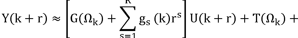
[0029] Bei LPM wird der Frequenzgang G lokal um eine lokale Frequenz k durch ein Polynom angenähert. Das wird für alle Frequenzen jcok des Frequenzganges G gemacht. Wird eine generalisierte Frequenz Qk verwendet, mit Qk = joük für den zeitkontinuierlichen Fall und Qk = e jCükfür den zeitdiskreten Fall, kann das Eingangs-Ausgangsverhalten des dynamischen Systems (Prüfaufbau PA) in der FormIn LPM, the frequency response G is locally approximated by a local frequency k by a polynomial. This is done for all frequencies jco k of frequency response G. If a generalized frequency Q k is used, with Q k = joü k for the continuous-time case and Q k = e jCük for the time-discrete case, the input-output behavior of the dynamic system (test setup PA) can be in the form
Y(k) = G(Qk)U(k) + T(Qk) + V(k) angeschrieben werden. Darin bezeichnet G(Qk) die Fouriertransformierte der Übertragungsfunktion des dynamischen Systems (also den Frequenzgang zwischen dem gewählten Eingang und Ausgang), T(Qk) einen transienten Fehler im Ausgang an der Frequenz Qk, der nicht auf die Anregung zurückzuführen ist, und V(k) das Messrauschendes Ausgangssignals. Darin sind U(k) und Y(k) die Fouriertransformierten des gemessenen Eingangssignals u(t) und Ausgangssignals y(t).Y (k) = G (Q k ) U (k) + T (Q k ) + V (k) can be written. G (Q k ) denotes the Fourier transform of the transfer function of the dynamic system (i.e. the frequency response between the selected input and output), T (Q k ) a transient error in the output at frequency Q k , which is not due to the excitation, and V (k) the measurement noise of the output signal. U (k) and Y (k) are the Fourier transforms of the measured input signal u (t) and output signal y (t).
[0030] Die von der Frequenz Qk abhängigen Größen werden durch lokale Polynome um eine lokale Frequenz Qk angenähert. Die Frequenzen um Qk werden durch die Variable r = -n, -n+1, ..., n indiziert, wobei n vorgegeben oder gewählt wird. Das führt zu[0030] The k of the frequency-dependent quantities Q k can be approximated by local polynomials a local frequency Q. The frequencies around Q k are indicated by the variable r = -n, -n + 1, ..., n, where n is specified or selected. That leads to
RR
G(^k+r) ~ G(ttk) + (k)rs G (^ k + r) ~ G (tt k ) + (k) r s
S = 1S = 1
RR
T(nk+r) «T(Hk)+^\ (k)rs T (n k + r ) «T (H k ) + ^ \ (k) r s
S = 1S = 1
5/185.18
AT 520 554 B1 2019-05-15 österreichischesAT 520 554 B1 2019-05-15 Austrian
PatentamtPatent Office
RR
X ts(k)rs + V(k + 1)X t s (k) r s + V (k + 1)
S = 1 [0031] Darin bezeichnen gs und ts die 2(R + 1) unbekannten Parameter der lokalen Polynome der Ordnung R (die gewählt oder vorgegeben wird). Damit erhält man aufgrund der r für jede Frequenz k insgesamt 2n + 1 Gleichungen für 2(R + 1) Unbekannte (gs, ts). Mit einem Parametervektor 0(k) = [G(Qk) g^k) g2(k)··· gR(k) T(Qk) tj(k) t2(k)··· tR(k)] können die 2n + 1 Gleichungen in der Matrixform Y(k) = <I>(k)0(k) geschrieben werden, mit der MatrixS = 1 Here, g s and t s denote the 2 (R + 1) unknown parameters of the local polynomials of the order R (which is selected or specified). This gives a total of 2n + 1 equations for 2 (R + 1) unknowns (g s , t s ) based on the r for each frequency k. With a parameter vector 0 (k) = [G (Q k ) g ^ k) g 2 (k) ··· g R (k) T (Q k ) tj (k) t 2 (k) ··· t R (k)] the 2n + 1 equations can be written in the matrix form Y (k) = <I> (k) 0 (k), with the matrix

rR] U(k + r) . Darin sind die sich ergebenden 2n + 1 Gleichungen für die Frequenzen k jeweils übereinander gestapelt. Der Vorteil bei dieser Methode ist, dass der transiente Anteil T(Qk) direkt mitgeschätzt werden kann und nicht durch Fensteransätze für gewisse Frequenzbereiche bestimmt werden muss, wie beispielsweise bei der Spektralanalyse.r R ] U (k + r). The resulting 2n + 1 equations for the frequencies k are stacked one above the other. The advantage of this method is that the transient component T (Q k ) can be estimated directly and does not have to be determined for certain frequency ranges by window approaches, such as in spectral analysis.
[0032] Der Parametervektor 0(k) kann dann z.B. im Sinne einer kleinsten Quadrate Approximation aus einer Parameterschätzung anhand der Gleichung 0(k) = [Φ(Χ)ΗΦ(Κ)]-1Φ(Κ)ΗΥ(Κ) geschätzt werden, wobei ,,()H“ die adjungierte Matrix (transponiert und komplex konjugiert) bezeichnet.The parameter vector 0 (k) can then, for example in the sense of a least squares approximation from a parameter estimate using the equation 0 (k) = [Φ (Χ) Η Φ (Κ)] -1 Φ (Κ) Η Υ (Κ ) are estimated, whereby “() H ” denotes the adjoint matrix (transposed and complex conjugate).
[0033] Mit dem sich ergebenden Residuum e(Qk+1) = Y(k + r) [G(Qk+1)U(k + r) + T(Qk+1)] der kleinsten Quadrate Approximation kann die Varianz des Messrauschens des Ausgangssignals mit nWith the resulting residual e (Q k + 1 ) = Y (k + r) [G (Q k + 1 ) U (k + r) + T (Q k + 1 )] the least squares approximation can the variance of the measurement noise of the output signal with n
= Σ |ecnk+1)|2 r=-n berechnet werden.= Σ | ecn k + 1 ) | 2 r = -n can be calculated.
[0034] Diese Approximation liefert dann auch direkt Schätzungen für den Frequenzgang G(Qk) und auch für die transienten Anteile T(Qk). Mit „A“ werden in weitere Folge immer Schätzungen bezeichnet. Je nachdem was als Eingangssignal U(k) und als Ausgangssignal Y(k) verwendet wird, ergeben sich natürlich unterschiedliche Frequenzgänge G(Qk).This approximation then also provides direct estimates for the frequency response G (Q k ) and also for the transient components T (Q k ). Subsequent “ A ” always refers to estimates. Depending on what is used as the input signal U (k) and as the output signal Y (k), there are of course different frequency responses G (Q k ).
[0035] Auch der Fall zusätzlich verrauschter Eingangssignale u(t) oder der Fall einer Rückkopplung des verrauschten Ausgangsignals y(t) auf den Eingang (z.B. bei einem geschlossenen Regelkreis), was ebenfalls zu einem verrauschten Eingangssignal u(t) führt, kann abgedeckt werden. Um beim Vorhandensein von Eingangsrauschen systematische Fehler in der Parameterschätzung zu vermeiden, erfolgt die Parameterschätzung in diesem Fall vorteilhafterweise am geschlossenen Regelkreis. Das ist insofern keine wesentliche Einschränkung, da technische System wie ein Prüfaufbau PA auf einem Prüfstand 1 üblicherweise in einem geschlossenen Regelkreis betrieben werden. Hierbei geht man von einem Referenzsignal s(t) (bzw. der Fouriertransformierten S(k)) aus, das der Sollwertvorgabe für geschlossenen Regelkreis entspricht. Der Zusammenhang zwischen dem Eingangssignal u(t) und dem Referenzsignal s(t) ergibt sich mit der Übertragungsfunktion R des Reglers und den aktuellen Istwerten yist zu u = (s - yist)-R. Es werden dann beispielsweise wie oben beschrieben der Frequenzgang Gru(Qk) des Referenzsignals zum Eingang U(k) und der Frequenzgang Gry(Qk) des Referenzsignals zum Ausgang Y(k) ermittelt, was zu geschätzten Frequenzgängen Gru(Qk) und Gry(Qk) führt, mit Grz(Ok) = [Gry(Qk) Gru(Ok)]T. Mit VY(k) wird das Messrauschen des Ausgangssignals Y(k) bezeichnet und mit Vu(k) das Messrauschen des Eingangssignals U(k). Mit Z(k) = [Y(k) U(k)]T und Vz(k) = [VY(k) Vu(k)]T kann die Systemgleichung dann in der Form Z(k) = Grz(Qk)R(k) + Trz(Qk) + Vz(k) geschrieben werden, worin Trz(Qk) = [Try(Qk) Tru(Qk)]T den transienten Systemfehler auf den Eingang und den Ausgang bezeichnet. Eine Schätzung des Frequenzganges G(Qk) beiThe case of additionally noisy input signals u (t) or the case of feedback of the noisy output signal y (t) to the input (for example in the case of a closed control loop), which likewise leads to a noisy input signal u (t), can be covered become. In order to avoid systematic errors in the parameter estimation in the presence of input noise, the parameter estimation in this case is advantageously carried out on the closed control loop. This is not a significant limitation, since technical systems such as a PA test setup on a test bench 1 are usually operated in a closed control loop. This is based on a reference signal s (t) (or the Fourier transform S (k)) which corresponds to the setpoint specification for a closed control loop. The relationship between the input signal u (t) and the reference signal s (t) results from the transfer function R of the controller and the current actual values y ist zu u = (s - y ist ) -R. The frequency response G ru (Q k ) of the reference signal to the input U (k) and the frequency response G ry (Q k ) of the reference signal to the output Y (k) are then determined, as described above, which leads to estimated frequency responses G ru (Q k ) and G ry (Q k ) leads, with G rz (O k ) = [G ry (Q k ) G ru (O k )] T. VY (k) denotes the measurement noise of the output signal Y (k) and Vu (k) denotes the measurement noise of the input signal U (k). With Z (k) = [Y (k) U (k)] T and Vz (k) = [V Y (k) Vu (k)] T the system equation can then be expressed in the form Z (k) = G rz ( Q k ) R (k) + T rz (Q k ) + V z (k), where T rz (Q k ) = [T ry (Q k ) T ru (Q k )] T the transient system error designated the entrance and the exit. An estimate of the frequency response G (Q k ) at
6/186.18
AT 520 554 B1 2019-05-15 österreichischesAT 520 554 B1 2019-05-15 Austrian
PatentamtPatent Office
Vorhandensein von Eingangsrauschen und Ausgangsrauschen ergibt sich dann aus G(nk) = Gry(fik)Gru(fik)· [0036] Analog zum Fall mit nur Ausgangsrauschen kann auch im Fall von Eingangsrauschen und Ausgangsrauschen eine Varianz Oy(k) des Messrauschens des Ausgangssignals, eine Varianz (k) des Messrauschens des Eingangssignals und eine Kovarianz ayu(k) des Rauschens zwischen Eingang und Ausgang ermittelt werden.The existence of input noise and output noise then results from G (n k ) = G ry ( fi k) G ru ( fi k) · Analogously to the case with only output noise, a variance Oy (k ) of the measurement noise of the output signal, a variance (k) of the measurement noise of the input signal and a covariance ayu (k) of the noise between the input and output.
[0037] Für die Anregung des dynamischen Systems wird der Drehmomentenerzeuger DE, wie der Verbrennungsmotor 2, vorzugsweise geschleppt, also nicht befeuert, betrieben. Es wäre zwar auch aktiv betriebener Drehmomentenerzeuger DE, wie ein befeuerter Verbrennungsmotor 2, bei Anregung möglich, was aber die Identifikation komplexer machen würde, weil der Drehmomentenerzeuger DE selbst Drehzahlschwingungen einbringen würde. Für die Anregung wird daher vorzugsweise die mit dem Drehmomentenerzeuger DE verbundene Drehmomentensenke DS, die Belastungsmaschine 3, die durch Ausführung als Elektromotor auch antreiben kann, verwendet und es werden zur Anregung Drehzahlschwingungen eingeprägt. Die Anregung kann mit verschiedenen Signalen, wie beispielsweise einem Multisine-Signal (bei dem in jedem Zeitpunkt gleichzeitig mehrere Frequenzen angeregt werden) oder einem Chirp-Signal (bei dem zu jedem Zeitpunkt eine Frequenz angeregt wird, beispielsweise mit linearem Frequenzanstieg) erfolgen. Das Anregesignal ist die Sollwertvorgabe für den Prüfstand 1 für den Anregebetrieb. Beispielsweise werden als Anregesignal Drehzahl-Sollwertvorgaben für den Regler der Belastungsmaschine 3 vorgegeben.For the excitation of the dynamic system, the torque generator DE, like the internal combustion engine 2, is preferably towed, ie not fired, operated. Actually operated torque generator DE, such as a fired internal combustion engine 2, would also be possible with excitation, but this would make identification more complex because the torque generator DE itself would introduce speed oscillations. For the excitation, therefore, the torque sink DS connected to the torque generator DE, the loading machine 3, which can also drive by being designed as an electric motor, is preferably used, and speed oscillations are impressed for excitation. The excitation can take place with various signals, such as, for example, a multisine signal (in which several frequencies are excited simultaneously at any time) or a chirp signal (in which a frequency is excited at any time, for example with a linear frequency increase). The pickup signal is the setpoint specification for test bench 1 for pickup operation. For example, speed setpoint specifications for the controller of the loading machine 3 are specified as the excitation signal.
[0038] Aus einem Frequenzgang G(Qk) können einige wichtige Eigenschaften des dynamischen Systems abgeleitet werden, wie anhand der Fig.2a und 2b, in denen jeweils die Amplitude A = |G(Qk)| des Frequenzgang G(Qk) dargestellt ist, beispielhaft erläutert wird. Dargestellt sind in Fig.2a der Frequenzgang G(Qk) mit dem Drehmoment TD der Belastungsmaschine 3 als Eingang u(t) und der Drehzahl ω0 der Belastungsmaschine 3 als Ausgang y(t), sowie in Fig.2b der Frequenzgang G(Qk) mit dem Drehmoment TD der Belastungsmaschine 3 als Eingang u(t) und der Drehzahl ωΕ des Verbrennungsmotors 2 als Ausgang y(t). Das bedeutet, dass bei Anregung der Eingang u(t) und der Ausgang u(t) gemessen werden und daraus wie beschrieben aus deren Fouriertransformierten U(k), Y(k) der Frequenzgang G(Qk) ermittelt wird. Dabei können natürlich verschiedene Eingangssignal / Ausgangssignal Kombinationen verwendet werden, beispielsweise je nachdem welche Messgrößen vorhanden sind.Some important properties of the dynamic system can be derived from a frequency response G (Q k ), as shown in FIGS. 2a and 2b, in each of which the amplitude A = | G (Q k ) | of the frequency response G (Q k ) is shown, is explained as an example. The frequency response G (Q k ) with the torque T D of the loading machine 3 as input u (t) and the speed ω 0 of the loading machine 3 as output y (t) are shown in FIG. 2a, and the frequency response G in FIG. 2a (Q k ) with the torque TD of the load machine 3 as the input u (t) and the speed ω Ε of the internal combustion engine 2 as the output y (t). This means that upon excitation, the input u (t) and the output u (t) are measured and, as described, the frequency response G (Q k ) is determined from their Fourier transforms U (k), Y (k). Of course, different input signal / output signal combinations can be used, for example depending on which measured variables are available.
[0039] Aus dem Frequenzgang G(Qk) können beispielsweise Resonanzfrequenzen ooR und/oder Tilgungsfrequenzen ωΕ abgeleitet werden. Beide Frequenzen können durch die Ermittlung von Minima und Maxima und der Gradienten im Frequenzgang G(Qk) ermittelt werden. Eine Tilgungsfrequenz ωτ ist demnach ein Minimum mit Gradientenumkehr von negativ auf positiv. Eine Resonanzfrequenz ooR ein Maximum mit Gradientenumkehr von positiv auf negativ. Natürlich können im Frequenzgang G(Qk) mehrere oder auch keine Tilgungsfrequenzen ωτ und/oder Resonanzfrequenzen ooR auftreten. Weiters können aus dem Frequenzgang G(Qk) auch Information zu den Nullstellen abgeleitet werden. Grundsätzlich sind charakteristische Frequenzgänge für verschiedene Systeme bekannt, beispielsweise für ein Zweimassen-Schwingsystem (Fig.2a, 2b) oder ein Mehrmassenschwinger. Durch Vergleich der bekannten Frequenzgänge mit dem ermittelten Frequenzgang G(Qk) kann auf eine bestimmte Modellstruktur geschlossen werden. Nachdem sich der Frequenzgang G(Qk) in der Form Zählerpolynom zu Nennerpolynom darstellen lässt, kann anhand dieses Vergleichs beispielsweise die Ordnung des Zähler- und Nennerpolynoms (was der Modellstruktur entspricht) festgelegt werden. Auch aus der Anzahl der Resonanzfrequenzen ωΒ können Rückschlüsse auf die Modellstruktur erfolgen. Die Anzahl der Resonanzfrequenzen ωΒ entspricht dabei üblicherweise der Anzahl der schwingfähigen Massen minus eins. Ein Zweimassenschwingsystem hat demnach eine Resonanzfrequenz coR (wie z.B. in Fig.2a, 2b).From the frequency response G (Q k ), for example, resonance frequencies oo R and / or repayment frequencies ω Ε can be derived. Both frequencies can be determined by determining minima and maxima and the gradients in the frequency response G (Q k ). A repayment frequency ω τ is therefore a minimum with a gradient reversal from negative to positive. A resonance frequency oo R a maximum with gradient reversal from positive to negative. Of course, several or no eradication frequencies ω τ and / or resonance frequencies oo R can occur in the frequency response G (Q k ). Furthermore, information on the zeros can also be derived from the frequency response G (Q k ). In principle, characteristic frequency responses for various systems are known, for example for a two-mass oscillation system (FIGS. 2a, 2b) or a multi-mass oscillator. A specific model structure can be concluded by comparing the known frequency responses with the determined frequency response G (Q k ). After the frequency response G (Q k ) can be represented in the form of numerator polynomial to denominator polynomial, the comparison of the numerator and denominator polynomial (which corresponds to the model structure) can be determined on the basis of this comparison. The number of resonance frequencies ω Β can also be used to draw conclusions about the model structure. The number of resonance frequencies ω Β usually corresponds to the number of vibratable masses minus one. A two-mass oscillation system accordingly has a resonance frequency co R (as for example in FIGS. 2a, 2b).
[0040] Für verschiedene Systemkonfigurationen (mit schwingfähigen Massen und mechanischen Kopplungen dazwischen) ergeben sich daher unterschiedliche charakteristische Frequenzgänge G(Qk), die allerdings bekannt sind. Die charakteristischen Frequenzgänge G(Qk)Different characteristic frequency responses G (Q k ) therefore result for different system configurations (with oscillating masses and mechanical couplings between them), which are, however, known. The characteristic frequency responses G (Q k )
7/187.18
AT 520 554 B1 2019-05-15 österreichischesAT 520 554 B1 2019-05-15 Austrian
Patentamt könne beispielsweise hinterlegt sein, um durch Vergleich des geschätzten FrequenzgangesPatent office can be deposited, for example, by comparing the estimated frequency response
G(Qk) auf eine Modellstruktur des vorliegenden Prüfaufbaus PA schließen zu können.G (Q k ) to be able to conclude a model structure of the present test setup PA.
[0041] In den Fig.2a und 2b sind außerdem auch die jeweiligen ermittelten Kovarianzen ayu(k) dargestellt.2a and 2b also show the respective determined covariances ayu (k).
[0042] Der Vorteil bei diesem Vorgehen ist auch darin zu sehen, dass man für die nichtparametrische Identifikation unter Umständen auch ohne einer Messung eines Drehmoments am Prüfstand 1 auskommen kann, beispielsweise zur Auswahl einer Modellstruktur. Das ermöglicht auf einfache Weise, insbesondere ohne Aufnahme eines Drehmomentenmessflansches in den Prüfaufbau PA, eine erste Abschätzung des dynamischen Verhaltens des Prüfaufbaus PA am Prüfstand 1.The advantage of this procedure can also be seen in the fact that for non-parametric identification it is possible, under certain circumstances, to do without measuring a torque on the test bench 1, for example for selecting a model structure. This enables a first estimate of the dynamic behavior of the test setup PA on the test bench 1 in a simple manner, in particular without including a torque measuring flange in the test setup PA.
[0043] Auf die nicht-parametrische Identifikationsmethode folgt erfindungsgemäß eine parametrische Identifikationsmethode, mit der das dynamische Eingangs-Ausgangsverhalten des dynamischen technischen Systems (Prüfaufbau PA) mit einem Modell mit Systemparametern SP, die das dynamische Verhalten des Prüfaufbaus PA beschreiben, angenähert wird. Auch hierfür gibt es bekannte Methoden, sowohl im Zeitbereich, als auch im Frequenzbereich, die nachfolgend kurz erläutert werden.The non-parametric identification method according to the invention is followed by a parametric identification method with which the dynamic input-output behavior of the dynamic technical system (test setup PA) is approximated with a model with system parameters SP that describe the dynamic behavior of the test setup PA. There are also known methods for this, both in the time domain and in the frequency domain, which are briefly explained below.
[0044] Die parametrische Identifikation basiert auf einem Modell des dynamischen Systems mit den Modellparametern Θ, das den Ausgang y(k) aus dem Eingang u(k) und einer Störung berechnet. Die Abbildung des Eingangs u(k) auf den Ausgang y(k) erfolgt mit einem Streckenmoinf dell G(q, θ) = £geq_k, mit Streckenmodellparametern ge und den Rückwärtsverschiebeoperator k=l q k. Eine Störung (z.B. durch Messrauschen) kann dabei mit einem Störmodell H(q, Θ) und einer Wahrscheinlichkeitsverteilung e, oder eine Wahrscheinlichkeitsdichtefunktion fe, modelliert inf werden, mit H(q, θ) = 1 + £heq_k und Rauschmodellparametern he. Zu beachten ist hier, dass k=l k darin keine Frequenz bezeichnet wie bei der nicht-parametrischen Identifikation, sondern einen Zeitindex der zeitdiskreten Signale, z.B. u(k) und y(k). Das Modell des dynamischen Systems kann dann in einer zeitdiskreten Notation als y(k) = G(q,9)u(k) + H(q,9)e(k) angeschrieben werden. Das Ziel ist folglich, mit diesem Modell den Ausgang y(k) zum Zeitpunkt k aus bekannten, vergangenen Daten des Eingangs u und des Ausgangs y bis zum Zeitpunkt k-1 (also vergangene Daten) zu schätzen. Zur Verfügung stehen die Daten ZK = {u(1), y(1), ..., u(k1), y(k-1), u(k), y(k)}. Hierfür gibt es verschiedene bekannte Ansätze.The parametric identification is based on a model of the dynamic system with the model parameters Θ, which calculates the output y (k) from the input u (k) and a fault. The mapping of the input u (k) to the output y (k) is carried out with a link moinf dell G (q, θ) = £ g e q _k , with link model parameters g e and the backward shift operator k = lq k . A disturbance (e.g. due to measurement noise) can be modeled with a disturbance model H (q, Θ) and a probability distribution e, or a probability density function f e , with H (q, θ) = 1 + £ h e q _k and noise model parameters h e . It should be noted here that k = lk does not denote a frequency as in non-parametric identification, but rather a time index of the discrete-time signals, e.g. u (k) and y (k). The model of the dynamic system can then be written in a discrete-time notation as y (k) = G (q, 9) u (k) + H (q, 9) e (k). The goal is therefore to use this model to estimate the output y (k) at the time k from known past data of the input u and the output y up to the time k-1 (ie past data). The data Z K = {u (1), y (1), ..., u (k1), y (k-1), u (k), y (k)} are available. There are various known approaches for this.
[0045] Ein Beispiel für eine parametrische Identifikationsmethode im Zeitbereich ist die sogenannte Prediction Error Method (PEM), wie beispielsweise in L. Ljung, „System Identification: Theoryforthe User“, 2nd Edition Prentice Hall PTR, 1999 beschrieben. Eine bekannte Methode im Frequenzbereich ist die Maximum Likelihood Estimator Method (MLE).An example of a parametric identification method in the time domain is the so-called Prediction Error Method (PEM), as described for example in L. Ljung, "System Identification: Theoryforthe User", 2nd Edition Prentice Hall PTR, 1999. A known method in the frequency domain is the Maximum Likelihood Estimator Method (MLE).
[0046] Bei PEM geht man vom Modell des dynamischen Systems y(k) = G(q, 9)u(k) + H(q, 9)e(k) aus, worin 9 die Modellparameter sind. Darin bezeichnet v(k) farbiges Rauschen.PEM is based on the model of the dynamic system y (k) = G (q, 9) u (k) + H (q, 9) e (k), where 9 are the model parameters. Here v (k) denotes colored noise.
v(k)v (k)
Wird als Wahrscheinlichkeitsverteilung e(k) weißes Rauchen verwendet, dann kann das farbige COIf white smoking is used as the probability distribution e (k), the colored CO
Rauschen v(k) auch als v(k) = H(q,9)e(k) = £h(t)e(k-t) = e(k) + m(k- 1) angeschrieben t=0 werden. Darin ist m(k-1) der Mittelwert bis zum Zeitpunkt (k-1). Das kann noch in der Form m(k1) = v(k | k-1) = (H(q,9)-1 )e(k) = (1-Hinv(q,9))v(k) umgeschrieben werden, mit der Inversen Hinv von H. Die Schätzung des Ausgangs y(k | k-1) aus den Daten ZK kann dann in der folgenden Form angeschrieben werden:Noise v (k) can also be written as v (k) = H (q, 9) e (k) = £ h (t) e (kt) = e (k) + m (k- 1) t = 0. Here m (k-1) is the mean up to time (k-1). This can be done in the form m (k1) = v (k | k-1) = (H (q, 9) -1) e (k) = (1-H inv (q, 9)) v (k) can be rewritten with the inverse H inv of H. The estimate of the output y (k | k-1) from the data Z K can then be written in the following form:
[0047] y(k I 9, ZK) = G(q,9)u(k)+v(k | k -1) = Hinv (q, 9)G(q,9)u(k)+(1-Hinv (q, 9))y(k).Y (k I 9, Z K ) = G (q, 9) u (k) + v (k | k -1) = H inv (q, 9) G (q, 9) u (k) + (1-H inv (q, 9)) y (k).
[0048] Der Schätzfehler ergibt sich dann zu c(k,9) = y(k) - y(k,9). Um die Modellparameter 9 zu ermitteln kann eine Kostenfunktion J(9, ZK) angeschrieben werden, die den gewichteten Schätzfehler minimiert. Dazu kann beispielsweise eine mathematische Norm l(), z.B. die EuklidischeThe estimation error then results in c (k, 9) = y (k) - y (k, 9). In order to determine the model parameters 9, a cost function J (9, Z K ) can be written which minimizes the weighted estimation error. A mathematical norm l (), for example the Euclidean, can be used for this purpose
8/188.18
AT 520 554 B1 2019-05-15 österreichischesAT 520 554 B1 2019-05-15 Austrian
PatentamtPatent Office
Norm (2-Norm) 1() = ||()||2, des gewichteten Schätzfehlers verwendet werden. Bezeichnet cF(k,0) = F(q)c(k,0) den gewichteten Schätzfehler mit den Gewichten F(q), dann kann die KosK-l tenfunktion beispielsweise als J(9, ZK) = £ l(sF(k, θ)) angeschrieben werden. Diese Kostenk=0 funktion J wird minimiert, um die Modellparameter 9 zu schätzen: θ = argmin J(9, ZK).Norm (2 norm) 1 () = || () || 2 , the weighted estimation error can be used. If c F (k, 0) = F (q) c (k, 0) denotes the weighted estimation error with the weights F (q), then the KosK-l ten function can for example be as J (9, Z K ) = £ l ( s F (k, θ)) can be written. This cost k = 0 function J is minimized in order to estimate the model parameters 9: θ = argmin J (9, Z K ).
e [0049] Um aus den Modellparametern 9 die gesuchten Systemparameter SP des dynamischen Systems zu bestimmen, kann das zeitdiskrete Modell y(k) = G(q,0)u(k) + H(q,9)e(k) in einer vorteilhaften praktischen Implementierung mit Polynomen A(q) = 1 + a^-i-... + anaq na, B(q) = 1 + biq 1 + ... + bnbq'nb und C(q) = 1 + Ciq_1 + ... + cncq'nc auch in der Form y(k) =^u(k) +e To determine the sought system parameters SP of the dynamic system from the model parameters 9, the discrete-time model y (k) = G (q, 0) u (k) + H (q, 9) e (k) in an advantageous practical implementation with polynomials A (q) = 1 + a ^ -i -... + a na q na , B (q) = 1 + biq 1 + ... + bnbq ' nb and C (q) = 1 + Ciq _1 + ... + c nc q ' nc also in the form y (k) = ^ u (k) +
A(.q) g-' ^ye(k) (ARMAX Modell) angeschrieben werden. Die Modellparameter 9 ergeben sich dann zu = [ai ... ana bi ... bnb Ci ... cnc ] Im Falle von weißen Rauschen e(k) reduziert sich das auf y(k) = ^u(k) +—!—e(k) (ARX Modell) mit 0 = [aj ... ana bj ... bnb]. Die Ordnung na,A (.q) g - '^ ye (k) (ARMAX model). The model parameters 9 then result in = [ai ... a na bi ... b n b Ci ... c nc ] In the case of white noise e (k) this is reduced to y (k) = ^ u ( k) + -! - e (k) (ARX model) with 0 = [aj ... a na bj ... b nb ]. The order n a ,
A(q) A(q)A (q) A (q)
TT nb, nc der Polynome A, B, C ist gemäß der mit der nicht-parametrischen Identifikation festgelegten Modellstruktur vorgegeben.TT n b , n c of the polynomials A, B, C is specified in accordance with the model structure defined with the non-parametric identification.
[0050] Bei einem Zweimassenschwinger, wie beispielsweise bei einem Prüfaufbau nach Fig.1, ergibt sich als Nennerpolynom A(q) ein Polynom mit Ordnung na=2 und als Zählerpolynom B(q) ein Polynom mit Ordnung nb=1.In a dual-mass oscillator, such as in a test setup according to FIG. 1, the denominator polynomial A (q) is a polynomial with order n a = 2 and the numerator polynomial B (q) is a polynomial with order n b = 1.
[0051] Um auf die gesuchten Systemparameter SP zu kommen, wird von einer Äquivalenz der Modellparameter im zeitdiskreten Modell und den Parametern eines physikalischen Modells des dynamischen Systems ausgegangen.In order to arrive at the sought system parameters SP, an equivalence of the model parameters in the discrete-time model and the parameters of a physical model of the dynamic system is assumed.
[0052] Beispielsweise kann der Prüfaufbau PA nach Fig.1 mit Verbrennungsmotor 2 (mit Massenträgheit JE), Prüfstandwelle 4 (mit Drehsteifigkeit c und Drehdämpfung d) und Belastungsmaschine 3 (mit Massenträgheitsmoment JD) physikalisch gemäß ω0 1 JEs2 + ds + c td s JeJds2 + d(JE + Jd)s + cCJe + Jd) ωΕ 1 ds + cFor example, the test setup PA according to FIG. 1 with the internal combustion engine 2 (with inertia J E ), test stand shaft 4 (with torsional rigidity c and torsional damping d) and load machine 3 (with moment of inertia J D ) physically according to ω 0 1 J E s 2 + ds + c t d s JeJd s2 + d (J E + Jd) s + c CJe + Jd) ω Ε 1 ds + c
Td s JeJds2 + JCJe + Jd)s + c(Je + Jd) modelliert werden. Ein anderes Beispiel ergibt sich beim Zweimassenschwinger der Fig.1 mit dem Eingangssignal ω0 und dem Ausgangssignal ωΕ, was zu einem Modell , c.+d,s— führt.Td s JeJd s2 + JCJe + Jd) s + c (Je + Jd) can be modeled. Another example arises in the dual-mass oscillator of FIG. 1 with the input signal ω 0 and the output signal ω Ε , which results in a model, c . + d , s - leads.
Tp JEsz+ds+cTp J E s z + ds + c
In diesem Fall wäre natürlich auch der Frequenzgang G mit diesem Eingangssignal und Ausgangssignal ermittelt worden. Darin erkennt man auch, dass sich bei verschiedenen Eingangsund/oder Ausgangssignalen auch verschiedene Modelle ergeben. Diese Gleichungen können in eine zeitdiskrete Notation gebracht werden, was einen Vergleich der Systemparameter SP (JE, c, d, JD) mit den geschätzten Modellparametern θ = [ai ... ana bi ... bnb] ermöglicht. Daraus können die Systemparameter SP (JE, c, d, JD) ermittelt werden.In this case, the frequency response G would of course also have been determined with this input signal and output signal. This also shows that different models result from different input and / or output signals. These equations can be put into a discrete-time notation, which enables a comparison of the system parameters SP (J E , c, d, J D ) with the estimated model parameters θ = [ai ... a na bi ... b n b]. The system parameters SP (J E , c, d, J D ) can be determined from this.
[0053] Nachdem die Modellstruktur aus dem Frequenzgang G bekannt ist, kann das Modell auch in Teilmodelle unterteilt werden, was die Ermittlung der Systemparameter SP (JE, c, d, JD) erleichtert. Ein Zweimasseschwinger kann beispielsweise in ein erstes Teilmodell für den Verbrennungsmotor 2, ein zweites Teilmodell für die Prüfstandwelle 4 und ein drittes Teilmodell für die Belastungsmaschine 3 unterteilt werden. Damit kann auch das zeitdiskrete Modell in entsprechende Teilmodelle unterteilt werden, womit sich die Ordnungen der Teilmodelle entsprechend reduziert. Die Modellparameter der Teilmodelle werden dann wie oben beschrieben geschätzt.After the model structure is known from the frequency response G, the model can also be divided into sub-models, which facilitates the determination of the system parameters SP (J E , c, d, J D ). A two-mass oscillator can be subdivided, for example, into a first sub-model for the internal combustion engine 2, a second sub-model for the test bench shaft 4 and a third sub-model for the load machine 3. The discrete-time model can thus also be subdivided into corresponding sub-models, which reduces the order of the sub-models accordingly. The model parameters of the sub-models are then estimated as described above.
[0054] In gleicher Weise werden dann physikalische Teilmodelle verwendet, was nachfolgendIn the same way, physical sub-models are then used, which follows
9/189.18
AT 520 554 B1 2019-05-15 österreichischesAT 520 554 B1 2019-05-15 Austrian
Patentamt wieder am Beispiel des Zweimassenschwingers beschrieben wird.Patent office is again described using the example of the dual mass transducer.
[0055] Für das erste Teilmodell wird das Momentengleichgewicht für den Verbrennungsmotor 2 (Fig.1) in zeitkontinuierlicher Notation in der Form ωΕ = — (TE(s)- Tsh(s)) angeschrieben, mitFor the first sub-model, the torque balance for the internal combustion engine 2 (FIG. 1) is written in continuous-time notation in the form ω Ε = - (T E (s) - T sh ( s )), with
Jes v j dem Laplace-Operator s, der Drehzahl ωΕ des Verbrennungsmotors 2, dem inneren Drehmoment TE des Verbrennungsmotors 2 und dem Wellenmoment Tsh. Nachdem der Verbrennungsmotor 2 vorzugsweise geschleppt betrieben wird, ergibt sich im nichtstochastischen Teil der Modellstruktur TE=0 und folglich ωΕ = -r-Tsh(s) oder coE(k) - coE(k- 1) = 7^Tsh(k) in zeitdisJes Je kreter Notation mit der bekannten Abtastzeit Ts (typischerweise im kHz-Bereich). Durch Vergleich erhält man dann unmittelbar aus dem ersten Teilmodell ai=-1 und bi=Ts/JE, woraus der Systemparameter JE ermittelt werden kann. Das ermöglicht auch eine Abschätzung der Güte der Parameterschätzung. Wenn der geschätzte Modellparameter aj nahe eins liegt, dann kann von einer hohen Identifikationsgüte ausgegangen werden.Each svj is the Laplace operator s, the speed ω Ε of the internal combustion engine 2, the internal torque T E of the internal combustion engine 2 and the shaft torque T sh . After the internal combustion engine 2 is preferably operated in a towed manner, the non-stochastic part of the model structure results in T E = 0 and consequently ω Ε = -rT sh (s) or co E (k) - co E (k-1) = 7 ^ T sh (k) in time disJe s per creter notation with the known sampling time Ts (typically in the kHz range). By comparison, one then directly obtains ai = -1 and bi = Ts / J E from the first partial model, from which the system parameter J E can be determined. This also enables the quality of the parameter estimation to be estimated. If the estimated model parameter aj is close to one, a high quality of identification can be assumed.
[0056] Um die Systemparameter SP der Kopplung zwischen Verbrennungsmotor 2 und Belastungsmaschine 3, Drehdämpfung d und Drehsteifigkeit c, zu bestimmen, wird das zweite Teilmodell für die Prüfstandwelle 4 herangezogen. Ausgehend vom Drehmomentengleichgewicht an der freigeschnittenen Prüfstandwelle 4 kann mit einem Δω = ωΕ - ω0, mit der Drehzahl ω0 der Belastungsmaschine 3 und wieder mit der Annahme TE=0 angeschrieben werden Tsh(s) = (-; + ά)Δω(» oder in zeitdiskreter Notation Tsh(k)-Tsh(k-1)=(-cTs+d)Aco(k)-dAcü(k-1). Durch Vergleich ergeben sich aus den Modellparameter des zweiten Teilmodells wieder die Systemparameter a! = -1, bj = -(cTs + d) und b2 = -d, woraus die gesuchten Systemparameter c, d wieder bestimmt werden können. Die Modellparameter ai, bi des zweiten Teilmodells entsprechen dabei natürlich nicht den Modellparametern des ersten Teilmodells.In order to determine the system parameters SP of the coupling between the internal combustion engine 2 and the load machine 3, torsional damping d and torsional rigidity c, the second partial model for the test bench shaft 4 is used. Starting from the torque equilibrium on the cut-out test stand shaft 4, the load machine 3 can be written with a Δω = ω Ε - ω 0 , with the speed ω 0 and again with the assumption T E = 0 T sh (s) = (-; + ά) Δω (»or in time-discrete notation T sh (k) -T sh (k-1) = (- cTs + d) Aco (k) -dAcü (k-1). By comparison, the model parameters of the second partial model again result the system parameters a! = -1, bj = - (cTs + d) and b 2 = -d, from which the sought system parameters c, d can be determined again, of course, the model parameters ai, bi of the second partial model do not correspond to the model parameters of first partial model.
[0057] In gleicher Weise kann ein drittes Teilmodell für die Belastungsmaschine 3 verwendet werden, um den Systemparameter JD zu ermitteln. Die Massenträgheit JD der Belastungsmaschine kann für den Zweimassenschwinger natürlich auch aus der Resonanzfrequenz die aus der nicht-parametrischen Identifikation bekannt ist, ermittelt werden, beispielsweise als JD = 2 C c- Oftmals ist die Massenträgheit JD der Belastungsmaschine 3 bekannt, sodass mit der “R Je bekannten Massenträgheit auch ein Abgleich der Identifikationsgüte erfolgen kann.In the same way, a third sub-model can be used for the loading machine 3 in order to determine the system parameter J D. The inertia J D of the loading machine can of course also be determined for the dual-mass oscillator from the resonance frequency that is known from the non-parametric identification, for example as J D = 2 C c - the inertia J D of the loading machine 3 is often known, so that with the “ R Depending on the known inertia, the quality of identification can also be compared.
[0058] Wie bereits erwähnt kann die parametrische Identifikation auch im Frequenzbereich erfolgen, beispielsweise mittels MLE. Bei MLE werden die Modellparameter Θ geschätzt, die die sogenannte Likelihood-Funktion maximieren. Dieses an sich bekannte Verfahren wird nachfolgend kurz erläutert.As already mentioned, the parametric identification can also take place in the frequency domain, for example by means of MLE. At MLE, the model parameters Θ are estimated that maximize the so-called likelihood function. This known method is briefly explained below.
[0059] MLE nutzt die Messdaten des Ausgangssignals y= y1; y2, ..., yN und eine zugehörige, als bekannt vorausgesetzte, Wahrscheinlichkeitsdichtefunktion fny des Messrauschens am Ausgang, die durch die Modellparameter 0 beschrieben wird. f(y|90) beschreibt die Wahrscheinlichkeitsverteilungsfunktion der vom Zufall abhängigen Teile des Schätzproblems. Mit einem hypothetischen Modell y0= G(u0, 9), das die Anregungen und die Parameter beschreibt, kann die Likelihood Funktion im Falle Messrauschen am Ausgang als f(y|0,u0) = fny(y-y0) angeschrieben werden. Darin bezeichnet uoden unverrauschten Eingang. Die unbekannten Modellparameter θ können dann durch Maximieren der Likelihood Funktion f ermittelt werden: θ(Ν) = argmax eMLE uses the measurement data of the output signal y = y 1; y 2 , ..., y N and an associated probability density function f ny of the measurement noise at the output, which is assumed to be known and which is described by the model parameters 0. f (y | 9 0 ) describes the probability distribution function of the randomly dependent parts of the estimation problem. With a hypothetical model y 0 = G (u 0 , 9) that describes the excitations and the parameters, the likelihood function in the case of measurement noise at the output can be written as f (y | 0, u 0 ) = f ny (yy 0 ) become. Designated therein u o the noiseless input. The unknown model parameters θ can then be determined by maximizing the likelihood function f: θ (Ν) = argmax e
f(y I 0,uo).f (y I 0, uo).
[0060] Im Falle zusätzlichen Messrauschens am Eingang kann die Likelihood Funktion als f(y,u I 9,y0,u0) = fny (y - yo)fnu(u -u0) angeschrieben werde, mit der Wahrscheinlichkeitsdichtefunktion fnu des Messrauschens am Eingang.In the case of additional measurement noise at the input, the likelihood function can be written as f (y, u I 9, y 0 , u 0 ) = f ny (y - yo) f nu (u -u 0 ), with the probability density function f nu of measurement noise at the entrance.
[0061] Unter der Annahme, dass das Rauschen am Eingang und am Ausgang Mittelwert Null haben, normalverteilt sind und unabhängige von den Frequenzen sind, kann eine Gauß'scheAssuming that the noise at the input and at the output have zero mean, are normally distributed and are independent of the frequencies, a Gaussian
10/1810/18
AT 520 554 B1 2019-05-15 österreichischesAT 520 554 B1 2019-05-15 Austrian
PatentamtPatent Office
Kostenfunktion VML(0,Z) = £ Ιθ^θί2^ (Likelihood Funktion f) angeschrieben werden. Darin k=l ist Θ der Parametervektor und Z(k) = [Y(k) U(k)] bezeichnet die vorliegenden Messdaten des Eingangs U(k) und des Ausgangs Y(k). e bezeichnet einen Fehler über alle Frequenzen Qkder Form e(Qk,9,Z(k)) = Y(k) - G(Qk, 9)U(k) und σθ die Kovarianz des Fehlers e in der Form o|(nk, Θ) = Oy(k) -I- |G(fik, 9)|2au(k) - 2Re (ϋζΩ^σγυ^)}. Re bezeichnet hierbei den Realteil.Cost function V ML (0, Z) = £ Ιθ ^ θί 2 ^ (likelihood function f) can be written on. Therein k = l is Θ the parameter vector and Z (k) = [Y (k) U (k)] denotes the available measurement data of the input U (k) and the output Y (k). e denotes an error over all frequencies Q k of the form e (Q k , 9, Z (k)) = Y (k) - G (Q k , 9) U (k) and σθ the covariance of the error e in the form o | (n k , Θ) = Oy (k) -I- | G (fi k , 9) | 2 au (k) - 2Re (ϋζΩ ^ σγυ ^)}. Re denotes the real part.
[0062] Wie zu erkennen ist, werden für die obigen Gleichungen die Varianzen und die Kovarianz des Messrauschens am Eingang a^(k), Ausgang oy(k) und Eingang-Ausgang ayu(k) benötigt. Diese können vorteilhafterweise aus der nicht-parametrischen Identifikation wie oben beschrieben erhalten werden.As can be seen, the variances and the covariance of the measurement noise at the input a ^ (k), output oy (k) and input-output ayu (k) are required for the above equations. These can advantageously be obtained from the non-parametric identification as described above.
[0063] Nachdem das sich ergebende Optimierungsproblem der Maximierung der Kostenfunktion VMl (Likelihood Funktion) nichtlinear ist, wird die Optimierung beispielsweise mit der bekannten Levenberg-Marquardt Methode gelöst. Die Konvergenz der Optimalität der Optimierung hängt wesentlich von den Anfangswerten der Optimierung ab. Als Anfangswerte können Schätzwerte der gesuchten Systemparameter SP herangezogen werden oder es können andere bekannte Initialisierungsverfahren, beispielsweise aus einem Generalized Total Least Square Verfahren, angewendet werden.[0063] After the resulting optimization problem is non-linear to maximize the cost function V M l (likelihood function), the optimization is achieved for example with the well-known Levenberg-Marquardt method. The convergence of the optimality of the optimization essentially depends on the initial values of the optimization. Estimated values of the sought system parameters SP can be used as initial values or other known initialization methods, for example from a generalized total least square method, can be used.
[0064] Wird eine parametrische Übertragungsfunktion G(nk, θ) = verwendet, kann die Kostenfunktion für MLE zu w 1V |Ae(nk)Y(k) - Βθ(Ω0Υ(Κ)|2 If a parametric transfer function G (n k , θ) = is used, the cost function for MLE can be w 1V | A e (n k ) Y (k) - Βθ (Ω0Υ (Κ) | 2
VmlwA) — ö / ~:---------------TT--------ξ----\ Fö|(k)|Αθ(Ω0|23u(k)|Βθ(Ω012 - 2 Re (a£u(k)Ae(Ok)Be(Ok)) umgeschrieben werden. Darin sind A und B wieder Polynome A(q) = 1 + aiq_1 +... + anaq'na, B(q) = 1 + b!q1 +... + bnbq nb. Die Ordnung na, nb der Polynome ergibt sich wieder aus dem mit der nicht-parametrischen Identifikation geschätzten Frequenzgang G(Qk). Man erhält damit aus der Optimierung wieder die Modellparameter 0=[a! ... ana bj ... bnb], die wiederum aus einem Vergleich mit einem physikalischen Modell des dynamischen Systems (Prüfaufbau PA) verglichen werden, um auf die Systemparameter SP (JE, c, d, JD) zu kommen. In gleicher Weise können auch wieder Teilmodelle verwendet werden, um die Ermittlung der Systemparameter SP (JE, c, d, JD) zu vereinfachen.VmlwA) - ö / ~: --------------- TT -------- ξ ---- \ F ö | (k) | Αθ (Ω0 | 2 3u (k) | Βθ (Ω01 2 - 2 Re (a £ u (k) Ae (Ok) Be (Ok)), where A and B are again polynomials A (q) = 1 + aiq _1 + ... + anaq ' na , B (q) = 1 + b! q 1 + ... + bnbq nb . The order na, n b of the polynomials again results from the frequency response G (Q k ) estimated with the non-parametric identification The optimization then again results in the model parameters 0 = [a! ... a na bj ... b nb ], which in turn are compared from a comparison with a physical model of the dynamic system (test setup PA) in order to determine the System parameters SP (J E , c, d, J D ) In the same way, partial models can be used again to simplify the determination of the system parameters SP (J E , c, d, J D ).
[0065] Die Teilmodelle für den Verbrennungsmotor 2 und die Prüfstandwelle 4 in zeitdiskreter TsThe partial models for the internal combustion engine 2 and the test bench shaft 4 in time-discrete Ts
Notation mit der z-Transformation ergeben sich zu coE(k) = - Tsh(k) und Tsh(s) = (ά~^ζ-ιάΖ Aco(k), woraus sich die Systemparameter SP (JE, c, d, JD) aus den geschätzten Teilmodellen zu JE = ^,JD = 2C c ,c = (b2J~bl),d = -bs ergeben.Notation with the z transformation results in co E (k) = - T sh (k) and T sh (s) = (ά ~ ^ ζ-ι άΖ Aco (k), from which the system parameters SP (JE, c , d, JD) from the estimated partial models for JE = ^, JD = 2 C c, c = (b2 J ~ bl) , d = -b s .
bl “R_j^ Ts [0066] Die parametrische Identifikation liefert somit die Systemparameter SP (JE, c, d, JD im Falle des Zweimasseschwingers) des angeregten dynamischen Systems (der Prüfaufbau PA wie z.B. in Fig. 1 dargestellt). Mit zumindest einen Systemparameter SP, kann nun beispielsweise mit herkömmlichen Reglerentwurfsmethoden ein Regler für bestimmte Komponenten des Prüfaufbaus entworfen werden, z.B. ein Drehzahlregler für die Belastungsmaschine 3 oder ein Drehmomentenregler für den Verbrennungsmotor 2. b 1 “ R_ j ^ Ts [0066] The parametric identification thus supplies the system parameters SP (J E , c, d, J D in the case of the two-mass oscillator) of the excited dynamic system (the test setup PA as shown, for example, in FIG. 1). With at least one system parameter SP, a controller for certain components of the test setup can now be designed using conventional controller design methods, for example, a speed controller for the load machine 3 or a torque controller for the internal combustion engine 2.
[0067] In Fig.3 ist ein beispielhafter geschlossener Regelkreis für den Prüfaufbau PA nach Fig. 1 dargestellt. Die Regelstrecke 10 repräsentiert den Prüfaufbau PA mit den Massenträgheitsmomenten JE des Verbrennungsmotors 2 und JD der Belastungsmaschine 3. Die Prüfstandwelle 4 wird durch die Drehsteifigkeit c und Drehdämpfung d repräsentiert. Diese Systemparameter SP wurden durch die obige nicht-parametrische / parametrische Identifikation ermittelt. Die Belastungsmaschine 3 wird durch einen Dynoregler RD (z.B. ein PI-Regler) drehzahlgeregelt. Dazu /183 shows an exemplary closed control loop for the test setup PA according to FIG. 1. The controlled system 10 represents the test setup PA with the mass moments of inertia J E of the internal combustion engine 2 and J D of the load machine 3. The test stand shaft 4 is represented by the torsional rigidity c and torsional damping d. These system parameters SP were determined by the above non-parametric / parametric identification. The loading machine 3 is speed-controlled by a Dyno controller RD (for example a PI controller). In addition / 18
AT 520 554 B1 2019-05-15 österreichischesAT 520 554 B1 2019-05-15 Austrian
Patentamt wird eine Soll-Drehzahl ωθ50ιι vorgegeben. Die sich einstellende Ist- Drehzahl ω0 wird am Prüfstand 1 gemessen. Der Regelfehler ωθ50ιι - ω0 wird durch den Dynoregler RD nach dem festgelegten Reglerverhalten ausgeregelt. Die Reglerparameter zur Einstellung des gewünschtenThe patent office specifies a target speed ω θ50 ιι. The actual speed ω 0 that occurs is measured on test bench 1. The control error ω θ50 ιι - ω 0 is corrected by the Dyno controller R D according to the specified controller behavior. The controller parameters for setting the desired
Regelverhaltens am konkreten dynamischen System können dabei mit einer hinlänglich bekannten Reglerentwurfsmethode festgelegt werden.Control behavior on the specific dynamic system can be determined using a well-known controller design method.
[0068] Die mit der nicht-parametrischen Identifikation ermittelte Resonanzfrequenz(en) coR, die ebenfalls einen Systemparameter SP darstellen,kann auch verwendet werden, um ein Filter F zu entwerfen, dass mögliche Resonanzen am Prüfstand 1 unterbinden soll. Das Ziel des Filters F ist es eine Anregung mit Resonanzfrequenz coR zu unterbinden. Um das dynamische Verhalten des Prüfaufbaus PA auf einem Prüfstand 1 mit einem Filter F möglichst geringfügig zu beeinflussen, bieten sich hierfür Filter F an, die Frequenzen innerhalb eines engen Frequenzbereiches ausfiltern, beispielsweise sogenannte Kerbfilter (Notch Filter). Dazu wird das Kerbfilter so entworfen, dass Frequenzen in einem engen Frequenzbereich um die Resonanzfrequenz coR ausgefiltert werden. Ein solches Filter F kann vor einem Regler R für eine Komponente des Prüfaufbaus PA, beispielsweise dem Dynoregler RD, zum Filtern der dem Regel R zugeführten Regelungsabweichung w (Differenz aus Sollwert SW und Istwert IW der Regelgröße) eingesetzt werden (wie in Fig.4), oder auch zum Filtern der Sollwerte SW (z.B. eine Solldrehzahl (jüdsoii) für den Regler R (wie in Fig.4 strichliert angedeutet).The resonance frequency (s) co R determined with the non-parametric identification, which also represent a system parameter SP, can also be used to design a filter F that should prevent possible resonances on the test bench 1. The aim of the filter F is to prevent excitation with a resonance frequency co R. In order to influence the dynamic behavior of the test setup PA on a test bench 1 with a filter F as little as possible, filters F are suitable for this purpose, which filter out frequencies within a narrow frequency range, for example so-called notch filters. For this purpose, the notch filter is designed so that frequencies in a narrow frequency range around the resonance frequency co R are filtered out. Such a filter F can be used in front of a controller R for a component of the test setup PA, for example the dyno controller R D , for filtering the control deviation w supplied to the control R (difference between the setpoint value SW and the actual value IW of the control variable) (as in FIG. 4 ), or for filtering the setpoints SW (eg a setpoint speed (jewsoii) for the controller R (as indicated by the broken line in Fig. 4).
[0069] Die identifizierten Systemparameter SP (ωΒ, JE, c, d, JD), oder zumindest einer davon, können aber auch für einen Beobachter verwendet werden, um nicht messbare Größen des Prüfaufbaus, beispielsweise ein inneres effektives Drehmoment TE des Verbrennungsmotors 2, zu schätzen.The identified system parameters SP (ω Β , J E , c, d, J D ), or at least one of them, can also be used for an observer to measure non-measurable quantities of the test set-up, for example an internal effective torque T E of the internal combustion engine 2.
[0070] Ebenso können die identifizierten Systemparameter SP (a>R, JE, c, d, JD), oder zumindest einer davon, verwendet werden, um Änderungen am Prüfaufbau PA, beispielsweise aufgrund Alterung, Beschädigung, Konfigurationsänderung, usw., festzustellen. Hierfür können die Systemparameter SP (JE, c, d, JD) in regelmäßigen Abständen neu ermittelt werden und die zeitliche Veränderung der Systemparameter SP (JE, c, d, JD) überwacht werden. Dabei kann der Prüflauf adaptiert werden oder unterbrochen werden, wenn es eine ungewöhnliche oder unerwünschte Änderung festgestellt wird.Likewise, the identified system parameters SP (a> R , J E , c, d, J D ), or at least one of them, can be used to make changes to the test setup PA, for example due to aging, damage, configuration changes, etc., determine. For this purpose, the system parameters SP (J E , c, d, J D ) can be newly determined at regular intervals and the change over time of the system parameters SP (J E , c, d, J D ) can be monitored. The test run can be adapted or interrupted if an unusual or undesired change is detected.
[0071] Nicht zuletzt kann auch der Prüfaufbau PA zur Durchführung des Prüfversuchs selbst verändert werden, um den zumindest einen identifizierten Systemparameter SP zu ändern, um ein gewünschtes dynamisches Verhalten am Prüfstand 1 abzubilden. Das kann beispielsweise verwendet werden, um die Dynamik des Prüfaufbaus PA am Prüfstand 1 an die Dynamik eines Fahrzeugs anzupassen, in dem der Drehmomentenerzeuger DE des Prüfaufbaus PA eingesetzt werden soll.Last but not least, the test setup PA for carrying out the test test itself can also be changed in order to change the at least one identified system parameter SP in order to map a desired dynamic behavior on the test bench 1. This can be used, for example, to adapt the dynamics of the test setup PA on the test bench 1 to the dynamics of a vehicle in which the torque generator DE of the test setup PA is to be used.
[0072] In Fig.6 ist ein Prüfstand 1 mit einem Prüfaufbau PA, beispielsweise mit einem Zweimassenschwinger wie in Fig.1, angedeutet. Am Prüfaufbau PA werden mit geeigneten Messsensoren MS Messwerte MW für die benötigten Eingangssignale u(t) und Ausgangssignale y(t) bei dynamischer Anregung erfasst, was natürlich auch die zeitdiskrete Erfassung der Signale u(k), y(k) umfasst. Aus den Messwerten MW werden in einer Auswerteeinheit 12 (Hardware und/oder Software) die benötigten Systemparameter SP, beispielsweise JE, c, d, JD, des Prüfaufbaus PA wie beschrieben ermittelt. Zumindest ein identifizierter Systemparameter SP wird in einer Prüfstandsteuereinheit 11 (Hardware und/oder Software) für die Durchführung eines Prüflaufs am Prüfstand 1 mit dem Prüfaufbau PA verwendet. Die Auswerteeinheit 12 und die Prüfstandsteuereinheit 11 können natürlich auch in einer gemeinsamen Einheit integriert sein. Die Anregung des Prüfaufbaus PA erfolgt durch die Prüfstandsteuereinheit 11. Der zumindest eine identifizierte Systemparameter SP kann am Prüfstand 1 zur Durchführung des Prüflaufs wie beschrieben verwendet werden.6 shows a test bench 1 with a test setup PA, for example with a dual-mass oscillator as in FIG. 1. Measured values MW for the required input signals u (t) and output signals y (t) with dynamic excitation are recorded on the test setup PA using suitable measurement sensors MS, which of course also includes the time-discrete detection of the signals u (k), y (k). The required system parameters SP, for example J E , c, d, J D , of the test setup PA are ascertained from the measured values MW in an evaluation unit 12 (hardware and / or software). At least one identified system parameter SP is used in a test bench control unit 11 (hardware and / or software) for carrying out a test run on the test bench 1 with the test setup PA. The evaluation unit 12 and the test bench control unit 11 can of course also be integrated in a common unit. The test setup control unit 11 excites the test setup PA. The at least one identified system parameter SP can be used on the test stand 1 to carry out the test run as described.
[0073] Obwohl die Erfindung oben am Beispiel eines Zweimassenprüfaufbaus beschrieben wurde, ist es offensichtlich, dass die Erfindung auch auf beliebige Mehrmassenprüfaufbauten, beispielsweise im Falle eines Antriebstrangprüfstandes, bei dem der Drehmomentenerzeuger DE über eine Kombination von Wellen, Kupplungen, Wellenkupplungen und/oder Getrieben mitAlthough the invention was described above using the example of a two-mass test set-up, it is obvious that the invention can also be applied to any multi-mass test set-up, for example in the case of a drive train test bench in which the torque generator DE uses a combination of shafts, couplings, shaft couplings and / or gearboxes With
12/1812/18
AT 520 554 B1 2019-05-15 österreichischesAT 520 554 B1 2019-05-15 Austrian
Patentamt einer Drehmomentensenke DS verbunden ist, erweitert werden kann. Dabei ist für die Durchführung eines Prüflaufs immer ein Prüfling mit einem Drehmomentenerzeuger DE, beispielsweise ein Verbrennungsmotor 2, ein Elektromotor, aber auch eine Kombination aus Verbrennungsmotor 2 und Elektromotor, mechanisch mit einer Drehmomentensenke DS, beispielsweise einer Belastungsmaschine 3, verbunden. Die Verbindung erfolgt mit zumindest einem Koppelungselement KE, beispielsweise mit einer Prüfstandwelle 4, wie in Fig.1 für den Zweimassenprüfstand dargestellt. Die Koppelung kann aber auch mit einem Koppelungselement KE erfolgen, das verschiedene mechanische Koppelungen, die auch weitere Massenträgheiten (Mehrmassenprüfaufbau) umfassen kann, umfasst, wie beispielsweise im Falle eines Antriebstranges als Prüfling am Prüfstand 1.Patent office of a torque sink DS is connected, can be expanded. To carry out a test run, a test object is always mechanically connected to a torque generator DE, for example an internal combustion engine 2, an electric motor, but also a combination of an internal combustion engine 2 and an electric motor with a torque sink DS, for example a load machine 3. The connection is made with at least one coupling element KE, for example with a test bench shaft 4, as shown in FIG. 1 for the dual mass test bench. However, the coupling can also be carried out with a coupling element KE, which comprises various mechanical couplings, which can also include further mass inertia (multi-mass test setup), such as in the case of a drive train as a test specimen on test bench 1.
[0074] In Fig.5 ist beispielsweise ein Dreimassenprüfaufbau dargestellt. Dieser enthält drei Massenträgheiten J1, J2, J3, die durch Koppelungelemente mit jeweils eine Drehsteifigkeit c1, c2 und einer Drehdämpfung d1, d2 verbunden sind. J1 ist beispielsweise ein Drehmomentenerzeuger DE, z.B. ein Verbrennungsmotor 2, und J2, J3 Drehmomentensenken DS, beispielsweise ein Drehmomentenmessflansch, ein Zweimassenschwungrad oder eine Kupplung und eine Belastungsmaschine 3. Auch eine Konfiguration mit zwei Drehmomentenerzeugern DE, ein Verbrennungsmotor 2 und ein Elektromotor, und einer Drehmomentensenke DS, einer Belastungsmaschine 3, ist natürlich denkbar. Die erfindungsgemäße Identifikation der Systemparameter SP (J1, J2, J3, c1, c2, d1, d2) kann in analoger Weise wie oben beschrieben erfolgen.5 shows, for example, a three-mass test setup. This contains three mass inertias J1, J2, J3, which are connected by coupling elements with a torsional stiffness c1, c2 and a rotary damping d1, d2. J1 is for example a torque generator DE, e.g. an internal combustion engine 2, and J2, J3 torque sinks DS, for example a torque measuring flange, a dual-mass flywheel or a clutch and a loading machine 3. There is also a configuration with two torque generators DE, an internal combustion engine 2 and an electric motor, and a torque sink DS, a loading machine 3 naturally conceivable. The system parameters SP (J1, J2, J3, c1, c2, d1, d2) can be identified according to the invention in an analogous manner to that described above.
[0075] Je nachdem welche Messgrößen verfügbar sind, können beispielsweise folgende Konfigurationen abgebildet werden:Depending on which measurement variables are available, the following configurations can be mapped, for example:
13/1813/18
AT 520 554 B1 2019-05-15 österreichischesAT 520 554 B1 2019-05-15 Austrian
PatentamtPatent Office
Claims (13)
Priority Applications (7)
| Application Number | Priority Date | Filing Date | Title |
|---|---|---|---|
| ATA51086/2017A AT520554B1 (en) | 2017-12-29 | 2017-12-29 | Test bench and method for carrying out a dynamic test run for a test setup |
| CN201880083971.3A CN111527388B (en) | 2017-12-29 | 2018-12-28 | Test bench and method for performing dynamic test runs on a test device |
| PCT/EP2018/097062 WO2019129835A1 (en) | 2017-12-29 | 2018-12-28 | Test bench and method for performing a dynamic test run for a test setup |
| KR1020207022049A KR102636245B1 (en) | 2017-12-29 | 2018-12-28 | Test bench and method for performing dynamic test execution for test setup |
| JP2020535178A JP7323531B2 (en) | 2017-12-29 | 2018-12-28 | Test bench and method for performing dynamic test sequences for test structures |
| EP18830865.4A EP3732458B1 (en) | 2017-12-29 | 2018-12-28 | Test bench and procedure for performing a dynamic test |
| US16/958,353 US11592357B2 (en) | 2017-12-29 | 2018-12-28 | Test bench and method for performing a dynamic test run for a test setup |
Applications Claiming Priority (1)
| Application Number | Priority Date | Filing Date | Title |
|---|---|---|---|
| ATA51086/2017A AT520554B1 (en) | 2017-12-29 | 2017-12-29 | Test bench and method for carrying out a dynamic test run for a test setup |
Publications (2)
| Publication Number | Publication Date |
|---|---|
| AT520554B1 true AT520554B1 (en) | 2019-05-15 |
| AT520554A4 AT520554A4 (en) | 2019-05-15 |
Family
ID=65009742
Family Applications (1)
| Application Number | Title | Priority Date | Filing Date |
|---|---|---|---|
| ATA51086/2017A AT520554B1 (en) | 2017-12-29 | 2017-12-29 | Test bench and method for carrying out a dynamic test run for a test setup |
Country Status (7)
| Country | Link |
|---|---|
| US (1) | US11592357B2 (en) |
| EP (1) | EP3732458B1 (en) |
| JP (1) | JP7323531B2 (en) |
| KR (1) | KR102636245B1 (en) |
| CN (1) | CN111527388B (en) |
| AT (1) | AT520554B1 (en) |
| WO (1) | WO2019129835A1 (en) |
Cited By (1)
| Publication number | Priority date | Publication date | Assignee | Title |
|---|---|---|---|---|
| CN114112256A (en) * | 2021-10-20 | 2022-03-01 | 中国航发四川燃气涡轮研究院 | Excitation device and excitation method for rotor dynamics test |
Families Citing this family (7)
| Publication number | Priority date | Publication date | Assignee | Title |
|---|---|---|---|---|
| AT520537B1 (en) * | 2017-12-22 | 2019-05-15 | Avl List Gmbh | Method for operating a test bench |
| AT520521B1 (en) * | 2017-12-22 | 2019-05-15 | Avl List Gmbh | Method for operating a test bench |
| CN113432816B (en) * | 2021-06-11 | 2022-10-25 | 中北大学 | Method for testing and controlling unevenness of connection rigidity of aero-engine rotor |
| CN113484031B (en) * | 2021-06-30 | 2022-08-09 | 重庆长安汽车股份有限公司 | Method for setting noise transfer function target of suspension attachment point |
| CN114459644B (en) * | 2021-12-30 | 2023-03-24 | 南京航空航天大学 | Undercarriage drop load identification method based on optical fiber strain response and Gaussian process |
| CN114577468B (en) * | 2022-03-03 | 2023-08-18 | 潍柴动力股份有限公司 | Method and system for detecting failure of elastic coupling under dynamic cylinder breaking of engine |
| DE102022207179A1 (en) | 2022-07-14 | 2024-01-25 | Robert Bosch Gesellschaft mit beschränkter Haftung | Device and method for testing components for vibration fatigue in a vibration testing device |
Citations (3)
| Publication number | Priority date | Publication date | Assignee | Title |
|---|---|---|---|---|
| EP1452848A1 (en) * | 2003-02-28 | 2004-09-01 | AVL List GmbH | Method for controlling an engine testing bed |
| DE102006025878A1 (en) * | 2005-06-15 | 2006-12-28 | Avl List Gmbh | Dynamic torque generator e.g. internal combustion engine, testing method for motor vehicle, involves determining torque transmitted through shaft at rotational speeds and determining parameters describing dynamic behavior of shaft |
| US20130304441A1 (en) * | 2008-10-02 | 2013-11-14 | Mts Systems Corporation | Method and systems for off-line control for simulation of coupled hybrid dynamic systems |
Family Cites Families (8)
| Publication number | Priority date | Publication date | Assignee | Title |
|---|---|---|---|---|
| JP4591176B2 (en) | 2005-04-20 | 2010-12-01 | 株式会社明電舎 | Engine inertia moment measurement device |
| JP4566900B2 (en) * | 2005-12-09 | 2010-10-20 | 株式会社エー・アンド・デイ | Engine measuring device |
| AT517689B1 (en) * | 2015-11-11 | 2017-04-15 | Avl List Gmbh | Method of creating a test |
| JP6149948B1 (en) | 2016-01-07 | 2017-06-21 | 株式会社明電舎 | Specimen characteristic estimation method and specimen characteristic estimation apparatus |
| AT519092B1 (en) * | 2016-11-28 | 2018-04-15 | Avl List Gmbh | Method and device for controlling a test rig arrangement |
| AT520537B1 (en) * | 2017-12-22 | 2019-05-15 | Avl List Gmbh | Method for operating a test bench |
| AT520521B1 (en) * | 2017-12-22 | 2019-05-15 | Avl List Gmbh | Method for operating a test bench |
| AT520536B1 (en) * | 2017-12-29 | 2019-05-15 | Avl List Gmbh | A method of estimating an internal effective torque of a torque generator |
-
2017
- 2017-12-29 AT ATA51086/2017A patent/AT520554B1/en active
-
2018
- 2018-12-28 KR KR1020207022049A patent/KR102636245B1/en active IP Right Grant
- 2018-12-28 EP EP18830865.4A patent/EP3732458B1/en active Active
- 2018-12-28 CN CN201880083971.3A patent/CN111527388B/en active Active
- 2018-12-28 US US16/958,353 patent/US11592357B2/en active Active
- 2018-12-28 JP JP2020535178A patent/JP7323531B2/en active Active
- 2018-12-28 WO PCT/EP2018/097062 patent/WO2019129835A1/en unknown
Patent Citations (3)
| Publication number | Priority date | Publication date | Assignee | Title |
|---|---|---|---|---|
| EP1452848A1 (en) * | 2003-02-28 | 2004-09-01 | AVL List GmbH | Method for controlling an engine testing bed |
| DE102006025878A1 (en) * | 2005-06-15 | 2006-12-28 | Avl List Gmbh | Dynamic torque generator e.g. internal combustion engine, testing method for motor vehicle, involves determining torque transmitted through shaft at rotational speeds and determining parameters describing dynamic behavior of shaft |
| US20130304441A1 (en) * | 2008-10-02 | 2013-11-14 | Mts Systems Corporation | Method and systems for off-line control for simulation of coupled hybrid dynamic systems |
Non-Patent Citations (1)
| Title |
|---|
| DEFLORIAN M.: "Versuchsplanung und Methoden zur Identifikation zeitkontinuierlicher Zustandsraummodelle am Beispiel des Verbrennungsmotors", Dissertation, TU München (2011) <URL: https://d-nb.info/1030100152/34> * |
Cited By (1)
| Publication number | Priority date | Publication date | Assignee | Title |
|---|---|---|---|---|
| CN114112256A (en) * | 2021-10-20 | 2022-03-01 | 中国航发四川燃气涡轮研究院 | Excitation device and excitation method for rotor dynamics test |
Also Published As
| Publication number | Publication date |
|---|---|
| JP7323531B2 (en) | 2023-08-08 |
| JP2021508059A (en) | 2021-02-25 |
| EP3732458A1 (en) | 2020-11-04 |
| CN111527388B (en) | 2022-08-30 |
| US20210063277A1 (en) | 2021-03-04 |
| US11592357B2 (en) | 2023-02-28 |
| KR102636245B1 (en) | 2024-02-13 |
| EP3732458B1 (en) | 2023-06-21 |
| CN111527388A (en) | 2020-08-11 |
| WO2019129835A1 (en) | 2019-07-04 |
| KR20200101451A (en) | 2020-08-27 |
| AT520554A4 (en) | 2019-05-15 |
Similar Documents
| Publication | Publication Date | Title |
|---|---|---|
| AT520554B1 (en) | Test bench and method for carrying out a dynamic test run for a test setup | |
| DE102015202436B4 (en) | Apparatus, method and non-transitory computer-readable medium for compensating a position information error of a resolver | |
| DE102016014562A1 (en) | STEERING CONTROL DEVICE AND STEERING CONTROL METHOD | |
| DE102006025878A1 (en) | Dynamic torque generator e.g. internal combustion engine, testing method for motor vehicle, involves determining torque transmitted through shaft at rotational speeds and determining parameters describing dynamic behavior of shaft | |
| AT519092B1 (en) | Method and device for controlling a test rig arrangement | |
| AT514725B1 (en) | Method and device for determining the propulsion torque | |
| EP3268713B1 (en) | Method for generating a model ensemble for calibrating a control device | |
| DE112014002661B4 (en) | Method for reducing vibrations in a test bench | |
| AT512550B1 (en) | Method for damping vibrations | |
| EP2677284A2 (en) | Method for operating a resonance measuring system and corresponding resonance measuring system | |
| AT520536A4 (en) | A method of estimating an internal effective torque of a torque generator | |
| EP0879447B1 (en) | Process for generating control parameters from a response signal of a controlled system using a computer | |
| DE102016123629A1 (en) | Control system for a steering test bench | |
| EP2673610B1 (en) | Method and device for simulating a body that is moved in a translational or rotational manner | |
| AT522354B1 (en) | Procedure for operating a test bench | |
| DE4222339C2 (en) | Process for complete condition monitoring on a system that can be described as a first-order mechanical system | |
| EP2280322B1 (en) | Method for automatic initiation and/or automatic operation of regulators of an electric drive system with oscillating mechanism and accompanying device | |
| AT523168B1 (en) | Method for adjusting a piezoelectric torque sensor | |
| DE102017006940A1 (en) | Method for detecting vibrations that are excited by the four wheels of a motor vehicle | |
| EP4348211A1 (en) | Method for regulating a test bench arrangement | |
| DE102009001906A1 (en) | Controller correcting method for internal-combustion engine of motor vehicle, involves detecting variation between values of criterion for range, and correcting parameter when variation between values is above certain amount | |
| DE102013202155A1 (en) | Method for checking or identifying a model structure | |
| EP4010770A1 (en) | Diagnosis of technical systems | |
| DE102020208915A1 (en) | Method and device for operating and calibrating a sensor component using methods of artificial intelligence | |
| DE102011082626A1 (en) | Method for determining driver-input longitudinal acceleration of motor vehicle using vehicle control apparatus, involves determining driver-input longitudinal acceleration by using inverted driver model |