WO2025146802A1 - デッキプレートアセンブリおよびその設置方法 - Google Patents
デッキプレートアセンブリおよびその設置方法 Download PDFInfo
- Publication number
- WO2025146802A1 WO2025146802A1 PCT/JP2024/046117 JP2024046117W WO2025146802A1 WO 2025146802 A1 WO2025146802 A1 WO 2025146802A1 JP 2024046117 W JP2024046117 W JP 2024046117W WO 2025146802 A1 WO2025146802 A1 WO 2025146802A1
- Authority
- WO
- WIPO (PCT)
- Prior art keywords
- deck plate
- fitting portion
- decorative material
- plate assembly
- deck
- Prior art date
- Legal status (The legal status is an assumption and is not a legal conclusion. Google has not performed a legal analysis and makes no representation as to the accuracy of the status listed.)
- Pending
Links
Images


Classifications
-
- E—FIXED CONSTRUCTIONS
- E04—BUILDING
- E04B—GENERAL BUILDING CONSTRUCTIONS; WALLS, e.g. PARTITIONS; ROOFS; FLOORS; CEILINGS; INSULATION OR OTHER PROTECTION OF BUILDINGS
- E04B5/00—Floors; Floor construction with regard to insulation; Connections specially adapted therefor
- E04B5/16—Load-carrying floor structures wholly or partly cast or similarly formed in situ
- E04B5/32—Floor structures wholly cast in situ with or without form units or reinforcements
- E04B5/36—Floor structures wholly cast in situ with or without form units or reinforcements with form units as part of the floor
- E04B5/38—Floor structures wholly cast in situ with or without form units or reinforcements with form units as part of the floor with slab-shaped form units acting simultaneously as reinforcement; Form slabs with reinforcements extending laterally outside the element
- E04B5/40—Floor structures wholly cast in situ with or without form units or reinforcements with form units as part of the floor with slab-shaped form units acting simultaneously as reinforcement; Form slabs with reinforcements extending laterally outside the element with metal form-slabs
-
- E—FIXED CONSTRUCTIONS
- E04—BUILDING
- E04B—GENERAL BUILDING CONSTRUCTIONS; WALLS, e.g. PARTITIONS; ROOFS; FLOORS; CEILINGS; INSULATION OR OTHER PROTECTION OF BUILDINGS
- E04B9/00—Ceilings; Construction of ceilings, e.g. false ceilings; Ceiling construction with regard to insulation
- E04B9/22—Connection of slabs, panels, sheets or the like to the supporting construction
Definitions
- the present invention relates to a deck plate assembly and an installation method thereof.
- Deck plates are known as a rational material for use as a base for externally insulated dry roof construction, which does not require pouring concrete, as they can be weighed down to shorten construction time.
- deck composite slabs which are formed by integrating deck plates with concrete, are widely used as a standard floor material for steel-framed buildings due to their ease of construction and cost (see, for example, Patent Document 1).
- Composite deck slabs and roof base deck plates often require ceiling finishing.
- the present invention was made in consideration of the above problems, and aims to improve the deck plate to improve safety and accuracy during construction, and to provide a rational installation method for the improved deck plate.
- One embodiment of the present invention is a deck plate assembly comprising a deck plate and a decorative material provided on the underside of the deck plate and having a unit width equal to the unit width of the deck plate, the deck plate comprising a first fitting portion formed by bending an end of the deck plate into a curved upright hook shape, and a second fitting portion formed into a hook shape curved upside down from the first fitting portion, the first fitting portion being provided on one end of the deck plate in the short direction so as to retract into the end of the decorative material provided on the underside of the deck plate, the second fitting portion being provided on the other end of the deck plate in the short direction so as to protrude into the end of the decorative material provided on the underside of the deck plate, and the first fitting portion and the second fitting portion being formed so that when two adjacent deck plate assemblies are fitted together, the undersides of the decorative materials provided on each of them are approximately flush with each other.
- the unit width of the deck plate assembly in the short direction is clearly defined by the decorative material, and the decorative material can also serve as an adjustment guide for the play that occurs between the first and second mating portions in the short direction, eliminating the need to carefully plan the construction of the deck plate to ensure the unit width is exactly as designed.
- the end of the decorative material provided on the side of the first fitting portion extends in the short direction beyond the first fitting portion.
- a joint is provided on the side of the end of the decorative material in the short direction to fit together two contacting decorative materials.
- the deck plate may also be a deck plate formed of peaks and valleys extending in the longitudinal direction, a flat deck plate with ribs formed on the flat plate, or a reinforced deck plate with a reinforced bar truss attached.
- the deck plate is formed of peaks and valleys extending in the longitudinal direction, building facilities and electrical facilities such as air conditioning equipment, fire extinguishing equipment, and wiring equipment may be provided between the peaks and the decorative material of the deck plate.
- a further embodiment of the present invention is a method for installing two adjacent deck plate assemblies, comprising the steps of: placing an end of a decorative material of one deck plate assembly on the end of a decorative material of the other deck plate assembly on the first fitting side; tilting the end of the decorative material on the second fitting side around a lower corner of the end until the side of the end comes into contact with the first fitting; shifting the lower corner of the end of the decorative material on the second fitting side to the edge of the end of the decorative material on the first fitting side; and pivoting the one deck plate assembly downward relative to the other deck plate assembly while the first fitting and second fitting parts are in contact.
- the present invention allows deck plate assembly installation and ceiling finishing to be performed simultaneously in a safe and efficient manner, improving the accuracy of installation work.
- FIG. 1 is a perspective view showing a deck plate assembly of one unit width.
- FIG. 2 is a cross-sectional view of a deck plate assembly with a ceiling finish.
- 1A to 1D are diagrams showing a method of installing a deck plate assembly.
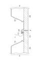
- FIG. 2 is a cross-sectional view of two mated deck plate assemblies taken along a short side thereof.
- FIG. 13 is a cross-sectional view of two mated deck plate assemblies according to another embodiment.
- the deck plate assembly 1 is a perspective view of a deck plate assembly 1 according to one embodiment of the present invention.
- the deck plate assembly 1 includes a deck plate 10 and a decorative material 20.
- the deck plate 10 is a corrugated steel plate formed by roll forming a thin steel plate that has been subjected to a surface treatment such as zinc plating.
- the deck plate 10 does not need to be subjected to a surface treatment such as plating.
- the deck plate 10 has a plurality of alternating peaks 11 and valleys 13 that extend in the longitudinal direction L, and has a structure in which adjacent peaks 11 and valleys 13 are connected by inclined portions 15, so that the peaks 11 and valleys 13 form a continuous wave shape in the short direction W.
- the peaks 11 are flat portions that are located above the upper surfaces of the support beams B1 and B2 when the deck plate assembly 1 is spanned between a support beam B1 and another adjacent support beam B2 (hereinafter also referred to as the "spanning state") as shown in FIG. 2, and are plate-shaped portions that extend in the longitudinal direction L.
- the valley portion 13 is parallel or approximately parallel to the peak portion 11 and is formed flat. In the spanning state, the valley portion 13 of the deck plate 10 arranged on the outermost side in the short direction W, which is in contact with the support beams B1 and B2, is placed on each of the support beams B1 and B2.
- the inclined portion 15 is a portion that connects the peak portion 11 and the valley portion 13, and is a plate-like portion that extends in the longitudinal direction L.
- the inclined portion 15 extends obliquely from the side edge of the peak portion 11 toward the side edge of the valley portion 13 in the short direction W.
- the deck plate 10 has, for example, two peaks 11, one valley 13, and two pairs of inclined portions 15 in one unit width X in the short side direction W, and is formed in a wave shape in a cross section along the short side direction W.
- one or three or more peaks 11 may be provided on the deck plate 10 of one unit width X.
- at least a part of the valley portion 13 is provided on both ends in the short side direction W of the deck plate 10, and when the deck plate assembly 1 is connected to another deck plate assembly 1 in the short side direction W, the connection portion between the deck plate assemblies 1 functions as the valley portion 13.
- the deck plate assembly 1 may be end-closed (hereinafter also referred to as "enclo processing") at both ends in the longitudinal direction L.
- a decorative material 20 is provided on the underside of the deck plate 10.
- the decorative material 20 is fastened to the deck plate 10 at a pitch of 300 to 600 mm in the short direction and at a pitch of 300 to 1500 mm in the long direction, so that the deck plate 10 and the decorative material 20 are stably fixed.
- the decorative material 20 is, for example, a wooden board formed into a board shape, and is fixed to the underside of the valley portion 13 using screws or the like.
- the decorative material 20 When the decorative material 20 is a wooden board, it may be not only sawn lumber, but also wood materials, for example, laminated lumber with improved strength, fire resistance, flame retardant performance, or both, by chemical treatment or addition of resin, so-called engineered wood such as LVL, or may be wood with improved resistance to mold and decay fungi.
- engineered wood such as LVL
- the decorative material 20 is made of wood, it is possible to simultaneously realize environmental considerations such as a CO 2 stock effect and improvement of the living environment such as moisture absorption and sound absorption.
- the decorative material 20 is attached to the deck plate 10 by any method other than screws, as long as it is attached by adhesive or other means, and the attachment method is not limited.
- the decorative material 20 is not limited to being attached so as to be in direct contact with the underside of the valley portion 13 of the deck plate 10, but may be attached at a distance from the underside of the valley portion 13 of the deck plate 10 via a member such as a pipe material or a steel material.
- the deck plate assembly 1 only needs to have the decorative material 20 attached directly or indirectly to the underside of the deck plate 10 by some means.
- the decorative material 20 may be a design finishing material that covers the underside of the deck plate assembly 1 exposed to the floor directly below between the support beams B1, B2 when the deck plate assembly 1 is placed on the support beams B, thereby improving the appearance.
- the deck plate 10 further has a first fitting portion 21 formed by bending the end of the valley portion 13 to form a curved up hook shape, and a second fitting portion 22 formed in a hook shape that is curved upside down from the first fitting portion 21.
- the first fitting portion 21 is provided at one end of the deck plate 10 in the short direction W so as to retract into the end of the decorative material 20 provided on the underside of the deck plate 10, and the second fitting portion 22 is provided at the other end of the deck plate 10 in the short direction W so as to protrude from the end of the decorative material 20 provided on the underside of the deck plate 10. Therefore, the end of the decorative material 20 provided on the first fitting portion 21 side extends further in the short direction than the first fitting portion 21.
- the first fitting portion 21 and the second fitting portion 22 are formed so that when two deck plate assemblies 1 are fitted together as described below, the undersides of the respective decorative materials 20 are approximately flush with each other.
- the first fitting portion 21 is provided at one end of the deck plate 10 in the short side direction W so as to protrude relative to the end of the decorative material 20 provided on the underside of the deck plate 10
- the second fitting portion 22 may be provided at the other end of the deck plate 10 in the short side direction W so as to retract relative to the end of the decorative material 20 provided on the underside of the deck plate 10, or the end of the deck plate 10 and the end of the decorative material 20 may be on the same plane in the height direction.
- a decorative material 20 having a unit width equal to the unit width X of the deck plate 10 is pre-assembled at a factory or the like on the underside of the deck plate 10.
- the decorative material 20 also serves as an adjustment guide for the play that is in principle generated between the first fitting portion 21 and the second fitting portion in the short side direction W, so that the effort of planning careful construction of the deck plate assembly 1 to ensure the unit width as designed is eliminated. This allows efficient and precise work during upward work in ceiling finishing construction.
- the decorative material 20 can be placed with appropriate dimensions between the support beams B1 and B2 in the short side direction W on which the deck plate 10 rests.
- a joint such as a joint for fitting two contacting decorative materials 20 together can be provided on the side of the end of the decorative material 20 in the short direction W.
- any equipment such as air conditioning equipment, fire extinguishing equipment, or wiring equipment may be provided in the space formed between the peaks 11 and the decorative material 20 of the deck plate 10.
- any equipment such as air conditioning equipment, fire extinguishing equipment, or wiring equipment may be provided in the space formed between the peaks 11 and the decorative material 20 of the deck plate 10.
- the deck plate 10 is not limited to a deck plate formed of peaks 11 and valleys 13 as described above, but may be a flat deck plate with ribs formed on a flat plate, or a reinforced deck plate with reinforced bar trusses attached.
- FIGs 3(a) to (d) are diagrams showing a construction method for laying two deck plate assemblies 1A and 1B according to this embodiment.
- the width of the decorative material 20 may be shortened by 50 mm in order to place, for example, 50 mm of the deck plate on the support beam B1.
- the end 23B of the decorative material 20B on the second fitting portion 22B side of the second deck plate assembly 1B is placed on the end 23A of the decorative material 20A on the first fitting portion 21A side of the first deck plate assembly 1A.
- the end 23B of the decorative material 20B of the second deck plate assembly 1B is tilted around the lower corner 25B of the end 23B until the side of the end 23B comes into contact with the first fitting portion 21A of the first deck plate 10A.
- the angle of inclination may be set appropriately depending on the shape and position of the fitting portions 21A, 22B, the thickness of the decorative materials 20A, 20B, etc.
- the end 23B of the second deck plate assembly 1B comes off the end 23A of the first deck plate assembly 1A.
- This causes the first mating portion 21A of the first deck plate 10A to come into contact with the second mating portion 22B of the second deck plate 10B.
- the second deck plate assembly 1B is pivoted downward relative to the first deck plate assembly 1A, so that the first mating portion 21A and the second mating portion 22B are mated.
- the first deck plate assembly 1A and the second deck plate assembly 1B can be laid so that the undersides of the decorative materials 20A, 20B are flush with each other.
- flashing 20'' is installed separately in areas where the unit width of the deck plate assembly does not match the width of the ceiling (see Figure 2).
- the fitting portion can be used as the installation reference, so that the deck plate installation work can be made more accurate and efficient than in the case of a single deck, the deck plate assembly can be easily laid, and the ceiling finishing work involving upward work can be omitted.
- the play between the adjacent decorative materials can be eliminated after the deck plate assembly is installed, which eliminates the need for error adjustment in construction and improves the finished appearance.
- the second deck plate assembly 1B when combining the second deck plate assembly 1B with the first deck plate assembly 1A, the second deck plate assembly 1B can be placed on the decorative material 20A of the first deck plate assembly 1A to bear part of its weight, which reduces the workload and prevents the second deck plate assembly 1B from falling off unintentionally. Therefore, the work can be performed safely.
Landscapes
- Engineering & Computer Science (AREA)
- Architecture (AREA)
- Physics & Mathematics (AREA)
- Electromagnetism (AREA)
- Civil Engineering (AREA)
- Structural Engineering (AREA)
- Floor Finish (AREA)
Priority Applications (1)
| Application Number | Priority Date | Filing Date | Title |
|---|---|---|---|
| JP2025523971A JP7841677B2 (ja) | 2024-01-05 | 2024-12-26 | デッキプレートアセンブリの設置方法 |
Applications Claiming Priority (2)
| Application Number | Priority Date | Filing Date | Title |
|---|---|---|---|
| JP2024-000851 | 2024-01-05 | ||
| JP2024000851 | 2024-01-05 |
Publications (1)
| Publication Number | Publication Date |
|---|---|
| WO2025146802A1 true WO2025146802A1 (ja) | 2025-07-10 |
Family
ID=96300389
Family Applications (1)
| Application Number | Title | Priority Date | Filing Date |
|---|---|---|---|
| PCT/JP2024/046117 Pending WO2025146802A1 (ja) | 2024-01-05 | 2024-12-26 | デッキプレートアセンブリおよびその設置方法 |
Country Status (2)
| Country | Link |
|---|---|
| JP (1) | JP7841677B2 (https=) |
| WO (1) | WO2025146802A1 (https=) |
Citations (7)
| Publication number | Priority date | Publication date | Assignee | Title |
|---|---|---|---|---|
| JPS53146222U (https=) * | 1977-04-25 | 1978-11-17 | ||
| WO2017061533A1 (ja) * | 2015-10-09 | 2017-04-13 | ケンテック株式会社 | 天井鉄筋構造材および外壁鉄筋構造材並びに建造物 |
| JP2019123996A (ja) * | 2018-01-12 | 2019-07-25 | ケンテック株式会社 | デッキプレート |
| WO2022004452A1 (ja) * | 2020-06-29 | 2022-01-06 | ケンテック株式会社 | フラットデッキ |
| WO2022004453A1 (ja) * | 2020-06-30 | 2022-01-06 | ケンテック株式会社 | 鉄筋付きデッキプレート |
| WO2022004451A1 (ja) * | 2020-06-29 | 2022-01-06 | ケンテック株式会社 | 溝形デッキプレート |
| CN216142256U (zh) * | 2021-06-17 | 2022-03-29 | 南通欧本建筑科技有限公司 | 一种带抗剪件和防火装饰层的钢承板 |
Family Cites Families (2)
| Publication number | Priority date | Publication date | Assignee | Title |
|---|---|---|---|---|
| JP5724061B2 (ja) | 2010-10-25 | 2015-05-27 | コクヨ株式会社 | 組立式収納家具 |
| JP2021123921A (ja) | 2020-02-04 | 2021-08-30 | 日本製鉄株式会社 | 鋼矢板の継手構造及び鋼矢板構造体 |
-
2024
- 2024-12-26 WO PCT/JP2024/046117 patent/WO2025146802A1/ja active Pending
- 2024-12-26 JP JP2025523971A patent/JP7841677B2/ja active Active
Patent Citations (7)
| Publication number | Priority date | Publication date | Assignee | Title |
|---|---|---|---|---|
| JPS53146222U (https=) * | 1977-04-25 | 1978-11-17 | ||
| WO2017061533A1 (ja) * | 2015-10-09 | 2017-04-13 | ケンテック株式会社 | 天井鉄筋構造材および外壁鉄筋構造材並びに建造物 |
| JP2019123996A (ja) * | 2018-01-12 | 2019-07-25 | ケンテック株式会社 | デッキプレート |
| WO2022004452A1 (ja) * | 2020-06-29 | 2022-01-06 | ケンテック株式会社 | フラットデッキ |
| WO2022004451A1 (ja) * | 2020-06-29 | 2022-01-06 | ケンテック株式会社 | 溝形デッキプレート |
| WO2022004453A1 (ja) * | 2020-06-30 | 2022-01-06 | ケンテック株式会社 | 鉄筋付きデッキプレート |
| CN216142256U (zh) * | 2021-06-17 | 2022-03-29 | 南通欧本建筑科技有限公司 | 一种带抗剪件和防火装饰层的钢承板 |
Also Published As
| Publication number | Publication date |
|---|---|
| JP7841677B2 (ja) | 2026-04-07 |
| JPWO2025146802A1 (https=) | 2025-07-10 |
Similar Documents
| Publication | Publication Date | Title |
|---|---|---|
| JP7756093B2 (ja) | 構造パネルおよび金属支持体を含む複合構造体 | |
| US6363674B1 (en) | Premanufactured structural building panels | |
| US5930965A (en) | Insulated deck structure | |
| JP6841439B2 (ja) | 建築工法および建築構造 | |
| US20080053031A1 (en) | Assembling and Arrangement Flat Element Consisting of One or Several Elements | |
| JP4500981B2 (ja) | 床構造の構築方法及び床構造 | |
| WO2025146802A1 (ja) | デッキプレートアセンブリおよびその設置方法 | |
| JP2023162735A (ja) | 合成スラブの施工方法及び合成スラブ | |
| JP7288787B2 (ja) | 木造建物の床パネル | |
| JP6919480B2 (ja) | 治工具及び積層梁構造体と、積層梁構造体の施工方法 | |
| WO2013015316A1 (ja) | 組積造建物および組積造建物の構築方法 | |
| KR100665359B1 (ko) | 종이 골판지를 포함한 거푸집패널 | |
| JP7744545B1 (ja) | デッキプレートと天井仕上げ木質板とを梁に設置する方法 | |
| EP2261434B1 (en) | Roof rafter | |
| JP7601311B2 (ja) | 鉄骨造の天井下地の構築方法 | |
| AU2010101526A6 (en) | Floor structure for wooden building | |
| RU107204U1 (ru) | Перекрытие для деревянного здания (варианты) | |
| JP7470243B1 (ja) | 複合梁および複合梁の施工方法 | |
| CN223805701U (zh) | 一种墙板与屋板的连接件 | |
| JP7457548B2 (ja) | 木造建物の床組構造 | |
| JP7763810B2 (ja) | 乾式屋根及びデッキプレート | |
| JP7577016B2 (ja) | 構造部材の接続部構造 | |
| EP1811097A2 (en) | Building element | |
| JP7852192B2 (ja) | 合成スラブ構造、及び合成スラブ構造の施工方法 | |
| JPS60215957A (ja) | プレハブ構造用壁板及び該壁板を含むプレハブ構造 |
Legal Events
| Date | Code | Title | Description |
|---|---|---|---|
| ENP | Entry into the national phase |
Ref document number: 2025523971 Country of ref document: JP Kind code of ref document: A |
|
| WWE | Wipo information: entry into national phase |
Ref document number: 2025523971 Country of ref document: JP |
|
| 121 | Ep: the epo has been informed by wipo that ep was designated in this application |
Ref document number: 24915491 Country of ref document: EP Kind code of ref document: A1 |